KR20130094402A - Desk top-type universal dock - Google Patents
Desk top-type universal dockDownload PDFInfo
- Publication number
- KR20130094402A KR20130094402AKR1020120015608AKR20120015608AKR20130094402AKR 20130094402 AKR20130094402 AKR 20130094402AKR 1020120015608 AKR1020120015608 AKR 1020120015608AKR 20120015608 AKR20120015608 AKR 20120015608AKR 20130094402 AKR20130094402 AKR 20130094402A
- Authority
- KR
- South Korea
- Prior art keywords
- connector
- universal
- dock
- pedestal
- housing
- Prior art date
- Legal status (The legal status is an assumption and is not a legal conclusion. Google has not performed a legal analysis and makes no representation as to the accuracy of the status listed.)
- Ceased
Links
Images


Classifications
- G—PHYSICS
- G06—COMPUTING OR CALCULATING; COUNTING
- G06F—ELECTRIC DIGITAL DATA PROCESSING
- G06F1/00—Details not covered by groups G06F3/00 - G06F13/00 and G06F21/00
- G06F1/16—Constructional details or arrangements
- G—PHYSICS
- G06—COMPUTING OR CALCULATING; COUNTING
- G06F—ELECTRIC DIGITAL DATA PROCESSING
- G06F1/00—Details not covered by groups G06F3/00 - G06F13/00 and G06F21/00
- G06F1/16—Constructional details or arrangements
- G06F1/1613—Constructional details or arrangements for portable computers
- G06F1/1632—External expansion units, e.g. docking stations
- G—PHYSICS
- G06—COMPUTING OR CALCULATING; COUNTING
- G06F—ELECTRIC DIGITAL DATA PROCESSING
- G06F1/00—Details not covered by groups G06F3/00 - G06F13/00 and G06F21/00
- G06F1/16—Constructional details or arrangements
- G06F1/1613—Constructional details or arrangements for portable computers
- G06F1/1633—Constructional details or arrangements of portable computers not specific to the type of enclosures covered by groups G06F1/1615 - G06F1/1626
- G06F1/1656—Details related to functional adaptations of the enclosure, e.g. to provide protection against EMI, shock, water, or to host detachable peripherals like a mouse or removable expansions units like PCMCIA cards, or to provide access to internal components for maintenance or to removable storage supports like CDs or DVDs, or to mechanically mount accessories
- G06F1/166—Details related to functional adaptations of the enclosure, e.g. to provide protection against EMI, shock, water, or to host detachable peripherals like a mouse or removable expansions units like PCMCIA cards, or to provide access to internal components for maintenance or to removable storage supports like CDs or DVDs, or to mechanically mount accessories related to integrated arrangements for adjusting the position of the main body with respect to the supporting surface, e.g. legs for adjusting the tilt angle
- H—ELECTRICITY
- H02—GENERATION; CONVERSION OR DISTRIBUTION OF ELECTRIC POWER
- H02J—CIRCUIT ARRANGEMENTS OR SYSTEMS FOR SUPPLYING OR DISTRIBUTING ELECTRIC POWER; SYSTEMS FOR STORING ELECTRIC ENERGY
- H02J7/00—Circuit arrangements for charging or depolarising batteries or for supplying loads from batteries
- H02J7/0042—Circuit arrangements for charging or depolarising batteries or for supplying loads from batteries characterised by the mechanical construction
- H02J7/0044—Circuit arrangements for charging or depolarising batteries or for supplying loads from batteries characterised by the mechanical construction specially adapted for holding portable devices containing batteries
- H—ELECTRICITY
- H04—ELECTRIC COMMUNICATION TECHNIQUE
- H04M—TELEPHONIC COMMUNICATION
- H04M1/00—Substation equipment, e.g. for use by subscribers
- H04M1/02—Constructional features of telephone sets
- H04M1/0202—Portable telephone sets, e.g. cordless phones, mobile phones or bar type handsets
- H04M1/0254—Portable telephone sets, e.g. cordless phones, mobile phones or bar type handsets comprising one or a plurality of mechanically detachable modules
- H—ELECTRICITY
- H04—ELECTRIC COMMUNICATION TECHNIQUE
- H04M—TELEPHONIC COMMUNICATION
- H04M1/00—Substation equipment, e.g. for use by subscribers
- H04M1/02—Constructional features of telephone sets
- H04M1/04—Supports for telephone transmitters or receivers
- H—ELECTRICITY
- H04—ELECTRIC COMMUNICATION TECHNIQUE
- H04M—TELEPHONIC COMMUNICATION
- H04M1/00—Substation equipment, e.g. for use by subscribers
- H04M1/02—Constructional features of telephone sets
- H04M1/04—Supports for telephone transmitters or receivers
- H04M1/06—Hooks; Cradles
Landscapes
- Engineering & Computer Science (AREA)
- Theoretical Computer Science (AREA)
- Computer Hardware Design (AREA)
- General Engineering & Computer Science (AREA)
- Human Computer Interaction (AREA)
- Physics & Mathematics (AREA)
- General Physics & Mathematics (AREA)
- Signal Processing (AREA)
- Power Engineering (AREA)
- Telephone Set Structure (AREA)
- Connector Housings Or Holding Contact Members (AREA)
Abstract
Translated fromKoreanDescription
Translated fromKorean본 발명은 휴대 단말기에 관한 것으로서, 특히 다양한 사이즈나 유형의 휴대 단말기를 충전하거나 거치할 수 있는 데스크 탑 유형의 유니버셜 도크에 관한 것이다.
BACKGROUND OF THE INVENTION 1. Field of the Invention The present invention relates to portable terminals, and more particularly, to a desktop type universal dock capable of charging or mounting various sizes or types of portable terminals.
일반적인 휴대 단말기는 셀룰러 폰(cellular phone), 피디에이(PDA), 스마트 폰(smart phone), 태블릿 피씨(tablet PC) 등을 지칭한다. 휴대 단말기는 전원이 전부 소모되는 경우, 충전 거치대를 이용하여 재충전하여 사용되고, 티브이 모드나 디엠비 모드에서 경사지게 거치가능하여, 표시부에 디스플레이된 화면 보기가 편리한 이점도 제공하였다.Common mobile terminals refer to cellular phones, PDAs, smart phones, tablet PCs, and the like. The portable terminal is recharged using a charging cradle when all of the power is consumed, and can be tilted in a TV mode or a DMB mode, thereby providing a convenient view of the screen displayed on the display unit.
상기 휴대 단말기는 배터리가 내장형 또는 착탈형으로 구성되는데, 전원이 소모되면, 재충전을 위하여 충전 거치대가 사용되어져 왔다. 상기 충전 거치대는 휴대 단말기가 수평 또는 수직 상태로 거치될 수 있으나, 경사지게 거치되는 방식이 일반적이다.The portable terminal has a built-in battery or a removable battery. When power is consumed, a charging cradle has been used for recharging. The charging cradle may be mounted in a horizontal or vertical state, but the charging cradle is generally inclined.
또한, 상기 충전 거치대는 다양한 유형으로 이루어지는데, 대체적으로 휴대 단말기가 거치되는 전용 수용 공간과, 휴대 단말기의 충전 단자나, 별도의 보조 배터리 팩 충전 단자와 접속을 위한 콘넥터(접속 콘넥터)가 구비되는 구성으로 이루어지는 것이 일반적이다.In addition, the charging cradle is made of various types, generally having a dedicated accommodating space in which the portable terminal is mounted, and a connector (connection connector) for connection with the charging terminal of the portable terminal or a separate auxiliary battery pack charging terminal. It is common to consist of a structure.
그러나, 종래의 휴대 단말기의 거치대는 각각의 휴대 단말기 사양에 맞는 전용 충전 거치대를 사용하게 되어서, 사용자의 입장에서 휴대 단말기가 고장나거나, 분실하여 교체하는 경우에 비경제적인 문제가 있다. 교체한 휴대 단말기에 전용하는 충전 거치대를 구입해야 하는 비 경제적인 요소가 있다.However, the cradle of the conventional portable terminal is to use a dedicated charging cradle that meets the specifications of each portable terminal, there is a problem that is uneconomical when the portable terminal is broken, lost or replaced from the user's point of view. There is an uneconomical factor in purchasing a charging cradle dedicated to the replaced mobile terminal.
특히, 각 제조사마다 다른 충전 거치대가 사용되거나, 각 모델마다 다른 충전 거치대가 사용되어져서, 제조사의 관점에서도 각 휴대 단말기에 전용하는 충전 거치대를 제작해야 함으로서, 휴대 단말기의 원가 상승이 한 요인이 된다.
In particular, different charging cradles are used for each manufacturer, or different charging cradles are used for each model, and thus, the cost of the mobile terminal becomes a factor because a manufacturer needs to manufacture a charging cradle dedicated to each mobile terminal. .
따라서, 본 발명은 휴대 단말기의 전체적인 크기(가로, 세로 및 두께 사이즈)나 유형(바 타입, 슬라이딩 타입, 폴더 타입 등등)에 제약받지 않고, 사용자의 입장에서 편리하게 거치할 수 있는 데스크 탑 유형의 유니버셜 도크를 제공함에 있다.Therefore, the present invention is not limited to the overall size (horizontal, vertical and thickness size) or type (bar type, sliding type, folder type, etc.) of the mobile terminal, and is a desktop type that can be conveniently mounted from the user's point of view. To provide a universal dock.
또한, 본 발명은 제조업자의 관점에서 생산 단가를 줄일 수 있는 경제적인 데스크 탑 유형의 유니버셜 도크를 제공함에 있다.
It is also an object of the present invention to provide an economical desktop type universal dock that can reduce production costs.
상기한 과제들을 해결하기 위하여, 본 발명은 휴대 단말기의 도크에 있어서, 탁상에 놓이는 받침대; 상기 받침대에 결합되어, 다양한 사이즈나 유형의 휴대 단말기 거치가 가능한 범용 거치대; 및 상기 범용 거치대에 회전가능하게 장착된 콘넥터를 포함한다.In order to solve the above problems, the present invention, in the dock of the portable terminal, a pedestal placed on the table; It is coupled to the pedestal, the universal cradle capable of mounting a mobile terminal of various sizes or types; And a connector rotatably mounted to the universal holder.
또한, 본 발명은 휴대 단말기의 도크에 있어서, 받침대; 상기 받침대에 경사지게 결합되고, 다양한 사이즈나 유형의 휴대 단말기 거치가 가능한 범용 거치대; 상기 거치대에 하우징에 의해 회전가능하게 장착된 콘넥터; 및 상기 받침대에 장착되며, 상기 하우징과 밀착된 상태를 유지하여 상기 콘넥터를 소정 상태로 복귀하도록 지지하는 탄성체로 구성된다.
In addition, the present invention provides a dock of a portable terminal, comprising: a pedestal; A universal cradle coupled obliquely to the pedestal and capable of mounting various sizes or types of portable terminals; A connector rotatably mounted to the holder by a housing; And an elastic body mounted on the pedestal and supporting the connector to return to a predetermined state while maintaining a state in close contact with the housing.
이상으로 살펴본 바와 같이, 본 발명은 다양한 사이즈나 유형의 휴대 단말기 거치가 가능해져서 사용자나 제조업자의 관점에서 경제적이다.
As described above, the present invention enables the mounting of portable terminals of various sizes and types, and is economical from the viewpoint of a user or a manufacturer.
도 1은 본 발명에 따른 유니버셜 도크를 나타내는 조립 사시도.
도 2는 본 발명에 따른 유니버셜 도크의 콘넥터의 회전 전 상태를 나타내는 측면도.
도 3은 본 발명에 따른 유니버셜 도크의 콘넥터의 회전 후 상태를 나타내는 측면도.
도 4는 본 발명에 따른 유니버셜 도크를 나타내는 분리 사시도.
도 5는 본 발명에 따른 유니버셜 도크의 콘넥터 장착 전 상태를 나타내는 사시도.
도 6은 본 발명에 따른 유니버셜 도크의 콘넥터 장착 후 상태를 나타내는 사시도.
도 7은 본 발명에 다른 유니버셜 도크의 콘넥터 회전 전 상태를 나타내는 단면도.
도 8은 본 발명에 따른 유니버셜 도크의 콘넥터 회전 후 상태를 나타내는 단면도.
도 9는 본 발명에 따른 유니버셜 도크의 콘넥터에 휴대 단말기가 접속되기 전 상태를 나타내는 측면도.
도 10은 본 발명에 따른 유니버셜 도크의 콘넥터에 휴대 단말기가 접속된 후 회전하여 거치대에 경사지게 거치된 상태를 나타내는 측면도.1 is an assembled perspective view showing a universal dock according to the present invention.
Figure 2 is a side view showing a state before rotation of the connector of the universal dock according to the present invention.
Figure 3 is a side view showing a state after the rotation of the connector of the universal dock according to the invention.
4 is an exploded perspective view showing a universal dock according to the present invention.
Figure 5 is a perspective view showing a state before mounting the connector of the universal dock according to the invention.
Figure 6 is a perspective view showing a state after mounting the connector of the universal dock according to the present invention.
Figure 7 is a cross-sectional view showing a state before the rotation of the connector of the universal dock according to the present invention.
8 is a cross-sectional view showing a state after the rotation of the connector of the universal dock according to the present invention.
9 is a side view showing a state before the portable terminal is connected to the connector of the universal dock according to the present invention.
10 is a side view showing a state in which the portable terminal is connected to the connector of the universal dock and then inclinedly mounted on the cradle according to the present invention.
이하에서는 첨부된 도면을 참조하여 본 발명을 설명하기로 한다. 동일한 참조부호는 동일한 구성요소를 지칭한다.Hereinafter, with reference to the accompanying drawings will be described the present invention. Like reference numerals refer to like elements.
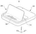
본 발명을 설명함에 있어서, 도 1에 'X축', 'Y축' 및 'Z축'이 도시되었는데, 'X축'은 도크의 좌우(가로) 방향을 의미하고, 'Y축'은 도크의 전후(세로) 방향을 의미하며, 'Z축'은 도크의 상하 방향을 지칭한다.In describing the present invention, 'X-axis', 'Y-axis' and 'Z-axis' are illustrated in FIG. 1, where 'X-axis' refers to the left and right directions of the dock, and 'Y-axis' refers to the dock. Refers to the front and rear (vertical) direction of, 'Z axis' refers to the up and down direction of the dock.
도 1에 도시된 바와 같이, 본 발명에 따른 유니버셜 도크(10)는 휴대 단말기의 거치대 또는 충전 거치대로서, 특히 다양한 사이즈나 유형의 휴대 단말기의 거치대 또는 충전 거치대로 사용된다. 상기 언급된 다양한 사이즈의 휴대 단말기는 가로 길이, 세로 길이 및 두께가 각각 다양한 휴대 단말기 사이즈를 의미한다. 즉, 본 발명에 따른 유니버셜 도크(10)는 휴대 단말기 거치의 관점에서, 휴대 단말기 크기로부터 자유롭다는 것을 의미하는 것으로, 휴대 단말기의 가로 길이/세로 길이/두께와 상관없이 일정 각도로 거치가능하다.As shown in FIG. 1, the
또한, 상기 다양한 유형의 휴대 단말기는 외관상으로 구분되는 바 타입이나, 슬라이딩 타입 또는 폴더 타입 등을 포함할 수 있고, 셀룰러 폰, 피디에이, 스마트 폰, 태블릿 피씨, 전자북, 엠피쓰리 등을 포함할 수 있다.In addition, the various types of portable terminals may include a bar type, a sliding type, a folder type, and the like, which are distinguished in appearance, and may include a cellular phone, a PD, a smartphone, a tablet PC, an electronic book, an MP3, and the like. have.
도 1 내지 도 3에 도시된 바와 같이, 상기 유니버셜 도크(10)는 받침대(100)와, 범용 거치대(200) 및 콘넥터(300)를 포함한다. 상기 받침대(100)는 탁상에 높이는 부분으로서, 상기 거치대(200)가 경사지게 결합된다. 상기 콘넥터(300)는 상기 거치대(200)에 장착되어 항시 노출된다. 도 2에는 상기 콘넥터(300)가 외력을 받지 않아서 직립된 상태를 나타내고, 도 3에는 상기 콘넥터(300)가 외력을 받아서 소정 각도로 시계 방향으로 회전된 상태를 나타낸다. 도 1의 참조부호 110은 개구를 지칭한다.As shown in FIGS. 1 to 3, the
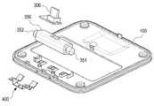
도 4에 도시된 바와 같이, 상기 받침대(100)는 전방 영역에 하우징(350)을 회전가능게 구성하기 위한 한 쌍의 힌지 아암(120,122)을 구비한다. 상기 힌지 아암(120,122)은 가로 방향으로 연장된다. 상기 거치대(200)는 상기 받침대(100)에 장착되어 다양한 사이즈나 유형의 휴대 단말기를 일정 각도로 지지한다. 특히, 상기 거치대(200)는 휴대 단말기가 거치된 경우, 휴대 단말기의 중간 이하의 영역, 즉 하부와 접촉되어 지지된다. 휴대 단말기가 상기 거치대(200)에 경사지게 거치된 상태가 도 10에 도시되었다.As shown in FIG. 4, the
상기 거치대(200)는 베이스(210)와, 상기 베이스(210)에서 일체형으로 소정 방향으로 연장된 지지대(220)를 포함한다. 상기 베이스(210)는 상기 콘넥터(300)가 회전가능하게 수용되어 배치되고, 상기 받침대(100)에 고정된다. 상기 베이스(210)는 상기 받침대(100)에 경사지게 고정된다. 또한, 상기 받침대(210)는 상기 콘넥터(300)가 고정된 하우징(350)을 수용하는 개구(212)를 구비하고, 하단에 다수개의 체결구(214), 예를 들어 후크가 구비되어서, 상기 받침대(100)에 고정된다.The
상기 지지대(220)는 상기 베이스(210)에서 대략 수직으로 연장되어서, 상기 베이스(210)가 받침대에 경사지게 장착됨에 따라서 상기 받침대(100)에서 경사방향으로 소정의 길이로 연장된다. 상기 지지대(220)는 판 형상이며, 상기 콘넥터(300)에 접속된 휴대 단말기를 경사지게 유지시킨다. 즉, 상기 거치된 휴대 단말기의 저면과 접촉하여 지지한다.The
상기 콘넥터(300)는 범용 콘넥터로서, 상기 받침대(210)에 수용되어 회전가능하게 장착된다. 도 2는 상기 콘넥터(300)가 회전 전 상태이고, 도 3은 상기 콘넥터(300)가 회전후 상태를 나타낸다.The
상기 하우징(350)은 상기 콘넥터(300)가 수용되어 상기 베이스에서 회전시키기 위한 부품으로서, 양 측면에 힌지(351,352)가 각각 구비된다. 아울러, 상기 하우징(350)은 탄성체(400)에 의해 지지되어 초기 위치(도 2에 도시됨)로 복귀하는 힘을 제공받는다.The
상기 탄성체(400)는 상기 베이스(100)에 내부에 장착되며, 상기 하우징(350) 소정 부분과 밀착된 상태를 유지하게 배치되어 짐으로서, 상기 하우징(350)을 항시 원위치로 이동하는 힘을 제공한다. 상기 탄성체(400)는 하나의 판 스프링 형상으로, 다수개의 고정단(410,411,412)과, 적어도 하나 이상의 자유단(413,414)으로 구성된다. 상기 고정단(410,411,412)은 상기 베이스(100)에 체결되어 고정되는 부분이고, 상기 자유단(413,414)은 상기 하우징(350) 외면과 밀착되게 배치되는 부분이다. 상기 하우징(350)의 회전동작에 따라서, 상기 자유단(413,414)은 상기 하우징 외면과 슬랑이딩을 수행한다. 상기 고정단은 3개가 구비되는데, 중앙 고정단(410)과, 좌우 고정단(411,412)을 포함한다. 아울러, 상기 자유단은 좌우 고정단(411,412)에서 각각 수직 방향으로 연장된 좌우 자유단(413,414)을 포함한다. 상기 좌우 자유단(413,414)은 서로 대칭으로 구성되어, 상기 하우징(350) 외면에 각각 대칭으로 밀착된다. 상기 좌우 자유단(413,414)은 각각 곡형으로 구성되어서, 상기 하우징(350) 외면과 슬라이딩이 원할하다. 상기 중앙 고정단(410)에서 좌우로 각각 2번 벤딩하여 좌우 고정단(411,412)이 구성되고, 상기 좌우 고정단(411,412)에서 다수번 벤딩되어 좌우 자유단(413,414)이 구성된다.The
도 5, 도 6에 도시된 바와 같이, 상기 하우징에 콘넥터가 고정된 후, 상기 하우징의 힌지가 베이스에 구비된 지지대에 배치되는데, 상기 하우징과 베이스 사이에 탄성체가 장착된다. 상기 탄성체의 고정단은 미도시된 체결구에 의해 고정된다.5 and 6, after the connector is fixed to the housing, the hinge of the housing is disposed on a support provided in the base, an elastic body is mounted between the housing and the base. The fixed end of the elastic body is fixed by a fastener not shown.
도 7, 도 8을 참조하여 상기 콘넥터(300)가 장착된 하우징(350)의 회전 동작에 대해서 설명하기로 한다. 도 7에 도시된 바와 같이, 상기 탄성체(400)는 베이스(100)에 장착되면, 상기 좌우 자유단(413,414)은 상기 하우징(350) 외면 중, 저면에 밀착된 상태를 유지하면서, 상기 하우징(350) 직립 상태를 지지한다. 상기 하우징(350)에 외력, 구체적으로 휴대 단말기가 상기 콘넥터(300)에 접속된 후 휴대 단말기 자중에 의해 회전하면, 상기 좌우 자유단(413,414)은 대략 하방으로 이동하면서 상기 하우징(350) 저면 소정 영역과 밀착된 상태를 유지하여, 상기 회전된 하우징(350)을 지지한다. 상기 콘넥터(300)에 접속된 휴대 단말기를 제거하면, 상기 탄성체(400)에 의해 상기 하우징(350)은 도 7과 같은 초기 위치로 복귀한다. 상기 하우징(350)의 복귀력은 상기 탄성체(400)가 제공한다. 상기 콘넥터(300)의 회전 동작 시, 상기 하우징(350) 외면 소정부분과 상기 좌우 자유단(413,414)은 슬라이딩 면접촉을 한다.7, the rotation operation of the
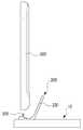
도 9, 도 10을 참조하여 상기 유니버셜 도크에 휴대 단말기(500)가 거치되는 과정을 설명하기로 한다. 휴대 단말기(500)는 상기 콘넥터(300)에 접속되면, 휴대 단말기(500) 자중에 의해 상기 콘넥터(300)는 회전하고, 상기 접속된 휴대 단말기(500)는 거치대(200)에 지지되는 상태를 유지한다. 이미 설명하였듯이, 상기 휴대 단말기(500)를 콘넥터(300)에서 분리하면, 상기 콘넥터(300)는 탄성체에 의해 다시 직립된 상태가 된다.A process in which the
Claims (13)
Translated fromKorean탁상에 놓이는 받침대;
상기 받침대에 결합되어, 다양한 사이즈나 유형의 휴대 단말기 거치가 가능한 범용 거치대; 및
상기 범용 거치대에 회전가능하게 장착된 콘넥터를 포함함을 특징으로 하는 유니버셜 도크.
In the dock of a mobile terminal,
Pedestals placed on the table;
It is coupled to the pedestal, the universal cradle capable of mounting a mobile terminal of various sizes or types; And
Universal dock, characterized in that it comprises a connector rotatably mounted to the universal cradle.
The universal dock as claimed in claim 1, wherein the holder supports a lower portion of the portable terminal.
상기 콘넥터가 회전가능하게 수용되어 배치되고, 상기 받침대에 경사지게 결합된 베이스; 및
상기 베이스에서 대략 수직방향으로 연장되어 상기 받침대에서 경사지게 위치하고, 상기 콘넥터에 접속된 휴대 단말기를 경사지게 유지시키는 지지대를 포함함을 특징으로 하는 유니버셜 도크.The method of claim 2, wherein the cradle
A base rotatably received and disposed at the connector, the base being inclinedly coupled to the pedestal; And
And a support extending from the base in a substantially vertical direction to be inclined at the pedestal and holding the portable terminal connected to the connector at an inclination.
The universal dock as set forth in claim 3, wherein the portable terminal is mounted inclined to the support by rotating to its own weight while being connected to the connector.
The universal dock as set forth in claim 1, wherein the portable terminal can be mounted on the holder regardless of the width / length / thickness.
4. The universal dock of claim 3 wherein the connector is rotatably mounted to the pedestal by a housing.
The universal dock as set forth in claim 6, wherein the base further includes an elastic body which is always in close contact with the predetermined portion of the housing, and the elastic body provides a force for always erecting the connector.
상기 베이스 내에 고정되는 적어도 하나 이상의 고정단; 및
상기 고정단에서 연장되어 상기 하우징 소정 부분과 밀착 배치되며, 상기 하우징 소정부분의 회전에 따라서 슬라이딩 면접촉하는 적어도 하나 이상의 곡형 자유단을 포함함을 특징으로 하는 유니버셜 도크.
The method of claim 7, wherein the elastic body is a leaf spring shape,
At least one fixed end fixed in the base; And
And at least one curved free end extending from the fixed end to be in close contact with the predetermined portion of the housing, the at least one curved free end sliding in surface contact with the rotation of the predetermined portion of the housing.
상기 베이스에 고정되는 중앙 고정단; 및
상기 중앙 고정단에서 벤딩되어 형성되며, 상기 중앙 고정단 양측으로 대칭으로 각각 위치하는 좌우 고정단을 포함하고,
상기 자유단은
상기 좌우 고정단에 각각 연장되며, 상기 좌우 고정단에서 다수 번 벤딩되어 각각 형성되는 좌우 자유단을 포함함을 특징으로 하는 유니버셜 도크.
The method of claim 8, wherein the fixed end
A central fixed end fixed to the base; And
It is formed to be bent at the central fixed end, and includes a left and right fixed end symmetrically positioned on both sides of the central fixed end,
The free end is
Universal docks, characterized in that extending to the left and right fixed ends, each of the left and right free ends formed by bending a plurality of times at the left and right fixed ends.
10. The universal dock of claim 9, wherein the left and right free ends move upward and downward within the base according to the rotation of the mounted portable terminal.
받침대;
상기 받침대에 경사지게 결합되고, 다양한 사이즈나 유형의 휴대 단말기 거치가 가능한 범용 거치대;
상기 거치대에 하우징에 의해 회전가능하게 장착된 콘넥터; 및
상기 받침대에 장착되며, 상기 하우징과 밀착된 상태를 유지하여 상기 콘넥터를 소정 상태로 복귀하도록 지지하는 탄성체로 구성되어짐을 특징으로 하는 포함함을 특징으로 하는 유니버셜 도크.
In the dock of a mobile terminal,
Pedestal;
A universal cradle coupled obliquely to the pedestal and capable of mounting various sizes or types of portable terminals;
A connector rotatably mounted to the holder by a housing; And
And a resilient body mounted on the pedestal, the elastic body supporting the connector to return to the predetermined state by maintaining the state in close contact with the housing.
The universal dock as set forth in claim 11, wherein the predetermined state of the connector is an upright state.
Priority Applications (4)
| Application Number | Priority Date | Filing Date | Title |
|---|---|---|---|
| KR1020120015608AKR20130094402A (en) | 2012-02-16 | 2012-02-16 | Desk top-type universal dock |
| US13/753,898US9118749B2 (en) | 2012-02-16 | 2013-01-30 | Desktop-type universal dock |
| EP13155474.3AEP2629172B1 (en) | 2012-02-16 | 2013-02-15 | Desktop-type universal dock |
| CN201310051351.0ACN103259893B (en) | 2012-02-16 | 2013-02-16 | Desktop-type universal dock |
Applications Claiming Priority (1)
| Application Number | Priority Date | Filing Date | Title |
|---|---|---|---|
| KR1020120015608AKR20130094402A (en) | 2012-02-16 | 2012-02-16 | Desk top-type universal dock |
Related Child Applications (1)
| Application Number | Title | Priority Date | Filing Date |
|---|---|---|---|
| KR1020180097272ADivisionKR101908013B1 (en) | 2018-08-21 | 2018-08-21 | Desk top-type universal dock |
Publications (1)
| Publication Number | Publication Date |
|---|---|
| KR20130094402Atrue KR20130094402A (en) | 2013-08-26 |
Family
ID=47900517
Family Applications (1)
| Application Number | Title | Priority Date | Filing Date |
|---|---|---|---|
| KR1020120015608ACeasedKR20130094402A (en) | 2012-02-16 | 2012-02-16 | Desk top-type universal dock |
Country Status (4)
| Country | Link |
|---|---|
| US (1) | US9118749B2 (en) |
| EP (1) | EP2629172B1 (en) |
| KR (1) | KR20130094402A (en) |
| CN (1) | CN103259893B (en) |
Families Citing this family (46)
| Publication number | Priority date | Publication date | Assignee | Title |
|---|---|---|---|---|
| US9274556B2 (en) | 2011-01-05 | 2016-03-01 | Mophie, Inc. | Tablet computer stand |
| JP5637567B2 (en)* | 2012-09-26 | 2014-12-10 | Necプラットフォームズ株式会社 | Cradle device |
| TWM460316U (en)* | 2013-04-24 | 2013-08-21 | Quanta Comp Inc | Supporting structure and electronic device using the same |
| US9545549B2 (en) | 2013-05-15 | 2017-01-17 | Cobra Golf Incorporated | Golf bag with a docking station for an electronic device |
| USD741334S1 (en)* | 2013-08-01 | 2015-10-20 | Unify Gmbh & Co. Kg | Docking station for telephone and flat computer |
| WO2015054242A1 (en)* | 2013-10-09 | 2015-04-16 | Mophie, Inc. | Dock station with movable support |
| USD712369S1 (en)* | 2013-12-16 | 2014-09-02 | Panasonic Corporation | Telephone base unit |
| USD722062S1 (en)* | 2014-07-02 | 2015-02-03 | Evernote Corporation | Tablet dish |
| TWI562478B (en)* | 2014-09-24 | 2016-12-11 | Hon Hai Prec Ind Co Ltd | Connector device |
| US10437288B2 (en) | 2014-10-06 | 2019-10-08 | Fasetto, Inc. | Portable storage device with modular power and housing system |
| CN204190438U (en)* | 2014-10-22 | 2015-03-04 | 深圳沃鹏无线科技有限公司 | A kind of stent-type wireless charger |
| USD806022S1 (en)* | 2015-01-06 | 2017-12-26 | John Paul Waring | Charging station |
| CN204350081U (en)* | 2015-01-22 | 2015-05-20 | 京东方光科技有限公司 | Portable type electronic product |
| US9338903B1 (en) | 2015-01-27 | 2016-05-10 | John Loscalzo | Mobile device cradle |
| KR20160105669A (en) | 2015-02-27 | 2016-09-07 | 삼성전자주식회사 | Connecter Module and Locking Device including the same |
| USD788699S1 (en)* | 2015-09-07 | 2017-06-06 | Gibson Innovations Belgium Nv | Charging stand |
| CN105226756A (en)* | 2015-10-27 | 2016-01-06 | 苏州凯丰电子电器有限公司 | A kind of handset charging holder easy to use |
| JP1561255S (en)* | 2015-12-18 | 2016-10-24 | ||
| CN107404555A (en)* | 2016-05-21 | 2017-11-28 | 麦广树 | Handset mounting with width adaptive mechanism |
| USD841576S1 (en)* | 2016-09-02 | 2019-02-26 | Design Pool Limited | Charging dock |
| CN210838302U (en)* | 2016-10-07 | 2020-06-23 | 菲力尔系统公司 | electronic module |
| CN107919549B (en)* | 2016-10-10 | 2020-05-19 | 神讯电脑(昆山)有限公司 | Transmission base of electronic device |
| US9742455B1 (en)* | 2016-10-18 | 2017-08-22 | Getac Technology Corporation | Transmission dock of electronic device |
| US11708051B2 (en) | 2017-02-03 | 2023-07-25 | Fasetto, Inc. | Systems and methods for data storage in keyed devices |
| USD847739S1 (en)* | 2017-04-28 | 2019-05-07 | Spigen Korea Co., Ltd. | Charging stand for electronic devices |
| WO2019079628A1 (en)* | 2017-10-19 | 2019-04-25 | Fasetto, Inc. | Portable electronic device connection systems |
| NO343978B1 (en)* | 2017-11-27 | 2019-08-05 | Customme As | Charger for charging of a mobile device |
| AU2018374384A1 (en) | 2017-12-01 | 2020-07-23 | Fasetto, Inc. | Systems and methods for improved data encryption |
| USD859393S1 (en) | 2018-01-05 | 2019-09-10 | Mophie Inc. | Electronic device mount |
| JP6511178B1 (en)* | 2018-03-02 | 2019-05-15 | 任天堂株式会社 | Power-on device |
| USD858530S1 (en)* | 2018-03-23 | 2019-09-03 | Gopod Group Ltd. | Multi-port docking station for mobile phone |
| TWI822762B (en) | 2018-04-17 | 2023-11-21 | 美商費瑟朵股份有限公司 | Device presentation with real-time feedback |
| USD886827S1 (en)* | 2018-05-02 | 2020-06-09 | Ugreen Group Limited | Docking station |
| USD873272S1 (en) | 2018-06-22 | 2020-01-21 | Mophie Inc. | Mount for electronic device |
| USD873260S1 (en) | 2018-06-22 | 2020-01-21 | Mophie Inc. | Mount for electronic device |
| US10971875B2 (en)* | 2018-11-04 | 2021-04-06 | Kien Hoe Daniel Chin | Apparatus and method of securing adapters to a mobile device |
| US11014509B2 (en) | 2019-02-13 | 2021-05-25 | Mophie Inc. | Mount for holding a mobile electronic device |
| USD896226S1 (en)* | 2019-03-18 | 2020-09-15 | Shenzhen Guli Technology Co., Ltd | Magnetic dock set |
| EP3955088B1 (en)* | 2020-08-10 | 2023-11-29 | BSH Hausgeräte GmbH | Docking station with detachable back support |
| WO2022090678A1 (en)* | 2020-11-02 | 2022-05-05 | Securinet | Alert device for a person in a dangerous situation and its method of use by psychological conditioning |
| US20220416554A1 (en)* | 2021-06-23 | 2022-12-29 | Tatung Technology Inc. | Charging stand, electronic apparatus, and method for operating charging stand |
| USD1021774S1 (en)* | 2022-03-16 | 2024-04-09 | Microsoft Corporation | Charging dock |
| JP1754823S (en)* | 2022-09-30 | 2023-10-10 | Wireless charging cradle for smartwatch | |
| USD1087903S1 (en)* | 2023-07-13 | 2025-08-12 | Shenzhen Colorii TECH Limited | Combined stand and docking for game tablet |
| USD1083932S1 (en)* | 2024-01-04 | 2025-07-15 | Ugreen Group Limited | Docking station |
| US12385594B1 (en)* | 2025-03-10 | 2025-08-12 | Pioneer Square Brands, Inc. | Stand system for portable electronic device |
Family Cites Families (19)
| Publication number | Priority date | Publication date | Assignee | Title |
|---|---|---|---|---|
| US6457996B1 (en)* | 2001-06-22 | 2002-10-01 | Jess-Link Products Co., Ltd. | Connector to PDA external keyboard |
| US7477919B2 (en)* | 2002-09-19 | 2009-01-13 | Peter Warren | Handheld input/output device providing enhanced user interface for a mobile telephone |
| TWM255438U (en)* | 2004-04-12 | 2005-01-11 | Uniwill Comp Corp | Improved extended device for a portable electronic device |
| KR100663535B1 (en)* | 2004-05-17 | 2007-01-02 | 삼성전자주식회사 | Speaker-compatible interchangeable mount / charger for portable devices |
| US7061757B2 (en)* | 2004-08-02 | 2006-06-13 | Uniwill Computer Corp. | Port replicator for portable electronic devices |
| US7764784B2 (en)* | 2004-09-08 | 2010-07-27 | Cradlepoint, Inc. | Handset cradle |
| US20070038434A1 (en)* | 2005-01-05 | 2007-02-15 | Jonatan Cvetko | Universal system interface |
| US20060181840A1 (en)* | 2005-01-05 | 2006-08-17 | Jonatan Cvetko | Cradle for portable devices on a vehicle |
| US7643283B2 (en)* | 2007-09-07 | 2010-01-05 | Microsoft Corporation | Adaptive dock for use with personal media players |
| KR101420876B1 (en)* | 2007-11-16 | 2014-07-17 | 삼성전자주식회사 | A holder of a portable terminal |
| BRPI0901010A2 (en)* | 2008-05-02 | 2015-06-23 | Norman R Byrne | Docking station for charging or transmitting or receiving electrical signals to or from an electronic device. |
| CA2726477C (en)* | 2008-06-09 | 2017-02-14 | Norman R. Byrne | Docking station for use with power and data center |
| US20110099507A1 (en)* | 2009-10-28 | 2011-04-28 | Google Inc. | Displaying a collection of interactive elements that trigger actions directed to an item |
| KR101701922B1 (en)* | 2009-11-17 | 2017-02-02 | 삼성전자 주식회사 | Docking apparatus for portable device |
| US8202114B2 (en)* | 2009-12-14 | 2012-06-19 | Mitac International Corp. | Mobile phone cradle with three-point retention of portable electronic device installed in the cradle |
| US8223483B2 (en)* | 2010-01-04 | 2012-07-17 | Apple Inc. | Dock with moveable connector for display device |
| US20120302288A1 (en)* | 2011-05-23 | 2012-11-29 | Joe Born | Cellular Telephone Docking Interface |
| JP2013025885A (en)* | 2011-07-15 | 2013-02-04 | Sony Corp | Connection device |
| KR101892082B1 (en)* | 2012-03-13 | 2018-08-28 | 삼성전자주식회사 | Universal dock for portable phone |
- 2012
- 2012-02-16KRKR1020120015608Apatent/KR20130094402A/ennot_activeCeased
- 2013
- 2013-01-30USUS13/753,898patent/US9118749B2/ennot_activeExpired - Fee Related
- 2013-02-15EPEP13155474.3Apatent/EP2629172B1/ennot_activeNot-in-force
- 2013-02-16CNCN201310051351.0Apatent/CN103259893B/ennot_activeExpired - Fee Related
Also Published As
| Publication number | Publication date |
|---|---|
| CN103259893B (en) | 2017-07-18 |
| US20130217448A1 (en) | 2013-08-22 |
| CN103259893A (en) | 2013-08-21 |
| EP2629172A3 (en) | 2016-03-16 |
| US9118749B2 (en) | 2015-08-25 |
| EP2629172A2 (en) | 2013-08-21 |
| EP2629172B1 (en) | 2018-01-03 |
Similar Documents
| Publication | Publication Date | Title |
|---|---|---|
| KR20130094402A (en) | Desk top-type universal dock | |
| CN103312846B (en) | Universal Dock for Portable Phone | |
| TWI553256B (en) | Support device | |
| JP5206406B2 (en) | Desktop charger holder | |
| KR101316210B1 (en) | Holder for portable device | |
| KR20130082285A (en) | Portable terminal with support plate | |
| KR101908013B1 (en) | Desk top-type universal dock | |
| KR101429394B1 (en) | Supporter for mobile device | |
| KR20110011394U (en) | Cradle for portable terminal | |
| KR200470994Y1 (en) | Stand assembly for mobile | |
| US20150144672A1 (en) | Hand-held electronic device | |
| CN214674474U (en) | multifunction charger | |
| CN215891849U (en) | Support and electronic equipment protective sheath | |
| CN211209739U (en) | Mobile phone support with adjustable base | |
| CN219036213U (en) | Table top type folding support | |
| KR101235924B1 (en) | Multi-functional stand for tablet device | |
| CN213342316U (en) | A support for cell-phone | |
| CN216083646U (en) | Mouse pad with support function | |
| CN211958795U (en) | Wireless charging device | |
| KR102708830B1 (en) | Smart magnetic holder | |
| CN217590862U (en) | Mobile phone support | |
| CN210694051U (en) | Mobile phone support with adjustable panel | |
| CN220770685U (en) | Support protective housing | |
| CN217985147U (en) | Mobile phone shell with support | |
| CN212929310U (en) | Support frame |
Legal Events
| Date | Code | Title | Description |
|---|---|---|---|
| PA0109 | Patent application | Patent event code:PA01091R01D Comment text:Patent Application Patent event date:20120216 | |
| PG1501 | Laying open of application | ||
| PA0201 | Request for examination | Patent event code:PA02012R01D Patent event date:20170126 Comment text:Request for Examination of Application Patent event code:PA02011R01I Patent event date:20120216 Comment text:Patent Application | |
| E902 | Notification of reason for refusal | ||
| PE0902 | Notice of grounds for rejection | Comment text:Notification of reason for refusal Patent event date:20171120 Patent event code:PE09021S01D | |
| E601 | Decision to refuse application | ||
| PE0601 | Decision on rejection of patent | Patent event date:20180520 Comment text:Decision to Refuse Application Patent event code:PE06012S01D Patent event date:20171120 Comment text:Notification of reason for refusal Patent event code:PE06011S01I | |
| E601 | Decision to refuse application | ||
| E801 | Decision on dismissal of amendment | ||
| PE0601 | Decision on rejection of patent | Patent event date:20180723 Comment text:Decision to Refuse Application Patent event code:PE06012S01D Patent event date:20171120 Comment text:Notification of reason for refusal Patent event code:PE06011S01I | |
| PE0801 | Dismissal of amendment | Patent event code:PE08012E01D Comment text:Decision on Dismissal of Amendment Patent event date:20180723 Patent event code:PE08011R01I Comment text:Amendment to Specification, etc. Patent event date:20180620 Patent event code:PE08011R01I Comment text:Amendment to Specification, etc. Patent event date:20180122 | |
| A107 | Divisional application of patent | ||
| PA0107 | Divisional application | Comment text:Divisional Application of Patent Patent event date:20180821 Patent event code:PA01071R01D |