KR20130087973A - Method for setting comp set, point and user equipment thereof in coordinated multi-point transmission/reception system - Google Patents
Method for setting comp set, point and user equipment thereof in coordinated multi-point transmission/reception systemDownload PDFInfo
- Publication number
- KR20130087973A KR20130087973AKR1020120009274AKR20120009274AKR20130087973AKR 20130087973 AKR20130087973 AKR 20130087973AKR 1020120009274 AKR1020120009274 AKR 1020120009274AKR 20120009274 AKR20120009274 AKR 20120009274AKR 20130087973 AKR20130087973 AKR 20130087973A
- Authority
- KR
- South Korea
- Prior art keywords
- information
- transmission
- reference signal
- comp
- csi
- Prior art date
- Legal status (The legal status is an assumption and is not a legal conclusion. Google has not performed a legal analysis and makes no representation as to the accuracy of the status listed.)
- Withdrawn
Links
- 238000000034methodMethods0.000titleclaimsabstractdescription27
- 230000005540biological transmissionEffects0.000titleclaimsdescription154
- 238000004891communicationMethods0.000claimsabstractdescription30
- 238000005259measurementMethods0.000claimsdescription104
- 230000011664signalingEffects0.000abstractdescription11
- 230000008859changeEffects0.000description5
- 239000013256coordination polymerSubstances0.000description5
- 238000010586diagramMethods0.000description2
- 230000002776aggregationEffects0.000description1
- 238000004220aggregationMethods0.000description1
- 239000000203mixtureSubstances0.000description1
- 238000012986modificationMethods0.000description1
- 230000004048modificationEffects0.000description1
- 230000003287optical effectEffects0.000description1
- 239000013307optical fiberSubstances0.000description1
- 230000008569processEffects0.000description1
- 238000012545processingMethods0.000description1
Images


Classifications
- H—ELECTRICITY
- H04—ELECTRIC COMMUNICATION TECHNIQUE
- H04B—TRANSMISSION
- H04B17/00—Monitoring; Testing
- H04B17/20—Monitoring; Testing of receivers
- H04B17/24—Monitoring; Testing of receivers with feedback of measurements to the transmitter
- H—ELECTRICITY
- H04—ELECTRIC COMMUNICATION TECHNIQUE
- H04B—TRANSMISSION
- H04B7/00—Radio transmission systems, i.e. using radiation field
- H04B7/02—Diversity systems; Multi-antenna system, i.e. transmission or reception using multiple antennas
- H04B7/022—Site diversity; Macro-diversity
- H04B7/024—Co-operative use of antennas of several sites, e.g. in co-ordinated multipoint or co-operative multiple-input multiple-output [MIMO] systems
- H—ELECTRICITY
- H04—ELECTRIC COMMUNICATION TECHNIQUE
- H04B—TRANSMISSION
- H04B7/00—Radio transmission systems, i.e. using radiation field
- H04B7/02—Diversity systems; Multi-antenna system, i.e. transmission or reception using multiple antennas
- H04B7/04—Diversity systems; Multi-antenna system, i.e. transmission or reception using multiple antennas using two or more spaced independent antennas
- H04B7/06—Diversity systems; Multi-antenna system, i.e. transmission or reception using multiple antennas using two or more spaced independent antennas at the transmitting station
- H04B7/0613—Diversity systems; Multi-antenna system, i.e. transmission or reception using multiple antennas using two or more spaced independent antennas at the transmitting station using simultaneous transmission
- H04B7/0615—Diversity systems; Multi-antenna system, i.e. transmission or reception using multiple antennas using two or more spaced independent antennas at the transmitting station using simultaneous transmission of weighted versions of same signal
- H04B7/0619—Diversity systems; Multi-antenna system, i.e. transmission or reception using multiple antennas using two or more spaced independent antennas at the transmitting station using simultaneous transmission of weighted versions of same signal using feedback from receiving side
- H04B7/0621—Feedback content
- H04B7/0626—Channel coefficients, e.g. channel state information [CSI]
Landscapes
- Engineering & Computer Science (AREA)
- Computer Networks & Wireless Communication (AREA)
- Signal Processing (AREA)
- Physics & Mathematics (AREA)
- Electromagnetism (AREA)
- Mobile Radio Communication Systems (AREA)
Abstract
Description
Translated fromKorean본 발명은 둘 이상의 송수신 포인트들이 협력하여 신호를 전송하는 협력형 다중 셀 통신시스템에서 CoMP 세트 설정방법 및 그 송수신 포인트, 그 단말에 관한 것이다.The present invention relates to a method for setting a CoMP set, a transmission / reception point thereof, and a terminal in a cooperative multi-cell communication system in which two or more transmission / reception points cooperate to transmit a signal.
무선 통신 시스템에서, 송수신 포인트와 단말 간 무선 통신을 지원하기 위해서 단말은 채널 및 링크에 대한 다양한 정보를 측정하여 이를 송수신 포인트에 보고하여야 하며, 송수신 포인트는 이 정보에 기반하여 접속 제어에 관련된 제어정보를 생성하고 이를 단말에 통보한다. 이 단계들을 거쳐 네트워크와 단말 간 접속이 성립된다.In a wireless communication system, in order to support wireless communication between a transmission / reception point and a terminal, the terminal measures various information about a channel and a link and reports it to the transmission / reception point, and the transmission / reception point is control information related to access control based on this information. Create and notify the terminal. Through these steps, a connection between the network and the terminal is established.
상기의 동작을 위해, 송수신 포인트는 단말이 링크 측정을 위해 사용하여야 할 참조신호(reference signal)에 대한 정보를 단말에 전달하여야 하며, 보다 효과적인 통신을 위해, 예를 들어 피드백/시그널링 오버헤드가 적은 통신을 지원하기 위해 참조신호에 대한 정보는 적절히 구성되어야 한다.For the above operation, the transmission / reception point should transmit information on a reference signal to the terminal to be used for link measurement by the terminal, and for more effective communication, for example, a feedback / signaling overhead is low. In order to support communication, the information on the reference signal must be properly configured.
본 발명은, 보다 효과적인 통신을 지원하기 위해 적절하게 CoMP 세트를 설정하는데 그 목적이 있다.It is an object of the present invention to set up a CoMP set appropriately to support more effective communication.
또한 본 발명은 피드백/시그널링 오버헤드가 적은 통신을 지원하는데 그 목적이 있다.Another object of the present invention is to support communication with low feedback / signaling overhead.
일실시예에 따른 송수신 포인트의 CoMP(coordinated multi-point transmission/reception System) 세트 설정 방법은 둘 이상의 송수신 포인트들과 단말이 협력 통신하는 무선통신 시스템에서, 둘 이상의 송수신 포인트들의 하향링크 참조신호 구성 정보로 구성된 CoMP 세트 정보를 단말에 전송하는 단계 및 CoMP 세트 대한 하향링크 참조신호의 측정정보를 단말로부터 수신하는 단계를 전부 또는 일부 포함할 수 있다.According to an embodiment, a method of setting a coordinated multi-point transmission / reception system (CoMP) set of a transmission / reception point may include downlink reference signal configuration information of two or more transmission / reception points in a wireless communication system in which two or more transmission / reception points and a terminal cooperate. And transmitting the CoMP set information configured to the UE and receiving the measurement information of the downlink reference signal for the CoMP set from the UE.
다른 실시예에 따른 단말의 CoMP(coordinated multi-point transmission/reception System) 세트 설정 방법은 둘 이상의 송수신 포인트들과 단말이 협력 통신하는 무선통신 시스템에서, 둘 이상의 송수신 포인트들의 하향링크 참조신호 구성 정보로 구성된 CoMP 세트 정보를 송수신 포인트들 중 하나로부터 수신하는 단계; 하향링크 참조신호 구성 정보를 사용하여 둘 이상의 송수신 포인트들의 하향링크 참조신호를 수신하는 단계; 및 CoMP 세트에 대한 하향링크 참조신호의 측정정보를 둘 이상의 송수신 포인트들 중 하나로 전송하는 단계를 전부 또는 일부 포함할 수 있다.According to another embodiment of the present invention, a method of setting a coordinated multi-point transmission / reception system (CoMP) set of a terminal is provided in downlink RS configuration information of two or more transmission / reception points in a wireless communication system in which the terminal cooperates with two or more transmission / reception points. Receiving the configured CoMP set information from one of the transmission and reception points; Receiving downlink reference signals of two or more transmission / reception points using downlink reference signal configuration information; And transmitting the measurement information of the downlink reference signal for the CoMP set to one of two or more transmission / reception points.
또 다른 실시예에 따른 송수신 포인트는 둘 이상의 송수신 포인트들과 단말이 협력 통신하는 무선통신 시스템에서, 둘 이상의 송수신 포인트들의 하향링크 채널상태정보 참조신호(Channel State Information Reference Signal) 구성 정보로 구성된 CoMP(coordinated multi-point transmission/reception System) 세트 정보를 단말에 전송하고, CoMP 세트에 대한 하향링크 채널상태정보 참조신호(Channel State Information Reference Signal)의 측정정보를 단말로부터 수신하는 송수신부; 및 하향링크 채널상태정보 참조신호(Channel State Information Reference Signal)의 측정정보에 기초하여 CoMP 동작을 수행하는 동작부를 전부 또는 일부 포함할 수 있다.The transmission and reception point according to another embodiment is a CoMP configured with downlink channel state information reference signal configuration information of two or more transmission / reception points and a terminal in a wireless communication system in which the terminal cooperates with each other. a transmission / reception unit for transmitting coordinated multi-point transmission / reception system set information to the terminal and receiving measurement information of a downlink channel state information reference signal for the CoMP set from the terminal; And an operation unit that performs a CoMP operation based on measurement information of a downlink channel state information reference signal.
또 다른 실시예에 따른 단말은 둘 이상의 송수신 포인트들과 단말이 협력 통신하는 무선통신 시스템에서, 둘 이상의 송수신 포인트들의 하향링크 채널상태정보 참조신호(Channel State Information Reference Signal) 구성 정보로 구성된 CoMP(coordinated multi-point transmission/reception System) 세트 정보를 송수신 포인트들 중 하나로부터 수신하고, 하향링크 채널상태정보 참조신호(Channel State Information Reference Signal) 구성 정보를 사용하여 둘 이상의 송수신 포인트들의 하향링크 채널상태정보 참조신호(Channel State Information Reference Signal)를 수신하고, CoMP 세트에 대한 하향링크 채널상태정보 참조신호(Channel State Information Reference Signal)의 측정정보를 둘 이상의 송수신 포인트들 중 하나로 전송하는 송수신부; 및 수신된 하향링크 채널상태정보 참조신호(Channel State Information Reference Signal)에 기초하여 채널상태정보 참조신호(Channel State Information Reference Signal) 측정정보를 형성하는 측정부를 전부 또는 일부 포함할 수 있다.A terminal according to another embodiment is a CoMP (coordinated) configured with downlink channel state information reference signal (CoMP) configuration information of two or more transmitting and receiving points and the terminal in a wireless communication system in which the terminal cooperates with the communication; Receive multi-point transmission / reception system set information from one of the transmit and receive points, and reference downlink channel state information of two or more transmit / receive points using downlink channel state information reference signal configuration information. A transceiver for receiving a channel state information reference signal and transmitting measurement information of a downlink channel state information reference signal for a CoMP set to one or more transmission / reception points; And a measuring unit configured to form channel state information reference signal measurement information based on the received downlink channel state information reference signal.
도 1은 실시예들이 적용되는 무선통신 시스템을 도시한다.
도 2는 다른 실시예에 따른 제1송수신 포인트와 단말의 CoMP 세트 설정 방법 및 측정 세트 설정 방법, CoMP 동작을 나타내는 흐름도이다.
도 3은 CSI-RS의 패턴들을 도시한다.
도 4는 측정 오브젝트를 개념적으로 표현한 CoMP 세트 정보의 구성이다.
도 5 및 도 6은 CoMP 세트 정보의 측정 오브젝트를 표현하는 방법들에 대한 예들이다.
도 7은 다른 실시예에 따른 단말과 송수신 포인트를 나타내는 블록도이다1 illustrates a wireless communication system to which embodiments are applied.
2 is a flowchart illustrating a CoMP set setting method, a measurement set setting method, and a CoMP operation of a first transmission / reception point and a terminal according to another embodiment.
3 shows patterns of the CSI-RS.
4 is a configuration of CoMP set information conceptually representing a measurement object.
5 and 6 are examples of methods for representing a measurement object of CoMP set information.
7 is a block diagram illustrating a terminal and a transmission / reception point according to another embodiment.
이하, 본 발명의 일부 실시예들을 예시적인 도면을 통해 상세하게 설명한다. 각 도면의 구성요소들에 참조부호를 부가함에 있어서, 동일한 구성요소들에 대해서는 비록 다른 도면상에 표시되더라도 가능한 한 동일한 부호를 가지도록 하고 있음에 유의해야 한다. 또한, 본 발명을 설명함에 있어, 관련된 공지 구성 또는 기능에 대한 구체적인 설명이 본 발명의 요지를 흐릴 수 있다고 판단되는 경우에는 그 상세한 설명은 생략한다.Hereinafter, some embodiments of the present invention will be described in detail with reference to exemplary drawings. In adding reference numerals to the components of each drawing, it should be noted that the same reference numerals are assigned to the same components as much as possible even though they are shown in different drawings. In the following description of the present invention, a detailed description of known functions and configurations incorporated herein will be omitted when it may make the subject matter of the present invention rather unclear.
본 명세서에서 셀(cell)은 송수신 포인트(transmission point 또는 transmission/reception point)로부터 전송되는 신호의 커버리지 또는 그 송수신 포인트가 신호를 전송하는 요소반송파(component carrier), 그 송수신 포인트 자체를 의미할 수 있다.In the present specification, a cell may mean a coverage of a signal transmitted from a transmission point or a transmission / reception point or a component carrier on which the transmission / reception point transmits a signal, and the transmission / reception point itself. .
도 1은 실시예들이 적용되는 무선통신 시스템을 도시한다.1 illustrates a wireless communication system to which embodiments are applied.
도 1을 참조하면, 실시예들이 적용되는 무선통신 시스템(100)은 둘 이상의 송수신 포인트들이 협력하여 신호를 전송하는 다중 포인트 협력형 송수신 시스템(coordinated multi-point transmission/reception System; CoMP 시스템) 또는 협력형 다중 안테나 전송방식(coordinated multi-antenna transmission system), 협력형 다중 셀 통신시스템일 수 있다.Referring to FIG. 1, a
CoMP 시스템(100)은 다중 송수신 포인트와 단말을 포함할 수 있다.
다중 송수신 포인트는 호모지니어스 네트워크(homogeneous network)를 형성하는 매크로 셀(macro cell)(110)과 매크로 셀 영역 내의 높은 전송파워를 갖거나 낮은 전송파워를 갖는 RRH들(112, 114, 116)일 수도 있다. 여기서 상기 매크로 셀(110)은 eNB 또는 제1송수신 포인트로도 칭할 수 있다.The multiple transmit / receive points may be
단말(120)은 매크로 셀인 제1송수신 포인트(110)를 서빙 셀(serving cell)로 인지하고 제1송수신 포인트(110)을 통해 PDCCH 수신을 수행하나, 하향링크 CoMP 동작에 의해 RRH1 내지 RRH3인 제2 내지 제4송수신 포인트(112, 114, 116)로부터 PDSCH을 수신할 수도 있다.The
제1송수신 포인트(110)는 현재 단말(120)로 PDSCH를 전송하는 송수신 포인트 뿐만 아니라 단말(120)로 물리하향링크 공용채널(physical downlink shared channel: PDSCH)을 전송할 가능성이 있는 모든 송수신 포인트를 탐색한 후 최적의 적어도 하나의 송수신 포인트를 단말에 할당한다. 여기서 송수신 포인트를 단말에 할당한다 함은, 단말(120)이 각 송수신 포인트로부터 신호를 수신하기 위해 필요한 정보를 단말(120)에 통보함을 의미한다.The first transmission /
하향링크에서 송신기는 송수신 포인트(110)의 일부분일 수 있고, 수신기는 단말(120)의 일부분일 수 있다. 상향링크에서 송신기는 단말(120)의 일부분일 수 있고, 수신기는 송수신 포인트(110)의 일부분일 수 있다.In downlink, the transmitter may be part of the transmission /
이하에서는 PUCCH, PUSCH, PDCCH 및 PDSCH 등과 같은 채널을 통해 신호가 송수신되는 상황을 'PUCCH, PUSCH, PDCCH 및 PDSCH를 전송, 수신한다'는 형태로 표기하기도 한다.Hereinafter, a situation in which a signal is transmitted / received through a channel such as PUCCH, PUSCH, PDCCH, and PDSCH is expressed as 'PUCCH, PUSCH, PDCCH and PDSCH are transmitted and received'.
CoMP 시스템(100)은 동일 주파수 대역에 대하여 동일 PCID(Physical Cell ID) 또는 다른 PCID을 가지도록 설계된 둘 이상의 송수신 포인트들로 구성된다. 전술한 바와 같이 CoMP 시스템(100)은 각 송수신 포인트를 제어하는 하나의 매크로 셀(110)과, 매크로 셀(110)에 광케이블 또는 광섬유로 연결되어 유선 제어되는 다수의 RRH들(112, 114, 116)로 구성될 수 있다. 또한 CoMP 시스템은 다수의 매크로 셀간의 협력 시스템을 의미할 수 있으며, 특정 매크로셀이 협력을 제어하거나 협력 포인트가 독립적으로 존재할 수 있다. 상기 다수의 매크로 셀은 각각 다수의 RRH와 유선으로 연결되어 제어되는 구성을 가질 수 있다.The
RRH은 매크로 셀(110)을 전담하는 높은 전송파워를 갖는 RRH 및 낮은 전송파워를 갖는 RRH로 구성될 수 있다. 낮은 전송파워를 갖는 RRH은 독립된 셀 ID을 가지고 하나의 셀을 전담하는 송수신 포인트로 구성되거나 매크로 셀(110)을 전담하는 송수신 포인트와 동일한 셀 ID을 가지는 송수신 포인트로 구성될 수도 있다.The RRH may be composed of an RRH having a high transmission power dedicated to the
이러한 구성에 의해, 일부 RRH은 셀-특이적(Cell-specific) CRS(Common Reference Signal) 전송을 수행하지 않을 수 있으며, CSI-RS(Channel State Information Reference Signal)전송 시 각 송수신 포인트 별 CSI-RS 구성이 설정되는 방식이 아닌 송수신 포인트에 관계없이 자유롭게 CSI-RS을 구성하는 방식이 사용될 수 있다. 따라서, 단말(120)은 신호를 수신 시, 자신이 수신하는 신호(CSI-RS, DM-RS(Demodulation Reference Signal) 등의 참조 신호 또는 PDSCH 등과 같은 정보 신호 등)가 어느 송수신 포인트에서 전송된 것인지를 인지하는 것이 불가능할 수 있다.By such a configuration, some RRHs may not perform cell-specific Common Reference Signal (CRS) transmission, and CSI-RS for each transmission / reception point when transmitting CSI-RS (Channel State Information Reference Signal). A method of freely configuring the CSI-RS may be used regardless of a transmission / reception point, not a configuration. Accordingly, when the
전술한 구성에서, 제1송수신포인트(110)는 측정 세트(measurement set)의 형식으로 '단말이 채널상태정보 측정 시 사용하여야 할 CSI-RS 구성들'에 대한 정보를 단말(120)에 전달한다. 단말(120)은 상기 인지된 CSI-RS 각각에 대하여 채널상태정보 측정을 수행하며, 필요에 따라 상기 CSI-RS들의 조합에 대해서도 채널상태정보 측정을 수행할 수 있다.In the above-described configuration, the first transmission /
하향링크 CoMP의 경우, 다수의 송수신 포인트(110, 112, 114, 116)은 협력 통신을 통해 단말(120)에 PDSCH 또는 제어정보를 전달할 수 있으며, 상기의 동작을 지원하기 위해서 단말은 다수의 송수신 포인트(110, 112, 114, 116)에 대해 채널 정보(CSI)를 측정하고 이를 보고하여야 한다.In the case of downlink CoMP, a plurality of transmission and reception points (110, 112, 114, 116) may transmit the PDSCH or control information to the
이때 CoMP 시스템(100)은 단말(120)이 보고한 채널정보를 고려하여, 채널정보가 보고된 송수신 포인트 모두 또는 일부를 사용하여 하향링크 협력 전송을 수행한다. 상기의 과정에서, 채널상태정보(Channel State Information) 보고를 수행하여야 하는 송수신 포인트의 수가 많은 경우 CSI 피드백 오버헤드(feedback overhead)에 의해 단말의 상향링크 전송이 제한될 수 있으며, CSI 보고를 수행할 송수신 포인트의 수가 너무 적거나 CSI 보고를 수행할 송수신 포인트가 적절히 선정되지 않은 경우 하향링크 CoMP 동작 이득이 감소할 수 있다.In this case, the
본 발명은 적절한 CSI 보고 대상 선정을 위해, 제 1 송수신 포인트로부터 CSI-RS를 전송할 송수신 포인트들에 대한 정보를 단말에 전달하고, 단말은 상기 송수신 포인트들이 전송한 CSI-RS 신호의 수신 전력을 제 1 송수신 포인트로 전달하고 이 보고값에 기반하여 채널상태정보 보고 대상을 설정할 수 있다.The present invention transmits the information on the transmission and reception points for transmitting the CSI-RS from the first transmission and reception point to the terminal for selecting the appropriate CSI reporting target, and the terminal receives the received power of the CSI-RS signal transmitted by the transmission and reception points. 1 It transmits to the transmission / reception point and can set the channel status information reporting target based on this report value.
구체적으로 CoMP 구동을 지원하기 위해, 단말은 둘 이상의 CSI-RS 자원(resource)에 대하여 둘 이상의 CSI을 측정하고 둘 이상의 CSI을 PUCCH/PUSCH 통해 송수신 포인트에 보고하여야 한다.Specifically, to support CoMP driving, the UE measures two or more CSIs for two or more CSI-RS resources and reports two or more CSIs to a transmission / reception point through PUCCH / PUSCH.
상기의 작업을 수행함에 있어, 단말(120)은 어느 CSI-RS 자원에 대하여 CSI을 측정하고 보고할 것인지에 대해 네트워크의 지시를 받아야 한다. 상기 네트워크는 CoMP 협력 통신에 대한 제어정보를 생성하는 eNB를 의미 할 수 있으며 제 1 송수신 포인트를 포함할 수 있다. 상기 네트워크는 eNB에 한정되지 않으며 제어정보를 생성하는 상위 계층이 될 수도 있다. 이하 명세서에서는 네트워크와 제 1송수신 포인트를 구분하지 않고 제1 송수신 포인트로 통칭한다. 상기의 지시를 내리기 위해 제 1 송수신 포인트는 단말(120)로부터 CoMP 구동에 사용되기에 적합한 CSI-RS 자원 또는 CoMP 구동에 적합한 송수신 포인트에 대한 정보를 습득하여야 한다In performing the above operation, the
CoMP 네트워크 상에서 CSI-RS 자원의 구성을 살펴보면, (1)동일 PCID(Physical Cell ID, Cell 고유 index, PCI)을 가지는 송수신 포인트가 다수의 CSI-RS 자원을 사용할 수 있으며, (2)다른 PCID을 사용하는 다수의 송수신 포인트가 동일 CSI-RS 자원을 가질 수 있으며, (3)다수의 송수신 포인트(동일 PCID 또는 다른 PCID을 가지는)가 하나의 CSI-RS 자원을 구성할 수 있다. 예를 들면, 다수의 송수신 포인트가 전송하는 CSI-RS가 합쳐져서 하나의 CSI-RS을 구성할 수도 있다. 둘 이상의 전송단이 각기 다른 CSI-RS 전송 할 수 있으나 단말은 상기의 둘 이상의 전송을 하나의 CSI-RS 전송으로 인지할 수 있다. 다시말해 각 전송단이 CSI-RS의 서브세트(또는 부분집합)을 전송할 수 있다.Looking at the configuration of the CSI-RS resources on the CoMP network, (1) a transmission and reception point having the same PCID (Physical Cell ID, Cell Unique Index, PCI) can use a plurality of CSI-RS resources, (2) different PCID Multiple transmission / reception points used may have the same CSI-RS resource, and (3) multiple transmission / reception points (having the same PCID or different PCID) may constitute one CSI-RS resource. For example, CSI-RSs transmitted by multiple transmission / reception points may be combined to form one CSI-RS. Two or more transmitters may transmit different CSI-RSs, but the UE may recognize the two or more transmissions as one CSI-RS transmission. In other words, each transmitting end may transmit a subset (or subset) of CSI-RSs.
즉, PCID에 무관하게 CSI-RS 자원은 설정될 수 있으며, 이는 셀-특이적 CRS에 기반한 측정(measurements)이 CoMP 측정 세트(measurement set) 설정에 사용되기에는 적합하지 않음을 의미한다. 따라서, 본 명세서에서 셀-특이적 CRS 포트 0를 사용하는 측정 오브젝트(measurement objects)와 구분되는 새로운 측정 오브젝트(measurements object)을 정의한다.That is, CSI-RS resources can be set regardless of PCID, meaning that measurements based on cell-specific CRS are not suitable for use in establishing a CoMP measurement set. Thus, we define a new measurement object that is distinguished from measurement objects using cell-
본 발명은 각 단말이 다수의 CSI-RS 수신 전력을 측정하고 이를 보고하도록 설정하는 CoMP 세트를 정의하며, 각 단말 채널 상태의 변화에 따라 CoMP 세트를 적절히 조절한다.The present invention defines a CoMP set for setting each terminal to measure and report a plurality of CSI-RS received power, and properly adjusts the CoMP set according to the change of the channel state of each terminal.
도 2는 다른 실시예에 따른 제1송수신 포인트와 단말의 CoMP 세트 설정 방법 및 측정 세트 설정 방법, CoMP 동작을 나타내는 흐름도이다.2 is a flowchart illustrating a CoMP set setting method, a measurement set setting method, and a CoMP operation of a first transmission / reception point and a terminal according to another embodiment.
도 2를 참조하면, 서빙 셀에 해당하는 제1송수신 포인트(110)는 둘 이상의 송수신 포인트들 사이 협력 통신(전송)하는 CoMP 세트(CoMP set)를 구성한다(S210). CoMP 세트는 송수신 포인트에 관계없이 자유롭게 구성된 CSI-RS 수신 전력의 보고를 수행할 대상으로 구성되거나, 신호를 수신할 단말의 주변에 위치한 송수신 포인트로 구성될 수 있고, 소정의 임계치 이상의 전력으로 신호를 전송할 수 있는 송수신 포인트 등으로 구성될 수도 있다.Referring to FIG. 2, the first transmission /
다음으로 제1송수신 포인트(110)는 협력 통신(전송)하는 CoMP 세트 정보를 상위 레이어(higher layer) 메시지, 예를 들어 RRC (Radio Resource Control) 시그널링 및 하향링크 제어채널을 통해 단말(120)에게 전송할 수 있다. 예를 들어 제1송수신 포인트(110)는 CoMP 세트 정보를 RRC Connection Reconfiguration 메시지를 통해 단말(120)에 전송할 수 있다.Next, the first transmission /
이 CoMP 세트 정보는 아래의 같이 UE 이동성의 제어를 지원하는 일반적인 측정 구성(measurement configuration)의 형식을 따를 수 있다.This CoMP set information may follow the format of a general measurement configuration supporting control of UE mobility as follows.
1. 측정 오브젝트(Measurement object)1. Measurement object
측정 오브젝트는 각 단말이 CSI-RS 수신 전력 측정을 수행하여야 할 CSI-RS 자원에 대한 정보 또는 CSI-RS 구성 정보를 지시한다. CSI-RS 자원에 대한 정보는 다음과 같다.The measurement object indicates information on CSI-RS resources or CSI-RS configuration information for each UE to perform CSI-RS reception power measurement. Information on the CSI-RS resources is as follows.
a) CSI-RS 측정을 수행할 주파수 및 대역(carrier frequency 및 bandwidth)에 대한 정보를 포함한다.a) It includes information on the frequency and bandwidth (carrier frequency and bandwidth) to perform the CSI-RS measurement.
b) CSI-RS 포트 15가 매핑된 RE의 위치 또는 다수의 CSI-RS 포트가 매핑된 RE의 위치 및 상기 포트의 수에 대한 정보를 포함한다.b) The CSI-RS port 15 includes information on the location of the mapped RE or the location of the RE mapped to a plurality of CSI-RS ports and the number of the ports.
무선통신 시스템에서, 도 3에 도시한 바와 같이 CSI-RS는 각각 패턴 p=15, p=15,16, p=15~18, p=15~22을 이용하여 1, 2, 4 또는 8개 안테나 포트에서 전송된다. CSI-RS 전송을 수행하는 모든 송수신 포인트는 안테나 개수와 무관하게 CSI-RS 포트 15를 사용하므로, CSI-RS의 수신 전력 측정의 대상이 되기에 적합하다. 또한, Rel-10의 내용에 따르면, CSI-RS 전송에 사용되는 최소 안테나 수가 2개 이므로, CSI-RS 포트 15와 16을 CSI-RS 수신 전력 측정의 대상으로 사용하는 것 또한 적절하다. 상기의 경우, 3GPP Rel-10의 CSI-RS 패턴을 나타내는 테이블 중, CSI-RS 포트가 2개인 경우를 표기하는 테이블을 사용하여 5비트로 상기 RE의 위치에 대한 정보를 표시할 수 있다.In the wireless communication system, as illustrated in FIG. 3, one, two, four, or eight CSI-RSs using patterns p = 15, p = 15,16, p = 15-18, and p = 15-22, respectively. Transmitted at the antenna port. All transmission / reception points performing CSI-RS transmission use the CSI-RS port 15 regardless of the number of antennas, and thus are suitable for the reception power measurement of the CSI-RS. In addition, according to the contents of Rel-10, since the minimum number of antennas used for CSI-RS transmission is two, it is also appropriate to use CSI-RS ports 15 and 16 as a target of CSI-RS reception power measurement. In the above case, among the tables representing the CSI-RS patterns of the 3GPP Rel-10, information on the location of the RE may be displayed by 5 bits using a table indicating the case where two CSI-RS ports are used.
상기에서 CSI-RS 포트 15 또는 CSI-RS 포트 15와 16을 대상으로 CSI-RS 수신 전력을 측정하는 방식을 제시하였으나, 이외에 다수의 CSI-RS 포트를 대상으로 수신 전력을 측정하는 방식도 가능하다. 상기 두 가지 경우에서, RE의 위치에 대한 정보는 하나 또는 둘 이상의 인덱스(index)에 의해 표시할 수 있다. 상기 인덱스를 선정하는 방식은 3GPP Rel-10에 정의된 CSI-RS 패턴을 도식하는 테이블을 사용하거나 이 테이블의 일부를 사용하여 표기할 수 있다. 3GPP Rel-10의 CSI-RS 패턴을 도식하는 테이블은 normal/extended CP 사용 여부 및 FDD/TDD 방식 사용 여부 및 CSI-RS 포트 수에 따라 5비트로 표현되는 CSI-RS 패턴 인덱스가 CSI-RS 전송에 사용된 RE들의 위치를 지시하도록 선정될 수 있다.Although the above-described method of measuring CSI-RS reception power is provided for CSI-RS port 15 or CSI-RS ports 15 and 16, it is also possible to measure reception power for a plurality of CSI-RS ports. . In both cases, the information on the location of the RE may be indicated by one or more indexes. The index may be selected using a table that illustrates the CSI-RS pattern defined in 3GPP Rel-10 or by using a portion of the table. Table showing the CSI-RS pattern of 3GPP Rel-10 shows that the CSI-RS pattern index represented by 5 bits depends on whether the normal / extended CP is used, the FDD / TDD method, and the number of CSI-RS ports. It may be chosen to indicate the location of the REs used.
각 CSI-RS의 수신 전력을 측정함에 있어 셋 이상의 포트에 대하여 전력 측정을 지시하는 경우, 각 CSI-RS에 대해 상기 RE 위치에 대한 정보는 포트의 수를 나타내는 인덱스 및 상기 CSI-RS 패턴을 지시하는 인덱스로 구성될 수 있다.In the case of instructing power measurement for three or more ports in measuring the received power of each CSI-RS, the information about the RE position for each CSI-RS indicates an index indicating the number of ports and the CSI-RS pattern. It can be composed of an index.
예를 들어 각 CSI-RS의 수신 전력을 측정함에 있어 CSI-RS 포트 15 또는 CSI-RS 포트 15 및 16만을 사용한다면, 상기 정보는 CSI-RS 포트 1개 또는 2개에 대해 정의된 패턴에서 몇 번째 패턴을 사용하는지를 나타내는 인자 5비트로 구성될 수 있다.For example, if only CSI-RS ports 15 or CSI-RS ports 15 and 16 are used to measure the received power of each CSI-RS, the information can be found in a pattern defined for one or two CSI-RS ports. It may consist of a factor of 5 bits indicating whether to use the second pattern.
c) 상기 CSI-RS을 측정함에 있어 상기 RE을 검토할 때 고려하여야 하는 CSI-RS 시퀀스에 대한 정보를 전달한다.c) In measuring the CSI-RS, transmit information on the CSI-RS sequence to be considered when reviewing the RE.
상기의 정보는, CSI-RS 시퀀스를 지시하는 직접적인 인자일 수 있으며, CSI-RS 시퀀스를 생성할 때 사용되는 여러 가지 인자들 중 하나에 대한 값이거나, 상기 다수 인자들에 대한 값이거나, 상기 인자들의 조합에 의해 표기되는 값일 수 있다. 예를 들어, CSI 시퀀스 생성에 사용되는 초기값, 즉


d) 상기 CSI-RS을 측정함에 있어 주시하여야 할 서브프레임(subframe)에 대한 정보를 포함할 수 있다.d) may include information on subframes to watch in measuring the CSI-RS.
상기의 정보는 각 CSI-RS가 전송되는 서브프레임의 위치일 수 있으며, 각 CSI-RS가 전송되는 서브프레임 중 단말이 CSI-RS 수신 전력 측정을 수행하여야 할 서브프레임의 위치일 수 있다.The above information may be a location of a subframe in which each CSI-RS is transmitted, and may be a location of a subframe in which a UE should perform CSI-RS reception power measurement among subframes in which each CSI-RS is transmitted.
상기의 정보는 각 CSI-RS 수신 전력 측정을 수행하여야 할 서브프레임의 정확한 위치를 지시하는 정보일 수 있으며 상기 측정을 수행하여야 할 측정의 주기 및 서브프레임 오프셋에 대한 정보일 수 있으며 CSI-RS 수신 전력 측정을 수행하여야 할 서브프레임에 대한 서브프레임 오프셋 정보일 수 있다.The above information may be information indicating an exact position of a subframe in which each CSI-RS reception power measurement should be performed, and may be information on a period and subframe offset of a measurement in which the measurement should be performed, and CSI-RS reception. It may be subframe offset information for a subframe in which power measurement should be performed.
예를 들어, offset =20이라 설정된 경우, 단말은 상기 CSI-RS 수신 전력 측정 시 첫 측정을 20번째 서브프레임에서 수행한 후 RRM(Radio Resource Management) 측정과 동일한 200ms의 주기를 가지고 CSI-RS 수신 전력 측정을 수행할 수 있다.For example, when offset = 20, the UE performs the first measurement in the 20th subframe when measuring the CSI-RS reception power and then receives the CSI-RS with a period of 200 ms equal to RRM (Radio Resource Management) measurement. Power measurements can be performed.
요약하면, CoMP 세트 정보에서 측정 오브젝트(measurement object)에 대한 정보는 아래의 요소들의 조합(list)로 구성될 수 있다.In summary, the information on the measurement object in the CoMP set information may be composed of a combination of the following elements.
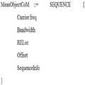
도 4는 측정 오브젝트를 개념적으로 표현한 CoMP 세트 정보의 구성이다.4 is a configuration of CoMP set information conceptually representing a measurement object.
CoMP와 둘 이상의 요소반송파들을 이용하여 통신하는 CA(Carrier Aggregation)은 각 단말에 대하여 동시에 구현될 수 있으며, 또는 각 순간에 둘 중 하나만이 지원될 수도 있다. CoMP와 CA가 동시에 지원되지 않을 경우, CSI 보고 제어를 위한 정보는 CoMP가 수행될 수 있는 단일 대역에 대하여만 정의된다. 따라서 도 4의 (a)에 도시한 바와 같이 CoMP 수행 대역을 지시하는 주파수(carrier frequency) 및 대역(bandwidth), 상기 대역 내에서 단말이 측정 대상으로 삼아야 할 CSI-RS에 대한 구성 정보들의 리스트를 통해 CoMP 세트 정보가 구성될 수 있다.A carrier aggregation (CA) that communicates using CoMP and two or more CCs may be simultaneously implemented for each UE, or only one of the two may be supported at each instant. If CoMP and CA are not supported at the same time, the information for CSI reporting control is defined only for a single band in which CoMP can be performed. Accordingly, as shown in (a) of FIG. 4, a list of configuration information about a frequency and a bandwidth indicating a CoMP execution band and CSI-RS to be measured by the UE within the band is included. CoMP set information may be configured.
반면, 단말이 CA 및 CoMP을 동시에 지원 받거나, 또는 CoMP/CA 간 동적 스위칭(dynamic switching)이 지원되는 경우, 제1송수신 포인트(110)는 도 4의 (b)에 도시한 바와 같이 CoMP 대상이 될 수 있는 각 요소반송파(carrier frequency 1 및 2)에 대하여 CSI-RS 구성 정보를 단말(120)에 전달할 수 있다.On the other hand, if the terminal is supported at the same time CA and CoMP, or if the dynamic switching between CoMP / CA (dynamic switching), the first transmission and
도 5 및 도 6은 CoMP 세트 정보의 측정 오브젝트를 표현하는 방법들에 대한 예들이다.5 and 6 are examples of methods for representing a measurement object of CoMP set information.
도 5를 참조하면 단일 또는 다수의 대역에 대하여 CSI-RS 수신 전력 측정을 지시하며, 하나 또는 각 대역을 설정한 후 각 대역에 대하여 다수의 CSI-RS 설정을 지시하는 방식으로 CoMP 세트 정보가 설정된다.Referring to FIG. 5, CoMP set information is set in a manner of instructing CSI-RS reception power measurement for a single or multiple bands and setting a plurality of CSI-RS for each band after setting one or each band. do.
도 6을 참조하면 각각의 CSI-RS 설정에 대하여 독립적으로 각 대역 및 CSI-RS 전력 측정에 필요한 모든 정보를 지시하는 방식을 사용한다.Referring to FIG. 6, a method of indicating all information necessary for measuring each band and CSI-RS power independently for each CSI-RS configuration is used.
CoMP의 경우, 동일한 대역에서 대단히 많은 수의 CSI-RS 수신을 단말에 지시할 수 있어야 함으로, 도 4 또는 도 5와 같이 각 대역에 대하여 그룹 단위로 다수의 CSI-RS 자원 정보(각 CSI-RS 구성에 대한 CSI-RS RE 정보 및 오프셋 정보 (또는 서브프레임 정보))를 설정할 수 있고, 도 6과 같이 기존 RRM 측정의 구성과 동일하게 각 CSI-RS 자원에 대한 모든 정보를 독립적으로 구성할 수도 있다.In the case of CoMP, since a very large number of CSI-RS reception should be indicated to the UE in the same band, as shown in FIG. 4 or 5, a plurality of CSI-RS resource information (each CSI-RS) is grouped for each band. CSI-RS RE information and offset information (or subframe information)) can be set for the configuration, and as shown in FIG. 6, all information for each CSI-RS resource can be independently configured as in the configuration of the existing RRM measurement. have.
이때 별도의 시그널링을 통해 오브젝트를 추가 또는 제거하므로 상기 정보를 수정하거나 업데이트하므로 단말이 수신 전력을 측정하여야 할 CSI-RS 구성 정보의 변동을 지시할 수도 있다. 예를 들어 측정 오브젝트에 포함되는 정보는 RSToAddList/ RSToRemoveList(수정(추가 또는 제거) 등의 형식으로 수정될 수 있다.In this case, since the object is added or removed through separate signaling, the information may be modified or updated, and thus the UE may indicate a change in the CSI-RS configuration information in which the reception power should be measured. For example, the information included in the measurement object may be modified in a format such as RSToAddList / RSToRemoveList (modify (add or remove).
2. 보고 구성(Reporting configuration)2. Reporting configuration
보고 구성(Reporting configuration)는 단말의 측정값 보고를 지시하는 정보들로 구성되며, 각 정보는 표 2와 같이 다음의 두 가지 요소로 구성된다.Reporting configuration is composed of information indicating the measurement report of the terminal, each information consists of the following two elements as shown in Table 2.
보고 구성(Reporting configuration) 정보로서, CSI-RS의 수신 전력 (RSRP) 보고의 주기에 대한 정보를 포함할 수 있으며, 각 대역별 또는 CSI-RS 별 측정 보고의 주기 또는 오프셋을 별도로 설정하는 정보가 CoMP 세트 정보에 포함될 수 있으나 이에 제한되지 않는다.Reporting configuration information, which may include information on the frequency of the received power (RSRP) reporting of the CSI-RS, and information for separately setting the period or offset of the measurement report for each band or CSI-RS CoMP set information may be included, but is not limited thereto.
보고 구성(Reporting configuration)은 표 2의 정보들의 리스트로 주어진다.Reporting configuration is given as a list of information in Table 2.
3. 측정 ID(Measurement identities)3. Measurement identities
측정 ID(Measurement identities)는 각 측정 오브젝트(measurement object)와 각 보고 구성(reporting configuration) 간 연결(linking)에 대한 정보들이다. 예를 들어 둘 이상의 측정 오브젝트(measurement objects)을 하나의 보고 구성(reporting configuration)와 연결하거나, 또는 둘 이상의 보고 구성(reporting configuration)을 동일 측정 오브젝트(measurement objects)에 연결하는 등의 방식일 수도 있다.Measurement identities are information about linking between each measurement object and each reporting configuration. For example, two or more measurement objects can be linked to one reporting configuration, or two or more reporting configurations can be linked to the same measurement objects. .
측정 ID(Measurement identities)는 상기 정보들의 리스트로 주어진다.Measurement identities are given in the list of information.
4. 측정 간격(Measurement gaps)4. Measurement gaps
측정 간격(Measurement gaps)은 상향링크 또는 하향링크 전송이 스케줄링되지 않아 단말이 측정을 수행할 수 있는 시간 주기를 정의한다. 단말이 CSI-RS 수신 전력 측정을 수행하여야 하는 각 CSI-RS 신호에 대하여, 각기 다른 측정 주기를 설정하거나 또는 동일한 측정 주기를 설정할 수 있다. 별도의 지시가 없을 시 단말은 모든 CSI-RS 신호에 대하여 동일한 주기로 전력 측정을 수행하며, 별도의 지시가 없을 시 특정 주기, 예를 들어 200ms의 주기로 CSI-RS 수신 전력 측정을 수행한다.Measurement gaps define a time period during which the UE can perform measurement because uplink or downlink transmission is not scheduled. For each CSI-RS signal for which the UE should perform CSI-RS reception power measurement, different measurement periods may be set or the same measurement period may be set. When there is no separate instruction, the UE performs power measurement at the same period for all CSI-RS signals. When there is no separate instruction, the UE performs CSI-RS reception power measurement at a specific period, for example, a period of 200 ms.
다음으로 제1송수신 포인트(110)는 CSI-RS를 전송한다(S230). 이때 S230단계에서 제1송수신 포인트(110) 이외에 다른 송수신 포인트들(112, 114, 116)도 CSI-RS를 전송한다. 단말(120)은 둘 이상의 송수신 포인트들로부터 CSI-RS를 수신한다.Next, the first transmission and
단말(120)은 CoMP 세트 정보에 포함된 CSI-RS 구성 정보를 사용하여 둘 이상의 송수신 포인트들의 CSI-RS의 수신 전력들을 측정한다(S240).The terminal 120 measures received powers of the CSI-RSs of two or more transmission / reception points using the CSI-RS configuration information included in the CoMP set information (S240).
단말(120)은 측정결과를 포함하는 그 측정정보를 제1 송수신 포인트(110)에 전송한다(S250). 제1송수신 포인트(110)는 그 측정정보를 수신한다. 단말(120)은 이 측정정보를 상위계층 시스널링, 예를 들어 RRC 시그널링에 의해 제1송수신 포인트(110)에 보고할 수 있다.The terminal 120 transmits the measurement information including the measurement result to the first transmission / reception point 110 (S250). The first transmission /
측정정보로 참조신호 수신전력인 RSRP(Reference Signal Received Power)를 예를 들어 설명하였으나 측정정보는 이에 제한되지 않고 RSSI(Received Signal Strength Indicator), RSRQ(Reference Signal Received Quality) 중 하나일 수도 있다. 또한, CSI-RS 수신 전력으로부터 유도되는 또 다른 값일 수 있으며, 또는 각 CSI-RS 수신 전력 및 다른 CSI-RS 수신 전력에 의해 계산되는 신호 세기와 간섭의 크기에 또는 상대적 크기에 대한 정보일 수 있다.Although reference signal received power (RSRP), which is a reference signal reception power, has been described as measurement information, the measurement information is not limited thereto, and may also be one of a received signal strength indicator (RSSI) and a reference signal received quality (RSRQ). It may also be another value derived from the CSI-RS received power, or may be information about the relative magnitude or the magnitude of the signal strength and interference calculated by each CSI-RS received power and other CSI-RS received power. .
단말(120)은 수신한 CoMP 세트에 대하여 CSI-RS 포트 15 (또는 다수의 포트)에 대하여 수신 전력 측정을 수행하며, 상기 측정된 전력을 (1)주기적으로 네트워크에 보고하거나 (2)비주기적으로 네트워크 요청 시 보고하거나 제1송수신 포인트(110)을 포함하는 네트워크가 CoMP 측정 세트 제어를 위해 CSI-RS 수신 전력 보고를 PDCCH 통해 요청하는 경우 보고하거나 (3)채널 상태에 변화가 있다고 감지되는 경우(특정 이벤트가 발생하는 경우) 네트워크에 보고할 수 있다. 한편 단말이 링크 변화를 감지하여 CoMP 측정 세트의 조율이 필요하다 판단하는 경우 CSI-RS 수신 전력을 보고한다.The terminal 120 performs reception power measurement on the CSI-RS port 15 (or a plurality of ports) with respect to the received CoMP set, and reports the measured power (1) periodically to the network or (2) aperiodically. Report when a network request is made or when a network including the first transmission /
이때 둘 이상의 CSI-RS 수신 전력을 조합하여 하나의 PUSCH을 생성하여 보고할 수 있다. 상기 정보를 보고하여야 할 서브프레임에서 PUSCH 전송이 예정되어 있다면 상기 PUSCH을 누락하고 CSI-RS 수신 정보를 보고하는 방식을 사용할 수 있다.In this case, one PUSCH may be generated and reported by combining two or more CSI-RS received powers. If a PUSCH transmission is scheduled in a subframe in which the information is to be reported, a method of omitting the PUSCH and reporting CSI-RS reception information may be used.
또한 PUSCH 전송에 할당된 무선 자원이 충분히 많다면 상기 CSI-RS 수신 전력 정보를 PUSCH의 일부 영역에 할당하여 전송이 예약된 정보와 상기의 CSI-RS 수신 전력 정보를 동시에 전달할 수도 있다.In addition, if there are enough radio resources allocated for PUSCH transmission, the CSI-RS received power information may be allocated to a partial region of the PUSCH to simultaneously transmit the reserved information and the CSI-RS received power information.
다음으로 제1송수신 포인트(110)는 CoMP 세트에 속하는 송수신 포인트들의 측정정보를 사용하여 측정 세트(measurement set)를 결정한다(S260). 이 측정 세트(measurement set)에 포함되는 송수신 포인트들은 CoMP 세트에 포함되는 송수신 포인트들의 부분집합(subset)에 해당한다. 예를 들어 CoMP 세트에 포함되는 송수신 포인트들이 전술한 제1 내지 제4송수신 포인트(110, 112, 114, 116)이었다면, 측정 세트에 포함되는 송수신 포인트들은 예를 들어 단말로부터 수신한 RSRP(Reference Signal Received Power)가 임계치를 초과하는 제1송수신 포인트(110)과 제4송수신 포인트(116)일 수 있다.Next, the first transmission /
제1송수신 포인트(110)는 측정 세트 정보를 단말(120)에 전송한다(S270). 이 측정 세트 정보는 측정 대상이 측정 세트에 해당하는 송수신 포인트들인 차이점을 제외하고 CoMP 세트 정보와 동일 또는 실질적으로 동일할 수 있다.The first transmission /
단말(120)은 송수신 포인트들로부터 CSI-RS를 수신한다(S280).The terminal 120 receives the CSI-RS from the transmission and reception points (S280).
다음으로 단말(120)은 측정 세트에 해당하는 송수신 포인트들의 CSI-RS를 이용하여 채널상태정보를 측정한다(S285).Next, the terminal 120 measures the channel state information by using the CSI-RS of the transmission and reception points corresponding to the measurement set (S285).
단말(120)은 측정 세트에 해당하는 송수신 포인트들의 채널상태정보들을 제1송수신 포인트(110)에 보고한다(S290).The terminal 120 reports the channel state information of the transmission / reception points corresponding to the measurement set to the first transmission / reception point 110 (S290).
구체적으로 제1송수신포인트(110)가 다수의 채널상태정보의 측정 대상에 대한 정보(예를 들어 CSI-RS 자원 구성 정보)를 단말(120)에 통지하면, 단말(120)은 상기 대상들(결과적으로 송수신 포인트들)에 대한 채널상태정보 각각을 측정한 후, 하향링크 전송에 가장 적합하다고 판단되는 N개의 대상에 대하여 채널상태정보를 보고한다.In detail, when the first transmission /
CoMP 구동을 지원하기 위해, 단말(120)은 다수의 CSI-RS 자원(resource)에 대하여 둘 이상의 채널상태정보를 측정하고 둘 이상의 채널상태정보를 PUCCH/PUSCH 통해 제1송수신포인트(110)에 보고한다.In order to support CoMP driving, the terminal 120 measures two or more channel state information for a plurality of CSI-RS resources and reports the two or more channel state information to the first transmission /
다음으로 적어도 하나의 송수신 포인트와 단말(120)은 협력 통신(전송)하므로 CoMP 구동(동작)한다(S295). CoMP 구동(동작)은 조인트 프로세싱(Joint Processing: JP, 이하 'JP'라 함)과 협력 스케줄링/빔포밍(Coordinated Scheduling/Beamforming: CS/CB, 이하 'CS/CB'라 함)일 수도 있고 JP와 CS/CB를 혼합하는 것일 수도 있다.Next, at least one transmission and reception point and the terminal 120 cooperatively communicate (transmit), thereby driving CoMP (operation) (S295). CoMP operation (operation) may be Joint Processing (JP, hereinafter referred to as JP) and Coordinated Scheduling / Beamforming (CS / CB, hereinafter referred to as `` CS / CB '') or JP It may be a mixture of and CS / CB.
또한, 단말의 CSI-RS 수신 전력 보고를 고려하여 측정 세트 변동이 필요하다고 판단 시 제1송수신 포인트는 이를 단말에 <측정 세트 정보> 로 단말에 통지한다. 또한, CSI-RS 수신 전력을 측정할 CSI-RS 구성에 대한 변동이 필요한 경우, 제1송수신 포인트는 이를 <CoMP 세트 정보>로 단말에 통지한다. 상기의 변경된 정보에 대해 네트워크 및 단말은 도2에 도시한 동작을 수행할 수 있다.In addition, when it is determined that measurement set variation is necessary in consideration of the CSI-RS reception power report of the terminal, the first transmitting / receiving point notifies the terminal to the terminal as <measuring set information>. In addition, when a change to the CSI-RS configuration for measuring the CSI-RS received power is required, the first transmitting / receiving point notifies the terminal of this by <CoMP set information>. The network and the terminal may perform the operation illustrated in FIG. 2 with respect to the changed information.
이상에서는 본 발명의 실시예에 따른 CoMP 세트 및 측정 세트 설정 방법이 도 2에서와 같은 절차로 수행되는 것으로 설명되었으나, 이는 설명의 편의를 위한 것일 뿐, 본 발명의 본질적인 개념을 벗어나지 않는 범위 내에서, 구현 방식에 따라 각 단계의 수행 절차가 바뀌거나 둘 이상의 단계가 통합되거나 하나의 단계가 둘 이상의 단계로 분리되어 수행될 수도 있다.In the above description, the CoMP set and the measurement set setting method according to the embodiment of the present invention have been described as being performed in the same procedure as in FIG. 2, but this is only for convenience of description and within the scope not departing from the essential concept of the present invention. According to the implementation manner, the execution procedure of each step may be changed, two or more steps may be integrated, or one step may be performed in two or more steps.
도 7은 다른 실시예에 따른 단말과 송수신 포인트를 나타내는 블록도이다.7 is a block diagram illustrating a terminal and a transmission / reception point according to another embodiment.
도 7을 참조하면, 송수신 포인트(710)는 도 2를 참조하여 설명한 제1송수신 포인트(110)의 동작을 수행한다. 구체적으로 송수신 포인트(710)는 송수신부(712) 및 CoMP 동작부(714)를 포함한다.Referring to FIG. 7, the transmission /
송수신부(712)는 둘 이상의 송수신 포인트들의 하향링크 채널상태정보 참조신호(Channel State Information Reference Signal) 구성 정보로 구성된 CoMP 세트 정보를 단말(720)에 전송한다. 또한 송수신부(712)는 단말(720)로부터 CoMP 세트에 대한 하향링크 채널상태정보 참조신호 측정 정보를 수신한다.The
송수신부(712)는 측정 세트 정보를 단말(720)에 전송하고 하향링크 채널 상태정보 참조신호(Channel State Information Reference Signal)를 전송한다. 단말(720)로부터 측정 세트에 대한 채널상태정보를 수신한다.The
CoMP 동작부(714)는 CoMP 세트 및/또는 측정 세트를 결정한다. CoMP 동작부(714)는 하향링크 채널상태정보 참조신호(Channel State Information Reference Signal)의 측정정보에 기초하여 CoMP 동작을 수행한다.
단말(720)은 도 2를 참조하여 설명한 단말(120)의 동작을 수행한다. 구체적으로 단말(720)은 송수신부(722) 및 측정부(724)를 포함한다.The terminal 720 performs an operation of the terminal 120 described with reference to FIG. 2. In more detail, the terminal 720 includes a
송수신부(722)는 둘 이상의 송수신 포인트들의 하향링크 채널상태정보 참조신호(Channel State Information Reference Signal) 구성 정보로 구성된 CoMP 세트 정보를 송수신 포인트(710)로부터 수신한다. 송수신부(722)는 하향링크 채널상태정보 참조신호(Channel State Information Reference Signal) 구성 정보를 사용하여 둘 이상의 송수신 포인트들의 하향링크 채널상태정보 참조신호(Channel State Information Reference Signal)를 수신한다. 송수신부(722)는 둘 이상의 송수신 포인트들로부터 수신된 하향링크 채널상태정보 참조신호(Channel State Information Reference Signal)의 측정정보를 송수신 포인트(710)로 전송한다. 송수신부(722)는 송수신 포인트(710)으로부터 측정 세트 정보를 수신하고 측정 세트에 대한 채널 상태 정보를 송수신 포인트(710)로 전송한다.The
측정부(724)는 수신된 하향링크 채널상태정보 참조신호(Channel State Information Reference Signal)에 기초하여 채널상태정보 참조신호(Channel State Information Reference Signal) 측정정보를 형성한다.The
이상 도면을 참조하여 실시예들을 설명하였으나 본 발명은 이에 제한되지 않는다.Although the embodiments have been described with reference to the drawings, the present invention is not limited thereto.
전술한 실시예에서 하향링크 참조신호로 CSI-RS를 예를 들어 설명하였으나 다른 하향링크 참조신호, 예를 들어 DM-RS일 수도 있고 장래 정의되거나 규격화되는 참조신호일 수도 있다.Although the CSI-RS has been described as a downlink reference signal in the above-described embodiment, it may be another downlink reference signal, for example, a DM-RS, or may be a reference signal defined or standardized in the future.
전술한 실시예에서 서빙 셀 또는 매크로 셀에 해당하는 제1송수신 포인트에 대한 CoMP 세트 정보는 참조신호 구성 정보로 CSI-RS 구성 정보 또는 CRS 구성 정보 중 적어도 하나를 포함할 수 있다. 제1송수신 포인트는 CoMP 세트 정보의 참조신호 구성 정보 리스트 중 하나로 CSI-RS 구성 정보 또는 CRS 구성 정보 중 하나를 포함할 수 있다. 예를 들어 제1송수신 포인트는 CoMP 세트 정보의 참조신호 구성 정보 리스트 중 하나로 CRS 포트 0에 대한 정보를 포함할 수 있다.In the above-described embodiment, the CoMP set information of the first transmission / reception point corresponding to the serving cell or the macro cell may include at least one of CSI-RS configuration information and CRS configuration information as reference signal configuration information. The first transmission / reception point is one of reference signal configuration information lists of CoMP set information and may include one of CSI-RS configuration information and CRS configuration information. For example, the first transmission / reception point may include information on
전술한 실시예에서 CSI-RS 수신 전력 측정에 대한 정보를 전달하기 위한 CSI-RS 자원에 대한 정보 및 CSI-RS 측정 지시 정보의 조합으로 구성된 RRC 시스널링을 CoMP 세트 또는 CoMP 세트 정보라고 정의하였으나 본 발명은 전술한 명칭 또는 정의에만 국한되지 않으며, CoMP 측정 제어 세트(measurement control set) 등 다양한 방식으로 명명될 수 있다. 또한 본 발명은 RRC 시스널링들이 별도의 구성 또는 세트(set)로 정의되는 경우에 대하여 설명하였으나 본 발명은 이에 국한되지 않으며, 상기의 시그널링이 다른 RRC 시그널링 구성의 일부분으로 포함될 수도 있다. 예를 들어, CoMP 협력 세트(cooperating set)을 정의함에 있어, 도6에 명시된 정보들이 CoMP 협력 세트(cooperating set)에 포함되어 전달될 수도 있다.In the above-described embodiment, RRC signaling consisting of a combination of CSI-RS resource information and CSI-RS measurement indication information for transmitting information on CSI-RS received power measurement is defined as CoMP set or CoMP set information. The invention is not limited to the above names or definitions, and may be named in various ways, such as a CoMP measurement control set. In addition, the present invention has been described in the case where the RRC signaling is defined in a separate configuration or set, but the present invention is not limited thereto, and the above signaling may be included as part of another RRC signaling configuration. For example, in defining a CoMP cooperating set, the information specified in FIG. 6 may be included in the CoMP cooperating set and transmitted.
이상의 설명은 본 발명의 기술 사상을 예시적으로 설명한 것에 불과한 것으로서, 본 발명이 속하는 기술 분야에서 통상의 지식을 가진 자라면 본 발명의 본질적인 특성에서 벗어나지 않는 범위에서 다양한 수정 및 변형이 가능할 것이다. 따라서, 본 발명에 개시된 실시예들은 본 발명의 기술 사상을 한정하기 위한 것이 아니라 설명하기 위한 것이고, 이러한 실시예에 의하여 본 발명의 기술 사상의 범위가 한정되는 것은 아니다. 본 발명의 보호 범위는 아래의 청구범위에 의하여 해석되어야 하며, 그와 동등한 범위 내에 있는 모든 기술 사상은 본 발명의 권리범위에 포함되는 것으로 해석되어야 할 것이다.The foregoing description is merely illustrative of the technical idea of the present invention, and various changes and modifications may be made by those skilled in the art without departing from the essential characteristics of the present invention. Therefore, the embodiments disclosed in the present invention are intended to illustrate rather than limit the scope of the present invention, and the scope of the technical idea of the present invention is not limited by these embodiments. The protection scope of the present invention should be interpreted by the following claims, and all technical ideas within the equivalent scope should be interpreted as being included in the scope of the present invention.
Claims (10)
Translated fromKorean상기 둘 이상의 송수신 포인트들의 하향링크 참조신호 구성 정보로 구성된 CoMP(coordinated multi-point transmission/reception System) 세트 정보를 상기 단말에 전송하는 단계; 및
상기 CoMP 세트 대한 하향링크 참조신호의 측정정보를 상기 단말로부터 수신하는 단계를 포함하는 송수신 포인트의 CoMP 세트 설정 방법.In a wireless communication system in which two or more transmission and reception points and the terminal cooperative communication,
Transmitting coordinated multi-point transmission / reception system (CoMP) set information including downlink reference signal configuration information of the two or more transmission / reception points to the terminal; And
And receiving measurement information of a downlink reference signal for the CoMP set from the terminal.
상기 하향링크 참조신호는 채널상태정보 참조신호(Channel State Information Reference Signal)인 것을 특징으로 하는 송수신 포인트의 CoMP 세트 설정 방법.The method of claim 1,
And the downlink reference signal is a channel state information reference signal.
상기 하향링크 참조신호 구성 정보는 상기 하향링크 참조신호의 RE 위치 정보 및 시퀀스 정보, 서브프레임 정보 중 하나를 포함하는 것을 특징으로 하는 송수신 포인트의 CoMP 세트 설정 방법.The method of claim 1,
The downlink reference signal configuration information includes one of RE location information, sequence information, and subframe information of the downlink reference signal.
상기 하향링크 참조신호의 측정정보는 상기 하향링크 참조신호의 수신전력인 것을 특징으로 하는 송수신 포인트의 CoMP 세트 설정 방법.The method of claim 1,
And the measurement information of the downlink reference signal is the reception power of the downlink reference signal.
상기 둘 이상의 송수신 포인트들의 하향링크 참조신호 구성 정보로 구성된 CoMP(coordinated multi-point transmission/reception System) 세트 정보를 상기 송수신 포인트들 중 하나로부터 수신하는 단계;
상기 하향링크 참조신호 구성 정보를 사용하여 상기 둘 이상의 송수신 포인트들의 하향링크 참조신호를 수신하는 단계; 및
상기 CoMP 세트에 대한 하향링크 참조신호의 측정정보를 상기 둘 이상의 송수신 포인트들 중 하나로 전송하는 단계를 포함하는 단말의 CoMP 세트 설정 방법.In a wireless communication system in which two or more transmission and reception points and the terminal cooperative communication,
Receiving coordinated multi-point transmission / reception system (CoMP) set information consisting of downlink reference signal configuration information of the two or more transmission / reception points from one of the transmission / reception points;
Receiving a downlink reference signal of the two or more transmission / reception points using the downlink reference signal configuration information; And
Transmitting measurement information of a downlink reference signal for the CoMP set to one of the two or more transmission / reception points.
상기 하향링크 참조신호는 채널상태정보 참조신호(Channel State Information Reference Signal)인 것을 특징으로 하는 단말의 CoMP 세트 설정 방법.The method of claim 5,
And the downlink reference signal is a channel state information reference signal.
상기 하향링크 참조신호 구성 정보는 하향링크 참조신호의 RE 위치 정보 및 시퀀스 정보, 서브프레임 정보 중 하나를 포함하는 것을 특징으로 하는 단말의 CoMP 세트 설정 방법.The method of claim 5,
The downlink reference signal configuration information includes one of RE location information, sequence information, and subframe information of a downlink reference signal.
상기 하향링크 참조신호의 측정정보는 상기 하향링크 참조신호의 수신전력인 것을 특징으로 하는 단말의 CoMP 세트 설정 방법.The method of claim 5,
And the measurement information of the downlink reference signal is a reception power of the downlink reference signal.
상기 둘 이상의 송수신 포인트들의 하향링크 채널상태정보 참조신호(Channel State Information Reference Signal) 구성 정보로 구성된 CoMP(coordinated multi-point transmission/reception System) 세트 정보를 상기 단말에 전송하고, 상기 CoMP 세트에 대한 하향링크 채널상태정보 참조신호(Channel State Information Reference Signal)의 측정정보를 상기 단말로부터 수신하는 송수신부; 및
상기 하향링크 채널상태정보 참조신호(Channel State Information Reference Signal)의 측정정보에 기초하여 CoMP 동작을 수행하는 동작부를 포함하는 송수신 포인트.In a wireless communication system in which two or more transmission and reception points and the terminal cooperative communication,
Coordinated multi-point transmission / reception system (CoMP) set information including downlink channel state information reference signal (CoMP) configuration information of the two or more transmission / reception points is transmitted to the terminal, and downlink of the CoMP set is transmitted. A transceiver for receiving measurement information of a link channel state information reference signal from the terminal; And
And an operation unit configured to perform a CoMP operation based on measurement information of the downlink channel state information reference signal.
상기 둘 이상의 송수신 포인트들의 하향링크 채널상태정보 참조신호(Channel State Information Reference Signal) 구성 정보로 구성된 CoMP(coordinated multi-point transmission/reception System) 세트 정보를 상기 송수신 포인트들 중 하나로부터 수신하고, 상기 하향링크 채널상태정보 참조신호(Channel State Information Reference Signal) 구성 정보를 사용하여 상기 둘 이상의 송수신 포인트들의 하향링크 채널상태정보 참조신호(Channel State Information Reference Signal)를 수신하고, 상기 CoMP 세트에 대한 하향링크 채널상태정보 참조신호(Channel State Information Reference Signal)의 측정정보를 상기 둘 이상의 송수신 포인트들 중 하나로 전송하는 송수신부; 및
상기 수신된 하향링크 채널상태정보 참조신호(Channel State Information Reference Signal)에 기초하여 채널상태정보 참조신호(Channel State Information Reference Signal) 측정정보를 형성하는 측정부를 포함하는 단말.In a wireless communication system in which two or more transmission and reception points and the terminal cooperative communication,
Receiving coordinated multi-point transmission / reception system (CoMP) set information including downlink channel state information reference signal (CoMP) configuration information of the two or more transmission / reception points from one of the transmission / reception points, and receiving the downlink Receives downlink channel state information reference signals of the two or more transmission / reception points by using link channel state information reference signal configuration information, and provides a downlink channel for the CoMP set. A transceiver for transmitting measurement information of a channel state information reference signal to one of the two or more transmission / reception points; And
And a measurement unit configured to form channel state information reference signal measurement information based on the received downlink channel state information reference signal.
Priority Applications (1)
| Application Number | Priority Date | Filing Date | Title |
|---|---|---|---|
| KR1020120009274AKR20130087973A (en) | 2012-01-30 | 2012-01-30 | Method for setting comp set, point and user equipment thereof in coordinated multi-point transmission/reception system |
Applications Claiming Priority (1)
| Application Number | Priority Date | Filing Date | Title |
|---|---|---|---|
| KR1020120009274AKR20130087973A (en) | 2012-01-30 | 2012-01-30 | Method for setting comp set, point and user equipment thereof in coordinated multi-point transmission/reception system |
Publications (1)
| Publication Number | Publication Date |
|---|---|
| KR20130087973Atrue KR20130087973A (en) | 2013-08-07 |
Family
ID=49214524
Family Applications (1)
| Application Number | Title | Priority Date | Filing Date |
|---|---|---|---|
| KR1020120009274AWithdrawnKR20130087973A (en) | 2012-01-30 | 2012-01-30 | Method for setting comp set, point and user equipment thereof in coordinated multi-point transmission/reception system |
Country Status (1)
| Country | Link |
|---|---|
| KR (1) | KR20130087973A (en) |
Cited By (3)
| Publication number | Priority date | Publication date | Assignee | Title |
|---|---|---|---|---|
| US9419696B2 (en) | 2011-12-19 | 2016-08-16 | Comcast Cable Communications, Llc | Beam information exchange between base stations |
| US10085165B2 (en) | 2011-09-23 | 2018-09-25 | Comcast Cable Communications, Llc | Multi-cell signals in OFDM wireless networks |
| US12445912B2 (en) | 2022-05-11 | 2025-10-14 | Comcast Cable Communications, Llc | Beamforming in wireless communications |
- 2012
- 2012-01-30KRKR1020120009274Apatent/KR20130087973A/ennot_activeWithdrawn
Cited By (36)
| Publication number | Priority date | Publication date | Assignee | Title |
|---|---|---|---|---|
| US10085165B2 (en) | 2011-09-23 | 2018-09-25 | Comcast Cable Communications, Llc | Multi-cell signals in OFDM wireless networks |
| US12250584B2 (en) | 2011-09-23 | 2025-03-11 | Comcast Cable Communications, Llc | Multi-cell signals in OFDM wireless networks |
| US11871262B2 (en) | 2011-09-23 | 2024-01-09 | Comcast Cable Communications, Llc | Multi-cell signals in OFDM wireless networks |
| US11611897B2 (en) | 2011-09-23 | 2023-03-21 | Comcast Cable Communications, Llc | Multi-cell signals in OFDM wireless networks |
| US11432180B2 (en) | 2011-09-23 | 2022-08-30 | Comcast Cable Communications, Llc | Multi-cell signals in OFDM wireless networks |
| US10917807B2 (en) | 2011-09-23 | 2021-02-09 | Comcast Cable Communications, Llc | Multi-cell signals in OFDM wireless networks |
| US10667164B2 (en) | 2011-09-23 | 2020-05-26 | Comcast Cable Communications, Llc | Multi-cell signals in OFDM wireless networks |
| US10306506B2 (en) | 2011-09-23 | 2019-05-28 | Comcast Cable Communications, Llc | Multi-cell signals in OFDM wireless networks |
| US10715228B2 (en) | 2011-12-19 | 2020-07-14 | Comcast Cable Communications, Llc | Beamforming signaling in a wireless network |
| US10966124B2 (en) | 2011-12-19 | 2021-03-30 | Comcast Cable Communications, Llc | Beamforming codeword exchange between base stations |
| US10181883B2 (en) | 2011-12-19 | 2019-01-15 | Comcast Cable Communications, Llc | Beamforming signaling in a wireless network |
| US10193605B2 (en) | 2011-12-19 | 2019-01-29 | Comcast Cable Communications, Llc | Beamforming codeword exchange between base stations |
| US10236956B2 (en) | 2011-12-19 | 2019-03-19 | Comcast Cable Communications, Llc | Beamforming handover messaging in a wireless network |
| US9917625B2 (en) | 2011-12-19 | 2018-03-13 | Comcast Cable Communications, Llc | Handover signaling for beamforming communications |
| US10530438B2 (en) | 2011-12-19 | 2020-01-07 | Comcast Cable Communications, Llc | Beamforming handover messaging in a wireless network |
| US10530439B2 (en) | 2011-12-19 | 2020-01-07 | Comcast Cable Communications, Llc | Beamforming handover messaging in a wireless network |
| US10601476B2 (en) | 2011-12-19 | 2020-03-24 | Comcast Cable Communications, Llc | Beam information exchange between base stations |
| US9826442B2 (en) | 2011-12-19 | 2017-11-21 | Comcast Cable Communications, Llc | Beam information exchange between base stations |
| US9419696B2 (en) | 2011-12-19 | 2016-08-16 | Comcast Cable Communications, Llc | Beam information exchange between base stations |
| US10804987B2 (en) | 2011-12-19 | 2020-10-13 | Comcast Cable Communications, Llc | Beamforming handover messaging in a wireless network |
| US9788244B2 (en) | 2011-12-19 | 2017-10-10 | Comcast Cable Communications, Llc | Beamforming signaling in a wireless network |
| US9917624B2 (en) | 2011-12-19 | 2018-03-13 | Comcast Cable Communications, Llc | Beamforming handover messaging in a wireless network |
| US10966125B2 (en) | 2011-12-19 | 2021-03-30 | Comcast Cable Communications, Llc | Beam information exchange between base stations |
| US11082896B2 (en) | 2011-12-19 | 2021-08-03 | Comcast Cable Communications, Llc | Beamforming signaling in a wireless network |
| US11375414B2 (en) | 2011-12-19 | 2022-06-28 | Comcast Cable Communications, Llc | Beamforming in wireless communications |
| US9680544B2 (en) | 2011-12-19 | 2017-06-13 | Comcast Cable Communications, Llc | Beamforming codeword exchange between base stations |
| US11510113B2 (en) | 2011-12-19 | 2022-11-22 | Comcast Cable Communications, Llc | Beamforming handover messaging in a wireless network |
| US11516713B2 (en) | 2011-12-19 | 2022-11-29 | Comcast Cable Communications, Llc | Beamforming handover messaging in a wireless network |
| US9455775B2 (en) | 2011-12-19 | 2016-09-27 | Comcast Cable Communications, Llc | Handover signaling for beamforming communications |
| US11647430B2 (en) | 2011-12-19 | 2023-05-09 | Comcast Cable Communications, Llc | Signaling in a wireless network |
| US9450656B2 (en) | 2011-12-19 | 2016-09-20 | Comcast Cable Communications, Llc | Beamforming handover messaging in a wireless network |
| US11950145B2 (en) | 2011-12-19 | 2024-04-02 | Comcast Cable Communications, Llc | Beamforming in wireless communications |
| US12185168B2 (en) | 2011-12-19 | 2024-12-31 | Comcast Cable Communications, Llc | Beamforming handover messaging in a wireless network |
| US9444535B2 (en) | 2011-12-19 | 2016-09-13 | Comcast Cable Communications, Llc | Beamforming signaling in a wireless network |
| US12335798B2 (en) | 2011-12-19 | 2025-06-17 | Comcast Cable Communications, Llc | Beamforming in wireless communications |
| US12445912B2 (en) | 2022-05-11 | 2025-10-14 | Comcast Cable Communications, Llc | Beamforming in wireless communications |
Similar Documents
| Publication | Publication Date | Title |
|---|---|---|
| US11882063B2 (en) | Terminal and reception power measurement method | |
| US11297521B2 (en) | Determining and sending a measurement result performed per beam | |
| US11678206B2 (en) | Terminal, base station and radio communication method using a plurality of synchronization signal blocks | |
| EP3713281B1 (en) | Measurement methods, csi-rs resource sharing methods and apparatuses | |
| US8861430B2 (en) | Methods of point association for cooperative multiple point transmission | |
| EP3402087B1 (en) | Method for reporting channel state information, user equipment, and base station | |
| EP3190820B1 (en) | Method and apparatus for channel quality estimation in consideration of interference control and coordinated communication in cellular system | |
| US9544793B2 (en) | Radio communication system and method | |
| WO2012124552A1 (en) | Channel state information feedback method, user equipment and base station | |
| JP6161347B2 (en) | User terminal, radio base station, and radio communication method | |
| US9820249B2 (en) | Radio base stations and user terminal for synchronization in an asynchronous network | |
| KR20200139784A (en) | System and method for providing time domain assignments in a communication system | |
| KR101678445B1 (en) | Method and device for transmitting and receiving channel state information in wireless communication system | |
| KR20130087972A (en) | Method for rrm measurement, point and user equipment thereof in coordinated multi-point transmission/reception system | |
| US20200267804A1 (en) | User equipment performing beam reporting | |
| KR20130087973A (en) | Method for setting comp set, point and user equipment thereof in coordinated multi-point transmission/reception system |
Legal Events
| Date | Code | Title | Description |
|---|---|---|---|
| PA0109 | Patent application | Patent event code:PA01091R01D Comment text:Patent Application Patent event date:20120130 | |
| PG1501 | Laying open of application | ||
| N231 | Notification of change of applicant | ||
| PN2301 | Change of applicant | Patent event date:20160801 Comment text:Notification of Change of Applicant Patent event code:PN23011R01D | |
| PC1203 | Withdrawal of no request for examination | ||
| WITN | Application deemed withdrawn, e.g. because no request for examination was filed or no examination fee was paid |