KR20130086909A - Pressure sensor and apparatus for sensing a pressure and touch screen including the same - Google Patents
Pressure sensor and apparatus for sensing a pressure and touch screen including the sameDownload PDFInfo
- Publication number
- KR20130086909A KR20130086909AKR1020120034122AKR20120034122AKR20130086909AKR 20130086909 AKR20130086909 AKR 20130086909AKR 1020120034122 AKR1020120034122 AKR 1020120034122AKR 20120034122 AKR20120034122 AKR 20120034122AKR 20130086909 AKR20130086909 AKR 20130086909A
- Authority
- KR
- South Korea
- Prior art keywords
- pressure
- layer
- optical waveguide
- light
- waveguide layer
- Prior art date
- Legal status (The legal status is an assumption and is not a legal conclusion. Google has not performed a legal analysis and makes no representation as to the accuracy of the status listed.)
- Withdrawn
Links
Images


Classifications
- G—PHYSICS
- G01—MEASURING; TESTING
- G01L—MEASURING FORCE, STRESS, TORQUE, WORK, MECHANICAL POWER, MECHANICAL EFFICIENCY, OR FLUID PRESSURE
- G01L1/00—Measuring force or stress, in general
- G01L1/24—Measuring force or stress, in general by measuring variations of optical properties of material when it is stressed, e.g. by photoelastic stress analysis using infrared, visible light, ultraviolet
- G01L1/241—Measuring force or stress, in general by measuring variations of optical properties of material when it is stressed, e.g. by photoelastic stress analysis using infrared, visible light, ultraviolet by photoelastic stress analysis
- G—PHYSICS
- G06—COMPUTING OR CALCULATING; COUNTING
- G06F—ELECTRIC DIGITAL DATA PROCESSING
- G06F3/00—Input arrangements for transferring data to be processed into a form capable of being handled by the computer; Output arrangements for transferring data from processing unit to output unit, e.g. interface arrangements
- G06F3/01—Input arrangements or combined input and output arrangements for interaction between user and computer
- G06F3/03—Arrangements for converting the position or the displacement of a member into a coded form
- G06F3/041—Digitisers, e.g. for touch screens or touch pads, characterised by the transducing means
- G06F3/0412—Digitisers structurally integrated in a display
- G—PHYSICS
- G06—COMPUTING OR CALCULATING; COUNTING
- G06F—ELECTRIC DIGITAL DATA PROCESSING
- G06F3/00—Input arrangements for transferring data to be processed into a form capable of being handled by the computer; Output arrangements for transferring data from processing unit to output unit, e.g. interface arrangements
- G06F3/01—Input arrangements or combined input and output arrangements for interaction between user and computer
- G06F3/03—Arrangements for converting the position or the displacement of a member into a coded form
- G06F3/041—Digitisers, e.g. for touch screens or touch pads, characterised by the transducing means
- G06F3/0414—Digitisers, e.g. for touch screens or touch pads, characterised by the transducing means using force sensing means to determine a position
- G06F3/04144—Digitisers, e.g. for touch screens or touch pads, characterised by the transducing means using force sensing means to determine a position using an array of force sensing means
- G—PHYSICS
- G06—COMPUTING OR CALCULATING; COUNTING
- G06F—ELECTRIC DIGITAL DATA PROCESSING
- G06F2203/00—Indexing scheme relating to G06F3/00 - G06F3/048
- G06F2203/041—Indexing scheme relating to G06F3/041 - G06F3/045
- G06F2203/04105—Pressure sensors for measuring the pressure or force exerted on the touch surface without providing the touch position
Landscapes
- Engineering & Computer Science (AREA)
- General Engineering & Computer Science (AREA)
- Theoretical Computer Science (AREA)
- Physics & Mathematics (AREA)
- General Physics & Mathematics (AREA)
- Human Computer Interaction (AREA)
- Measuring Fluid Pressure (AREA)
Abstract
Translated fromKoreanDescription
Translated fromKorean본 발명은 전자기기와 연동하여 압력을 측정할 수 있는 필름 또는 패널에 관한 것이다. 보다 상세하게는 터치스크린에서 압력을 측정하는 기술에 관한 것이다. The present invention relates to a film or panel capable of measuring pressure in conjunction with an electronic device. More specifically, the present invention relates to a technology for measuring pressure in a touch screen.
종래에는 터치 스크린 하단에 압력센서를 장착하거나 외부의 장치를 이용하여 접촉에 따른 압력을 측정하는 방법 등이 있었다. 선행특허(츨원번호: 2008-0092059)의 경우 스크린 하단에 압력센서를 장착함으로써 터치스크린 조작시 압력을 측정하거나 또는 외부의 터치압력감지 펜을 이용하여 압력을 측정하였다. 그러나 이러한 방법의 경우 압력센서가 터치 스크린 하단에 위치 함으로써 직접적인 압력 측정이 불가능 하였으며, 동시에 여러 위치의 압력이 있는 경우 그 위치와 압력 값을 정확히 측정하는 것이 어려웠다. Conventionally, there has been a method of measuring a pressure according to contact by using a pressure sensor at the bottom of the touch screen or using an external device. In the case of the prior patent (application number: 2008-0092059) by mounting a pressure sensor at the bottom of the screen to measure the pressure when operating the touch screen or by using an external touch pressure sensing pen. In this case, however, the pressure sensor was located at the bottom of the touch screen, so it was impossible to measure the pressure directly.
본 발명은 상기 종래 기술의 문제를 해결하기 위하여 안출된 것으로서, 투명한 필름형 압력센서를 스크린 상단에 설치하여 직접적인 압력 측정 효과를 높일 뿐 아니라 동시에 여러 군데 압력 입력이 있어도 정확한 위치와 압력값을 측정할 수 있는 장치를 제공하는 것을 목적으로 한다.The present invention has been made in order to solve the problems of the prior art, by installing a transparent film-type pressure sensor on the top of the screen to increase the direct pressure measurement effect, at the same time can measure the exact position and pressure value even if there are several pressure inputs It is an object to provide a device that can.
또한 단일 압력센서가 위치와 압력을 동시에 측정할 수 있게 할 뿐 아니라, 압력특정부위에 전기적 배선이 없이 빛이 이동하는 경로만 제공하므로, 전하량 변화를 측정하는 방식에 비하여 설계가 용이한 장치를 제공하는 것을 목적으로 한다.In addition, a single pressure sensor can measure the position and pressure at the same time, as well as provide a path of light movement without electrical wiring on the pressure specific point, providing a device that is easier to design than the method of measuring the change in charge amount It aims to do it.
상기 기술적 과제를 해결하기 위한 본 실시예에 따른 압력 센서는 빛을 발생시키는 광원부; 상기 광원부에서 발생된 상기 빛을 수광부로 전달하는 광도파로; 및 상기 광도파로(Optical waveguide)를 통해 전달된 빛을 수신하는 수광부를 포함하고, 상기 광도파로는 압력에 따라 상기 광도파로를 통해 전달되는 빛의 광량을 조절하는 압력감지부를 포함하는 것이 바람직하다.Pressure sensor according to the present embodiment for solving the technical problem is a light source for generating light; An optical waveguide for transmitting the light generated by the light source unit to the light receiving unit; And it includes a light receiving unit for receiving the light transmitted through the optical waveguide (Optical waveguide), the optical waveguide preferably comprises a pressure sensing unit for adjusting the amount of light transmitted through the optical waveguide in accordance with the pressure.
상기 압력감지부는 상기 압력이 가해지는 가압층; 및 상기 빛이 통과하는 광도파로층을 포함하고, 상기 수광부는 상기 가압층과 상기 광도파로층의 굴절률의 차이에 따른 상기 발생된 빛과 상기 전달된 빛의 광량 변화를 통해 압력을 감지하는 것이 바람직하다.The pressure sensing unit is a pressure layer to which the pressure is applied; And an optical waveguide layer through which the light passes, and the light receiving unit senses a pressure through a change in the amount of light of the generated light and the transmitted light according to a difference in refractive index between the pressure layer and the optical waveguide layer. Do.
상기 압력감지부의 상기 가압층과 상기 광도파로층은 이격되어 형성되고, 상기 가압층은 상기 가압층에 가해진 압력으로 인해 상기 이격되어 있던 광도파로층과 접촉하는 것이 바람직하다.The pressure sensing part and the optical waveguide layer are formed to be spaced apart from each other, and the pressure layer preferably contacts the optical waveguide layer spaced apart due to the pressure applied to the pressure layer.
상기 광도파로층을 통과하는 상기 빛은, 상기 가해진 압력으로 인한 상기 이격되어 있던 상기 가압층과 상기 광도파로층의 접촉에 따라 상기 가압층으로 굴절 또는 산란 또는 흡수되는 것이 바람직하다.Preferably, the light passing through the optical waveguide layer is refracted, scattered, or absorbed into the pressured layer according to the contact between the spaced apart pressurized layer and the optical waveguide layer due to the applied pressure.
상기 가압층과 상기 광도파로층의 상기 굴절률의 차이는 상기 가압층의 굴절률이 상기 광도파로층의 굴절률과 같거나 높은 것이 바람직하다.The difference between the refractive index of the pressing layer and the optical waveguide layer is preferably that the refractive index of the pressing layer is equal to or higher than the refractive index of the optical waveguide layer.
상기 가압층과 상기 광도파로층의 접촉 면적은 상기 가압층에 가해지는 상기 압력의 크기에 따라 변화하며, 상기 굴절 또는 산란 또는 흡수 되는 빛의 광량은 상기 접촉 면적에 따라 변화하는 것이 바람직하다.The contact area between the pressure layer and the optical waveguide layer is changed according to the magnitude of the pressure applied to the pressure layer, and the light amount of the refracted or scattered or absorbed light is preferably changed according to the contact area.
상기 압력감지부는 상기 광도파로층을 통과하는 상기 빛의 굴절 또는 산란 또는 흡수를 방지하며, 상기 가압층과 상기 광도파로층을 이격시키는 지지층; 및 상기 지지층과 상기 광도파로층을 통과하는 상기 빛의 굴절 또는 산란 또는 흡수를 방지하는 기저층을 더 포함한다.The pressure sensing unit prevents refraction, scattering, or absorption of the light passing through the optical waveguide layer, and a support layer spaced apart from the pressure layer and the optical waveguide layer; And a base layer that prevents refraction, scattering, or absorption of the light passing through the support layer and the optical waveguide layer.
상기 가압층은, 상기 지지층으로 이격되어 있는 상기 가압층과 상기 광도파로층의 공간으로 돌출되어 상기 압력으로 인해 상기 광도파로층과 접촉하는 돌출부를 더 포함한다.The pressing layer further includes a protrusion projecting into the space of the pressing layer and the optical waveguide layer spaced apart from the support layer to contact the optical waveguide layer due to the pressure.
상기 지지층 및 상기 기저층의 굴절률은 상기 광도파로층의 굴절률보다 낮은 것이 바람직하다.The refractive index of the support layer and the base layer is preferably lower than the refractive index of the optical waveguide layer.
상기 기술적 과제를 해결하기 위한 본 실시예에 따른 압력 감지 장치는 압력이 가해지는 가압층; 및 빛이 통과하는 광도파로층을 포함하고, 상기 가압층과 상기 광도파로층의 굴절률의 차이에 따른 상기 발생된 빛의 광량 변화를 통해 압력을 감지하는 것이 바람직하다.Pressure sensing apparatus according to the present embodiment for solving the technical problem is a pressure layer is applied pressure; And an optical waveguide layer through which light passes, and sensing pressure through a change in the amount of light generated according to a difference in refractive index between the pressure layer and the optical waveguide layer.
상기 압력감지부의 상기 가압층과 상기 광도파로층은 이격되어 형성되고, 상기 가압층은 상기 가압층에 가해진 압력으로 인해 상기 이격되어 있던 광도파로층과 접촉하는 것이 바람직하다.The pressure sensing part and the optical waveguide layer are formed to be spaced apart from each other, and the pressure layer preferably contacts the optical waveguide layer spaced apart due to the pressure applied to the pressure layer.
상기 광도파로층을 통과하는 상기 빛은, 상기 가해진 압력으로 인한 상기 이격되어 있던 상기 가압층과 상기 광도파로층의 접촉에 따라 상기 가압층으로 굴절 또는 산란 또는 흡수되는 것이 바람직하다.Preferably, the light passing through the optical waveguide layer is refracted, scattered, or absorbed into the pressured layer according to the contact between the spaced apart pressurized layer and the optical waveguide layer due to the applied pressure.
상기 가압층과 상기 광도파로층의 상기 굴절률의 차이는 상기 가압층의 굴절률이 상기 광도파로층의 굴절률과 같거나 높은 것이 바람직하다.The difference between the refractive index of the pressing layer and the optical waveguide layer is preferably that the refractive index of the pressing layer is equal to or higher than the refractive index of the optical waveguide layer.
상기 가압층과 상기 광도파로층의 접촉 면적은 상기 가압층에 가해지는 상기 압력의 크기에 따라 변화하며, 상기 굴절 또는 산란 또는 흡수 되는 빛의 광량은 상기 접촉 면적에 따라 변화하는 것이 바람직하다.The contact area between the pressure layer and the optical waveguide layer is changed according to the magnitude of the pressure applied to the pressure layer, and the light amount of the refracted or scattered or absorbed light is preferably changed according to the contact area.
상기 압력감지부는 상기 광도파로층을 통과하는 상기 빛의 굴절 또는 산란 또는 흡수를 방지하며, 상기 가압층과 상기 광도파로층을 이격시키는 지지층; 및 상기 지지층과 상기 광도파로층을 통과하는 상기 빛의 굴절 또는 산란 또는 흡수를 방지하는 기저층을 더 포함하는 것이 바람직하다.The pressure sensing unit prevents refraction, scattering, or absorption of the light passing through the optical waveguide layer, and a support layer spaced apart from the pressure layer and the optical waveguide layer; And a base layer which prevents refraction, scattering, or absorption of the light passing through the support layer and the optical waveguide layer.
상기 가압층은, 상기 지지층으로 이격되어 있는 상기 가압층과 상기 광도파로층의 공간으로 돌출되어 상기 압력으로 인해 상기 광도파로층과 접촉하는 돌출부를 더 포함한다.The pressing layer further includes a protrusion projecting into the space of the pressing layer and the optical waveguide layer spaced apart from the support layer to contact the optical waveguide layer due to the pressure.
상기 지지층 및 상기 기저층의 굴절률은 상기 광도파로층의 굴절률보다 낮은 것이 바람직하다.The refractive index of the support layer and the base layer is preferably lower than the refractive index of the optical waveguide layer.
상기 기술적 과제를 해결하기 위한 본 실시예에 따른 터치 스크린은 터치 입력을 인식하여 상기 터치 입력의 위치를 인식하는 터치 센서; 및광원부에서 발생되어 광도파로(Optical waveguide)를 통해 수광부로 전달된 빛의 광량을 이용하여 상기 터치 입력의 압력을 감지하는 압력 센서를 포함한다. Touch screen according to the present embodiment for solving the technical problem is a touch sensor for recognizing the touch input to recognize the location of the touch input; And a pressure sensor configured to sense a pressure of the touch input by using an amount of light generated by the light source unit and transmitted to the light receiving unit through an optical waveguide.
상기 압력 센서는, 빛을 발생시키는 광원부; 상기 광원부에서 발생된 상기 빛을 수광부로 전달하는 광도파로(Optical waveguide); 및 상기 광도파로를 통해 전달된 빛을 수신하는 수광부를 포함하고, 상기 광도파로는 압력에 따라 상기 광도파로를 통해 전달되는 빛의 광량을 조절하는 압력감지부를 포함한다.The pressure sensor may include a light source unit generating light; An optical waveguide for transmitting the light generated by the light source unit to the light receiving unit; And a light receiving unit configured to receive light transmitted through the optical waveguide, wherein the optical waveguide includes a pressure sensing unit that adjusts an amount of light transmitted through the optical waveguide according to pressure.
상기 압력감지부는 상기 압력이 가해지는 가압층; 및 상기 빛이 통과하는 광도파로층을 포함하고, 상기 수광부는 상기 가압층과 상기 광도파로층의 굴절률의 차이에 따른 상기 발생된 빛과 상기 전달된 빛의 광량 변화를 통해 압력을 감지하는 것이 바람직하다.The pressure sensing unit is a pressure layer to which the pressure is applied; And an optical waveguide layer through which the light passes, and the light receiving unit senses a pressure through a change in the amount of light of the generated light and the transmitted light according to a difference in refractive index between the pressure layer and the optical waveguide layer. Do.
상기 압력감지부의 상기 가압층과 상기 광도파로층은 이격되어 형성되고, 상기 가압층은 상기 가압층에 가해진 압력으로 인해 상기 이격되어 있던 광도파로층과 접촉하는 것이 바람직하다.The pressure sensing part and the optical waveguide layer are formed to be spaced apart from each other, and the pressure layer preferably contacts the optical waveguide layer spaced apart due to the pressure applied to the pressure layer.
본 발명에 따르면 전기적 배선이 없이 광량을 통하여 압력을 감지하도록 하여 설계 및 제작이 용이하며, 광투과성이 좋은 재질을 이용하여 제작함으로써 스크린 상단에 직접 설치가 가능하며, 이에 따라 보다 정확한 압력의 측정이 가능하다. 나아가 압력이 가해진 위치를 인식하는 터치 센서와 함께 터치 스크린에 적용하는 경우 압력의 세기와 가해진 위치를 인식하여, 압력을 이용한 필기감의 구현 및 다양한 사실적인 조작이 가능하다.According to the present invention, it is easy to design and manufacture by sensing the pressure through the amount of light without electrical wiring, it is possible to install directly on the top of the screen by using a light-transmissive material, so that more accurate pressure measurement It is possible. Furthermore, when applied to the touch screen together with a touch sensor that recognizes the position of the pressure is applied to recognize the strength and the position of the pressure, it is possible to implement the writing feeling using the pressure and various realistic manipulation.
도 1은 본 발명의 일실시예에 따른 압력 센서의 구조를 나타내는 도이다.
도 2는 본 발명의 일실시예에 따른 압력 센서의 압력 감지부를 나타내는 도이다.
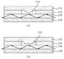
도 3은 본 발명의 일실시예에 따른 압력 센서의 압력 감지부 단면을 나타내는 도이다.
도 4a, 도 4b는 본 발명의 일실시예에 따른 압력 센서의 압력 감지부의 압력 감지 원리를 예시하는 예시도이다.
도 5는 본 발명의 일실시예에 따른 압력 센서의 압력 감지부의 돌출부의 변형예를 나타내는 예시도이다.
도 6은 본 발명의 일실시예에 따른 압력 센서의 압력 감지부의 변형예를 나타내는 예시도이다.
도 7은 본 발명의 일실시예에 따른 단일 광원 및 센서를 이용하는 압력 센서의 구조를 나타내는 도이다.
도 8은 본 발명의 일실시예에 따른 압력 센서를 구비하는 터치센서의 구조를 나타내는 도이다.
도 9는 본 발명의 일실시예에 따른 압력 센서를 이용하여 필체를 구현하는 예를 나타내는 예시도이다.1 is a view showing the structure of a pressure sensor according to an embodiment of the present invention.
2 is a view showing a pressure sensing unit of the pressure sensor according to an embodiment of the present invention.
3 is a cross-sectional view of the pressure sensing unit of the pressure sensor according to the exemplary embodiment of the present invention.
4A and 4B are exemplary views illustrating a pressure sensing principle of a pressure sensing unit of a pressure sensor according to an embodiment of the present invention.
5 is an exemplary view showing a modification of the protrusion of the pressure sensing unit of the pressure sensor according to an embodiment of the present invention.
6 is an exemplary view showing a modification of the pressure sensing unit of the pressure sensor according to an embodiment of the present invention.
7 is a diagram illustrating a structure of a pressure sensor using a single light source and a sensor according to an embodiment of the present invention.
8 is a view showing the structure of a touch sensor having a pressure sensor according to an embodiment of the present invention.
9 is an exemplary view showing an example of implementing a handwriting using a pressure sensor according to an embodiment of the present invention.
이하에서는 도면을 참조하여 본 발명의 바람직한 실시예들을 상세히 설명한다. 이하 설명 및 첨부된 도면들에서 실질적으로 동일한 구성요소들은 각각 동일한 부호들로 나타냄으로써 중복 설명을 생략하기로 한다. 또한 본 발명을 설명함에 있어 관련된 공지기능 혹은 구성에 대한 구체적인 설명이 본 발명의 요지를 불필요하게 흐릴 수 있다고 판단되는 경우 그에 대한 상세한 설명은 생략하기로 한다.Hereinafter, preferred embodiments of the present invention will be described in detail with reference to the drawings. In the following description and the accompanying drawings, substantially the same components are denoted by the same reference numerals, and redundant description will be omitted. In the following description of the present invention, a detailed description of known functions and configurations incorporated herein will be omitted when it may make the subject matter of the present invention rather unclear.
도 1은 본 발명의 일실시예에 따른 압력 센서(10)의 구조를 나타내는 도이다. 도 1을 참조하면, 본 실시예에 따른 압력 센서(10)는 광원부(100), 광도파로(200), 수광부(300)를 포함한다. 또한 광도파로(200)는 압력 감지부(210)를 더 포함한다.1 is a view showing the structure of a
광원부(100)는 빛을 발생시키는 것으로 빛을 발생시켜 광도파로(200)로 빛을 입력시키는 소스 역할을 하며, 빛을 발생시키는 다양한 소자를 사용하는 것이 가능하며, 본 발명에서 목적으로 하는 투명압력센서에 적용할 경우에는 빛이 눈에 보이지 않도록 적외선 광원을 이용하는 것이 바람직하다.The
광도파로(200)는 광원부(100)에서 발생된 상기 빛을 수광부(300)로 전달하며, 압력 센서(10)의 기저부 내부에 설계되어 빛이 지나가는 통로로써 일반적으로 광도파로(200)를 구성하는 물질의 광굴절률이 기저부 물질의 굴절률 보다 높을 경우, 광도파로(200) 물질과 기저물질이 모두 투명하다고 할지라도 광도파로(200)로 들어온 빛이 기저부로 새어나가지 않고 광도파로(200)를 따라서만 이동하게 되는 특징이 있다.The
수광부(300)는 광원부(100)에서 발생되어 광도파로(200)를 통해 전달된 빛의 광량 변화를 통해 압력을 감지하며, 광도파로(200)(Optical waveguide)를 통해 전달된 빛의 광량을 측정한다. 광도파로(200)와 압력감지부를 통과하여 온 빛을 측정하는 센서로써, 기저부에 분포되어있는 다수의 압력 감지부(210)에서 변화된 광량을 개별적으로 측정한다. 이때 다양한 곳의 개별적 압력을 측정하기 위하여 압력감지부의 수가 많을 경우 광도파로(200)도 복잡하게 배치되게 되는데, 일반적으로 광도파로(200)의 크기는 수십마이크로미터 이하의 수준이므로 높은 공간 분해능을 갖은 압력센서를 구성하는데 공간적인 문제는 없다. 그러나 수광부(300)의 경우 압력감지부의 수만큼 광도파로(200)의 출력 값을 개별적으로 측정하여야 하므로, 광센서를 다수 배치하는 방법 외에도 CCD나 CMOS등 이미지센서(106)를 활용하여 개별 출력을 한번에 측정하는 것도 가능하다. 이하 본 실시예에 따른 압력 센서(10)의 압력 감지부(210)에 대해 설명한다.The
압력 감지부(210)는 압력에 따라 상기 광도파로(200)를 통해 전달되는 빛의 광량을 조절하며, 도 2를 참조하면 압력감지부의 하단으로 광도파로(200)가 통과한다. 압력감지부는 압력에 따라 광도파로(200)와 접촉상태를 달리하여 광도파로(200)를 통해 전달되는 빛의 광량을 조절하는 것으로 이하 도면을 통해 보다 상세히 설명한다.The
도 3은 본 발명의 일실시예에 따른 압력 센서(10)의 압력 감지부(210)의 단면도를 나타내는 도이다. 도 3을 참조하면 본 실시예에 따른 압력 감지부(210)는 가압층(212), 광도파로층(216), 지지층(214), 기저층(218)을 포함한다.3 is a diagram illustrating a cross-sectional view of the
가압층(212)은 압력이 가해지는 곳으로, 가압층(212)에 압력이 가해지는 압력에 의해 가압층(212)이 아래로 이동하면서 광도파로층(216)과 접촉하게 된다. 광도파로층(216)은 빛이 통과하는 것으로 광원부(100)에서 발생하는 빛이 실질적으로 통과하는 부분이다.The
또한 본 실시예에서 가압층(212)은 지지층(214)으로 이격되어 있는 가압층(212)과 광도파로층(216)의 공간으로 돌출되어 압력으로 인해 광도파로층(216)과 접촉하는 돌출부(213)를 더 포함할 수 있다.In addition, in the present exemplary embodiment, the
지지층(214)은 광도파로층(216)을 통과하는 빛의 굴절 또는 산란 또는 흡수를 방지하며, 가압층(212)과 상기 광도파로층(216)을 이격 시키며, 광도파로층(216) 상단에 위치하며, 광도파로(200) 층보다 낮은 굴절률을 가진 물질로 이루어짐으로써 빛이 광도파로층(216)을 통하여서만 이동할 수 있도록 하며, 가압층(212)의 외부의 압력이 작용하는 부분을 광도파로층(216)과 이격시킨다. 기저층(218)은 상대적으로 굴절률이 낮은 물질로 이루어져 지지층(214)과 상기 광도파로층(216)을 통과하는 상기 빛의 굴절 또는 산란 또는 흡수를 방지하며 광도파로층(216) 하부에 적층된다. 상술된 각각의 층은 빛이 지나가거나 반사할 수 있는 두께만 확보하면 되므로, 빛의 파장이 수백 나노미터 수준인 점을 감안할 경우 각각의 층은 수십 마이크로미터 이하의 얇은 두께로도 제작이 가능한 장점이 있다. 이하 본 실시예에 따른 압력 감지부(210)의 압력 감지 방법에 대하여 구체적으로 설명한다.The
도 4는 본 발명의 일실시예에 따른 압력 감지부(210)가 압력을 감지하는 방법을 나타내는 예시도이다. 도 4를 참조하면 본 실시예에 따른 압력 감지부(210)는 압력이 가해지는 경우 가압층(212)은 가압층(212)에 가해진 압력으로 인해 이격되어 있던 광도파로층(216)과 접촉함으로 인해 광도파로층(216)을 통해 통과하는 광량을 변화시키는 것으로 압력을 감지한다. 본 실시예에서 광량의 변화는 광도파로층(216)을 통과하는 가해진 압력으로 인한 이격되어 있던 가압층(212)과 광도파로층(216)의 접촉에 따라 전달되던 빛이 가압층(212)으로 굴절 또는 산란 또는 흡수되는 것으로 인하여 발생한다.4 is an exemplary view illustrating a method of detecting a pressure by the
도 4a를 참조하면, 가압층(212)은 돌출부(213)를 가지는데, 가압층(212)에 압력이 가해질 경우 돌출부(213)가 아래로 이동하면서 광도파로층(216)과 접촉하게 된다. 이때 가압층(212)의 물질의 굴절률이 광도파로층(216)의 물질보다 굴절률이 크므로, 광도파로층(216)을 따라 이동하던 빛의 일부가 덮개층과의 접촉면을 통하여 굴절되어 나가거나 산란, 또는 흡수되게 된다. 그러므로 광도파로층(216)을 통하여 수광부(300)까지 전달되는 빛의 양이 일부 줄어들게 된다.Referring to FIG. 4A, the
나아가 도 4b를 참조하면 가압층(212)과 광도파로층(216)의 접촉 면적은 가압층(212)에 가해지는 압력의 크기에 따라 변화하며, 굴절 또는 산란 또는 흡수 되는 빛의 광량은 접촉 면적에 따라 변화한다. 따라서, 압력을 더 세게 가하게 될 경우 탄성체와 같은 유연한 성질로 형성된 가압층(212)과 돌출부(213)의 형태의 변경이 일어나게 되면서, 돌출부(213)와 광도파로층(216)의 접촉면적이 증가하게 되어, 가압층(212)을 통하여 새어나가거나 산란됨으로 인하여 손실되는 빛의 양이 증가하게 되어, 수광부(300)까지 전달되는 빛의 양이 줄어들게 된다.Furthermore, referring to FIG. 4B, the contact area between the
따라서 본 실시예에 따른 압력센서는 위와 같은 원리로 압력의 변화에 따라 높은 굴절률을 가지는 물질이 광도파로(200)에 접촉하는 넓이를 변화시킴으로써, 광도파로(200)를 따라 전달되는 광량의 변화를 일으킬 수 있으며, 수광부(300)는 최종적으로 전달된 광량의 변화를 측정함으로써 압력의 변화를 예측할 수 있게 된다. 나아가 본 실시예에 따른 압력 센서(10)는 압력에 따른 가압층(212)의 돌출부(213)와 광도파로층(216)의 접촉 면적의 증가로 인하여 유실되는 광량에 있어서 압력과 유실되는 광량의 관계를 이용하여 압력의 세기를 측정하는 것도 가능하다. 또한 도 5를 참조하면 본 실시예의 가압층(212)의 돌출부(213)의 형태는 다양하게 변형 가능하다. 본 발명의 특징은 유연성을 가지는 가압층(212)이 압력에 의해 변형되어 돌출부(213)와 광도파로(200) 사이의 접촉면의 면적을 변화시키는 것인데, 접촉면의 변형을 유리하게 하기 위하여 돌출부(213)의 형상을 도 5의 (a) 또는 (b)와 같이 설계할 수 있으며, 압력에 의하여 변형되어 접촉면을 늘릴 수 있는 다양한 구조가 적용될 수 있음은 자명하다.Therefore, the pressure sensor according to the present embodiment changes the amount of light transmitted along the
또한 본 실시예에 따른 압력 감지부(210)는 돌출부(213)를 포함하지 않도록 구성하는 것도 가능하다. 도 6은 지지층(214)의 두꼐의 변형을 통하여 돌출부(213)를 구성하지 않도록 압력 감지부(210)의 구조 변형을 나타내는 예시도이다. 도6에 도시한 바와 같이, 지지층(214)을 도 4 또는 도 5의 압력감지부의 지지층(214)에 비하여 얇게 적층하는 경우 가압층(212)에 별도의 돌출부(213)를 구성하지 않아도 상술된 압력 감지방법의 원리를 통한 압력에 따른 전달 광량의 변화를 유도하는 것이 가능하다. 또한 가압층(212)의 유연성 정도에 따라 지지층(214)의 두께를 조절하는 것도 가능하다.In addition, the
도 6의 (a)와 같이 지지층(214)의 두께를 얇게 구성하였을 경우, 압력을 가할 경우 (b)와 같이 가압층(212)에 돌출부(213)와 같은 돌출된 구조가 없어도 지지층(214) 사이의 홈을 통하여 가압층(212)과 광도파로층(216) 사이에 접촉면을 형성하는 것이 가능하다. 아울러 가압층(212)의 유연성에 따라 가압층(212)과 광도파로층(216) 사이의 접촉면의 넓이는 압력이 커질 수록 더 넓어지게 되므로 더 많은 빛이 새어 나가거나 산란되어 손실되게 된다.When the thickness of the
또한 본 실시예에서의 압력 감지부(210)는 도시하지는 않았지만 지지층(214)을 포함하지 않고 다른 원리에 의해 이격된 가압층(212)과 광도파로층(216)을 이용하여, 가압층(212)에 가해지는 압력으로 광도파로층(216)을 통해 전달되는 빛의 유실을 유도하는 것도 가능하다. 이하 본 실시예에 따른 압력 센서(10)의 구조에 대하여 설명한다.In addition, although not shown, the
도 7의 (a)를 참조하면 본 실시예에 따른 압력 센서(10)는 단일 광원과 단일 센서를 이용하여 구성할 수 있다. 사용자의 목적에 따라서는 압력이 측정되는 위치는 측정할 필요가 없으며 압력의 값만을 필요로 할 경우가 있다. 이 경우 도 7에 도시한 바와 같이, 모든 압력감지부를 통과한 빛이 수광부(300)에 이르기 전에 하나의 광도파로(200)로 만남으로써 감쇄된 빛은 측정이 가능하도록 하며, 따라서 수광부(300)에 하나의 광량 센서를 설치하여 압력의 위치를 제외한 압력의 세기만을 측정하는 압력 센서(10)를 구성 할 수 있다. 따라서 도 7과 같은 압력 센서(10)는 비용과 신호처리 방법에서 경제성을 가지게 된다.Referring to FIG. 7A, the
도 7의 (b)를 참조하면, (b)는 (a)의 단일 광원과 단일 센서를 이용하는 압력센서의 설계 변형을 나타내는 도로서, 도시한 바와 같이, 위치에 관계없이 외부에 의하여서 가해진 압력만을 측정하는 것이 목적일 경우에는 단일 광도파로(200)를 연속적으로 배치하되 기저부에 고르게 퍼지도록 배치하는 방법이 있다. 이때 압력감지부가 고르고 조밀하게 분포할 경우 사용자가 어느 위치를 누르던 관계없이 사용자가 누른 압력값을 예측하는 것이 가능해진다. 이 경우 위치 국부화는 불가능 하지만 전면에서 외력을 가한 위치에 관계없이 측정되는 압력센서로 활용할 수 있게 된다. 이하 본 발명의 다른 실시예에 따른 압력 센서(10)를 구비하는 터치 스크린에 대하여 설명한다.Referring to (b) of FIG. 7, (b) is a diagram showing a design variation of the pressure sensor using a single light source and a single sensor of (a), as shown, the pressure applied from the outside regardless of position If the purpose is to measure the bay, there is a method of arranging the single
도 8은 본 발명의 일실시예에 따른 압력 센서(10)를 구비하는 터치 스크린을 나타내는 도이다. 상술된 일실시예에 따른 압력센서는 센서의 전체면 중 어느 곳에 외력을 가하여도 외력에 의한 압력을 측정할 수 있는 장점을 가지지만 압력을 가한 위치는 측정할 수 없는 단점이 있다. 이 점을 보완하기 위하여 도 8에 도시한 바와 같이 접촉한 위치를 측정할 수 있는 터치 센서(20)와 병용하는 방법이 가능하다.8 is a diagram illustrating a touch screen having a
터치 센서(20)는 디스플레이 화면상에서 사용자의 접촉 위치를 감지하고 감지된 접촉 위치에 관한 정보를 받아들여 디스플레이 화면 제어를 포함한 전자기기의 전반적인 제어를 수행하기 위한 입출력 수단으로서, 손가락이나 터치펜 등의 물체가 스크린에 접촉될 때 이를 입력신호로 인식하는 장치이다. 초음파, 적외선, 저항막, 정전용량 방식 등을 이용하여 제작 가능하다. 따라서 도 7의 (b)에서 제안한 압력센서에 도 8의 (a)와 같이 상단에 터치센서를 배치하거나 혹은 (b)와 같이 하단에 터치센서를 배치하여, 외력의 의하여 압력이 가해진 위치와 압력의 크기를 각각 측정하는 것이 가능하다.The
이와 같은 원리로 간단한 구조의 압력센서와 터치센서를 이용하여, 도1의 경우처럼 수광부(300)의 센서를 압력감지부의 수만큼 배열하는 것이 아니라 최소의 수광부(300) 센서만을 이용하더라도 국부적인 위치까지 측정이 가능한 압력센서를 구성할 수 있다.In this way, by using a pressure sensor and a touch sensor of a simple structure, as in the case of Figure 1, the position of the sensor of the
또한 본 발명의 일실시예에 따른 압력센서를 터치 버튼으로 이용하는 방법도 가능하다. 사용자가 손가락을 터치 버튼에 접촉할 경우에 본 실시예에 따른 압력감지부를 통하여 전달되는 광량의 변화가 발생하고 이를 압력의 세기로 인식하게 된다. 사용자의 손가락 접촉 중 제1 임계값 이상, 제2 임계값 이하의 압력을 가하는 것은 기존의 터치 센서(20)에서 요구하는 입력으로의 '터치'로 인식하고, 제2 임계값 이상 제3 임계값 이하의 압력으로 누를 경우가 측정되는 순간에는 사용자가 의지를 가지고 누른 경우로 판단할 수 있으므로, 이런 경우 버튼의 느낌을 생성하는 촉각출력(햅틱)과 연동함으로써 사용자에게 사실적인 버튼감을 전달할 수 있게 된다. 또한 사용자가 제2 임계값 이상의 압력으로 누르는 것이 측정되는 경우에는 사용자가 상당한 의지를 가지로 누른 경우 판단할 수 있으므로, 이러한 경우 상술된 버튼과는 다른 버튼의 느낌을 생성하는 촉각 출력과 연동함으로써 사용자에게 또 다른 사실적인 느낌의 강한 버튼감을 구현하는 것이 가능해진다.In addition, it is also possible to use a pressure sensor as a touch button according to an embodiment of the present invention. When the user touches the finger with the touch button, a change in the amount of light transmitted through the pressure sensing unit according to the present embodiment occurs and is recognized as the strength of the pressure. Applying pressure above the first threshold value or below the second threshold value among the user's finger touches is recognized as 'touch' to the input required by the existing
이외에도 압력의 크기와 연동하여 촉각뿐 아니라, 음향, 시각적 효과등과 연동하는 것도 가능하다.In addition, it is possible to link not only the tactile sense with sound, visual effects, etc. in conjunction with the magnitude of pressure.
나아가 도 9를 참조하면, 도 9는 본 발명의 일실시예에 따른 압력센서를 필체구현에 이용하는 방법을 나타내는 도이다. 압력을 측정할 수 있는 터치 스크린을 구성할 경우 사용자가 터치 스크린상에서 압력을 조절하면서 압력을 가하는 위치의 이동이 가능하므로, 그림을 그리는 동작 등에 있어서 압력에 따른 선의 굵기나 농담을 반영하여 표현할 수 있게 된다. 이외에도 본 실시예의 압력 센서(10)의 압력 인식은 필기감, 필체, 그림, 서명 등을 터치스크린상에서 처리하는데 이용 가능하다.Furthermore, referring to FIG. 9, FIG. 9 is a diagram illustrating a method of using a pressure sensor in a handwriting implementation according to an embodiment of the present invention. When configuring a touch screen that can measure the pressure, the user can move the position where the pressure is applied while adjusting the pressure on the touch screen, so that the thickness can be expressed by reflecting the thickness or tint of the line according to the pressure in drawing operation. do. In addition, pressure recognition of the
이상의 설명은 본 발명의 기술 사상을 예시적으로 설명한 것에 불과한 것으로서, 본 발명이 속하는 기술 분야에서 통상의 지식을 가진 자라면 본 발명의 본질적인 특성에서 벗어나지 않는 범위 내에서 다양한 수정, 변경 및 치환이 가능할 것이다.It will be apparent to those skilled in the art that various modifications, substitutions and substitutions are possible, without departing from the scope and spirit of the invention as disclosed in the accompanying claims. will be.
따라서, 본 발명에 개시된 실시예 및 첨부된 도면들은 본 발명의 기술 사상을 한정하기 위한 것이 아니라 설명하기 위한 것이고, 이러한 실시예 및 첨부된 도면에 의하여 본 발명의 기술 사상의 범위가 한정되는 것은 아니다. 본 발명의 보호 범위는 아래의 청구 범위에 의하여 해석되어야 하며, 그와 동등한 범위 내에 있는 모든 기술 사상은 본 발명의 권리 범위에 포함되는 것으로 해석되어야 할 것이다.
Therefore, the embodiments disclosed in the present invention and the accompanying drawings are intended to illustrate and not to limit the technical spirit of the present invention, and the scope of the technical idea of the present invention is not limited by these embodiments and the accompanying drawings . The scope of protection of the present invention should be construed according to the following claims, and all technical ideas falling within the scope of the same shall be construed as falling within the scope of the present invention.
Claims (20)
Translated fromKorean상기 광원부에서 발생된 상기 빛을 수광부로 전달하는 광도파로(Optical waveguide); 및
상기 광도파로를 통해 전달된 빛을 수신하는 수광부를 포함하고,
상기 광도파로는 압력에 따라 상기 광도파로를 통해 전달되는 빛의 광량을 조절하는 압력감지부를 포함하는 것을 특징으로 하는 압력 센서A light source unit generating light;
An optical waveguide for transmitting the light generated by the light source unit to the light receiving unit; And
It includes a light receiving unit for receiving the light transmitted through the optical waveguide,
The optical waveguide includes a pressure sensor for adjusting an amount of light transmitted through the optical waveguide according to the pressure.
상기 압력감지부는 상기 압력이 가해지는 가압층; 및
상기 빛이 통과하는 광도파로층을 포함하고,
상기 수광부는 상기 가압층과 상기 광도파로층의 굴절률의 차이에 따른 상기 발생된 빛과 상기 전달된 빛의 광량 변화를 통해 압력을 감지하는 것을 특징으로 하는 압력 센서The method of claim 1,
The pressure sensing unit is a pressure layer to which the pressure is applied; And
An optical waveguide layer through which the light passes,
The light receiving unit is a pressure sensor, characterized in that for detecting the pressure through the change in the amount of light generated and the transmitted light according to the difference in the refractive index of the pressure layer and the optical waveguide layer
상기 압력감지부의 상기 가압층과 상기 광도파로층은 이격되어 형성되고,
상기 가압층은 상기 가압층에 가해진 압력으로 인해 상기 이격되어 있던 광도파로층과 접촉하는 것을 특징으로 하는 압력 센서3. The method of claim 2,
The pressure sensing unit and the pressure layer and the optical waveguide layer are formed spaced apart,
The pressure layer is in contact with the spaced optical waveguide layer due to the pressure applied to the pressure layer, characterized in that
상기 광도파로층을 통과하는 상기 빛은, 상기 가해진 압력으로 인한 상기 이격되어 있던 상기 가압층과 상기 광도파로층의 접촉에 따라 상기 가압층으로 굴절 또는 산란 또는 흡수되는 것을 특징으로 하는 압력 센서The method of claim 3, wherein
And the light passing through the optical waveguide layer is refracted, scattered, or absorbed into the pressing layer according to the contact between the spaced apart pressurized layer and the optical waveguide layer due to the applied pressure.
상기 가압층과 상기 광도파로층의 상기 굴절률의 차이는 상기 가압층의 굴절률이 상기 광도파로층의 굴절률과 같거나 높은 것을 특징으로 하는 압력 센서3. The method of claim 2,
The difference between the refractive index of the pressing layer and the optical waveguide layer is a pressure sensor, characterized in that the refractive index of the pressing layer is equal to or higher than the refractive index of the optical waveguide layer.
상기 가압층과 상기 광도파로층의 접촉 면적은 상기 가압층에 가해지는 상기 압력의 크기에 따라 변화하며,
상기 굴절 또는 산란 또는 흡수 되는 빛의 광량은 상기 접촉 면적에 따라 변화하는 것을 특징으로 하는 압력 센서The method of claim 4, wherein
The contact area between the pressure layer and the optical waveguide layer changes according to the magnitude of the pressure applied to the pressure layer,
The light amount of the refraction or scattering or absorbed light is changed according to the contact area
상기 압력감지부는 상기 광도파로층을 통과하는 상기 빛의 굴절 또는 산란 또는 흡수를 방지하며, 상기 가압층과 상기 광도파로층을 이격시키는 지지층; 및
상기 지지층과 상기 광도파로층을 통과하는 상기 빛의 굴절 또는 산란 또는 흡수를 방지하는 기저층을 더 포함하는 것을 특징으로 하는 압력 센서The method of claim 3, wherein
The pressure sensing unit prevents refraction, scattering, or absorption of the light passing through the optical waveguide layer, and a support layer spaced apart from the pressure layer and the optical waveguide layer; And
A pressure sensor further comprises a base layer for preventing the refraction, scattering or absorption of the light passing through the support layer and the optical waveguide layer.
상기 지지층으로 이격되어 있는 상기 가압층과 상기 광도파로층의 공간으로 돌출되어 상기 압력으로 인해 상기 광도파로층과 접촉하는 돌출부를 더 포함하는 것을 특징으로 하는 압력 센서The method of claim 7, wherein the pressure layer,
The pressure sensor further comprises a protrusion protruding into the space of the pressing layer and the optical waveguide layer spaced apart from the support layer and in contact with the optical waveguide layer due to the pressure.
상기 지지층 및 상기 기저층의 굴절률은 상기 광도파로층의 굴절률보다 낮은 것을 특징으로 하는 압력 센서.The method of claim 7, wherein
And a refractive index of the support layer and the base layer is lower than that of the optical waveguide layer.
빛이 통과하는 광도파로층을 포함하고,
상기 가압층과 상기 광도파로층의 굴절률의 차이에 따른 상기 발생된 빛의 광량 변화를 통해 압력을 감지하는 것을 특징으로 하는 압력 감지 장치A pressurized layer to which pressure is applied; And
Including an optical waveguide layer through which light passes,
Pressure sensing device for detecting the pressure through the change in the amount of light generated according to the difference in the refractive index of the pressure layer and the optical waveguide layer
상기 압력감지부의 상기 가압층과 상기 광도파로층은 이격되어 형성되고,
상기 가압층은 상기 가압층에 가해진 압력으로 인해 상기 이격되어 있던 광도파로층과 접촉하는 것을 특징으로 하는 압력 감지 장치11. The method of claim 10,
The pressure sensing unit and the pressure layer and the optical waveguide layer are formed spaced apart,
The pressure sensing device is in contact with the spaced optical waveguide layer due to the pressure applied to the pressure layer.
상기 광도파로층을 통과하는 상기 빛은, 상기 가해진 압력으로 인한 상기 이격되어 있던 상기 가압층과 상기 광도파로층의 접촉에 따라 상기 가압층으로 굴절 또는 산란 또는 흡수되는 것을 특징으로 하는 압력 감지 장치The method of claim 11,
And the light passing through the optical waveguide layer is refracted, scattered, or absorbed into the pressing layer according to the contact between the spaced apart pressurized layer and the optical waveguide layer due to the applied pressure.
상기 가압층과 상기 광도파로층의 상기 굴절률의 차이는 상기 가압층의 굴절률이 상기 광도파로층의 굴절률과 같거나 높은 것을 특징으로 하는 압력 감지 장치11. The method of claim 10,
The difference between the refractive index of the pressing layer and the optical waveguide layer is a pressure sensing device, characterized in that the refractive index of the pressing layer is equal to or higher than the refractive index of the optical waveguide layer.
상기 가압층과 상기 광도파로층의 접촉 면적은 상기 가압층에 가해지는 상기 압력의 크기에 따라 변화하며,
상기 굴절 또는 산란 또는 흡수 되는 빛의 광량은 상기 접촉 면적에 따라 변화하는 것을 특징으로 하는 압력 감지 장치13. The method of claim 12,
The contact area between the pressure layer and the optical waveguide layer changes according to the magnitude of the pressure applied to the pressure layer,
The amount of light of the refraction, scattering, or absorbed light varies according to the contact area
상기 압력감지부는 상기 광도파로층을 통과하는 상기 빛의 굴절 또는 산란 또는 흡수를 방지하며, 상기 가압층과 상기 광도파로층을 이격시키는 지지층; 및
상기 지지층과 상기 광도파로층을 통과하는 상기 빛의 굴절 또는 산란 또는 흡수를 방지하는 기저층을 더 포함하는 것을 특징으로 하는 압력 감지 장치13. The method of claim 12,
The pressure sensing unit prevents refraction, scattering, or absorption of the light passing through the optical waveguide layer, and a support layer spaced apart from the pressure layer and the optical waveguide layer; And
Pressure sensing device further comprises a base layer for preventing the refraction, scattering or absorption of the light passing through the support layer and the optical waveguide layer
상기 지지층으로 이격되어 있는 상기 가압층과 상기 광도파로층의 공간으로 돌출되어 상기 압력으로 인해 상기 광도파로층과 접촉하는 돌출부를 더 포함하는 것을 특징으로 하는 압력 감지 장치The method of claim 15, wherein the pressure layer,
Pressure sensing device characterized in that it further comprises a protrusion projecting into the space of the pressure layer and the optical waveguide layer spaced apart from the support layer in contact with the optical waveguide layer due to the pressure.
상기 지지층 및 상기 기저층의 굴절률은 상기 광도파로층의 굴절률보다 낮은 것을 특징으로 하는 압력 감지 장치.The method of claim 15,
And a refractive index of the support layer and the base layer is lower than that of the optical waveguide layer.
광원부에서 발생되어 광도파로(Optical waveguide)를 통해 수광부로 전달된 빛의 광량을 이용하여 상기 터치 입력의 압력을 감지하는 압력 센서를 포함하는 압력 센서를 구비하는 터치 스크린,A touch sensor recognizing a touch input to recognize a location of the touch input; And
A touch screen including a pressure sensor including a pressure sensor generated by a light source unit and sensing a pressure of the touch input by using an amount of light transmitted to an optical receiver through an optical waveguide;
빛을 발생시키는 광원부;
상기 광원부에서 발생된 상기 빛을 수광부로 전달하는 광도파로(Optical waveguide); 및
상기 광도파로를 통해 전달된 빛을 수신하는 수광부를 포함하고,
상기 광도파로는 압력에 따라 상기 광도파로를 통해 전달되는 빛의 광량을 조절하는 압력감지부를 포함하는 것을 특징으로 하는 압력 센서를 구비하는 터치 스크린The method of claim 18, wherein the pressure sensor,
A light source unit generating light;
An optical waveguide for transmitting the light generated by the light source unit to the light receiving unit; And
It includes a light receiving unit for receiving the light transmitted through the optical waveguide,
The optical waveguide includes a touch screen including a pressure sensor configured to adjust an amount of light transmitted through the optical waveguide according to the pressure.
상기 압력감지부는 상기 압력이 가해지는 가압층; 및
상기 빛이 통과하는 광도파로층을 포함하고,
상기 수광부는 상기 가압층과 상기 광도파로층의 굴절률의 차이에 따른 상기 발생된 빛과 상기 전달된 빛의 광량 변화를 통해 압력을 감지하는 것을 특징으로 하는 압력 센서를 구비하는 터치 스크린
The method of claim 19,
The pressure sensing unit is a pressure layer to which the pressure is applied; And
An optical waveguide layer through which the light passes,
The light receiving unit includes a touch screen, wherein the pressure sensor senses a pressure through a change in the amount of light generated by the generated light and the transmitted light according to a difference in refractive index between the pressure layer and the optical waveguide layer.
Priority Applications (1)
| Application Number | Priority Date | Filing Date | Title |
|---|---|---|---|
| US13/707,559US20130194237A1 (en) | 2012-01-26 | 2012-12-06 | Pressure sensor and apparatus for sensing pressure and touch screen including the same |
Applications Claiming Priority (2)
| Application Number | Priority Date | Filing Date | Title |
|---|---|---|---|
| KR20120007818 | 2012-01-26 | ||
| KR1020120007818 | 2012-01-26 |
Publications (1)
| Publication Number | Publication Date |
|---|---|
| KR20130086909Atrue KR20130086909A (en) | 2013-08-05 |
Family
ID=49213966
Family Applications (1)
| Application Number | Title | Priority Date | Filing Date |
|---|---|---|---|
| KR1020120034122AWithdrawnKR20130086909A (en) | 2012-01-26 | 2012-04-02 | Pressure sensor and apparatus for sensing a pressure and touch screen including the same |
Country Status (1)
| Country | Link |
|---|---|
| KR (1) | KR20130086909A (en) |
Cited By (3)
| Publication number | Priority date | Publication date | Assignee | Title |
|---|---|---|---|---|
| KR20160071568A (en)* | 2014-12-11 | 2016-06-22 | 한국전기연구원 | Optical-Waveguide Based Flexible Pressure Sensor |
| KR20210101301A (en)* | 2018-12-18 | 2021-08-18 | 비보 모바일 커뮤니케이션 컴퍼니 리미티드 | Pressure measuring devices, screen assemblies and mobile terminals |
| EP4151971A4 (en)* | 2020-06-19 | 2023-07-05 | Huawei Technologies Co., Ltd. | Touch sensing device, electronic device, earphones, and watch |
- 2012
- 2012-04-02KRKR1020120034122Apatent/KR20130086909A/ennot_activeWithdrawn
Cited By (4)
| Publication number | Priority date | Publication date | Assignee | Title |
|---|---|---|---|---|
| KR20160071568A (en)* | 2014-12-11 | 2016-06-22 | 한국전기연구원 | Optical-Waveguide Based Flexible Pressure Sensor |
| KR20210101301A (en)* | 2018-12-18 | 2021-08-18 | 비보 모바일 커뮤니케이션 컴퍼니 리미티드 | Pressure measuring devices, screen assemblies and mobile terminals |
| EP4151971A4 (en)* | 2020-06-19 | 2023-07-05 | Huawei Technologies Co., Ltd. | Touch sensing device, electronic device, earphones, and watch |
| US12212915B2 (en) | 2020-06-19 | 2025-01-28 | Huawei Technologies Co., Ltd. | Haptic sensing device, electronic device, earphone, and watch |
Similar Documents
| Publication | Publication Date | Title |
|---|---|---|
| TWI569187B (en) | Touch sensing device, touch fingerprint image collector and touch electronic device | |
| EP2845079B1 (en) | Pressure-sensing touch system utilizing total-internal reflection | |
| US10572071B2 (en) | Waveguide-based touch system employing interference effects | |
| US9557846B2 (en) | Pressure-sensing touch system utilizing optical and capacitive systems | |
| US10055062B2 (en) | Pressure sensing display | |
| KR102225581B1 (en) | Touch screen systems and methods for sensing touch screen displacement | |
| KR102032336B1 (en) | Touch panel providing tactile feedback in response to variable pressure and operation method thereof | |
| KR20200092309A (en) | Systems and methods for behavior authentication using touch sensor devices | |
| KR20120139264A (en) | Apparatus for sensing pressure using optical waveguide and method thereof | |
| US20170160854A1 (en) | Touch and pressure sensitive panel | |
| CN109074192B (en) | Pressure Sensing Display | |
| CN103823592A (en) | Display device with mechanical sensing function | |
| TW201535188A (en) | Touch systems and methods employing force direction determination | |
| KR20110043872A (en) | Display device having touch panel and touch sensing method thereof | |
| CN103150065A (en) | Input device | |
| US20130194237A1 (en) | Pressure sensor and apparatus for sensing pressure and touch screen including the same | |
| KR20130086909A (en) | Pressure sensor and apparatus for sensing a pressure and touch screen including the same | |
| US20130016066A1 (en) | Electronic device and touch module thereof | |
| KR101659476B1 (en) | 3D touch screen panel | |
| KR20100066671A (en) | Touch display apparatus | |
| TW201523375A (en) | Indicator detection sensor and method for producing indicator detection sensor | |
| KR20130109547A (en) | The touch screen and touch key and applied device or system which calculate touch point by using the velocity and arrival time between another materials | |
| KR101272885B1 (en) | Reflected light wavelength detection touch panel | |
| KR20150049106A (en) | Touch scrren device having double scan and method for touch sensing using the same | |
| KR20170011090A (en) | Capacitive touch pannel |
Legal Events
| Date | Code | Title | Description |
|---|---|---|---|
| PA0109 | Patent application | Patent event code:PA01091R01D Comment text:Patent Application Patent event date:20120402 | |
| PG1501 | Laying open of application | ||
| PC1203 | Withdrawal of no request for examination | ||
| WITN | Application deemed withdrawn, e.g. because no request for examination was filed or no examination fee was paid |