KR20130080227A - Ultra low power super-regenerative receiving apparatus and method thereof - Google Patents
Ultra low power super-regenerative receiving apparatus and method thereofDownload PDFInfo
- Publication number
- KR20130080227A KR20130080227AKR1020120001027AKR20120001027AKR20130080227AKR 20130080227 AKR20130080227 AKR 20130080227AKR 1020120001027 AKR1020120001027 AKR 1020120001027AKR 20120001027 AKR20120001027 AKR 20120001027AKR 20130080227 AKR20130080227 AKR 20130080227A
- Authority
- KR
- South Korea
- Prior art keywords
- pulse
- level
- combining
- estimated
- level positions
- Prior art date
- Legal status (The legal status is an assumption and is not a legal conclusion. Google has not performed a legal analysis and makes no representation as to the accuracy of the status listed.)
- Granted
Links
Images


Classifications
- H—ELECTRICITY
- H04—ELECTRIC COMMUNICATION TECHNIQUE
- H04B—TRANSMISSION
- H04B1/00—Details of transmission systems, not covered by a single one of groups H04B3/00 - H04B13/00; Details of transmission systems not characterised by the medium used for transmission
- H04B1/06—Receivers
- H—ELECTRICITY
- H03—ELECTRONIC CIRCUITRY
- H03D—DEMODULATION OR TRANSFERENCE OF MODULATION FROM ONE CARRIER TO ANOTHER
- H03D11/00—Super-regenerative demodulator circuits
- H—ELECTRICITY
- H01—ELECTRIC ELEMENTS
- H01R—ELECTRICALLY-CONDUCTIVE CONNECTIONS; STRUCTURAL ASSOCIATIONS OF A PLURALITY OF MUTUALLY-INSULATED ELECTRICAL CONNECTING ELEMENTS; COUPLING DEVICES; CURRENT COLLECTORS
- H01R9/00—Structural associations of a plurality of mutually-insulated electrical connecting elements, e.g. terminal strips or terminal blocks; Terminals or binding posts mounted upon a base or in a case; Bases therefor
- H01R9/22—Bases, e.g. strip, block, panel
- H01R9/24—Terminal blocks
- H01R9/2425—Structural association with built-in components
- H—ELECTRICITY
- H01—ELECTRIC ELEMENTS
- H01H—ELECTRIC SWITCHES; RELAYS; SELECTORS; EMERGENCY PROTECTIVE DEVICES
- H01H37/00—Thermally-actuated switches
- H01H37/74—Switches in which only the opening movement or only the closing movement of a contact is effected by heating or cooling
- H01H37/76—Contact member actuated by melting of fusible material, actuated due to burning of combustible material or due to explosion of explosive material
- H—ELECTRICITY
- H04—ELECTRIC COMMUNICATION TECHNIQUE
- H04B—TRANSMISSION
- H04B1/00—Details of transmission systems, not covered by a single one of groups H04B3/00 - H04B13/00; Details of transmission systems not characterised by the medium used for transmission
- H04B1/06—Receivers
- H04B1/16—Circuits
- H04B1/22—Circuits for receivers in which no local oscillation is generated
- H04B1/24—Circuits for receivers in which no local oscillation is generated the receiver comprising at least one semiconductor device having three or more electrodes
Landscapes
- Engineering & Computer Science (AREA)
- Computer Networks & Wireless Communication (AREA)
- Signal Processing (AREA)
- Power Engineering (AREA)
- Chemical & Material Sciences (AREA)
- Combustion & Propulsion (AREA)
- Synchronisation In Digital Transmission Systems (AREA)
- Circuits Of Receivers In General (AREA)
Abstract
Translated fromKorean
Description
Translated fromKorean기술분야는 초저전력 초재생 수신 장치 및 방법에 관한 것이다.TECHNICAL FIELD The present invention relates to an ultra low power ultra reproducing receiving apparatus and method.
센서 네트워크(sensor network)는 무선 네트워크기술의 급속한 발전과 상용화에 따라 빠르게 확산되고 있다. 기술 표준화 또한 IEEE를 중심으로 활발한 활동이 이루어지고 있으며, Bluetooth, IEEE 802.15.4, ZigBee 등의 표준화가 이루어지고 있다.Sensor networks are rapidly expanding with the rapid development and commercialization of wireless network technology. Technological standardization is also active around the IEEE and standardization of Bluetooth, IEEE 802.15.4, ZigBee, etc.
무선 센서 디바이스는 홈 시큐리티, 의료분야, mobile healthcare, 화학적/생물학적 이상 감시, 기계의 이상/고장 진단, 환경감시, 재난관련 정보 센싱, 지능형 물류관리, 실시간 보안, 원격감시 등 다양한 응용분야에 적용될 수 있다.The wireless sensor device can be applied to various applications such as home security, medical field, mobile healthcare, chemical / biological fault monitoring, machine fault / failure diagnosis, environmental monitoring, disaster-related information sensing, intelligent logistics management, real-time security, and remote monitoring. have.
다양한 무선 센서 네트워크 및 근거리 통신망에서 센서들의 크기는 소형이어야 하고, 많은 수의 센서들이 오랜 시간 동작하기 위해서는 저전력 및 저복잡도의 조건이 만족될 필요가 있다.In various wireless sensor networks and local area networks, the sensors must be small in size, and low power and low complexity requirements need to be satisfied in order for a large number of sensors to operate for a long time.
특히 인체에 설치되는 센서는 주위의 모바일 기기 또는 다른 인체의 센서와 무선으로 통신이 이루어지는 wireless body area network (WBAN) 에서 보다 엄격한 저복잡도, 저전력의 조건이 요구된다.In particular, the sensor installed in the human body requires a more stringent low complexity and low power condition in a wireless body area network (WBAN) that communicates wirelessly with surrounding mobile devices or other human sensor.
저복잡도 및 저전력의 조건을 만족시키기 위해서는 고전력 RF(Radio Frequency) 구조가 아닌 초저전력 RF 구조를 사용할 필요가 있다. 그런데, 초저전력 아날로그 회로의 사용은 전체적인 시스템의 성능저하를 동반한다.In order to satisfy the conditions of low complexity and low power, it is necessary to use an ultra low power RF structure rather than a high power RF (Radio Frequency) structure. However, the use of ultra low power analog circuits is accompanied by degradation of the overall system.
따라서, 무선 센서 네트워크나 근거리 통신망에서 센서가 초저전력 아날로그 회로를 사용하면서도 시스템의 성능을 개선하는 기술에 대한 연구가 지속적으로 이루어져야 한다.Therefore, there is a continuing need for researches on a technique for improving performance of a system while using an ultra low power analog circuit in a sensor in a wireless sensor network or a local area network.
일 측면에 있어서, 초저전력 초재생 수신 장치는 초재생 발진기에서 출력된 신호에서 샘플링 된 값을 이용하여 수신 심볼의 한 주기 내에서 최대 진폭 값을 가지는 펄스-레벨 포지션을 추정하는 비트 동기화부, 상기 추정된 펄스-레벨 포지션에 기초하여 결정된 복수개의 펄스-레벨 포지션들을 결합(combining)하고, 결합된 복수개의 펄스-레벨 포지션들을 이용하여 소정의 비트 시퀀스를 검출함으로써 프레임 동기화를 수행하는 프레임 동기화부 및 상기 프레임 동기화 완료 후, 상기 결정된 복수개의 펄스-레벨 포지션들을 이용하여 데이터를 검출하는 데이터 검출부를 포함한다.In one aspect, the ultra-low power ultra-playback receiving apparatus is a bit synchronizer for estimating a pulse-level position having a maximum amplitude value within one period of a received symbol by using a value sampled from a signal output from the ultra-playback oscillator, A frame synchronizer for performing frame synchronization by combining a plurality of pulse-level positions determined based on the estimated pulse-level positions, and detecting a predetermined bit sequence using the combined plurality of pulse-level positions; After completion of the frame synchronization, and comprises a data detector for detecting data by using the determined plurality of pulse-level positions.
상기 비트 동기화부는 상기 수신 심볼의 한 주기 내에서 최대 상관 값을 가지는 경우의 펄스-레벨 포지션 및 코드-레벨 포지션을 추정할 수 있다.The bit synchronizer may estimate a pulse-level position and a code-level position in the case of having a maximum correlation value within one period of the received symbol.
상기 프레임 동기화부는 상기 추정된 펄스-레벨 포지션에 기초하여 상기 결합의 대상이 되는 복수개의 펄스-레벨 포지션들을 결정하는 결합대상 결정부, 동일한 비트 주기에서 상기 결정된 복수개의 펄스-레벨 포지션들을 결합하는 제1 결합부 및 상기 결합으로 생성된 신호의 신호전력(signal power)을 추정하는 신호전력 추정부를 포함할 수 있다.The frame synchronizer is configured to determine a plurality of pulse-level positions to be combined based on the estimated pulse-level position, and comprises: combining the determined plurality of pulse-level positions in the same bit period. And a signal power estimator for estimating signal power of the signal generated by the combination.
상기 결합대상 결정부는 상기 수신 심볼의 한 주기 내에서 상기 추정된 펄스-레벨 포지션을 중심으로 양쪽으로 서로 동일한 개수의 펄스-레벨 포지션들을 결정할 수 있다.The combining object determiner may determine the same number of pulse-level positions on both sides of the estimated pulse-level position within one period of the received symbol.
상기 결합대상 결정부는 상기 수신 심볼의 한 주기 내에서 상기 추정된 펄스-레벨 포지션과 인접한 펄스-레벨 포지션들의 상관 값을 계산하고, 상기 상관 값의 크기 순서로 상기 복수개의 펄스-레벨 포지션들을 결정할 수 있다.The combining object determiner may calculate a correlation value of the estimated pulse-level position and adjacent pulse-level positions within one period of the received symbol, and determine the plurality of pulse-level positions in the order of magnitude of the correlation value. have.
상기 결합대상 결정부는 상기 수신 심볼의 한 주기 내에서 상기 추정된 펄스-레벨 포지션과 인접한 펄스-레벨 포지션들의 상관 값을 계산하고, 상기 상관 값의 크기가 소정의 임계 값보다 큰 경우에 해당하는 펄스-레벨 포지션들을 상기 결합의 대상으로 결정할 수 있다.The combining object determiner calculates a correlation value between the estimated pulse-level position and adjacent pulse-level positions within one period of the received symbol, and corresponds to a case where the magnitude of the correlation value is larger than a predetermined threshold value. -Level positions can be determined as the target of the combination.
상기 프레임 동기화부는 상기 추정된 펄스-레벨 포지션의 인덱스, 상기 추정된 코드-레벨 포지션의 인덱스 및 상기 결정된 복수개의 펄스-레벨 포지션들에 기초하여 상기 샘플링 된 샘플의 샘플 타임 인덱스를 업데이트하는 업데이트부, 상기 업데이트 된 샘플 타임 인덱스에 기초하여 상기 결합대상 결정부에서 결정된 복수개의 펄스-레벨 포지션들을 선택하는 제1 선택부, 상기 선택된 복수개의 펄스-레벨 포지션들을 결합하는 제2 결합부 및 상기 제2 결합부에서 결합하여 생성된 신호와 상기 신호전력 추정부에서 추정된 신호전력에 기초하여 상기 소정의 비트 시퀀스를 검출하는 비트 시퀀스 검출부를 더 포함할 수 있다.The frame synchronization unit updating the sample time index of the sampled sample based on the index of the estimated pulse-level position, the index of the estimated code-level position, and the determined plurality of pulse-level positions; A first selector which selects a plurality of pulse-level positions determined by the combining object determiner based on the updated sample time index, a second combiner which combines the selected plurality of pulse-level positions, and the second combiner The apparatus may further include a bit sequence detector configured to detect the predetermined bit sequence on the basis of a signal generated by the coupling and the signal power estimated by the signal power estimator.
상기 데이터 검출부는 상기 소정의 비트 시퀀스가 검출된 후, 상기 업데이트 된 샘플 타임 인덱스에 기초하여 상기 결합대상 결정부에서 결정된 복수개의 펄스-레벨 포지션들을 선택하는 제2 선택부, 상기 제2 선택부에서 선택된 복수개의 펄스-레벨 포지션들을 결합하는 제3 결합부 및 상기 제3 결합부에서 결합하여 생성된 신호와 상기 신호전력 추정부에서 추정된 신호전력에 기초하여 데이터를 복조하는 복조부를 포함할 수 있다.A second selector configured to select a plurality of pulse-level positions determined by the combining object determiner based on the updated sample time index after the predetermined bit sequence is detected; And a demodulator configured to demodulate data based on a signal generated by combining the selected plurality of pulse-level positions and a signal generated by the third combiner and the signal power estimated by the signal power estimator. .
상기 프레임 동기화부는 상기 추정된 펄스-레벨 포지션에 기초하여 상기 결합의 대상이 되는 복수개의 펄스-레벨 포지션들을 결정하는 결합대상 결정부 및 상기 결정된 복수개의 펄스-레벨 포지션들 각각의 신호전력(signal power)을 추정하는 신호전력 추정부를 포함할 수 있다.The frame synchronization unit is configured to determine a plurality of pulse-level positions to be combined based on the estimated pulse-level positions, and a signal power of each of the determined plurality of pulse-level positions. ) May include a signal power estimator.
상기 프레임 동기화부는 상기 추정된 펄스-레벨 포지션의 인덱스, 상기 추정된 코드-레벨 포지션의 인덱스 및 상기 결정된 복수개의 펄스-레벨 포지션들에 기초하여 상기 샘플링 된 샘플의 샘플 타임 인덱스를 업데이트하는 업데이트부, 상기 업데이트 된 샘플 타임 인덱스에 기초하여 상기 결합대상 결정부에서 결정된 복수개의 펄스-레벨 포지션들을 선택하는 제1 선택부, 상기 선택된 복수개의 펄스-레벨 포지션들을 선형 결합 또는 비선형 결합하는 제1 결합부 및 상기 제1 결합부에서 결합하여 생성된 신호와 상기 신호전력 추정부에서 추정된 신호전력에 기초하여 상기 소정의 비트 시퀀스를 검출하는 비트 시퀀스 검출부를 더 포함할 수 있다.The frame synchronization unit updating the sample time index of the sampled sample based on the index of the estimated pulse-level position, the index of the estimated code-level position, and the determined plurality of pulse-level positions; A first selector for selecting a plurality of pulse-level positions determined by the combining object determiner based on the updated sample time index, a first combiner for linearly combining or non-linearly combining the selected plurality of pulse-level positions; The apparatus may further include a bit sequence detector configured to detect the predetermined bit sequence based on a signal generated by combining by the first combiner and a signal power estimated by the signal power estimator.
상기 데이터 검출부는 상기 소정의 비트 시퀀스가 검출된 후, 상기 업데이트 된 샘플 타임 인덱스에 기초하여 상기 결합대상 결정부에서 결정된 복수개의 펄스-레벨 포지션들을 선택하는 제2 선택부, 상기 제2 선택부에서 선택된 복수개의 펄스-레벨 포지션들을 상기 제1 결합부에서 결합된 방식으로 결합하는 제2 결합부 및 상기 제2 결합부에서 결합하여 생성된 신호와 상기 신호전력 추정부에서 추정된 신호전력에 기초하여 데이터를 복조하는 복조부를 포함할 수 있다.A second selector configured to select a plurality of pulse-level positions determined by the combining object determiner based on the updated sample time index after the predetermined bit sequence is detected; A second combining unit combining the plurality of selected pulse-level positions in a combined manner in the first combining unit and a signal generated by combining the second combining unit and the signal power estimated by the signal power estimation unit And a demodulator for demodulating data.
일 측면에 있어서, 초저전력 초재생 수신 장치는 초재생 발진기에서 출력된 신호에서 샘플링 된 샘플들 중, 수신 심볼의 한 주기 내에서 소정의 슬라이딩 윈도우에 포함되는 복수개의 샘플들을 이용하여 최대 상관 값을 가지는 경우의 결합 펄스-레벨 포지션(combined pulse-level position) 및 코드-레벨 포지션(code-level position)을 추정하는 비트 동기화부, 상기 추정된 결합 펄스-레벨 포지션에 기초하여 선택된 복수개의 펄스-레벨 포지션들을 결합하고, 결합된 복수개의 펄스-레벨 포지션들을 이용하여 소정의 비트 시퀀스를 검출함으로써 프레임 동기화를 수행하는 프레임 동기화부 및 상기 프레임 동기화 완료 후, 상기 추정된 결합 펄스-레벨 포지션을 이용하여 데이터를 검출하는 데이터 검출부를 포함한다.In one aspect, the ultra low power super reproduction receiving apparatus uses a plurality of samples included in a predetermined sliding window within one period of a received symbol among samples sampled from a signal output from the super reproduction oscillator to obtain a maximum correlation value. A bit synchronizer for estimating a combined pulse-level position and a code-level position in the case of having a plurality of pulse levels, the plurality of pulse-levels selected based on the estimated combined pulse-level position A frame synchronizer which combines positions and performs frame synchronization by detecting a predetermined bit sequence using the plurality of combined pulse-level positions, and after the frame synchronization is completed, data using the estimated combined pulse-level position. It includes a data detection unit for detecting.
상기 비트 동기화부는 상기 샘플들 중 상기 슬라이딩 윈도우에 포함되는 복수개의 샘플들의 펄스-레벨 포지션들을 결합하여 복수개의 결합 펄스-레벨 포지션들을 생성하는 제1 결합부, 상기 복수개의 결합 펄스-레벨 포지션들과 오리지널 코드 시퀀스 간에 상관(correlation) 값을 계산하고, 상기 복수개의 결합 펄스-레벨 포지션들과 순환 이동(circularly shifted)된 코드 시퀀스 간에 상관 값을 계산하는 계산부 및 상기 계산 결과, 상기 최대 상관 값을 가지는 경우의 결합 펄스-레벨 포지션 및 상기 코드-레벨 포지션을 추정하는 추정부를 포함할 수 있다.The bit synchronizer may include a first combiner configured to combine the pulse-level positions of a plurality of samples included in the sliding window to generate a plurality of combined pulse-level positions, the plurality of combined pulse-level positions; A calculation unit for calculating a correlation value between original code sequences and a correlation value between the plurality of combined pulse-level positions and a circularly shifted code sequence, and the calculation result and the maximum correlation value And a estimation unit for estimating the combined pulse-level position and the code-level position.
상기 프레임 동기화부는 상기 추정된 결합 펄스-레벨 포지션의 신호전력(signal power)을 추정하는 신호전력 추정부, 상기 추정된 결합 펄스-레벨 포지션의 인덱스, 상기 추정된 코드-레벨 포지션의 인덱스에 기초하여 상기 샘플링 된 샘플들의 샘플 타임 인덱스를 업데이트하는 업데이트부, 상기 업데이트 된 샘플 타임 인덱스에 기초하여 상기 추정된 결합 펄스-레벨 포지션에 대응하는 복수개의 펄스-레벨 포지션들을 선택하는 제1 선택부, 상기 선택된 복수개의 펄스-레벨 포지션들을 결합하는 제2 결합부 및 상기 제2 결합부에서 결합하여 생성된 신호와 상기 신호전력 추정부에서 추정된 신호전력에 기초하여 상기 소정의 비트 시퀀스를 검출하는 비트 시퀀스 검출부를 포함할 수 있다.The frame synchronization unit estimates a signal power of the estimated combined pulse-level position based on a signal power estimator, an index of the estimated combined pulse-level position, and an index of the estimated code-level position. An updater to update a sample time index of the sampled samples, a first selector to select a plurality of pulse-level positions corresponding to the estimated combined pulse-level position based on the updated sample time index, the selected A second sequencer for combining a plurality of pulse-level positions, and a bit sequence detector for detecting the predetermined bit sequence based on a signal generated by the second combiner and a signal power estimated by the signal power estimator It may include.
상기 데이터 검출부는 상기 소정의 비트 시퀀스가 검출된 후, 상기 업데이트 된 샘플 타임 인덱스에 기초하여 상기 추정된 결합 펄스-레벨 포지션에 대응하는 복수개의 펄스-레벨 포지션들을 선택하는 제2 선택부, 상기 제2 선택부에서 선택된 복수개의 펄스-레벨 포지션들을 결합하는 제3 결합부 및 상기 제3 결합부에서 결합하여 생성된 신호와 상기 신호전력 추정부에서 추정된 신호전력에 기초하여 데이터를 복조하는 복조부를 포함할 수 있다.A second selector configured to select a plurality of pulse-level positions corresponding to the estimated combined pulse-level position based on the updated sample time index after the predetermined bit sequence is detected; A third combining unit combining the plurality of pulse-level positions selected by the second selecting unit, and a demodulating unit demodulating the data based on the signal generated by combining the third combining unit and the signal power estimated by the signal power estimating unit; It may include.
상기 프레임 동기화부는 상기 추정된 결합 펄스-레벨 포지션이 포함하는 펄스-레벨 포지션들 각각의 신호전력(signal power)을 추정하는 신호전력 추정부, 상기 추정된 결합 펄스-레벨 포지션의 인덱스, 상기 추정된 코드-레벨 포지션의 인덱스에 기초하여 상기 샘플링 된 샘플들의 샘플 타임 인덱스를 업데이트하는 업데이트부, 상기 업데이트 된 샘플 타임 인덱스에 기초하여 상기 추정된 결합 펄스-레벨 포지션에 대응하는 복수개의 펄스-레벨 포지션들을 선택하는 제1 선택부, 상기 선택된 복수개의 펄스-레벨 포지션들을 선형 결합 또는 비선형 결합하는 제2 결합부 및 상기 제2 결합부에서 결합하여 생성된 신호와 상기 신호전력 추정부에서 추정된 신호전력에 기초하여 상기 소정의 비트 시퀀스를 검출하는 비트 시퀀스 검출부를 포함할 수 있다.The frame synchronization unit estimates a signal power of each of the pulse-level positions included in the estimated combined pulse-level position, a signal power estimation unit, an index of the estimated combined pulse-level position, the estimated An update unit for updating a sample time index of the sampled samples based on an index of a code-level position, and a plurality of pulse-level positions corresponding to the estimated combined pulse-level position based on the updated sample time index A first selector to select, a second combiner to linearly or nonlinearly combine the selected plurality of pulse-level positions, and a signal generated by combining at the second combiner and the signal power estimated by the signal power estimator It may include a bit sequence detector for detecting the predetermined bit sequence based on the.
상기 데이터 검출부는 상기 소정의 비트 시퀀스가 검출된 후, 상기 업데이트 된 샘플 타임 인덱스에 기초하여 상기 추정된 결합 펄스-레벨 포지션에 대응하는 복수개의 펄스-레벨 포지션들을 선택하는 제2 선택부, 상기 제2 선택부에서 선택된 복수개의 펄스-레벨 포지션들을 상기 제2 결합부에서 결합된 방식으로 결합하는 제3 결합부 및 상기 제3 결합부에서 결합하여 생성된 신호와 상기 신호전력 추정부에서 추정된 신호전력에 기초하여 데이터를 복조하는 복조부를 포함할 수 있다.A second selector configured to select a plurality of pulse-level positions corresponding to the estimated combined pulse-level position based on the updated sample time index after the predetermined bit sequence is detected; A third combining unit combining the plurality of pulse-level positions selected by the second selecting unit in a combined manner in the second combining unit and a signal generated by combining in the third combining unit and a signal estimated by the signal power estimation unit And a demodulator for demodulating data based on power.
일 측면에 있어서, 초저전력 초재생 수신 방법은 초재생 발진기에서 출력된 신호에서 샘플링 된 값을 이용하여 수신 심볼의 한 주기 내에서 최대 진폭 값을 가지는 펄스-레벨 포지션을 추정하는 단계, 상기 추정된 펄스-레벨 포지션에 기초하여 결정된 복수개의 펄스-레벨 포지션들을 결합(combining)하는 단계, 상기 결합된 복수개의 펄스-레벨 포지션들을 이용하여 소정의 비트 시퀀스를 검출함으로써 프레임 동기화를 수행하는 단계 및 상기 프레임 동기화 완료 후, 상기 결정된 복수개의 펄스-레벨 포지션들을 이용하여 데이터를 검출하는 단계를 포함한다.In one aspect, an ultra low power ultra reproducing receiving method estimates a pulse-level position having a maximum amplitude value within a period of a received symbol by using a value sampled from a signal output from a super reproducing oscillator, the estimated Combining a plurality of pulse-level positions determined based on the pulse-level position, performing frame synchronization by detecting a predetermined sequence of bits using the combined plurality of pulse-level positions and the frame After synchronization is completed, detecting the data using the determined plurality of pulse-level positions.
상기 결합(combining)하는 단계는 상기 추정된 펄스-레벨 포지션에 기초하여 상기 결합의 대상이 되는 복수개의 펄스-레벨 포지션들을 결정하는 단계 및 동일한 비트 주기에서 상기 결정된 복수개의 펄스-레벨 포지션들을 결합하는 단계를 포함할 수 있다.The combining may include determining a plurality of pulse-level positions to be subjected to the combining based on the estimated pulse-level position and combining the determined plurality of pulse-level positions in the same bit period. It may include a step.
일 측면에 있어서, 초저전력 초재생 수신 방법은 초재생 발진기에서 출력된 신호에서 샘플링 된 샘플들 중, 수신 심볼의 한 주기 내에서 소정의 슬라이딩 윈도우에 포함되는 복수개의 샘플들을 이용하여 최대 상관 값을 가지는 경우의 결합 펄스-레벨 포지션(combined pulse-level position) 및 코드-레벨 포지션(code-level position)을 추정하는 단계, 상기 추정된 결합 펄스-레벨 포지션에 기초하여 선택된 복수개의 펄스-레벨 포지션들을 결합하는 단계, 상기 결합된 복수개의 펄스-레벨 포지션들을 이용하여 소정의 비트 시퀀스를 검출함으로써 프레임 동기화를 수행하는 단계 및 상기 프레임 동기화 완료 후, 상기 추정된 결합 펄스-레벨 포지션을 이용하여 데이터를 검출하는 단계를 포함한다.In one aspect, the ultra low power ultra reproduction reception method uses a plurality of samples included in a sliding window within a period of a received symbol among samples sampled from a signal output from the ultra reproduction oscillator to obtain a maximum correlation value. Estimating a combined pulse-level position and a code-level position in the case of having a plurality of pulse-level positions selected based on the estimated combined pulse-level position. Combining, performing frame synchronization by detecting a predetermined bit sequence using the combined plurality of pulse-level positions, and after completing the frame synchronization, detecting data using the estimated combined pulse-level position. It includes a step.
상기 추정하는 단계는 상기 샘플들 중 상기 슬라이딩 윈도우에 포함되는 복수개의 샘플들의 펄스-레벨 포지션들을 결합하여 복수개의 결합 펄스-레벨 포지션들을 생성하는 단계, 상기 복수개의 결합 펄스-레벨 포지션들과 오리지널 코드 시퀀스 간에 상관(correlation) 값을 계산하고, 상기 복수개의 결합 펄스-레벨 포지션들과 순환 이동(circularly shifted)된 코드 시퀀스 간에 상관 값을 계산하는 단계 및 상기 계산 결과, 상기 최대 상관 값을 가지는 경우의 결합 펄스-레벨 포지션 및 상기 코드-레벨 포지션을 추정하는 단계를 포함할 수 있다.The estimating may include combining pulse-level positions of a plurality of samples included in the sliding window among the samples to generate a plurality of combined pulse-level positions, and the plurality of combined pulse-level positions and original code. Calculating a correlation value between sequences, calculating a correlation value between the plurality of combined pulse-level positions and a cyclically shifted code sequence, and when the calculation has the maximum correlation value Estimating a combined pulse-level position and the code-level position.
일측면에 따른 초저전력 초재생 수신 장치는 심볼 단위로 복수개의 서로 다른펄스 레벨 포지션들을 결합함으로써, 심볼의 송신시 사용되는 채널의 주파수 대역폭을 유지하면서, 성능 열화의 주요 요인인 낮은 선택도(selectivity) 성능을 개선할 수 있다.According to an aspect, an ultra-low power ultra-playback receiving apparatus combines a plurality of different pulse level positions on a symbol basis, thereby maintaining low frequency selectivity, which is a major factor of performance degradation, while maintaining a frequency bandwidth of a channel used when transmitting a symbol. Can improve performance.
낮은 선택도 성능이 개선됨으로써, 신호 대 잡음 비(SNR, Signal to Noise Ratio)가 향상될 수 있다.As the low selectivity performance is improved, the signal to noise ratio (SNR) can be improved.
또한, 초저전력 초재생 수신 장치에서 아날로그 회로 블록의 변경 없이, 디지털 기저대역 부분의 동작을 개선함으로써 구현이 가능하다.In addition, it is possible to implement by improving the operation of the digital baseband portion without changing the analog circuit block in the ultra-low power ultra-playback receiving apparatus.
도 1은 일반적인 초재생 수신기의 블록도이다.
도 2는 초재생 발진기의 입력 신호, 댐핑 함수(damping function) 및 출력 신호를 나타낸 그래프이다.
도 3은 초재생 발진기의 정규화된 입력 신호의 포락선, 댐핑 함수, 민감도 곡선(sensitivity curve) 및 재생이득(regenerative gain)과 정규화된 출력 신호의 포락선의 곱을 나타낸 그래프이다.
도 4는 일실시예에 따른 초저전력 초재생 수신 장치의 블록도이다.
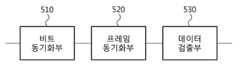
도 5는 도 4의 구성에서 Synchronizer(410)와 Data Detector(420)를 구체적으로 나타낸 블록도이다.
도 6은 도 5의 구성에서 프레임 동기화부(520)와 데이터 검출부(620)의 일 예를 구체적으로 나타낸 블록도이다.
도 7은 도 5의 구성에서 프레임 동기화부(520)와 데이터 검출부(620)의 다른일 예를 구체적으로 나타낸 블록도이다.
도 8은 일실시예에 따른 초저전력 초재생 수신 장치에서 복수개의 펄스-레벨 포지션들을 결정하는 일 예를 나타낸 도면이다.
도 9는 다른 일실시예에 따른 초저전력 초재생 수신 장치의 블록도이다.
도 10은 일실시예에 따른 초저전력 초재생 수신 장치에서 복수개의 펄스-레벨 포지션들을 결합(combining)하는 일 예를 나타낸 도면이다.
도 11은 일실시예에 따른 초저전력 초재생 수신 장치에서 샘플 타임 인덱스를 업데이트하고, 복수개의 펄스-레벨 포지션들을 결합하는 일 예를 나타낸 도면이다.
도 12는 다른 일실시예에 따른 초저전력 초재생 수신 장치의 블록도이다.
도 13은 일실시예에 따른 초저전력 초재생 수신 장치에서 복수개의 펄스-레벨 포지션들을 결정하는 방식들을 나타낸 도면이다.
도 14는 다른 일실시예에 따른 초저전력 초재생 수신 장치의 블록도이다.
도 15는 도 14의 구성에서 Bit sync.(1411), Frame sync.(1413) 및 Data Detector(1421)의 일 예를 구체적으로 나타낸 블록도이다.
도 16은 일실시예에 따른 초저전력 초재생 수신 장치에서 슬라이딩 윈도우를 이용하여 복수개의 펄스-레벨 포지션들을 결합하는 일 예를 나타낸 도면이다.
도 17은 다른 일실시예에 따른 초저전력 초재생 수신 장치의 블록도이다.
도 18은 일실시예에 따른 초저전력 초재생 수신 장치에서 슬라이딩 윈도우를 이용하여 비트 동기화를 수행하는 일 예를 나타낸 도면이다.
도 19는 일실시예에 따른 초저전력 초재생 수신 장치에서 샘플 타임 인덱스를 업데이트하고, 비트 동기화에 사용된 슬라이딩 윈도우를 이용하여 비트 시퀀스를 검출하는 일 예를 나타낸 도면이다.
도 20은 다른 일실시예에 따른 초저전력 초재생 수신 장치의 블록도이다.1 is a block diagram of a general super playback receiver.
2 is a graph illustrating an input signal, a damping function, and an output signal of a super-regulator oscillator.
FIG. 3 is a graph showing the product of the envelope, damping function, sensitivity curve and regenerative gain of the normalized input signal of the super regenerative oscillator and the envelope of the normalized output signal.
4 is a block diagram of an ultra low power ultra reproducing apparatus according to an embodiment.
FIG. 5 is a detailed block diagram illustrating the
FIG. 6 is a block diagram illustrating an example of the
FIG. 7 is a block diagram illustrating another example of the
8 is a diagram illustrating an example of determining a plurality of pulse-level positions in an ultra low power ultra reproducing receiving apparatus according to an embodiment.
9 is a block diagram of an ultra low power ultra reproducing apparatus according to another embodiment.
FIG. 10 is a diagram illustrating an example of combining a plurality of pulse-level positions in an ultra low power ultra reproducing receiving apparatus according to an embodiment.
FIG. 11 is a diagram illustrating an example of updating a sample time index and combining a plurality of pulse-level positions in an ultra low power ultra playback receiving apparatus according to an embodiment.
12 is a block diagram of an ultra low power ultra reproducing apparatus according to another exemplary embodiment.
FIG. 13 is a diagram illustrating a method of determining a plurality of pulse-level positions in an ultra low power ultra reproducing receiving apparatus according to an embodiment.
14 is a block diagram of an ultra low power ultra reproducing receiving apparatus according to another exemplary embodiment.
FIG. 15 is a block diagram illustrating an example of Bit sync. 1411, Frame sync. 1413, and Data Detector 1421 in the configuration of FIG. 14.
FIG. 16 is a diagram illustrating an example of combining a plurality of pulse-level positions using a sliding window in an ultra low power ultra reproducing receiving apparatus according to an embodiment.
17 is a block diagram of an ultra low power ultra reproducing apparatus according to another embodiment.
18 is a diagram illustrating an example of performing bit synchronization using a sliding window in an ultra-low power ultra-playback receiving apparatus according to an embodiment.
19 is a diagram illustrating an example of updating a sample time index and detecting a bit sequence by using a sliding window used for bit synchronization in an ultra low power ultra playback receiving apparatus according to an embodiment.
20 is a block diagram of an ultra low power ultra reproducing apparatus according to another embodiment.
이하, 일측에 따른 실시예를 첨부된 도면을 참조하여 상세하게 설명한다.Hereinafter, exemplary embodiments of the present invention will be described in detail with reference to the accompanying drawings.
무선 센서 네트워크 및 근거리 통신망에서 설치되는 다양한 센서 디바이스들은 소형, 저전력 및 저복잡도의 구조로 설계될 필요가 있다.Various sensor devices installed in wireless sensor networks and local area networks need to be designed in a compact, low power and low complexity structure.
기존의 super heterodyne RF 구조의 수신기는 수신 신호를 고주파 대역에서 바로 기저대역으로 변환하지 않고 중간주파수 대역을 활용하여 sensitivity 등의 성능을 향상시키지만, 이로 인해 복잡도, 비용, 전력소모 등이 증가한다.Conventional super heterodyne RF receivers do not convert the received signal from the high frequency band to the baseband, but use the intermediate frequency band to improve the performance such as sensitivity, but this increases the complexity, cost, and power consumption.
특히, super heterodyne RF 구조방식의 모뎀기술은 RF 부분에서 digital baseband 부분에 비해 매우 높은 전력을 요구한다. 예를 들어 저전력 WPAN을 위한 모뎀칩의 경우 디지털 신호처리 부분의 소모 전력은 송신, 수신 모두 0.5 mW 정도인 반면에, 아날로그 신호처리 부분의 소모전력은 수신모드에서 21mW, 송신모드에서 30mW 정도이다.In particular, the modem technology of the super heterodyne RF structure requires much higher power than the digital baseband part in the RF part. For example, in the case of a modem chip for low power WPAN, the power consumption of the digital signal processing portion is about 0.5 mW for both transmission and reception, while the power consumption of the analog signal processing portion is about 21 mW in the reception mode and about 30 mW in the transmission mode.
이러한 이유 때문에, 최근에는 다양한 저전력 RF 구조를 활용하여 전체 통신 모뎀의 저전력화 연구가 활발히 진행되고 있다. 특히, 초재생 수신기(super-regenerative receiver)를 활용한 수신기 구조는 수신 신호를 positive feedback 구조를 활용하여 출력신호를 증폭하여 신호를 검출하는 구조인데, 적은 수의 능동소자를 활용한 간단한 RF 구조여서, 초저전력 수신기로 주목받고 있다.For this reason, recently, studies on lowering power of an entire communication modem have been actively conducted using various low power RF structures. In particular, a receiver structure using a super-regenerative receiver detects a signal by amplifying an output signal by using a positive feedback structure, and is a simple RF structure using a small number of active devices. It is attracting attention as an ultra low power receiver.
이러한 저전력 및 저복잡도 RF 구조를 활용한 근거리 송수신 시스템은 비록 획기적인 전력감소를 가져오지만, 아날로그 신호처리 부분의 성능저하로 인해 전체적인 시스템의 성능저하를 초래하게 된다.Although a short-range transmission / reception system utilizing such a low power and low complexity RF structure brings a drastic power reduction, the performance degradation of the analog signal processing part causes the performance of the overall system.
초재생 수신기는 주파수 응답의 낮은 선택도(selectivity) 특성으로 인하여, 시스템의 성능열화가 심하게 나타난다.Super-regenerated receivers show severe performance degradation of the system due to the low selectivity of the frequency response.
도 1 일반적인 초재생 수신기의 블록도이다.1 is a block diagram of a typical super-play receiver.
도 1을 참조하면, LNA(Low Noise Amplifier)를 통과한 RF 신호는 Superregenerative oscillator(SRO)에 입력된다. SRO는 특정주파수의 RF 신호를 Ka(t)의 이득을 가지는 positive feedback 루프에 의해 증폭시킨다. 하지만 계속 증폭을 시키면 발진하게 되므로 발진을 다시 멈추게 하는 동작이 필요하다. Quench oscillator는 이러한 발진의 주기적인 생성과 소멸을 제어한다. SRO에 입력되는 RF 신호와 출력 신호 및 positive feedback 루프를 통한 closed-loop 시스템의 댐핑 함수는 도 2에서와 같이 표현될 수 있다.Referring to FIG. 1, an RF signal passing through a low noise amplifier (LNA) is input to a superregenerative oscillator (SRO). SRO amplifies an RF signal ata specific frequency by a positive feedback loop with a gain of Ka (t). However, if you continue to amplify the oscillation will be required to stop the oscillation again. Quench oscillators control the periodic generation and disappearance of these oscillations. The damping function of the closed-loop system through the RF signal and the output signal and the positive feedback loop input to the SRO can be expressed as shown in FIG.
Envelope detector는 SRO의 출력 신호에서 포락선을 검출하고, Lowpass filter는 검출된 포락선에서 소정의 영역을 필터링한다. 필터링 된 신호에 대해 비트 동기화, 프레임 동기화 및 데이터 검출이 이루어 질 수 있다.The envelope detector detects an envelope in the output signal of the SRO, and the lowpass filter filters a predetermined area in the detected envelope. Bit synchronization, frame synchronization, and data detection can be performed on the filtered signal.
도 2는 초재생 발진기의 입력 신호, 댐핑 함수(damping function) 및 출력 신호를 나타낸 그래프이다.2 is a graph illustrating an input signal, a damping function, and an output signal of a super-regulator oscillator.
도 2를 참조하면, SRO에 입력되는 RF 신호 v(t)에 대해 quench period Tq 마다 주기적인 발진과 감쇠가 반복되는 RF 펄스의 시리즈 형태로 SRO 출력 vo(t) 가 나타남을 알 수 있다.Referring to FIG. 2, it can be seen that the SRO output vo (t) appears as a series of RF pulses in which periodic oscillation and attenuation are repeated for each quench period Tq for the RF signal v (t) input to the SRO. .
여기서 ζ(t)는 closed-loop system 의 댐핑 함수에 해당하며 ζ(t)는 quench oscillator의 신호에 의해 달라진다. ζ(t)값이 양수에서 음수가 될 때 SRO 출력신호는 발진을 시작하며, amplitude 값이 서서히 증가하는 unstable 구간이 시작된다. unstable 구간은 ζ(t)값이 음수에서 다시 양수로 변화하는 순간까지 지속된다. amplitude값이 최대가 된 후 다시 감쇠하기 시작하는 stable 구간이 시작된다.Where ζ (t) corresponds to the damping function of the closed-loop system and ζ (t) depends on the signal of the quench oscillator. When the value of ζ (t) becomes positive from negative, the SRO output signal starts oscillating, and an unstable section begins to increase in amplitude. The unstable interval lasts until the moment ζ (t) changes from negative to positive. After the amplitude is maximized, the stable period begins to decay again.
참고로, 한번의 quench period동안 SRO 출력에서 발생한 RF pulse가 다음 번의 quench period에서도 다시 나타날 수 있는데 SRO 출력에서 발생한 RF pulse는 다음 번의 quench period에서 최초 생성되는 RF pulse와 중첩되어 ISI(intersymbol interference)를 발생시킬 수 있다. ISI가 발생하는 현상을 hangover 효과라고 부른다. ζ(t)은 hangover 효과를 제거하기 위해 dc component 값에 해당하는 ζdc 값을 가진다.For reference, the RF pulse generated at the SRO output during one quench period may reappear at the next quench period, and the RF pulse generated at the SRO output overlaps the RF pulse generated first at the next quench period to generate intersymbol interference (ISI). Can be generated. The phenomenon that ISI occurs is called hangover effect. ζ (t) has a ζdc value corresponding to the dc component value to eliminate the hangover effect.
SRO 출력 vo(t)의 amplitude값은 RF 입력 신호 v(t)의 amplitude 값이 클수록 커진다.The amplitude value of the SRO output vo (t) increases as the amplitude value of the RF input signal v (t) increases.
또한, vo(t)의 amplitude값의 크기를 결정하는 중요한 요인은 재생이득(regenerative gain) 이다. 재생이득은 민감도 곡선(sensitivity curve)과 SRO에 입력되는 RF 신호의 정규화된 포락선(normalized envelope)의 적분 값에 의해 결정된다.In addition, an important factor in determining the magnitude of the amplitude value of vo (t) is regenerative gain. The regenerative gain is determined by the sensitivity curve and the integral of the normalized envelope of the RF signal input to the SRO.
구체적인 수학식을 살펴보면 SRO의 RF 입력 신호


여기서 pc(t)는 최대값이 1로 정규화된 펄스 포락선을 의미한다. Kr는 재생이득, s(t)는 민감도 곡선, p(t)는 SRO 출력의 정규화된 포락선을 의미한다.Where pc (t) means the pulse envelope normalized to a maximum value of 1. Kr is the regenerative gain, s (t) is the sensitivity curve, and p (t) is the normalized envelope of the SRO output.
SRO 출력의 amplitude는 RF 입력 신호의 peak amplitude인 V 값뿐만 아니라, s(t)와 pc(t)의 적분 값에 따라 결정됨을 알 수 있다.It can be seen that the amplitude of the SRO output depends not only on the V value, which is the peak amplitude of the RF input signal, but also on the integral of s (t) and pc (t).
즉, SRO 출력의 peak amplitude는 단순히 RF 입력신호의 peak amplitude 값만 크다고 해서 증가하는 것이 아니고, s(t)가 얼마나 pc(t)와 겹쳐져서 입력 에너지를 잘 캡쳐 하는지에 따라 결정됨을 알 수 있다.That is, the peak amplitude of the SRO output does not increase simply because the peak amplitude value of the RF input signal is large, but is determined by how well s (t) overlaps with pc (t) to capture the input energy well. .
개념적으로 쉽게 이해하기 위해, 댐핑 함수 ζ(t)에 따른 pc(t), s(t), Krp(t) 신호 형태의 예를 그림으로 살펴보면 도 3과 같다.In order to understand the concept easily, examples of pc (t), s (t), and Kr p (t) signal types according to the damping function ζ (t) are illustrated in FIG. 3.
도 3은 초재생 발진기의 정규화된 입력 신호의 포락선, 댐핑 함수, 민감도 곡선(sensitivity curve) 및 재생이득(regenerative gain)과 정규화된 출력 신호의 포락선의 곱을 나타낸 그래프이다.FIG. 3 is a graph showing the product of the envelope, damping function, sensitivity curve and regenerative gain of the normalized input signal of the super regenerative oscillator and the envelope of the normalized output signal.
도 3을 참조하면, 민감도 곡선 s(t)는 댐핑 함수 ζ(t)값이 양수에서 음수로 변화하는 시간을 중심으로, 지수적으로 증가 후 다시 지수적으로 감소하는 형태를 가진다.Referring to FIG. 3, the sensitivity curve s (t) has a form in which the damping function ζ (t) changes exponentially and then decreases exponentially with respect to the time when the value of the damping function ζ (t) changes from positive to negative.
Krp(t)는 반대로 댐핑 함수 ζ(t) 값이 음수에서 양수로 변화하는 시간을 중심으로, 지수적으로 증가 후 다시 지수적으로 감소하는 형태를 가진다. 만약 도 3에서 s(t)와 Krp(t)신호가 거의 겹치지 않는다면 이 두 함수의 적분 값은 거의 0(zero)에 가깝게 될 것이고, SRO 출력 포락선의 amplitude 값 또한 거의 0(zero)에 가깝게 될 것이다.On the contrary, Kr p (t) has a form that decreases exponentially and then increases exponentially around the time when the damping function ζ (t) changes from negative to positive. If the s (t) and Kr p (t) signals in FIG. 3 hardly overlap, the integral of these two functions will be nearly zero, and the amplitude of the SRO output envelope will also be nearly zero. Will be close.
즉, s(t)는 SRO 입력 포락선의 에너지를 캡쳐해서 그 크기를 SRO 출력의 peak amplitude에 반영하는데, 여기서 s(t)의 시간 축 상의 위치보다 조금 지연된 시간에 SRO 출력 포락선이 나타난다.In other words, s (t) captures the energy of the SRO input envelope and reflects its magnitude in the peak amplitude of the SRO output, where the SRO output envelope appears at a slightly delayed time than the position on the time axis of s (t).
도 3에서 확인할 수 있는 것처럼, 초 저전력의 superregenerative RF 구조가 적용된 수신기는 기존의 고전력 및 고품위의 super-heterodyne RF 수신기에서의 특성과 다르게, 기저대역의 송신신호에 대한 정확한 형태를 획득하기가 어렵다는 문제가 있다.As can be seen in FIG. 3, a receiver having an ultra-low power superregenerative RF structure is difficult to obtain an accurate form of a baseband transmission signal unlike characteristics of a conventional high power and high quality super-heterodyne RF receiver. There is.
즉, SRO 출력은 RF 입력신호의 기저대역 신호를 복원하기 위해 주파수 변환과정을 거쳐 출력된 신호가 아니다.That is, the SRO output is not a signal output through a frequency conversion process to recover the baseband signal of the RF input signal.
SRO 출력은 특정 주파수의 RF 입력신호에 positive feedback으로 반응하여 발진된 전혀 다른 형태의 새롭게 생성된 신호이므로, SRO 출력은 송신신호의 포락선과는 무관한 형태를 가지게 된다.Since the SRO output is a newly generated signal that is oscillated in response to positive feedback of the RF input signal of a specific frequency, the SRO output has a form independent of the envelope of the transmission signal.
이러한 결과는 기존의 RF 수신기에서 통상적으로 사용하는 수신알고리즘을 적용하는데 있어 많은 제약을 가져온다. 따라서 통상적인 기존 수신알고리즘을 변경 적용하는 것이 필요하다.This result has many limitations in applying the reception algorithm commonly used in existing RF receivers. Therefore, it is necessary to change and apply a conventional reception algorithm.
s(t)는 시간에 따라 exponential 하게 변하는 특성 때문에, 댐핑 함수의 제로-크로싱 포인트(zero-crossing point)에 몰려있는 형태가 된다. 제로-크로싱 포인트는 양수에서 음수로 변화하는 지점을 의미한다.Since s (t) changes exponentially with time, it is concentrated in the zero-crossing point of the damping function. Zero-crossing point means a point that changes from positive to negative.
즉, 민감도 곡선 s(t)는 시간 축 상에서 RF 입력 신호의 포락선보다 훨씬 narrow한 특성을 갖게 된다. 그런데, s(t)의 narrow한 특성은 초재생 수신기의 선택도 특성을 열화시켜 결국 SNR(Signal-to-Noise Ratio) 값을 저하시킨다.In other words, the sensitivity curve s (t) is much narrower than the envelope of the RF input signal on the time axis. However, the narrow characteristic of s (t) deteriorates the selectivity characteristic of the super-reproducing receiver and eventually lowers the signal-to-noise ratio (SNR) value.
시간영역과 주파수영역에서의 변환에 대한 푸리에 트랜스폼 이론에 의하면 시간 축에서 wide한 신호는 주파수영역에서는 narrow한 특성을 가지며, 반대로 시간 축에서 narrow한 신호는 주파수영역에서 wide한 특성을 가지게 된다.According to the Fourier transform theory of the transform in the time domain and the frequency domain, a wide signal in the time domain has a narrow characteristic in the frequency domain, whereas a narrow signal in the time domain has a wide characteristic in the frequency domain.
따라서, 시간 영역에서 RF 입력 신호의 wide한 신호를 SRO에서 narrow한 특성의 s(t)로 수신하는 것은, 주파수 영역에서 살펴보면 RF 입력 신호의 narrow한 주파수 대역폭을 SRO의 wide한 주파수 대역폭으로 수신한 경우가 된다.Therefore, receiving the wide signal of the RF input signal in the SRO with a narrow characteristic s (t) in the SRO means receiving the narrow frequency bandwidth of the RF input signal in the SRO's wide frequency bandwidth. It is a case.
RF 입력 신호보다 더 넓은 주파수 영역에서 수신하게 되면, RF 입력 신호의 전력 대비 더 많은 additive white Gaussian noise (AWGN)의 전력이 수신되어 SNR 값이 열화된다.
When receiving in a wider frequency range than the RF input signal, more additive white Gaussian noise (AWGN) power is received compared to the power of the RF input signal, resulting in degradation of the SNR value.
도 4는 일실시예에 따른 초저전력 초재생 수신 장치의 블록도이다.4 is a block diagram of an ultra low power ultra reproducing apparatus according to an embodiment.
도 4를 참조하면, LNA(Low Noise Amplifier)를 통과한 RF 신호는 Superregenerative oscillator(SRO)에 입력된다. SRO는 특정주파수의 RF 신호를 Ka(t)의 이득을 가지는 positive feedback 루프에 의해 증폭시킨다. Quench oscillator는 이러한 발진의 주기적인 생성과 소멸을 제어한다. SRO의 출력 신호는 envelope detector 및 VGA(Voltage Gain Amplifier)를 통과할 수 있다.Referring to FIG. 4, an RF signal passing through a low noise amplifier (LNA) is input to a superregenerative oscillator (SRO). SRO amplifies an RF signal ata specific frequency by a positive feedback loop with a gain of Ka (t). Quench oscillators control the periodic generation and disappearance of these oscillations. The output signal from the SRO can pass through an envelope detector and a voltage gain amplifier (VGA).
ADC(Analog-Digital Converter)는 포락선의 피크값들에 대한 ADC sample값들을 샘플링할 수 있다. ADC sample값들은 Synchronizer(410)에서 동기를 맞추는 과정에 활용된다.The analog-to-digital converter (ADC) may sample ADC sample values for peak values of the envelope. The ADC sample values are used in the synchronization process in the
Synchronization 신호처리는 크게 비트단위의 시간 축에서 동기를 수행하는 비트 동기화와 비트 시퀀스 단위의 동기를 수행하는 프레임 동기화로 구별될 수 있다. 비트 시퀀스는 프레임의 시작을 나타낸다.Synchronization signal processing can be largely divided into bit synchronization performing synchronization on a time axis in units of bits and frame synchronization performing synchronization in units of bit sequences. The bit sequence indicates the beginning of the frame.
Frame sync.(413)는 Bit sync.(411)에서 획득한 비트 단위의 동기정보를 활용하여, 복수개의 비트들을 복조 함으로써, 비트 시퀀스를 검출할 수 있다.The frame sync. 413 may detect a bit sequence by demodulating a plurality of bits by utilizing the synchronization information of the bit unit obtained in the bit sync. 411.
Bit sync.(411)는 수신 심볼의 한 주기 내에서 가장 큰 크기의 ADC sample값을 찾아 시간 축에서 최적의 포지션을 추정한다.Bit sync. 411 estimates the optimal position on the time axis by finding the ADC sample value of the largest size in one period of the received symbol.
그런데, 만약 송신 심볼이 직접확산 스프레드 스펙트럼(DSSS, direct sequence spread spectrum)방식을 통해 변조되었다면, 수신 심볼의 주기는 한 칩(chip) 심볼의 주기에 해당하며, 한 비트의 주기는 한 칩 심볼의 주기에 확산 인자(spreading factor)를 곱한 값이 된다.However, if a transmission symbol is modulated by a direct sequence spread spectrum (DSSS) method, a period of a received symbol corresponds to a period of one chip symbol, and a period of one bit corresponds to a period of one chip symbol. The period is multiplied by the spreading factor.
여기서 확산 인자 값이 2 이상인 경우라면, 비트 동기화를 위해서는 한 수신 심볼의 주기 내에서 펄스-레벨 포지션(pulse-level position)를 추정하는 과정뿐 아니라, 한 비트주기 내에서 최적의 코드-레벨 포지션(code-level position)을 추정하는 과정이 필요하다.In this case, if the spreading factor value is 2 or more, not only the process of estimating the pulse-level position in the period of one received symbol but also the optimal code-level position in one bit period It is necessary to estimate the code-level position.
Bit sync.(411)는 서로 다른 펄스-레벨 포지션들에 대해, 가능한 모든 순환 이동(circularly shifted)된 코드 시퀀스 간에 상관(correlation) 값을 계산하여, 가장 큰 크기의 상관 값을 획득하고, 가장 큰 상관 값을 갖는 경우의 펄스-레벨 포지션 및 코드-레벨 포지션을 추정할 수 있다.Bit sync. 411 calculates the correlation value between all possible circularly shifted code sequences for different pulse-level positions, obtaining the largest correlation value, It is possible to estimate the pulse-level position and the code-level position when having a correlation value.
Frame sync.(413)와 Data Detector(420)는 펄스-레벨 신호 결합방식을 이용할 수 있다. 펄스-레벨 신호 결합방식은 Bit sync.(411)에서 추정된 펄스-레벨 포지션에 기초하여 복수개의 펄스-레벨 포지션들을 결정하고, 결정된 펄스-레벨 포지션들을 결합하는 방식을 의미한다. 초저전력 초재생 수신 장치는 복수개의 펄스-레벨 포지션을 결합하여 프레임 동기화 및 데이터 검출을 수행함으로써, 수신 신호의 SNR을 증가할 수 있다.The frame sync. 413 and the
도 5는 도 4의 구성에서 Synchronizer(410)와 Data Detector(420)를 구체적으로 나타낸 블록도이다. Synchronizer(410)는 Bit sync.(411) 및 Frame sync.(413)를 포함하는데, 도 5를 참조하면, Bit sync.(411)는 비트 동기화부(510)에 대응하고, Frame sync.(413)는 프레임 동기화부(520)에 대응한다. Data Detector(420)는 데이터 검출부(530)에 대응한다.FIG. 5 is a detailed block diagram illustrating the
비트 동기화부(510)는 초재생 발진기에서 출력된 신호에서 샘플링 된 값을 이용하여 수신 심볼의 한 주기 내에서 최대 진폭 값을 가지는 펄스-레벨 포지션을 추정할 수 있다. 이때, 샘플링 된 값은 ADC 샘플링 된 값을 의미한다. 비트 동기화부(510)는 추정된 펄스-레벨 포지션을 이용하여 송신 심볼의 비트와 수신 심볼의 비트를 동기화 할 수 있다.The
비트 동기화부(510)는 수신 심볼의 한 주기 내에서 최대 상관 값을 가지는 경우의 펄스-레벨 포지션 및 코드-레벨 포지션을 추정할 수 있다. 이때의 수신 심볼은 직접확산 스프레드 스펙트럼(DSSS, direct sequence spread spectrum)방식을 통해 변조된 경우이다. 즉, 한 칩 심볼의 주기에 확산 인자 값이 2이상인 경우이다.The
프레임 동기화부(520)는 비트 동기화부(510)에서 추정된 펄스-레벨 포지션에 기초하여 결합(combining)할 복수개의 펄스-레벨 포지션들을 결정한다. 프레임 동기화부(520)는 결정된 복수개의 펄스-레벨 포지션들을 결합(combining)한다.The
프레임 동기화부(520)는 결합된 복수개의 펄스-레벨 포지션들을 이용하여 소정의 비트 시퀀스를 검출함으로써 프레임 동기화를 수행할 수 있다. 이때, 소정의 비트 시퀀스는 프레임의 시작을 나타낸다.The
데이터 검출부(530)는 프레임 동기화 완료 후, 프레임 동기화부(520)에서 결정된 복수개의 펄스-레벨 포지션들을 이용하여 데이터를 검출한다. 프레임 동기화가 완료되면, 이후의 수신 심볼에서 샘플링 되는 샘플 값들은 데이터를 의미한다.After the frame synchronization is completed, the
데이터 검출부(530)는 샘플 값들 중에서 프레임 동기화부(520)에서 결정된 복수개의 펄스-레벨 포지션에 대응하는 샘플 값들을 선택하고, 결합함으로써, 데이터를 검출할 수 있다.
The
도 6은 도 5의 구성에서 프레임 동기화부(520)와 데이터 검출부(530)의 일 예를 구체적으로 나타낸 블록도이다.FIG. 6 is a block diagram illustrating an example of the
도 6을 참조하면, 프레임 동기화부(520)는 프레임 동기화부(610)에 대응하고, 데이터 검출부(530)는 데이터 검출부(620)에 대응한다.Referring to FIG. 6, the
프레임 동기화부(610)는 결합대상 결정부(611), 제1 결합부(612), 신호전력 추정부(613), 업데이트부(614), 제1 선택부(615), 제2 결합부(616) 및 비트 시퀀스 검출부(617)를 포함할 수 있다.The
결합대상 결정부(611)는 비트 동기화 단계에서 추정된 펄스-레벨 포지션에 기초하여 결합의 대상이 되는 서로 다른 복수개의 펄스-레벨 포지션들을 결정할 수 있다.The combining
결합대상 결정부(611)는 수신 심볼의 한 주기 내에서 비트 동기화 단계에서 추정된 펄스-레벨 포지션을 중심으로 양쪽으로 서로 동일한 개수의 펄스-레벨 포지션들을 결정할 수 있다. 여기서 수신 심볼의 한 주기는 한 칩 심볼의 주기를 의미한다.The combining
결합대상 결정부(611)는 수신 심볼의 한 주기 내에서 비트 동기화 단계에서 추정된 펄스-레벨 포지션과 인접한 펄스-레벨 포지션들의 상관 값을 계산하고, 상관 값의 크기 순서로 복수개의 펄스-레벨 포지션들을 결합의 대상으로 결정할 수 있다.The combining
결합대상 결정부(611)는 수신 심볼의 한 주기 내에서 비트 동기화 단계에서 추정된 펄스-레벨 포지션과 인접한 펄스-레벨 포지션들의 상관 값을 계산하고, 상관 값의 크기가 소정의 임계 값보다 큰 경우에 해당하는 펄스-레벨 포지션들을 결합의 대상으로 결정할 수 있다. 상관 값이 매우 낮은 펄스-레벨 포지션이 필요 없이 결합되는 경우가 배제될 수 있다.The combining
제1 결합부(612)는 동일한 비트 주기에서 결합대상 결정부(611)에서 결정된 복수개의 펄스-레벨 포지션들을 결합할 수 있다. 동일한 비트 주기라 함은 하나의 비트 심볼을 나타내는 주기를 의미한다. 제1 결합부(612)는 칩 단위마다 복수개의 펄스-레벨 포지션들을 결합할 수 있다. 제1 결합부(612)는 각각의 펄스-레벨 포지션들에 동일한 가중치를 적용하여 결합할 수 있다. 이런 결합 방식을 동일 이득 결합 방식이라고 정의할 수 있다.The
신호전력 추정부(613)는 제1 결합부(612)의 결합으로 생성된 신호의 신호전력(signal power)을 추정할 수 있다. 신호전력 추정부(613)는 칩 단위마다 결합된 복수개의 펄스-레벨 포지션들의 신호전력을 추정할 수 있다. 즉, 동일한 비트 주기에서 확산 인자의 수만큼 신호전력들이 추정될 수 있다. 이때, 추정되는 신호전력에 기초하여 추후 비트 시퀀스 검출 및 데이터 검출의 기준이 결정될 수 있다.The
업데이트부(614)는 비트 동기화 단계에서 추정된 펄스-레벨 포지션의 인덱스, 추정된 코드-레벨 포지션의 인덱스 및 결합대상 결정부(611)에서 결정된 복수개의 펄스-레벨 포지션들에 기초하여 비트 동기화 단계에서 샘플링 된 샘플의 샘플 타임 인덱스를 업데이트할 수 있다. 샘플 타임 인덱스는 샘플링 된 샘플들의 시간축 상에서의 인덱스를 의미한다. 프레임 동기화 과정에서 동일한 비트 주기에 대해 결정된 샘플들을 결합하기 위해 샘플 타임 인덱스가 업데이트 될 수 있다.The
제1 선택부(615)는 업데이트 된 샘플 타임 인덱스에 기초하여 결합대상 결정부(611)에서 결정된 복수개의 펄스-레벨 포지션들을 선택할 수 있다. 제1 선택부(615)는 비트 동기화 과정에서 사용된 샘플들 이후에 샘플링 된 샘플들에 대해서 결합대상 결정부(611)에서 결정된 복수개의 펄스-레벨 포지션들을 선택할 수 있다.The
제2 결합부(616)는 제1 선택부(615)에서 선택된 복수개의 펄스-레벨 포지션들을 결합할 수 있다. 제2 결합부(616)는 동일 이득 결합 방식을 이용하여 결합을 수행할 수 있다.The
비트 시퀀스 검출부(617)는 제2 결합부(616)에서 결합하여 생성된 신호와 신호전력 추정부(613)에서 추정된 신호전력에 기초하여 소정의 비트 시퀀스를 검출할 수 있다. 신호전력 추정부(613)에서 추정된 신호전력은 검출된 비트 값이 0또는 1인지 판단하는 기준이 될 수 있다.The
예를 들면, 비트 시퀀스 검출부(617)는 제2 결합부(616)에서 결합하여 생성된 신호가 신호전력 추정부(613)에서 추정된 신호전력보다 큰 값을 가지면, 1이 수신되었다고 판단할 수 있고, 작은 값을 가지면 0이 수신되었다고 판단할 수 있다. 송신단과 수신단 간에 약속된 비트 시퀀스가 비트 시퀀스 검출부(617)에서 검출되면, 비트 시퀀스 검출부(617)는 프레임이 동기화되었다고 판단할 수 있다.For example, the
데이터 검출부(620)는 제2 선택부(621), 제3 결합부(622) 및 복조부(623)를 포함할 수 있다.The
제2 선택부(621)는 비트 시퀀스 검출부(617)에서 소정의 비트 시퀀스가 검출된 후, 업데이트 된 샘플 타임 인덱스에 기초하여 결합대상 결정부(611)에서 결정된 복수개의 펄스-레벨 포지션들을 선택할 수 있다.After the predetermined sequence of bits is detected by the
제2 선택부(621)는 프레임 동기화 과정에서 사용된 샘플들 이후에 샘플링 된 샘플들에 대해서 결합대상 결정부(611)에서 결정된 복수개의 펄스-레벨 포지션들과 매칭되는 샘플들을 선택할 수 있다.The
제3 결합부(622)는 제2 선택부(621)에서 선택된 복수개의 펄스-레벨 포지션들을 결합할 수 있다. 제3 결합부(622)는 동일 이득 결합 방식을 이용하여 결합을 수행할 수 있다.The
복조부(623)는 제3 결합부(622)에서 결합하여 생성된 신호와 신호전력 추정부(613)에서 추정된 신호전력에 기초하여 데이터를 복조할 수 있다.The
복조부(623)는 제3 결합부(622)에서 결합하여 생성된 신호가 신호전력 추정부(613)에서 추정된 신호전력보다 크면, 수신된 심볼을 1로 판단하고, 그 반대의 경우에는 수신된 심볼을 0으로 판단할 수 있다.
The
도 7은 도 5의 구성에서 프레임 동기화부(520)와 데이터 검출부(530)의 다른일 예를 구체적으로 나타낸 블록도이다.FIG. 7 is a block diagram illustrating another example of the
도 7을 참조하면, 프레임 동기화부(520)는 프레임 동기화부(710)에 대응하고, 데이터 검출부(530)는 데이터 검출부(720)에 대응한다.Referring to FIG. 7, the
프레임 동기화부(710)는 결합대상 결정부(711), 신호전력 추정부(712), 업데이트부(713), 제1 선택부(714), 제1 결합부(715) 및 비트 시퀀스 검출부(716)를 포함할 수 있다.The
결합대상 결정부(711)는 비트 동기화 단계에서 추정된 펄스-레벨 포지션에 기초하여 결합의 대상이 되는 복수개의 펄스-레벨 포지션들을 결정할 수 있다.The combining
신호전력 추정부(712)는 결합대상 결정부(711)에서 결정된 복수개의 펄스-레벨 포지션들 각각의 신호전력(signal power)을 추정할 수 있다.The
업데이트부(713)는 비트 동기화 단계에서 추정된 펄스-레벨 포지션의 인덱스, 추정된 코드-레벨 포지션의 인덱스 및 결합대상 결정부(711)에서 결정된 복수개의 펄스-레벨 포지션들에 기초하여 비트 동기화 단계에서 샘플링 된 샘플의 샘플 타임 인덱스를 업데이트할 수 있다.The
제1 선택부(714)는 업데이트 된 샘플 타임 인덱스에 기초하여 결합대상 결정부(711)에서 결정된 복수개의 펄스-레벨 포지션들을 선택할 수 있다. 제1 선택부(714)는 비트 동기화 과정에서 사용된 샘플들 이후에 샘플링 된 샘플들에 대해서 결합대상 결정부(711)에서 결정된 복수개의 펄스-레벨 포지션들을 선택할 수 있다.The
제1 결합부(715)는 제1 선택부(714)에서 선택된 복수개의 펄스-레벨 포지션들을 선형 결합(linear combining) 또는 비선형 결합(nonlinear combining) 할 수 있다. 제1 결합부(715)는 선택된 복수개의 펄스-레벨 포지션들 각각의 신호전력을 고려하여 선형 결합 또는 비선형 결합을 결정할 수 있다. 또는, 제1 결합부(715)는 선택된 복수개의 펄스-레벨 포지션들 각각의 신호전력을 고려하여 각각의 펄스-레벨 포지션에 적용되는 가중치를 결정할 수도 있다. 이때, 각각의 신호전력은 신호전력 추정부(712)에서 추정될 수 있다.The
비트 시퀀스 검출부(716)는 제1 결합부(715)에서 결합하여 생성된 신호와 신호전력 추정부(712)에서 추정된 신호전력에 기초하여 소정의 비트 시퀀스를 검출할 수 있다. 신호전력 추정부(712)에서 추정된 신호전력은 검출된 비트 값이 0또는 1인지 판단하는 기준이 될 수 있다. 송신단과 수신단 간에 약속된 비트 시퀀스가 비트 시퀀스 검출부(716)에서 검출되면, 비트 시퀀스 검출부(716)는 프레임이 동기화되었다고 판단할 수 있다.The
데이터 검출부(720)는 제2 선택부(721), 제2 결합부(722) 및 복조부(723)를 포함할 수 있다.The
제2 선택부(721)는 비트 시퀀스 검출부(716)에서 소정의 비트 시퀀스가 검출된 후, 업데이트 된 샘플 타임 인덱스에 기초하여 결합대상 결정부(711)에서 결정된 복수개의 펄스-레벨 포지션들을 선택할 수 있다.After the predetermined bit sequence is detected by the
제2 결합부(722)는 제2 선택부(721)에서 선택된 복수개의 펄스-레벨 포지션들을 제1 결합부(715)에서 결합된 방식으로 결합할 수 있다. 제1 결합부(715)에서 선형 결합을 이용하였다면, 제2 결합부(722)도 선형 결합을 이용할 수 있다.The
복조부(723)는 제2 결합부(722)에서 결합하여 생성된 신호와 신호전력 추정부(712)에서 추정된 신호전력에 기초하여 데이터를 복조할 수 있다.
The
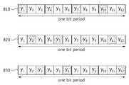
도 8은 일실시예에 따른 초저전력 초재생 수신 장치에서 복수개의 펄스-레벨 포지션들을 결정하는 일 예를 나타낸 도면이다.8 is a diagram illustrating an example of determining a plurality of pulse-level positions in an ultra low power ultra reproducing receiving apparatus according to an embodiment.
초저전력 초재생 수신 장치는 최대 상관 값을 가지는 펄스-레벨 포지션의 주변 펄스-레벨 포지션의 상관 값을 계산하여 결합의 대상이 되는 펄스-레벨 포지션을 결정할 수 있다.The ultra low power super reproduction reception apparatus may determine a pulse-level position to be combined by calculating a correlation value of a peripheral pulse-level position of a pulse-level position having a maximum correlation value.
한 칩(chip) 심볼당 M개의 ADC 샘플 값이 샘플링 되고, DSSS방식이 적용되어 확산 인자 값이 L 이라고 가정하면, 한 비트의 심볼 주기 내에서 ML개의 ADC 샘플 값들이 얻어진다.Assuming that M ADC sample values are sampled per chip symbol, and the DSSS method is applied and the spreading factor value is L, ML ADC sample values are obtained within one bit symbol period.
예를 들면, M=3, L=4 인 경우 비트 동기화 단계에서 한 비트의 심볼 주기 동안 시간순서대로 y1, y2,…, y12의 ADC 샘플들을 획득하였다고 가정한다.For example, in the case of M = 3, L = 4, y1 , y2 ,... , assume that ADC samples of y12 were obtained.
이때, 송신단의 코드 시퀀스(code sequence) C=[c1, c2, c3, c4] 라고 했을 때, 수신단에서 최대의 상관 값을 갖는 경우가 [y1, y4, y7, y10]·[c4, c1, c2, c3]T, [y2, y5, y8, y11]·[c4, c1, c2, c3]T, [y3, y6, y9, y12]·[c4, c1, c2, c3]T 인 3가지 경우를 가정할 수 있다.In this case, when the code sequence C = [c1 , c2 , c3 , c4 ] of the transmitting end has a maximum correlation value at the receiving end, [y1 , y4 , y7 , y10 ] · [c4 , c1 , c2 , c3 ]T , [y2 , y5 , y8 , y11 ] · [c4 , c1 , c2 , c3 ]T , [y3, y 6, y 9, y 12] · [
도 8은 위의 3가지 경우를 나타낸다. 도 8은 [y1, y4, y7, y10]·[c4, c1, c2, c3]T 에 대응하는 경우(810), [y2, y5, y8, y11]·[c4, c1, c2, c3]T 에 대응하는 경우(820), [y3, y6, y9, y12]·[c4, c1, c2, c3]T 에 대응하는 경우(830)를 나타낸다. 여기서 [·]T는 벡터에 대한 트랜스포즈(transpose)를 나타낸다.8 illustrates the above three cases. 8 corresponds to [y1 , y4 , y7 , y10 ] · [c4 , c1 , c2 , c3 ]T (810), [y2 , y5 , y8 , y11 ] · [c4 , c1 , c2 , c3 ] whenT (820), [y3 , y6 , y9 , y12 ] · [c4 , c1 , c2 , c3 ] corresponds toT (830). Where [·]T represents the transpose of the vector.
흰색이 아닌 색으로 표시된 ADC 샘플 들은, 코드 시퀀스가 두 번째 칩 심볼 포지션에서 시작 될 때(즉, 순환 이동(circularly shifted)된 코드 시퀀스 = [c4, c1, c2, c3]일 때) 각각 첫 번째, 두 번째, 세 번째의 펄스-레벨 포지션 에서 최대의 상관 값을 갖는 경우를 나타낸다.ADC samples marked with a color other than white are used when the code sequence starts at the second chip symbol position (ie, when the circularly shifted code sequence = [c4 , c1 , c2 , c3 ]). ) Shows the maximum correlation values at the first, second and third pulse-level positions, respectively.
첫 번째 경우(810)에서 만약 최대의 상관 값을 갖는 펄스-레벨 포지션의 왼쪽 펄스-레벨 포지션에서 상관 값을 계산하고 싶다면, ADC 샘플 값들은 [y3, y6, y9, y12]을 선택하면 되고, 순환 이동(circularly shifted)된 코드 시퀀스 [c1, c2, c3, c4]를 선택하여 상관 값 [y3, y6, y9, y12]· [c1, c2, c3, c4]T을 계산하면 된다.In the first case (810), if we want to calculate the correlation at the left pulse-level position of the pulse-level position with the highest correlation value, the ADC sample values are [y3 , y6 , y9 , y12 ]. Select the code sequence [c1 , c2 , c3 , c4 ] that is circularly shifted, and select the correlation value [y3 , y6 , y9 , y12 ] · [c1 , c2 , c3 , c4 ]T can be calculated.
여기서 주의할 점은 처음, 최대 상관 값을 가지는 경우에 [y1, y4, y7, y10]에 곱해지는 순환 이동(circularly shifted)된 코드 시퀀스는 [c4, c1, c2, c3]이었으나 [y3, y6, y9, y12]에 대해 상관 값을 계산하기 위해서 곱해지는 순환 이동(circularly shifted)된 코드 시퀀스는 왼쪽으로 한번 순환(shift)된 [c1, c2, c3, c4]라는 점이다.Note that the circularly shifted code sequence multiplied by [y1 , y4 , y7 , y10 ] when the maximum correlation value is first obtained is [c4 , c1 , c2 , c3 ] but a circularly shifted code sequence that is multiplied to calculate the correlation for [y3 , y6 , y9 , y12 ] is shifted once to the left [c1 , c2 , c3 , c4 ].
최대 상관 값을 가지는 펄스-레벨 포지션에 인접한 펄스-레벨 포지션을 결합하기 위해서는 같은 칩 심볼 주기 안에 속해야 한다. 따라서, y3와 y4가 같은 칩 심볼 주기에 속하기 위해서는 코드 시퀀스가 왼쪽으로 한번 순환되어야 함을 알 수 있다.In order to combine the pulse-level position adjacent to the pulse-level position with the maximum correlation value, it must be within the same chip symbol period. Thus, in order for y3 and y4 to belong to the same chip symbol period, the code sequence has to be cycled once to the left.
두 번째 경우(820)에서 만약 최대의 상관 값을 갖는 펄스-레벨 포지션의 왼쪽 펄스-레벨 포지션에서 상관 값을 계산하고 싶다면, ADC 샘플 값들은 [y1, y4, y7, y10]을 선택하면 되고, 순환 이동(circularly shifted)된 코드 시퀀스는 최대 상관 값을 가지는 코드 시퀀스 [c4, c1, c2, c3]를 선택하면 된다.In the second case (820), if we want to calculate the correlation at the left pulse-level position of the pulse-level position with the highest correlation value, the ADC sample values are [y1 , y4 , y7 , y10 ]. The code sequence that is circularly shifted may be selected by selecting the code sequence [c4 , c1 , c2 , c3 ] having the maximum correlation value.
세 번째 경우(830)에서 만약 최대의 상관 값을 갖는 펄스-레벨 포지션의 오른쪽 펄스-레벨 포지션에서 상관 값을 계산하고 싶다면, ADC 샘플 값들은 [y1, y4, y7, y10]을 선택하면 되고, 순환 이동(circularly shifted)된 코드 시퀀스는 최대 상관 값을 가지는 코드 시퀀스 [c4, c1, c2, c3]에서 오른쪽으로 한번 순환된 [c3, c4, c1, c2] 를 선택하면 된다.In the third case (830), if we want to calculate the correlation value at the right pulse-level position of the pulse-level position with the maximum correlation value, the ADC sample values are [y1 , y4 , y7 , y10 ]. A circularly shifted code sequence can be selected by circulating the code sequence [c4 , c1 , c2 , c3 ] having the maximum correlation value once to the right [c3 , c4 , c1 , c2 ].
또한 상관 값들은 최대의 상관 값을 계산하기 위해 메모리에 저장된 비트 동기화 단계에서 계산하였던 값들을 활용 할 수 있다.In addition, the correlation values may utilize the values calculated in the bit synchronization step stored in memory to calculate the maximum correlation value.
최대 상관 값을 가지는 펄스-레벨 포지션에 인접한 펄스-레벨 포지션의 상관 값을 계산하는 방식을 일반화시켜 수식적으로 나타낸다면 다음과 같다.A generalized method of calculating the correlation value of the pulse-level position adjacent to the pulse-level position having the maximum correlation value is expressed as follows.
비트 동기화 단계에서 추정된 최대 상관 값을 가지는 경우의 펄스-레벨 포지션 m* 및 코드-레벨 포지션 l* 는 다음과 같이 계산될 수 있다.The pulse-level position m* and the code-level position l* when having the maximum correlation value estimated in the bit synchronization step may be calculated as follows.

m*에 오른쪽으로 i만큼 인접한 펄스-레벨 포지션에 대한 인덱스는


fX(x)는 x를 연산자로 하는 모듈로 연산을 의미한다. X는 양의 정수이다.fX (x) means modulo operation with x as the operator. X is a positive integer.
결합의 대상이 되는 펄스-레벨 포지션의 인덱스들은 동일한 칩 심볼 주기 안에 포함되어야 하므로,

상관 값은 복수개의 비트 심볼 구간에서 반복적으로 계산될 수 있으며 이때, 상관 값은 해당 비트 수에 대한 평균값이 사용될 수 있다.
The correlation value may be repeatedly calculated in a plurality of bit symbol intervals, and the correlation value may be an average value for the corresponding number of bits.
도 9는 다른 일실시예에 따른 초저전력 초재생 수신 장치의 블록도이다.9 is a block diagram of an ultra low power ultra reproducing apparatus according to another embodiment.
Bit synchronization(910)에서 최대 상관 값을 가지는 펄스-레벨 포지션 및 코드-레벨 포지션이 추정되면, Frame synchronization(920)은 펄스-레벨 신호 결합(Pulse-level signal combining)(921)을 수행한다.When the pulse-level position and the code-level position having the maximum correlation value are estimated in the
펄스-레벨 신호 결합(921)은 펄스-레벨 포지션의 선택(pulse-level position selection)(922) 및 모듈로 동일 이득 결합(Modulo equal gain combining)(923)을 통해 이루어질 수 있다. 모듈로 동일 이득 결합(Modulo equal gain combining)(923)이란 동일한 비트 주기에서 샘플들을 결합하기 위해, 하나의 비트 주기를 넘어가는 샘플들에 대해서는 동일한 비트 주기의 샘플로 바꾸어주어 결합을 수행하는 것을 의미한다.Pulse-level signal combining 921 may be achieved through pulse-
Frame synchronization(920)은 결합된 신호에 대해 신호 전력을 추정(924)하고, 샘플 타임 인덱스를 업데이트(925)한다. 업데이트 된 샘플 타임 인덱스에 기초하여 Frame synchronization(920)은 펄스-레벨 신호 결합(926)을 수행할 수 있다. Frame synchronization(920)은 펄스-레벨 포지션의 선택(pulse-level position selection)(922)을 통해 선택된 펄스-레벨 포지션들에 매칭되는 샘플들을 ADC 샘플들 중에서 선택한다. 이는 펄스-레벨 포지션 선택(pulse-level position selection)(927)을 통해 이루어질 수 있다. Frame synchronization(920)은 선택된 샘플들을 동일 이득 결합 방식으로 결합(928)하고, 결합된 샘플들에 기초하여 SFD(Start Frame Delimiter)를 검출(929)한다.
도 10은 일실시예에 따른 초저전력 초재생 수신 장치에서 복수개의 펄스-레벨 포지션들을 결합(combining)하는 일 예를 나타낸 도면이다.FIG. 10 is a diagram illustrating an example of combining a plurality of pulse-level positions in an ultra low power ultra reproducing receiving apparatus according to an embodiment.
보다 구체적으로 도 10은 모듈로 동일 이득 결합(Modulo equal gain combining)의 예를 나타낸다.More specifically, FIG. 10 shows an example of modulo equal gain combining.
도 10은 칩 당 샘플 수 M=3, 확산 인자 L=4이고, 비트 동기화 단계에서 추정된 펄스-레벨 포지션이 첫 번째 포지션이고, 추정된 펄스-레벨 포지션의 왼쪽에 인접한 포지션이 결합대상으로 결정되어 위 두 포지션들을 모듈로 동일 이득 결합하는 경우를 나타낸다.10 shows that the number of samples per chip M = 3, the spreading factor L = 4, the pulse-level position estimated in the bit synchronization step is the first position, and the position adjacent to the left of the estimated pulse-level position is determined to be the target of coupling. In this case, the above two positions are equally coupled to the module.
비트 동기화 단계에서 추정된 펄스-레벨 포지션의 인덱스는 m*=1로 표현되고, 추정된 펄스-레벨 포지션의 왼쪽에 인접한 펄스-레벨 포지션의 인덱스는
하나의 비트에 대해 4개의 칩이 형성되므로, 4개의 결합신호가 생성될 수 있다. 4개의 결합신호에는 y1과 y12의 결합(1010)신호, y4과 y3의 결합(1020)신호, y7과 y6의 결합(1030)신호, y10과 y9의 결합(1040)신호가 포함된다.Since four chips are formed for one bit, four combined signals may be generated. The four combined signals include a combined 1010 signal of y1 and y12 , a combined 1020 signal of y4 and y3 , a combined 1030 signal of y7 and y6 , and a combination of y10 and y9 (1040). ) Signal is included.
모듈로 동일 이득 결합을 일반화시켜 수식적으로 나타낸다면 다음과 다음과 같이 표현될 수 있다.If the modulo equal gain coupling is generalized and expressed mathematically, it can be expressed as follows.

펄스-레벨 선택(Pulse-level position selection)과정에서 선택된 인덱스 세트를 S라고 했을 때, 시간 순서상으로 j번째 모듈로 동일 이득 결합의 출력 값은 zj로 표현될 수 있다.When the index set selected in the pulse-level position selection process is S, the output value of the same gain coupling to the jth module in time order may be expressed as zj .
S는 비트 동기화 단계에서 추정된 펄스-레벨 포지션의 인덱스 m*(1≤ m*≤M)을 포함하며 S의 각 원소들은 m*에 오른쪽으로 i만큼 인접한 펄스-레벨 포지션에 대한 인덱스가 선택된 경우, m*+i로 표시하고 왼쪽으로 i만큼 인접한 펄스-레벨 포지션에 대한 인덱스가 선택된 경우 m*-i라고 표시된다.S contains the index m* (1≤m* ≤M) of the pulse-level position estimated in the bit-synchronization step, and each element of S is selected with an index for the pulse-level position adjacent to m* by i to the right. , m* + i and m* -i if the index for the pulse-level position adjacent to i is selected to the left.
모듈로 동일 이득 결합의 신호처리가 수행된 후, 결합 신호에 대해 신호전력이 추정될 수 있다.
After signal processing of the same gain coupling is modulated, signal power may be estimated for the combined signal.
도 11은 일실시예에 따른 초저전력 초재생 수신 장치에서 샘플 타임 인덱스를 업데이트하고, 복수개의 펄스-레벨 포지션들을 결합하는 일 예를 나타낸 도면이다.FIG. 11 is a diagram illustrating an example of updating a sample time index and combining a plurality of pulse-level positions in an ultra low power ultra playback receiving apparatus according to an embodiment.
샘플링 된 샘플의 샘플 타임 인덱스는 비트 동기화 과정에서 추정된 펄스-레벨 포지션의 인덱스, 추정된 코드-레벨 포지션의 인덱스 및 선택된 복수개의 펄스-레벨 포지션들에 기초하여 업데이트될 수 있다.The sample time index of the sampled sample may be updated based on the index of the estimated pulse-level position, the index of the estimated code-level position, and the selected plurality of pulse-level positions in the bit synchronization process.
초저전력 초재생 수신 장치는 샘플 타임 인덱스의 업데이트 후, 펄스-레벨 신호 결합의 신호처리 과정을 다시 수행한다.After the update of the sample time index, the ultra low power super reproduction receiving apparatus performs signal processing of pulse-level signal combining again.
도 11은 M=3, L=4 인 경우에 샘플 타임 인덱스의 업데이트(1130) 및 펄스-레벨 신호 결합의 신호처리 과정(1140, 1150, 1160, 1170)을 나타낸다.11 illustrates the
첫 번째 비트 심볼 주기(1110) 동안에는 비트 동기화가 수행되며 첫 번째 비트 심볼 주기(1110)의 ADC 샘플들을 이용하여 펄스-레벨 포지션 선택(pulse-level position selection), 모듈로 동일 이득 결합(modulo equal gain combining) 및 신호전력 추정(signal power estimation)의 신호처리가 수행될 수 있다.Bit synchronization is performed during the first
비트 동기화 과정에서 추정된 펄스-레벨 포지션의 인덱스, 추정된 코드-레벨 포지션의 인덱스가 각각 m*=1,
첫 번째 비트 심볼 주기(1110)의 그 다음 2개의 ADC 샘플 값들은 버리고 다음에 이어지는 ADC 샘플 값부터 프레임 동기화에 활용될 수 있다. 2개의 ADC 샘플 값들은 주어진 코드 시퀀스에서의 첫 번째 칩 심볼에 해당하는 값이 아니기 때문이다.The next two ADC sample values of the first
두 번째 비트 심볼 주기(1120)에서 프레임 동기화를 위해 첫 번째 ADC 샘플 y'1과 두 번째 ADC 샘플 y'2간에 결합(1140)이 이루어지고, 칩 단위별로 동일한 위치에서 결합들(1150, 1160, 1170)이 이루어질 수 있다.In the second
샘플 타임 인덱스 업데이트 방법을 일반적인 경우에 대해 수식적으로 표현하면 다음과 같다.The sample time index update method is expressed as follows for the general case.
펄스-레벨 포지션 선택 과정에서 선택된 인덱스 세트를 S라고 하면, S의 원소 중 가장 작은 인덱스를 가지는 원소를 mmin라고 표현할 수 있다.If the index set selected in the pulse-level position selection process is S, an element having the smallest index among the elements of S may be expressed as mmin .
프레임 동기화에 사용되는 첫 번째 샘플 타임 인덱스는 비트 동기화에 사용되는 마지막 샘플 타임 인덱스로부터

이후의 펄스-레벨 포지션의 결합은 다음과 같이 수행될 수 있다. 초저전력 초재생 수신 장치는 인덱스 세트 S의 각 원소에서 mmin을 뺀 새로운 원소들로 구성된 인덱스 세트 S'를 계산한다.The subsequent combination of pulse-level positions may be performed as follows. The ultra low power super reproduction receiving apparatus calculates an index set S 'composed of new elements minus mmin from each element of the index set S.
첫 번째 펄스-레벨 포지션의 결합은 업데이트 된 샘플 타임 인덱스에서 S'의 각 원소들에 매칭되는 샘플들을 결합 함으로서 이루어질 수 있다.The combination of the first pulse-level positions can be achieved by combining the samples that match each element of S 'at the updated sample time index.
i번째 펄스-레벨 포지션의 결합은 첫 번째 펄스-레벨 포지션의 결합에서의 샘플 타임 인덱스들로부터 각각 (i-1)·M만큼 더한 샘플 타임 인덱스들에 매칭되는 샘플들을 결합 함으로서 이루어질 수 있다.The combination of the i-th pulse-level position may be achieved by combining the samples matching the sample time indices plus (i-1) · M, respectively, from the sample time indices in the combination of the first pulse-level position.
결합된 신호들은 SFD (start frame delimiter) 검출 과정에 이용될 수 있다. SFD 검출은 복수개의 비트들을 복조하여 프레임의 시작을 알리는 비트 시퀀스에 대한 검출을 통해 이루어질 수 있다.
The combined signals may be used for a start frame delimiter (SFD) detection process. SFD detection may be performed through detection of a bit sequence demodulating a plurality of bits to indicate the start of a frame.
도 12는 다른 일실시예에 따른 초저전력 초재생 수신 장치의 블록도이다.12 is a block diagram of an ultra low power ultra reproducing apparatus according to another exemplary embodiment.
도 12를 참조하면, 초저전력 초재생 수신 장치는Referring to FIG. 12, an ultra low power super reproduction receiving apparatus
Bit synchronization(1210)에서 최대 상관 값을 가지는 펄스-레벨 포지션 및 코드-레벨 포지션이 추정되면, Frame synchronization(1220)은 펄스-레벨 포지션을 선택(pulse-level position selection)(1221)하고, 선택된 펄스-레벨 포지션들에 대한 신호 전력을 추정(1222)하며, 샘플 타임 인덱스를 업데이트(1223)한다.When the pulse-level position and the code-level position having the maximum correlation value are estimated in the
업데이트 된 샘플 타임 인덱스에 기초하여 Frame synchronization(1220)은 펄스-레벨 신호 결합(1224)을 수행할 수 있다. Frame synchronization(1220)은 펄스-레벨 포지션의 선택(pulse-level position selection)(1221)을 통해 선택된 펄스-레벨 포지션들에 매칭되는 샘플들을 ADC 샘플들 중에서 선택한다. 이는 펄스-레벨 포지션 선택(pulse-level position selection)(1225)을 통해 이루어질 수 있다.
Frame synchronization(1220)은 선택된 샘플들을 선형 결합 방식 또는 비선형결합 방식으로 결합(1226)하고, 결합된 샘플들에 기초하여 SFD(Start Frame Delimiter)를 검출(1227)한다. Frame synchronization(1220)은 결합된 샘플들을 추정된 신호전력과 비교하여 비트 시퀀스를 검출할 수 있다.
데이터 검출 단계에서는 프레임 동기화 단계에서 실행되었던 펄스-레벨 포지션의 선택 및 결합 신호처리를 먼저 실행한 후, 비트 복조 알고리즘을 적용할 수 있다. 이때 비트 복조 알고리즘에 사용되는 신호전력에 대한 정보는 프레임 동기화 단계에서 이미 추정되었으므로 데이터 검출 단계에서는 별도의 신호전력을 추정하는 신호처리를 수행하지 않는다.
In the data detection step, the pulse-level position selection and the combined signal processing performed in the frame synchronization step may be performed first, and then a bit demodulation algorithm may be applied. In this case, since the information on the signal power used in the bit demodulation algorithm has already been estimated in the frame synchronization step, the signal detection step does not perform a separate signal power estimation.
도 13은 일실시예에 따른 초저전력 초재생 수신 장치에서 복수개의 펄스-레벨 포지션들을 결정하는 방식들을 나타낸 도면이다.FIG. 13 is a diagram illustrating a method of determining a plurality of pulse-level positions in an ultra low power ultra reproducing receiving apparatus according to an embodiment.
도 13을 참조하면 (a)는 최대 상관 값을 가지는 펄스-레벨 포지션(1310)을 중심으로 양쪽에서 동일한 개수의 펄스-레벨 포지션들을 결정하는 방식이고, (b)는 상관 값의 크기 순서에 따라 펄스-레벨 포지션들을 결정하는 방식이고, (c)는 소정의 임계 값
(a)를 참조하면, 최대 상관 값을 가지는 펄스-레벨 포지션(1310)을 중심으로 양쪽에 하나씩 펄스-레벨 포지션까지 결정하는 경우(1320)를 생각해 볼 수 있다.Referring to (a), a
(b)를 참조하면, 상관 값의 크기의 순서에 따라 펄스-레벨 포지션(1330)을 중심으로 두 번째로 큰 상관 값을 가지는 펄스-레벨 포지션까지 결정하는 경우(1340), 세 번째로 큰 상관 값을 가지는 펄스-레벨 포지션까지 결정하는 경우(1350)를 생각해 볼 수 있다.Referring to (b), when determining the pulse-level position having the second largest correlation value centering on the pulse-
(c)를 참조하면, 임계 값
결합 하기 위한 서로 다른 펄스-레벨 포지션들을 N개 결정한다고 가정하고, 한 심볼 주기당 ADC 샘플 수를 M이라 하면, N≤M 가 되도록 한다.Assuming that N different pulse-level positions to combine are determined, and the number of ADC samples per symbol period is M, then N≤M.
펄스-레벨 포지션들을 결정하는 방법에는 여러 가지가 있을 수 있다.There may be several ways to determine pulse-level positions.
예를 들면, 첫째, 비트 동기화 단계에서 추정된 최대 상관 값을 가지는 펄스-레벨 포지션을 포함하여 이와 인접한 펄스-레벨 포지션에서 양쪽으로 서로 동일한 n개의 샘플들을 선택하는 방법이 가능하다. 이때 N=2n+1 이 된다.For example, first, a method of selecting n samples equal to each other in a pulse-level position adjacent to and including a pulse-level position having a maximum correlation value estimated in the bit synchronization step is possible. At this time, N = 2n + 1.
둘째, 비트 동기화 단계에서 추정된 최대 상관 값을 가지는 펄스-레벨 포지션뿐만 아니라 그 다음 크기의 상관 값을 가지는 펄스-레벨 포지션들을 순서대로 N개만큼 계산하여 결정하는 방법이 가능하다. 물론, 여기서 N은 위의 N≤M를 만족하는 범위에서 결정하도록 한다.Second, a method of calculating and determining N number of pulse-level positions having a next correlation value as well as a pulse-level position having a maximum correlation value estimated in the bit synchronization step is possible. Of course, where N is determined in a range satisfying the above N≤M.
셋째, 비트 동기화 단계에서 추정된 최대 상관 값을 가지는 펄스-레벨 포지션을 계산한 후 이와 다른 펄스-레벨 포지션에서의 상관 값들을 계산하였을 때, 상관 값이 특정한 값으로 설정된 임계 값
세 가지 방법을 비교하면 첫 번째 방법은 복잡도가 낮은 장점이 있지만 가운데 펄스-레벨 포지션을 제외한 양쪽의 펄스-레벨 포지션들 중 잘못된 펄스-레벨 포지션이 포함될 가능성이 있다. 두 번째 방법은 복잡도는 증가하지만 좀더 상관 값이 좋은 펄스-레벨 포지션이 결정될 가능성이 높아진다. 세 번째 방법은 복잡도가 첫 번째 방법에 비해 증가할 수 있지만, 상관 값이 매우 낮은 펄스-레벨 포지션이 필요 없이 더해지는 경우가 배제될 수 있다.
Comparing the three methods, the first method has the advantage of low complexity, but there is a possibility that incorrect pulse-level positions are included among both pulse-level positions except the middle pulse-level position. The second method increases complexity but increases the likelihood that a more correlated value pulse-level position will be determined. The third method can increase complexity compared to the first method, but can be ruled out when the correlation value is added without the need for a very low pulse-level position.
도 14는 다른 일실시예에 따른 초저전력 초재생 수신 장치의 블록도이다.14 is a block diagram of an ultra low power ultra reproducing receiving apparatus according to another exemplary embodiment.
도 14를 참조하면, LNA(Low Noise Amplifier)를 통과한 RF 신호는 Superregenerative oscillator(SRO)에 입력된다. SRO는 특정주파수의 RF 신호를 Ka(t)의 이득을 가지는 positive feedback 루프에 의해 증폭시킨다. Quench oscillator는 이러한 발진의 주기적인 생성과 소멸을 제어한다. SRO의 출력 신호는 envelope detector 및 VGA(Voltage Gain Amplifier)를 통과할 수 있다.Referring to FIG. 14, an RF signal passing through a low noise amplifier (LNA) is input to a superregenerative oscillator (SRO). SRO amplifies an RF signal ata specific frequency by a positive feedback loop with a gain of Ka (t). Quench oscillators control the periodic generation and disappearance of these oscillations. The output signal from the SRO can pass through an envelope detector and a voltage gain amplifier (VGA).
ADC(Analog-Digital Converter)는 포락선의 피크값들에 대한 ADC sample값들을 샘플링할 수 있다. ADC sample값들은 Synchronizer(1410)에서 동기를 맞추는 과정에 활용된다.The analog-to-digital converter (ADC) may sample ADC sample values for peak values of the envelope. The ADC sample values are used in the synchronization process in the
Synchronization 신호처리는 크게 비트단위의 시간 축에서 동기를 수행하는 비트 동기화와 비트 시퀀스 단위의 동기를 수행하는 프레임 동기화로 구별될 수 있다. 비트 시퀀스는 프레임의 시작을 나타낸다.Synchronization signal processing can be largely divided into bit synchronization performing synchronization on a time axis in units of bits and frame synchronization performing synchronization in units of bit sequences. The bit sequence indicates the beginning of the frame.
도 14의 초저전력 초재생 수신 장치는 two-stage pulse-level signal combining 방법을 제공한다. two-stage pulse-level signal combining 방법은 synchronization 및 data detection의 모든 단계에 걸쳐 펄스-레벨 신호 결합(pulse-level signal combining)을 적용한다. 단, 비트 동기화 단계에 해당하는 first stage와 프레임 동기화 및 데이터 검출 단계에 해당하는 second stage에서 결합 방법을 달리 적용한다.The ultra low power ultra reproducing receiving apparatus of FIG. 14 provides a two-stage pulse-level signal combining method. The two-stage pulse-level signal combining method applies pulse-level signal combining at all stages of synchronization and data detection. However, the combining method is applied differently at the first stage corresponding to the bit synchronization stage and the second stage corresponding to the frame synchronization and data detection stage.
Bit sync.(1411)는 샘플들 중 인접한 복수개의 펄스-레벨 포지션에서의 샘플들을 가능한 조합에 대하여 모두 결합하는 슬라이딩 윈도우를 이용한 결합 방식을 이용한다.Bit sync. 1411 uses a combining scheme with a sliding window that combines all of the samples in adjacent multiple pulse-level positions of the samples for a possible combination.
한 심볼 주기내의 ADC 샘플 수를 M, 결합의 대상이 되는 서로 다른 펄스-레벨 포지션들을 N (≤M) 이라고 했을 때, 인접한 복수개의 펄스-레벨 포지션들은 각각 N개의 원소를 가진 M개의 서로 다른 집합으로 표현 가능하다.When the number of ADC samples in one symbol period is M, and the different pulse-level positions to be combined are N (≤M), adjacent pulse-level positions are M different sets each having N elements. Can be expressed as
이렇게 N개의 원소를 가진 M개의 서로 다른 결합을 수행하는 방식을 슬라이딩 윈도우 결합(sliding window combining) 방식이라고 정의할 수 있다. 여기서, N은 윈도우의 사이즈에 해당한다고 볼 수 있다.The method of performing M different combinations having N elements may be defined as a sliding window combining method. In this case, N may correspond to the size of the window.
ADC 샘플들을 시간 순서대로


여기서 심볼은 DSSS방식 적용 시 확산 인자가 1일 경우는 비트 심볼에 해당하며 확산 인자가 2 이상일 경우는 칩 심볼에 해당한다.Here, the symbol corresponds to a bit symbol when the spreading factor is 1 when the DSSS method is applied, and a chip symbol when the spreading factor is 2 or more.
슬라이딩 윈도우 결합(sliding window combining)을 통해 획득하는 새로운 i번째 결합된 ADC 샘플을 zi라고 하면
zi에 해당하는 펄스-레벨 포지션들은
위와 같은 결합된 ADC 샘플을 활용하여 최대의 상관 값을 가지는 결합 펄스-레벨 포지션(combined pulse-level position)이 추정될 수 있다.By using the combined ADC sample as described above, a combined pulse-level position having a maximum correlation value may be estimated.
Frame sync.(1413)와 Data Detector(1420)에서는 슬라이딩 윈도우 결합 방식과는 다른, 동일 이득 결합 방식 또는 선형 결합, 비선형 결합 하이브리드 결합 방식 등이 이용될 수 있다.
In the frame sync. 1413 and the
도 15는 도 14의 구성에서 Bit sync.(1411), Frame sync.(1413) 및 Data Detector(1421)의 일 예를 구체적으로 나타낸 블록도이다.FIG. 15 is a block diagram illustrating an example of Bit sync. 1411, Frame sync. 1413, and Data Detector 1421 in the configuration of FIG. 14.
도 15를 참조하면, Bit sync.(1411)는 비트 동기화부(1510)에 대응하고, Frame sync.(1413)는 프레임 동기화부(1520)에 대응하며, Data Detector(1421)는 데이터 검출부(1530)에 대응한다.Referring to FIG. 15, the Bit sync. 1411 corresponds to the
비트 동기화부(1510)는 초재생 발진기에서 출력된 신호에서 샘플링 된 샘플들 중, 수신 심볼의 한 주기 내에서 소정의 슬라이딩 윈도우에 포함되는 복수개의 샘플들을 이용하여 최대 상관 값을 가지는 경우의 결합 펄스-레벨 포지션(combined pulse-level position) 및 코드-레벨 포지션(code-level position)을 추정한다.The
프레임 동기화부(1520)는 비트 동기화부(1510)에서 추정된 결합 펄스-레벨 포지션에 기초하여 선택된 복수개의 펄스-레벨 포지션들을 결합한다. 프레임 동기화부(1520)는 결합된 복수개의 펄스-레벨 포지션들을 이용하여 소정의 비트 시퀀스를 검출함으로써 프레임 동기화를 수행할 수 있다.The
데이터 검출부(1530)는 프레임 동기화 완료 후, 비트 동기화부(1510)에서 추정된 결합 펄스-레벨 포지션을 이용하여 데이터를 검출한다.After frame synchronization is completed, the
비트 동기화부(1510)는 제1 결합부(511), 계산부(1513) 및 추정부(1515)를 포함할 수 있다.The
제1 결합부(511)는 초재생 발진기에서 출력된 신호에서 샘플링 된 샘플들 중 슬라이딩 윈도우에 포함되는 복수개의 샘플들의 펄스-레벨 포지션들을 결합하여 복수개의 결합 펄스-레벨 포지션들을 생성할 수 있다.The first combiner 511 may generate a plurality of combined pulse-level positions by combining the pulse-level positions of the plurality of samples included in the sliding window among the samples sampled from the signal output from the super reproduction oscillator.
슬라이딩 윈도우는 소정의 크기를 가지는데, 그 크기는 포함되는 복수개의 샘플들의 수에 따라 결정될 수 있다. 슬라이딩 윈도우는 소정의 크기만 만족하면, 다양한 조합의 샘플들을 포함할 수 있다.The sliding window has a predetermined size, which may be determined according to the number of samples included. The sliding window may include various combinations of samples if only a predetermined size is satisfied.
제1 결합부(511)는 슬라이딩 윈도우에 포함되는 다양한 조합의 샘플들에 매칭되는 펄스-레벨 포지션들을 결합하여 복수개의 결합 펄스-레벨 포지션들을 생성할 수 있다.The first combiner 511 may generate a plurality of combined pulse-level positions by combining pulse-level positions matched with various combinations of samples included in the sliding window.
계산부(1513)는 복수개의 결합 펄스-레벨 포지션들과 오리지널 코드 시퀀스 간에 상관(correlation) 값을 계산하고, 복수개의 결합 펄스-레벨 포지션들과 순환 이동(circularly shifted)된 코드 시퀀스 간에 상관 값을 계산할 수 있다.The
추정부(1515)는 계산부(1513)의 계산 결과, 최대 상관 값을 가지는 경우의 결합 펄스-레벨 포지션 및 코드-레벨 포지션을 추정할 수 있다.The
비트 동기화부(1510)는 추정된 결합 펄스-레벨 포지션 및 코드-레벨 포지션을 이용하여 송신 심볼의 비트와 수신 심볼의 비트를 동기화 할 수 있다.The
프레임 동기화부(1520)는 신호전력 추정부(1521), 업데이트부(1522), 제1 선택부(1523), 제2 결합부(1524) 및 비트 시퀀스 검출부(1525)를 포함할 수 있다.The
신호전력 추정부(1521)는 추정부(1515)에서 추정된 결합 펄스-레벨 포지션의 신호전력(signal power)을 추정할 수 잇다.The
업데이트부(1522)는 추정부(1515)에서 추정된 결합 펄스-레벨 포지션의 인덱스, 추정된 코드-레벨 포지션의 인덱스에 기초하여 비트 동기화 단계에서 샘플링 된 샘플들의 샘플 타임 인덱스를 업데이트할 수 있다.The
제1 선택부(1523)는 업데이트 된 샘플 타임 인덱스에 기초하여 비트 동기화부(1510)에서 추정된 결합 펄스-레벨 포지션에 대응하는 복수개의 펄스-레벨 포지션들을 선택할 수 있다. 제1 선택부(1523)는 비트 동기화 과정에서 사용된 샘플들 이후에 샘플링 된 샘플들에 대해서 추정된 결합 펄스-레벨 포지션에 대응하는 복수개의 펄스-레벨 포지션들을 선택할 수 있다.The
제2 결합부(1524)는 제1 선택부(1523)에서 선택된 복수개의 펄스-레벨 포지션들을 결합할 수 있다. 제2 결합부(1524)는 동일 이득 결합 방식을 이용하여 결합을 수행할 수 있다.The
비트 시퀀스 검출부(1525)는 제2 결합부(1524)에서 결합하여 생성된 신호와 신호전력 추정부(1521)에서 추정된 신호전력에 기초하여 소정의 비트 시퀀스를 검출할 수 있다. 신호전력 추정부(1521)에서 추정된 신호전력은 검출된 비트 값이 0또는 1인지 판단하는 기준이 될 수 있다.The
데이터 검출부(1530)는 제2 선택부(1531), 제3 결합부(1532) 및 복조부(1533)를 포함할 수 있다.The
제2 선택부(1531)는 비트 시퀀스 검출부(1525)에서 소정의 비트 시퀀스가 검출된 후, 업데이트 된 샘플 타임 인덱스에 기초하여 추정부(1515)에서 추정된 결합 펄스-레벨 포지션에 대응하는 복수개의 펄스-레벨 포지션들을 선택할 수 있다.After the predetermined sequence of bits is detected by the
제2 선택부(1531)는 프레임 동기화 과정에서 사용된 샘플들 이후에 샘플링 된 샘플들에 대해서 추정부(1515)에서 추정된 결합 펄스-레벨 포지션과 매칭되는 샘플들을 선택할 수 있다.The
제3 결합부(1532)는 제2 선택부(1531)에서 선택된 복수개의 펄스-레벨 포지션들을 결합할 수 있다. 제3 결합부(1532)는 동일 이득 결합 방식을 이용하여 결합을 수행할 수 있다.The
복조부(1533)는 제3 결합부(1532)에서 결합하여 생성된 신호와 신호전력 추정부(1521)에서 추정된 신호전력에 기초하여 데이터를 복조할 수 있다.The
다른 일실시예에 따른 초저전력 초재생 수신 장치에서 프레임 동기화부(1520)와 데이터 검출부(1530)는 다르게 동작할 수 있다.According to another exemplary embodiment, the
프레임 동기화부(1520)는 신호전력 추정부(1521), 업데이트부(1522), 제1 선택부(1523), 제2 결합부(1524) 및 비트 시퀀스 검출부(1525)를 포함할 수 있다.The
신호전력 추정부(1521)는 추정부(1515)에서 추정된 결합 펄스-레벨 포지션이 포함하는 펄스-레벨 포지션들 각각의 신호전력(signal power)을 추정할 수 있다.The
업데이트부(1522)는 추정부(1515)에서 추정된 결합 펄스-레벨 포지션의 인덱스, 추정부(1515)에서 추정된 코드-레벨 포지션의 인덱스에 기초하여 비트 동기화 단계에서 샘플링 된 샘플들의 샘플 타임 인덱스를 업데이트하는The
제1 선택부(1523)는 업데이트 된 샘플 타임 인덱스에 기초하여 추정부(1515)에서 추정된 결합 펄스-레벨 포지션에 대응하는 복수개의 펄스-레벨 포지션들을 선택할 수 있다.The
제2 결합부(1524)는 제1 선택부(1523)에서 선택된 복수개의 펄스-레벨 포지션들을 선형 결합 또는 비선형 결합할 수 있다. 제2 결합부(1524)는 선택된 복수개의 펄스-레벨 포지션들 각각의 신호전력을 고려하여 선형 결합 또는 비선형 결합을 결정할 수 있다. 또는, 제2 결합부(1524)는 선택된 복수개의 펄스-레벨 포지션들 각각의 신호전력을 고려하여 각각의 펄스-레벨 포지션에 적용되는 가중치를 결정할 수도 있다.The
비트 시퀀스 검출부(1525)는 제2 결합부(1524)에서 결합하여 생성된 신호와 신호전력 추정부(1521)에서 추정된 신호전력에 기초하여 소정의 비트 시퀀스를 검출할 수 있다.The
데이터 검출부(1530)는 제2 선택부(1531), 제3 결합부(1532) 및 복조부(1533)를 포함할 수 있다.The
제2 선택부(1531)는 비트 시퀀스 검출부(1525)에서 소정의 비트 시퀀스가 검출된 후, 업데이트 된 샘플 타임 인덱스에 기초하여 추정부(1515)에서 추정된 결합 펄스-레벨 포지션에 대응하는 복수개의 펄스-레벨 포지션들을 선택할 수 있다.After the predetermined sequence of bits is detected by the
제3 결합부(1532)는 제2 선택부(1531)에서 선택된 복수개의 펄스-레벨 포지션들을 제2 결합부(1524)에서 결합된 방식으로 결합할 수 있다. 제2 결합부(1524)에서 비선형 결합을 이용하였다면, 제3 결합부(1532)도 비선형 결합을 이용할 수 있다.The
복조부(1533)는 제3 결합부(1532)에서 결합하여 생성된 신호와 신호전력 추정부(1521)에서 추정된 신호전력에 기초하여 데이터를 복조할 수 있다.
The
도 16은 일실시예에 따른 초저전력 초재생 수신 장치에서 슬라이딩 윈도우를 이용하여 복수개의 펄스-레벨 포지션들을 결합하는 일 예를 나타낸 도면이다.FIG. 16 is a diagram illustrating an example of combining a plurality of pulse-level positions using a sliding window in an ultra low power ultra reproducing receiving apparatus according to an embodiment.
도 16에서는 DSSS를 사용하고 확산 인자(spreading factor)는 2 인 경우를 가정하였다. 또한, 한 칩 심볼에서 3번의 샘플링 한 경우(즉, M=3)를 가정하고, 슬라이딩 윈도우의 사이즈는 2 인 경우(즉, N=2)를 가정하였다.In FIG. 16, it is assumed that DSSS is used and spreading factor is 2. In addition, it is assumed that three samplings (ie, M = 3) in one chip symbol and a case in which the size of the sliding window is two (ie, N = 2).
도 16의 아래 그림은 하나의 SHR(Sync. Header)의 비트 주기 동안의 RF 입력의 파형 및 서로 다른 펄스-레벨 포지션들에서 샘플링 된 ADC 샘플들을 나타낸다.The lower figure of FIG. 16 shows the waveform of the RF input during the bit period of one SHR (Sync. Header) and ADC samples sampled at different pulse-level positions.
도 16의 위 그림은 하나의 SHR(Sync. Header)의 비트 주기 동안의 RF 입력의 파형 및 슬라이딩 윈도우(1610, 1620, 1630)를 이용하여 ADC 샘플 값들을 결합하였을 때, 결합된 ADC 샘플들(1611, 1621, 1631)의 크기를 나타낸다.The above figure of FIG. 16 shows the combined ADC samples (combined ADC samples) when the ADC sample values are combined using the sliding
결합된 ADC 샘플들(1611, 1621, 1631)은 결합 하기 전 ADC 샘플들보다 그 크기의 변화가 더 크게 나타날 수 있음을 볼 수 있다. 따라서, 최적의 펄스-레벨 포지션을 좀 더 용이하게 추정할 수 있다.
It can be seen that the combined
도 17은 다른 일실시예에 따른 초저전력 초재생 수신 장치의 블록도이다.17 is a block diagram of an ultra low power ultra reproducing apparatus according to another embodiment.
Bit synchronization(1710)에서는 슬라이딩 윈도우를 이용하여 ADC 샘플들 중 복수개의 펄스-레벨 포지션들을 결합(1711)하고, 결합된 ADC 샘플들을 이용하여 최대 상관 값을 가지는 결합된 펄스-레벨 포지션 및 코드-레벨 포지션을 추정한다.
최대 상관 값을 가지는 결합된 펄스-레벨 포지션 및 코드-레벨 포지션이 추정되면, Bit synchronization(1710)은 비트 동기화에 필요한 비트 타이밍을 획득(1713)할 수 있다.Once the combined pulse-level position and code-level position with the maximum correlation value are estimated,
Frame synchronization(1720)은 결합된 펄스-레벨 포지션에 대한 신호 전력을 추정(1721)하며, 샘플 타임 인덱스를 업데이트(1722)한다.
업데이트 된 샘플 타임 인덱스에 기초하여 Frame synchronization(1720)은 펄스-레벨 신호 결합(1723)을 수행할 수 있다. Frame synchronization(1720)은 최대 상관 값을 가지는 결합된 펄스-레벨 포지션에 매칭되는 샘플들을 ADC 샘플들 중에서 선택한다. 이는 펄스-레벨 포지션 선택(pulse-level position selection)(1724)을 통해 이루어질 수 있다.
Frame synchronization(1720)은 선택된 샘플들을 동일 이득 결합 방식으로 결합(1725)하고, 결합된 샘플들에 기초하여 SFD(Start Frame Delimiter)를 검출(1726)한다. Frame synchronization(1720)은 결합된 샘플들을 추정된 신호전력과 비교하여 비트 시퀀스를 검출할 수 있다.
데이터 검출 단계에서는 프레임 동기화 단계에서 실행되었던 펄스-레벨 포지션의 선택 및 결합 신호처리를 먼저 실행한 후, 비트 복조 알고리즘을 적용할 수 있다. 이때 비트 복조 알고리즘에 사용되는 신호전력에 대한 정보는 프레임 동기화 단계에서 이미 추정되었으므로 데이터 검출 단계에서는 별도의 신호전력을 추정하는 신호처리를 수행하지 않는다.In the data detection step, the pulse-level position selection and the combined signal processing performed in the frame synchronization step may be performed first, and then a bit demodulation algorithm may be applied. In this case, since the information on the signal power used in the bit demodulation algorithm has already been estimated in the frame synchronization step, the signal detection step does not perform a separate signal power estimation.
two-stage pulse-level signal combining방법은 first stage에 해당하는 비트 동기화 단계에서 이미 펄스-레벨 포지션들이 선택되므로 second stage에서는 선택된 펄스-레벨 포지션들을 활용하면 된다.In the two-stage pulse-level signal combining method, since the pulse-level positions are already selected in the bit synchronization stage corresponding to the first stage, the selected pulse-level positions may be utilized in the second stage.
비트 동기화 단계에서 최대 상관 값을 가지는 결합된 펄스-레벨 포지션 인덱스 및 코드-레벨 포지션 인덱스가

프레임 동기화 단계에서 펄스-레벨 포지션 결합에 이용되는 첫 번째 샘플 타임의 인덱스는 비트 동기화 단계에서 사용된 마지막 슬라이딩 윈도우에 포함되는 ADC 샘플들 중 첫 번째 샘플 타임 인덱스로부터
첫 번째 펄스-레벨 포지션들의 결합은 위의 첫 번째 샘플 타임 인덱스로부터 시작하여 순서대로 N개를 결합함으로써 이루어질 수 있다.Combining the first pulse-level positions can be accomplished by combining N in order starting from the first sample time index above.
i번째 펄스-레벨 포지션들의 결합은 위의 첫 번째 펄스-레벨 포지션들의 결합에서 사용된 샘플 타임 인덱스들로부터 각각 (i-1)·M만큼 더한 샘플 타임 인덱스들을 결합함으로써 이루어질 수 있다.
Combination of the i th pulse-level positions can be achieved by combining the sample time indices added by (i-1) .M, respectively, from the sample time indexes used in the combination of the first pulse-level positions above.
도 18은 일실시예에 따른 초저전력 초재생 수신 장치에서 슬라이딩 윈도우를 이용하여 비트 동기화를 수행하는 일 예를 나타낸 도면이다.18 is a diagram illustrating an example of performing bit synchronization using a sliding window in an ultra-low power ultra-playback receiving apparatus according to an embodiment.
칩 심볼당 샘플링 수 M=3, 확산 인자 L=4, 슬라이딩 윈도우 N=2 인 경우에 하나의 비트 주기에서 두 개의 샘플들을 결합하면 13개의 샘플들에 대해 12개의 결합된 샘플들이 생성된다. 12개의 결합된 샘플들을 생성하기 위해 다른 비트 주기의 샘플 y13이 사용되었다.Combining two samples in one bit period in the case of sampling number M = 3 per chip symbol, spreading factor L = 4, sliding window N = 2 generates 12 combined samples for 13 samples. Another bit period of sample y13 was used to generate 12 combined samples.
y1과 y2의 결합(1810)을 통해 결합된 샘플 z1이 생성되고, y2과 y3의 결합(1820)을 통해 결합된 샘플 z2이 생성되고, y3과 y4의 결합(1830)을 통해 결합된 샘플 z3이 생성되고, 결합을 반복하여 z12까지 생성될 수 있다.A combined sample z1 is generated through a
초저전력 초재생 수신 장치는 결합된 샘플들에 대해 코드 시퀀스와의 상관을 통하여 최대 상관 값을 계산할 수 있다. 최대 상관 값을 가지는 결합된 샘플들, 즉 최대 상관 값을 가지는 결합된 펄스-레벨 포지션에 기초하여 비트 동기화가 이루어 질 수 있다.
The ultra low power super playback receiver may calculate a maximum correlation value through correlation with a code sequence for the combined samples. Bit synchronization may be made based on the combined samples having the maximum correlation value, that is, the combined pulse-level position having the maximum correlation value.
도 19는 일실시예에 따른 초저전력 초재생 수신 장치에서 샘플 타임 인덱스를 업데이트하고, 비트 동기화에 사용된 슬라이딩 윈도우를 이용하여 비트 시퀀스를 검출하는 일 예를 나타낸 도면이다.19 is a diagram illustrating an example of updating a sample time index and detecting a bit sequence by using a sliding window used for bit synchronization in an ultra low power ultra playback receiving apparatus according to an embodiment.
샘플링 된 샘플의 샘플 타임 인덱스는 비트 동기화 과정에서 추정된 결합된 펄스-레벨 포지션의 인덱스, 추정된 코드-레벨 포지션의 인덱스에 기초하여 업데이트될 수 있다.The sample time index of the sampled sample may be updated based on the index of the combined pulse-level position estimated in the bit synchronization process, the index of the estimated code-level position.
초저전력 초재생 수신 장치는 샘플 타임 인덱스의 업데이트 후, 펄스-레벨 신호 결합의 신호처리 과정을 다시 수행한다.After the update of the sample time index, the ultra low power super reproduction receiving apparatus performs signal processing of pulse-level signal combining again.
도 11은 M=3, L=4,

첫 번째 비트 심볼 주기(1910) 동안에는 비트 동기화가 수행되며 첫 번째 비트 심볼 주기(1910)의 ADC 샘플들을 이용하여 슬라이딩 윈도우를 이용한 펄스-레벨 포지션들의 결합, 최대 상관 값을 가지는 결합된 펄스-레벨 포지션 및 코드-레벨 포지션의 추정, 추정된 펄스-레벨 포지션에 대한 신호전력의 추정 신호처리가 수행될 수 있다.Bit synchronization is performed during the first
첫 번째 비트 심볼 주기(1910)의 마지막 샘플에 해당하는 y13로부터 그 다음 2개의 ADC 샘플 값들은 버리고 다음에 이어지는 ADC 샘플 값부터 프레임 동기화에 활용될 수 있다. 2개의 ADC 샘플 값들은 주어진 코드 시퀀스에서의 첫 번째 칩 심볼에 해당하는 값이 아니기 때문이다.The next two ADC sample values from y13 corresponding to the last sample of the first
두 번째 비트 심볼 주기(1920)에서 프레임 동기화를 위해 슬라이딩 윈도우의 사이즈 2만큼 첫 번째 ADC 샘플 y'1과 두 번째 ADC 샘플 y'2간에 결합(1940)이 이루어지고, 칩 단위별로 동일한 위치에서 결합들(1950, 1960, 1970)이 이루어질 수 있다.In the second
결합된 신호 z'1, z'4, z'7, z'10는 SFD 검출에 이용될 수 있다.
The combined signals z '1 , z'4 , z '7 , z'10 can be used for SFD detection.
도 20은 다른 일실시예에 따른 초저전력 초재생 수신 장치의 블록도이다.20 is a block diagram of an ultra low power ultra reproducing apparatus according to another embodiment.
Bit synchronization(2010)에서는 슬라이딩 윈도우를 이용하여 ADC 샘플들 중 복수개의 펄스-레벨 포지션들을 결합(2011)하고, 결합된 ADC 샘플들을 이용하여 최대 상관 값을 가지는 결합된 펄스-레벨 포지션 및 코드-레벨 포지션을 추정한다.Bit synchronization (2010) combines (2011) a plurality of pulse-level positions of the ADC samples using a sliding window, and combined pulse-level position and code-level having the maximum correlation value using the combined ADC samples. Estimate the position.
최대 상관 값을 가지는 결합된 펄스-레벨 포지션 및 코드-레벨 포지션이 추정되면, Bit synchronization(2010)은 비트 동기화에 필요한 비트 타이밍을 획득(2013)할 수 있다.Once the combined pulse-level position and code-level position with the maximum correlation value are estimated,
Frame synchronization(2020)은 결합된 펄스-레벨 포지션에 포함된 펄스-레벨 포지션들 각각에 대한 신호 전력을 추정(2021)하며, 샘플 타임 인덱스를 업데이트(2022)한다.
업데이트 된 샘플 타임 인덱스에 기초하여 Frame synchronization(2020)은 펄스-레벨 신호 결합(2023)을 수행할 수 있다. Frame synchronization(2020)은 최대 상관 값을 가지는 결합된 펄스-레벨 포지션에 매칭되는 샘플들을 ADC 샘플들 중에서 선택한다. 이는 펄스-레벨 포지션 선택(pulse-level position selection)(2024)을 통해 이루어질 수 있다.
Frame synchronization(2020)은 선택된 샘플들을 선형 결합 방식, 비선형 결합방식 또는 하이브리드(선형과 비선형의 혼합) 결합 방식으로 결합(2025)하고, 결합된 샘플들에 기초하여 SFD(Start Frame Delimiter)를 검출(2026)한다. Frame synchronization(2020)은 결합된 샘플들을 추정된 펄스-레벨 포지션들 각각에 대한 신호 전력과 비교하여 비트 시퀀스를 검출할 수 있다.
데이터 검출 단계에서는 프레임 동기화 단계에서 실행되었던 펄스-레벨 포지션의 선택 및 결합 신호처리를 먼저 실행한 후, 비트 복조 알고리즘을 적용할 수 있다. 이때 비트 복조 알고리즘에 사용되는 신호전력에 대한 정보는 프레임 동기화 단계에서 이미 추정되었으므로 데이터 검출 단계에서는 별도의 신호전력을 추정하는 신호처리를 수행하지 않는다.In the data detection step, the pulse-level position selection and the combined signal processing performed in the frame synchronization step may be performed first, and then a bit demodulation algorithm may be applied. In this case, since the information on the signal power used in the bit demodulation algorithm has already been estimated in the frame synchronization step, the signal detection step does not perform a separate signal power estimation.
상술한 방법들은 다양한 컴퓨터 수단을 통하여 수행될 수 있는 프로그램 명령 형태로 구현되어 컴퓨터 판독 가능 매체에 기록될 수 있다. 상기 컴퓨터 판독 가능 매체는 프로그램 명령, 데이터 파일, 데이터 구조 등을 단독으로 또는 조합하여 포함할 수 있다. 상기 매체에 기록되는 프로그램 명령은 본 발명을 위하여 특별히 설계되고 구성된 것들이거나 컴퓨터 소프트웨어 당업자에게 공지되어 사용 가능한 것일 수도 있다.The above-described methods may be implemented in the form of program instructions that can be executed through various computer means and recorded in a computer-readable medium. The computer readable medium may include program instructions, data files, data structures, etc. alone or in combination. The program instructions recorded on the medium may be those specially designed and constructed for the present invention or may be available to those skilled in the art of computer software.
이상과 같이 본 발명은 비록 한정된 실시예와 도면에 의해 설명되었으나, 본 발명은 상기의 실시예에 한정되는 것은 아니며, 본 발명이 속하는 분야에서 통상의 지식을 가진 자라면 이러한 기재로부터 다양한 수정 및 변형이 가능하다.As described above, the present invention has been described by way of limited embodiments and drawings, but the present invention is not limited to the above embodiments, and those skilled in the art to which the present invention pertains various modifications and variations from such descriptions. This is possible.
그러므로, 본 발명의 범위는 설명된 실시예에 국한되어 정해져서는 아니 되며, 후술하는 특허청구범위뿐 아니라 이 특허청구범위와 균등한 것들에 의해 정해져야 한다.Therefore, the scope of the present invention should not be limited to the described embodiments, but should be determined by the equivalents of the claims, as well as the claims.
Claims (21)
Translated fromKorean상기 추정된 펄스-레벨 포지션에 기초하여 결정된 복수개의 펄스-레벨 포지션들을 결합(combining)하고, 결합된 복수개의 펄스-레벨 포지션들을 이용하여 소정의 비트 시퀀스를 검출함으로써 프레임 동기화를 수행하는 프레임 동기화부; 및
상기 프레임 동기화 완료 후, 상기 결정된 복수개의 펄스-레벨 포지션들을 이용하여 데이터를 검출하는 데이터 검출부
를 포함하는 초저전력 초재생 수신 장치.A bit synchronizer for estimating a pulse-level position having a maximum amplitude value within one period of the received symbol by using a value sampled from the signal output from the super-reproducing oscillator;
A frame synchronizer for performing frame synchronization by combining a plurality of pulse-level positions determined based on the estimated pulse-level positions, and detecting a predetermined bit sequence using the combined plurality of pulse-level positions. ; And
After the frame synchronization is completed, a data detector for detecting data by using the determined plurality of pulse-level positions
Ultra low power ultra reproducing receiving device comprising a.
상기 비트 동기화부는
상기 수신 심볼의 한 주기 내에서 최대 상관 값을 가지는 경우의 펄스-레벨 포지션 및 코드-레벨 포지션을 추정하는
초저전력 초재생 수신 장치.The method of claim 1,
The bit synchronization unit
Estimating a pulse-level position and a code-level position when having a maximum correlation value within one period of the received symbol
Ultra low power super playback receiver.
상기 프레임 동기화부는
상기 추정된 펄스-레벨 포지션에 기초하여 상기 결합의 대상이 되는 복수개의 펄스-레벨 포지션들을 결정하는 결합대상 결정부;
동일한 비트 주기에서 상기 결정된 복수개의 펄스-레벨 포지션들을 결합하는 제1 결합부; 및
상기 결합으로 생성된 신호의 신호전력(signal power)을 추정하는 신호전력 추정부
를 포함하는 초저전력 초재생 수신 장치.The method of claim 2,
The frame synchronization unit
A combining object determiner determining a plurality of pulse-level positions to be combined based on the estimated pulse-level position;
A first combiner for combining the determined plurality of pulse-level positions in the same bit period; And
Signal power estimator for estimating signal power of the signal generated by the combination
Ultra low power ultra reproducing receiving device comprising a.
상기 결합대상 결정부는
상기 수신 심볼의 한 주기 내에서 상기 추정된 펄스-레벨 포지션을 중심으로 양쪽으로 서로 동일한 개수의 펄스-레벨 포지션들을 결정하는
초저전력 초재생 수신 장치.The method of claim 3,
The combining target determination unit
Determining the same number of pulse-level positions from each other about the estimated pulse-level position within one period of the received symbol
Ultra low power super playback receiver.
상기 결합대상 결정부는
상기 수신 심볼의 한 주기 내에서 상기 추정된 펄스-레벨 포지션과 인접한 펄스-레벨 포지션들의 상관 값을 계산하고, 상기 상관 값의 크기 순서로 상기 복수개의 펄스-레벨 포지션들을 결정하는
초저전력 초재생 수신 장치.The method of claim 3,
The combining target determination unit
Calculating a correlation value of the estimated pulse-level position and adjacent pulse-level positions within one period of the received symbol, and determining the plurality of pulse-level positions in order of magnitude of the correlation value;
Ultra low power super playback receiver.
상기 결합대상 결정부는
상기 수신 심볼의 한 주기 내에서 상기 추정된 펄스-레벨 포지션과 인접한 펄스-레벨 포지션들의 상관 값을 계산하고, 상기 상관 값의 크기가 소정의 임계 값보다 큰 경우에 해당하는 펄스-레벨 포지션들을 상기 결합의 대상으로 결정하는
초저전력 초재생 수신 장치.The method of claim 3,
The combining target determination unit
Calculating a correlation value of the estimated pulse-level position and adjacent pulse-level positions within one period of the received symbol, and calculating pulse-level positions corresponding to a case where the magnitude of the correlation value is greater than a predetermined threshold value. Determined as the target of the union
Ultra low power super playback receiver.
상기 프레임 동기화부는
상기 추정된 펄스-레벨 포지션의 인덱스, 상기 추정된 코드-레벨 포지션의 인덱스 및 상기 결정된 복수개의 펄스-레벨 포지션들에 기초하여 상기 샘플링 된 샘플의 샘플 타임 인덱스를 업데이트하는 업데이트부;
상기 업데이트 된 샘플 타임 인덱스에 기초하여 상기 결합대상 결정부에서 결정된 복수개의 펄스-레벨 포지션들을 선택하는 제1 선택부;
상기 선택된 복수개의 펄스-레벨 포지션들을 결합하는 제2 결합부; 및
상기 제2 결합부에서 결합하여 생성된 신호와 상기 신호전력 추정부에서 추정된 신호전력에 기초하여 상기 소정의 비트 시퀀스를 검출하는 비트 시퀀스 검출부
를 더 포함하는 초저전력 초재생 수신 장치.The method of claim 3,
The frame synchronization unit
An updater for updating a sample time index of the sampled sample based on the index of the estimated pulse-level position, the index of the estimated code-level position, and the determined plurality of pulse-level positions;
A first selector configured to select a plurality of pulse-level positions determined by the combining object determiner based on the updated sample time index;
A second combiner for combining the selected plurality of pulse-level positions; And
A bit sequence detector for detecting the predetermined bit sequence based on a signal generated by combining by the second combiner and a signal power estimated by the signal power estimator
Ultra-low power super-playback receiving apparatus further comprising.
상기 데이터 검출부는
상기 소정의 비트 시퀀스가 검출된 후, 상기 업데이트 된 샘플 타임 인덱스에 기초하여 상기 결합대상 결정부에서 결정된 복수개의 펄스-레벨 포지션들을 선택하는 제2 선택부;
상기 제2 선택부에서 선택된 복수개의 펄스-레벨 포지션들을 결합하는 제3 결합부; 및
상기 제3 결합부에서 결합하여 생성된 신호와 상기 신호전력 추정부에서 추정된 신호전력에 기초하여 데이터를 복조하는 복조부
를 포함하는 초저전력 초재생 수신 장치.The method of claim 7, wherein
The data detection unit
A second selector which selects a plurality of pulse-level positions determined by the combining object determiner based on the updated sample time index after the predetermined bit sequence is detected;
A third combiner for combining the plurality of pulse-level positions selected by the second selector; And
A demodulator for demodulating data based on a signal generated by combining by the third combiner and a signal power estimated by the signal power estimator;
Ultra low power ultra reproducing receiving device comprising a.
상기 프레임 동기화부는
상기 추정된 펄스-레벨 포지션에 기초하여 상기 결합의 대상이 되는 복수개의 펄스-레벨 포지션들을 결정하는 결합대상 결정부; 및
상기 결정된 복수개의 펄스-레벨 포지션들 각각의 신호전력(signal power)을 추정하는 신호전력 추정부
를 포함하는 초저전력 초재생 수신 장치.The method of claim 2,
The frame synchronization unit
A combining object determiner determining a plurality of pulse-level positions to be combined based on the estimated pulse-level position; And
A signal power estimator for estimating signal power of each of the determined plurality of pulse-level positions
Ultra low power ultra reproducing receiving device comprising a.
상기 프레임 동기화부는
상기 추정된 펄스-레벨 포지션의 인덱스, 상기 추정된 코드-레벨 포지션의 인덱스 및 상기 결정된 복수개의 펄스-레벨 포지션들에 기초하여 상기 샘플링 된 샘플의 샘플 타임 인덱스를 업데이트하는 업데이트부;
상기 업데이트 된 샘플 타임 인덱스에 기초하여 상기 결합대상 결정부에서 결정된 복수개의 펄스-레벨 포지션들을 선택하는 제1 선택부;
상기 선택된 복수개의 펄스-레벨 포지션들을 선형 결합 또는 비선형 결합하는 제1 결합부; 및
상기 제1 결합부에서 결합하여 생성된 신호와 상기 신호전력 추정부에서 추정된 신호전력에 기초하여 상기 소정의 비트 시퀀스를 검출하는 비트 시퀀스 검출부
를 더 포함하는 초저전력 초재생 수신 장치.10. The method of claim 9,
The frame synchronization unit
An updater for updating a sample time index of the sampled sample based on the index of the estimated pulse-level position, the index of the estimated code-level position, and the determined plurality of pulse-level positions;
A first selector configured to select a plurality of pulse-level positions determined by the combining object determiner based on the updated sample time index;
A first combiner for linearly combining or non-linearly combining the selected plurality of pulse-level positions; And
A bit sequence detector for detecting the predetermined bit sequence based on a signal generated by combining by the first combiner and a signal power estimated by the signal power estimator
Ultra-low power super-playback receiving apparatus further comprising.
상기 데이터 검출부는
상기 소정의 비트 시퀀스가 검출된 후, 상기 업데이트 된 샘플 타임 인덱스에 기초하여 상기 결합대상 결정부에서 결정된 복수개의 펄스-레벨 포지션들을 선택하는 제2 선택부;
상기 제2 선택부에서 선택된 복수개의 펄스-레벨 포지션들을 상기 제1 결합부에서 결합된 방식으로 결합하는 제2 결합부; 및
상기 제2 결합부에서 결합하여 생성된 신호와 상기 신호전력 추정부에서 추정된 신호전력에 기초하여 데이터를 복조하는 복조부
를 포함하는 초저전력 초재생 수신 장치.The method of claim 10,
The data detection unit
A second selector which selects a plurality of pulse-level positions determined by the combining object determiner based on the updated sample time index after the predetermined bit sequence is detected;
A second combiner for combining the plurality of pulse-level positions selected by the second selector in a combined manner in the first combiner; And
A demodulator for demodulating data based on a signal generated by combining by the second combiner and a signal power estimated by the signal power estimator;
Ultra low power ultra reproducing receiving device comprising a.
상기 추정된 결합 펄스-레벨 포지션에 기초하여 선택된 복수개의 펄스-레벨 포지션들을 결합하고, 결합된 복수개의 펄스-레벨 포지션들을 이용하여 소정의 비트 시퀀스를 검출함으로써 프레임 동기화를 수행하는 프레임 동기화부; 및
상기 프레임 동기화 완료 후, 상기 추정된 결합 펄스-레벨 포지션을 이용하여 데이터를 검출하는 데이터 검출부
를 포함하는 초저전력 초재생 수신 장치.Combined pulse-level position in the case of having the maximum correlation value using a plurality of samples included in a predetermined sliding window within one period of the received symbol among the samples sampled from the signal output from the super-regeneration oscillator a bit synchronizer for estimating a level position and a code-level position;
A frame synchronizer configured to combine a plurality of selected pulse-level positions based on the estimated combined pulse-level positions, and perform frame synchronization by detecting a predetermined bit sequence using the combined plurality of pulse-level positions; And
A data detector for detecting data by using the estimated combined pulse-level position after the frame synchronization is completed
Ultra low power ultra reproducing receiving device comprising a.
상기 비트 동기화부는
상기 샘플들 중 상기 슬라이딩 윈도우에 포함되는 복수개의 샘플들의 펄스-레벨 포지션들을 결합하여 복수개의 결합 펄스-레벨 포지션들을 생성하는 제1 결합부;
상기 복수개의 결합 펄스-레벨 포지션들과 오리지널 코드 시퀀스 간에 상관(correlation) 값을 계산하고, 상기 복수개의 결합 펄스-레벨 포지션들과 순환 이동(circularly shifted)된 코드 시퀀스 간에 상관 값을 계산하는 계산부; 및
상기 계산 결과, 상기 최대 상관 값을 가지는 경우의 결합 펄스-레벨 포지션 및 상기 코드-레벨 포지션을 추정하는 추정부
를 포함하는 초저전력 초재생 수신 장치.The method of claim 12,
The bit synchronization unit
A first combiner configured to combine the pulse-level positions of the plurality of samples included in the sliding window among the samples to generate a plurality of combined pulse-level positions;
A calculation unit calculating a correlation value between the plurality of combined pulse-level positions and the original code sequence and calculating a correlation value between the plurality of combined pulse-level positions and the circularly shifted code sequence ; And
An estimator for estimating a combined pulse-level position and the code-level position in the case of having the maximum correlation value as a result of the calculation
Ultra low power ultra reproducing receiving device comprising a.
상기 프레임 동기화부는
상기 추정된 결합 펄스-레벨 포지션의 신호전력(signal power)을 추정하는 신호전력 추정부;
상기 추정된 결합 펄스-레벨 포지션의 인덱스, 상기 추정된 코드-레벨 포지션의 인덱스에 기초하여 상기 샘플링 된 샘플들의 샘플 타임 인덱스를 업데이트하는 업데이트부;
상기 업데이트 된 샘플 타임 인덱스에 기초하여 상기 추정된 결합 펄스-레벨 포지션에 대응하는 복수개의 펄스-레벨 포지션들을 선택하는 제1 선택부;
상기 선택된 복수개의 펄스-레벨 포지션들을 결합하는 제2 결합부; 및
상기 제2 결합부에서 결합하여 생성된 신호와 상기 신호전력 추정부에서 추정된 신호전력에 기초하여 상기 소정의 비트 시퀀스를 검출하는 비트 시퀀스 검출부
를 포함하는 초저전력 초재생 수신 장치.The method of claim 13,
The frame synchronization unit
A signal power estimator for estimating a signal power of the estimated combined pulse-level position;
An updater for updating a sample time index of the sampled samples based on the index of the estimated combined pulse-level position and the index of the estimated code-level position;
A first selector for selecting a plurality of pulse-level positions corresponding to the estimated combined pulse-level position based on the updated sample time index;
A second combiner for combining the selected plurality of pulse-level positions; And
A bit sequence detector for detecting the predetermined bit sequence based on a signal generated by combining by the second combiner and a signal power estimated by the signal power estimator
Ultra low power ultra reproducing receiving device comprising a.
상기 데이터 검출부는
상기 소정의 비트 시퀀스가 검출된 후, 상기 업데이트 된 샘플 타임 인덱스에 기초하여 상기 추정된 결합 펄스-레벨 포지션에 대응하는 복수개의 펄스-레벨 포지션들을 선택하는 제2 선택부;
상기 제2 선택부에서 선택된 복수개의 펄스-레벨 포지션들을 결합하는 제3 결합부; 및
상기 제3 결합부에서 결합하여 생성된 신호와 상기 신호전력 추정부에서 추정된 신호전력에 기초하여 데이터를 복조하는 복조부
를 포함하는 초저전력 초재생 수신 장치.15. The method of claim 14,
The data detection unit
A second selector for selecting a plurality of pulse-level positions corresponding to the estimated combined pulse-level position based on the updated sample time index after the predetermined bit sequence is detected;
A third combiner for combining the plurality of pulse-level positions selected by the second selector; And
A demodulator for demodulating data based on a signal generated by combining by the third combiner and a signal power estimated by the signal power estimator;
Ultra low power ultra reproducing receiving device comprising a.
상기 프레임 동기화부는
상기 추정된 결합 펄스-레벨 포지션이 포함하는 펄스-레벨 포지션들 각각의 신호전력(signal power)을 추정하는 신호전력 추정부;
상기 추정된 결합 펄스-레벨 포지션의 인덱스, 상기 추정된 코드-레벨 포지션의 인덱스에 기초하여 상기 샘플링 된 샘플들의 샘플 타임 인덱스를 업데이트하는 업데이트부;
상기 업데이트 된 샘플 타임 인덱스에 기초하여 상기 추정된 결합 펄스-레벨 포지션에 대응하는 복수개의 펄스-레벨 포지션들을 선택하는 제1 선택부;
상기 선택된 복수개의 펄스-레벨 포지션들을 선형 결합 또는 비선형 결합하는 제2 결합부; 및
상기 제2 결합부에서 결합하여 생성된 신호와 상기 신호전력 추정부에서 추정된 신호전력에 기초하여 상기 소정의 비트 시퀀스를 검출하는 비트 시퀀스 검출부
를 포함하는 초저전력 초재생 수신 장치.The method of claim 13,
The frame synchronization unit
A signal power estimator for estimating signal power of each of the pulse-level positions included in the estimated combined pulse-level position;
An updater for updating a sample time index of the sampled samples based on the index of the estimated combined pulse-level position and the index of the estimated code-level position;
A first selector for selecting a plurality of pulse-level positions corresponding to the estimated combined pulse-level position based on the updated sample time index;
A second coupling unit for linearly combining or non-linearly combining the selected plurality of pulse-level positions; And
A bit sequence detector for detecting the predetermined bit sequence based on a signal generated by combining by the second combiner and a signal power estimated by the signal power estimator
Ultra low power ultra reproducing receiving device comprising a.
상기 데이터 검출부는
상기 소정의 비트 시퀀스가 검출된 후, 상기 업데이트 된 샘플 타임 인덱스에 기초하여 상기 추정된 결합 펄스-레벨 포지션에 대응하는 복수개의 펄스-레벨 포지션들을 선택하는 제2 선택부;
상기 제2 선택부에서 선택된 복수개의 펄스-레벨 포지션들을 상기 제2 결합부에서 결합된 방식으로 결합하는 제3 결합부; 및
상기 제3 결합부에서 결합하여 생성된 신호와 상기 신호전력 추정부에서 추정된 신호전력에 기초하여 데이터를 복조하는 복조부
를 포함하는 초저전력 초재생 수신 장치.17. The method of claim 16,
The data detection unit
A second selector for selecting a plurality of pulse-level positions corresponding to the estimated combined pulse-level position based on the updated sample time index after the predetermined bit sequence is detected;
A third combiner for combining the plurality of pulse-level positions selected by the second selector in a coupled manner at the second combiner; And
A demodulator for demodulating data based on a signal generated by combining by the third combiner and a signal power estimated by the signal power estimator;
Ultra low power ultra reproducing receiving device comprising a.
상기 추정된 펄스-레벨 포지션에 기초하여 결정된 복수개의 펄스-레벨 포지션들을 결합(combining)하는 단계;
상기 결합된 복수개의 펄스-레벨 포지션들을 이용하여 소정의 비트 시퀀스를 검출함으로써 프레임 동기화를 수행하는 단계; 및
상기 프레임 동기화 완료 후, 상기 결정된 복수개의 펄스-레벨 포지션들을 이용하여 데이터를 검출하는 단계
를 포함하는 초저전력 초재생 수신 방법.Estimating a pulse-level position having a maximum amplitude value within one period of the received symbol by using a value sampled from the signal output from the super-regulator oscillator;
Combining a plurality of pulse-level positions determined based on the estimated pulse-level positions;
Performing frame synchronization by detecting a predetermined sequence of bits using the combined plurality of pulse-level positions; And
After completion of the frame synchronization, detecting data using the determined plurality of pulse-level positions.
Ultra low power ultra regeneration receiving method comprising a.
상기 결합(combining)하는 단계는
상기 추정된 펄스-레벨 포지션에 기초하여 상기 결합의 대상이 되는 복수개의 펄스-레벨 포지션들을 결정하는 단계; 및
동일한 비트 주기에서 상기 결정된 복수개의 펄스-레벨 포지션들을 결합하는 단계
를 포함하는 초저전력 초재생 수신 방법.19. The method of claim 18,
The combining step
Determining a plurality of pulse-level positions to be subjected to the combining based on the estimated pulse-level positions; And
Combining the determined plurality of pulse-level positions in the same bit period
Ultra low power ultra regeneration receiving method comprising a.
상기 추정된 결합 펄스-레벨 포지션에 기초하여 선택된 복수개의 펄스-레벨 포지션들을 결합하는 단계;
상기 결합된 복수개의 펄스-레벨 포지션들을 이용하여 소정의 비트 시퀀스를 검출함으로써 프레임 동기화를 수행하는 단계; 및
상기 프레임 동기화 완료 후, 상기 추정된 결합 펄스-레벨 포지션을 이용하여 데이터를 검출하는 단계
를 포함하는 초저전력 초재생 수신 방법.Combined pulse-level position in the case of having the maximum correlation value using a plurality of samples included in a predetermined sliding window within one period of the received symbol among the samples sampled from the signal output from the super-regeneration oscillator estimating a level position and a code-level position;
Combining a plurality of selected pulse-level positions based on the estimated combined pulse-level position;
Performing frame synchronization by detecting a predetermined sequence of bits using the combined plurality of pulse-level positions; And
After the frame synchronization is completed, detecting data using the estimated combined pulse-level position.
Ultra low power ultra regeneration receiving method comprising a.
상기 추정하는 단계는
상기 샘플들 중 상기 슬라이딩 윈도우에 포함되는 복수개의 샘플들의 펄스-레벨 포지션들을 결합하여 복수개의 결합 펄스-레벨 포지션들을 생성하는 단계;
상기 복수개의 결합 펄스-레벨 포지션들과 오리지널 코드 시퀀스 간에 상관(correlation) 값을 계산하고, 상기 복수개의 결합 펄스-레벨 포지션들과 순환 이동(circularly shifted)된 코드 시퀀스 간에 상관 값을 계산하는 단계; 및
상기 계산 결과, 상기 최대 상관 값을 가지는 경우의 결합 펄스-레벨 포지션 및 상기 코드-레벨 포지션을 추정하는 단계
를 포함하는 초저전력 초재생 수신 방법.21. The method of claim 20,
The estimating step
Combining pulse-level positions of a plurality of samples included in the sliding window of the samples to generate a plurality of combined pulse-level positions;
Calculating a correlation value between the plurality of combined pulse-level positions and an original code sequence and calculating a correlation value between the plurality of combined pulse-level positions and a circularly shifted code sequence; And
Estimating a combined pulse-level position and the code-level position when the calculation result has the maximum correlation value
Ultra low power ultra regeneration receiving method comprising a.
Priority Applications (2)
| Application Number | Priority Date | Filing Date | Title |
|---|---|---|---|
| KR1020120001027AKR101945178B1 (en) | 2012-01-04 | 2012-01-04 | Ultra low power super-regenerative receiving apparatus and method thereof |
| US13/729,190US9231629B2 (en) | 2012-01-04 | 2012-12-28 | Ultra low power super-regenerative receiver and method thereof |
Applications Claiming Priority (1)
| Application Number | Priority Date | Filing Date | Title |
|---|---|---|---|
| KR1020120001027AKR101945178B1 (en) | 2012-01-04 | 2012-01-04 | Ultra low power super-regenerative receiving apparatus and method thereof |
Publications (2)
| Publication Number | Publication Date |
|---|---|
| KR20130080227Atrue KR20130080227A (en) | 2013-07-12 |
| KR101945178B1 KR101945178B1 (en) | 2019-02-07 |
Family
ID=48694787
Family Applications (1)
| Application Number | Title | Priority Date | Filing Date |
|---|---|---|---|
| KR1020120001027AActiveKR101945178B1 (en) | 2012-01-04 | 2012-01-04 | Ultra low power super-regenerative receiving apparatus and method thereof |
Country Status (2)
| Country | Link |
|---|---|
| US (1) | US9231629B2 (en) |
| KR (1) | KR101945178B1 (en) |
Cited By (1)
| Publication number | Priority date | Publication date | Assignee | Title |
|---|---|---|---|---|
| US9876591B2 (en) | 2014-09-12 | 2018-01-23 | Samsung Electronics Co., Ltd | Transceiver and operation method thereof |
Families Citing this family (5)
| Publication number | Priority date | Publication date | Assignee | Title |
|---|---|---|---|---|
| US11183974B2 (en) | 2013-09-12 | 2021-11-23 | Dockon Ag | Logarithmic detector amplifier system in open-loop configuration for use as high sensitivity selective receiver without frequency conversion |
| US11082014B2 (en) | 2013-09-12 | 2021-08-03 | Dockon Ag | Advanced amplifier system for ultra-wide band RF communication |
| WO2015038191A1 (en)* | 2013-09-12 | 2015-03-19 | Dockon Ag | Logarithmic detector amplifier system for use as high sensitivity selective receiver without frequency conversion |
| EP3442129B1 (en)* | 2017-08-11 | 2020-06-03 | Samsung Electronics Co., Ltd. | Receiver and reception method based on pulse |
| KR102370285B1 (en)* | 2017-08-11 | 2022-03-07 | 삼성전자주식회사 | Receiver and receiving method based on pulse |
Citations (3)
| Publication number | Priority date | Publication date | Assignee | Title |
|---|---|---|---|---|
| US20020168957A1 (en)* | 2001-05-08 | 2002-11-14 | Robert Bosch Corporation | Superregenerative oscillator RF receiver with differential output |
| JP2005514852A (en)* | 2002-01-09 | 2005-05-19 | モンセン バビック,ゲイル | Analog regenerative transponder including regenerative transponder system |
| JP2011512693A (en)* | 2007-10-25 | 2011-04-21 | コミシリア ア レネルジ アトミック | Synchronization method and apparatus therefor |
Family Cites Families (4)
| Publication number | Priority date | Publication date | Assignee | Title |
|---|---|---|---|---|
| JP3899861B2 (en)* | 2001-07-13 | 2007-03-28 | 株式会社日立製作所 | Optical disc, information reproducing method and recording method |
| KR100665330B1 (en) | 2005-12-19 | 2007-01-09 | 삼성전기주식회사 | Supergenerative Receiver |
| US8326246B2 (en) | 2007-07-10 | 2012-12-04 | Qualcomm Incorporated | Super regenerative (SR) apparatus having plurality of parallel SR amplifiers tuned to distinct frequencies |
| US20100109783A1 (en) | 2008-11-03 | 2010-05-06 | T-Var Semiconductor, Llc | Reconfigurable Amplifier and Filter Using Time-Varying Circuits |
- 2012
- 2012-01-04KRKR1020120001027Apatent/KR101945178B1/enactiveActive
- 2012-12-28USUS13/729,190patent/US9231629B2/enactiveActive
Patent Citations (3)
| Publication number | Priority date | Publication date | Assignee | Title |
|---|---|---|---|---|
| US20020168957A1 (en)* | 2001-05-08 | 2002-11-14 | Robert Bosch Corporation | Superregenerative oscillator RF receiver with differential output |
| JP2005514852A (en)* | 2002-01-09 | 2005-05-19 | モンセン バビック,ゲイル | Analog regenerative transponder including regenerative transponder system |
| JP2011512693A (en)* | 2007-10-25 | 2011-04-21 | コミシリア ア レネルジ アトミック | Synchronization method and apparatus therefor |
Cited By (1)
| Publication number | Priority date | Publication date | Assignee | Title |
|---|---|---|---|---|
| US9876591B2 (en) | 2014-09-12 | 2018-01-23 | Samsung Electronics Co., Ltd | Transceiver and operation method thereof |
Also Published As
| Publication number | Publication date |
|---|---|
| KR101945178B1 (en) | 2019-02-07 |
| US9231629B2 (en) | 2016-01-05 |
| US20130170588A1 (en) | 2013-07-04 |
Similar Documents
| Publication | Publication Date | Title |
|---|---|---|
| KR101834852B1 (en) | Ultra low power super-regenerative receiving apparatus and method thereof | |
| KR101945178B1 (en) | Ultra low power super-regenerative receiving apparatus and method thereof | |
| KR101906149B1 (en) | Bluetooth signal receiving method and device using improved symbol timing offset compensation | |
| CN109088838B (en) | Pseudo code-Doppler fast capturing method of direct sequence spread spectrum DPSK signal under high dynamic condition | |
| KR102162491B1 (en) | Method and apparatus of detecting interference signal for low power envelope detector | |
| US9831902B2 (en) | Bluetooth smart signal receiving method and device using improved automatic gain control | |
| CN103364802A (en) | TDDM spread spectrum navigation signal capturing method based on two-channel combined utilization | |
| Zhang et al. | Undetectable radios: Covert communication under spectral mask constraints | |
| KR102012686B1 (en) | Apparatus and method for detecting bit sequence robustly of a change of dc offset in a ook receiver | |
| CN103997478B (en) | The Timing Synchronization Hardware Implementation of OFDM wlan systems | |
| CN113497775B (en) | High-sensitivity receiving method in coded mode of Bluetooth receiver | |
| KR20150015696A (en) | Method and apparatus of setting threshold adaptively for demodulating signal | |
| CN205883257U (en) | Pulse modulation signal reception system | |
| KR102151813B1 (en) | Method and apparatus for stable signal demodulation in communication system | |
| US9276704B1 (en) | Maximum likelihood sequence detection in the phase domain | |
| US11611460B2 (en) | Carrier frequency error estimator with banked correlators | |
| US7868689B2 (en) | Low power slicer-based demodulator for PPM | |
| CN106130944B (en) | Pulse modulation signal reception processing system and method | |
| Erseghe | A low-complexity impulse radio receiver based upon Gaussian mixtures | |
| CN114726400B (en) | A Blind Frequency Hopping Pattern FHSS Signal De-Hopping Method | |
| KR102020852B1 (en) | Method and system for joint packet detection and rf pulse synchronization in a super-regenerative receiver | |
| KR102208957B1 (en) | Timing Synchronization System and Method for Super Regenerative Receiver based Ultra Low Power Communications | |
| CN110324272B (en) | Fast carrier recovery system and method based on combined ring | |
| KR102097366B1 (en) | Carrier frequency offset estimation method using segment sum feedback and receiver using the method | |
| CN116232540A (en) | A Fast Blind Signal Detection and Synchronization Method under Low SNR |
Legal Events
| Date | Code | Title | Description |
|---|---|---|---|
| PA0109 | Patent application | Patent event code:PA01091R01D Comment text:Patent Application Patent event date:20120104 | |
| PG1501 | Laying open of application | ||
| A201 | Request for examination | ||
| PA0201 | Request for examination | Patent event code:PA02012R01D Patent event date:20170103 Comment text:Request for Examination of Application Patent event code:PA02011R01I Patent event date:20120104 Comment text:Patent Application | |
| E902 | Notification of reason for refusal | ||
| PE0902 | Notice of grounds for rejection | Comment text:Notification of reason for refusal Patent event date:20180627 Patent event code:PE09021S01D | |
| E701 | Decision to grant or registration of patent right | ||
| PE0701 | Decision of registration | Patent event code:PE07011S01D Comment text:Decision to Grant Registration Patent event date:20181101 | |
| GRNT | Written decision to grant | ||
| PR0701 | Registration of establishment | Comment text:Registration of Establishment Patent event date:20190129 Patent event code:PR07011E01D | |
| PR1002 | Payment of registration fee | Payment date:20190130 End annual number:3 Start annual number:1 | |
| PG1601 | Publication of registration | ||
| PR1001 | Payment of annual fee | Payment date:20211220 Start annual number:4 End annual number:4 | |
| PR1001 | Payment of annual fee | Payment date:20221219 Start annual number:5 End annual number:5 | |
| PR1001 | Payment of annual fee | Payment date:20241219 Start annual number:7 End annual number:7 |