KR20130080076A - Manipulating intention torque extracting method of wearable robot - Google Patents
Manipulating intention torque extracting method of wearable robotDownload PDFInfo
- Publication number
- KR20130080076A KR20130080076AKR1020120000796AKR20120000796AKR20130080076AKR 20130080076 AKR20130080076 AKR 20130080076AKR 1020120000796 AKR1020120000796 AKR 1020120000796AKR 20120000796 AKR20120000796 AKR 20120000796AKR 20130080076 AKR20130080076 AKR 20130080076A
- Authority
- KR
- South Korea
- Prior art keywords
- torque
- robot
- weight
- calculating
- user
- Prior art date
- Legal status (The legal status is an assumption and is not a legal conclusion. Google has not performed a legal analysis and makes no representation as to the accuracy of the status listed.)
- Granted
Links
Images

Classifications
- B—PERFORMING OPERATIONS; TRANSPORTING
- B25—HAND TOOLS; PORTABLE POWER-DRIVEN TOOLS; MANIPULATORS
- B25J—MANIPULATORS; CHAMBERS PROVIDED WITH MANIPULATION DEVICES
- B25J9/00—Programme-controlled manipulators
- B25J9/16—Programme controls
- B—PERFORMING OPERATIONS; TRANSPORTING
- B25—HAND TOOLS; PORTABLE POWER-DRIVEN TOOLS; MANIPULATORS
- B25J—MANIPULATORS; CHAMBERS PROVIDED WITH MANIPULATION DEVICES
- B25J9/00—Programme-controlled manipulators
- B25J9/0006—Exoskeletons, i.e. resembling a human figure
- B—PERFORMING OPERATIONS; TRANSPORTING
- B25—HAND TOOLS; PORTABLE POWER-DRIVEN TOOLS; MANIPULATORS
- B25J—MANIPULATORS; CHAMBERS PROVIDED WITH MANIPULATION DEVICES
- B25J19/00—Accessories fitted to manipulators, e.g. for monitoring, for viewing; Safety devices combined with or specially adapted for use in connection with manipulators
- B—PERFORMING OPERATIONS; TRANSPORTING
- B25—HAND TOOLS; PORTABLE POWER-DRIVEN TOOLS; MANIPULATORS
- B25J—MANIPULATORS; CHAMBERS PROVIDED WITH MANIPULATION DEVICES
- B25J9/00—Programme-controlled manipulators
- B25J9/16—Programme controls
- B25J9/1628—Programme controls characterised by the control loop
- B25J9/1633—Programme controls characterised by the control loop compliant, force, torque control, e.g. combined with position control
- G—PHYSICS
- G05—CONTROLLING; REGULATING
- G05B—CONTROL OR REGULATING SYSTEMS IN GENERAL; FUNCTIONAL ELEMENTS OF SUCH SYSTEMS; MONITORING OR TESTING ARRANGEMENTS FOR SUCH SYSTEMS OR ELEMENTS
- G05B2219/00—Program-control systems
- G05B2219/30—Nc systems
- G05B2219/40—Robotics, robotics mapping to robotics vision
- G05B2219/40305—Exoskeleton, human robot interaction, extenders
Landscapes
- Engineering & Computer Science (AREA)
- Robotics (AREA)
- Mechanical Engineering (AREA)
- Manipulator (AREA)
Abstract
Translated fromKoreanDescription
Translated fromKorean본 발명은 착용식 로봇의 제어 방법에 관한 것으로서, 보다 상세하게는 착용식 로봇에 가하는 사용자의 의도 토크를 알아내어 로봇의 정확한 움직임을 제어할 수 있도록 하는 기술에 관한 것이다.The present invention relates to a control method of a wearable robot, and more particularly, to a technology for determining the intention torque of a user applied to the wearable robot so as to control the precise movement of the robot.
산업 현장에는 고하중의 물건을 취급해야 하는 작업이 많은 바, 최근 이러한 고하중 물건의 취급시에 인체에 작용하는 부하를 줄이고 편의성을 증가시킬 수 있도록 하기 위하여, 작업자가 로봇을 착용하여 약간의 조작력만으로 로봇을 조작함으로써, 고하중의 물건을 용이하게 다룰 수 있도록 하는 착용식 로봇이 개발되고 있다.
In the industrial field, there are many tasks that require handling of heavy loads. In order to reduce the load on the human body and increase the convenience of handling such heavy loads recently, a worker wears a robot and uses a small amount of manipulation force. Wearable robots that can easily handle heavy loads have been developed by manipulating robots alone.
착용식 로봇은 중량물을 직접 홀딩하여 들어올릴 수 있도록 하는 그리퍼와 사용자가 잡고 조작력을 가하는 핸들을 구비하고 있으며, 상기 그리퍼로 들어올리는 중량물은 다양하게 변화될 수 있어서 기본적으로 상기 중량물의 중량을 알지 못하는 것을 상정하고 로봇의 제어가 이루어지게 되므로, 사용자가 가하는 조작력에 기반하여 로봇의 제어가 적절하게 이루어질 수 있도록 하기 위해서는, 상기 그리퍼와 핸들 사이에 적절한 센서를 장착하여 사용자가 가하는 조작 의도 토크를 정확히 알아내고 추가된 중량물의 중량을 알아내는 것이 로봇의 적절한 제어를 위한 근원적이면서도 필수적인 사항이 된다.
The wearable robot has a gripper for holding and lifting a heavy object directly, and a handle for applying a manipulation force by a user. The weight lifted by the gripper can be changed in various ways so that the weight of the heavy object is basically unknown. It is assumed that the control of the robot is made, so that the control of the robot can be properly performed based on the manipulation force applied by the user, by installing an appropriate sensor between the gripper and the handle to accurately know the intention torque applied by the user. Determination of the weight of the added weight is essential and essential for proper control of the robot.
상기 그리퍼와 핸들 사이에는 힘/토크센서를 장착하고 그 출력값을 이용하여 사용자의 조작 의도 토크 및 중량물의 중량을 계산해 내는 방법이 정확하지만, 상기 힘/토크센서는 그 가격이 매우 고가이며 해당 부위 자체의 중량을 증가시키게 된다.
Although the force / torque sensor is mounted between the gripper and the handle and the output value of the gripper and the handle are used to calculate the weight of the user's intended torque and weight, the force / torque sensor is very expensive and the part itself is expensive. It will increase the weight of.
따라서, 상대적으로 저렴하고 경량인 센서를 착용식 로봇에 장착하고도 비교적 용이한 방법으로 로봇이 사용자의 조작 의도 토크를 정확히 추출해 낼 수 있도록 할 필요가 있다.
Therefore, there is a need to enable the robot to accurately extract the user's manipulation intention torque in a relatively easy way even when a relatively inexpensive and lightweight sensor is mounted on the wearable robot.
상기의 발명의 배경이 되는 기술로서 설명된 사항들은 본 발명의 배경에 대한 이해 증진을 위한 것일 뿐, 이 기술분야에서 통상의 지식을 가진 자에게 이미 알려진 종래기술에 해당함을 인정하는 것으로 받아들여져서는 안 될 것이다.The matters described as the background of the above-described invention are merely for the purpose of enhancing the understanding of the background of the present invention and are accepted as acknowledging that they correspond to the prior art already known to those skilled in the art. I will not.
본 발명은 상기한 바와 같은 문제점을 해결하기 위하여 안출된 것으로서, 각 관절의 움직임이 모터로 구동되며 상기 모터에서의 전류 변화를 측정하여 각 관절에서의 토크를 계산할 수 있는 착용식 로봇이 그리퍼로 들어올리는 중량물의 중량을 알지 못하는 상황에서, 상기 그리퍼에 설치된 가속도센서의 측정값과 상기 각 관절의 모터의 전류변화를 이용하여, 사용자의 조작 의도 토크를 간단하고 신속하게 추출해냄으로써, 비교적 저렴한 비용으로 착용식 로봇의 적절한 제어가 이루어질 수 있도록 하는 착용식 로봇의 사용자 조작 의도 토크 추출방법을 제공함에 그 목적이 있다.The present invention has been made to solve the problems as described above, the movement of each joint is driven by a motor and the wearable robot that can calculate the torque at each joint by measuring the current change in the motor as a gripper In a situation where the weight of the lifting weight is unknown, the user can easily and quickly extract the user's intended torque by using the measured value of the acceleration sensor installed in the gripper and the current change of the motor of each joint, so that the user can wear it at a relatively low cost. It is an object of the present invention to provide a method for extracting intention torque of a user's operation of a wearable robot to enable proper control of the robot.
상기한 바와 같은 목적을 달성하기 위한 본 발명 착용식 로봇의 사용자 조작 의도 토크 추출방법은User operation intention torque extraction method of the present invention wearable robot for achieving the above object is
로봇 자체의 동역학 방정식을 만족하는 상기 로봇의 구동기 토크를 구하는 선처리단계와;A preprocessing step of obtaining driver torque of the robot that satisfies the dynamic equation of the robot itself;
로봇의 그리퍼에 중량물이 홀딩된 상태로 상기 중량물을 상기 로봇의 컨트롤러가 설정한 소정의 잡포지션을 향해 이동시키는 예비구동단계와;A pre-drive step of moving the heavy object toward a predetermined job position set by the controller of the robot while the heavy object is held in a gripper of the robot;
상기 예비구동단계 수행시 상기 로봇의 관절에서 소요된 전류 변화를 이용하여, 상기 예비구동단계(S20) 완료 상태에서의 상기 중량물에 의해 추가된 토크를 산출하는 추가토크산출단계와;An additional torque calculating step of calculating torque added by the weight in the completion state of the preliminary driving step (S20) by using a current change in the joint of the robot when performing the preliminary driving step;
상기 선처리단계에서 구해진 구동기 토크와 상기 추가토크산출단계에서 산출된 추가 토크 및 상기 중량물의 위치를 이용하여 상기 중량물의 질량을 산출하는 질량산출단계와;A mass calculation step of calculating a mass of the heavy weight by using the driver torque obtained in the preprocessing step, the additional torque calculated in the additional torque calculating step, and the position of the heavy weight;
상기 로봇의 핸들에 사용자가 조작력을 가하여 상기 그리퍼가 중량물을 홀딩한 상태에서 이동할 때 가속도센서에서 측정된 가속도와 상기 질량산출단계에서 산출된 질량에 의해 상기 중량물에 의한 외력을 계산하는 외력산출단계와;An external force calculation step of calculating an external force by the weight by the acceleration calculated by the acceleration sensor and the mass calculated in the mass calculation step when the gripper moves in a state in which the gripper holds the heavy object by applying a manipulation force to the handle of the robot; ;
상기 외력산출단계에서의 외력을 이용하여 상기 외력에 의한 토크를 계산하는 외력토크산출단계와;An external force torque calculating step of calculating torque by the external force using the external force in the external force calculating step;
상기 그리퍼에 상기 중량물이 홀딩된 상태에서 사용자가 핸들에 사용자 의도 토크를 가하여 상기 로봇이 움직였을 때, 상기 로봇의 관절에서 소요되는 전류 변화를 이용하여 상기와 같은 움직임에 필요한 전체 토크를 산출하는 전체토크산출단계와;When the robot moves by applying a user's intentional torque to a handle in a state in which the weight is held in the gripper, total torque for calculating the total torque required for the movement by using a change in current required at a joint of the robot. Calculating step;
상기 전체토크산출단계에서 산출된 전체 토크로부터 상기 로봇의 구동기 토크 및 상기 외력에 의한 토크를 차감하여 상기 사용자 의도 토크를 산출하는 의도토크산출단계;An intention torque calculation step of calculating the user intention torque by subtracting the torque from the driver torque and the external force from the total torque calculated in the total torque calculation step;
를 포함하여 구성된 것을 특징으로 한다.
And a control unit.
또한, 본 발명에 따른 착용식 로봇의 사용자 조작 의도 토크 추출방법은In addition, the user operation intention torque extraction method of the wearable robot according to the present invention
중량물을 홀딩하지 않은 상태의 로봇의 구동기 토크 τa를 구하고;Obtains the driver torque τa of the robot without holding the heavy object;
중량물을 홀딩한 채로 상기 중량물을 소정의 잡포지션으로 이동시키면서 상기 로봇의 관절에서 소요된 전류 변화에 의해 상기 잡포지션에서의 중량물 추가에 따른 토크 τe(job)를 산출하며;Calculating the torque?E (job) according to the addition of the weight in the job position by changing the current required at the joint of the robot while moving the weight to a predetermined job position while holding the weight;
상기 구동기 토크와 중량물 추가에 따른 토크 및 상기 중량물의 위치를 이용하여 상기 중량물의 질량 me을 산출하고;Calculating the mass me of the weight using the driver torque and the torque according to the weight addition and the position of the weight;
상기 로봇의 핸들에 사용자가 조작력을 가하여 상기 그리퍼가 중량물을 홀딩한 상태에서 이동할 때 가속도센서에서 측정된 가속도 a와 상기 중량물의 질량 me에 의해 상기 중량물에 의한 외력 fe 및 토크 τe 를 계산하며;The external force fe and the torque τe due to the weight are calculated by the acceleration a measured by the acceleration sensor and the mass me of the weight when the user moves the gripper by holding the weight to the handle of the robot. To;
사용자 조작에 의해 상기 로봇이 움직일 때, 상기 로봇의 관절에서 소요되는 전류 변화를 이용하여 상기와 같은 움직임에 필요한 전체 토크 τ를 산출하고;Calculating the total torque τ required for such a movement by using a change in current required at a joint of the robot when the robot moves by a user operation;
상기 산출된 전체 토크 τ로부터 상기 로봇의 구동기 토크 τa 및 상기 외력에 의한 토크 τe 를 차감하여 상기 사용자 의도 토크 τh 를 산출하는 것을 특징으로 한다.The user intended torque τh is calculated by subtracting the driver torque τa of the robot and the torque τe caused by the external force from the calculated total torque τ.
본 발명은 각 관절의 움직임이 모터로 구동되며 상기 모터에서의 전류 변화를 측정하여 각 관절에서의 토크를 계산할 수 있는 착용식 로봇이 그리퍼로 들어올리는 중량물의 중량을 알지 못하는 상황에서, 상기 그리퍼에 설치된 가속도센서의 측정값과 상기 각 관절의 모터의 전류변화를 이용하여, 사용자의 조작 의도 토크를 간단하고 신속하게 추출해냄으로써, 비교적 저렴한 비용으로 착용식 로봇의 적절한 제어가 이루어질 수 있도록 한다.According to the present invention, a wearable robot capable of calculating a torque at each joint by measuring a change in current in the motor driven by a motor and not knowing the weight of a heavy weight lifted by the gripper, By using the measured value of the installed acceleration sensor and the current change of the motor of each joint, it is possible to extract the user's intended torque simply and quickly, so that proper control of the wearable robot can be achieved at a relatively low cost.
도 1은 본 발명이 적용될 수 있는 로봇의 개념도,
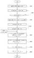
도 2는 본 발명에 따른 착용식 로봇의 사용자 조작 의도 토크 추출방법의 실시예를 도시한 순서도이다.1 is a conceptual diagram of a robot to which the present invention can be applied;
2 is a flowchart illustrating an embodiment of a method for extracting a user manipulation intention torque of a wearable robot according to the present invention.
도 1을 참조하면, 본 발명이 적용될 수 있는 로봇은 작업 대상인 중량물을 홀딩할 수 있도록 그리퍼(1)가 구비되고, 사용자가 조작력을 인가할 수 있도록 핸들(3)이 설치되며, 다수의 관절(5)로 연결되어, 상기 관절에 구비된 모터의 전류 제어를 통해 궁극적으로 상기 그리퍼(1)가 상기 중량물을 홀딩한 상태로 상기 핸들(3)에 가하는 사용자의 의도 토크에 따라 동작하여 상기 중량물을 이동시킬 수 있도록 구성되며, 상기 그리퍼(1)와 핸들(3) 사이에는 가속도센서(7)가 장착된다.
Referring to FIG. 1, a robot to which the present invention can be applied is provided with a
도 2를 참조하면, 본 발명 착용식 로봇의 사용자 조작 의도 토크 추출방법의 실시예는 로봇 자체의 동역학 방정식을 만족하는 상기 로봇의 구동기 토크 τa 를 구하는 선처리단계(S10)와; 로봇의 그리퍼(1)에 중량물이 홀딩된 상태로 상기 중량물을 상기 로봇의 컨트롤러가 설정한 소정의 잡포지션(job position)을 향해 이동시키는 예비구동단계(S20)와; 상기 예비구동단계(S20) 수행시 상기 로봇의 관절에서 소요된 전류 변화를 이용하여, 상기 예비구동단계(S20) 완료되어 상기 잡포지션에서의 상기 중량물에 의해 추가된 토크 τe(job)를 산출하는 추가토크산출단계(S30)와; 상기 선처리단계(S10)에서 구해진 구동기 토크와 상기 추가토크산출단계(S30)에서 산출된 추가 토크 및 상기 중량물의 위치를 이용하여 상기 중량물의 질량 me을 산출하는 질량산출단계(S40)와; 상기 로봇의 핸들에 사용자가 조작력을 가하여 상기 그리퍼가 중량물을 홀딩한 상태에서 이동할 때 가속도센서에서 측정된 가속도와 상기 질량산출단계(S40)에서 산출된 질량에 의해 상기 중량물에 의한 외력을 계산하는 외력산출단계(S50)와; 상기 외력산출단계(S50)에서의 외력을 이용하여 상기 외력에 의한 토크 τe 를 계산하는 외력토크산출단계(S60)와; 상기 그리퍼(1)에 상기 중량물이 홀딩된 상태에서 사용자가 핸들(3)에 사용자 의도 토크를 가하여 상기 로봇이 움직였을 때, 상기 로봇의 관절에서 소요되는 전류 변화를 이용하여 상기와 같은 움직임에 필요한 전체 토크 τ를 산출하는 전체토크산출단계(S70)와; 상기 전체토크산출단계(S70)에서 산출된 전체 토크 τ로부터 상기 로봇의 구동기 토크 τa 및 상기 외력에 의한 토크 τe 를 차감하여 상기 사용자 의도 토크 τh 를 산출하는 의도토크산출단계(S80)를 포함하여 구성된다.
2, an embodiment of a method for extracting a user manipulation intention torque of a wearable robot according to the present invention includesa preprocessing step (S10) of obtaininga driver torque τa of the robot that satisfies a dynamic equation of the robot itself; A preliminary driving step (S20) for moving the heavy object toward a predetermined job position set by the controller of the robot while the heavy object is held in the
즉, 로봇의 그리퍼(1)에 중량물을 홀딩하지 않은 상태로 상기 선처리단계(S10)를 수행하여 상기 로봇 자체의 규격과 물리적 및 기하학적 특성에 따른 구동기의 토크를 구하고, 상기 그리퍼(1)에 임의의 중량물을 홀딩한 상태에서 상기 예비구동단계(S20)와 추가토크산출단계(S30) 및 상기 질량산출단계(S40)를 수행하여 상기 중량물의 질량을 구하고, 그에 따른 외력과 토크를 산출한 후, 사용자가 상기 핸들(3)에 조작력을 가하면, 상기 전체토크산출단계(S70)와 의도토크산출단계(S80)를 통해 사용자가 의도하는 토크를 산출하도록 하는 것이다.That is, the preprocessing step (S10) is performed without holding a heavy object in the
따라서, 상기 선처리단계(S10)는 별도로 미리 수행되어 있는 상황에서, 상기 그리퍼(1)가 다른 중량물을 홀딩할 때마다 상기 예비구동단계(S20) 이후의 과정만을 수행하여 사용자 의도 토크를 산출하도록 구성하는 것이 바람직할 것이다.
Therefore, the pre-processing step (S10) is configured to calculate the user's intention torque by performing only the process after the preliminary driving step (S20) whenever the
상기 선처리단계(S10)의 동역학 방정식은 상기 로봇의 그리퍼(1)에 상기 중량물이 홀딩되지 않은 상태로, 상기 로봇의 각 관절에서의 각도 변화에 따른 로봇 각 부분의 관성, 마찰 및 중력의 함수가 상기 구동기 토크와 이루는 관계를 나타내도록 하기의 수식과 같이 구성된다.The dynamic equation of the pre-processing step (S10) is a function of the inertia, friction and gravity of each part of the robot according to the angle change in each joint of the robot in the state that the weight is not held in the gripper (1) of the robot It is configured as shown in the following formula so as to represent the relationship between the driver torque.

Ma: 로봇 자체의 규격에 따른 관성Ma : Inertia according to the robot's own standard
Ca: 로봇 자체의 규격에 따른 각 관절에서의 원심력에 의한 마찰Ca : Friction by centrifugal force at each joint according to the robot's own standard
Ga: 로봇 자체의 규격에 따른 중력Ga : Gravity according to the robot's own specifications
τa: 구동기 토크τa : actuator torque
q: 관절의 각도q: angle of the joint
상기 수식에서 관성항과 중력항은 로봇 자체의 규격에 의해 결정되며, 상기 마찰항은 실험에 의해 결정되는 값이고, 상기 구동기 토크는 상기 그리퍼(1)에 중량물이 홀딩되지 않은 상태에서 상기 동역학 방정식을 만족하도록 상기 로봇을 구동하는 데에 소요되는 각 관절에서의 전류 변화에 의해 산출되게 된다.
In the above formula, the inertia term and the gravity term are determined by the specifications of the robot itself, and the friction term is a value determined by an experiment, and the actuator torque is the dynamic equation in a state in which no weight is held in the
상기 예비구동단계(S20)의 상기 잡포지션은 상기 로봇의 컨트롤러가 상기 중량물을 홀딩한 초기 위치로부터 이격된 다른 위치로서 상기 중량물에 의해 상기 로봇에서 소요되는 토크의 변화가 적절히 감지될 수 있는 위치로 설정되는 것이 바람직한 바, 주로 상기 중량물을 홀딩한 초기 위치로부터 상방에 인접하게 위치한 지점이 선택됨으로써, 상기 예비구동단계(S20)에서 중량물 추가에 의한 영향이 가장 큰 수직 방향 변위를 형성할 수 있도록 하고, 신속한 예비구동단계(S20)의 완료가 가능하도록 할 수 있을 것이다.
The job position of the preliminary driving step (S20) is another position spaced apart from an initial position at which the controller of the robot holds the heavy object to a position where a change in torque required by the robot can be properly sensed by the heavy object. It is preferable to be set, mainly by selecting a point located adjacent to the upper position from the initial position holding the heavy object, so that the effect of the weight addition in the preliminary driving step (S20) can form the largest vertical displacement In this case, it may be possible to complete the quick preliminary driving step (S20).
상기 추가토크산출단계(S30)는 상기 예비구동단계(S20)가 완료되어 상기 로봇의 컨트롤러가 상기 그리퍼를 상기 잡포지션을 향해 구동 완료한 상태에서의 상기 로봇의 관절에서 발생된 전류 변화에 의해, 상기 중량물에 의해 추가된 토크 τe(job)를 산출한다.
The additional torque calculation step (S30) is due to the current change generated in the joint of the robot when the preliminary driving step (S20) is completed and the controller of the robot has completed driving the gripper toward the job position, The torque?E (job) added by the weight is calculated.
상기 질량산출단계(S40)에서는 상기 잡포지션에 정지해 있는 상기 로봇의 자세에 따른 기하학적 계산에 의해 상기 중량물의 위치를 산출하고, 하기의 수식에 의하여 상기 중량물의 질량을 산출한다.In the mass calculation step (S40), the position of the heavy object is calculated by geometric calculation according to the attitude of the robot stopped at the job position, and the mass of the heavy object is calculated by the following formula.

Ma,e: 로봇 자체의 규격 및 중량물에 따른 관성Ma, e : Inertia according to the size and weight of the robot itself
Ca,e: 로봇 자체의 규격 및 중량물에 따른 각 관절에서의 원심력에 의한 마찰Ca, e : Friction due to centrifugal force at each joint according to the robot's own specification and weight
Ga,e: 로봇 자체의 규격 및 중량물에 따른 중력Ga, e : Gravity according to the size and weight of robot itself
τa: 구동기 토크τa : actuator torque
τe(job): 잡포지션에서의 중량물에 의한 추가 토크τe (job) : additional torque by heavy material in the job position
q: 관절의 각도
q: angle of the joint
여기서, 상기 구동기 토크 τa 와 잡포지션에서의 중량물에 의한 추가토크 τe(job)는 상기 선처리단계(S10)와 추가토크산출단계(S30)에서 이미 구해지고, 상기 관성항과 마찰항은 상기 로봇이 상기 예비구동단계(S20) 종료후 잡포지션에서 정지 상태이므로 상기 관절의 각도 변화가 0이므로 모두 0가 되고, 상기 중력항만 남게 되므로, 상기 로봇의 기하학적 위치관계에 의해 상기 중량물의 위치에 의한 거리가 구해져서, 상기 중량물의 질량을 산출할 수 있게 되는 것이다.
Here, the additional torque τe (job) due to the driver torque τa and the weight in the job position is already obtained in the pretreatment step S10 and the additional torque calculation step S30, and the inertia term and the friction term are Since the robot is stationary in the job position after the preliminary driving step (S20), the angle change of the joints is 0, and thus all are zero, and only the gravity term remains. Therefore, due to the geometric positional relationship of the robot, The distance is obtained, so that the mass of the heavy product can be calculated.
참고로, 상기 예비구동단계(S20)가 완료된 상태는 실질적으로 상기 로봇의 컨트롤러가 당초 목표로 하였던 잡포지션에 도달하지는 못한 상태일 것이다. 즉, 상기 로봇의 컨트롤러는 중량물의 질량을 알지 못하는 상태에서 상기 선처리단계(S10)에서 결정된 구동기 토크로 목표하는 잡포지션에 도달하는 데에 필요한 전류를 각 관절의 모터에 제공함으로써 상기 예비구동단계(S20)를 완료하게 되므로, 실제로는 상기 중량물에 의해 잡포지션에 정확히 도달하지 못하기 때문에, 상기 예비구동단계(S20)가 완료된 상태의 로봇의 기하학적 위치관계에 의해 상기 중량물의 위치를 산출하는 것이다.
For reference, the state in which the preliminary driving step S20 is completed may be a state in which the controller of the robot does not reach the job position originally targeted. That is, the controller of the robot provides the current required to reach the target job position with the driver torque determined in the preprocessing step (S10) without knowing the mass of the heavy object by providing the motor of each joint with the preliminary driving step ( Since the S20 is completed, the position of the weight is calculated by the geometric positional relationship of the robot in the state in which the preliminary driving step S20 is completed because the weight position is not actually reached by the weight.
상기와 같이 로봇의 그리퍼에 홀딩된 중량물의 질량 me을 알게 되면, 이후에는 사용자가 핸들에 조작력을 가하여 로봇의 작동이 이루어지는 경우에 하기와 같은 단계들에 의해 사용자 의도 토크 τh를 구해낼 수 있게 된다.
As described above, when the mass me of the weight held in the gripper of the robot is known, the user can calculate the user's intentional torque τh by the following steps when the user applies the operating force to the handle to operate the robot. do.
즉, 사용자가 상기 핸들에 조작력을 가하여 상기 중량물이 이동하면, 상기 외력산출단계(S50)에서 상기 가속도센서에 의해 그 가속도 a를 측정하여 상기 질량산출단계(S40)에서 산출된 상기 중량물의 질량 me을 곱함으로써, 상기 중량물에 의해 가해지는 외력 fe을 계산하는 것이다.
That is, when the user applies the operating force to the handle to move the weight, the mass m of the weight calculated in the mass calculation step (S40) by measuring the acceleration a by the acceleration sensor in the external force calculation step (S50) By multiplyinge , the external force fe exerted by the weight is calculated.
상기 외력토크산출단계(S60)에서는 상기 외력산출단계(S50)에서 산출된 상기 중량물에 의한 외력 fe에, 상기 로봇의 각 관절에 대한 위치관계를 특정하는 자코비안 트랜스포즈 JT를 곱하여, 상기 중량물의 위치변화에 따른 그 때마다의 외력 토크 τe를 산출하게 된다.In the external torque calculation step (S60) by multiplying the external force fe by the weight product calculated in the external force calculation step (S50) by the Jacobian transpose JT specifying the positional relationship to each joint of the robot, The external force torque?E at each time according to the positional change of the heavy object is calculated.
즉, 상기 추가토크산출단계(S30)에서의 중량물에 의해 추가된 토크 τe(job)는 상기 중량물이 상기 잡포지션에 위치한 상태에서 계산된 것이고, 상기 외력토크산출단계(S60)에서의 외력토크 τe는 상기 중량물이 잡포지션을 떠나서 이동한 다른 위치에서 상기 중량물에 의해 작용하는 외력에 의한 토크인 것이다.
That is, the torque τe (job) added by the weight in the additional torque calculation step (S30) is calculated in the state where the weight is located in the job position, the external force torque in the external torque calculation step (S60) τe is a torque due to an external force acting by the weight at another position where the weight moves away from the job position.
상기 의도토크산출단계(S80)에서는 다음의 수식에 의하여 사용자가 상기 로봇을 구동하기 위해 작용한 의도 토크를 산출한다.In the intention torque calculation step (S80), the intention torque acted by the user to drive the robot is calculated by the following equation.

τh: 사용자 의도 토크τh : user intent torque
τ: 전체 토크τ: total torque
τa: 구동기 토크τa : actuator torque
τe: 중량물의 위치변화에 따른 그 때마다의 외력 토크
τe : External force torque at each time according to change of position of heavy object
여기서, 상기 전체 토크 τ는 상기 전체토크산출단계(S70)에서 구해지는 것으로서, 사용자가 로봇의 핸들(3)에 조작력을 가하여 상기 그리퍼(1)에 중량물이 홀딩된 상태로 이동이 이루어졌을 때 상기 로봇의 관절에서 소요되는 상기 구동기에서 작용하는 전체적인 토크를 의미하는 바, 여기에는 상기 로봇 자체만을 구동하기 위해 작용하는 상기 구동기 토크 τa와 상기 중량물이 추가됨에 의해 작용하게 되는 외력에 의한 외력토크 τe 및 사용자 의도 토크 τh가 포함된 것이므로, 이 전체토크 τ로부터 상기 구동기 토크 τa와 중량물에 의한 외력 토크 τe를 차감하면, 사용자에 의한 의도 토크 τh만을 구할 수 있는 것이다.
Here, the total torque τ is obtained in the total torque calculation step (S70), when the user applies the operating force to the handle (3) of the robot to move the gripper (1) in the state of holding a heavy object Means the overall torque acting on the driver to be taken in the joint of the robot, the external torque torque τ caused by the external force that is acted by the addition of the driver torque τa and the weight to act to drive only the robot itselfSince e and the user intention torque τh are included, only the intention torque τh by the user can be obtained by subtracting the driver torque τa and the external force torque τe by the heavy object from the total torque τ.
본 발명은 특정한 실시예에 관련하여 도시하고 설명하였지만, 이하의 특허청구범위에 의해 제공되는 본 발명의 기술적 사상을 벗어나지 않는 한도 내에서, 본 발명이 다양하게 개량 및 변화될 수 있다는 것은 당업계에서 통상의 지식을 가진 자에게 있어서 자명할 것이다.While the present invention has been particularly shown and described with reference to specific embodiments thereof, it will be understood by those skilled in the art that various changes in form and details may be made therein without departing from the spirit and scope of the invention as defined by the following claims It will be apparent to those of ordinary skill in the art.
1; 그리퍼
3; 핸들
5; 관절
7; 가속도센서
S10; 선처리단계
S20; 예비구동단계
S30; 추가토크산출단계
S40; 질량산출단계
S50; 외력산출단계
S60; 외력토크산출단계
S70; 전체토크산출단계
S80; 의도토크산출단계One; Gripper
3; handle
5; joint
7; Acceleration sensor
S10; Preprocessing Step
S20; Preliminary Driving Stage
S30; Additional torque calculation step
S40; Mass calculation step
S50; External force calculation stage
S60; External torque calculation stage
S70; Total torque calculation step
S80; Intent torque calculation stage
Claims (7)
Translated fromKorean로봇의 그리퍼(1)에 중량물이 홀딩된 상태로 상기 중량물을 상기 로봇의 컨트롤러가 설정한 소정의 잡포지션을 향해 이동시키는 예비구동단계(S20)와;
상기 예비구동단계(S20) 수행시 상기 로봇의 관절에서 소요된 전류 변화를 이용하여, 상기 예비구동단계(S20) 완료 상태에서의 상기 잡포지션에서의 중량물에 의해 추가된 토크를 산출하는 추가토크산출단계(S30)와;
상기 선처리단계(S10)에서 구해진 구동기 토크와 상기 추가토크산출단계(S30)에서 산출된 추가 토크 및 상기 중량물의 위치를 이용하여 상기 중량물의 질량을 산출하는 질량산출단계(S40)와;
상기 로봇의 핸들에 사용자가 조작력을 가하여 상기 그리퍼가 중량물을 홀딩한 상태에서 이동할 때 가속도센서에서 측정된 가속도와 상기 질량산출단계(S40)에서 산출된 질량에 의해 상기 중량물에 의한 외력을 계산하는 외력산출단계(S50)와;
상기 외력산출단계(S50)에서의 외력을 이용하여 상기 중량물의 위치변화에 따른 외력 토크를 계산하는 외력토크산출단계(S60)와;
상기 그리퍼(1)에 상기 중량물이 홀딩된 상태에서 사용자가 핸들(3)에 사용자 의도 토크를 가하여 상기 로봇이 움직였을 때, 상기 로봇의 관절에서 소요되는 전류 변화를 이용하여 상기와 같은 움직임에 필요한 전체 토크를 산출하는 전체토크산출단계(S70)와;
상기 전체토크산출단계(S70)에서 산출된 전체 토크로부터 상기 로봇의 구동기 토크 및 상기 외력에 의한 토크를 차감하여 상기 사용자 의도 토크를 산출하는 의도토크산출단계(S80);
를 포함하여 구성된 것을 특징으로 하는 착용식 로봇의 사용자 조작 의도 토크 추출방법.A preprocessing step (S10) of obtaining driver torque of the robot that satisfies the dynamic equation of the robot itself;
A preliminary driving step (S20) for moving the heavy object toward a predetermined job position set by the controller of the robot while the heavy object is held in the gripper (1) of the robot;
Additional torque calculation for calculating the torque added by the weight in the job position in the completion state of the preliminary driving step (S20) by using the current change in the joint of the robot when performing the preliminary driving step (S20). Step S30;
A mass calculation step (S40) of calculating the mass of the heavy weight using the driver torque obtained in the preprocessing step (S10), the additional torque calculated in the additional torque calculating step (S30), and the position of the heavy weight;
External force for calculating the external force due to the weight by the acceleration calculated by the acceleration sensor and the mass calculated in the mass calculation step (S40) when the user applies the manipulation force to the handle of the robot and moves in the state where the gripper holds the weight. Calculating step S50;
An external force torque calculating step (S60) of calculating an external force torque according to the positional change of the weight using the external force in the external force calculating step (S50);
When the robot is moved by applying a user's intention torque to the handle 3 while the heavy object is held on the gripper 1, the whole necessary for the above movement is made by using the current change required in the joint of the robot. A total torque calculation step (S70) of calculating torque;
An intention torque calculation step (S80) of calculating the user intention torque by subtracting torque from the driver torque and the external force of the robot from the total torque calculated in the total torque calculation step (S70);
User operation intention torque extraction method of the wearable robot, characterized in that configured to include.
상기 선처리단계(S10)의 동역학 방정식은 상기 로봇의 그리퍼(1)에 상기 중량물이 홀딩되지 않은 상태로, 상기 로봇의 각 관절에서의 각도 변화에 따른 로봇 각 부분의 관성, 마찰 및 중력의 함수가 상기 구동기 토크와 이루는 관계를 나타내도록 하기의 수식과 같이 구성된 것
을 특징으로 하는 착용식 로봇의 사용자 조작 의도 토크 추출방법.

Ma: 로봇 자체의 규격에 따른 관성
Ca: 로봇 자체의 규격에 따른 각 관절에서의 원심력에 의한 마찰
Ga: 로봇 자체의 규격에 따른 중력
τa: 구동기 토크
q: 관절의 각도The method according to claim 1,
The dynamic equation of the pre-processing step (S10) is a function of the inertia, friction and gravity of each part of the robot according to the angle change in each joint of the robot in the state that the weight is not held in the gripper (1) of the robot It is configured as shown in the following formula to show the relationship between the driver torque
Method of extracting the user's intention torque of the wearable robot, characterized in that.
Ma : Inertia according to the robot's own standard
Ca : Friction by centrifugal force at each joint according to the robot's own standard
Ga : Gravity according to the robot's own specifications
τa : actuator torque
q: angle of the joint
상기 예비구동단계(S20)의 상기 잡포지션은 상기 로봇의 컨트롤러가 상기 중량물을 홀딩한 초기 위치로부터 이격된 다른 위치로서 상기 중량물에 의해 상기 로봇에서 소요되는 토크의 변화가 적절히 감지될 수 있는 위치로 설정되는 것
을 특징으로 하는 착용식 로봇의 사용자 조작 의도 토크 추출방법.The method according to claim 1,
The job position of the preliminary driving step (S20) is another position spaced apart from an initial position at which the controller of the robot holds the heavy object to a position where a change in torque required by the robot can be properly sensed by the heavy object. Set
Method of extracting the user's intention torque of the wearable robot, characterized in that.
상기 질량산출단계(S40)에서는
상기 잡포지션에 정지해 있는 상기 로봇의 자세에 따른 기하학적 계산에 의해 상기 중량물의 위치를 산출하고;
하기의 수식에 의하여 상기 중량물의 질량을 산출하는 것
을 특징으로 하는 착용식 로봇의 사용자 조작 의도 토크 추출방법.

Ma,e: 로봇 자체의 규격 및 중량물에 따른 관성
Ca,e: 로봇 자체의 규격 및 중량물에 따른 각 관절에서의 원심력에 의한 마찰
Ga,e: 로봇 자체의 규격 및 중량물에 따른 중력
τa: 구동기 토크
τe(job): 잡포지션에서의 중량물에 의한 추가 토크
q: 관절의 각도The method according to claim 1,
In the mass calculation step (S40)
Calculating the position of the heavy object by geometric calculation according to the attitude of the robot stationary at the job position;
Calculating the mass of the weight by the following formula
Method of extracting the user's intention torque of the wearable robot, characterized in that.
Ma, e : Inertia according to the size and weight of the robot itself
Ca, e : Friction due to centrifugal force at each joint according to the robot's own specification and weight
Ga, e : Gravity according to the size and weight of robot itself
τa : actuator torque
τe (job) : additional torque by heavy material in the job position
q: angle of the joint
상기 외력토크산출단계(S60)에서는 상기 외력산출단계(S50)에서 산출된 상기 중량물에 의한 외력에, 상기 로봇의 각 관절에 대한 위치관계를 특정하는 자코비안 트랜스포즈를 곱하여 상기 중량물의 위치변화에 따른 그 때마다의 외력 토크 τe 를 산출하는 것
을 특징으로 하는 착용식 로봇의 사용자 조작 의도 토크 추출방법.The method according to claim 1,
In the external torque calculation step (S60), the external force by the weight product calculated in the external force calculation step (S50) is multiplied by a Jacobian transpose specifying a positional relationship to each joint of the robot to the position change of the weight product. To calculate the external force torque τe at each time
Method of extracting the user's intention torque of the wearable robot, characterized in that.
상기 의도토크산출단계(S80)에서는 다음의 수식에 의하여 사용자가 상기 로봇을 구동하기 위해 작용한 의도 토크를 산출하는 것
을 특징으로 하는 착용식 로봇의 사용자 조작 의도 토크 추출방법.

τh: 사용자 의도 토크
τ: 전체 토크
τa: 구동기 토크
τe: 중량물의 위치변화에 따른 그 때마다의 외력 토크The method according to claim 1,
In the intention torque calculation step (S80) to calculate the intention torque acted by the user to drive the robot by the following formula
Method of extracting the user's intention torque of the wearable robot, characterized in that.
τh : user intent torque
τ: total torque
τa : actuator torque
τe : External force torque at each time according to change of position of heavy object
중량물을 홀딩한 채로 상기 중량물을 소정의 잡포지션으로 이동시키면서 상기 로봇의 관절에서 소요된 전류 변화에 의해 상기 잡포지션에서의 중량물 추가에 따른 토크 τe(job)를 산출하며;
상기 구동기 토크와 중량물 추가에 따른 토크 및 상기 중량물의 위치를 이용하여 상기 중량물의 질량 me을 산출하고;
상기 로봇의 핸들에 사용자가 조작력을 가하여 상기 그리퍼가 중량물을 홀딩한 상태에서 이동할 때 가속도센서에서 측정된 가속도 a와 상기 중량물의 질량 me에 의해 상기 중량물에 의한 외력 fe 및 토크 τe 를 계산하며;
사용자 조작에 의해 상기 로봇이 움직일 때, 상기 로봇의 관절에서 소요되는 전류 변화를 이용하여 상기와 같은 움직임에 필요한 전체 토크 τ를 산출하고;
상기 산출된 전체 토크 τ로부터 상기 로봇의 구동기 토크 τa 및 상기 외력에 의한 토크 τe 를 차감하여 상기 사용자 의도 토크 τh 를 산출하는 것
을 특징으로 하는 착용식 로봇의 사용자 조작 의도 토크 추출방법.Obtains the driver torque τa of the robot without holding the heavy object;
Calculating the torque?E (job) according to the addition of the weight in the job position by changing the current required at the joint of the robot while moving the weight to a predetermined job position while holding the weight;
Calculating the mass me of the weight using the driver torque and the torque according to the weight addition and the position of the weight;
The external force fe and the torque τe due to the weight are calculated by the acceleration a measured by the acceleration sensor and the mass me of the weight when the user moves the gripper by holding the weight to the handle of the robot. To;
Calculating the total torque τ required for such a movement by using a change in current required at a joint of the robot when the robot moves by a user operation;
Calculating the user intended torque τh by subtracting the driver torque τa of the robot and the torque τe caused by the external force from the calculated total torque τ.
Method of extracting the user's intention torque of the wearable robot, characterized in that.
Priority Applications (2)
| Application Number | Priority Date | Filing Date | Title |
|---|---|---|---|
| KR1020120000796AKR101305819B1 (en) | 2012-01-04 | 2012-01-04 | Manipulating intention torque extracting method of wearable robot |
| US13/529,131US9114524B2 (en) | 2012-01-04 | 2012-06-21 | Method of operating a wearable robot |
Applications Claiming Priority (1)
| Application Number | Priority Date | Filing Date | Title |
|---|---|---|---|
| KR1020120000796AKR101305819B1 (en) | 2012-01-04 | 2012-01-04 | Manipulating intention torque extracting method of wearable robot |
Publications (2)
| Publication Number | Publication Date |
|---|---|
| KR20130080076Atrue KR20130080076A (en) | 2013-07-12 |
| KR101305819B1 KR101305819B1 (en) | 2013-09-06 |
Family
ID=48695526
Family Applications (1)
| Application Number | Title | Priority Date | Filing Date |
|---|---|---|---|
| KR1020120000796AActiveKR101305819B1 (en) | 2012-01-04 | 2012-01-04 | Manipulating intention torque extracting method of wearable robot |
Country Status (2)
| Country | Link |
|---|---|
| US (1) | US9114524B2 (en) |
| KR (1) | KR101305819B1 (en) |
Families Citing this family (31)
| Publication number | Priority date | Publication date | Assignee | Title |
|---|---|---|---|---|
| US9566710B2 (en) | 2011-06-02 | 2017-02-14 | Brain Corporation | Apparatus and methods for operating robotic devices using selective state space training |
| JP5835254B2 (en)* | 2013-03-15 | 2015-12-24 | 株式会社安川電機 | Robot system and control method of robot system |
| US9764468B2 (en) | 2013-03-15 | 2017-09-19 | Brain Corporation | Adaptive predictor apparatus and methods |
| US9242372B2 (en) | 2013-05-31 | 2016-01-26 | Brain Corporation | Adaptive robotic interface apparatus and methods |
| US9314924B1 (en) | 2013-06-14 | 2016-04-19 | Brain Corporation | Predictive robotic controller apparatus and methods |
| US9792546B2 (en) | 2013-06-14 | 2017-10-17 | Brain Corporation | Hierarchical robotic controller apparatus and methods |
| US9384443B2 (en) | 2013-06-14 | 2016-07-05 | Brain Corporation | Robotic training apparatus and methods |
| US9579789B2 (en) | 2013-09-27 | 2017-02-28 | Brain Corporation | Apparatus and methods for training of robotic control arbitration |
| US9597797B2 (en) | 2013-11-01 | 2017-03-21 | Brain Corporation | Apparatus and methods for haptic training of robots |
| US9463571B2 (en) | 2013-11-01 | 2016-10-11 | Brian Corporation | Apparatus and methods for online training of robots |
| KR102172975B1 (en)* | 2013-12-10 | 2020-11-02 | 삼성전자주식회사 | Wearable robot and control method for the same |
| US9358685B2 (en)* | 2014-02-03 | 2016-06-07 | Brain Corporation | Apparatus and methods for control of robot actions based on corrective user inputs |
| US9630318B2 (en) | 2014-10-02 | 2017-04-25 | Brain Corporation | Feature detection apparatus and methods for training of robotic navigation |
| US9717387B1 (en) | 2015-02-26 | 2017-08-01 | Brain Corporation | Apparatus and methods for programming and training of robotic household appliances |
| KR102288884B1 (en)* | 2015-08-07 | 2021-08-13 | 현대자동차주식회사 | Method and system of controlling wearable robot |
| US10471594B2 (en)* | 2015-12-01 | 2019-11-12 | Kindred Systems Inc. | Systems, devices, and methods for the distribution and collection of multimodal data associated with robots |
| DE102017000063B4 (en)* | 2016-01-14 | 2019-10-31 | Fanuc Corporation | Robot device with learning function |
| US10241514B2 (en) | 2016-05-11 | 2019-03-26 | Brain Corporation | Systems and methods for initializing a robot to autonomously travel a trained route |
| US9987752B2 (en) | 2016-06-10 | 2018-06-05 | Brain Corporation | Systems and methods for automatic detection of spills |
| US10282849B2 (en) | 2016-06-17 | 2019-05-07 | Brain Corporation | Systems and methods for predictive/reconstructive visual object tracker |
| US10016896B2 (en) | 2016-06-30 | 2018-07-10 | Brain Corporation | Systems and methods for robotic behavior around moving bodies |
| US10274325B2 (en) | 2016-11-01 | 2019-04-30 | Brain Corporation | Systems and methods for robotic mapping |
| US10001780B2 (en) | 2016-11-02 | 2018-06-19 | Brain Corporation | Systems and methods for dynamic route planning in autonomous navigation |
| US10723018B2 (en) | 2016-11-28 | 2020-07-28 | Brain Corporation | Systems and methods for remote operating and/or monitoring of a robot |
| US10377040B2 (en) | 2017-02-02 | 2019-08-13 | Brain Corporation | Systems and methods for assisting a robotic apparatus |
| US10852730B2 (en) | 2017-02-08 | 2020-12-01 | Brain Corporation | Systems and methods for robotic mobile platforms |
| US10293485B2 (en) | 2017-03-30 | 2019-05-21 | Brain Corporation | Systems and methods for robotic path planning |
| JP6795540B2 (en)* | 2018-04-24 | 2020-12-02 | ファナック株式会社 | Devices, methods and programs for estimating load weight and center of gravity position using a robot |
| JP7136729B2 (en)* | 2019-03-20 | 2022-09-13 | ファナック株式会社 | Apparatus, method, program, controller and robot system for estimating load weight and center-of-gravity position using a robot |
| CN111618859B (en)* | 2020-06-03 | 2021-04-13 | 杭州键嘉机器人有限公司 | Method for feeding back mechanical arm high-precision force under static or low-speed working condition |
| CN114833804B (en)* | 2022-06-13 | 2024-09-13 | 山东瑞曼智能装备有限公司 | Active power assisting device and method suitable for multiple scenes |
Family Cites Families (9)
| Publication number | Priority date | Publication date | Assignee | Title |
|---|---|---|---|---|
| US5055755A (en)* | 1989-05-31 | 1991-10-08 | Kabushiki Kaisha Toshiba | Distribution control apparatus |
| JP2769947B2 (en)* | 1992-05-15 | 1998-06-25 | 株式会社椿本チエイン | Manipulator position / posture control method |
| JP2000190261A (en) | 1998-12-24 | 2000-07-11 | Toyota Motor Corp | manipulator |
| JP2000218576A (en) | 1999-02-04 | 2000-08-08 | Toshiba Corp | manipulator |
| JP3923053B2 (en)* | 2004-03-31 | 2007-05-30 | ファナック株式会社 | Robot teaching device |
| CN101870112B (en)* | 2006-01-13 | 2011-09-28 | 松下电器产业株式会社 | Device for controlling robot arm |
| KR100753557B1 (en) | 2006-08-23 | 2007-08-30 | 삼성물산 주식회사 | Interface device of the working robot |
| CN102229147B (en)* | 2007-06-27 | 2014-01-29 | 松下电器产业株式会社 | Manipulator control device and control method, robot |
| KR101209779B1 (en) | 2008-04-30 | 2012-12-07 | 현대중공업 주식회사 | Method for estimating load of robot |
- 2012
- 2012-01-04KRKR1020120000796Apatent/KR101305819B1/enactiveActive
- 2012-06-21USUS13/529,131patent/US9114524B2/enactiveActive
Also Published As
| Publication number | Publication date |
|---|---|
| KR101305819B1 (en) | 2013-09-06 |
| US9114524B2 (en) | 2015-08-25 |
| US20130173060A1 (en) | 2013-07-04 |
Similar Documents
| Publication | Publication Date | Title |
|---|---|---|
| KR101305819B1 (en) | Manipulating intention torque extracting method of wearable robot | |
| KR101575487B1 (en) | Method and system for calculating weight and center of gravity of object for robot | |
| JP6484265B2 (en) | Robot system having learning control function and learning control method | |
| KR101305617B1 (en) | Method and system for comtrolling lifting operation of wearable robot | |
| US10751874B2 (en) | Method of teaching robot and robotic arm control device | |
| JP5893666B2 (en) | Robot control device and robot system for robots that move according to force | |
| US8583285B2 (en) | Method and device for stopping a manipulator | |
| WO2014144946A3 (en) | Force responsive power tool | |
| JP2013515313A5 (en) | ||
| US10987742B2 (en) | Method of controlling positioning control apparatus and positioning control apparatus | |
| JP2013043271A5 (en) | ||
| SE1751013A1 (en) | A robotic work tool and a method for use in a robotic work tool comprising a lift and collision detection | |
| JP2016007645A (en) | Multi-joint robot having saving function of arm | |
| EP3272471A3 (en) | Robot apparatus, robot controlling method, program, and recording medium | |
| JP2016087700A (en) | Control equipment having feature of verifying designation of load information | |
| MX2016016747A (en) | METHOD AND DEVICE FOR QUICK AND RELIABLE TOOL CHANGE IN THE FRICTION WELDING PROCESS - AGITATION. | |
| EP2113449A3 (en) | Actuator control device, actuator control method, actuator, robot apparatus, and computer program | |
| JP2016144861A5 (en) | Robot apparatus, control method, article manufacturing method, program, and recording medium | |
| CN102756374A (en) | Robot controller, simple installation-type robot, and method of controlling simple installation-type robot | |
| JP2016221642A5 (en) | ||
| EP3242775A1 (en) | Method for estimation of external forces and torques on a robot arm | |
| CN107438502B (en) | A method of controlling industrial robots by touch | |
| KR20130067369A (en) | Apparatus for extracting drive characteristic of drive part | |
| CN107000209B (en) | Method and device for controlling a drive assembly for moving a tool, in particular a robot-guided tool | |
| JP2013013987A5 (en) | Robot system and component manufacturing method |
Legal Events
| Date | Code | Title | Description |
|---|---|---|---|
| A201 | Request for examination | ||
| PA0109 | Patent application | St.27 status event code:A-0-1-A10-A12-nap-PA0109 | |
| PA0201 | Request for examination | St.27 status event code:A-1-2-D10-D11-exm-PA0201 | |
| PN2301 | Change of applicant | St.27 status event code:A-3-3-R10-R13-asn-PN2301 St.27 status event code:A-3-3-R10-R11-asn-PN2301 | |
| D13-X000 | Search requested | St.27 status event code:A-1-2-D10-D13-srh-X000 | |
| D14-X000 | Search report completed | St.27 status event code:A-1-2-D10-D14-srh-X000 | |
| E902 | Notification of reason for refusal | ||
| PE0902 | Notice of grounds for rejection | St.27 status event code:A-1-2-D10-D21-exm-PE0902 | |
| PG1501 | Laying open of application | St.27 status event code:A-1-1-Q10-Q12-nap-PG1501 | |
| P11-X000 | Amendment of application requested | St.27 status event code:A-2-2-P10-P11-nap-X000 | |
| P13-X000 | Application amended | St.27 status event code:A-2-2-P10-P13-nap-X000 | |
| E701 | Decision to grant or registration of patent right | ||
| PE0701 | Decision of registration | St.27 status event code:A-1-2-D10-D22-exm-PE0701 | |
| GRNT | Written decision to grant | ||
| PR0701 | Registration of establishment | St.27 status event code:A-2-4-F10-F11-exm-PR0701 | |
| PR1002 | Payment of registration fee | St.27 status event code:A-2-2-U10-U11-oth-PR1002 Fee payment year number:1 | |
| PG1601 | Publication of registration | St.27 status event code:A-4-4-Q10-Q13-nap-PG1601 | |
| R18-X000 | Changes to party contact information recorded | St.27 status event code:A-5-5-R10-R18-oth-X000 | |
| PR1001 | Payment of annual fee | St.27 status event code:A-4-4-U10-U11-oth-PR1001 Fee payment year number:4 | |
| PR1001 | Payment of annual fee | St.27 status event code:A-4-4-U10-U11-oth-PR1001 Fee payment year number:5 | |
| FPAY | Annual fee payment | Payment date:20180829 Year of fee payment:6 | |
| PR1001 | Payment of annual fee | St.27 status event code:A-4-4-U10-U11-oth-PR1001 Fee payment year number:6 | |
| R18-X000 | Changes to party contact information recorded | St.27 status event code:A-5-5-R10-R18-oth-X000 | |
| FPAY | Annual fee payment | Payment date:20190827 Year of fee payment:7 | |
| PR1001 | Payment of annual fee | St.27 status event code:A-4-4-U10-U11-oth-PR1001 Fee payment year number:7 | |
| PR1001 | Payment of annual fee | St.27 status event code:A-4-4-U10-U11-oth-PR1001 Fee payment year number:8 | |
| PR1001 | Payment of annual fee | St.27 status event code:A-4-4-U10-U11-oth-PR1001 Fee payment year number:9 | |
| PR1001 | Payment of annual fee | St.27 status event code:A-4-4-U10-U11-oth-PR1001 Fee payment year number:10 | |
| PR1001 | Payment of annual fee | St.27 status event code:A-4-4-U10-U11-oth-PR1001 Fee payment year number:11 | |
| PR1001 | Payment of annual fee | St.27 status event code:A-4-4-U10-U11-oth-PR1001 Fee payment year number:12 | |
| PR1001 | Payment of annual fee | St.27 status event code:A-4-4-U10-U11-oth-PR1001 Fee payment year number:13 |