KR20130070597A - Image processor and image processing method - Google Patents
Image processor and image processing methodDownload PDFInfo
- Publication number
- KR20130070597A KR20130070597AKR1020127029404AKR20127029404AKR20130070597AKR 20130070597 AKR20130070597 AKR 20130070597AKR 1020127029404 AKR1020127029404 AKR 1020127029404AKR 20127029404 AKR20127029404 AKR 20127029404AKR 20130070597 AKR20130070597 AKR 20130070597A
- Authority
- KR
- South Korea
- Prior art keywords
- filter
- block
- unit
- image
- image data
- Prior art date
- Legal status (The legal status is an assumption and is not a legal conclusion. Google has not performed a legal analysis and makes no representation as to the accuracy of the status listed.)
- Granted
Links
Images


Classifications
- H—ELECTRICITY
- H04—ELECTRIC COMMUNICATION TECHNIQUE
- H04N—PICTORIAL COMMUNICATION, e.g. TELEVISION
- H04N19/00—Methods or arrangements for coding, decoding, compressing or decompressing digital video signals
- H04N19/10—Methods or arrangements for coding, decoding, compressing or decompressing digital video signals using adaptive coding
- H04N19/134—Methods or arrangements for coding, decoding, compressing or decompressing digital video signals using adaptive coding characterised by the element, parameter or criterion affecting or controlling the adaptive coding
- H04N19/136—Incoming video signal characteristics or properties
- H04N19/14—Coding unit complexity, e.g. amount of activity or edge presence estimation
- H—ELECTRICITY
- H04—ELECTRIC COMMUNICATION TECHNIQUE
- H04N—PICTORIAL COMMUNICATION, e.g. TELEVISION
- H04N19/00—Methods or arrangements for coding, decoding, compressing or decompressing digital video signals
- H04N19/10—Methods or arrangements for coding, decoding, compressing or decompressing digital video signals using adaptive coding
- H04N19/102—Methods or arrangements for coding, decoding, compressing or decompressing digital video signals using adaptive coding characterised by the element, parameter or selection affected or controlled by the adaptive coding
- H04N19/117—Filters, e.g. for pre-processing or post-processing
- H—ELECTRICITY
- H04—ELECTRIC COMMUNICATION TECHNIQUE
- H04N—PICTORIAL COMMUNICATION, e.g. TELEVISION
- H04N19/00—Methods or arrangements for coding, decoding, compressing or decompressing digital video signals
- H04N19/10—Methods or arrangements for coding, decoding, compressing or decompressing digital video signals using adaptive coding
- H04N19/134—Methods or arrangements for coding, decoding, compressing or decompressing digital video signals using adaptive coding characterised by the element, parameter or criterion affecting or controlling the adaptive coding
- H04N19/157—Assigned coding mode, i.e. the coding mode being predefined or preselected to be further used for selection of another element or parameter
- H—ELECTRICITY
- H04—ELECTRIC COMMUNICATION TECHNIQUE
- H04N—PICTORIAL COMMUNICATION, e.g. TELEVISION
- H04N19/00—Methods or arrangements for coding, decoding, compressing or decompressing digital video signals
- H04N19/10—Methods or arrangements for coding, decoding, compressing or decompressing digital video signals using adaptive coding
- H04N19/169—Methods or arrangements for coding, decoding, compressing or decompressing digital video signals using adaptive coding characterised by the coding unit, i.e. the structural portion or semantic portion of the video signal being the object or the subject of the adaptive coding
- H04N19/17—Methods or arrangements for coding, decoding, compressing or decompressing digital video signals using adaptive coding characterised by the coding unit, i.e. the structural portion or semantic portion of the video signal being the object or the subject of the adaptive coding the unit being an image region, e.g. an object
- H04N19/176—Methods or arrangements for coding, decoding, compressing or decompressing digital video signals using adaptive coding characterised by the coding unit, i.e. the structural portion or semantic portion of the video signal being the object or the subject of the adaptive coding the unit being an image region, e.g. an object the region being a block, e.g. a macroblock
- H—ELECTRICITY
- H04—ELECTRIC COMMUNICATION TECHNIQUE
- H04N—PICTORIAL COMMUNICATION, e.g. TELEVISION
- H04N19/00—Methods or arrangements for coding, decoding, compressing or decompressing digital video signals
- H04N19/44—Decoders specially adapted therefor, e.g. video decoders which are asymmetric with respect to the encoder
- H—ELECTRICITY
- H04—ELECTRIC COMMUNICATION TECHNIQUE
- H04N—PICTORIAL COMMUNICATION, e.g. TELEVISION
- H04N19/00—Methods or arrangements for coding, decoding, compressing or decompressing digital video signals
- H04N19/60—Methods or arrangements for coding, decoding, compressing or decompressing digital video signals using transform coding
- H—ELECTRICITY
- H04—ELECTRIC COMMUNICATION TECHNIQUE
- H04N—PICTORIAL COMMUNICATION, e.g. TELEVISION
- H04N19/00—Methods or arrangements for coding, decoding, compressing or decompressing digital video signals
- H04N19/80—Details of filtering operations specially adapted for video compression, e.g. for pixel interpolation
- H04N19/82—Details of filtering operations specially adapted for video compression, e.g. for pixel interpolation involving filtering within a prediction loop
- H—ELECTRICITY
- H04—ELECTRIC COMMUNICATION TECHNIQUE
- H04N—PICTORIAL COMMUNICATION, e.g. TELEVISION
- H04N19/00—Methods or arrangements for coding, decoding, compressing or decompressing digital video signals
- H04N19/85—Methods or arrangements for coding, decoding, compressing or decompressing digital video signals using pre-processing or post-processing specially adapted for video compression
- H04N19/86—Methods or arrangements for coding, decoding, compressing or decompressing digital video signals using pre-processing or post-processing specially adapted for video compression involving reduction of coding artifacts, e.g. of blockiness
Landscapes
- Engineering & Computer Science (AREA)
- Multimedia (AREA)
- Signal Processing (AREA)
- Compression Or Coding Systems Of Tv Signals (AREA)
Abstract
Translated fromKorean
Description
Translated fromKorean이 기술은 화상 처리 장치와 화상 처리 방법에 관한 것이다. 구체적으로는 양호한 화질의 복호 화상을 얻을 수 있도록 한다.This technology relates to an image processing apparatus and an image processing method. Specifically, a decoded image of good image quality can be obtained.
최근, 화상 정보를 디지털로서 취급하고, 그 때, 효율이 높은 정보의 전송, 축적을 행하는 장치, 예를 들어 이산 코사인 변환 등의 직교 변환과 움직임 보상에 의해 압축하는 MPEG 등의 방식에 준거한 장치가 방송국이나 일반 가정에 보급되고 있다.Background Art In recent years, image information is treated as digital, and at that time, an apparatus that transmits and accumulates highly efficient information, for example, an apparatus based on a method such as MPEG that is compressed by orthogonal transformation such as discrete cosine transformation and motion compensation. Is spreading to broadcasting stations and homes.
특히, MPEG2(ISO/IEC 13818-2)는 범용 화상 부호화 방식으로서 정의되어 있고, 프로페셔널 용도 및 컨슈머 용도의 광범한 어플리케이션에 현재 널리 사용되고 있다. 이 MPEG2 압축 방식을 사용함으로써, 예를 들어 720×480 화소를 갖는 표준 해상도의 비월 주사 화상이면, 4 내지 8Mbps 부호량(비트 레이트)을 할당함으로써 양호한 화질의 실현이 가능하다. 또한, 1920×1088 화소를 갖는 고해상도의 비월 주사 화상이면 18 내지 22Mbps의 부호량(비트 레이트)을 할당함으로써 양호한 화질의 실현이 가능하다.In particular, MPEG2 (ISO / IEC 13818-2) is defined as a universal picture coding scheme and is now widely used in a wide range of applications for professional and consumer applications. By using this MPEG2 compression method, for example, an interlaced scan image having a standard resolution of 720 x 480 pixels can be realized by assigning a 4 to 8 Mbps code amount (bit rate). In the case of a high resolution interlaced scanning image having 1920x1088 pixels, good image quality can be realized by allocating a code amount (bit rate) of 18 to 22 Mbps.
MPEG2는 주로 방송용으로 적합한 고화질 부호화를 대상으로 하고 있었지만, MPEG1보다 낮은 부호량(비트 레이트), 즉 보다 높은 압축률의 부호화 방식에는 대응하지 못하고 있었다. 휴대 단말의 보급으로 인해 향후 그러한 부호화 방식의 요구는 높아진다고 생각되어, 이것에 대응해서 MPEG4 부호화 방식의 표준화가 행해졌다. 화상 부호화 방식에 관해서는 1998년 12월에 ISO/IEC 14496-2로서 그 규격이 국제 표준으로 승인되었다.Although MPEG2 mainly targets high quality encoding suitable for broadcasting, it cannot cope with a coding method having a lower code rate (bit rate), that is, a higher compression rate, than MPEG1. Due to the widespread use of portable terminals, it is considered that the demand for such an encoding scheme will increase in the future, and standardization of the MPEG4 encoding scheme has been correspondingly performed. As for image coding, in December 1998, the standard was approved as an international standard as ISO / IEC 14496-2.
또한, 최근, 당초 텔레비전 회의(video-conferencing)용의 화상 부호화를 목적으로 H.26L(ITU-T Q6/16 VCEG)이라는 표준의 규격화가 진행되고 있다. H.26L은 MPEG2나 MPEG4라는 종래의 부호화 방식에 비해 그 부호화, 복호화에 의해 많은 연산량이 요구되기는 하지만, 보다 높은 부호화 효율이 실현되는 것이 알려져 있다. 또한, 현재, MPEG4의 활동의 일환으로서, 이 H.26L을 기초로 보다 높은 부호화 효율을 실현하는 표준화가 Joint Model of Enhanced-Compression Video Coding으로서 행해지고 있다. 표준화의 스케줄로서는, 2003년 3월에는 H.264 및 MPEG-4 Part10(Advanced Video Coding, 이하 「H.264/AVC」라고 적는다)이라는 이름 하에 국제 표준으로 되었다.In recent years, the standardization of the H.26L (ITU-T Q6 / 16 VCEG) standard has been in progress for the purpose of video encoding for video-conferencing. H.26L is known to achieve higher coding efficiency, although a large amount of computation is required by encoding and decoding, compared to conventional coding methods such as MPEG2 and MPEG4. In addition, as part of the activities of MPEG4, standardization which realizes higher coding efficiency based on this H.26L is currently performed as Joint Model of Enhanced-Compression Video Coding. As a schedule for standardization, it became an international standard in March 2003 under the name of H.264 and MPEG-4 Part 10 (Advanced Video Coding, hereinafter referred to as "H.264 / AVC").
또한, 그 확장으로서 RGB나 4:2:2, 4:4:4라는 업무용에 필요한 부호화 툴이나, MPEG2에서 규정되어 있었던 8×8DCT나 양자화 매트릭스를 포함한 FRExt(Fidelity Range Extension)의 표준화가 2005년 2월에 완료되었다. 이에 의해, H.264/AVC 방식을 사용하여 영화에 포함되는 필름 노이즈도 양호하게 표현하는 것이 가능한 부호화 방식으로 되어 Blu-Ray(등록 상표) 등의 폭넓은 어플리케이션에 사용되는 계기가 되었다.As an extension, standardization of coding tools necessary for business use such as RGB, 4: 2: 2, 4: 4: 4, and FRExt (Fidelity Range Extension) including 8x8DCT and quantization matrix specified in MPEG2 in 2005 It was completed in February. As a result, the coding system capable of satisfactorily expressing the film noise included in a movie using the H.264 / AVC method has become an instrument used in a wide range of applications such as Blu-Ray (registered trademark).
이와 같은 부호화 복호화 처리에서는, 블록 단위로 화상 데이터의 부호화가 행해지고 있다. 또한, 부호화 데이터의 복호화에서는, 예를 들어 특허 문헌 1에 나타낸 바와 같이, 블록 경계 강도나 양자화 파라미터를 기초로 해서 필터 처리를 행함으로써 블록 변형을 억제하는 것이 행해지고 있다.In such encoding decoding processing, image data is encoded in units of blocks. In decoding the encoded data, for example, as shown in
또한, 요즘, 4000×2000화소 정도의 화상을 압축하고 싶은, 또는 인터넷과 같은 한정된 전송 용량의 환경에 있어서, 하이비전 화상을 송신하고 싶다는 더 한층 고압축률 부호화에 대한 요구가 높아지고 있다. 이 때문에, 비특허 문헌 1과 같이, 매크로 블록 사이즈를 MPEG2나 H.264/AVC보다도 큰, 예를 들어 32화소×32화소라는 크기로 하는 것이 제안되고 있다. 즉, 비특허 문헌 1에서는, 매크로 블록에 대해서 계층 구조를 채용함으로써, 16×16화소 블록 이하에 관해서는 H.264/AVC에 있어서의 매크로 블록과 호환성을 유지하고, 그 슈퍼세트로서 보다 큰 블록이 정의되고 있다.In addition, in recent years, there is an increasing demand for high compression rate coding to compress high-vision images in an environment of limited transmission capacity such as the Internet or a limited transmission capacity such as the Internet. For this reason, as in
그런데, 종래의 디블록킹 필터로 블록 변형의 제거를 행하는 경우에는, 특히 낮은 비트레이트에 있어서 블록 변형이 커지고, 블록 변형이 충분히 제거되지 않게 되어 화질의 열화를 발생해버릴 우려가 있다.By the way, when the block distortion is removed by the conventional deblocking filter, the block distortion becomes large, especially at a low bit rate, and the block distortion cannot be sufficiently removed, which may cause deterioration of image quality.
따라서, 본 기술에서는 여러가지 블록 사이즈를 사용하는 경우, 또는 확장된 크기의 블록을 사용하는 경우에 있어서도 양호한 화질의 화상을 얻을 수 있는 화상 처리 장치와 화상 처리 방법을 제공하는 것을 목적으로 한다.It is therefore an object of the present technology to provide an image processing apparatus and an image processing method capable of obtaining images of good image quality even when various block sizes are used or when blocks of extended sizes are used.
이 기술의 제1 측면은, 블록마다 부호화된 화상 데이터를 복호하는 복호부와, 상기 복호부에 의해 복호된 복호 화상 데이터를 대상으로 하여 블록 변형을 제거하는 필터 처리를 행하는 필터와, 블록 경계에 있어서 인접하는 인접 블록의 블록 사이즈에 따라서 블록 경계에 대한 상기 필터 처리의 탭 길이 또는 상기 필터 처리의 처리 대상이 되는 필터 처리 대상 화소 범위를 설정하는 필터 설정부를 구비하는 화상 처리 장치에 있다.The first aspect of this technique includes a decoding unit for decoding the image data encoded for each block, a filter for performing a filter process for removing block distortion on the decoded image data decoded by the decoding unit, and a block boundary. And a filter setting unit for setting a tap length of the filter process or a filter process target pixel range to be the process target of the filter process with respect to a block boundary of adjacent adjacent blocks.
이 기술에서는, 블록마다 부호화된 화상 데이터를 복호화해서 얻을 수 있는 복호 화상 데이터를 대상으로 하여 블록 변형을 제거하는 필터 처리를 행하는 필터와, 필터의 설정을 행하는 필터 설정부가 설치된다. 필터 설정부에서는, 예를 들어 블록 경계에 있어서 인접하는 인접 블록의 적어도 한쪽이 소정의 블록 사이즈보다 확장되어 있는 경우에, 블록 경계에 대한 필터 처리의 탭 길이를 블록 사이즈가 클수록 길게 설정하거나 또는 필터 처리의 처리 대상이 되는 필터 처리 대상 화소 범위를 블록 사이즈가 클수록 넓게 설정한다. 또한, 인접 블록에 있어서 인접하는 측의 블록 사이즈에 따라서 필터 처리의 탭 길이 또는 필터 처리 대상 화소 범위가 설정된다. 또한, 인접 블록의 블록 사이즈에 대응한 케이스 분류가 행해져서 인접 블록이 함께 소정 블록 사이즈 이하인 케이스와, 적어도 한쪽이 소정의 블록 사이즈보다 확장되어 있는 케이스에 따라서, 필터 처리의 탭 길이와 필터 처리 대상 화소 범위가 설정된다. 케이스 분류에서는, 예를 들어 인접 블록이 16×16화소 이하인 경우와, 2개의 블록의 적어도 한쪽이 16×16화소보다 크지만 양쪽 모두 32×32화소 이하인 경우와, 2개의 블록의 적어도 한쪽이 32×32화소보다 큰 경우로 분류된다. 블록 사이즈는 인트라 예측 또는 인터 예측을 행할 때의 처리 단위인 예측 블록 사이즈이다. 또한, 필터 설정부는 복호 화상 데이터가 예측 화상의 생성을 위한 화상 데이터인지, 화상 표시를 위한 화상 데이터인지에 따라서 탭 길이 또는 필터 처리 대상 화소 범위의 설정이 행해진다.In this technique, a filter for performing a filter process for removing block distortion and a filter setting unit for setting a filter are provided for decoded image data obtained by decoding the coded image data for each block. In the filter setting unit, for example, when at least one of the adjacent blocks adjacent to the block boundary extends beyond the predetermined block size, the tap length of the filter process for the block boundary is set to be longer as the block size becomes larger, or the filter The larger the block size is, the wider the filter processing target pixel range is to be processed. Further, the tap length of the filter process or the filter target pixel range is set according to the block size of the adjacent side in the adjacent block. In addition, the tap length of the filter process and the subject of the filter process are performed according to cases in which case classification corresponding to the block size of the adjacent block is performed so that the adjacent blocks together have a case smaller than or equal to the predetermined block size, and at least one of the cases extends beyond the predetermined block size. The pixel range is set. In the case classification, for example, when an adjacent block is 16x16 pixels or less, at least one of the two blocks is larger than 16x16 pixels, but both are 32x32 pixels or less, and at least one of the two blocks is 32. It is classified as a case larger than x32 pixels. The block size is a predictive block size that is a processing unit when performing intra prediction or inter prediction. In addition, the filter setting unit sets the tap length or the filter processing target pixel range depending on whether the decoded image data is image data for generating a predictive image or image data for image display.
이 기술의 제2 측면은, 블록마다 부호화된 화상 데이터를 복호하는 복호 공정과, 상기 복호 공정에 있어서 복호된 복호 화상 데이터를 대상으로 하여 블록 변형을 제거하는 필터 처리를 행하는 필터 공정과, 블록 경계에 있어서 인접하는 인접 블록의 블록 사이즈에 따라서 블록 경계에 대한 상기 필터 처리의 탭 길이 또는 상기 필터 처리의 처리 대상이 되는 필터 처리 대상 화소 범위를 설정하는 필터 공정을 갖는 화상 처리 방법에 있다.The second aspect of the technique includes a decoding step of decoding the image data encoded for each block, a filter step of performing a filter process for removing block distortion on the decoded image data decoded in the decoding step, and a block boundary. In the image processing method which has a filter process of setting the tap length of the said filter process with respect to the block boundary, or the filter process target pixel range used as the process target of the said filter process according to the block size of the adjacent adjacent block in the process.
이 기술의 제3 측면은, 직교 변환과 양자화가 행해진 화상 데이터가 로컬 복호된 복호 화상 데이터를 대상으로 하여, 블록 변형을 제거하는 필터 처리를 행하는 필터와, 블록 경계에 있어서 인접하는 인접 블록의 블록 사이즈에 따라서 블록 경계에 대한 상기 필터 처리의 탭 길이 또는 상기 필터 처리의 처리 대상이 되는 필터 처리 대상 화소 범위를 설정하는 필터 설정부와, 상기 필터에 의해 필터 처리가 행해진 복호 화상 데이터를 사용하여 화상 데이터 블록마다 부호화하는 부호화 부를 구비하는 화상 처리 장치에 있다.A third aspect of this technique is a filter that performs filter processing for removing block distortion from decoded image data whose orthogonal transform and quantization are decoded locally, and blocks of adjacent blocks adjacent at block boundaries. An image using a filter setting unit for setting a tap length of the filter process for a block boundary or a filter process target pixel range to be subjected to the filter process according to the size, and decoded image data subjected to the filter process by the filter An image processing apparatus is provided with an encoding unit for encoding data blocks.
이 기술의 제4 측면은, 직교 변환과 양자화가 행해진 화상 데이터가 로컬 복호된 복호 화상 데이터를 대상으로 하여, 블록 변형을 제거하는 필터 처리를 행하는 필터 공정과, 블록 경계에 있어서 인접하는 인접 블록의 블록 사이즈에 따라서 블록 경계에 대한 상기 필터 처리의 탭 길이 또는 상기 필터 처리의 처리 대상이 되는 필터 처리 대상 화소 범위를 설정하는 필터 설정 공정과, 상기 필터 공정에 있어서 필터 처리가 행해진 복호 화상 데이터를 사용하여 화상 데이터 블록마다 부호화하는 부호화 공정을 갖는 화상 처리 방법에 있다.The fourth aspect of the technique is a filter process for performing a filter process for removing block distortion from the decoded image data in which orthogonal transform and quantization are locally decoded, and the adjacent blocks adjacent to each other at the block boundary. A filter setting step of setting the tap length of the filter process for the block boundary or a filter process target pixel range which is the process target of the filter process according to the block size, and the decoded image data subjected to the filter process in the filter process is used. And an encoding step of encoding each image data block.
이 기술에 따르면, 블록 변형이 경감된 양호한 화질의 화상을 얻을 수 있게 된다.According to this technique, it is possible to obtain an image of good quality with reduced block distortion.
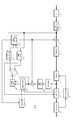
도 1은 화상 부호화 장치의 구성을 도시하는 도면이다.
도 2는 디블록킹 필터의 필터 처리에 사용하는 화소 데이터를 도시한 도면이다.
도 3은 양자화 파라미터(QP)와 임계값(α)의 관계를 나타내는 도면이다.
도 4는 디블록킹 필터와 필터 설정부의 구성을 도시하는 도면이다.
도 5는 화상 부호화 처리에서 사용하는 예측 블록 사이즈를 나타내는 도면이다.
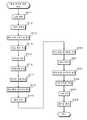
도 6은 화상 부호화 처리 동작을 나타내는 흐름도이다.
도 7은 예측 처리를 나타내는 흐름도이다.
도 8은 인트라 예측 처리를 나타내는 흐름도이다.
도 9는 인터 예측 처리를 나타내는 흐름도이다.
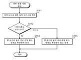
도 10은 필터 설정 처리를 나타내는 흐름도이다.
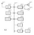
도 11은 화상 복호화 장치의 구성을 도시하고 있다.
도 12는 화상 복호화 처리 동작을 나타내는 흐름도이다.
도 13은 텔레비전 장치의 개략 구성을 예시한 도면이다.
도 14는 휴대 전화기의 개략 구성을 예시한 도면이다.
도 15는 기록 재생 장치의 개략 구성을 예시한 도면이다.
도 16은 촬상 장치의 개략 구성을 예시한 도면이다.1 is a diagram illustrating a configuration of a picture coding apparatus.
2 is a diagram illustrating pixel data used for filter processing of a deblocking filter.
3 is a diagram illustrating a relationship between the quantization parameter QP and the threshold value α.
4 is a diagram illustrating a configuration of a deblocking filter and a filter setting unit.
5 is a diagram illustrating a predicted block size used in the image encoding process.
6 is a flowchart showing an image encoding processing operation.
7 is a flowchart showing a prediction process.
8 is a flowchart illustrating intra prediction processing.
9 is a flowchart showing inter prediction processing.
10 is a flowchart showing filter setting processing.
11 shows the configuration of a picture decoding apparatus.
12 is a flowchart showing an image decoding processing operation.
13 is a diagram illustrating a schematic configuration of a television device.
14 is a diagram illustrating a schematic configuration of a mobile phone.
15 is a diagram illustrating a schematic configuration of a recording and reproducing apparatus.
16 is a diagram illustrating a schematic configuration of an imaging device.
이하, 본 기술을 실시하기 위한 형태에 대해서 설명한다. 본 기술의 화상 처리 장치는, 예측 블록 사이즈로 화상 데이터를 부호화 처리하는 화상 부호화 장치나, 예측 블록 사이즈로 부호화가 행해진 화상 데이터를 복호화 처리하는 화상 복호화 장치 등에 적용 가능하다. 따라서, 화상 부호화 장치에 적용한 경우와 화상 복호화 장치에 적용한 경우에 대해서 이하의 순서로 설명한다.EMBODIMENT OF THE INVENTION Hereinafter, the form for implementing this technology is demonstrated. The image processing apparatus of the present technology can be applied to an image coding apparatus for encoding image data at a predictive block size, an image decoding apparatus for decoding the image data subjected to encoding at a predictive block size, and the like. Therefore, the case where it applies to the image coding apparatus, and the case where it is applied to the image decoding apparatus is demonstrated in the following procedure.
1. 화상 부호화 장치의 구성1. Configuration of the picture coding apparatus
2. 디블록킹 필터의 필터 처리에 대해서2. Filtering of Deblocking Filter
3. 화상 부호화 장치에 있어서의 디블록킹 필터의 구성3. Structure of deblocking filter in picture coding apparatus
4. 화상 부호화 장치의 동작4. Operation of the picture coding apparatus
5. 화상 복호화 장치의 구성5. Configuration of the picture decoding apparatus
6. 화상 복호화 장치의 동작6. Operation of the picture decoding apparatus
7. 응용예7. Application
<1. 화상 부호화 장치의 구성><1. Structure of Image Coding Device>
도 1은 화상 부호화 장치의 구성을 도시하고 있다. 화상 부호화 장치(10)는 아날로그/디지털 변환부(A/D 변환부)(11), 화면 재배열 버퍼(12), 감산부(13), 직교 변환부(14), 양자화부(15), 가역 부호화부(16), 축적 버퍼(17), 레이트 제어부(18)를 구비하고 있다. 또한, 화상 부호화 장치(10)는 역양자화부(21), 역직교 변환부(22), 가산부(23), 디블록킹 필터(24), 프레임 메모리(25), 셀렉터(26), 인트라 예측부(31), 움직임 예측·보상부(32), 예측 화상·최적 모드 선택부(33)를 구비하고 있다.1 shows the configuration of a picture coding apparatus. The
A/D 변환부(11)는 아날로그의 화상 신호를 디지털의 화상 데이터로 변환해서 화면 재배열 버퍼(12)에 출력한다.The A / D converter 11 converts analog image signals into digital image data and outputs them to the
화면 재배열 버퍼(12)는 A/D 변환부(11)로부터 출력된 화상 데이터에 대하여 프레임의 재배열을 행한다. 화면 재배열 버퍼(12)는 부호화 처리에 관한 GOP(Group of Pictures) 구조에 따라서 프레임의 재배열을 행하고, 재배열 후의 화상 데이터를 감산부(13)와 인트라 예측부(31)와 움직임 예측·보상부(32)에 출력한다.The
감산부(13)에는 화면 재배열 버퍼(12)로부터 출력된 화상 데이터와, 후술하는 예측 화상·최적 모드 선택부(33)에서 선택된 예측 화상 데이터가 공급된다. 감산부(13)는 화면 재배열 버퍼(12)로부터 출력된 화상 데이터와 예측 화상·최적 모드 선택부(33)로부터 공급된 예측 화상 데이터의 차분인 예측 오차 데이터를 산출하여 직교 변환부(14)에 출력한다.The subtractor 13 is supplied with image data output from the
직교 변환부(14)는 감산부(13)로부터 출력된 예측 오차 데이터에 대하여 이산 코사인 변환(DCT; Discrete Cosine Transform), 카루넨 루베 변환 등의 직교 변환 처리를 행한다. 직교 변환부(14)는 직교 변환 처리를 행함으로써 얻어진 변환 계수 데이터를 양자화부(15)에 출력한다.The
양자화부(15)에는 직교 변환부(14)로부터 출력된 변환 계수 데이터와, 후술하는 레이트 제어부(18)로부터 레이트 제어 신호가 공급되고 있다. 양자화부(15)는 변환 계수 데이터의 양자화를 행하고, 양자화 데이터를 가역 부호화부(16)와 역양자화부(21)에 출력한다. 또한, 양자화부(15)는 레이트 제어부(18)로부터의 레이트 제어 신호에 기초하여 양자화 파라미터(양자화 스케일)를 전환하여 양자화 데이터의 비트 레이트를 변화시킨다.The
가역 부호화부(16)에는 양자화부(15)로부터 출력된 양자화 데이터와, 후술하는 인트라 예측부(31)와 움직임 예측·보상부(32) 및 예측 화상·최적 모드 선택부(33)로부터 예측 모드 정보가 공급된다. 또한, 예측 모드 정보에는 인트라 예측 또는 인터 예측에 따라서 예측 블록 사이즈를 식별 가능하게 하는 매크로 블록 타입, 예측 모드, 움직임 벡터 정보, 참조 픽쳐 정보 등이 포함된다. 가역 부호화부(16)는 양자화 데이터에 대하여 예를 들어 가변장부호화, 또는 산술부호화 등에 의해 가역 부호화 처리를 행하고, 부호화 스트림을 생성해서 축적 버퍼(17)에 출력한다. 또한, 가역 부호화부(16)는 예측 모드 정보를 가역 부호화하여 부호화 스트림의 헤더 정보에 부가한다.The
축적 버퍼(17)는 가역 부호화부(16)로부터의 부호화 스트림을 축적한다. 또한, 축적 버퍼(17)는 축적한 부호화 스트림을 전송로에 따른 전송 속도로 출력한다.The
레이트 제어부(18)는 축적 버퍼(17)의 빈 용량의 감시를 행하고, 빈 용량에 따라서 레이트 제어 신호를 생성해서 양자화부(15)에 출력한다. 레이트 제어부(18)는, 예를 들어 축적 버퍼(17)로부터 빈 용량을 나타내는 정보를 취득한다. 레이트 제어부(18)는 빈 용량이 적어졌을 때, 레이트 제어 신호에 의해 양자화 데이터의 비트 레이트를 저하시킨다. 또한, 레이트 제어부(18)는 축적 버퍼(17)의 빈 용량이 충분히 클 때, 레이트 제어 신호에 의해 양자화 데이터의 비트 레이트를 높게 한다.The rate control unit 18 monitors the storage capacity of the
역양자화부(21)는 양자화부(15)로부터 공급된 양자화 데이터의 역양자화 처리를 행한다. 역양자화부(21)는 역양자화 처리를 행함으로써 얻어진 변환 계수 데이터를 역직교 변환부(22)에 출력한다.The inverse quantization unit 21 performs inverse quantization processing of quantized data supplied from the
역직교 변환부(22)는 역양자화부(21)로부터 공급된 변환 계수 데이터의 역직교 변환 처리를 행함으로써 얻어진 데이터를 가산부(23)에 출력한다.The inverse
가산부(23)는 역직교 변환부(22)로부터 공급된 데이터와 예측 화상·최적 모드 선택부(33)로부터 공급된 예측 화상 데이터를 가산해서 복호 화상 데이터를 생성하여 디블록킹 필터(24)와 프레임 메모리(25)에 출력한다.The
디블록킹 필터(24)는 화상의 부호화 시에 발생하는 블록 변형을 감소시키기 위한 필터 처리를 행한다. 디블록킹 필터(24)는 가산부(23)로부터 공급된 복호 화상 데이터로부터 블록 변형을 제거하는 필터 처리를 행하고, 필터 처리 후의 복호 화상 데이터를 프레임 메모리(25)에 출력한다. 또한, 디블록킹 필터(24)는 후술하는 필터 설정부(41)로부터 공급된 파라미터값에 기초하여 탭 길이와 필터 처리 대상 화소 범위를 설정한다.The
프레임 메모리(25)는 가산부(23)로부터 공급된 복호 화상 데이터와 디블록킹 필터(24)로부터 공급된 필터 처리 후의 복호 화상 데이터를 보유 지지한다.The
셀렉터(26)는 인트라 예측을 행하기 위해서 프레임 메모리(25)로부터 판독된 필터 처리 전의 복호 화상 데이터를 인트라 예측부(31)에 공급한다. 또한, 셀렉터(26)는 인터 예측을 행하기 위해서 프레임 메모리(25)로부터 판독된 필터 처리 후의 복호 화상 데이터를 움직임 예측·보상부(32)에 공급한다.The selector 26 supplies the decoded image data before the filter process read out from the
인트라 예측부(31)는 화면 재배열 버퍼(12)로부터 출력된 부호화 대상 화상의 화상 데이터와 프레임 메모리(25)로부터 판독한 필터 처리 전의 복호 화상 데이터를 사용하여 후보가 되는 모든 인트라 예측 모드의 인트라 예측 처리를 행한다. 또한, 인트라 예측부(31)는 각 인트라 예측 모드에 대하여 비용 함수값을 산출하여 산출한 비용 함수값이 최소가 되는 인트라 예측 모드, 즉 부호화 효율이 가장 양호해지는 인트라 예측 모드를 최적 인트라 예측 모드로서 선택한다. 인트라 예측부(31)는 최적 인트라 예측 모드에서 생성된 예측 화상 데이터와 최적 인트라 예측 모드에 관한 예측 모드 정보 및 최적 인트라 예측 모드에서의 비용 함수값을 예측 화상·최적 모드 선택부(33)에 출력한다. 또한, 인트라 예측부(31)는 후술하는 바와 같이 비용 함수값의 산출에서 사용하는 발생 부호량을 얻기 위해서, 각 인트라 예측 모드의 인트라 예측 처리에 있어서, 인트라 예측 모드에 관한 예측 모드 정보를 가역 부호화부(16)에 출력한다.The intra prediction unit 31 uses all the intra prediction modes as candidates using the image data of the encoding target image output from the
움직임 예측·보상부(32)는 매크로 블록에 대응하는 모든 예측 블록 사이즈로 움직임 예측·보상 처리를 행한다. 움직임 예측·보상부(32)는 화면 재배열 버퍼(12)로부터 판독된 부호화 대상 화상에 있어서의 각 예측 블록 사이즈의 화상마다 프레임 메모리(25)로부터 판독된 필터 처리 후의 복호 화상 데이터를 사용해서 움직임 벡터를 검출한다. 또한, 움직임 예측·보상부(32)는 검출한 움직임 벡터에 기초하여 복호 화상에 움직임 보상 처리를 실시해서 예측 화상의 생성을 행한다. 또한, 움직임 예측·보상부(32)는 각 예측 블록 사이즈에 대하여 비용 함수값을 산출하여 산출한 비용 함수값이 최소가 되는 예측 블록 사이즈, 즉 부호화 효율이 가장 양호해지는 예측 블록 사이즈를 최적 인터 예측 모드로서 선택한다. 움직임 예측·보상부(32)는 최적 인터 예측 모드에서 생성된 예측 화상 데이터와 최적 인터 예측 모드에 관한 예측 모드 정보 및 최적 인터 예측 모드에서의 비용 함수값을 예측 화상·최적 모드 선택부(33)에 출력한다. 또한, 움직임 예측·보상부(32)는 비용 함수값의 산출에서 사용하는 발생 부호량을 얻기 위해서, 각 예측 블록 사이즈에서의 인터 예측 처리에 있어서, 인터 예측 모드에 관한 예측 모드 정보를 가역 부호화부(16)에 출력한다. 또한, 움직임 예측·보상부(32)는 인터 예측 모드로서 스킵드 매크로 블록이나 다이렉트 모드에서의 예측도 행한다.The motion prediction / compensation unit 32 performs motion prediction / compensation processing at all prediction block sizes corresponding to the macroblocks. The motion prediction / compensation unit 32 uses the decoded image data after the filter processing read out from the
예측 화상·최적 모드 선택부(33)는 인트라 예측부(31)로부터 공급된 비용 함수값과 움직임 예측·보상부(32)로부터 공급된 비용 함수값을, 매크로 블록 단위로 비교해서 비용 함수값이 적은 쪽을 부호화 효율이 가장 양호해지는 최적 모드로서 선택한다. 또한, 예측 화상·최적 모드 선택부(33)는 최적 모드에서 생성한 예측 화상 데이터를 감산부(13)와 가산부(23)에 출력한다. 또한, 예측 화상·최적 모드 선택부(33)는 최적 모드의 예측 모드 정보를 가역 부호화부(16)와 필터 설정부(41)에 출력한다. 또한, 예측 화상·최적 모드 선택부(33)는 슬라이스 단위로 인트라 예측 또는 인터 예측을 행한다.The predictive image / optimal mode selection unit 33 compares the cost function value supplied from the intra prediction unit 31 with the cost function value supplied from the motion prediction / compensation unit 32 in units of macroblocks, and the cost function value is determined. The smaller one is selected as the optimum mode with the best coding efficiency. The predictive image / optimal mode selection unit 33 also outputs the predictive image data generated in the optimum mode to the subtractor 13 and the
필터 설정부(41)는 최적 모드의 예측 모드 정보에 의해 나타내진 예측 블록 사이즈에 따라서 필터의 탭 길이와 필터 처리 대상 화소 범위를 설정하기 위한 파라미터값을 생성해서 디블록킹 필터(24)에 출력한다.The
<2. 디블록킹 필터의 필터 처리에 대해서><2. About Filtering of Deblocking Filters>
디블록킹 필터의 필터 처리에 있어서, H264./AVC의 부호화 방식에서는 화상 압축 정보에 포함되는 Picture Parameter Set RBSP의 deblocking_filter_control_present_flag 및 Slice Header에 포함되는 disable_deblocking_filter_idc이라는 2개의 파라미터에 의해,In the filter processing of the deblocking filter, in the H264./AVC coding scheme, two parameters, deblocking_filter_control_present_flag of the Picture Parameter Set RBSP included in the image compression information and disable_deblocking_filter_idc included in the Slice Header,
(a)블록 경계 및 매크로 블록 경계에 실시한다.(a) The block boundary and the macro block boundary are implemented.
(b)매크로 블록 경계에만 실시한다.(b) Only at macroblock boundaries.
(c)실시하지 않는다.(c) No.
의 3가지를 지정하는 것이 가능하다.It is possible to specify three things.
양자화 파라미터(QP)에 대해서는, 이하의 처리를 휘도 데이터에 대하여 적용할 경우에는 QPY를, 색차 데이터에 대하여 적용할 경우에는 QPC를 사용한다. 또한, 움직임 벡터 부호화, 인트라 예측, 엔트로피 부호화(CAVLC/CABAC)에 있어서는, 상이한 슬라이스에 속하는 화소값은 “not available”로서 처리한다. 또한, 필터 처리에 있어서는, 상이한 슬라이스에 속하는 화소값이라도 동일한 픽쳐에 속하는 경우에는 “available”이라고 하여 처리를 행한다.As for the quantization parameter QP, QPY is used when the following processing is applied to the luminance data, and QPC is used when the color difference data is applied. In motion vector coding, intra prediction, and entropy coding (CAVLC / CABAC), pixel values belonging to different slices are processed as "not available". In the filter process, even if pixel values belonging to different slices belong to the same picture, processing is performed as "available".
이하의 설명에서는, 인접하는 블록(P, Q)에 대해서, 블록 경계에 있어서의 필터 처리 전의 화소 데이터를 도 2의 (A)에 도시한 바와 같이 경계 위치로부터 p0 내지 p4, q0 내지 q4로 한다. 또한, 처리 후의 화소 데이터를 도 2의 (B)에 도시한 바와 같이 경계 위치로부터 p0' 내지 p4',q0' 내지 q4'로 한다.In the following description, the pixel data before the filter process in a block boundary is made p0-p4, q0-q4 from the boundary position with respect to the adjacent block P and Q as shown to FIG. . Further, the pixel data after the processing is set to p0 'to p4', q0 'to q4' from the boundary position as shown in Fig. 2B.
필터 처리에 앞서, 도 2에 있어서의 화소(p) 및 화소(q)에 대하여, 표 1에 나타낸 바와 같이, 블록 경계 강도 데이터(Bs)(Boundary Strength)가 정의된다.Prior to the filter processing, as shown in Table 1, block boundary strength data Bs (Boundary Strength) is defined for the pixels p and the pixels q in FIG.
(Strongest Filtering)Bs = 4
(Strongest Filtering)
(No Filtering)Bs = 0
(No Filtering)
표 1에 나타낸 바와 같이, 블록 경계 강도 데이터(Bs)는 화소(p) 또는 화소(q) 중 어느 한쪽이 인트라 부호화되는 매크로 블록(MB)에 속하고, 또한 해당 화소가 매크로 블록(MB)의 경계에 위치하는 경우에 가장 필터 강도가 높은 「4」가 할당되어 있다.As shown in Table 1, the block boundary intensity data Bs belongs to the macro block MB in which either the pixel p or the pixel q is intra-coded, and the pixel is the macroblock MB. In the case where it is located at the boundary, "4" having the highest filter strength is assigned.
블록 경계 강도 데이터(Bs)는 화소(p) 또는 화소(q) 중 어느 한쪽이 인트라 부호화되는 매크로 블록(MB)에 속하고, 또한 해당 화소가 매크로 블록(MB)의 경계에 위치하지 않는 경우에 「4」 다음에 필터 강도가 높은 「3」이 할당되어 있다.The block boundary intensity data Bs belongs to the macro block MB in which either the pixel p or the pixel q is intra coded, and the pixel is not located at the boundary of the macro block MB. After "4", "3" with high filter intensity is assigned.
블록 경계 강도 데이터(Bs)는 화소(p) 및 화소(q)의 양쪽이 인트라 부호화되는 매크로 블록(MB)에 속하는 것이 아니고, 또한 어느 쪽 화소가 변환 계수를 가질 경우에 「3」 다음으로 필터 강도가 높은 「2」가 할당되어 있다.The block boundary intensity data Bs does not belong to the macro block MB in which both the pixel p and the pixel q are intra coded, and when either pixel has a transform coefficient, the filter is next to "3". "2" with high intensity is assigned.
블록 경계 강도 데이터(Bs)는 화소(p) 및 화소(q)의 양쪽이 인트라 부호화되는 매크로 블록(MB)에 속하는 것이 아니고, 또한 어느 쪽 화소가 변환 계수를 갖지 않는다는 조건인 경우에 만족하고, 또한 참조 프레임이 상이하거나, 참조 프레임의 매수가 상이하거나, 움직임 벡터가 상이하거나 중 어느 쪽 조건을 만족하는 경우에 「1」이 할당되어 있다.The block boundary intensity data Bs is satisfied when both the pixel p and the pixel q do not belong to the macroblock MB to be intra coded, and on the condition that either pixel does not have a transform coefficient, Further, "1" is allocated when the reference frame is different, the number of reference frames is different, or the motion vector is different, or when any of the conditions is satisfied.
블록 경계 강도 데이터(Bs)는 화소(p, q)의 양쪽이 인트라 부호화되는 매크로 블록(MB)에 속하는 것이 아니고, 어느 쪽 화소도 변환 계수를 갖지 않고, 참조 프레임 및 움직임 벡터가 동일한 경우 「0」이 할당되어 있다. 또한, 「0」은 필터 처리를 행하지 않는 것을 의미한다.The block boundary intensity data Bs does not belong to the macro block MB in which both of the pixels p and q are intra coded, and neither pixel has a transform coefficient, and if the reference frame and the motion vector are the same, "0". Is allocated. In addition, "0" means not performing a filter process.
도 2에 있어서의 (p2, p1, p0, q0, q1, q2)는 식(1)의 조건이 성립하는 경우에만 필터 처리가 실시된다.In (p2, p1, p0, q0, q1, q2) in FIG. 2, the filter process is performed only when the condition of Formula (1) is satisfied.
Bs>0Bs> 0
|p0-q0|<α;|p1-p0|<β;|q1-q0|<β ···(1)| p0-q0 | <α; | p1-p0 | <β; | q1-q0 | <β
여기서, 필터 강도 즉 필터의 걸러지기 쉬운 정도를 조정하는 파라미터값인 임계값(α, β)은 디폴트로는 이하와 같이 양자화 파라미터(QP)에 따라서 그 값이 정해져 있다. 또한, 화상 압축 정보 중의 Slice Header에 포함되는 slice_alpha_c0_offset_div2 및 slice_beta_offset_div2이라는 2개의 파라미터에 의해 사용자가 그 강도를 조정하는 것이 가능하다. 또한, 도 3은 양자화 파라미터(QP)와 임계값(α)의 관계를 나타내고 있고, 양자화 파라미터(QP)에 오프셋량을 가하면, 양자화 파라미터(QP)와 임계값(α)의 관계를 나타내는 곡선은 화살표 방향으로 이동하는 점에서 필터 강도를 조정하는 것이 명백하다.Here, the threshold values α and β, which are parameter values for adjusting the filter strength, that is, the filterability of the filter, are basically determined according to the quantization parameter QP as follows. Further, the user can adjust the intensity by two parameters, slice_alpha_c0_offset_div2 and slice_beta_offset_div2, included in the Slice Header in the image compression information. 3 shows the relationship between the quantization parameter QP and the threshold value α. When an offset amount is added to the quantization parameter QP, a curve showing the relationship between the quantization parameter QP and the threshold value α is obtained. It is evident to adjust the filter strength in terms of moving in the direction of the arrow.
또한, 인접하는 블록(P)과 블록(Q)의 각각의 양자화 파라미터(qPp, qPq)를 사용해서 식 (2) 내지 (4)로부터 indexA와 indexB를 산출하여 표 2에 나타내는 테이블로부터 임계값(α, β)을 구한다.Further, indexA and indexB are calculated from the equations (2) to (4) using the respective quantization parameters qPp and qPq of the adjacent block P and the block Q, and the threshold value ( α, β) are obtained.
qPav=(qPp+qPq+1)>> 1 ···(2) qPav = (qPp + qPq + 1) >> 1 ... (2)
indexA=Clip3 (0, 51, qPav+FilterOffsetA) ···(3) indexA = Clip3 (0, 51, qPav + FilterOffsetA) ... (3)
indexB=Clip3 (0, 51, qPav+FilterOffsetB) ···(4) indexB = Clip3 (0, 51, qPav + FilterOffsetB) ... (4)

필터 처리는 「Bs<4」인 경우와 「Bs=4」인 경우에 대하여 상이한 방법이 정의되어 있다.Different methods are defined for the filter process in the case of "Bs <4" and "Bs = 4".
우선, 「Bs<4」인 경우를 설명한다.First, the case of "Bs <4" is demonstrated.
디블록킹 필터는 식 (5) 내지 (7)에 나타내는 연산을 행하여 필터 처리 후의 화소 데이터 p0',q0'를 산출한다.The deblocking filter performs the operation shown in equations (5) to (7) to calculate the pixel data p0 'and q0' after the filter processing.
식(7)에 있어서, Clip3은 클리핑 처리를 나타낸다.In equation (7), Clip3 represents a clipping process.
p0'=Clip1(p0+Δ) ···(5) p0 '= Clip1 (p0 + Δ) ... (5)
q0'=Clip1(q0+Δ) ···(6) q0 '= Clip1 (q0 + Δ) (6)
Δ=Clip3(-tc, tc ((((q0-p0)<<2)+(p1-q1)+4)>>3)) ···(7) Δ = Clip3 (-tc, tc ((((q0-p0) << 2) + (p1-q1) +4) >> 3)) ... (7)
디블록킹 필터는 식(7)의 「tc」를 chromaEdgeFlag가 「0」을 나타내는 경우에 식(8)에 기초하여 산출하고, 그 이외의 경우에 식(9)에 기초하여 산출한다.The deblocking filter calculates "tc" in formula (7) based on formula (8) when chromaEdgeFlag represents "0", and calculates it based on formula (9) in other cases.
식(8)에 있어서 「( )?1:0」은 ( ) 내의 조건을 만족하면 「1」, 그 이외의 경우에는 「0」을 나타낸다.In formula (8), "()? 1: 0" represents "1" when the conditions in () are satisfied, and "0" in other cases.
tc=tc0+((ap<β)?1:0)+(aq<β)?1:0) ···(8) tc = tc0 + ((ap <β)? 1: 0) + (aq <β)? 1: 0)
tc=tc0+1 ···(9) tc = tc0 + 1 (9)
이 tc의 값은 Bs와 indexA의 값에 따라서 표 3과 같이 정의된다.The value of tc is defined as shown in Table 3 according to the values of Bs and indexA.

또한, 디블록킹 필터는 식(8)의 ap, aq를 식(10), (11)에 따라서 산출한다.The deblocking filter also calculates ap and aq of equation (8) according to equations (10) and (11).
ap=|p2-p0| ···(10) ap = | p2-p0 | (10)
aq=|q2-q0| ···(11) aq = | q2-q0 | (11)
디블록킹 필터는 필터 처리 후의 화소 데이터 p1'를 chromaEdgeFlag가 「0」이고, 또한 ap가 「β」 이하인 경우에 식(12)에 나타내는 연산을 행해서 산출하고, 그 이외의 경우에 식(13)에 의해 취득한다.The deblocking filter calculates the pixel data p1 'after the filter process by performing the operation shown in formula (12) when chromaEdgeFlag is "0" and ap is "β" or less, and otherwise, Acquire by
p1'=p1+Clip3(-tc0, tc0, (p2+((p0+q0+1)>>1)-(p1<<1))>>1) ···(12) p1 '= p1 + Clip3 (-tc0, tc0, (p2 + ((p0 + q0 + 1) >> 1)-(p1 << 1)) >> 1) ... (12)
p1'=p1 ···(13) p1 '= p1 (13)
디블록킹 필터는 필터 처리 후의 화소 데이터 q1'를 chromaEdgeFlag가 「0」이고, 또한 aq가 「β」 이하인 경우에 식(14)에 나타내는 연산을 행해서 산출하고, 그 이외의 경우에 식(15)에 의해 취득한다.The deblocking filter calculates the pixel data q1 'after the filter process by performing the operation shown in equation (14) when chromaEdgeFlag is "0" and aq is "β" or less, and otherwise, Acquire by
q1'=q1+Clip3(-tc0, tc0, (q2+((p0+q0+1)>>1)-(q1<<1))>>1) ···(14) q1 '= q1 + Clip3 (-tc0, tc0, (q2 + ((p0 + q0 + 1) >> 1)-(q1 << 1)) >> 1) ... (14)
q1'=q1 ···(15) q1 '= q1 ... (15)
또한, 화소 데이터 p2'와 화소 데이터 q2'는 필터 전의 값으로 한다.In addition, the pixel data p2 'and the pixel data q2' are taken as the value before a filter.
p2'=p2 ···(16) p2 '= p2 (16)
q2'=q2 ···(17) q2 '= q2 ... (17)
다음에 「Bs=4」인 경우를 설명한다.Next, the case where "Bs = 4" will be described.
디블록킹 필터는 chromaEdgeFlag가 「0」을 나타내고, 또한 식(18)의 조건을 만족하는 경우에 화소 데이터 p0',p1',p2'를 식 (19) 내지 (21)에 따라서 산출한다.The deblocking filter calculates the pixel data p0 ', p1', p2 'according to equations (19) to (21) when chromaEdgeFlag represents "0" and satisfies the condition of equation (18).
ap<β&&|p0-q0|<((α>>2)+2) ···(18) ap <β && | p0-q0 | <((α >> 2) +2) ... (18)
p0'=(p2+2·p1+2·p0+2·q0+q1+4)>> 3 ···(19) p0 '= (p2 + 2p1 + 2p0 + 2q0 + q1 + 4) >> 3 (19)
p1'=(p2+p1+p0+q0+2)>> 2 ···(20) p1 '= (p2 + p1 + p0 + q0 + 2) >> 2 ... (20)
p2'=(2·p3+3·p2+p1+p0+q0+4)>> 3 ···(21) p2 '= (2p3 + 3p2 + p1 + p0 + q0 + 4) >> 3 (21)
디블록킹 필터는 chromaEdgeFlag가 「0」을 나타내고, 또한 식(18)의 조건을 만족하지 않는 경우에 화소 데이터 p0',p1',p2'를 식 (22) 내지 (24)에 따라서 산출한다.The deblocking filter calculates the pixel data p0 ', p1', p2 'according to equations (22) to (24) when chromaEdgeFlag indicates "0" and does not satisfy the condition of Expression (18).
p0'=(2·p1+p0+q1+2)>>2 ···(22) p0 '= (2p1 + p0 + q1 + 2) >> 2 (22)
p1'=p1 ···(23) p1 '= p1 (23)
p2'=p2 ···(24) p2 '= p2 (24)
디블록킹 필터는 chromaEdgeFlag가 「0」을 나타내고, 또한 식(25)의 조건을 만족하는 경우에 화소 데이터 q0',q1',q2'를 식 (26) 내지 (28)에 따라서 산출한다.The deblocking filter calculates pixel data q0 ', q1', q2 'according to equations (26) to (28) when chromaEdgeFlag indicates "0" and satisfies the condition of Expression (25).
aq<β&&|p0-q0|<((α>>2)+2) ···(25) aq <β && | p0-q0 | <((α >> 2) +2) ... (25)
q0'=(p1+2·p0+2·q0+2·q1+q2+4)>> 3 ···(26) q0 '= (
q1'=(p0+q0+q1+q2+2)>> 2 ···(27) q1 '= (p0 + q0 + q1 + q2 + 2) >> 2 ... (27)
q2'=(2·q3+3·q2+q1+q0+p4+4)>> 3 ···(28) q2 '= (2 q3 + 3 q2 + q1 + q0 + p4 + 4) >> 3 (28)
디블록킹 필터는 chromaEdgeFlag가 「0」을 나타내고, 또한 식(25)의 조건을 만족하지 않는 경우에 화소 데이터 q0',q1',q2'를 식 (29) 내지 (31)에 따라서 산출한다.The deblocking filter calculates pixel data q0 ', q1', q2 'according to equations (29) to (31) when chromaEdgeFlag indicates "0" and does not satisfy the condition of Expression (25).
q0'=(2·q1+q0+p1+2)>> 2 ···(29) q0 '= (2 q1 + q0 + p1 + 2) >> 2 ... (29)
q1'=q1 ···(30) q1 '= q1 (30)
q2'=q2 ···(31) q2 '= q2 (31)
이와 같이, H264./AVC의 부호화 방식에서는, 화소 데이터 p0 내지 p3, q0 내지 q3을 이용해서 필터 처리를 행하여 화소 데이터 p0'∼p2',q0'∼q2'를 산출한다.In this manner, in the H264./AVC coding scheme, the filter processing is performed using the pixel data p0 to p3 and q0 to q3 to calculate the pixel data p0 'to p2' and q0 'to q2'.
<3. 화상 부호화 장치에 있어서의 디블록킹 필터와 필터 설정부의 구성><3. Configuration of Deblocking Filter and Filter Setting Unit in Image Coding Device>
필터 설정부(41)는 해당 매크로 블록에 있어서의 최적 모드의 예측 블록 사이즈에 따라서 디블록킹 필터(24)에 있어서의 탭 길이와 필터 처리 대상 화소 범위를 설정한다.The
일반적으로, 블록 변형은 블록 사이즈가 보다 큰 경우가 사람 눈에 띄기 쉽다. 또한, 보다 큰 블록 사이즈는 그다지 텍스쳐 정보를 포함하지 않는 편평한 영역에 대하여 선택되기 쉽다.In general, block deformation is more noticeable when the block size is larger. Also, larger block sizes are likely to be chosen for flat areas that do not contain much texture information.
따라서, 필터 설정부(41)는 인접하는 2개의 블록에 있어서의 인접측의 블록 사이즈에 따라서 케이스 분류를 행하고, 케이스 분류 결과에 따라서 필터 처리의 탭 길이와 필터 처리 대상 화소 범위를 설정한다. 필터 설정부(41)는, 케이스 분류에 있어서, 예를 들어 인접하는 2개의 블록에 있어서의 인접측이 모두 소정 블록 사이즈 이하의 케이스와, 적어도 한쪽이 소정의 블록 사이즈보다 확장되어 있는 케이스로 분류한다.Accordingly, the
필터 설정부(41)는 인접하는 2개의 블록에 있어서의 인접측의 블록 사이즈가 모두 소정 블록 사이즈 이하, 예를 들어 H.264/AVC 규격의 매크로 블록 사이즈인 케이스에서는, 상술한 바와 같이 필터 처리를 행하여 화소 데이터 p0'∼p2',q0'∼q2'를 산출한다. 또한, 필터 설정부(41)는 적어도 한쪽이 소정의 블록 사이즈보다 확장되어 있는 경우, 블록 경계의 블록 사이즈에 따라서 탭 길이나 필터 처리 대상 화소 범위의 확장을 행한다. 필터 설정부(41)는 탭 길이나 필터 처리 대상 화소 범위를 확장함으로써, 블록 사이즈가 크게 블록 변형이 눈에 띄기 쉬운 부분에 대해서는, 보다 강도가 강한 평활화 처리나 블록 경계에 대하여 보다 먼 화소값까지 필터 처리를 실시한다. 따라서, 블록 변형이 눈에 띄기 어려워져서 복호 화상에 있어서의 주관 화질을 보다 바람직한 것으로 한다.In the case where the adjacent block sizes in the two adjacent blocks are all smaller than or equal to a predetermined block size, for example, the macro block size of the H.264 / AVC standard, the
또한, 보다 강도가 강한 평활화 처리를 행하면, 화상이 갖는 고영역 성분도 상실된다. 그러나, 큰 블록 사이즈가 적용되는 것은 화상 내에 있어서 고영역 성분이 적은 비교적 편평한 영역인 경우가 많으므로, 텍스쳐가 상실된다는 주관상의 열화를 발생시키는 경우는 없다.In addition, when the smoothing process having a stronger intensity is performed, the high region component of the image is also lost. However, since a large block size is often applied to a relatively flat area with few high area components in the image, no subjective deterioration of texture loss occurs.
이와 같이, 필터 설정부(41)는 예측 블록 사이즈에 따라서 설정한 탭 길이와 필터 처리 대상 화소 범위를 나타내는 파라미터값을 생성해서 디블록킹 필터(24)에 공급한다. 또한, 필터 설정부(41)는 소정의 매크로 블록보다도 블록 사이즈가 큰 복수의 상이한 사이즈의 매크로 블록이 사용되는 경우, 블록 사이즈가 클수록 탭 길이가 길고 필터 처리 대상 화소 범위가 넓어지도록 설정해도 된다.In this way, the
도 4는 디블록킹 필터와 필터 설정부의 구성을 도시하고 있다. 필터 설정부(41)는 블록 사이즈 버퍼(411)와 파라미터값 생성부(412)를 구비하고 있다. 또한, 디블록킹 필터(24)는 필터 강도 결정부(241)와 필터 처리부(242)를 구비하고 있다.4 illustrates the configuration of the deblocking filter and the filter setting unit. The
블록 사이즈 버퍼(411)는 예측 화상·최적 모드 선택부(33)에서 선택된 최적 모드 있어서의 예측 블록 사이즈를 나타내는 정보를 1프레임 화상만큼 축적한다. 즉, 블록 사이즈 버퍼(411)에는 부호화 대상의 1프레임 화상에 있어서의 각 매크로 블록의 예측 블록 사이즈에 관한 정보가 기억되어 있는 상태가 된다.The block size buffer 411 accumulates information indicating the predicted block size in the optimum mode selected by the predictive picture / optimal mode selection unit 33 by one frame image. That is, the block size buffer 411 is in a state in which information about the predicted block size of each macro block in one frame image to be encoded is stored.
파라미터값 생성부(412)는 블록 사이즈 버퍼(411)의 예측 블록 사이즈의 정보에 기초하여, 인접하는 2개의 블록에 있어서의 인접측의 예측 블록 사이즈를 판별한다. 파라미터값 생성부(412)는 이 2개의 블록의 블록 경계에 대한 필터 처리의 탭 길이와 필터 처리 대상 화소 범위를 설정하기 위한 파라미터값을, 판별한 예측 블록 사이즈에 기초하여 생성해서 필터 강도 결정부(241)에 공급한다.The parameter value generation unit 412 determines the prediction block size of the adjacent side in two adjacent blocks based on the information of the prediction block size of the block size buffer 411. The parameter value generator 412 generates a parameter value for setting the tap length of the filter process for the block boundary of these two blocks and the filter target pixel range based on the determined predicted block size, and then the filter intensity determiner. It supplies to 241.
필터 강도 결정부(241)는 가역 부호화부(16)로부터 공급된 예측 모드 정보 에 기초하여 블록 경계 강도 데이터(Bs)를 결정하여 결정한 블록 경계 강도 데이터(Bs)와 파라미터값 생성부(412)로부터 공급된 파라미터값을 필터 처리부(242)에 출력한다.The filter strength determiner 241 determines the block boundary strength data Bs based on the prediction mode information supplied from the
필터 처리부(242)는 블록 경계 강도 데이터(Bs)와 파라미터값으로 나타내어진 탭 길이와 필터 처리 대상 화소 범위에서 필터 처리를 행하여 필터 처리 후의 화소 데이터를 산출한다.The
여기서, 인접하는 2개의 블록에 있어서의 인접측의 예측 블록 사이즈가 모두 소정 블록 사이즈(16×16화소) 이하인 제1 케이스와, 적어도 한쪽이 소정 블록 사이즈보다도 확장되어 있는 제2 케이스로 케이스 분류하는 경우에 대해서 예시한다. 이 경우, 제1 케이스에서는 상술한 H.264/AVC의 부호화 방식의 필터 처리를 행한다. 또한, 제2 케이스에서는 탭 길이를 확장한 길이로 설정해서 평활화의 강도를 강하게 한다. 및/또는, 필터 처리 대상 화소 범위를 확장하여 블록 경계로부터 이격된 위치의 화소까지 필터 처리를 행한다.Here, the case is classified into a first case in which the adjacent prediction block sizes in two adjacent blocks are all smaller than or equal to a predetermined block size (16x16 pixels), and a second case in which at least one is larger than the predetermined block size. The case is illustrated. In this case, in the first case, the above-described H.264 / AVC coding method filter processing is performed. In addition, in the second case, the tab length is set to the extended length to increase the strength of the smoothing. And / or filter processing is performed up to the pixel at a position spaced apart from the block boundary by extending the filter processing target pixel range.
다음에, 탭 길이와 필터 처리 대상 화소 범위를 확장했을 때의 필터 처리에 대해서 예시한다.Next, filter processing when the tap length and the filter processing target pixel range are expanded will be described.
필터 처리부(242)는 파라미터값에 기초하여 탭 길이와 필터 처리 대상 화소 범위를 확장해서 필터 처리를 행하고, 화소 데이터 p0 내지 p4, q0 내지 q4로부터 필터 처리 후의 화소 데이터 p0'∼p3',q0'∼q3'를 산출한다. 이 경우, 필터 처리부(242)는 상술한 식(7) 대신에 식(32)를 이용한다.The
Δ=Clip3(-tc, tc((((q0-p0)<<3)+((p1-q1)<<1)+(p2-q2)+8)>>4)) Δ = Clip3 (-tc, tc ((((q0-p0) << 3) + ((p1-q1) << 1) + (p2-q2) +8) >> 4))
···(32) (32)
또한, 필터 처리부(242)는 식(12), (14) 대신에 식(33), (34)를 이용함으로써 화소 데이터 p1',q1'를 산출한다.In addition, the
p1'=p1+Clip3(-tc0, tc0, (p3+p2+p0+((q0+q1+1)>>1)-(p1<<2))>>2) p1 '= p1 + Clip3 (-tc0, tc0, (p3 + p2 + p0 + ((q0 + q1 + 1) >> 1)-(p1 << 2)) >> 2)
···(33) (33)
q1'=q1+Clip3(-tc0, tc0, (q3+q2+q0+((q0+q1+1)>>1)-(q1<<2))>>2) q1 '= q1 + Clip3 (-tc0, tc0, (q3 + q2 + q0 + ((q0 + q1 + 1) >> 1)-(q1 << 2)) >> 2)
···(34) (34)
또한, 필터 처리부(242)는 식(16), (17) 대신에 식(35), (36)을 이용함으로써 화소 데이터 p2',q2'를 산출한다.In addition, the
p2'=p2+Clip3(-tc0,tc0, (p4+p3+p1+((p0+q1+1)>>1)-(p2<<2))>>2) p2 '= p2 + Clip3 (-tc0, tc0, (p4 + p3 + p1 + ((p0 + q1 + 1) >> 1)-(p2 << 2)) >> 2)
··· (35) (35)
q2'=q2+Clip3(-tc0, tc0, (q4+q3+q1+((q0+q1+1)>>1)-(q2<<2))>>2) q2 '= q2 + Clip3 (-tc0, tc0, (q4 + q3 + q1 + ((q0 + q1 + 1) >> 1)-(q2 << 2)) >> 2)
···(36) (36)
또한, 필터 처리부(242)는 chromaEdgeFlag가 「0」을 나타내고, 또한 식(18)의 조건을 만족하는 경우에, 화소 데이터 p0',p1',p2',p3'를 식(37) 내지 (40)에 따라서 산출한다.In addition, the
p0'=p3+2·p2+3·p1+4·p0+3·q0+2·q1+q2+8)>>4 ···(37) p0 '= p3 + 2p2 + 3p1 + 4p0 + 3q0 + 2q1 + q2 + 8) >> 4 (37)
p1'=(p3+p2+2·p1+2·p0+q0+q1+4)>>3 ···(38) p1 '= (p3 + p2 + 2p1 + 2p0 + q0 + q1 + 4) >> 3 (38)
p2'=(p4+3·p3+4·p2+3·p1+2·p0+2·q0+q1+8)>>4 ···(39) p2 '= (p4 + 3p3 + 4p2 + 3p1 + 2p0 + 2q0 + q1 + 8) >> 4 (39)
p3'=(p4+3·p3+p2+p1+p0+q0+4)>>3 ···(40) p3 '= (p4 + 3p3 + p2 + p1 + p0 + q0 + 4) >> 3 (40)
또한, 필터 처리부(242)는 chromaEdgeFlag가 「0」을 나타내고, 또한 식(25)의 조건을 만족하는 경우에, 화소 데이터 q0',q1',q2',q3'를 식(41) 내지 (44)에 따라서 산출한다.In addition, the
q0'=(p2+2·p1+3·p0+4·q0+3·q1+2·q2+q3+8)>>4 ···(41) q0 '= (
q1'=(p1+p0+2·q0+2·q1+q2+q3+4)>>3 ···(42) q1 '= (p1 + p0 + 2 ·
q2'=(q4+3·q3+4·q2+3·q1+2·q0+2·p0+p1+8)>>4 ···(43) q2 '= (q4 + 3q3 + 4q2 + 3q1 + 2q0 + 2p0 + p1 + 8) >> 4 (43)
q3'=(q4+3·q3+q2+q1+q0+p0+4)>>3 ···(44) q3 '= (q4 + 3q3 + q2 + q1 + q0 + p0 + 4) >> 3 (44)
또한, 탭 길이와 필터 처리 대상 화소 범위의 설정은, 2개의 블록이 모두 16×16화소 혹은 그 이하의 크기인 경우와, 2개의 블록의 적어도 한쪽이 16×16화소보다 큰 경우의 2개로 케이스 분류하는 경우에 한정되지 않는다. 예를 들어, 2개의 블록이 모두 16×16화소 혹은 그 이하의 크기인 경우와, 2개의 블록의 적어도 한쪽이 16×16화소보다 크고, 양쪽이 32×32화소 이하인 경우나, 2개의 블록의 적어도 한쪽이 32×32화소보다 큰 경우의 케이스 분류를 행하도록 해도 된다. 이 경우, 블록 사이즈가 보다 큰 경계에서는, 탭 길이를 더욱 길게 해서 평활화의 강도를 강하게, 또 필터 처리 대상 화소 범위를 더욱 넓게 해서 블록 경계로부터 먼 화소값에 대하여 필터 처리를 행하도록 한다. 또한, 탭 길이와 필터 처리 대상 화소 범위의 설정에서는, 케이스 분류 결과에 따라서 탭 길이와 필터 처리 대상 화소 범위 중 어느 한쪽만을 확장하도록 해도 된다.In addition, the setting of the tap length and the filter target pixel range is performed in two cases in which two blocks are both 16x16 pixels or less in size, and at least one of the two blocks is larger than 16x16 pixels. It is not limited to classifying. For example, when two blocks are both 16x16 pixels or less in size, at least one of the two blocks is larger than 16x16 pixels, and both blocks are 32x32 pixels or less. Case sorting may be performed when at least one is larger than 32x32 pixels. In this case, at the boundary where the block size is larger, the tap length is further lengthened, the smoothing intensity is increased, and the filter subject pixel range is further widened, so that the filter processing is performed on pixel values far from the block boundary. In setting the tap length and the filter processing target pixel range, only one of the tap length and the filter processing target pixel range may be extended according to the case classification result.
이와 같이, 화상 부호화 장치에서는, 인접하는 2개의 블록에 있어서의 인접측의 블록 사이즈에 따라서 필터의 탭 길이와 필터 처리 대상 화소 범위를 설정하여, 블록 사이즈가 크게 블록 변형이 눈에 띄기 쉬운 부분에 대해서는, 평활화의 강도를 강하게 하거나, 블록 경계에 대하여 보다 먼 화소값까지 필터 처리를 실시한다. 따라서, 블록 변형이 눈에 띄기 어려워져서, 예측 화상의 생성에 사용하는 복호 화상에 있어서의 화질을 보다 바람직한 것으로 할 수 있다.In this way, in the image coding apparatus, the tap length of the filter and the filter processing target pixel range are set in accordance with the adjacent block size in two adjacent blocks, and the block size is large in a portion where block deformation is prominent. The smoothing intensity is increased, or the filter process is performed to a pixel value farther from the block boundary. Therefore, block deformation becomes less noticeable, and the image quality in the decoded image used for generating the predictive image can be made more preferable.
<4. 화상 부호화 장치의 동작><4. Operation of the Picture Coding Device>
다음에, 화상 부호화 처리 동작에 대해서 설명한다. 도 5는 화상 부호화 처리에서 사용하는 예측 블록 사이즈를 나타내고 있다. H.264/AVC 방식에서는, 도 5의 (C), (D)에 도시한 바와 같이 16×16화소 내지 4×4화소의 예측 블록 사이즈가 규정되어 있다. 또한, H.264/AVC 방식보다도 확장된 크기의 매크로 블록을 사용하는 경우, 예를 들어 32×32화소의 매크로 블록을 사용하는 경우, 예를 들어 도 5의 (B)에 나타내는 예측 블록 사이즈가 규정된다. 또한, 예를 들어 64×64화소의 매크로 블록을 사용하는 경우, 예를 들어 도 5의 (A)에 나타내는 예측 블록 사이즈가 규정된다.Next, the image coding processing operation will be described. 5 shows a predicted block size used in the image coding process. In the H.264 / AVC system, as shown in Figs. 5C and 5D, prediction block sizes of 16x16 pixels to 4x4 pixels are defined. In addition, when using a macroblock of a larger size than the H.264 / AVC method, for example, when using a macroblock of 32x32 pixels, for example, the prediction block size shown in FIG. It is prescribed. For example, when using a macroblock of 64x64 pixels, for example, the prediction block size shown in Fig. 5A is defined.
또한, 도 5에 있어서, 「Skip/direct」는 움직임 예측·보상부(32)에 있어서 스킵드 매크로 블록이나 다이렉트 모드를 선택했을 때의 예측 블록 사이즈인 것을 나타내고 있다. 또한, 「ME」는 움직임 보상 블록 사이즈인 것을 나타내고 있다. 또한, 「P8×8」은 매크로 블록의 사이즈를 작게 한 하위의 계층에서 더욱 분할할 수 있는 것을 나타내고 있다.In addition, in FIG. 5, "Skip / direct" has shown that it is the prediction block size at the time of skipped macroblock or direct mode in the motion prediction / compensation part 32. As shown in FIG. In addition, "ME" has shown that it is a motion compensation block size. In addition, "P8x8" has shown that it can further divide in the lower layer which made the size of a macroblock small.
도 6은 화상 부호화 처리 동작을 나타내는 흐름도이다. 스텝ST11에 있어서, A/D 변환부(11)는 입력된 화상 신호를 A/D 변환한다.6 is a flowchart showing an image encoding processing operation. In step ST11, the A / D conversion unit 11 performs A / D conversion on the input image signal.
스텝ST12에 있어서 화면 재배열 버퍼(12)는 화면 재배열을 행한다. 화면 재배열 버퍼(12)는 A/D 변환부(11)로부터 공급된 화상 데이터를 기억하고, 각 픽쳐가 표시하는 순서부터 부호화하는 순서로의 재배열을 행한다.In step ST12, the
스텝ST13에 있어서 감산부(13)는 예측 오차 데이터의 생성을 행한다. 감산부(13)는 스텝ST12에서 재배열된 화상의 화상 데이터와 예측 화상·최적 모드 선택부(33)에서 선택된 예측 화상 데이터와의 차분을 산출해서 예측 오차 데이터를 생성한다. 예측 오차 데이터는 원래의 화상 데이터에 비해 데이터량이 작다. 따라서, 화상을 그대로 부호화하는 경우에 비해 데이터량을 압축시킬 수 있다. 또한, 예측 화상·최적 모드 선택부(33)에서 인트라 예측부(31)로부터 공급된 예측 화상과 움직임 예측·보상부(32)로부터의 예측 화상의 선택이 슬라이스 단위로 행해질 때, 인트라 예측부(31)로부터 공급된 예측 화상이 선택된 슬라이스에서는 인트라 예측이 행해지게 된다. 또한, 움직임 예측·보상부(32)로부터의 예측 화상이 선택된 슬라이스에서는 인터 예측이 행해지게 된다.In step ST13, the subtraction section 13 generates prediction error data. The subtractor 13 calculates a difference between the image data of the image rearranged in step ST12 and the predictive image data selected by the predictive image / optimal mode selection unit 33 to generate predictive error data. The prediction error data has a smaller data amount than the original image data. Therefore, the data amount can be compressed as compared with the case where the image is encoded as it is. In addition, when the prediction image supplied from the intra prediction unit 31 and the prediction image from the motion prediction / compensation unit 32 are selected in the slice unit, the intra prediction unit ( Intra slice is performed in the slice in which the predictive image supplied from 31) is selected. In addition, inter prediction is performed in the slice in which the predictive image from the motion prediction / compensation unit 32 is selected.
스텝ST14에 있어서 직교 변환부(14)는 직교 변환 처리를 행한다. 직교 변환부(14)는 감산부(13)로부터 공급된 예측 오차 데이터를 직교 변환한다. 구체적으로는, 예측 오차 데이터에 대하여 이산 코사인 변환, 카루넨 루베 변환 등의 직교 변환을 행하여 변환 계수 데이터를 출력한다.In step ST14, the
스텝ST15에 있어서 양자화부(15)는 양자화 처리를 행한다. 양자화부(15)는 변환 계수 데이터를 양자화한다. 양자화 시에는 후술하는 스텝ST25의 처리에서 설명되는 바와 같이 레이트 제어가 행해진다.In step ST15, the
스텝ST16에 있어서 역양자화부(21)는 역양자화 처리를 행한다. 역양자화부(21)는 양자화부(15)에 의해 양자화된 변환 계수 데이터를 양자화부(15)의 특성에 대응하는 특성으로 역양자화한다.In step ST16, the inverse quantization unit 21 performs inverse quantization processing. The inverse quantization unit 21 inversely quantizes the transform coefficient data quantized by the
스텝ST17에 있어서 역직교 변환부(22)는 역직교 변환 처리를 행한다. 역직교 변환부(22)는 역양자화부(21)에 의해 역양자화된 변환 계수 데이터를 직교 변환부(14)의 특성에 대응하는 특성으로 역직교 변환한다.In step ST17, the inverse
스텝ST18에 있어서 가산부(23)는 복호 화상 데이터의 생성을 행한다. 가산부(23)는 예측 화상·최적 모드 선택부(33)로부터 공급된 예측 화상 데이터와, 이 예측 화상과 대응하는 위치의 역직교 변환 후의 데이터를 가산하여 복호 화상 데이터를 생성한다.In step ST18, the
스텝ST19에 있어서 디블록킹 필터(24)는 필터 처리를 행한다. 디블록킹 필터(24)는 가산부(23)로부터 출력된 복호 화상 데이터를 필터링해서 블록 변형을 제거한다.In step ST19, the
스텝ST20에 있어서 프레임 메모리(25)는 복호 화상 데이터를 기억한다. 프레임 메모리(25)는 필터 처리 전의 복호 화상 데이터와 필터 처리 후의 복호 화상 데이터를 기억한다.In step ST20, the
스텝ST21에 있어서 인트라 예측부(31)와 움직임 예측·보상부(32)는 각각 예측 처리를 행한다. 즉, 인트라 예측부(31)는 인트라 예측 모드의 인트라 예측 처리를 행하고, 움직임 예측·보상부(32)는 인터 예측 모드의 움직임 예측·보상 처리를 행한다. 예측 처리의 상세한 것은 도 7을 참조해서 후술하지만, 이 처리에 의해 후보가 되는 모든 예측 모드에서의 예측 처리가 각각 행해지고, 후보가 되는 모든 예측 모드에서의 비용 함수값이 각각 산출된다. 그리고, 산출된 비용 함수값 에 기초하여 최적 인트라 예측 모드와 최적 인터 예측 모드가 선택되고, 선택된 예측 모드에서 생성된 예측 화상과 그 비용 함수 및 예측 모드 정보가 예측 화상·최적 모드 선택부(33)에 공급된다.In step ST21, the intra prediction unit 31 and the motion prediction / compensation unit 32 each perform a prediction process. In other words, the intra prediction unit 31 performs intra prediction processing in the intra prediction mode, and the motion prediction / compensation unit 32 performs motion prediction and compensation processing in the inter prediction mode. Although the details of the prediction process will be described later with reference to FIG. 7, the prediction process in all the prediction modes which are candidates are performed by this process, respectively, and the cost function values in all the prediction modes which are candidates are computed, respectively. Then, the optimal intra prediction mode and the optimal inter prediction mode are selected based on the calculated cost function value, and the predictive image generated in the selected prediction mode, the cost function and the prediction mode information are predicted image / optimal mode selecting unit 33. Supplied to.
스텝ST22에 있어서 예측 화상·최적 모드 선택부(33)는 예측 화상 데이터의 선택을 행한다. 예측 화상·최적 모드 선택부(33)는 인트라 예측부(31) 및 움직임 예측·보상부(32)로부터 출력된 각 비용 함수값에 기초하여 부호화 효율이 가장 양호해지는 최적 모드로 결정한다. 또한, 예측 화상·최적 모드 선택부(33)는 결정한 최적 모드의 예측 화상 데이터를 선택하여 감산부(13)와 가산부(23)에 공급한다. 이 예측 화상이 상술한 바와 같이 스텝ST13, ST18의 연산에 이용된다. 또한, 선택한 예측 화상 데이터에 대응하는 예측 모드 정보는 가역 부호화부(16)와 필터 설정부(41)에 출력된다.In step ST22, the predictive image / optimal mode selection unit 33 selects predictive image data. The predictive image / optimal mode selection unit 33 determines the optimal mode with the best coding efficiency based on the respective cost function values output from the intra predictor 31 and the motion predictor / compensator 32. In addition, the predictive image / optimal mode selection unit 33 selects the predictive image data of the determined optimal mode and supplies it to the subtractor 13 and the
스텝ST23에 있어서 가역 부호화부(16)는 가역 부호화 처리를 행한다. 가역 부호화부(16)는 양자화부(15)로부터 출력된 양자화 데이터를 가역 부호화한다. 즉, 양자화 데이터에 대하여 가변장부호화나 산술부호화 등의 가역 부호화가 행해져서 데이터 압축된다. 이 때, 상술한 스텝ST22에 있어서 가역 부호화부(16)에 입력된 예측 모드 정보(예를 들어, 매크로 블록 타입나 예측 모드, 움직임 벡터 정보, 참조 픽쳐 정보 등을 포함한다) 등도 가역 부호화된다. 또한, 양자화 데이터를 가역 부호화해서 생성된 부호화 스트림의 헤더 정보에 예측 모드 정보의 가역 부호화 데이터가 부가된다.In step ST23, the
스텝ST24에 있어서 축적 버퍼(17)는 축적 처리를 행하여 부호화 스트림을 축적한다. 이 축적 버퍼(17)에 축적된 부호화 스트림은 적절하게 판독되어 전송로를 거쳐서 복호측에 전송된다.In step ST24, the
스텝ST25에 있어서 레이트 제어부(18)는 레이트 제어를 행한다. 레이트 제어부(18)는 축적 버퍼(17)에서 부호화 스트림을 축적할 때, 오버플로우 또는 언더플로우가 축적 버퍼(17)에서 발생하지 않도록 양자화부(15)의 양자화 동작의 레이트를 제어한다.In step ST25, the rate control unit 18 performs rate control. The rate control unit 18 controls the rate of the quantization operation of the
다음에, 도 7의 흐름도를 참조하여 도 6의 스텝ST21에 있어서의 예측 처리를 설명한다.Next, the prediction process in step ST21 of FIG. 6 is demonstrated with reference to the flowchart of FIG.
스텝ST31에 있어서, 인트라 예측부(31)는 인트라 예측 처리를 행한다. 인트라 예측부(31)는 처리 대상의 블록의 화상을, 후보가 되는 모든 인트라 예측 모드에서 인트라 예측한다. 또한, 인트라 예측에 있어서 참조되는 복호 화상의 화상 데이터는, 디블록킹 필터(24)에 의해 필터 처리가 행해지지 않고 프레임 메모리(25)에 기억되어 있는 복호 화상 데이터가 사용된다. 인트라 예측 처리의 상세한 것은 후술하지만, 이 처리에 의해 후보가 되는 모든 인트라 예측 모드에서 인트라 예측이 행해지고, 후보가 되는 모든 인트라 예측 모드에 대하여 비용 함수값이 산출된다. 그리고, 산출된 비용 함수값에 기초하여 모든 인트라 예측 중에서 부호화 효율이 가장 양호해지는 1개의 인트라 예측 모드가 선택된다.In step ST31, the intra prediction unit 31 performs the intra prediction process. The intra prediction unit 31 intra predicts the image of the block to be processed in all intra prediction modes as candidates. In addition, decoded image data stored in the
스텝ST32에 있어서, 움직임 예측·보상부(32)는 인터 예측 처리를 행한다. 움직임 예측·보상부(32)는 프레임 메모리(25)에 기억되어 있는 필터 처리 후의 복호 화상 데이터를 사용하여 후보가 되는 모든 인터 예측 모드(모든 예측 블록 사이즈)의 인터 예측 처리를 행한다. 인터 예측 처리의 상세한 것은 후술하지만, 이 처리에 의해 후보가 되는 모든 인터 예측 모드에서 예측 처리가 행해지고, 후보가 되는 모든 인터 예측 모드에 대하여 비용 함수값이 산출된다. 그리고, 산출된 비용 함수값에 기초하여 모든 인터 예측 모드 중에서 부호화 효율이 가장 양호해지는 1개의 인터 예측 모드가 선택된다.In step ST32, the motion prediction / compensation unit 32 performs inter prediction processing. The motion prediction / compensation unit 32 performs inter prediction processing of all inter prediction modes (all prediction block sizes) as candidates using the decoded image data after the filter processing stored in the
다음에, 도 7의 스텝ST31에 있어서의 인트라 예측 처리에 대해서 도 8의 흐름도를 참조해서 설명한다.Next, the intra prediction process in step ST31 of FIG. 7 is demonstrated with reference to the flowchart of FIG.
스텝ST41에서 인트라 예측부(31)는 각 예측 모드의 인트라 예측을 행한다. 인트라 예측부(31)는 프레임 메모리(25)에 기억되어 있는 필터 처리 전의 복호 화상 데이터를 이용하여 인트라 예측 모드마다 예측 화상 데이터를 생성한다.In step ST41, the intra prediction unit 31 performs intra prediction of each prediction mode. The intra prediction unit 31 generates predictive image data for each intra prediction mode by using the decoded image data before the filter process stored in the
스텝ST42에서 인트라 예측부(31)는 각 예측 모드에 대한 비용 함수값을 산출한다. 비용 함수값으로서는 H.264/AVC 방식에 있어서의 참조 소프트웨어인 JM(Joint Model)에서 정해져 있는 바와 같이, High Complexity 모드나 Low Complexity 모드 중 어느 하나의 방법에 기초해서 행한다.In step ST42, the intra prediction unit 31 calculates a cost function value for each prediction mode. As the cost function value, as determined by JM (Joint Model) which is the reference software in the H.264 / AVC method, the cost function value is performed based on either the high complexity mode or the low complexity mode.
즉, High Complexity 모드에 있어서는, 스텝ST41의 처리로서 후보가 되는 모든 예측 모드에 대하여, 임시로 가역 부호화 처리까지를 행하고, 다음 식(45)로 나타내지는 비용 함수값을 각 예측 모드에 대하여 산출한다.That is, in the High Complexity mode, up to reversible encoding processing is temporarily performed for all prediction modes that are candidates for the processing of Step ST41, and the cost function value represented by the following equation (45) is calculated for each prediction mode. .
Cost(Mode∈Ω)=D+λ·R ···(45) Cost (Mode∈Ω) = D + λR (45)
Ω는 해당 블록 내지 매크로 블록을 부호화하기 위한 후보가 되는 예측 모드의 전체 집합을 나타내고 있다. D는 예측 모드에서 부호화를 행한 경우의 복호 화상과 입력 화상의 차분 에너지(변형)를 나타내고 있다. R은 직교 변환 계수나 예측 모드 정보 등을 포함한 발생 부호량, λ는 양자화 파라미터(QP)의 함수로서 주어지는 라그랑제 승수이다.Ω represents the entire set of prediction modes that are candidates for encoding the block or the macroblock. D represents the difference energy (deformation) between the decoded image and the input image when the encoding is performed in the prediction mode. R is an amount of generated codes including orthogonal transform coefficients, prediction mode information, and the like, and λ is a Lagrange multiplier given as a function of the quantization parameter QP.
즉, High Complexity Mode에서의 부호화를 행하기 위해서는, 상기 파라미터 D 및 R을 산출하기 위해서 후보가 되는 모든 예측 모드에 의해, 일단, 임시 인코드 처리를 행할 필요가 있으며, 보다 높은 연산량을 필요로 한다.In other words, in order to perform encoding in High Complexity Mode, it is necessary to temporarily perform a temporal encoding process for all of the candidate prediction modes in order to calculate the parameters D and R, which requires a higher amount of computation. .
한편, Low Complexity 모드에 있어서는, 스텝ST41의 처리로서, 후보가 되는 모든 예측 모드에 대하여 예측 화상의 생성 및 움직임 벡터 정보나 예측 모드 정보 등의 헤더 비트까지를 산출하고, 다음 식(46)으로 나타내지는 비용 함수값을 각 예측 모드에 대하여 산출한다.On the other hand, in the low complexity mode, as the processing of step ST41, generation of the predictive image and header bits such as motion vector information and prediction mode information are calculated for all candidate prediction modes, which are represented by the following equation (46). Computes a cost function value for each prediction mode.
Cost(Mode∈Ω)=D+QPtoQuant(QP)·Header_Bit ···(46) Cost (Mode∈Ω) = D + QPtoQuant (QP) Header_Bit (46)
Ω는 해당 블록 내지 매크로 블록을 부호화하기 위한 후보가 되는 예측 모드의 전체 집합을 나타내고 있다. D는 예측 모드에서 부호화를 행한 경우의 복호 화상과 입력 화상의 차분 에너지(변형)를 나타내고 있다. Header_Bit는 예측 모드에 대한 헤더 비트, QPtoQuant는 양자화 파라미터(QP)의 함수로서 주어지는 함수이다.Ω represents the entire set of prediction modes that are candidates for encoding the block or the macroblock. D represents the difference energy (deformation) between the decoded image and the input image when the encoding is performed in the prediction mode. Header_Bit is a header bit for the prediction mode, and QPtoQuant is a function given as a function of the quantization parameter (QP).
즉, Low Complexity Mode에 있어서는, 각각의 예측 모드에 관해서 예측 처리를 행할 필요가 있지만, 복호화 화상까지는 필요 없으므로, High Complexity Mode보다 낮은 연산량으로의 실현이 가능하다.That is, in the Low Complexity Mode, it is necessary to perform the prediction process for each prediction mode, but since no decoded image is required, it is possible to realize a lower computation amount than the High Complexity Mode.
스텝ST43에서 인트라 예측부(31)는 최적 인트라 예측 모드를 결정한다. 인트라 예측부(31)는, 스텝ST42에 있어서 산출된 비용 함수값에 기초하여 그것들 중에서 비용 함수값이 최소값인 1개의 인트라 예측 모드를 선택해서 최적 인트라 예측 모드로 결정한다.In step ST43, the intra prediction unit 31 determines the optimal intra prediction mode. The intra prediction unit 31 selects one intra prediction mode of which the cost function value is the minimum value among them based on the cost function value calculated in step ST42 and determines the optimal intra prediction mode.
다음에, 도 9의 흐름도를 참조하여 도 7의 스텝ST32의 인터 예측 처리에 대해서 설명한다.Next, the inter prediction process of step ST32 of FIG. 7 is demonstrated with reference to the flowchart of FIG.
스텝ST51에서 움직임 예측·보상부(32)는 각 예측 모드에 대하여 움직임 벡터와 참조 화상을 각각 결정한다. 즉, 움직임 예측·보상부(32)는 각 예측 모드의 처리 대상의 블록에 대해서 움직임 벡터와 참조 화상을 각각 결정한다.In step ST51, the motion prediction / compensation unit 32 determines the motion vector and the reference picture for each prediction mode. That is, the motion prediction / compensation unit 32 determines the motion vector and the reference picture for each block to be processed in each prediction mode.
스텝ST52에서 움직임 예측·보상부(32)는 각 예측 모드에 대하여 움직임 보상을 행한다. 움직임 예측·보상부(32)는, 각 예측 모드(각 예측 블록 사이즈)에 대해서 스텝ST51에서 결정된 움직임 벡터에 기초하여 참조 화상에 대한 움직임 보상을 행하고, 각 예측 모드에 대해서 예측 화상 데이터를 생성한다.In step ST52, the motion prediction / compensation unit 32 performs motion compensation for each prediction mode. The motion prediction / compensation unit 32 performs motion compensation on the reference picture for each prediction mode (each prediction block size) based on the motion vector determined in step ST51, and generates predictive image data for each prediction mode. .
스텝ST53에서 움직임 예측·보상부(32)는 각 예측 모드에 대하여 움직임 벡터 정보의 생성을 행한다. 움직임 예측·보상부(32)는, 각 예측 모드에서 결정된 움직임 벡터에 대해서 부호화 스트림에 포함시키는 움직임 벡터 정보를 생성한다. 예를 들어, 메디안 예측 등을 이용해서 예측 움직임 벡터를 결정하여 움직임 예측에 의해 검출된 움직임 벡터와 예측 움직임 벡터의 차를 나타내는 움직임 벡터 정보를 생성한다. 이와 같이 하여 생성된 움직임 벡터 정보는, 다음 스텝ST54에 있어서의 비용 함수값의 산출에도 이용되어 최종적으로 예측 화상·최적 모드 선택부(33)에서 대응하는 예측 화상이 선택된 경우에는, 예측 모드 정보에 포함되어서 가역 부호화부(16)로 출력된다.In step ST53, the motion prediction / compensation unit 32 generates motion vector information for each prediction mode. The motion prediction / compensation unit 32 generates motion vector information to be included in the encoded stream with respect to the motion vector determined in each prediction mode. For example, the prediction motion vector is determined using median prediction or the like to generate motion vector information indicating a difference between the motion vector detected by the motion prediction and the prediction motion vector. The motion vector information generated in this way is also used for the calculation of the cost function value in the next step ST54, and finally, when the corresponding predictive image is selected by the predictive image / optimal mode selection unit 33, the motion vector information is added to the predictive mode information. It is included and output to the
스텝ST54에서 움직임 예측·보상부(32)는 각 인터 예측 모드에 대하여 비용 함수값의 산출을 행한다. 움직임 예측·보상부(32)는 상술한 식(45) 또는 식(46)을 이용해서 비용 함수값의 산출을 행한다. 또한, 인터 예측 모드에 대한 비용 함수값의 산출에는 H.264/AVC 방식에 있어서 정해져 있는 Skip Mode 및 Direct Mode의 비용 함수값의 평가도 포함된다.In step ST54, the motion prediction / compensation unit 32 calculates a cost function value for each inter prediction mode. The motion prediction / compensation unit 32 calculates the cost function value using the above-described equation (45) or equation (46). The calculation of the cost function value for the inter prediction mode also includes an evaluation of the cost function value of the Skip Mode and Direct Mode determined in the H.264 / AVC system.
스텝ST55에서 움직임 예측·보상부(32)는 최적 인터 예측 모드를 결정한다. 움직임 예측·보상부(32)는, 스텝ST54에 있어서 산출된 비용 함수값에 기초하여, 그것들 중에서 비용 함수값이 최소값인 1개의 예측 모드를 선택해서 최적 인터 예측 모드로 결정한다.In step ST55, the motion prediction / compensation unit 32 determines the optimal inter prediction mode. The motion prediction / compensation unit 32 selects one prediction mode having a minimum cost function value among them based on the cost function value calculated in step ST54 and determines the optimal inter prediction mode.
다음에, 필터 설정 처리에 대해서 도 10에 나타내는 흐름도를 사용해서 설명한다. 또한, 도 10에서는 탭 길이와 필터 처리 대상 화소 범위를 확장하는 경우를 나타내고 있다.Next, the filter setting processing will be described using the flowchart shown in FIG. In addition, FIG. 10 shows the case where the tap length and the filter target pixel range are expanded.
스텝ST61에서 필터 설정부(41)는 최적 모드의 예측 블록 사이즈를 취득한다. 필터 설정부(41)는 도 6의 스텝ST22에서 선택된 예측 화상에 대응하는 예측 블록 사이즈, 즉 최적 모드에서 부호화를 행할 때의 예측 블록 사이즈를 취득한다.In step ST61, the
스텝ST62에서 필터 설정부(41)는 해당 블록 또는 인접 블록은 16×16화소보다 큰지 아닌지를 판별한다. 필터 설정부(41)는, 해당 블록 또는 인접 블록의 적어도 어느 한쪽이 16×16화소보다도 클 때에 스텝ST63으로 진행하고, 해당 블록과 인접 블록이 모두 16×16화소 이하일 때에 스텝ST64로 진행한다.In step ST62, the
스텝ST63에서 필터 설정부(41)는 탭 길이와 필터 처리 대상 화소 범위를 확장해서 설정한다. 예를 들어 필터 설정부(41)는, H264./AVC의 부호화 방식보다도 탭 길이와 필터 처리 대상 화소 범위를 확장하여, 상술한 바와 같이, 필터 처리 후의 화소 데이터 p0'∼p3',q0'∼q3'를 산출시킨다.In step ST63, the
스텝ST64에서 필터 설정부(41)는 탭 길이와 필터 처리 대상 화소 범위를 확장하지 않고 설정한다. 예를 들어 필터 설정부(41)는, H264./AVC의 부호화 방식의 탭 길이와 필터 처리 대상 화소 범위로 설정하여, 상술한 바와 같이, 필터 처리 후의 화소 데이터 p0'∼p2',q0'∼q2'를 산출시킨다.In step ST64, the
이와 같이, 본 기술을 적용한 화상 부호화 장치 및 방법에 따르면, 부호화 효율이 가장 양호해지는 예측 블록 사이즈를 결정하여, 결정된 예측 블록 사이즈로 화상 데이터의 부호화 처리가 행해진다. 이 때, 이 예측 블록 사이즈를 나타내는 정보는 필터 설정부(41)의 블록 사이즈 버퍼(411)에 축적된다. 따라서, 부호화 효율이 가장 양호해지는 예측 블록 사이즈로 부호화 처리된 화상 데이터를 복호화 처리해서 복호 화상 데이터를 생성했을 때, 복호 화상에 있어서의 예측 블록의 위치가 명확해진다. 이 때문에, 블록 사이즈 버퍼(411)에 축적된 정보에 기초하여 예측 블록 사이즈에 따라서 탭 길이와 필터 처리 대상 화소 범위를 설정함으로써, 예측 블록 사이즈가 커도 블록 변형을 적게 할 수 있다. 또한, 예측 화상의 생성을 위한 복호 화상 데이터에 있어서의 블록 변형을 적게 할 수 있으므로, 블록 변형의 영향에 의해 예측 오차 데이터가 커져버리는 것을 방지할 수 있는 점에서 부호화 처리 후의 데이터량을 더욱 적게 할 수 있다.In this manner, according to the picture coding apparatus and method to which the present technology is applied, the prediction block size with the best coding efficiency is determined, and the image data encoding process is performed at the determined prediction block size. At this time, information indicating the predicted block size is stored in the block size buffer 411 of the
<5. 화상 복호화 장치의 구성><5. Configuration of Image Decoding Device>
입력 화상을 부호화해서 생성된 부호화 스트림은 소정의 전송로나 기록 매체 등을 거쳐서 화상 복호화 장치에 공급되어 복호된다.The encoded stream generated by encoding the input image is supplied to the image decoding apparatus and decoded via a predetermined transmission path, a recording medium, or the like.
도 11은 화상 복호화 장치의 구성을 도시하고 있다. 화상 복호 장치(50)는 축적 버퍼(51), 가역 복호화부(52), 역양자화부(53), 역직교 변환부(54), 가산부(55), 디블록킹 필터(56), 화면 재배열 버퍼(57), D/A 변환부(58)를 구비하고 있다. 또한, 화상 복호 장치(50)는 프레임 메모리(61), 셀렉터(62, 65), 인트라 예측부(63), 움직임 보상부(64), 필터 설정부(71)를 구비하고 있다.11 shows the configuration of a picture decoding apparatus. The
축적 버퍼(51)는 전송되어 온 부호화 스트림을 축적한다. 가역 복호화부(52)는 축적 버퍼(51)로부터 공급된 부호화 스트림을, 도 1의 가역 부호화부(16)의 부호화 방식에 대응하는 방식으로 복호화한다. 또한, 가역 복호화부(52)는, 부호화 스트림의 헤더 정보를 복호해서 얻어진 예측 모드 정보를 인트라 예측부(63)나 움직임 보상부(64), 디블록킹 필터(56)에 출력한다.The accumulation buffer 51 accumulates the transmitted encoded stream. The
역양자화부(53)는 가역 복호화부(52)에서 복호된 양자화 데이터를 도 1의 양자화부(15)의 양자화 방식에 대응하는 방식으로 역양자화한다. 역직교 변환부(54)는, 도 1의 직교 변환부(14)의 직교 변환 방식에 대응하는 방식으로 역양자화부(53)의 출력을 역직교 변환해서 가산부(55)에 출력한다.The dequantizer 53 dequantizes the quantized data decoded by the
가산부(55)는 역직교 변환 후의 데이터와 셀렉터(65)로부터 공급되는 예측 화상 데이터를 가산해서 복호 화상 데이터를 생성해서 디블록킹 필터(56)와 프레임 메모리(61)에 출력한다.The
디블록킹 필터(56)는 도 1의 디블록킹 필터(24)와 마찬가지로 구성되어 있다. 디블록킹 필터(56)는 가산부(55)로부터 공급된 복호 화상 데이터를 대상으로 해서 필터 처리를 행하고, 블록 변형을 제거하고나서 프레임 메모리(61)에 공급하여 축적시키는 동시에 화면 재배열 버퍼(57)에 출력한다. 또한, 디블록킹 필터(56)는, 가역 복호화부(52)로부터 공급된 예측 모드 정보와 후술하는 필터 설정부(71)로부터 공급된 파라미터값에 기초하여 탭 길이와 필터 처리 대상 화소 범위를 설정해서 필터 처리를 행한다.The
화면 재배열 버퍼(57)는 화상의 재배열을 행한다. 즉, 도 1의 화면 재배열 버퍼(12)에 의해 부호화의 순서를 위해서 재배열된 프레임의 순서가, 원래의 표시의 순서대로 재배열되어 D/A 변환부(58)에 출력된다.The
D/A 변환부(58)는 화면 재배열 버퍼(57)로부터 공급된 화상 데이터를 D/A 변환하고, 도시하지 않은 디스플레이에 출력함으로써 화상을 표시시킨다.The D / A conversion unit 58 displays an image by performing D / A conversion on the image data supplied from the
프레임 메모리(61)는 가산부(55)로부터 공급된 필터 처리 전의 복호 화상 데이터와 디블록킹 필터(24)로부터 공급된 필터 처리 후의 복호 화상 데이터를 보유 지지한다.The frame memory 61 holds decoded image data before the filter process supplied from the
셀렉터(62)는 가역 복호화부(52)로부터 공급된 예측 모드 정보에 기초하여 인트라 예측이 행해진 예측 블록의 복호화가 행해질 때, 프레임 메모리(61)로부터 판독된 필터 처리 전의 복호 화상 데이터를 인트라 예측부(63)에 공급한다. 또한, 셀렉터(26)는, 가역 복호화부(52)로부터 공급된 예측 모드 정보에 기초하여 인터 예측이 행해진 예측 블록의 복호화가 행해질 때, 프레임 메모리(61)로부터 판독된 필터 처리 후의 복호 화상 데이터를 움직임 보상부(64)에 공급한다.The selector 62 performs intra decoding on the decoded image data before the filter process read out from the frame memory 61 when decoding of the prediction block in which intra prediction is performed based on the prediction mode information supplied from the
인트라 예측부(63)는 가역 복호화부(52)로부터 공급된 예측 모드 정보에 기초하여 예측 화상의 생성을 행하고, 생성한 예측 화상 데이터를 셀렉터(65)에 출력한다. 또한, 인트라 예측부(63)는 생성한 예측 화상의 블록 사이즈를 나타내는 정보를 필터 설정부(71)에 출력한다.The intra prediction unit 63 generates a predictive image based on the prediction mode information supplied from the
움직임 보상부(64)는 가역 복호화부(52)로부터 공급된 예측 모드 정보에 기초하여 움직임 보상을 행하고, 예측 화상 데이터를 생성해서 셀렉터(65)에 출력한다. 즉, 움직임 보상부(64)는, 예측 모드 정보에 포함되는 움직임 벡터 정보와 참조 프레임 정보에 기초하여 참조 프레임 정보에서 나타내어진 참조 화상에 대하여 움직임 벡터 정보에 기초하는 움직임 벡터로 움직임 보상을 행하고, 예측 화상 데이터를 생성한다. 또한, 움직임 보상부(64)는 생성한 예측 화상의 블록 사이즈를 나타내는 정보를 필터 설정부(71)에 출력한다.The motion compensation unit 64 performs motion compensation based on the prediction mode information supplied from the
셀렉터(65)는 인트라 예측부(63)에서 생성된 예측 화상 데이터를 가산부(55)에 공급한다. 또한, 셀렉터(65)는 움직임 보상부(64)에서 생성된 예측 화상 데이터를 가산부(55)에 공급한다.The selector 65 supplies the predictive image data generated by the intra predictor 63 to the
필터 설정부(71)는 도 4에 도시하는 필터 설정부(41)와 마찬가지로 구성되어 있다. 또한, 필터 설정부(71)는 복호화가 완료된 블록의 예측 블록 사이즈를 나타내는 정보를 축적해 둔다. 필터 설정부(71)는 복호화 대상의 블록과 복호화 대상의 블록에 인접하는 복호화 완료의 블록의 인접측의 예측 블록 사이즈에 따라서 탭 길이와 필터 처리 대상 화소 범위를 설정한다. 필터 설정부(71)는 설정한 탭 길이나 필터 처리 대상 화소 범위를 나타내는 파라미터값을 디블록킹 필터(56)에 공급한다. 또한, 필터 설정부(71)는 해당 블록, 혹은 인접 블록 중 어느 한쪽에서 최적 모드에 있어서의 예측 블록 사이즈가 확장된 블록 사이즈인 경우, 큰 쪽의 예측 블록 사이즈에 따라서 탭 길이와 필터 처리 대상 화소 범위를 설정한다. 또한, 필터 설정부(71)는 소정의 매크로 블록보다도 사이즈가 큰 복수의 매크로 블록이 사용되는 경우, 사이즈가 클수록 탭 길이가 길고 필터 처리 대상 화소 범위가 넓어지도록 설정을 행한다.The
<6. 화상 복호화 장치의 동작><6. Operation of Image Decoding Device>
다음에, 도 12의 흐름도를 참조하여 화상 복호 장치(50)에서 행해지는 화상 복호 처리 동작에 대해서 설명한다.Next, an image decoding processing operation performed by the
스텝ST71에서 축적 버퍼(51)는 전송되어 온 부호화 스트림을 축적한다. 스텝ST72에서 가역 복호화부(52)는 가역 복호화 처리를 행한다. 가역 복호화부(52)는 축적 버퍼(51)로부터 공급되는 부호화 스트림을 복호화한다. 즉, 도 1의 가역 부호화부(16)에 의해 부호화된 각 픽쳐의 양자화 데이터가 얻어진다. 또한, 가역 복호화부(52), 부호화 스트림의 헤더 정보에 포함되어 있는 예측 모드 정보의 가역 복호화를 행하고, 얻어진 예측 모드 정보를 디블록킹 필터(56)나 셀렉터(62, 65)에 공급한다. 또한, 가역 복호화부(52)는, 예측 모드 정보가 인트라 예측 모드에 관한 정보인 경우, 예측 모드 정보를 인트라 예측부(63)에 출력한다. 또한, 가역 복호화부(52)는, 예측 모드 정보가 인터 예측 모드에 관한 정보인 경우, 예측 모드 정보를 움직임 보상부(64)에 출력한다.In step ST71, the accumulation buffer 51 accumulates the transmitted encoded stream. In step ST72, the
스텝ST73에 있어서 역양자화부(53)는 역양자화 처리를 행한다. 역양자화부(53)는 가역 복호화부(52)에 의해 복호된 양자화 데이터를 도 1의 양자화부(15)의 특성에 대응하는 특성으로 역양자화한다.In step ST73, the inverse quantization unit 53 performs inverse quantization processing. The inverse quantization unit 53 dequantizes the quantized data decoded by the
스텝ST74에 있어서 역직교 변환부(54)는 역직교 변환 처리를 행한다. 역직교 변환부(54)는 역양자화부(53)에 의해 역양자화된 변환 계수 데이터를 도 1의 직교 변환부(14)의 특성에 대응하는 특성으로 역직교 변환한다.In step ST74, the inverse orthogonal transform unit 54 performs an inverse orthogonal transform process. The inverse orthogonal transform unit 54 inversely orthogonally transforms transform coefficient data dequantized by the inverse quantizer 53 into a characteristic corresponding to that of the
스텝ST75에 있어서 가산부(55)는 복호 화상 데이터의 생성을 행한다. 가산부(55)는 역직교 변환 처리를 행함으로써 얻어진 데이터와, 후술하는 스텝ST79에서 선택된 예측 화상 데이터를 가산해서 복호 화상 데이터를 생성한다. 이에 의해 원래의 화상이 복호된다.In step ST75, the
스텝ST76에 있어서 디블록킹 필터(56)는 필터 처리를 행한다. 디블록킹 필터(56)는 가산부(55)로부터 출력된 복호 화상 데이터의 필터 처리를 행하고, 복호 화상에 포함되어 있는 블록 변형을 제거한다.In step ST76, the
스텝ST77에 있어서 프레임 메모리(61)는 복호 화상 데이터의 기억 처리를 행한다.In step ST77, the frame memory 61 stores the decoded image data.
스텝ST78에 있어서 인트라 예측부(63)와 움직임 보상부(64)는 예측 화상 데이터의 생성을 행한다. 인트라 예측부(63)와 움직임 보상부(64)는 가역 복호화부(52)로부터 공급되는 예측 모드 정보에 대응해서 각각 예측 화상 데이터의 생성을 행한다.In step ST78, the intra predictor 63 and the motion compensator 64 generate predictive image data. The intra predictor 63 and the motion compensator 64 generate predictive image data in response to the prediction mode information supplied from the
즉, 가역 복호화부(52)로부터 인트라 예측의 예측 모드 정보가 공급된 경우, 인트라 예측부(63)는 예측 모드 정보에 기초하여 프레임 메모리(61)의 복호 화상 데이터를 사용해서 인트라 예측 처리를 행하고, 예측 화상 데이터를 생성한다. 또한, 가역 복호화부(52)로부터 인터 예측의 예측 모드 정보가 공급된 경우, 움직임 보상부(64)는 예측 모드 정보에 기초하여 프레임 메모리(61)의 복호 화상 데이터를 사용해서 움직임 보상을 행하고, 예측 화상 데이터를 생성한다.That is, when the prediction mode information of the intra prediction is supplied from the
스텝ST79에 있어서, 셀렉터(65)는 예측 화상 데이터의 선택을 행한다. 즉, 셀렉터(65)는 인트라 예측부(63)로부터 공급된 예측 화상과 움직임 보상부(64)에서 생성된 예측 화상 데이터를 선택해서 가산부(55)에 공급하여, 상술한 바와 같이, 스텝ST75에 있어서 역직교 변환부(54)의 출력과 가산시킨다.In step ST79, the selector 65 selects predictive image data. That is, the selector 65 selects the predicted image supplied from the intra predicting unit 63 and the predictive image data generated by the motion compensating unit 64 and supplies it to the
스텝ST80에 있어서 화면 재배열 버퍼(57)는 화면 재배열을 행한다. 즉 화면 재배열 버퍼(57)는, 도 1의 화상 부호화 장치(10)의 화면 재배열 버퍼(12)에 의해 부호화를 위해서 재배열된 프레임의 순서가 원래의 표시의 순서로 재배열된다.In step ST80, the
스텝ST81에 있어서, D/A 변환부(58)는 화면 재배열 버퍼(57)로부터의 화상 데이터를 D/A 변환한다. 이 화상이 도시하지 않은 디스플레이에 출력되어 화상이 표시된다.In step ST81, the D / A conversion unit 58 performs D / A conversion on the image data from the
또한, 도 12의 스텝ST76에 있어서의 필터 처리에서는, 상술한 도 10에 도시하는 필터 설정 처리를 필터 설정부(71)에서 행한다. 필터 설정부(71)는, 복호화 대상의 블록과 복호화 대상의 블록에 인접하는 복호화가 완료된 블록의 인접측의 예측 블록 사이즈에 따라서 탭 길이와 필터 처리 대상 화소 범위를 설정한다. 필터 설정부(71)는, 해당 블록 또는 인접 블록의 적어도 어느 한쪽의 인접측의 블록 사이즈가 확장되어 있을 때, 확장된 탭 길이와 필터 처리 대상 화소 범위로 설정한다. 또한, 복호화가 완료된 블록의 인접측의 예측 블록 사이즈는, 이 인접 블록을 복호화했을 때, 필터 설정부(71)의 블록 사이즈 버퍼에 축적시켜 둔다. 필터 설정부(71)는, 설정한 탭 길이와 필터 처리 대상 화소 범위를 나타내는 파라미터값을 생성해서 디블록킹 필터(56)에 출력한다. 디블록킹 필터(56)는, 필터 설정부(71)로부터 공급된 파라미터값으로 나타내진 탭 길이와 필터 처리 대상 화소 범위에서 복호화 대상의 블록과 복호화 대상의 블록에 인접하는 복호화가 완료된 블록의 블록 경계에 대하여 필터 처리를 행한다.In addition, in the filter process in step ST76 of FIG. 12, the
이와 같이, 본 기술을 적용한 화상 복호화 장치 및 방법에 따르면, 부호화 처리에서 사용된 예측 블록 사이즈를 나타내는 정보가 필터 설정부(71)의 블록 사이즈 버퍼에 축적된다. 따라서, 부호화 스트림의 복호화 처리를 행해서 화상 표시를 위한 복호 화상 데이터를 생성했을 때, 복호 화상에 있어서의 예측 블록의 위치가 명확해진다. 이 때문에, 블록 사이즈 버퍼에 축적된 정보에 기초하여 블록 사이즈가 크게 블록 변형이 눈에 띄기 쉬운 부분에 대해서는, 블록 경계에 대하여 보다 먼 화소값까지 필터 처리를 실시하여, 보다 강도가 강한 평활화 처리가 행해진다. 따라서, 블록 변형이 눈에 띄기 어렵고 화질이 양호한 복호 화상을 얻을 수 있게 된다.As described above, according to the picture decoding apparatus and the method to which the present technology is applied, information indicating the predicted block size used in the encoding process is stored in the block size buffer of the
또한, 화상 처리 장치의 필터 설정부는, 복호 화상 데이터가 예측 화상의 생성을 위한 화상 데이터인지, 화상 표시를 위한 화상 데이터인지에 따라서 탭 길이와 필터 처리 대상 화소 범위의 설정을 행하면 된다. 예를 들어 화상 처리 장치가 화상 부호화 장치일 때, 필터 설정부는 예측 화상의 생성을 위한 복호 화상 데이터에 대하여 예측 화상의 생성에 사용하는 복호 화상의 화질을 양호한 화질로 하여 부호화 스트림의 데이터량이 적어지도록 설정을 행한다. 또한, 예를 들어 화상 처리 장치가 화상 복호화 장치일 때, 필터 설정부는 화상 표시에 사용하는 복호 화상의 화질을 사용자가 원하는 화질이 되도록 설정을 행한다. 이와 같이 하면, 필터 설정부가 화상 부호화 장치에 설치될 때는 화상 부호화에 적합한 디블록킹 필터 처리, 필터 설정부가 화상 복호화 장치에 적합한 디블록킹 필터 처리를 행할 수 있다.The filter setting unit of the image processing apparatus may set the tap length and the filter processing target pixel range depending on whether the decoded image data is image data for generating a predictive image or image data for image display. For example, when the image processing apparatus is an image encoding apparatus, the filter setting unit sets the image quality of the decoded image used for generating the predictive image to have good image quality with respect to the decoded image data for generating the predictive image so that the data amount of the encoded stream is reduced. Set it. Further, for example, when the image processing apparatus is an image decoding apparatus, the filter setting unit sets the image quality of the decoded image used for image display so as to be desired by the user. In this way, when the filter setting unit is installed in the picture coding apparatus, the deblocking filter process suitable for picture coding and the filter setting unit can perform the deblocking filter process suitable for the picture decoding apparatus.
명세서에서 설명한 일련의 처리는 하드웨어, 또는 소프트웨어, 또는 양자의 복합 구성에 의해 실행하는 것이 가능하다. 소프트웨어에 의한 처리를 실행할 경우에는, 처리 시퀀스를 기록한 프로그램을 전용의 하드웨어에 내장된 컴퓨터 내의 메모리에 인스톨해서 실행시킨다. 또는, 각종 처리가 실행 가능한 범용 컴퓨터에 프로그램을 인스톨해서 실행시키는 것도 가능하다.The series of processes described in the specification can be executed by hardware, software, or a combination of both. When the processing by software is executed, a program that records the processing sequence is installed in a memory in a computer built in dedicated hardware and executed. Alternatively, the program can be installed and executed on a general-purpose computer capable of performing various processes.
예를 들어, 프로그램은 기록 매체로서의 하드 디스크나 ROM(Read Only Memory)에 미리 기록해 둘 수 있다. 또는, 프로그램은 플렉시블 디스크, CD-ROM(Compact Disc Read Only Memory), MO(Magneto optical) 디스크, DVD(Digital Versatile Disc), 자기 디스크, 반도체 메모리 등의 리무버블 기록 매체에 일시적 또는 영속적으로 저장(기록)해 둘 수 있다. 이러한 리무버블 기록 매체는 소위 패키지 소프트웨어로서 제공할 수 있다.For example, the program can be recorded in advance in a hard disk or a ROM (Read Only Memory) as a recording medium. Alternatively, the program may be temporarily or permanently stored on a removable recording medium such as a flexible disk, a compact disc read only memory (CD-ROM), a magneto optical (MO) disk, a digital versatile disc (DVD), a magnetic disk, or a semiconductor memory. Can be recorded). Such a removable recording medium can be provided as so-called package software.
또한, 프로그램은 상술한 바와 같은 리무버블 기록 매체로부터 컴퓨터에 인스톨하는 것 이외에 다운로드 사이트로부터 컴퓨터에 무선 전송하거나, LAN(Local Area Network), 인터넷이라는 네트워크를 거쳐서 컴퓨터에 유선으로 전송하고, 컴퓨터에서는 그렇게 해서 전송되어 오는 프로그램을 수신하여 내장하는 하드 디스크 등의 기록 매체에 인스톨할 수 있다.In addition to installing to the computer from the removable recording medium as described above, the program can be wirelessly transmitted from the download site to the computer, or wired to the computer via a local area network (LAN) or the Internet. Can be installed in a recording medium such as a hard disk to receive and transmit a program.
또한, 상술한 실시 형태에서는, 블록 경계에 있어서 인접하는 인접 블록의 블록 사이즈에 따라서 파라미터값인 탭 길이나 필터 처리 대상 화소 범위를 설정하는 경우에 대해서 설명했지만, 필터 설정부는 인접 블록의 적어도 한쪽이 소정의 블록 사이즈보다 확장되어 있는 경우, 필터 처리에 사용하는 블록 경계 강도 데이터의 값을 확장한 값으로 설정하여, 블록 변형이 경감된 양호한 화질의 화상을 얻을 수 있도록 해도 된다. 예를 들어, 필터 설정부는, 인접 블록의 블록 사이즈가 클수록 필터 처리에 사용하는 블록 경계 강도 데이터의 값을 크게 설정해서 블록 변형을 경감시킨다.In the above-described embodiment, a case has been described in which the tap length, which is a parameter value, and the filter target pixel range are set according to the block size of adjacent blocks at a block boundary. However, at least one of the adjacent blocks has a filter setting unit. In the case of being larger than the predetermined block size, the value of the block boundary strength data used for the filter process may be set to an extended value, so that an image of good quality with reduced block distortion can be obtained. For example, the filter setting unit sets a larger value of the block boundary strength data used for the filter process as the block size of the adjacent block increases, thereby reducing block deformation.
디블록 필터의 처리 단위의 사이즈 또는 매크로 블록의 사이즈는 본 명세서에서 설명한 예에 한정되지 않으며, 다른 사이즈이어도 된다. 예를 들어, H.264/AVC의 매크로 블록의 사이즈는 16×16화소로 고정되어 있는 것에 비해, HEVC의 부호화 단위의 사이즈는 시퀀스마다 동적으로 지정될 수 있다. HEVC의 부호화 단위는 부호화 트리 블록(Coding Tree Block)이라고도 불리며, 최대 사이즈를 갖는 부호화 단위를 최대 부호화 단위(LCU: Largest Coding Unit), 최소 사이즈를 갖는 부호화 단위를 최소 부호화 단위(SCU: Smallest Coding Unit)라고 한다. 화상 압축 정보의 일부인 시퀀스 파라미터 셋트에 있어서 이들 LCU 및 SCU의 사이즈를 지정함으로써 사용 가능한 부호화 단위의 사이즈의 범위가 정의된다. 또한, split_flag의 값을 지정함으로써 개개의 시퀀스에 있어서 사용되는 부호화 단위의 사이즈가 특정된다.The size of the processing unit of the deblocking filter or the size of the macroblock is not limited to the example described herein, but may be other sizes. For example, the size of the macroblock of H.264 / AVC is fixed to 16x16 pixels, whereas the size of the coding unit of HEVC can be dynamically designated for each sequence. The coding unit of HEVC is also called a coding tree block, and a coding unit having a maximum size is referred to as a largest coding unit (LCU) and a coding unit having a minimum size is a smallest coding unit (SCU). ). In the sequence parameter set that is part of the image compression information, the range of sizes of coding units that can be used is defined by specifying the sizes of these LCUs and SCUs. In addition, by specifying the value of split_flag, the size of the coding unit used in each sequence is specified.
부호화 단위의 형상은 정사각형인 경우, 1변의 사이즈가 2의 거듭 제곱으로 표현된다. 또한, 부호화 단위는 인트라 예측 또는 인터 예측의 처리 단위인 예측 단위(PU: Prediction Unit)로 분할될 수 있다. 또한, 부호화 단위는 직교 변환의 처리 단위인 변환 단위(TU: Transform Unit)로도 분할될 수 있다. HEVC에서는 4×4화소 및 8×8화소에 보태어 16×16화소 및 32×32화소의 사이즈를 갖는 변환 단위를 사용할 수 있다. 본 명세서에 있어서의 블록이란 용어는 매크로 블록, 부호화 단위, 예측 단위, 변환 단위 또는 그 이외의 여러가지 유닛의 개념을 포함한다.When the shape of the coding unit is square, the size of one side is represented by a power of two. In addition, the coding unit may be divided into a prediction unit (PU) which is a processing unit of intra prediction or inter prediction. The coding unit may also be divided into a transform unit (TU), which is a processing unit of an orthogonal transform. In HEVC, conversion units having sizes of 16 × 16 pixels and 32 × 32 pixels can be used in addition to 4 × 4 pixels and 8 × 8 pixels. The term block in this specification includes the concept of a macroblock, a coding unit, a prediction unit, a transformation unit, or various other units.
블록의 사이즈는 고정적이어도 되고 동적으로 변화되어도 된다. 블록 사이즈는 본 명세서에서 설명한 예에 한정되지 않으며, 다른 사이즈이어도 된다. 예를 들어, 블록 사이즈가 4, 8, 16과 같이, 16×16화소 이하인 블록에 대하여도 같은 방법을 이용할 수 있다. 이 경우도 마찬가지로, 블록 사이즈가 커짐에 따라서 필터의 탭 길이를 길게 설정하는, 또는 처리 대상 화소 범위를 넓게 설정하면 된다.The size of the block may be fixed or may be changed dynamically. The block size is not limited to the example described herein, but may be other sizes. For example, the same method can be used for blocks having 16x16 pixels or less, such as 4, 8, and 16 block sizes. In this case as well, as the block size becomes larger, the tap length of the filter may be set longer or the pixel range to be processed may be set wider.
블록 사이즈는 4×4화소, 8×8화소, 16×16화소, 32×32화소인 정사각형의 경우뿐만 아니라, 8×2화소, 2×8화소, 16×4화소, 4×16화소, 32×8화소, 8×32화소인 비정사각인 경우에도 적용하는 것이 가능하다. 이 경우, 인접 블록에 있어서 인접하는 측의 블록 사이즈에 따라서 필터 처리의 탭 길이 또는 필터 처리 대상 화소 범위를 설정할 수도 있다. 또한, 인접 블록에 있어서 인접하지 않는 측의 블록 사이즈에 따라서 필터 처리의 탭 길이 또는 필터 처리 대상 화소 범위를 설정할 수도 있다. 또한, 블록의 형상과 블록 사이즈에 따라서 인접하는 측의 블록 사이즈를 적용할지, 인접하지 않는 측의 블록 사이즈를 적용할지를 적절하게 선택하는 것도 가능하다.The block size is 8 × 2 pixels, 2 × 8 pixels, 16 × 4 pixels, 4 × 16 pixels, 32 as well as 4 × 4 pixels, 8 × 8 pixels, 16 × 16 pixels, and 32 × 32 pixels. It is also applicable to the case of non-square which is 8x32 pixel and 8x32 pixel. In this case, the tap length of the filter process or the filter target pixel range may be set according to the block size of the adjacent side in the adjacent block. In addition, the tap length of the filter process or the filter target pixel range may be set according to the block size of the non-adjacent side in the adjacent block. It is also possible to appropriately select whether to apply the block size of the adjacent side or the block size of the non-adjacent side according to the shape of the block and the block size.
또한, 디블록 필터의 처리를 위해서 사용되는 정보를 부호화측으로부터 복호측에 전송하는 방법은, 이들 정보를 부호화 스트림의 헤더로 다중화하는 방법에 한정되지 않는다. 예를 들어, 이들 정보는 부호화 비트 스트림으로 다중화되지 않고, 부호화 비트 스트림과 관련지어진 별개의 데이터로서 전송되고 또는 기록되어도 된다. 여기서, 「관련짓다」라는 용어는 비트 스트림에 포함되는 화상(슬라이스 혹은 블록 등, 화상의 일부이어도 된다)과 해당 화상에 대응하는 정보를 복호 시에 연동시킬 수 있도록 하는 것을 의미한다. 즉, 정보는 화상(또는 비트 스트림)과는 다른 전송로 상에서 전송되어도 된다. 또한, 정보는 화상(또는 비트 스트림)과는 다른 기록 매체(또는 동일한 기록 매체의 다른 기록 영역)에 기록되어도 된다. 또한, 정보와 화상(또는 비트 스트림)은, 예를 들어 복수 프레임, 1프레임, 또는 프레임 내의 일부분 등의 임의의 단위로 서로 관련지어져도 된다.In addition, the method of transmitting information used for processing of a deblocking filter from an encoding side to a decoding side is not limited to the method of multiplexing such information to the header of an encoding stream. For example, these information may not be multiplexed into the encoded bit stream but may be transmitted or recorded as separate data associated with the encoded bit stream. Here, the term "associate" means that an image (which may be part of an image, such as a slice or a block) included in the bit stream and information corresponding to the image can be linked at the time of decoding. That is, the information may be transmitted on a transmission path different from that of the image (or bit stream). In addition, the information may be recorded in a recording medium different from the image (or bit stream) (or another recording area of the same recording medium). In addition, the information and the image (or bit stream) may be associated with each other in any unit such as a plurality of frames, one frame, or a part of the frame.
<7. 응용예><7. Application Example>
상술한 실시 형태에 관한 화상 부호화 장치(10) 및 화상 복호 장치(50)는 위성 방송, 케이블 TV 등의 유선 방송, 인터넷 상에서의 배신 및 셀룰러 통신에 의한 단말에의 배신 등에 있어서의 송신기 혹은 수신기, 광 디스크, 자기 디스크 및 플래시 메모리 등의 매체에 화상을 기록하는 기록 장치, 또는 이들 기억 매체로부터 화상을 재생하는 재생 장치 등의 여러가지 전자 기기에 응용될 수 있다. 이하, 4개의 응용예에 대해서 설명한다.The
[7-1. 제1 응용예][7-1. First application example]
도 13은 상술한 실시 형태를 적용한 텔레비전 장치의 개략적인 구성의 일례를 나타내고 있다. 텔레비전 장치(90)는 안테나(901), 튜너(902), 디멀티플렉서(903), 디코더(904), 영상 신호 처리부(905), 표시부(906), 음성 신호 처리부(907), 스피커(908), 외부 인터페이스(909), 제어부(910), 유저 인터페이스(911) 및 버스(912)를 구비한다.13 shows an example of a schematic configuration of a television apparatus to which the above-described embodiment is applied. The
튜너(902)는 안테나(901)를 거쳐서 수신되는 방송 신호로부터 원하는 채널의 신호를 추출하고, 추출한 신호를 복조한다. 그리고, 튜너(902)는 복조에 의해 얻어진 부호화 비트 스트림을 디멀티플렉서(903)로 출력한다. 즉, 튜너(902)는 화상이 부호화되어 있는 부호화 스트림을 수신하는 텔레비전 장치(90)에 있어서의 전송 수단으로서의 역할을 갖는다.The
디멀티플렉서(903)는 부호화 비트 스트림으로부터 시청 대상의 프로그램의 영상 스트림 및 음성 스트림을 분리하고, 분리된 각 스트림을 디코더(904)로 출력한다. 또한, 디멀티플렉서(903)는 부호화 비트 스트림으로부터 EPG(Electronic Program Guide) 등의 보조적인 데이터를 추출하고, 추출된 데이터를 제어부(910)에 공급한다. 또한, 디멀티플렉서(903)는 부호화 비트 스트림이 스크램블되어 있는 경우에는 디스크램블을 행해도 된다.The
디코더(904)는 디멀티플렉서(903)로부터 입력되는 영상 스트림 및 음성 스트림을 복호한다. 그리고, 디코더(904)는 복호 처리에 의해 생성되는 영상 데이터를 영상 신호 처리부(905)로 출력한다. 또한, 디코더(904)는 복호 처리에 의해 생성되는 음성 데이터를 음성 신호 처리부(907)로 출력한다.The
영상 신호 처리부(905)는 디코더(904)로부터 입력되는 영상 데이터를 재생하고, 표시부(906)에 영상을 표시시킨다. 또한, 영상 신호 처리부(905)는 네트워크를 거쳐서 공급되는 어플리케이션 화면을 표시부(906)에 표시시켜도 된다. 또한, 영상 신호 처리부(905)는 영상 데이터에 대해서 설정에 따라서, 예를 들어 노이즈 제거 등의 추가적인 처리를 행해도 된다. 또한, 영상 신호 처리부(905)는, 예를 들어, 메뉴, 버튼 또는 커서 등의 GUI(Graphical User Interface)의 화상을 생성하고, 생성한 화상을 출력 화상에 중첩해도 된다.The video
표시부(906)는 영상 신호 처리부(905)로부터 공급되는 구동 신호에 의해 구동되고, 표시 디바이스(예를 들어, 액정 디스플레이, 플라즈마 디스플레이 또는 OLED 등)의 영상면 상에 영상 또는 화상을 표시한다.The
음성 신호 처리부(907)는 디코더(904)로부터 입력되는 음성 데이터에 대해서 D/A 변환 및 증폭 등의 재생 처리를 행하고, 스피커(908)로부터 음성을 출력시킨다. 또한, 음성 신호 처리부(907)는 음성 데이터에 대해서 노이즈 제거 등의 추가적인 처리를 행해도 된다. 외부 인터페이스(909)는 텔레비전 장치(90)와 외부 기기 또는 네트워크를 접속하기 위한 인터페이스이다. 예를 들어, 외부 인터페이스(909)를 거쳐서 수신되는 영상 스트림 또는 음성 스트림이 디코더(904)에 의해 복호되어도 된다. 즉, 외부 인터페이스(909)도 또한, 화상이 부호화되어 있는 부호화 스트림을 수신하는 텔레비전 장치(90)에 있어서의 전송 수단으로서의 역할을 갖는다.The audio
제어부(910)는 CPU(Central Processing Unit) 등의 프로세서 및 RAM(Random Access Memory) 및 ROM(Read Only Memory) 등의 메모리를 갖는다. 메모리는 CPU에 의해 실행되는 프로그램, 프로그램 데이터, EPG 데이터 및 네트워크를 거쳐서 취득되는 데이터 등을 기억한다. 메모리에 의해 기억되는 프로그램은, 예를 들어, 텔레비전 장치(90)의 기동 시에 CPU에 의해 판독되고, 실행된다. CPU는 프로그램을 실행함으로써, 예를 들어 유저 인터페이스(911)로부터 입력되는 조작 신호에 따라서 텔레비전 장치(90)의 동작을 제어한다.The
유저 인터페이스(911)는 제어부(910)와 접속된다. 유저 인터페이스(911)는, 예를 들어, 사용자가 텔레비전 장치(90)를 조작하기 위한 버튼 및 스위치, 및 원격 제어 신호의 수신부 등을 갖는다. 유저 인터페이스(911)는 이들 구성 요소를 개재하여 사용자에 의한 조작을 검출해서 조작 신호를 생성하고, 생성한 조작 신호를 제어부(910)로 출력한다.The
버스(912)는 튜너(902), 디멀티플렉서(903), 디코더(904), 영상 신호 처리부(905), 음성 신호 처리부(907), 외부 인터페이스(909) 및 제어부(910)를 서로 접속한다.The
이와 같이 구성된 텔레비전 장치(90)에 있어서, 디코더(904)는 상술한 실시 형태에 관한 화상 복호 장치(50)의 기능을 갖는다. 그것에 의해, 텔레비전 장치(90)에서의 화상의 복호 시에, 디블록 필터를 적용해야할 범위를 보다 적절하게 판정하여 화질을 향상시킬 수 있다.In the
[7-2. 제2 응용예][7-2. Second application example]
도 14는 상술한 실시 형태를 적용한 휴대 전화기의 개략적인 구성의 일례를 나타내고 있다. 휴대 전화기(920)는 안테나(921), 통신부(922), 음성 코덱(923), 스피커(924), 마이크로폰(925), 카메라부(926), 화상 처리부(927), 다중 분리부(928), 기록 재생부(929), 표시부(930), 제어부(931), 조작부(932) 및 버스(933)를 구비한다.14 shows an example of a schematic configuration of a mobile telephone to which the above-described embodiment is applied. The mobile phone 920 includes an
안테나(921)는 통신부(922)에 접속된다. 스피커(924) 및 마이크로폰(925)은 음성 코덱(923)에 접속된다. 조작부(932)는 제어부(931)에 접속된다. 버스(933)는 통신부(922), 음성 코덱(923), 카메라부(926), 화상 처리부(927), 다중 분리부(928), 기록 재생부(929), 표시부(930) 및 제어부(931)를 서로 접속한다.The
휴대 전화기(920)는 음성 통화 모드, 데이터 통신 모드, 촬영 모드 및 영상 전화 모드를 포함하는 여러가지 동작 모드에서, 음성 신호의 송수신, 전자 우편 또는 화상 데이터의 송수신, 화상의 촬상 및 데이터의 기록 등의 동작을 행한다.The mobile phone 920 is capable of transmitting and receiving voice signals, sending and receiving e-mail or image data, capturing images, recording data, and the like, in various operation modes including a voice call mode, a data communication mode, a shooting mode, and a video telephone mode. Perform the operation.
음성 통화 모드에 있어서, 마이크로폰(925)에 의해 생성되는 아날로그 음성 신호는 음성 코덱(923)에 공급된다. 음성 코덱(923)은 아날로그 음성 신호를 음성 데이터로 변환하고, 변환된 음성 데이터를 A/D 변환해 압축한다. 그리고, 음성 코덱(923)은 압축 후의 음성 데이터를 통신부(922)로 출력한다. 통신부(922)는 음성 데이터를 부호화 및 변조하고, 송신 신호를 생성한다. 그리고, 통신부(922)는 생성한 송신 신호를 안테나(921)를 거쳐서 기지국(도시하지 않음)에 송신한다. 또한, 통신부(922)는 안테나(921)를 거쳐서 수신되는 무선 신호를 증폭 및 주파수 변환하여 수신 신호를 취득한다. 그리고, 통신부(922)는 수신 신호를 복조 및 복호해서 음성 데이터를 생성하고, 생성한 음성 데이터를 음성 코덱(923)으로 출력한다. 음성 코덱(923)은 음성 데이터를 신장 및 D/A 변환하여 아날로그 음성 신호를 생성한다. 그리고, 음성 코덱(923)은 생성한 음성 신호를 스피커(924)에 공급해서 음성을 출력시킨다.In the voice call mode, an analog voice signal generated by the
또한, 데이터 통신 모드에 있어서, 예를 들어, 제어부(931)는 조작부(932)를 개재하는 사용자에 의한 조작에 따라서 전자 메일을 구성하는 문자 데이터를 생성한다. 또한, 제어부(931)는 문자를 표시부(930)에 표시시킨다. 또한, 제어부(931)는 조작부(932)를 개재하는 사용자로부터의 송신 지시에 따라서 전자 메일 데이터를 생성하고, 생성한 전자 메일 데이터를 통신부(922)로 출력한다. 통신부(922)는 전자 메일 데이터를 부호화 및 변조하여 송신 신호를 생성한다. 그리고, 통신부(922)는 생성한 송신 신호를 안테나(921)를 거쳐서 기지국(도시하지 않음)에 송신한다. 또한, 통신부(922)는 안테나(921)를 거쳐서 수신되는 무선 신호를 증폭 및 주파수 변환하여 수신 신호를 취득한다. 그리고, 통신부(922)는 수신 신호를 복조 및 복호해서 전자 메일 데이터를 복원하고, 복원한 전자 메일 데이터를 제어부(931)에 출력한다. 제어부(931)는 표시부(930)에 전자 메일의 내용을 표시시키는 동시에, 전자 메일 데이터를 기록 재생부(929)의 기억 매체에 기억시킨다.In the data communication mode, for example, the control unit 931 generates text data constituting an electronic mail in accordance with an operation by a user via the
기록 재생부(929)는 읽고 쓰기 가능한 임의인 기억 매체를 갖는다. 예를 들어, 기억 매체는 RAM 또는 플래시 메모리 등의 내장형의 기억 매체이여도 되고, 하드 디스크, 자기 디스크, 광자기 디스크, 광 디스크, USB 메모리, 또는 메모리 카드 등의 외부 장착형 기억 매체이어도 된다.The recording and reproducing
또한, 촬영 모드에 있어서, 예를 들어, 카메라부(926)는 피사체를 촬상해서 화상 데이터를 생성하고, 생성한 화상 데이터를 화상 처리부(927)로 출력한다. 화상 처리부(927)는 카메라부(926)로부터 입력되는 화상 데이터를 부호화하고, 부호화 스트림을 기록 재생부(929)의 기억 매체에 기억시킨다.In addition, in the shooting mode, for example, the
또한, 영상 전화 모드에 있어서, 예를 들어, 다중 분리부(928)는 화상 처리부(927)에 의해 부호화된 영상 스트림과, 음성 코덱(923)으로부터 입력되는 음성 스트림을 다중화하고, 다중화한 스트림을 통신부(922)로 출력한다. 통신부(922)는 스트림을 부호화 및 변조하여 송신 신호를 생성한다. 그리고, 통신부(922)는 생성한 송신 신호를 안테나(921)를 거쳐서 기지국(도시하지 않음)에 송신한다. 또한, 통신부(922)는 안테나(921)를 거쳐서 수신되는 무선 신호를 증폭 및 주파수 변환하여 수신 신호를 취득한다. 이들 송신 신호 및 수신 신호에는 부호화 비트 스트림이 포함될 수 있다. 그리고, 통신부(922)는 수신 신호를 복조 및 복호해서 스트림을 복원하고, 복원한 스트림을 다중 분리부(928)로 출력한다. 다중 분리부(928)는 입력되는 스트림으로부터 영상 스트림 및 음성 스트림을 분리하고, 영상 스트림을 화상 처리부(927), 음성 스트림을 음성 코덱(923)으로 출력한다. 화상 처리부(927)는 영상 스트림을 복호하여 영상 데이터를 생성한다. 영상 데이터는 표시부(930)에 공급되고, 표시부(930)에 의해 일련의 화상이 표시된다. 음성 코덱(923)은 음성 스트림을 신장 및 D/A 변환하여 아날로그 음성 신호를 생성한다. 그리고, 음성 코덱(923)은 생성한 음성 신호를 스피커(924)에 공급해서 음성을 출력시킨다.Further, in the video telephony mode, for example, the
이와 같이 구성된 휴대 전화기(920)에 있어서, 화상 처리부(927)는 상술한 실시 형태에 관한 화상 부호화 장치(10) 및 화상 복호 장치(50)의 기능을 갖는다. 그것에 의해, 휴대 전화기(920)에서의 화상의 부호화 및 복호 시에, 디블록 필터를 적용해야할 범위를 보다 적절하게 판정하여 화질을 향상시킬 수 있다.In the mobile phone 920 configured as described above, the
[7-3. 제3 응용예][7-3. Third Application Example]
도 15는 상술한 실시 형태를 적용한 기록 재생 장치의 개략적인 구성의 일례를 나타내고 있다. 기록 재생 장치(940)는, 예를 들어, 수신한 방송 프로의 음성 데이터 및 영상 데이터를 부호화해서 기록 매체에 기록한다. 또한, 기록 재생 장치(940)는, 예를 들어, 다른 장치로부터 취득되는 음성 데이터 및 영상 데이터를 부호화해서 기록 매체에 기록해도 된다. 또한, 기록 재생 장치(940)는, 예를 들어, 사용자의 지시에 따라서 기록 매체에 기록되어 있는 데이터를 모니터 및 스피커 상에서 재생한다. 이 때, 기록 재생 장치(940)는 음성 데이터 및 영상 데이터를 복호한다.15 shows an example of a schematic configuration of a recording / reproducing apparatus to which the above-described embodiment is applied. The recording / reproducing apparatus 940, for example, encodes the received broadcast program audio data and video data and records the same on a recording medium. In addition, the recording / reproducing apparatus 940 may encode, for example, audio data and video data obtained from another apparatus and record the same on a recording medium. In addition, the recording and reproducing apparatus 940 reproduces, for example, data recorded on the recording medium on the monitor and the speaker in accordance with the user's instruction. At this time, the recording and reproducing apparatus 940 decodes the audio data and the video data.
기록 재생 장치(940)는 튜너(941), 외부 인터페이스(942), 인코더(943), HDD(Hard Disk Drive)(944), 디스크 드라이브(945), 셀렉터(946), 디코더(947), OSD(On-Screen Display)(948), 제어부(949) 및 유저 인터페이스(950)를 구비한다.The recording and reproducing apparatus 940 includes a tuner 941, an
튜너(941)는 안테나(도시하지 않음)를 거쳐서 수신되는 방송 신호로부터 원하는 채널의 신호를 추출하고, 추출한 신호를 복조한다. 그리고, 튜너(941)는 복조에 의해 얻어진 부호화 비트 스트림을 셀렉터(946)로 출력한다. 즉, 튜너(941)는 기록 재생 장치(940)에 있어서의 전송 수단으로서의 역할을 갖는다.The tuner 941 extracts a signal of a desired channel from a broadcast signal received through an antenna (not shown), and demodulates the extracted signal. The tuner 941 then outputs the coded bit stream obtained by demodulation to the
외부 인터페이스(942)는 기록 재생 장치(940)와 외부 기기 또는 네트워크를 접속하기 위한 인터페이스이다. 외부 인터페이스(942)는, 예를 들어 IEEE1394 인터페이스, 네트워크 인터페이스, USB 인터페이스, 또는 플래시 메모리 인터페이스 등이면 된다. 예를 들어, 외부 인터페이스(942)를 거쳐서 수신되는 영상 데이터 및 음성 데이터는 인코더(943)에 입력된다. 즉, 외부 인터페이스(942)는 기록 재생 장치(940)에 있어서의 전송 수단으로서의 역할을 갖는다.The
인코더(943)는 외부 인터페이스(942)로부터 입력되는 영상 데이터 및 음성 데이터가 부호화되어 있지 않은 경우에 영상 데이터 및 음성 데이터를 부호화한다. 그리고, 인코더(943)는 부호화 비트 스트림을 셀렉터(946)에 출력한다.The
HDD(944)는 영상 및 음성 등의 콘텐츠 데이터가 압축된 부호화 비트 스트림, 각종 프로그램 및 그 밖의 데이터를 내부의 하드 디스크에 기록한다. 또한, HDD(944)는 영상 및 음성의 재생 시에 이들 데이터를 하드 디스크로부터 판독한다.The
디스크 드라이브(945)는 장착되어 있는 기록 매체에의 데이터의 기록 및 판독을 행한다. 디스크 드라이브(945)에 장착되는 기록 매체는, 예를 들어 DVD 디스크(DVD-Video, DVD-RAM, DVD-R, DVD-RW, DVD+R, DVD+RW 등) 또는 Blu-ray(등록 상표) 디스크 등이면 된다.The
셀렉터(946)는 영상 및 음성의 기록 시에는 튜너(941) 또는 인코더(943)로부터 입력되는 부호화 비트 스트림을 선택하고, 선택한 부호화 비트 스트림을 HDD(944) 또는 디스크 드라이브(945)로 출력한다. 또한, 셀렉터(946)는 영상 및 음성의 재생 시에는 HDD(944) 또는 디스크 드라이브(945)로부터 입력되는 부호화 비트 스트림을 디코더(947)로 출력한다.The
디코더(947)는 부호화 비트 스트림을 복호하여 영상 데이터 및 음성 데이터를 생성한다. 그리고, 디코더(947)는 생성한 영상 데이터를 OSD(948)로 출력한다. 또한, 디코더(904)는 생성한 음성 데이터를 외부의 스피커로 출력한다.The
OSD(948)는 디코더(947)로부터 입력되는 영상 데이터를 재생하여 영상을 표시한다. 또한, OSD(948)는 표시하는 영상에, 예를 들어 메뉴, 버튼 또는 커서 등의 GUI의 화상을 중첩해도 된다.The
제어부(949)는 CPU 등의 프로세서 및 RAM 및 ROM 등의 메모리를 갖는다. 메모리는 CPU에 의해 실행되는 프로그램 및 프로그램 데이터 등을 기억한다. 메모리에 의해 기억되는 프로그램은, 예를 들어 기록 재생 장치(940)의 기동 시에 CPU에 의해 판독되어 실행된다. CPU는 프로그램을 실행함으로써, 예를 들어 유저 인터페이스(950)로부터 입력되는 조작 신호에 따라서 기록 재생 장치(940)의 동작을 제어한다.The
유저 인터페이스(950)는 제어부(949)와 접속된다. 유저 인터페이스(950)는, 예를 들어 사용자가 기록 재생 장치(940)를 조작하기 위한 버튼 및 스위치, 및 원격 제어 신호의 수신부 등을 갖는다. 유저 인터페이스(950)는 이들 구성 요소를 개재하여 사용자에 의한 조작을 검출해서 조작 신호를 생성하고, 생성한 조작 신호를 제어부(949)로 출력한다.The
이와 같이 구성된 기록 재생 장치(940)에 있어서, 인코더(943)는 상술한 실시 형태에 관한 화상 부호화 장치(10)의 기능을 갖는다. 또한, 디코더(947)는 상술한 실시 형태에 관한 화상 복호 장치(50)의 기능을 갖는다. 그것에 의해, 기록 재생 장치(940)에서의 화상의 부호화 및 복호 시에, 디블록 필터를 적용해야할 범위를 보다 적절하게 판정하여 화질을 향상시킬 수 있다.In the recording and reproducing apparatus 940 configured as described above, the
[7-4. 제4 응용예]7-4. Fourth application example]
도 16은 상술한 실시 형태를 적용한 촬상 장치의 개략적인 구성의 일례를 나타내고 있다. 촬상 장치(960)는 피사체를 촬상해서 화상을 생성하고, 화상 데이터를 부호화해서 기록 매체에 기록한다.16 shows an example of a schematic configuration of an imaging device to which the above-described embodiment is applied. The imaging device 960 picks up the subject to generate an image, encodes the image data, and records it on the recording medium.
촬상 장치(960)는 광학 블록(961), 촬상부(962), 신호 처리부(963), 화상 처리부(964), 표시부(965), 외부 인터페이스(966), 메모리(967), 미디어 드라이브(968), OSD(969), 제어부(970), 유저 인터페이스(971) 및 버스(972)를 구비한다.The imaging device 960 includes an optical block 961, an imaging unit 962, a
광학 블록(961)은 촬상부(962)에 접속된다. 촬상부(962)는 신호 처리부(963)에 접속된다. 표시부(965)는 화상 처리부(964)에 접속된다. 유저 인터페이스(971)는 제어부(970)에 접속된다. 버스(972)는 화상 처리부(964), 외부 인터페이스(966), 메모리(967), 미디어 드라이브(968), OSD(969) 및 제어부(970)를 서로 접속한다.The optical block 961 is connected to the imaging unit 962. The imaging unit 962 is connected to the
광학 블록(961)은 포커스 렌즈 및 조리개 기구 등을 갖는다. 광학 블록(961)은 피사체의 광학상을 촬상부(962)의 촬상면에 결상시킨다. 촬상부(962)는 CCD 또는 CMOS 등의 이미지 센서를 갖고, 촬상면에 결상한 광학상을 광전 변환에 의해 전기 신호로서의 화상 신호로 변환한다. 그리고, 촬상부(962)는 화상 신호를 신호 처리부(963)로 출력한다.The optical block 961 has a focus lens, an aperture mechanism, and the like. The optical block 961 forms an optical image of the subject on the imaging surface of the imaging unit 962. The imaging unit 962 has an image sensor such as CCD or CMOS, and converts the optical image formed on the imaging surface into an image signal as an electric signal by photoelectric conversion. The imaging unit 962 then outputs an image signal to the
신호 처리부(963)는 촬상부(962)로부터 입력되는 화상 신호에 대하여 니 보정, 감마 보정, 색 보정 등의 가지가지의 카메라 신호 처리를 행한다. 신호 처리부(963)는 카메라 신호 처리 후의 화상 데이터를 화상 처리부(964)로 출력한다.The
화상 처리부(964)는 신호 처리부(963)로부터 입력되는 화상 데이터를 부호화하여 부호화 데이터를 생성한다. 그리고, 화상 처리부(964)는 생성한 부호화 데이터를 외부 인터페이스(966) 또는 미디어 드라이브(968)로 출력한다. 또한, 화상 처리부(964)는 외부 인터페이스(966) 또는 미디어 드라이브(968)로부터 입력되는 부호화 데이터를 복호하여 화상 데이터를 생성한다. 그리고, 화상 처리부(964)는 생성한 화상 데이터를 표시부(965)로 출력한다. 또한, 화상 처리부(964)는 신호 처리부(963)로부터 입력되는 화상 데이터를 표시부(965)로 출력해서 화상을 표시시켜도 된다. 또한, 화상 처리부(964)는 OSD(969)로부터 취득되는 표시용 데이터를 표시부(965)로 출력하는 화상에 중첩해도 된다.The
OSD(969)는, 예를 들어 메뉴, 버튼 또는 커서 등의 GUI의 화상을 생성하여 생성한 화상을 화상 처리부(964)로 출력한다.The
외부 인터페이스(966)는, 예를 들어 USB 입출력 단자로서 구성된다. 외부 인터페이스(966)는, 예를 들어 화상의 인쇄 시에 촬상 장치(960)와 프린터를 접속한다. 또한, 외부 인터페이스(966)에는 필요에 따라서 드라이브가 접속된다. 드라이브에는, 예를 들어 자기 디스크 또는 광 디스크 등의 리무버블 미디어가 장착되고, 리무버블 미디어로부터 판독되는 프로그램이 촬상 장치(960)에 인스톨 될 수 있다. 또한, 외부 인터페이스(966)는 LAN 또는 인터넷 등의 네트워크에 접속되는 네트워크 인터페이스로서 구성되어도 된다. 즉, 외부 인터페이스(966)는 촬상 장치(960)에 있어서의 전송 수단으로서의 역할을 갖는다.The
미디어 드라이브(968)에 장착되는 기록 매체는, 예를 들어 자기 디스크, 광자기 디스크, 광 디스크, 또는 반도체 메모리 등의 읽고 쓰기 가능한 임의의 리무버블 미디어이면 된다. 또한, 미디어 드라이브(968)에 기록 매체가 고정적으로 장착되고, 예를 들어 내장형 하드디스크 드라이브 또는 SSD(Solid State Drive)와 같은 비가반성의 기억부가 구성되어도 된다.The recording medium attached to the media drive 968 may be any removable medium that can be read and written, for example, a magnetic disk, a magneto-optical disk, an optical disk, or a semiconductor memory. In addition, a recording medium may be fixedly mounted to the media drive 968, and a non-reversible storage unit such as, for example, an internal hard disk drive or a solid state drive (SSD) may be configured.
제어부(970)는 CPU 등의 프로세서 및 RAM 및 ROM 등의 메모리를 갖는다. 메모리는 CPU에 의해 실행되는 프로그램 및 프로그램 데이터 등을 기억한다. 메모리에 의해 기억되는 프로그램은, 예를 들어 촬상 장치(960)의 기동 시에 CPU에 의해 판독되고, 실행된다. CPU는 프로그램을 실행함으로써, 예를 들어 유저 인터페이스(971)로부터 입력되는 조작 신호에 따라서 촬상 장치(960)의 동작을 제어한다.The
유저 인터페이스(971)는 제어부(970)와 접속된다. 유저 인터페이스(971)는, 예를 들어 사용자가 촬상 장치(960)를 조작하기 위한 버튼 및 스위치 등을 갖는다. 유저 인터페이스(971)는 이들 구성 요소를 개재하여 사용자에 의한 조작을 검출해서 조작 신호를 생성하고, 생성한 조작 신호를 제어부(970)로 출력한다.The
이와 같이 구성된 촬상 장치(960)에 있어서, 화상 처리부(964)는 상술한 실시 형태에 관한 화상 부호화 장치(10) 및 화상 복호 장치(50)의 기능을 갖는다. 그것에 의해, 촬상 장치(960)에서의 화상의 부호화 및 복호 시에, 디블록 필터를 적용해야할 범위를 보다 적절하게 판정하여 화질을 향상시킬 수 있다.In the imaging device 960 configured as described above, the
또한, 본 기술은 상술한 실시 형태에 한정해서 해석되어야만 하는 것은 아니다. 이 실시 형태는 예시라는 형태로 본 기술을 개시하고 있고, 본 기술의 요지를 일탈하지 않는 범위에서 당업자가 실시 형태의 수정이나 대용을 이룰 수 있는 것은 자명하다. 즉, 본 기술의 요지를 판단하기 위해서는 청구의 범위를 참작해야 한다.In addition, this technology should not be interpreted limited to the above-mentioned embodiment. This embodiment discloses this technology in the form of an illustration, It is clear that a person skilled in the art can implement | transform or substitute for embodiment in the range which does not deviate from the summary of this technology. That is, to determine the gist of the present technology, the claims should be considered.
또한, 본 기술은 이하와 같은 구성도 취할 수 있다.The present technology can also take the following configuration.
(1)블록마다 부호화된 화상 데이터를 복호하는 복호부와, 상기 복호부에 의해 복호된 복호 화상 데이터를 대상으로 하여 블록 변형을 제거하는 필터 처리를 행하는 필터와,(1) a decoding unit for decoding image data encoded for each block, a filter for performing a filter process for removing block distortion on the decoded image data decoded by the decoding unit,
블록 경계에 있어서 인접하는 인접 블록의 블록 사이즈에 따라서 블록 경계에 대한 상기 필터 처리의 탭 길이 또는 상기 필터 처리의 처리 대상이 되는 필터 처리 대상 화소 범위를 설정하는 필터 설정부를 구비하는 화상 처리 장치.And a filter setting unit for setting a tap length of the filter process for the block boundary or a filter process target pixel range to be processed by the filter process according to the block size of the adjacent adjacent block at the block boundary.
(2)상기 필터 설정부는, 상기 인접 블록의 적어도 한쪽이 소정의 블록 사이즈보다 확장되어 있는 경우에 상기 탭 길이를 확장한 길이로 설정하는 (1)에 기재된 화상 처리 장치.(2) The image processing apparatus according to (1), wherein the filter setting unit sets the tap length to an extended length when at least one of the adjacent blocks extends beyond a predetermined block size.
(3)상기 필터 설정부는, 상기 인접 블록의 블록 사이즈가 클수록 상기 필터의 탭 길이를 길게 설정하는 (2)에 기재된 화상 처리 장치.(3) The image processing apparatus according to (2), wherein the filter setting unit sets the tap length of the filter to be longer as the block size of the adjacent block is larger.
(4)상기 필터 설정부는, 상기 인접 블록의 적어도 한쪽이 소정의 블록 사이즈보다 확장되어 있는 경우에 상기 필터 처리 대상 화소 범위를 확장한 넓이로 설정하는 (1) 내지 (3) 중 어느 하나에 기재된 화상 처리 장치.(4) The said filter setting part is set as described in any one of (1)-(3) which sets the filter process target pixel range to the expanded area, when at least one of the said adjacent blocks is extended more than predetermined block size. Image processing apparatus.
(5)상기 필터 설정부는, 상기 인접 블록의 블록 사이즈가 클수록 상기 필터 처리 대상 화소 범위를 넓게 설정하는 (1) 내지 (4) 중 어느 하나에 기재된 화상 처리 장치.(5) The image processing apparatus according to any one of (1) to (4), wherein the filter setting unit sets the filter processing target pixel range wider as the block size of the adjacent block is larger.
(6)상기 필터 설정부는, 상기 인접 블록의 적어도 한쪽이 소정의 블록 사이즈보다 확장되어 있는 경우에 상기 필터 처리에 사용하는 블록 경계 강도 데이터의 값을 확장한 값으로 설정하는 (1) 내지 (5) 중 어느 하나에 기재된 화상 처리 장치.(6) Said filter setting part sets (1)-(5) which sets the value of the block boundary intensity data used for the said filter process to the extended value, when at least one of the adjacent blocks is extended more than predetermined block size. The image processing apparatus in any one of
(7)상기 필터 설정부는, 상기 인접 블록의 블록 사이즈가 클수록 상기 필터 처리에 사용하는 블록 경계 강도 데이터의 값을 크게 설정하는 (6)에 기재된 화상 처리 장치.(7) The image processing device according to (6), wherein the filter setting unit sets a larger value of the block boundary intensity data used for the filter process as the block size of the adjacent block is larger.
(8)상기 필터 설정부는, 상기 인접 블록에 있어서 인접하는 측의 블록 사이즈에 따라서 상기 필터 처리의 탭 길이 또는 상기 필터 처리 대상 화소 범위를 설정하는 (1) 내지 (7) 중 어느 하나에 기재된 화상 처리 장치.(8) The image according to any one of (1) to (7), wherein the filter setting unit sets the tap length of the filter process or the filter target pixel range according to the block size of the adjacent side in the adjacent block. Processing unit.
(9)상기 필터 설정부는, 상기 인접 블록의 블록 사이즈에 대응한 케이스 분류에 따라서 상기 필터 처리의 탭 길이와 필터 처리 대상 화소 범위를 설정하는 (1) 내지 (8) 중 어느 하나에 기재된 화상 처리 장치.(9) The image processing according to any one of (1) to (8), wherein the filter setting unit sets the tap length of the filter process and the filter process target pixel range according to the case classification corresponding to the block size of the adjacent block. Device.
(10)상기 케이스 분류는, 상기 인접 블록이 모두 소정 블록 사이즈 이하의 케이스와, 적어도 한쪽이 소정의 블록 사이즈보다 확장되어 있는 케이스인 (9)에 기재된 화상 처리 장치.(10) The image processing apparatus according to (9), wherein the case classification is a case in which all of the adjacent blocks are smaller than or equal to a predetermined block size, and at least one of the cases is larger than a predetermined block size.
(11)상기 필터 설정부는, 상기 인접 블록이 16×16화소 이하인 경우와, 상기 2개의 블록의 적어도 한쪽이 16×16화소보다 크지만 양쪽 모두 32×32화소 이하인 경우와, 상기 2개의 블록의 적어도 한쪽이 32×32화소보다 큰 경우에 케이스 분류를 행하는 (10)에 기재된 화상 처리 장치.(11) The filter setting section includes a case in which the adjacent block is 16x16 pixels or less, at least one of the two blocks is larger than 16x16 pixels, but both are 32x32 pixels or less, and the two blocks The image processing apparatus according to (10), wherein case classification is performed when at least one is larger than 32x32 pixels.
(12)상기 블록 사이즈는, 인트라 예측 또는 인터 예측을 행할 때의 처리 단위인 예측 블록 사이즈인 (1) 내지 (11) 중 어느 하나에 기재된 화상 처리 장치.(12) The image processing apparatus according to any one of (1) to (11), wherein the block size is a predictive block size that is a processing unit when performing intra prediction or inter prediction.
(13)상기 블록 사이즈는, 직교 변환을 행할 때의 처리 단위인 변환 사이즈인 (1) 내지 (12) 중 어느 하나에 기재된 화상 처리 장치.(13) The image processing apparatus according to any one of (1) to (12), wherein the block size is a conversion size that is a processing unit when performing orthogonal transformation.
(14)상기 소정의 블록 사이즈는, H.264/AVC 규격의 매크로 블록 사이즈인 (2) 내지 (13) 중 어느 하나에 기재된 화상 처리 장치.(14) The image processing device according to any one of (2) to (13), wherein the predetermined block size is a macro block size of the H.264 / AVC standard.
(15)상기 필터 설정부는, 상기 복호 화상 데이터가 예측 화상의 생성을 위한 화상 데이터인지, 화상 표시를 위한 화상 데이터인지에 따라서 상기 탭 길이 또는 필터 처리 대상 화소 범위의 설정을 행하는 (1) 내지 (14) 중 어느 하나에 기재된 화상 처리 장치.(15) The filter setting unit (1) to (c) sets the tap length or the filter processing target pixel range according to whether the decoded image data is image data for generating a predictive image or image data for image display. The image processing apparatus according to any one of 14).
이 기술의 화상 처리 장치와 화상 처리방법에서는, 블록 변형이 경감된 양호한 화질의 화상을 얻을 수 있게 된다. 따라서, MPEG, H.26x 등과 같이 블록 단위로 부호화를 행함으로써 얻어진 화상 정보(비트 스트림)를 위성 방송, 케이블 TV, 인터넷, 휴대 전화기 등의 네트워크 미디어를 거쳐서 송수신할 때에, 혹은 광, 자기 디스크, 플래시 메모리와 같은 기억 미디어 상에서 처리할 때에 사용되는 화상 부호화 장치나 화상 복호화 장치 등에 적합하다.In the image processing apparatus and the image processing method of this technique, it is possible to obtain an image of good image quality with reduced block distortion. Therefore, when transmitting / receiving image information (bit stream) obtained by encoding in units of blocks such as MPEG, H.26x, etc. via network media such as satellite broadcasting, cable TV, the Internet, mobile phones, or optical, magnetic disks, It is suitable for an image coding apparatus, an image decoding apparatus, or the like used when processing on a storage medium such as a flash memory.
10 : 화상 부호화 장치
11 : A/D 변환부
12, 57 : 화면 재배열 버퍼
13 : 감산부
14 : 직교 변환부
15 : 양자화부
16 : 가역 부호화부
17, 51 : 축적 버퍼
18 : 레이트 제어부
21, 53 : 역양자화부
22, 54 : 역직교 변환부
23, 55 : 가산부
24, 56 : 디블록킹 필터
25, 61 : 프레임 메모리
26, 62, 65 : 셀렉터
31, 63 : 인트라 예측부
32 : 움직임 예측·보상부
33 : 예측 화상·최적 모드 선택부
41, 71 : 필터 설정부
50 : 화상 복호 장치
52 : 가역 복호화부
58 : D/A 변환부
64 : 움직임 보상부
90 : 텔레비전 장치
92 : 휴대 전화기
94 : 기록 재생 장치
96 : 촬상 장치
241 : 필터 강도 결정부
242 : 필터 처리부
411 : 블록 사이즈 버퍼
412 : 파라미터값 생성부
901, 921 : 안테나
902, 941 : 튜너
903 : 디멀티플렉서
904, 947 : 디코더
905 : 영상 신호 처리부
906 : 표시부
907 : 음성 신호 처리부
908 : 스피커
909, 942, 966 : 외부 인터페이스부
910, 931, 949, 970 : 제어부
911, 932, 971 : 유저 인터페이스부
912, 933, 972 : 버스
922 : 통신부
923 : 음성 코덱
924 : 스피커
925 : 마이크로폰
926 : 카메라부
927 : 화상 처리부
928 : 다중 분리부
929 : 기록 재생부
930 : 표시부
943 : 인코더
944 : HDD부
945 : 디스크 드라이브
948, 969 : OSD부
961 : 광학 블록
962 : 촬상부
963 : 카메라 신호 처리부
964 : 화상 데이터 처리부
965 : 표시부
967 : 메모리부
968 : 미디어 드라이브10: picture coding apparatus
11: A / D converter
12, 57: screen rearrangement buffer
13: subtraction part
14: Orthogonal Converter
15: quantization unit
16: reversible encoder
17, 51: accumulation buffer
18: rate control unit
21, 53: dequantization unit
22, 54: inverse orthogonal transform unit
23, 55: addition part
24, 56: deblocking filter
25, 61: frame memory
26, 62, 65: selector
31, 63: intra prediction unit
32: motion prediction and compensation unit
33: predictive image and optimal mode selection unit
41, 71: filter setting section
50: image decoding device
52: reversible decoder
58: D / A converter
64: motion compensation unit
90: television device
92: mobile phone
94: recording and playback device
96: imaging device
241: filter strength determination unit
242: filter processing unit
411 block size buffer
412: parameter value generator
901, 921: Antenna
902, 941: tuner
903: Demultiplexer
904, 947: decoder
905: image signal processing unit
906: display unit
907: voice signal processing unit
908: Speaker
909, 942, 966: external interface
910, 931, 949, 970: control unit
911, 932, 971: user interface unit
912, 933, 972: bus
922: communication unit
923: Voice Codec
924: Speaker
925: microphone
926: camera unit
927: image processing unit
928: multiple separator
929: recording and playback section
930: display unit
943: Encoder
944: HDD part
945: Disk Drive
948, 969 OSD section
961: Optical Blocks
962: imaging unit
963: Camera signal processor
964: image data processing unit
965: display unit
967: memory section
968: media drive
Claims (13)
Translated fromKorean상기 복호부에 의해 복호된 복호 화상 데이터를 대상으로 하여 블록 변형을 제거하는 필터 처리를 행하는 필터와,
블록 경계에 있어서 인접하는 인접 블록의 블록 사이즈와 상기 인접 블록의 형상에 따라서 블록 경계에 대한 상기 필터 처리의 탭 길이 또는 상기 필터 처리의 처리 대상이 되는 필터 처리 대상 화소 범위를 설정하는 필터 설정부를 구비하는, 화상 처리 장치.A decoding unit for decoding the encoded image data for each block;
A filter for performing a filter process for removing block distortion on the decoded image data decoded by the decoding unit;
And a filter setting unit for setting a tap length of the filter process for the block boundary or a filter process target pixel range to be subjected to the filter process according to the block size of the adjacent adjacent block at the block boundary and the shape of the adjacent block. An image processing apparatus.
상기 필터 설정부는, 상기 인접 블록에 있어서 인접하는 측의 블록 사이즈가 소정의 블록 사이즈보다 확장되어 있는 경우에, 상기 탭 길이를 상기 소정의 블록 사이즈에 있어서 설정되는 탭 길이보다도 길게, 또는 상기 필터 처리 대상 화소 범위를 소정의 블록 사이즈에 있어서 설정되는 필터 처리 대상 화소 범위보다도 넓게 설정하는, 화상 처리 장치.The method of claim 1,
The filter setting section may be configured such that the tap length is longer than the tap length set in the predetermined block size or the filter processing when the block size of the adjacent side in the adjacent block is extended than the predetermined block size. An image processing apparatus that sets a target pixel range wider than a filter processing target pixel range set in a predetermined block size.
상기 필터 설정부는, 상기 인접 블록의 블록이 소정의 블록 사이즈보다 확장되어 있는 경우에, 상기 필터 처리에 사용하는 블록 경계 강도 데이터의 값을 소정의 블록 사이즈에 있어서 설정되는 값보다도 크게 설정하는, 화상 처리 장치.The method of claim 1,
The filter setting unit sets the value of the block boundary intensity data used for the filter process to be larger than the value set in the predetermined block size when the block of the adjacent block is expanded to a predetermined block size. Processing unit.
상기 블록 사이즈는 인트라 예측 또는 인터 예측을 행할 때의 처리 단위인 예측 블록 사이즈인, 화상 처리 장치.The method of claim 1,
And the block size is a predicted block size that is a processing unit when performing intra prediction or inter prediction.
상기 블록 사이즈는 직교 변환을 행할 때의 처리 단위인 변환 사이즈인, 화상 처리 장치.The method of claim 1,
And the block size is a transform size which is a processing unit when performing orthogonal transform.
상기 소정의 블록 사이즈는 H.264/AVC 규격의 매크로 블록 사이즈인, 화상 처리 장치.The method of claim 1,
And said predetermined block size is a macro block size of the H.264 / AVC standard.
상기 필터 설정부는, 상기 복호 화상 데이터가 예측 화상의 생성을 위한 화상 데이터인지, 화상 표시를 위한 화상 데이터인지에 따라서 상기 탭 길이 또는 필터 처리 대상 화소 범위의 설정을 행하는, 화상 처리 장치.The method of claim 1,
And the filter setting unit sets the tap length or the filter processing target pixel range according to whether the decoded image data is image data for generating a predictive image or image data for image display.
상기 복호 공정에 있어서 복호된 복호 화상 데이터를 대상으로 하여 블록 변형을 제거하는 필터 처리를 행하는 필터 공정과,
블록 경계에 있어서 인접하는 인접 블록의 블록 사이즈와 상기 인접 블록의 형상에 따라서 블록 경계에 대한 상기 필터 처리의 탭 길이 또는 상기 필터 처리의 처리 대상이 되는 필터 처리 대상 화소 범위를 설정하는 필터 공정을 갖는, 화상 처리 방법.A decoding step of decoding the encoded image data for each block;
A filter step of performing a filter process for removing block distortion on the decoded image data decoded in the decoding step;
A filter step of setting a tap length of the filter process for the block boundary or a filter process target pixel range to be subjected to the filter process according to the block size of the adjacent block at the block boundary and the shape of the adjacent block; , Image processing method.
블록 경계에 있어서 인접하는 인접 블록의 블록 사이즈와 상기 인접 블록의 형상에 따라서 블록 경계에 대한 상기 필터 처리의 탭 길이 또는 상기 필터 처리의 처리 대상이 되는 필터 처리 대상 화소 범위를 설정하는 필터 설정부와,
상기 필터에 의해 필터 처리가 행해진 복호 화상 데이터를 사용하여 화상 데이터 블록마다 부호화하는 부호화부를 구비하는, 화상 처리 장치.A filter for performing filter processing for removing block distortions on decoded image data whose orthogonal transform and quantization have been decoded locally;
A filter setting unit that sets a tap length of the filter process for the block boundary or a filter process target pixel range to be subjected to the filter process according to the block size of the adjacent block at the block boundary and the shape of the adjacent block; ,
And an encoding unit that encodes each image data block by using the decoded image data subjected to the filter process by the filter.
블록 경계에 있어서 인접하는 인접 블록의 블록 사이즈와 상기 인접 블록의 형상에 따라서 블록 경계에 대한 상기 필터 처리의 탭 길이 또는 상기 필터 처리의 처리 대상이 되는 필터 처리 대상 화소 범위를 설정하는 필터 설정 공정과,
상기 필터 공정에 있어서 필터 처리가 행해진 복호 화상 데이터를 사용하여 화상 데이터 블록마다 부호화하는 부호화 공정을 갖는, 화상 처리 방법.A filter step of performing a filter process for removing block distortion on the decoded image data whose orthogonal transformation and quantization have been decoded locally;
A filter setting step of setting a tap length of the filter process with respect to the block boundary or a filter process target pixel range subject to the filter process according to the block size of the adjacent block at the block boundary and the shape of the adjacent block; ,
And an encoding step of encoding each image data block by using the decoded image data subjected to the filter process in the filter step.
상기 필터 설정부는, 상기 인접 블록에 있어서 인접하는 측의 블록 사이즈에 따라서 상기 필터 처리의 탭 길이 또는 상기 필터 처리 대상 화소 범위를 설정하는, 화상 처리 장치.The method of claim 1,
And the filter setting unit sets the tap length of the filter process or the filter target pixel range in accordance with the block size of the adjacent side in the adjacent block.
상기 필터 설정부는, 상기 인접 블록에 있어서 인접하지 않는 측의 블록 사이즈에 따라서 상기 필터 처리의 탭 길이 또는 상기 필터 처리 대상 화소 범위를 설정하는, 화상 처리 장치.The method of claim 1,
And the filter setting unit sets the tap length of the filter processing or the filter processing target pixel range in accordance with the block size of the non-adjacent side in the adjacent block.
상기 인접 블록은 비정사각형의 블록인, 화상 처리 장치.The method of claim 1,
And the adjacent block is a non-square block.
Applications Claiming Priority (3)
| Application Number | Priority Date | Filing Date | Title |
|---|---|---|---|
| JPJP-P-2010-114067 | 2010-05-18 | ||
| JP2010114067 | 2010-05-18 | ||
| PCT/JP2011/061288WO2011145601A1 (en) | 2010-05-18 | 2011-05-17 | Image processor and image processing method |
Related Child Applications (1)
| Application Number | Title | Priority Date | Filing Date |
|---|---|---|---|
| KR1020177035086ADivisionKR101914896B1 (en) | 2010-05-18 | 2011-05-17 | Image processor and image processing method |
Publications (2)
| Publication Number | Publication Date |
|---|---|
| KR20130070597Atrue KR20130070597A (en) | 2013-06-27 |
| KR101808357B1 KR101808357B1 (en) | 2017-12-12 |
Family
ID=44991703
Family Applications (3)
| Application Number | Title | Priority Date | Filing Date |
|---|---|---|---|
| KR1020187031113AExpired - Fee RelatedKR102005209B1 (en) | 2010-05-18 | 2011-05-17 | Image processor and image processing method |
| KR1020177035086AExpired - Fee RelatedKR101914896B1 (en) | 2010-05-18 | 2011-05-17 | Image processor and image processing method |
| KR1020127029404AExpired - Fee RelatedKR101808357B1 (en) | 2010-05-18 | 2011-05-17 | Image processor and image processing method |
Family Applications Before (2)
| Application Number | Title | Priority Date | Filing Date |
|---|---|---|---|
| KR1020187031113AExpired - Fee RelatedKR102005209B1 (en) | 2010-05-18 | 2011-05-17 | Image processor and image processing method |
| KR1020177035086AExpired - Fee RelatedKR101914896B1 (en) | 2010-05-18 | 2011-05-17 | Image processor and image processing method |
Country Status (9)
| Country | Link |
|---|---|
| US (6) | US8855434B2 (en) |
| EP (1) | EP2574055A4 (en) |
| JP (1) | JPWO2011145601A1 (en) |
| KR (3) | KR102005209B1 (en) |
| CN (3) | CN102934429B (en) |
| BR (1) | BR112012028934B1 (en) |
| RU (2) | RU2701840C2 (en) |
| TW (2) | TWI600318B (en) |
| WO (1) | WO2011145601A1 (en) |
Cited By (9)
| Publication number | Priority date | Publication date | Assignee | Title |
|---|---|---|---|---|
| KR20160068288A (en)* | 2014-12-05 | 2016-06-15 | 성균관대학교산학협력단 | Video encoding and decoding method using deblocking fitering with transform skip and apparatus using the same |
| KR20190087524A (en)* | 2016-12-27 | 2019-07-24 | 파나소닉 인텔렉츄얼 프로퍼티 코포레이션 오브 아메리카 | Coding device, decoding device, coding method and decoding method |
| KR20190120365A (en)* | 2017-04-06 | 2019-10-23 | 파나소닉 인텔렉츄얼 프로퍼티 코포레이션 오브 아메리카 | Coding device, decoding device, coding method and decoding method |
| KR20190121377A (en)* | 2017-04-06 | 2019-10-25 | 파나소닉 인텔렉츄얼 프로퍼티 코포레이션 오브 아메리카 | Coding device, decoding device, coding method and decoding method |
| KR20200002035A (en)* | 2017-09-17 | 2020-01-07 | 구글 엘엘씨 | Dual Deblocking Filter Thresholds |
| US10659779B2 (en) | 2015-09-30 | 2020-05-19 | Realnetworks, Inc. | Layered deblocking filtering in video processing systems and methods |
| KR20200108431A (en)* | 2018-01-20 | 2020-09-18 | 퀄컴 인코포레이티드 | Deblocking filter selection and application in video coding |
| KR20210064396A (en)* | 2017-04-06 | 2021-06-02 | 파나소닉 인텔렉츄얼 프로퍼티 코포레이션 오브 아메리카 | Encoding device, decoding device, encoding method, and decoding method |
| KR20210110735A (en)* | 2017-04-06 | 2021-09-08 | 파나소닉 인텔렉츄얼 프로퍼티 코포레이션 오브 아메리카 | Encoding device, decoding device, encoding method, and decoding method |
Families Citing this family (62)
| Publication number | Priority date | Publication date | Assignee | Title |
|---|---|---|---|---|
| US7295609B2 (en) | 2001-11-30 | 2007-11-13 | Sony Corporation | Method and apparatus for coding image information, method and apparatus for decoding image information, method and apparatus for coding and decoding image information, and system of coding and transmitting image information |
| US8625914B2 (en)* | 2013-02-04 | 2014-01-07 | Sony Corporation | Image processing system, image processing method and program |
| JP5359657B2 (en) | 2009-07-31 | 2013-12-04 | ソニー株式会社 | Image encoding apparatus and method, recording medium, and program |
| JP5914962B2 (en) | 2010-04-09 | 2016-05-11 | ソニー株式会社 | Image processing apparatus and method, program, and recording medium |
| JP2011223302A (en)* | 2010-04-09 | 2011-11-04 | Sony Corp | Image processing apparatus and image processing method |
| KR20110123651A (en)* | 2010-05-07 | 2011-11-15 | 한국전자통신연구원 | Image coding and decoding apparatus using skip coding and method thereof |
| TWI600318B (en)* | 2010-05-18 | 2017-09-21 | Sony Corp | Image processing apparatus and image processing method |
| CN103369321B (en) | 2010-06-04 | 2016-07-06 | 索尼公司 | Image processing equipment and method |
| HUE069594T2 (en) | 2010-12-07 | 2025-03-28 | Sony Group Corp | Image processing device and image processing method |
| CN106385586A (en) | 2010-12-07 | 2017-02-08 | 索尼公司 | Image processing device and image processing method |
| JP5741076B2 (en) | 2010-12-09 | 2015-07-01 | ソニー株式会社 | Image processing apparatus and image processing method |
| KR102205752B1 (en) | 2011-02-10 | 2021-01-22 | 벨로스 미디어 인터내셔널 리미티드 | Image processing device and image processing method |
| JPWO2012124461A1 (en) | 2011-03-11 | 2014-07-17 | ソニー株式会社 | Image processing apparatus and method |
| TWI530161B (en) | 2011-06-07 | 2016-04-11 | Sony Corp | Image processing apparatus and method |
| SI4009638T1 (en) | 2011-06-28 | 2025-05-30 | Sony Group Corporation | Image processing device, image processing method, program, and storage medium |
| JP5907367B2 (en) | 2011-06-28 | 2016-04-26 | ソニー株式会社 | Image processing apparatus and method, program, and recording medium |
| KR101834541B1 (en)* | 2011-07-22 | 2018-03-07 | 에스케이텔레콤 주식회사 | Image Encoding/Decoding Method and Apparatus Using Deblocking Filtering |
| CN103947208B (en)* | 2011-09-13 | 2017-07-07 | 寰发股份有限公司 | Method and device for reducing deblocking filter |
| WO2013108330A1 (en)* | 2012-01-18 | 2013-07-25 | パナソニック株式会社 | Image decoding device, image encoding device, image decoding method, and image encoding method |
| EP2806639A4 (en)* | 2012-01-19 | 2016-06-01 | Mitsubishi Electric Corp | VIDEO IMAGE DECODING DEVICE, VIDEO IMAGE ENCODING DEVICE, VIDEO IMAGE DECODING METHOD, AND VIDEO IMAGE ENCODING METHOD |
| TWI581623B (en)* | 2012-04-06 | 2017-05-01 | Sony Corp | Image processing apparatus and method, program, and recording medium |
| US20150172715A1 (en)* | 2012-07-09 | 2015-06-18 | Nippon Telegraph And Telephone Corporation | Picture encoding method, picture decoding method, picture encoding apparatus, picture decoding apparatus, picture encoding program, picture decoding program, and recording media |
| US9615086B2 (en) | 2013-02-06 | 2017-04-04 | Research & Business Foundation Sungkyunkwan University | Method and apparatus for intra prediction |
| KR101468078B1 (en)* | 2013-02-06 | 2014-12-08 | 성균관대학교산학협력단 | Method and apparatus for intra prediction |
| US20140286413A1 (en)* | 2013-03-25 | 2014-09-25 | Qualcomm Incorporated | Disabling sign data hiding in video coding |
| CN103220529B (en)* | 2013-04-15 | 2016-02-24 | 北京大学 | A kind of implementation method of coding and decoding video loop filtering |
| US9696145B2 (en)* | 2013-05-13 | 2017-07-04 | Texas Instruments Incorporated | Opportunistic structured light |
| CN103246992A (en)* | 2013-05-30 | 2013-08-14 | 叶旭东 | 3D (three-dimensional) house display system, on-line house display system and on-line house sales method |
| JP6399433B2 (en)* | 2013-05-31 | 2018-10-03 | サン パテント トラスト | Image encoding method, image decoding method, image encoding device, and image decoding device |
| US9264661B2 (en)* | 2013-06-07 | 2016-02-16 | Apple Inc. | Adaptive post-processing for mobile video calling system |
| WO2015053112A1 (en)* | 2013-10-11 | 2015-04-16 | ソニー株式会社 | Decoding device and decoding method, and encoding device and encoding method |
| WO2015076634A1 (en)* | 2013-11-24 | 2015-05-28 | Lg Electronics Inc. | Method and apparatus for encoding and decoding video signal using adaptive sampling |
| US9607710B2 (en)* | 2014-11-10 | 2017-03-28 | Sk Hynix Memory Solutions Inc. | Read-threshold calibration in a solid state storage system |
| JP6620354B2 (en)* | 2015-09-30 | 2019-12-18 | Kddi株式会社 | Moving image processing apparatus, processing method, and computer-readable storage medium |
| CN116828177A (en)* | 2016-06-24 | 2023-09-29 | 世宗大学校产学协力团 | Video signal decoding and encoding method, and bit stream transmission method |
| US10219091B2 (en)* | 2016-07-18 | 2019-02-26 | Bose Corporation | Dynamically changing master audio playback device |
| EP3554085B1 (en) | 2016-12-28 | 2024-09-04 | Sony Group Corporation | Image processing device and image processing method |
| US10924735B2 (en)* | 2016-12-28 | 2021-02-16 | Sony Corporation | Image processing apparatus and image processing method |
| JP7047776B2 (en)* | 2017-01-12 | 2022-04-05 | ソニーグループ株式会社 | Encoding device and coding method, and decoding device and decoding method |
| CN110495168B (en)* | 2017-04-06 | 2021-12-07 | 松下电器(美国)知识产权公司 | Encoding device, decoding device, encoding method, and decoding method |
| TW201842768A (en) | 2017-04-06 | 2018-12-01 | 美商松下電器(美國)知識產權公司 | Encoding device, decoding device, encoding method, and decoding method |
| KR20250099403A (en)* | 2017-08-22 | 2025-07-01 | 파나소닉 인텔렉츄얼 프로퍼티 코포레이션 오브 아메리카 | Image encoder, image decoder, image encoding method, and image decoding method |
| CN110999297B (en)* | 2017-09-08 | 2021-11-02 | 联发科技股份有限公司 | Method and apparatus for processing images in an image or video coding system |
| JP6918661B2 (en)* | 2017-09-22 | 2021-08-11 | キヤノン株式会社 | Coding device, coding method and program |
| US10841610B2 (en)* | 2017-10-23 | 2020-11-17 | Avago Technologies International Sales Pte. Limited | Block size dependent interpolation filter selection and mapping |
| US11153607B2 (en)* | 2018-01-29 | 2021-10-19 | Mediatek Inc. | Length-adaptive deblocking filtering in video coding |
| JP7382951B2 (en)* | 2018-03-30 | 2023-11-17 | シャープ株式会社 | System and method for applying deblocking filters to recovered video data |
| US12034977B2 (en) | 2018-06-28 | 2024-07-09 | Electronics And Telecommunications Research Institute | Video encoding/decoding method and device, and recording medium for storing bitstream |
| KR102709176B1 (en)* | 2018-07-30 | 2024-09-25 | 삼성전자주식회사 | Method and apparatus for image encoding, and method and apparatus for image decoding |
| US20200068223A1 (en)* | 2018-08-27 | 2020-02-27 | Qualcomm Incorporated | Deblocking filter for video coding and processing |
| JP6998846B2 (en)* | 2018-08-30 | 2022-01-18 | Kddi株式会社 | Image decoding device, image coding device, image processing system and program |
| CN112640468B (en) | 2018-09-04 | 2024-12-13 | 华为技术有限公司 | Reference frame acquisition method and device used in bidirectional inter-frame prediction |
| CN113287316B (en)* | 2018-10-23 | 2023-07-21 | 寰发股份有限公司 | Method and device for reducing loop filter buffer |
| CA3118410A1 (en)* | 2018-11-02 | 2020-05-07 | Sony Corporation | Image processing device and image processing method |
| JP7444159B2 (en)* | 2019-02-27 | 2024-03-06 | ソニーグループ株式会社 | Image processing device and image processing method |
| WO2020256454A1 (en) | 2019-06-19 | 2020-12-24 | 엘지전자 주식회사 | Image decoding method for performing inter-prediction when prediction mode for current block ultimately cannot be selected, and device for same |
| EP4002852A4 (en)* | 2019-07-19 | 2023-08-09 | LG Electronics Inc. | Image encoding/decoding method and device using filtering, and method for transmitting bitstream |
| CN112399235B (en)* | 2019-08-18 | 2023-05-09 | 海信视像科技股份有限公司 | Camera shooting effect enhancement method and display device of intelligent television |
| JP6839246B2 (en)* | 2019-09-03 | 2021-03-03 | Kddi株式会社 | Video processing equipment, processing methods and computer-readable storage media |
| JP7418561B2 (en) | 2019-10-04 | 2024-01-19 | エルジー エレクトロニクス インコーポレイティド | Video coding method and device based on conversion |
| FI20215507A1 (en) | 2021-04-30 | 2022-10-31 | Andritz Oy | System and method for producing microcrystalline cellulose |
| FI20215509A1 (en) | 2021-04-30 | 2022-10-31 | Andritz Oy | Microcrystalline cellulose product |
Family Cites Families (43)
| Publication number | Priority date | Publication date | Assignee | Title |
|---|---|---|---|---|
| TW293227B (en)* | 1994-11-24 | 1996-12-11 | Victor Company Of Japan | |
| EP0721286A3 (en)* | 1995-01-09 | 2000-07-26 | Matsushita Electric Industrial Co., Ltd. | Video signal decoding apparatus with artifact reduction |
| JP3464767B2 (en)* | 1998-12-29 | 2003-11-10 | ソニー株式会社 | Wavelet decoding apparatus and method |
| JP2000341689A (en)* | 1999-05-27 | 2000-12-08 | Sony Corp | Wavelet inverse converting device and its method and wavelet decoding device and its method |
| JP4254017B2 (en)* | 2000-03-10 | 2009-04-15 | ソニー株式会社 | Image coding apparatus and method |
| US6931063B2 (en)* | 2001-03-26 | 2005-08-16 | Sharp Laboratories Of America, Inc. | Method and apparatus for controlling loop filtering or post filtering in block based motion compensationed video coding |
| KR100525785B1 (en)* | 2001-06-15 | 2005-11-03 | 엘지전자 주식회사 | Filtering method for pixel of image |
| US7295609B2 (en) | 2001-11-30 | 2007-11-13 | Sony Corporation | Method and apparatus for coding image information, method and apparatus for decoding image information, method and apparatus for coding and decoding image information, and system of coding and transmitting image information |
| US7826535B2 (en)* | 2002-04-11 | 2010-11-02 | Broadcom Corporation | Adaptive pixel processing |
| US7330596B2 (en)* | 2002-07-17 | 2008-02-12 | Ricoh Company, Ltd. | Image decoding technique for suppressing tile boundary distortion |
| US7995849B2 (en) | 2003-03-17 | 2011-08-09 | Qualcomm, Incorporated | Method and apparatus for improving video quality of low bit-rate video |
| JP2005123732A (en)* | 2003-10-14 | 2005-05-12 | Matsushita Electric Ind Co Ltd | Deblock filter processing apparatus and deblock filter processing method |
| KR101000926B1 (en)* | 2004-03-11 | 2010-12-13 | 삼성전자주식회사 | Filters and Filtering Methods to Eliminate Image Discontinuities |
| JP4504078B2 (en)* | 2004-04-26 | 2010-07-14 | オリンパス株式会社 | OPTICAL DEVICE HAVING AIR GAP REFERENCE POSITION ADJUSTMENT STRUCTURE FOR AIR GAP VARIABLE SPECTRAL TRANSMISSION VARIABLE ELEMENT AND AIR GAP REFERENCE POSITION ADJUSTMENT STRUCTURE FOR AIR GAP VARIABLE SPECTRAL TRANSMITTER VARIABLE ELEMENT |
| WO2006031737A2 (en)* | 2004-09-14 | 2006-03-23 | Gary Demos | High quality wide-range multi-layer compression coding system |
| US7428342B2 (en)* | 2004-12-17 | 2008-09-23 | Microsoft Corporation | Reversible overlap operator for efficient lossless data compression |
| KR100679035B1 (en)* | 2005-01-04 | 2007-02-06 | 삼성전자주식회사 | Deblock filtering method considering intra bit mode, and multi-layer video encoder / decoder using the method |
| JP4500213B2 (en)* | 2005-05-20 | 2010-07-14 | オリンパスイメージング株式会社 | Data encoding apparatus, data decoding apparatus, data encoding method, data decoding method, and program |
| JP4784188B2 (en) | 2005-07-25 | 2011-10-05 | ソニー株式会社 | Image processing apparatus, image processing method, and program |
| EP2047687B1 (en)* | 2006-08-02 | 2018-05-16 | Thomson Licensing DTV | Adaptive geometric partitioning for video encoding |
| EP2127391A2 (en)* | 2007-01-09 | 2009-12-02 | Nokia Corporation | Adaptive interpolation filters for video coding |
| JPWO2009001793A1 (en) | 2007-06-26 | 2010-08-26 | 株式会社東芝 | Method and apparatus for image encoding and image decoding |
| JP4687918B2 (en)* | 2007-07-24 | 2011-05-25 | 富士ゼロックス株式会社 | Image processing apparatus and program |
| ATE526788T1 (en)* | 2007-11-16 | 2011-10-15 | St Microelectronics Sa | DEBLOCKING FILTER |
| WO2010001911A1 (en)* | 2008-07-03 | 2010-01-07 | シャープ株式会社 | Filter device |
| JP2010081368A (en)* | 2008-09-26 | 2010-04-08 | Toshiba Corp | Image processor, moving image decoding device, moving image encoding device, image processing method, moving image decoding method, and, moving image encoding method |
| JP5597968B2 (en)* | 2009-07-01 | 2014-10-01 | ソニー株式会社 | Image processing apparatus and method, program, and recording medium |
| JP5359657B2 (en) | 2009-07-31 | 2013-12-04 | ソニー株式会社 | Image encoding apparatus and method, recording medium, and program |
| JP5344238B2 (en) | 2009-07-31 | 2013-11-20 | ソニー株式会社 | Image encoding apparatus and method, recording medium, and program |
| JP2011050001A (en)* | 2009-08-28 | 2011-03-10 | Sony Corp | Image processing apparatus and method |
| JP2011223302A (en) | 2010-04-09 | 2011-11-04 | Sony Corp | Image processing apparatus and image processing method |
| JP5914962B2 (en) | 2010-04-09 | 2016-05-11 | ソニー株式会社 | Image processing apparatus and method, program, and recording medium |
| TWI600318B (en)* | 2010-05-18 | 2017-09-21 | Sony Corp | Image processing apparatus and image processing method |
| CN103369321B (en) | 2010-06-04 | 2016-07-06 | 索尼公司 | Image processing equipment and method |
| CN106385586A (en) | 2010-12-07 | 2017-02-08 | 索尼公司 | Image processing device and image processing method |
| HUE069594T2 (en) | 2010-12-07 | 2025-03-28 | Sony Group Corp | Image processing device and image processing method |
| JP5741076B2 (en) | 2010-12-09 | 2015-07-01 | ソニー株式会社 | Image processing apparatus and image processing method |
| JP5850214B2 (en)* | 2011-01-11 | 2016-02-03 | ソニー株式会社 | Image processing apparatus and method, program, and recording medium |
| KR102205752B1 (en) | 2011-02-10 | 2021-01-22 | 벨로스 미디어 인터내셔널 리미티드 | Image processing device and image processing method |
| JPWO2012124461A1 (en) | 2011-03-11 | 2014-07-17 | ソニー株式会社 | Image processing apparatus and method |
| TWI530161B (en) | 2011-06-07 | 2016-04-11 | Sony Corp | Image processing apparatus and method |
| JP5907367B2 (en) | 2011-06-28 | 2016-04-26 | ソニー株式会社 | Image processing apparatus and method, program, and recording medium |
| AU2013281946B2 (en) | 2012-06-29 | 2017-03-02 | Sony Group Corporation | Decoding device, and decoding method |
- 2011
- 2011-05-11TWTW104130839Apatent/TWI600318B/ennot_activeIP Right Cessation
- 2011-05-11TWTW100116572Apatent/TWI508534B/ennot_activeIP Right Cessation
- 2011-05-17KRKR1020187031113Apatent/KR102005209B1/ennot_activeExpired - Fee Related
- 2011-05-17EPEP11783535.5Apatent/EP2574055A4/ennot_activeCeased
- 2011-05-17KRKR1020177035086Apatent/KR101914896B1/ennot_activeExpired - Fee Related
- 2011-05-17USUS13/640,243patent/US8855434B2/enactiveActive
- 2011-05-17WOPCT/JP2011/061288patent/WO2011145601A1/enactiveApplication Filing
- 2011-05-17RURU2016105592Apatent/RU2701840C2/enactive
- 2011-05-17CNCN201180023207.5Apatent/CN102934429B/ennot_activeExpired - Fee Related
- 2011-05-17CNCN201610705248.7Apatent/CN106851289B/ennot_activeExpired - Fee Related
- 2011-05-17CNCN201610704549.8Apatent/CN106331714B/enactiveActive
- 2011-05-17KRKR1020127029404Apatent/KR101808357B1/ennot_activeExpired - Fee Related
- 2011-05-17BRBR112012028934-9Apatent/BR112012028934B1/enactiveIP Right Grant
- 2011-05-17RURU2012147780/08Apatent/RU2580056C2/enactive
- 2011-05-17JPJP2012515888Apatent/JPWO2011145601A1/enactivePending
- 2014
- 2014-08-20USUS14/464,157patent/US9167267B2/enactiveActive
- 2014-08-20USUS14/464,133patent/US9253506B2/enactiveActive
- 2015
- 2015-10-23USUS14/921,423patent/US10477206B2/ennot_activeExpired - Fee Related
- 2019
- 2019-09-30USUS16/587,065patent/US20200029075A1/ennot_activeAbandoned
- 2019-09-30USUS16/587,063patent/US20200029074A1/ennot_activeAbandoned
Cited By (23)
| Publication number | Priority date | Publication date | Assignee | Title |
|---|---|---|---|---|
| KR20160068288A (en)* | 2014-12-05 | 2016-06-15 | 성균관대학교산학협력단 | Video encoding and decoding method using deblocking fitering with transform skip and apparatus using the same |
| US10659779B2 (en) | 2015-09-30 | 2020-05-19 | Realnetworks, Inc. | Layered deblocking filtering in video processing systems and methods |
| KR20210036417A (en)* | 2016-12-27 | 2021-04-02 | 파나소닉 인텔렉츄얼 프로퍼티 코포레이션 오브 아메리카 | Encoding device, decoding device, encoding method, and decoding method |
| KR20190087524A (en)* | 2016-12-27 | 2019-07-24 | 파나소닉 인텔렉츄얼 프로퍼티 코포레이션 오브 아메리카 | Coding device, decoding device, coding method and decoding method |
| KR20230085949A (en)* | 2016-12-27 | 2023-06-14 | 파나소닉 인텔렉츄얼 프로퍼티 코포레이션 오브 아메리카 | Encoding device, decoding device, encoding method, and decoding method |
| KR20220106231A (en)* | 2016-12-27 | 2022-07-28 | 파나소닉 인텔렉츄얼 프로퍼티 코포레이션 오브 아메리카 | Encoding device, decoding device, encoding method, and decoding method |
| KR20210142780A (en)* | 2016-12-27 | 2021-11-25 | 파나소닉 인텔렉츄얼 프로퍼티 코포레이션 오브 아메리카 | Encoding device, decoding device, encoding method, and decoding method |
| US11172198B2 (en) | 2017-04-06 | 2021-11-09 | Panasonic Intellectual Property Corporation Of America | Encoder, decoder, encoding method, and decoding method |
| US11563940B2 (en) | 2017-04-06 | 2023-01-24 | Panasonic Intellectual Property Corporation Of America | Encoder, decoder, and related non-transitory computer readable medium |
| KR20210110735A (en)* | 2017-04-06 | 2021-09-08 | 파나소닉 인텔렉츄얼 프로퍼티 코포레이션 오브 아메리카 | Encoding device, decoding device, encoding method, and decoding method |
| US12069256B2 (en) | 2017-04-06 | 2024-08-20 | Panasonic Intellectual Property Corporation Of America | Encoder, decoder, and related non-transitory computer readable medium |
| US11778180B2 (en) | 2017-04-06 | 2023-10-03 | Panasonic Intellectual Property Corporation Of America | Encoder, decoder, and related non-transitory computer readable medium |
| KR20220003675A (en)* | 2017-04-06 | 2022-01-10 | 파나소닉 인텔렉츄얼 프로퍼티 코포레이션 오브 아메리카 | Encoding device, decoding device, encoding method, and decoding method |
| KR20220045076A (en)* | 2017-04-06 | 2022-04-12 | 파나소닉 인텔렉츄얼 프로퍼티 코포레이션 오브 아메리카 | Encoding device, decoding device, encoding method, and decoding method |
| KR20190121377A (en)* | 2017-04-06 | 2019-10-25 | 파나소닉 인텔렉츄얼 프로퍼티 코포레이션 오브 아메리카 | Coding device, decoding device, coding method and decoding method |
| KR20220119753A (en)* | 2017-04-06 | 2022-08-30 | 파나소닉 인텔렉츄얼 프로퍼티 코포레이션 오브 아메리카 | Encoding device, decoding device, encoding method, and decoding method |
| KR20220158104A (en)* | 2017-04-06 | 2022-11-29 | 파나소닉 인텔렉츄얼 프로퍼티 코포레이션 오브 아메리카 | Encoding device, decoding device, encoding method, and decoding method |
| KR20210064396A (en)* | 2017-04-06 | 2021-06-02 | 파나소닉 인텔렉츄얼 프로퍼티 코포레이션 오브 아메리카 | Encoding device, decoding device, encoding method, and decoding method |
| KR20230048569A (en)* | 2017-04-06 | 2023-04-11 | 파나소닉 인텔렉츄얼 프로퍼티 코포레이션 오브 아메리카 | Encoding device, decoding device, encoding method, and decoding method |
| KR20190120365A (en)* | 2017-04-06 | 2019-10-23 | 파나소닉 인텔렉츄얼 프로퍼티 코포레이션 오브 아메리카 | Coding device, decoding device, coding method and decoding method |
| KR20230111261A (en)* | 2017-04-06 | 2023-07-25 | 파나소닉 인텔렉츄얼 프로퍼티 코포레이션 오브 아메리카 | Encoding device, decoding device, encoding method, and decoding method |
| KR20200002035A (en)* | 2017-09-17 | 2020-01-07 | 구글 엘엘씨 | Dual Deblocking Filter Thresholds |
| KR20200108431A (en)* | 2018-01-20 | 2020-09-18 | 퀄컴 인코포레이티드 | Deblocking filter selection and application in video coding |
Also Published As
Similar Documents
| Publication | Publication Date | Title |
|---|---|---|
| KR102005209B1 (en) | Image processor and image processing method | |
| KR101938316B1 (en) | Image processing device and method, and learning device and method | |
| US10419756B2 (en) | Image processing device and method | |
| US20160065960A1 (en) | Apparatus and method of adaptive block filtering of target slice | |
| WO2011125866A1 (en) | Image processing device and method | |
| KR101972726B1 (en) | Decoding device and method thereof | |
| WO2013047325A1 (en) | Image processing device and method |
Legal Events
| Date | Code | Title | Description |
|---|---|---|---|
| PA0105 | International application | St.27 status event code:A-0-1-A10-A15-nap-PA0105 | |
| PG1501 | Laying open of application | St.27 status event code:A-1-1-Q10-Q12-nap-PG1501 | |
| P22-X000 | Classification modified | St.27 status event code:A-2-2-P10-P22-nap-X000 | |
| A201 | Request for examination | ||
| PA0201 | Request for examination | St.27 status event code:A-1-2-D10-D11-exm-PA0201 | |
| E902 | Notification of reason for refusal | ||
| PE0902 | Notice of grounds for rejection | St.27 status event code:A-1-2-D10-D21-exm-PE0902 | |
| E13-X000 | Pre-grant limitation requested | St.27 status event code:A-2-3-E10-E13-lim-X000 | |
| P11-X000 | Amendment of application requested | St.27 status event code:A-2-2-P10-P11-nap-X000 | |
| P13-X000 | Application amended | St.27 status event code:A-2-2-P10-P13-nap-X000 | |
| E701 | Decision to grant or registration of patent right | ||
| PE0701 | Decision of registration | St.27 status event code:A-1-2-D10-D22-exm-PE0701 | |
| A107 | Divisional application of patent | ||
| PA0104 | Divisional application for international application | St.27 status event code:A-0-1-A10-A18-div-PA0104 St.27 status event code:A-0-1-A10-A16-div-PA0104 | |
| GRNT | Written decision to grant | ||
| PR0701 | Registration of establishment | St.27 status event code:A-2-4-F10-F11-exm-PR0701 | |
| PR1002 | Payment of registration fee | St.27 status event code:A-2-2-U10-U12-oth-PR1002 Fee payment year number:1 | |
| PG1601 | Publication of registration | St.27 status event code:A-4-4-Q10-Q13-nap-PG1601 | |
| PR1001 | Payment of annual fee | St.27 status event code:A-4-4-U10-U11-oth-PR1001 Fee payment year number:4 | |
| PN2301 | Change of applicant | St.27 status event code:A-5-5-R10-R13-asn-PN2301 St.27 status event code:A-5-5-R10-R11-asn-PN2301 | |
| PR1001 | Payment of annual fee | St.27 status event code:A-4-4-U10-U11-oth-PR1001 Fee payment year number:5 | |
| PC1903 | Unpaid annual fee | St.27 status event code:A-4-4-U10-U13-oth-PC1903 Not in force date:20221207 Payment event data comment text:Termination Category : DEFAULT_OF_REGISTRATION_FEE | |
| PC1903 | Unpaid annual fee | St.27 status event code:N-4-6-H10-H13-oth-PC1903 Ip right cessation event data comment text:Termination Category : DEFAULT_OF_REGISTRATION_FEE Not in force date:20221207 |