KR20130051822A - Optical network terminal and method for configuring dual optical network using the optical network terminal - Google Patents
Optical network terminal and method for configuring dual optical network using the optical network terminalDownload PDFInfo
- Publication number
- KR20130051822A KR20130051822AKR1020110117187AKR20110117187AKR20130051822AKR 20130051822 AKR20130051822 AKR 20130051822AKR 1020110117187 AKR1020110117187 AKR 1020110117187AKR 20110117187 AKR20110117187 AKR 20110117187AKR 20130051822 AKR20130051822 AKR 20130051822A
- Authority
- KR
- South Korea
- Prior art keywords
- optical network
- optical
- type
- network
- detected
- Prior art date
- Legal status (The legal status is an assumption and is not a legal conclusion. Google has not performed a legal analysis and makes no representation as to the accuracy of the status listed.)
- Granted
Links
- 230000003287optical effectEffects0.000titleclaimsabstractdescription217
- 238000000034methodMethods0.000titleclaimsabstractdescription16
- 230000009977dual effectEffects0.000titleabstractdescription9
- 238000004891communicationMethods0.000claimsabstractdescription42
- 230000005540biological transmissionEffects0.000claimsdescription32
- 238000001514detection methodMethods0.000claimsdescription5
- 238000010200validation analysisMethods0.000claimsdescription3
- 238000012423maintenanceMethods0.000claimsdescription2
- 230000004048modificationEffects0.000abstractdescription3
- 238000012986modificationMethods0.000abstractdescription3
- 238000010586diagramMethods0.000description10
- 239000000835fiberSubstances0.000description8
- 238000005516engineering processMethods0.000description4
- 239000013307optical fiberSubstances0.000description3
- 230000008901benefitEffects0.000description2
- 238000010276constructionMethods0.000description2
- 125000004122cyclic groupChemical group0.000description2
- 238000012544monitoring processMethods0.000description2
- 230000008859changeEffects0.000description1
- RGNPBRKPHBKNKX-UHFFFAOYSA-NhexaflumuronChemical compoundC1=C(Cl)C(OC(F)(F)C(F)F)=C(Cl)C=C1NC(=O)NC(=O)C1=C(F)C=CC=C1FRGNPBRKPHBKNKX-UHFFFAOYSA-N0.000description1
- 238000009434installationMethods0.000description1
- 230000006855networkingEffects0.000description1
- 230000009467reductionEffects0.000description1
- 230000011664signalingEffects0.000description1
- 238000011144upstream manufacturingMethods0.000description1
Images


Classifications
- H—ELECTRICITY
- H04—ELECTRIC COMMUNICATION TECHNIQUE
- H04Q—SELECTING
- H04Q11/00—Selecting arrangements for multiplex systems
- H04Q11/0001—Selecting arrangements for multiplex systems using optical switching
- H04Q11/0062—Network aspects
- H04Q11/0067—Provisions for optical access or distribution networks, e.g. Gigabit Ethernet Passive Optical Network (GE-PON), ATM-based Passive Optical Network (A-PON), PON-Ring
- H—ELECTRICITY
- H04—ELECTRIC COMMUNICATION TECHNIQUE
- H04B—TRANSMISSION
- H04B10/00—Transmission systems employing electromagnetic waves other than radio-waves, e.g. infrared, visible or ultraviolet light, or employing corpuscular radiation, e.g. quantum communication
- H04B10/07—Arrangements for monitoring or testing transmission systems; Arrangements for fault measurement of transmission systems
- H04B10/075—Arrangements for monitoring or testing transmission systems; Arrangements for fault measurement of transmission systems using an in-service signal
- H04B10/079—Arrangements for monitoring or testing transmission systems; Arrangements for fault measurement of transmission systems using an in-service signal using measurements of the data signal
- H04B10/0793—Network aspects, e.g. central monitoring of transmission parameters
- H—ELECTRICITY
- H04—ELECTRIC COMMUNICATION TECHNIQUE
- H04Q—SELECTING
- H04Q11/00—Selecting arrangements for multiplex systems
- H04Q11/0001—Selecting arrangements for multiplex systems using optical switching
- H04Q11/0062—Network aspects
- H04Q11/0066—Provisions for optical burst or packet networks
Landscapes
- Engineering & Computer Science (AREA)
- Computer Networks & Wireless Communication (AREA)
- Physics & Mathematics (AREA)
- Electromagnetism (AREA)
- Signal Processing (AREA)
- Small-Scale Networks (AREA)
- Optical Communication System (AREA)
Abstract
Translated fromKoreanDescription
Translated fromKorean광망 종단 장치 및 그 광망 종단 장치를 이용한 듀얼 광망(Dual Optical Network) 구성 방법에 관한 것으로, AON(Active Optical Network)과 PON(Passive Optical Network)을 모두 서비스할 수 있는 기술에 관한 것이다.The present invention relates to a method of configuring a dual optical network using a light-emitting device, a light-emitting device, a light-emitting device, a light-emitting device, and a light-emitting device.
최근, 가입자에게 고속, 대용량의 통신, 방송 서비스를 제공하기 위해서 각 가입자 댁내까지 광섬유를 연결한 FTTH 시스템의 보급화 되고 있다. 광가입자망은 통신국사에서 시작된 광케이블의 가입자 댁내 접근 정도에 따라 FTTC(Fiber To The Curb), FTTO(Fiber To The Office), FTTB(Fiber To The Building), FTTH(Fiber To The Home)등으로 구분된다. 대용량의 통신, 방송 서비스를 제공하기 위한 시스템은 PON(Passive Optical Network) 방식과 AON(Active Optical Network)방식으로 구분될 수 있다. PON(Passive Optical Network)은 기업 및 SOHO, 일반 가정에까지 광섬유 기반의 초고속 서비스를 제공하는 광 가입자 구축방식의 하나로 광케이블에 스플리터를 사용해 하나의 광 회선 단말장치(OLT:Optical Line Termination)가 여러 광망 종단장치(ONU:Optical Network Unit 또는 ONT:Optical Network Terminal)를 접속할 수 있게 하는 방식이다. PON은 시분할다중 방식을 사용하는 TDM(A)-PON과 파장분할다중 방식의 WDM(A)-PON이 있다. 시분할다중 방식에는 ATM-PON, E-PON, GPON이 있고 파장분할다중 방식에는 WDM-PON이 있다. AON 방식은 통신사업자의 광 인터넷 백본망에 접속되고 하향으로 다수의 광 기가비트 이더넷 포트를 가진 스위치를 집단 거주지의 중앙에 두고, 그 아랫단에 가입자 수 만큼의 100Mbps 광 포트를 지원할 수 있도록 수 내지 수십대의 광 패스트 이더넷 스위치를 연결하여 각 세대에 연결된 광케이블을 통하여 100Mbps를 지원한다. 대한민국 공개 특허 제10-2007-0062779호에는 PON 또는 AON 방식에 있어서의 FTTH 시스템에 관한 기술이 개시되어 있다.In recent years, in order to provide high-speed, large-capacity communication and broadcasting services to subscribers, FTTH systems in which optical fibers are connected to each subscriber home are becoming popular. The optical subscriber line is divided into FTTC (Fiber To The Curb), FTTO (Fiber To The Office), FTTB (Fiber To The Building) and FTTH (Fiber To The Home) depending on the degree of access to the optical fiber cable do. A system for providing a large-capacity communication and broadcasting service can be classified into a passive optical network (PON) system and an active optical network (AON) system. PON (Passive Optical Network) is one of optical subscriber building method that provides high-speed optical fiber-based service to enterprise, SOHO, and general household. It uses a splitter for fiber optic cable and a single optical line terminal (OLT) (ONU: Optical Network Unit or ONT: Optical Network Terminal). The PON has a TDM (A) -PON using a time division multiplexing method and a WDM (A) -PON using a wavelength division multiplexing method. There are ATM-PON, E-PON, and GPON for time division multiplexing and WDM-PON for wavelength division multiplexing. The AON scheme is designed to connect a switch with a large number of optical Gigabit Ethernet ports to the optical Internet backbone network of a telecommunication carrier and to place a switch with a plurality of optical Gigabit Ethernet ports at the center of a group residence, Optical Fast Ethernet switch is connected to support 100Mbps through optical cable connected to each generation. Korean Patent Laid-Open No. 10-2007-0062779 discloses a technique related to the FTTH system in the PON or AON system.
그러나, 일반적인 광망 종단 장치는 PON 또는 AON 방식 중 어느 하나에만 최적화 되도록 설계되어 있어 다른 방식을 지원하기 위해서는 하드웨어 및 소프트웨어의 변경을 수반하여 불편을 초래하였고 많은 비용이 발생하는 문제가 있었다.However, since the general optical network end device is designed to be optimized only for either the PON or the AON type, there are inconveniences associated with the change of the hardware and software in order to support the other methods, and there is a problem that the cost is increased.
별도의 하드웨어나 소프트웨어 교체없이 자동으로 AON/PON 방식 중 어느 방식의 네트워크에도 연결하여 사용할 수 있도록 함으로써 비용 절감 및 하드웨어 교체 등의 불편을 해소할 수 있는 광망 종단 장치를 제공하기 위함이다.The present invention provides a light network terminating apparatus capable of reducing inconveniences such as cost reduction and hardware replacement by automatically connecting to any network of the AON / PON system without using any hardware or software.
일 양상에 따르면, 듀얼 광망 구성을 위한 광망 종단 장치는 광 신호를 송수신하는 광통신부와, 광통신부에 의해 수신된 신호를 이용하여 연결된 광 망(Optical Network)의 타입을 감지하는 감지부 및 감지부에 의해 감지된 광 망의 타입에 맞추어 광통신부의 동작 모드를 제어하는 제어부를 포함한다.According to an aspect of the present invention, a light-emitting end equipment for a dual-optical network includes an optical communication unit for transmitting and receiving an optical signal, a sensing unit for sensing a type of an optical network connected using a signal received by the optical communication unit, And a control unit for controlling the operation mode of the optical communication unit according to the type of the optical network detected by the optical network unit.
이때, 광 망(Optical network)의 타입은 AON(Active Optical Network) 또는 PON(Passive Optical Network)일 수 있다.At this time, the type of the optical network may be an active optical network (AON) or a passive optical network (PON).
추가적인 양상에 따르면, 감지부는 수신된 신호를 분석하여 PLOAM(Physical Layer Operation, Administration and Maintenance) 데이터가 검출되면 연결된 광 망의 타입을 PON으로 감지하고, 그렇지 않으면 AON으로 감지할 수 있다.According to a further aspect, the sensing unit analyzes the received signal and detects the type of the connected optical network as a PON when PLOAM (Physical Layer Operation, Administration and Maintenance) data is detected, otherwise it can detect as AON.
추가적인 양상에 따르면, 감지부는 PLOAM 데이터가 감지되지 않으면 수신된 신호의 유니데이터(Unidata) 코드 유효성(Validation)을 체크하여 유효한 경우에 AON으로 감지할 수 있다.According to a further aspect, the sensing unit can check the Unidata code validation of the received signal if the PLOAM data is not detected and detect it as AON if valid.
추가적인 양상에 따르면, 제어부는 감지부의 감지 결과 연결된 광 망의 타입이 PON이면 광통신부의 송신(Tx) 동작을 버스트 모드(Burst mode)로 설정하고, 연결된 광 망의 타입이 AON이면 광통신부의 송신(Tx) 동작을 연속 모드(Continuous mode)로 설정할 수 있다.According to a further aspect of the present invention, the control unit sets the transmission (Tx) operation of the optical communication unit to the burst mode if the type of the connected optical network is PON as a result of detection of the sensing unit, and if the type of the connected optical network is AON, ) Operation can be set to Continuous mode.
이때, PON(Passive Optical Network)은 기가비트 수동형 광 네트워크(Gigabit Passive Optical Network, GPON)일 수 있다.At this time, the passive optical network (PON) may be a gigabit passive optical network (GPON).
일 양상에 따르면, 광망 종단 장치를 이용한 듀얼 광망 구성 방법은 광 신호를 수신하는 단계와, 수신된 신호를 이용하여 연결된 광 망(Optical Network)의 타입을 감지하는 단계 및 감지된 광 망의 타입에 맞추어 광통신부의 동작 모드를 제어하는 단계를 포함할 수 있다.According to one aspect, a dual optical networking method using a light network terminating apparatus includes receiving an optical signal, sensing a type of an optical network connected using the received signal, And controlling the operation mode of the optical communication unit.
광 망의 타입은 AON(Active Optical Network) 또는 PON(Passive Optical Network)일 수 있다.The optical network type may be an AON (Active Optical Network) or a PON (Passive Optical Network).
추가적인 양상에 따르면, 광 망의 타입을 감지하는 단계는, 수신된 신호를 분석하여 PLOAM(Physical Layer Operation, Administration and Maintenance) 데이터를 검출하는 단계와, 검출 단계에서 PLOAM 데이터가 검출되면 연결된 광 망의 타입을 PON으로 감지하는 단계와, 감지 단계에서 PLOAM 데이터가 검출되지 않으면 상기 수신된 신호(Rx)의 유니데이터(Unidata) 코드의 유효성(Validation)을 체크하는 단계 및 유효성 체크 단계의 체크 결과 유효한 경우 연결된 광 망의 타입을 AON으로 감지하는 단계를 포함할 수 있다.According to a further aspect, the step of detecting the type of optical network includes the steps of detecting PLOAM data by analyzing the received signal, and detecting PLOAM data when PLOAM data is detected, Checking the validity of the Unidata code of the received signal Rx if the PLOAM data is not detected in the sensing step, and checking the validity of the Unidata code of the received signal Rx And detecting the type of the connected optical network as AON.
추가적인 양상에 따르면, 송수신 동작 모드를 제어하는 단계는 광 망의 타입을 감지하는 단계에서 연결된 광 망의 타입을 PON으로 감지하면 광통신부의 송신(Tx) 동작을 버스트 모드(Burst mode)로 설정하고, 연결된 광 망의 타입을 AON으로 감지하면 광통신부의 송신(Tx) 동작을 연속 모드(Continuous mode)로 설정할 수 있다.According to a further aspect, in the step of controlling the transmission / reception operation mode, when the type of the connected optical network is detected by the PON in the step of sensing the type of the optical network, the transmission (Tx) operation of the optical communication unit is set to the burst mode, When the type of the connected optical network is detected by AON, the transmission (Tx) operation of the optical communication unit can be set to the continuous mode.
별도의 하드웨어나 소프트웨어 교체없이 자동으로 AON/PON 방식의 네트워크에 연결하여 사용할 수 있는 광망 종단 장치를 제공할 수 있다. AON/PON 방식 모두를 지원할 수 있는 광망 종단 장치를 통해 별도의 하드웨어나 소프트웨어 교체 등에 따른 비용의 절감 및 불편을 해소할 수 있다.It is possible to provide a light network termination device which can be automatically connected to the AON / PON network without using any additional hardware or software. The AON / PON system can be used to reduce the cost and inconvenience of replacing hardware or software.
도 1은 일반적인 AON/PON 방식의 네트워크 구성도이다.
도 2는 일실시예에 따른 듀얼 광망 구성을 위한 광망 종단 장치의 블록도이다.
도 3은 일실시예에 따른 광 통신부의 상세 블록도이다.
도 4는 일실시예에 따른 광망 종단 장치를 이용한 듀얼 광망 구성 방법의 흐름도이다.
도 5는 일실시예에 따라 듀얼 광망 구성을 위해 연결된 광망 타입을 감지하는 단계의 상세 흐름도이다.1 is a network diagram of a general AON / PON system.
2 is a block diagram of a light network terminating device for a dual-optical network configuration in accordance with one embodiment.
3 is a detailed block diagram of an optical communication unit according to an embodiment.
4 is a flowchart illustrating a method of configuring a dual light network using a light network terminating apparatus according to an exemplary embodiment of the present invention.
5 is a detailed flow diagram of sensing a type of light network connected for dual-light network configuration according to one embodiment.
기타 실시예들의 구체적인 사항들은 상세한 설명 및 도면들에 포함되어 있다. 본 발명의 이점 및 특징, 그리고 그것들을 달성하는 방법은 첨부되는 도면과 함께 상세하게 후술되어 있는 실시예들을 참조하면 명확해질 것이다. 그러나 본 발명은 이하에서 개시되는 실시예들에 한정되는 것이 아니라 서로 다른 다양한 형태로 구현될 수 있으며, 단지 본 실시예들은 본 발명의 개시가 완전하도록 하고, 본 발명이 속하는 기술분야에서 통상의 지식을 가진 자에게 발명의 범주를 완전하게 알려주기 위해 제공되는 것이며, 본 발명은 청구항의 범주에 의해 정의될 뿐이다. 명세서 전체에 걸쳐 동일 참조 부호는 동일 구성 요소를 지칭한다.
The details of other embodiments are included in the detailed description and drawings. BRIEF DESCRIPTION OF THE DRAWINGS The advantages and features of the present invention and the manner of achieving them will become apparent with reference to the embodiments described in detail below with reference to the accompanying drawings. The present invention may, however, be embodied in many different forms and should not be construed as limited to the embodiments set forth herein. Rather, these embodiments are provided so that this disclosure will be thorough and complete, and will fully convey the scope of the invention to those skilled in the art. To fully disclose the scope of the invention to those skilled in the art, and the invention is only defined by the scope of the claims. Like reference numerals refer to like elements throughout the specification.
이하, 실시예들에 의해 개인별 가상 가맹점을 이용한 송금 시스템 및 방법을 을 설명하기 위하여 도면들을 참고하여 상세히 설명하도록 한다.DETAILED DESCRIPTION OF THE PREFERRED EMBODIMENTS Hereinafter, exemplary embodiments of a remittance system and method using an individual virtual merchant point will be described in detail with reference to the drawings.
도 1은 일반적인 AON(Active Optical Network)/PON(Passive Optical Network) 방식의 네트워크 구성도이다. 도 1의 (a)는 일반적인 AON 방식의 네트워크 구성도이다. 일반적인 AON 방식의 네트워크는 IEEE802.3 표준에서 정의한 이더넷 통신기술을 사용하며, 5km 이상의 연결거리를 보장하는 100B-FX 또는 100/1000B-LX를 사용할 수 있다. 또한, 이더넷 패킷을 스위칭함으로써 목적지까지 데이터를 전달하기 때문에 스위칭 노드 간에는 점대점의 MAC(Medium Access Control) 기능을 수행하게 된다. 기존의 이더넷 기술을 그대로 채용함으로써 FTTH만의 고유한 MAC 기술이 필요하지 않아 경제성이 있으며, 더불어 능동소자를 사용하기 때문에 국사에서 가입자까지의 거리가 멀어도 전송 신호 크기를 RN에서 재생시키기 때문에 전송에 문제가 없는 장점이 있다. 반면, 외부에 능동소자를 두기 때문에 운용관리 측면에서 많은 문제가 있으며 RN에 전원을 공급해야 하고 RN 설치를 위한 상면을 확보해아 하는 ns제가 있고, 장애 고장 시 비효율적인 단점이 있다.1 is a network diagram of a general Active Optical Network (AON) / PON (Passive Optical Network) system. 1 (a) is a network configuration diagram of a general AON system. A typical AON network uses Ethernet communication technology defined by the IEEE802.3 standard, and can use 100B-FX or 100 / 1000B-LX, which guarantees a connection distance of 5 km or more. In addition, since data is transmitted to the destination by switching the Ethernet packet, a point-to-point MAC (Medium Access Control) function is performed between the switching nodes. Because it adopts the existing Ethernet technology as it is, it does not need the unique MAC technology of FTTH and it is economical. Moreover, since the active device is used, the transmission signal size is reproduced in the RN even if the distance from the domestic company to the subscriber is large. There is no advantage. On the other hand, there are many problems in terms of operation management because external active devices are installed, and it is necessary to supply power to the RN and secure the top surface for installing the RN, which is an ineffective drawback.
도 1의 (b)는 일반적인 PON 방식의 네트워크 구성도이다. PON(Passive Optical Network)은 광케이블을 이용하여 중소기업이나 일반 가정에까지 초고속 광대역 서비스를 제공할 수 있도록 하는 광 가입자 망 구축 기술의 하나로서, 크게 서비스 제공자 쪽에 설치되는 OLT(Optical Line Terminal) 장비와 가입자 쪽에 설치되는 다수의 광 네트워크 종단부(Optical Network Terminal 또는 Optical Network Unit, 이하 ONT라 함), 그리고, 이 두 장비들을 연결해주는 광 분배기(Splitter)로 구성된다. OLT는 국사에 위치하여 전용회선망, ATM 망, SONET/SDH망 혹은 PSTN 망으로부터의 서비스를 수용하여 다수의 ONT로 광전송하는 기능 및 그 역기능을 수행하는 장치이다. 대부분 FLC(Fiber Loop Carrier) 장비로 구성되며 PSTN 망, ATM 망, 인터넷 망 접속이 가능하다. 스플리터는 1:N의 분기율을 가지는 스플리터이며 ONT는 가입자측 광선로 종단 기능을 가지며 여러 가입자를 수용하는 그룹형 광 수신 단말이라 할 수 있다.1 (b) is a network diagram of a general PON system. PON (Passive Optical Network) is one of optical network construction technology that can provide broadband service to small and medium businesses and general households by using optical cable. It is mainly composed of OLT (Optical Line Terminal) equipment installed on the service provider side, A plurality of optical network terminals (Optical Network Terminals or Optical Network Units, hereinafter referred to as ONTs) to be installed, and an optical splitter for connecting the two devices. The OLT is located in the national office and receives the services from the private line network, the ATM network, the SONET / SDH network, or the PSTN network, and performs optical transmission to a plurality of ONTs and performs the reverse functions. Most of them are composed of Fiber Loop Carrier (FLC) equipment and can connect to PSTN network, ATM network, and internet network. The splitter is a splitter having a branching ratio of 1: N, and the ONT is a group optical receiver terminal having a function of terminating the optical line on the subscriber side and accommodating various subscribers.
도 1의 (b)에 예시된 기가비트 수동형 광 네트워크(Gigabit Passive Optical Network, GPON)는 ITU-T를 통해 표준화된 FTTH(Fiber To The Home) 서비스 중 하나로서, ONT가 수동소자를 통해 하나의 광 회선 종단부(OLT)에 점 대 다 중 점(Point-to-Multipoint) 방식으로 연결되는 구조를 가진다. 이 같은 구조를 가진 GPON 시스템은 다수의 ONT에 125us 주기로 하향으로 GTC(GPON Transmission Convergence) 프레임을 전송하게 되고, 다수의 ONT는 상향으로는 할당된 시간에만 OLT에 GTC 프레임을 전송한다.The Gigabit Passive Optical Network (GPON) illustrated in FIG. 1 (b) is one of the FTTH (Fiber To The Home) services standardized by the ITU-T. The ONT is a single optical And a point-to-multipoint system is connected to the line termination OLT. A GPON system with such a structure transmits a GTC (GPON Transmission Convergence) frame to a plurality of ONTs at a cycle of 125us, and many ONTs transmit GTC frames to the OLT only at an allocated time.
이와 같이, AON(예: IEEE 802.3 1000base SX 모듈) 방식의 네트워크와 PON(ITU-T 984.4 GPON) 방식의 네트워크는 광파장 길이(Optic wave-length)가 Up stream은 1260~ 1360nm이고, Down Stream은 1480~1500nm로 동일한 특성이 있다. 네트워크 서비스 사업자들은 별도의 하드웨어나 소프트웨어의 설치 또는 수정 없이 AON/PON을 동시에 서비스할 수 있기를 원한다. 따라서, 본 실시예에서 제시되는 광망 종단 장치(ONT)는 아래에서 자세히 설명하는 바와 같이 AON 방식과 PON 방식의 광 파장 길이(Optic wave-length)가 동일한 특성을 이용하여 하나의 Optical Uplink Port를 통해 AON 또는 PON 방식의 네트워크 중 어떠한 네트워크에 연결되더라도 별도의 하드웨어나 소프트웨어의 수정 또는 설치 없이 자동으로 지원할 수 있다.As described above, in the network of the AON (IEEE 802.3 1000base SX module) type network and the PON (ITU-T 984.4 GPON) type network, the optical wave length is in the range of 1260 to 1360 nm in the upper stream, ~ 1500nm with the same characteristics. Network service providers want to be able to service AON / PON simultaneously without installing or modifying additional hardware or software. Therefore, as described in detail below, the optical network terminal (ONT) proposed in the present embodiment uses one optical uplink port using the same optical wavelength-length of the AON system and the PON system AON or PON network, it can be automatically supported without modification or installation of additional hardware or software.
도 2는 일 실시예에 따른 듀얼 광망 구성을 위한 광망 종단 장치의 블럭도이다. 도 2에 도시된 바와 같이 본 실시예에 따른 광망 종단 장치(100)는 광통신부(110), 감지부(120) 및 제어부(130)를 포함한다.2 is a block diagram of a light network terminating device for a dual optical network configuration according to one embodiment. 2, the
광통신부(110)는 광 신호를 송수신한다. 광통신부(110)는 제어부(130)의 제어에 따라 광 신호를 발생하여 광 통신선로를 통해 전송하며 그 광 통신선로를 통해 전송되는 광신호를 전기적인 신호로 변환하여 제어부(130)로 건네주는 역할을 한다.The
감지부(120)는 광통신부(110)에 의해 수신된 신호(Rx)를 이용하여 연결된 광 망(Optical Network)의 타입을 감지한다. 이때, 광망의 타입은 AON(Active Optical Network) 또는 PON(Passive Optical Network)일 수 있다. 감지부(120)는 광통신부(110)에 의해 광 신호가 수신되면 광 네트워크 연결을 감지하고 광 망의 타입을 분석하여 설정해야 할 광 망의 타입을 감지한다.The
좀 더 구체적으로, 감지부(120)는 연결감지부(121), 타입감지부(122) 및 모드설정부(123)를 포함할 수 있다. 연결감지부(121)는 광통신부(110)에 의해 광 신호가 수신되면 광 네트워크에 연결되었음을 감지한다. 연결감지부(121)에 의해 네트워크 연결이 감지되면 서비스할 네트워크의 타입을 결정하기 위해 타입감지부(122)는 연결된 네트워크의 타입이 AON인지 PON인지를 감지한다.More specifically, the
일반적으로 PON 방식, 예를 들어 GPON 방식의 네트워크는 OLT에서 다수의 ONT에 125us 주기로 하향으로 GTC(GPON Transmission Convergence) 프레임을 전송한다. PLOAM(Physical layer OAM) 메시지는 GPON 물리계층의 관리 및 프레임 부 계층의 운용 관리 등의 정보를 전달하는 기능을 수행한다. 하향 PLOAM 셀은 페이로드 안에 몇 개의 제어정보와 상향 슬롯 사용에 대한 그랜트(grant, 허가) 정보와 그에 대한 CRC(Cyclic Redundancy Check)값을 가지고 있다. 또한, CRC로 보호되는 특정 ONU 또는 모든 ONU에게 보내지는 메시지도 가질 수 있으며, 성능감시를 위한 BIP(Bit Interleaved Parity) 값도 가질 수 있다.Generally, a PON system, for example, a GPON system network, transmits a GTC (GPON Transmission Convergence) frame to a plurality of ONTs in a downward direction with 125 us cycles. The PLOAM (Physical layer OAM) message carries information such as management of the GPON physical layer and operation management of the frame sublayer. The downlink PLOAM cell has grant information and grant CRC (Cyclic Redundancy Check) values for some control information and uplink slots in the payload. It can also have a message sent to a specific ONU protected by a CRC or all ONUs, and can also have a bit interleaved parity (BIP) value for performance monitoring.
타입감지부(122)는 OLT로부터 수신된 광 신호(Rx)를 분석하여 GTC 프레임과 PLOAM(Physical Layer Operation, Administration and Maintenance) 메시지를 검출되는지 체크하고, 수신된 광신호에서 GTC 프레임과 PLOAM이 검출되면 광 망의 연결 타입을 PON으로 감지한다. 타입감지부(122)는 수신된 광 신호(Rx)에서 GTC 프레임과 PLOAM 메시지가 검출되지 않으면 AON 타입의 광 망에 연결되었음을 감지한다. 한편, 추가적인 양상에 따르면, 타입감지부(122)는 수신된 광 신호의 유니데이터 코드의 유효성 체크를 하여 유효한 경우에만 AON 타입의 광망에 연결된 것으로 감지할 수 있다. 이때, 타입감지부(122)는 광 신호의 유니데이터 코드의 유효성을 체크하기 위해 자동 협상(Auto Negotiation) 기능을 이용할 수 있다.The
모드설정부(123)는 타입감지부(122)에 의해서 연결된 광망의 타입이 결정되면 제어부(130)에 의해 연결된 광망의 타입에 맞추어 제어 신호를 생성하여 제어할 수 있도록 서비스 모드를 그 타입에 맞도록 설정한다. 감지된 광망의 타입이 PON타입이면 서비스 모드를 PON 모드로 설정하고, 광망의 타입이 AON 타입이면 서비스 모드를 AON 모드로 설정한다.When the type of the optical network connected by the
제어부(130)는 모드설정부(123)에 의해 연결된 광망에 대한 서비스 모드가 설정되면 설정된 모드에 따라서 각종 제어신호를 생성한다. 일 양상에 따르면, 제어부(130)는 감지부(120)의 감지 결과 연결된 광망의 타입이 PON이면 광통신부(110)의 광송신 동작을 버스트 모드(Burst mode)로 설정하고, 연결된 광망의 타입이 AON이면 광통신부(110)의 광송신 동작을 연속모드(continous mode)로 설정할 수 있다.When the service mode for the optical network connected by the
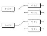
도 3은 일실시예에 따른 광 통신부의 상세 블록도이다. 도 3을 참조하여 본 실시예의 일 양상에 따른 광통신부(110)를 상세히 설명한다. 본 실시예에 따른 광통신부(110)는 광수신부(111)와 광송신부(112)를 포함할 수 있다.3 is a detailed block diagram of an optical communication unit according to an embodiment. 3, the
광수신부(111)는 전술한 바와 같이 연결감지부(121)가 광수신부(111)에서 수신한 광 신호를 분석하고, 타입감지부(122)가 연결된 광 망의 타입을 결정하여 모드설정부(123)가 결정된 광 망의 타입에 맞추어 서비스할 동작의 모드를 설정하면 제어부(130)에서 출력되는 제어 신호에 따라 제1 수신 또는 제 2 수신 모드에 연결하여 OLT로부터 수신되는 각종 광신호를 가입자에게 출력할 수 있다. 즉, 연결된 광 망이 AON이면 제1 수신에 연결하고, 연결된 광 망이 PON이면 제2 수신에 연결하여 어떠한 네트워크에 연결되더라도 수신된 각종 광신호를 효율적으로 처리할 수 있다.The
또한, 광송신부(112)는 감지부(120)에 의해 서비스할 동작 모드가 설정되면 제어부(130)에서 출력되는 제어신호에 따라 제1 송신 또는 제2 송신 모드에 연결하여 OLT로 전송할 각종 상향 신호(Tx)를 전송할 수 있다. 예를 들어, 제1 송신 모드는 AON 방식의 네트워크 망에 연결된 경우 연속 모드로 송신하도록 하는 것이며, 제2 송신 모드는 연결된 광 망이 PON 방식이면 버스트 모드로 송신하도록 하는 것일 수 있다.In addition, when the operation mode to be serviced by the
제어부(130)는 모드설정부(123)에 의해 연결된 광망에 대한 서비스 모드가 설정되면 설정된 모드에 따라서 각종 제어신호를 생성한다. 일 양상에 따르면, 제어부(130)는 감지부(120)의 감지 결과 연결된 광망의 타입이 PON이면 광통신부(110)의 광송신 동작을 버스트 모드(Burst mode)로 설정하도록 하는 제어신호를 생성하고, 연결된 광망의 타입이 AON이면 광통신부(110)의 광송신 동작을 연속모드(continous mode)로 설정하도록 하는 제어 신호를 생성할 수 있다. 광송신부(112)는 제어부(130)에 의해 출력되는 제어신호에 따라 제1 송신 모드 또는 제2 송신 모드에 연결하여 가입자측에서 OLT로 전송되는 각종 신호를 전송할 수 있다.
When the service mode for the optical network connected by the
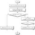
도 4는 일실시예에 따른 광망 종단 장치를 이용한 듀얼 광망 구성 방법의 흐름도이다. 도 5는 일실시예에 따라 듀얼 광망 구성을 위해 연결된 광망 타입을 감지하는 단계의 상세 흐름도이다. 도 4와 도 5를 참조하여 본 실시예에 따른 광망 종단 장치를 이용한 듀얼 광망 구성 방법을 설명한다.4 is a flowchart illustrating a method of configuring a dual light network using a light network terminating apparatus according to an exemplary embodiment of the present invention. 5 is a detailed flow diagram of sensing a type of light network connected for dual-light network configuration according to one embodiment. Referring to FIG. 4 and FIG. 5, a method of configuring a dual optical network using the optical network terminal according to the present embodiment will be described.
듀얼 광망 구성 방법은 먼저, 광망 종단 장치(100)가 광 신호를 수신한다(단계 100). 광망 종단 장치(100)의 광통신부(110)는 OLT로부터 전송되는 하향(Rx) 광 신호를 수신한다.In the dual fiber network construction method, first, the
그 다음, 수신된 신호를 이용하여 연결된 광 망(Optical Network)의 타입을 결정한다(단계 200). 감지부(120)는 광통신부(110)에 의해 수신된 신호(Rx)를 이용하여 연결된 광 망(Optical Network)의 타입을 감지하는데, 이때, 광 망(Optical Network)의 타입은 AON(Active Optical Network) 또는 PON(Passive Optical Network)일 수 있다.The received signal is then used to determine the type of optical network connected (step 200). The
좀 더 구체적으로, 감지부(120)의 연결감지부(121)는 광통신부(110)에 의해 광 신호가 수신되면 광 네트워크에 연결되었음을 감지한다(단계 210).More specifically, when the optical signal is received by the
연결감지부(121)에 의해 네트워크 연결이 감지되면 서비스할 네트워크의 타입을 결정하기 위해 타입감지부(122)는 연결된 네트워크의 타입이 AON인지 PON인지를 감지한다. 즉, 타입감지부(122)는 OLT로부터 수신된 광 신호(Rx)를 분석하여 GTC 프레임과 PLOAM(Physical Layer Operation, Administration and Maintenance) 메시지를 검출되는지 체크한다(단계 220).When the network connection is detected by the
일반적으로 GPON(Gigabit Passive Optical Network)와 같은 PON 방식의 네트워크는 OLT에서 다수의 ONT에 125us 주기로 하향으로 GTC(GPON Transmission Convergence) 프레임을 전송한다. PLOAM(Physical layer OAM) 메시지는 GPON 물리계층의 관리 및 프레임 부 계층의 운용 관리 등의 정보를 전달하는 기능을 수행한다. 하향 PLOAM 셀은 페이로드 안에 몇 개의 제어정보와 상향 슬롯 사용에 대한 그랜트(grant, 허가) 정보와 그에 대한 CRC(Cyclic Redundancy Check)값을 가지고 있다. 또한, CRC로 보호되는 특정 ONU 또는 모든 ONU에게 보내지는 메시지도 가질 수 있으며, 성능감시를 위한 BIP(Bit Interleaved Parity) 값도 가질 수 있다.In general, a PON type network such as a GPON (Gigabit Passive Optical Network) transmits a GTC (GPON Transmission Convergence) frame to a plurality of ONTs in a downward direction at 125 us cycles. The PLOAM (Physical layer OAM) message carries information such as management of the GPON physical layer and operation management of the frame sublayer. The downlink PLOAM cell has grant information and grant CRC (Cyclic Redundancy Check) values for some control information and uplink slots in the payload. It can also have a message sent to a specific ONU protected by a CRC or all ONUs, and can also have a bit interleaved parity (BIP) value for performance monitoring.
따라서, 수신된 광신호에서 GTC 프레임과 PLOAM이 검출되면 광 망의 연결 타입을 PON으로 감지하고, 수신된 광 신호(Rx)에서 GTC 프레임과 PLOAM 메시지가 검출되지 않으면 AON 타입의 광 망에 연결되었음을 감지한다(단계 230). 한편, 추가적인 양상에 따르면, 타입감지부(122)는 수신된 광 신호의 유니데이터 코드의 유효성 체크를 하여(단계 250) 유효한 경우에만 AON 타입의 광망에 연결된 것으로 감지할 수 있다.Therefore, if the GTC frame and the PLOAM are detected in the received optical signal, the connection type of the optical network is detected as PON, and if the GTC frame and the PLOAM message are not detected in the received optical signal Rx, (Step 230). Meanwhile, according to a further aspect, the
그 다음, 모드설정부(123)는 타입감지부(122)에 의해서 연결된 광망의 타입이 결정되면 제어부(130)에 의해 연결된 광망의 타입에 맞추어 제어 신호를 생성하여 제어할 수 있도록 서비스 모드를 그 타입에 맞도록 설정한다. 감지된 광망의 타입이 PON타입이면 서비스 모드를 PON 모드로 설정하고(단계 240), 광망의 타입이 AON 타입이면 서비스 모드를 AON 모드로 설정한다(단계 270).Then, when the type of the optical network connected by the
마지막으로, 감지된 광망의 타입에 맞추어 광통신부의 동작 모드를 제어한다(단계 300). 제어부(130)는 모드설정부(123)에 의해 연결된 광망에 대한 서비스 모드가 설정되면 설정된 모드에 따라서 각종 제어신호를 생성한다. 제어부(130)는 연결된 광망의 타입이 PON이면 광통신부(110)의 광송신 동작을 버스트 모드(Burst mode)로 설정하도록 제어 신호를 생성하고, 연결된 광망의 타입이 AON이면 광통신부(110)의 광송신 동작을 연속모드(continous mode)로 설정하도록 제어 신호를 생성할 수 있다.Finally, the operation mode of the optical communication unit is controlled according to the type of the detected light network (step 300). When the service mode for the optical network connected by the
광수신부(111)는 제어부(130)에서 출력되는 제어 신호에 따라 제1 수신 또는 제 2 수신 모드에 연결하여 OLT로부터 수신되는 각종 광신호를 가입자에게 출력할 수 있다. 예를 들어, 연결된 광 망이 AON이면 제1 수신에 연결하고, 연결된 광 망이 PON이면 제2 수신에 연결하여 어떠한 네트워크에 연결되더라도 수신된 각종 광신호를 효율적으로 처리할 수 있다. 또한, 광송신부(112)는 제어부(130)에서 출력되는 제어신호에 따라 제1 송신 또는 제2 송신 모드에 연결하여 OLT로 전송할 각종 상향 신호(Tx)를 전송할 수 있다. 예를 들어, 연결된 광 망의 타입이 AON이면 제어부(130)의 제어신호에 따라 제1 송신 모드에 연결하여 연속 모드로 송신하도록 하고, 연결된 광 망의 타입이 PON이면 제2 송신 모드에 연결하여 버스트 모드로 송신하도록 할 수 있다.
The
본 발명이 속하는 기술분야의 통상의 지식을 가진 자는 본 발명이 그 기술적 사상이나 필수적인 특징을 변경하지 않고서 다른 구체적인 형태로 실시될 수 있다는 것을 이해할 수 있을 것이다. 그러므로 이상에서 기술한 실시예들은 모든 면에서 예시적인 것이며 한정적이 아닌 것으로 이해해야만 한다. 본 발명의 범위는 상기 상세한 설명보다는 후술하는 특허청구의 범위에 의하여 나타내어지며, 특허청구의 범위의 의미 및 범위 그리고 그 균등 개념으로부터 도출되는 모든 변경 또는 변형된 형태가 본 발명의 범위에 포함되는 것으로 해석되어야 한다.It will be understood by those skilled in the art that the present invention may be embodied in other specific forms without departing from the spirit or essential characteristics thereof. It is therefore to be understood that the above-described embodiments are illustrative in all aspects and not restrictive. The scope of the present invention is defined by the appended claims rather than the foregoing detailed description, and all changes or modifications derived from the meaning and scope of the claims and the equivalents thereof are included in the scope of the present invention Should be interpreted.
100: 광망 종단 장치110: 광통신부
111: 광수신부112: 광송신부
120: 감지부121: 연결감지부
122: 타입감지부123: 모드설정부
130: 제어부100: Optical network terminating apparatus 110: Optical communication unit
111: Optical Receiver 112: Optical Transmitter
120: sensing unit 121: connection sensing unit
122: type sensing unit 123: mode setting unit
130:
Claims (10)
Translated fromKorean상기 광통신부에 의해 수신된 신호를 이용하여 연결된 광 망(Optical Network)의 타입을 감지하는 감지부; 및
상기 감지부에 의해 감지된 광 망의 타입에 맞추어 광통신부의 동작 모드를 제어하는 제어부;를 포함하는 듀얼 광망 구성을 위한 광망 종단 장치.An optical communication unit for transmitting and receiving optical signals;
A sensing unit for sensing a type of an optical network connected using the signal received by the optical communication unit; And
And a controller for controlling the operation mode of the optical communication unit according to the type of the optical network detected by the sensing unit.
AON(Active Optical Network) 또는 PON(Passive Optical Network)인 것을 특징으로 하는 듀얼 광망 구성을 위한 광망 종단 장치.2. The optical network system according to claim 1,
AON (Active Optical Network) or PON (Passive Optical Network).
상기 수신된 신호를 분석하여 PLOAM(Physical Layer Operation, Administration and Maintenance) 데이터가 검출되면 연결된 광 망의 타입을 PON으로 감지하고, 그렇지 않으면 AON으로 감지하는 것을 특징으로 하는 듀얼 광망 구성을 위한 광망 종단 장치.3. The apparatus of claim 2,
Wherein when the received signal is analyzed and PLOAM data is detected, the type of the connected optical network is detected as a PON, and if not detected as AON, the optical network termination for a dual- .
상기 PLOAM 데이터가 감지되지 않으면 상기 수신된 신호의 유니데이터(Unidata) 코드 유효성(Validation)을 체크하여 유효한 경우에 AON으로 감지하는 것을 특징으로 하는 듀얼 광망 구성을 위한 광망 종단 장치.The apparatus of claim 3,
And if the PLOAM data is not detected, the validation of the Unidata code of the received signal is checked, and if the PLOAM data is valid, the AON is detected.
상기 감지부의 감지 결과 연결된 광 망의 타입이 PON이면 광통신부의 송신(Tx) 동작을 버스트 모드(Burst mode)로 설정하고, 연결된 광 망의 타입이 AON이면 광통신부의 송신(Tx) 동작을 연속 모드(Continuous mode)로 설정하는 것을 특징으로 하는 듀얼 광망 구성을 위한 광망 종단 장치.3. The apparatus of claim 2,
(Tx) operation of the optical communication unit is set to a Burst mode if the type of the connected optical network is PON as a result of the detection of the sensing unit, and the transmission (Tx) operation of the optical communication unit is performed in a continuous mode Continuous mode is set to a continuous light mode.
기가비트 수동형 광 네트워크(Gigabit Passive Optical Network, GPON)인 것을 특징으로 하는 듀얼 광망 구성을 위한 광망 종단 장치.The method of claim 3,
Wherein the optical network is a Gigabit Passive Optical Network (GPON).
상기 수신된 신호를 이용하여 연결된 광 망(Optical Network)의 타입을 감지하는 단계; 및
상기 감지된 광 망의 타입에 맞추어 광통신부의 동작 모드를 제어하는 단계;를 포함하는 광망 종단 장치를 이용한 듀얼 광망 구성 방법.Receiving an optical signal;
Sensing a type of a connected optical network using the received signal; And
And controlling an operation mode of the optical communication unit according to the type of the detected optical network.
AON(Active Optical Network) 또는 PON(Passive Optical Network)인 것을 특징으로 하는 광망 종단 장치를 이용한 듀얼 광망 구성 방법.8. The optical network system according to claim 7,
AON (Active Optical Network) or PON (Passive Optical Network).
상기 수신된 신호를 분석하여 PLOAM(Physical Layer Operation, Administration and Maintenance) 데이터를 검출하는 단계;
상기 검출 단계에서 PLOAM 데이터가 검출되면 연결된 광 망의 타입을 PON으로 감지하는 단계;
상기 감지 단계에서 PLOAM 데이터가 검출되지 않으면 상기 수신된 신호의 유니데이터(Unidata) 코드의 유효성(Validation)을 체크하는 단계; 및
상기 유효성 체크 단계의 체크 결과 유효한 경우 연결된 광 망의 타입을 AON으로 감지하는 단계;를 포함하는 것을 특징으로 하는 광망 종단 장치를 이용한 듀얼 광망 구성 방법.9. The method of claim 8, wherein sensing the type of the optical network comprises:
Analyzing the received signal to detect PLOAM (Physical Layer Operation, Administration and Maintenance) data;
Detecting PLOAM data in the detection step as a PON when the PLOAM data is detected;
Checking the validation of the Unidata code of the received signal if the PLOAM data is not detected in the detecting step; And
And detecting the type of the connected optical network as AON when the check result of the validity check step is valid.
상기 광 망의 타입을 감지하는 단계에서 연결된 광 망의 타입을 PON으로 감지하면 광통신부의 송신(Tx) 동작을 버스트 모드(Burst mode)로 설정하고, 연결된 광 망의 타입을 AON으로 감지하면 광통신부의 송신(Tx) 동작을 연속 모드(Continuous mode)로 설정하는 것을 특징으로 하는 광망 종단 장치를 이용한 듀얼 광망 구성 방법.9. The method of claim 8, wherein the controlling the transmission /
If the type of the connected optical network is detected by the PON in the step of detecting the type of the optical network, the transmission (Tx) operation of the optical communication unit is set to the Burst mode, and if the type of the optical network is detected as AON, And setting a transmission (Tx) operation to a continuous mode.
Priority Applications (1)
| Application Number | Priority Date | Filing Date | Title |
|---|---|---|---|
| KR1020110117187AKR101266371B1 (en) | 2011-11-10 | 2011-11-10 | Optical network terminal and method for configuring dual optical network using the optical network terminal |
Applications Claiming Priority (1)
| Application Number | Priority Date | Filing Date | Title |
|---|---|---|---|
| KR1020110117187AKR101266371B1 (en) | 2011-11-10 | 2011-11-10 | Optical network terminal and method for configuring dual optical network using the optical network terminal |
Publications (2)
| Publication Number | Publication Date |
|---|---|
| KR20130051822Atrue KR20130051822A (en) | 2013-05-21 |
| KR101266371B1 KR101266371B1 (en) | 2013-05-22 |
Family
ID=48661683
Family Applications (1)
| Application Number | Title | Priority Date | Filing Date |
|---|---|---|---|
| KR1020110117187AActiveKR101266371B1 (en) | 2011-11-10 | 2011-11-10 | Optical network terminal and method for configuring dual optical network using the optical network terminal |
Country Status (1)
| Country | Link |
|---|---|
| KR (1) | KR101266371B1 (en) |
Family Cites Families (3)
| Publication number | Priority date | Publication date | Assignee | Title |
|---|---|---|---|---|
| KR100723874B1 (en) | 2005-12-09 | 2007-05-31 | 한국전자통신연구원 | TMA OOOTT System for Broadcast Service |
| KR100738553B1 (en) | 2006-01-18 | 2007-07-11 | 삼성전자주식회사 | Complex network management system and method |
| JP5026467B2 (en)* | 2009-04-27 | 2012-09-12 | 日本電信電話株式会社 | COMMUNICATION MONITORING DEVICE, COMMUNICATION MONITORING METHOD, AND PROGRAM |
- 2011
- 2011-11-10KRKR1020110117187Apatent/KR101266371B1/enactiveActive
Also Published As
| Publication number | Publication date |
|---|---|
| KR101266371B1 (en) | 2013-05-22 |
Similar Documents
| Publication | Publication Date | Title |
|---|---|---|
| US10651938B2 (en) | Broadband optical network apparatus and method | |
| US10454574B2 (en) | System and method for performing in-service optical network certification | |
| US7729612B2 (en) | Method and system for maintenance of a passive optical network | |
| KR100584383B1 (en) | Optical fiber termination device for managing link status of optical fiber subscriber devices and Gigabit Ethernet based passive optical subscriber network | |
| US11146330B2 (en) | System and method for performing in-service optical network certification | |
| EP2207310B1 (en) | Optical network unit | |
| US7555214B2 (en) | Method of ethernet frame forward error correction initialization and auto-negotiation | |
| KR100738559B1 (en) | Bandwidth setting method of EPON system and apparatus therefor | |
| WO2007009949A1 (en) | Method and apparatus enabling end-to-end resilience in pons | |
| EP2154832B1 (en) | Optical access network | |
| CN102149027B (en) | Path switching method, system and downlink data transmission method | |
| CN101317349A (en) | A passive optical network maintenance method, optical network unit and optical line terminal | |
| Butt et al. | Evolution of access network from copper to PON-Current status | |
| Kim et al. | Low‐Cost, Low‐Power, High‐Capacity 3R OEO‐Type Reach Extender for a Long‐Reach TDMA‐PON | |
| KR101266371B1 (en) | Optical network terminal and method for configuring dual optical network using the optical network terminal | |
| KR101251302B1 (en) | Passive optical network and the method of detecting ont | |
| EP2795817B1 (en) | System and method for providing resilience in communication networks | |
| KR20120071099A (en) | Optical line terminal device and optical network device | |
| JP5640724B2 (en) | Subscriber communication system, communication control method, and program | |
| Neri et al. | Passive Optical Networks | |
| Inohara et al. | Reconfigurable WDM/TDM-PON ring-architecture by using all-optical wavelength converter and injection-locked FP-LD | |
| Tan et al. | Dynamic wavelength and bandwidth allocation schemes in WDM-upgraded EPON |
Legal Events
| Date | Code | Title | Description |
|---|---|---|---|
| A201 | Request for examination | ||
| PA0109 | Patent application | Patent event code:PA01091R01D Comment text:Patent Application Patent event date:20111110 | |
| PA0201 | Request for examination | ||
| E902 | Notification of reason for refusal | ||
| PE0902 | Notice of grounds for rejection | Comment text:Notification of reason for refusal Patent event date:20130127 Patent event code:PE09021S01D | |
| E701 | Decision to grant or registration of patent right | ||
| PE0701 | Decision of registration | Patent event code:PE07011S01D Comment text:Decision to Grant Registration Patent event date:20130429 | |
| GRNT | Written decision to grant | ||
| PR0701 | Registration of establishment | Comment text:Registration of Establishment Patent event date:20130515 Patent event code:PR07011E01D | |
| PR1002 | Payment of registration fee | Payment date:20130515 End annual number:3 Start annual number:1 | |
| PG1501 | Laying open of application | ||
| PG1601 | Publication of registration | ||
| FPAY | Annual fee payment | Payment date:20160511 Year of fee payment:4 | |
| PR1001 | Payment of annual fee | Payment date:20160511 Start annual number:4 End annual number:4 | |
| FPAY | Annual fee payment | Payment date:20170511 Year of fee payment:5 | |
| PR1001 | Payment of annual fee | Payment date:20170511 Start annual number:5 End annual number:5 | |
| FPAY | Annual fee payment | Payment date:20190424 Year of fee payment:7 | |
| PR1001 | Payment of annual fee | Payment date:20190424 Start annual number:7 End annual number:7 | |
| PR1001 | Payment of annual fee | Payment date:20200512 Start annual number:8 End annual number:8 | |
| PR1001 | Payment of annual fee | Payment date:20210510 Start annual number:9 End annual number:9 | |
| PR1001 | Payment of annual fee | Payment date:20220512 Start annual number:10 End annual number:10 | |
| PR1001 | Payment of annual fee | Payment date:20230515 Start annual number:11 End annual number:11 | |
| PR1001 | Payment of annual fee | Payment date:20240514 Start annual number:12 End annual number:12 |