KR20130040832A - Electronic counter measure system - Google Patents
Electronic counter measure systemDownload PDFInfo
- Publication number
- KR20130040832A KR20130040832AKR1020127027565AKR20127027565AKR20130040832AKR 20130040832 AKR20130040832 AKR 20130040832AKR 1020127027565 AKR1020127027565 AKR 1020127027565AKR 20127027565 AKR20127027565 AKR 20127027565AKR 20130040832 AKR20130040832 AKR 20130040832A
- Authority
- KR
- South Korea
- Prior art keywords
- signal
- phase
- transceiver
- antenna
- received
- Prior art date
- Legal status (The legal status is an assumption and is not a legal conclusion. Google has not performed a legal analysis and makes no representation as to the accuracy of the status listed.)
- Ceased
Links
- 230000000694effectsEffects0.000claimsabstractdescription13
- 238000004891communicationMethods0.000claimsdescription89
- 238000000034methodMethods0.000claimsdescription45
- 230000010363phase shiftEffects0.000claimsdescription37
- 230000005540biological transmissionEffects0.000claimsdescription26
- 239000002828fuel tankSubstances0.000claimsdescription3
- 230000001934delayEffects0.000claimsdescription2
- 238000005259measurementMethods0.000claimsdescription2
- 230000001276controlling effectEffects0.000claims2
- 230000000630rising effectEffects0.000claims2
- 230000002194synthesizing effectEffects0.000claims1
- 230000002730additional effectEffects0.000description5
- 230000009977dual effectEffects0.000description5
- 238000001914filtrationMethods0.000description5
- 238000012545processingMethods0.000description5
- 238000005070samplingMethods0.000description5
- 238000006243chemical reactionMethods0.000description4
- 238000005516engineering processMethods0.000description3
- 230000005855radiationEffects0.000description3
- 238000003491arrayMethods0.000description2
- 230000001413cellular effectEffects0.000description2
- 238000001514detection methodMethods0.000description2
- 230000002452interceptive effectEffects0.000description2
- 238000012423maintenanceMethods0.000description2
- 239000000463materialSubstances0.000description2
- 230000003111delayed effectEffects0.000description1
- 230000017525heat dissipationEffects0.000description1
- 230000005404monopoleEffects0.000description1
- 239000007787solidSubstances0.000description1
Images


Classifications
- G—PHYSICS
- G01—MEASURING; TESTING
- G01S—RADIO DIRECTION-FINDING; RADIO NAVIGATION; DETERMINING DISTANCE OR VELOCITY BY USE OF RADIO WAVES; LOCATING OR PRESENCE-DETECTING BY USE OF THE REFLECTION OR RERADIATION OF RADIO WAVES; ANALOGOUS ARRANGEMENTS USING OTHER WAVES
- G01S7/00—Details of systems according to groups G01S13/00, G01S15/00, G01S17/00
- G01S7/02—Details of systems according to groups G01S13/00, G01S15/00, G01S17/00 of systems according to group G01S13/00
- G01S7/38—Jamming means, e.g. producing false echoes
- H—ELECTRICITY
- H04—ELECTRIC COMMUNICATION TECHNIQUE
- H04K—SECRET COMMUNICATION; JAMMING OF COMMUNICATION
- H04K3/00—Jamming of communication; Counter-measures
- H04K3/60—Jamming involving special techniques
- H04K3/65—Jamming involving special techniques using deceptive jamming or spoofing, e.g. transmission of false signals for premature triggering of RCIED, for forced connection or disconnection to/from a network or for generation of dummy target signal
Landscapes
- Engineering & Computer Science (AREA)
- Computer Networks & Wireless Communication (AREA)
- Physics & Mathematics (AREA)
- General Physics & Mathematics (AREA)
- Radar, Positioning & Navigation (AREA)
- Remote Sensing (AREA)
- Signal Processing (AREA)
- Radar Systems Or Details Thereof (AREA)
- Variable-Direction Aerials And Aerial Arrays (AREA)
- Near-Field Transmission Systems (AREA)
Abstract
Translated fromKorean
Description
Translated fromKorean본원 기술의 분야FIELD OF THE INVENTION
본원의 기법은 일반적으로 전자 대응책 시스템에 관한 것이며, 구체적으로 이중 대역 전자 대응책 시스템에 관한 것이다.
The technique herein relates generally to an electronic countermeasure system, and more particularly to a dual band electronic countermeasure system.
본원 기술의 배경Background of the present technology
ECM(Electronic Counter Measure, 전자 대응책) 시스템은 넓은 범위의 주파수에서, 예를 들어, VHF 주파수 대역과 K 주파수 대역(즉, IEEE 무선 대역에 따르는 주파수 대역) 사이에서 작동하는 것이 일반적이다. 이들 시스템은 복수의 서브-시스템으로 분할되며, 복수의 서브-시스템 각각은 대응하는 주파수 범위에서 작동하고, 개별적으로 패키징되는 것이 일반적이다. 예를 들어, ALQ-99 시스템은 5개의 서로 다른 포드(pod)에 하우징된다. 더욱이, 이러한 복수의 서브-시스템은 상당한 전력 소모를 야기한다. ECM 시스템의 서브-시스템들 중 하나는 신호 재-송신 시스템일 수 있다. 신호가 수신된 방향으로 신호(즉, 동일한 신호, 또는 상이한 신호)를 재송신하는 것은 재송신되는 신호의 신호대잡음 비(SNR)를 증가시킬 수 있다. 신호가 수신된 방향으로 신호를 재송신하는 것의 또 다른 적용예가 ECM 시스템에 있다. 예를 들어, 레이더(RADAR)에 의해 송신되는 신호와의 간섭에 의해, 운송수단(가령, 항공기, 선박, 차량)이 레이더에 의한 상기 운송수단 및 다른 운송수단의 검출을 악화시킬 수 있다. 레이더 신호와 간섭을 일으키기 위한 해당업계 종사자에게 알려진 방법에 따르면, 운송수단은 레이더 신호와 실질적으로 유사한 지향성 간섭 신호를 레이더 쪽으로 송신한다. 지향성 간섭 신호가 레이더 신호와 실질적으로 유사하기 때문에, 레이더는 간섭 신호와 운송수단으로부터 반사되는 레이더 신호를 구별할 수 없다. 따라서 간섭 신호는 레이더 신호를 '재밍(jam)'한다. 지향성 신호를 송신하는 것은, 지향성 안테나(가령, 혼 안테나(horn antenna))를 이용하는 것, 또는 어레이 내 안테나들의 상대적 위치가 알려져 있는 위상 안테나 어레이를 이용하는 것을 필요로 한다.Electronic Counter Measure (ECM) systems generally operate over a wide range of frequencies, for example, between the VHF frequency band and the K frequency band (ie, the frequency band according to the IEEE radio band). These systems are divided into a plurality of sub-systems, each of which operates in a corresponding frequency range and is typically packaged separately. For example, the ALQ-99 system is housed in five different pods. Moreover, these multiple sub-systems cause significant power consumption. One of the sub-systems of the ECM system may be a signal re-transmission system. Retransmitting a signal (ie, the same signal, or a different signal) in the direction in which the signal was received may increase the signal to noise ratio (SNR) of the retransmitted signal. Another application of retransmitting a signal in the direction in which the signal is received is in the ECM system. For example, interference with a signal transmitted by a radar RADAR may cause a vehicle (eg, an aircraft, a ship, a vehicle) to exacerbate the detection of the vehicle and other vehicles by the radar. According to a method known to those skilled in the art for interfering with the radar signal, the vehicle transmits a directional interference signal to the radar that is substantially similar to the radar signal. Since the directional interference signal is substantially similar to the radar signal, the radar cannot distinguish between the interference signal and the radar signal reflected from the vehicle. The interfering signal thus 'jams' the radar signal. Transmitting a directional signal requires using a directional antenna (eg a horn antenna), or using a phased antenna array where the relative position of the antennas in the array is known.
고우날리스(Gounalis)에게 허여된 미국 특허 제7,248,203호, 명칭 "System and Method for Detecting and Jamming Emitter Signals"는 하나 이상의 안테나와, 상기 안테나에 의해 수신된 신호를 수신 및 프로세싱하는 프로세싱 시스템을 포함하는 검출 시스템을 설명한다. 예를 들어, 이들 신호는, 레이더, 통신, 및 그 밖의 다른 유형의 신호를 포함하는, 복수의 주파수 중 어느 하나에서 송신된 전자기 신호이다. 수신된 신호는 프로세서에 전달된다. 프로세서는 스캔 전략(scan strategy)에 의해 지정된 주파수 대역을 관찰함으로써, 하나 이상의 위협(threat)을 검출하는 스캔 전략을 구현한다. 시스템은 스캔 전략을 결정한다. 스캔 전략은 이미터(emitter) 또는 이미터 파라미터의 선택된 세트의 신호 인터셉트를 최적화하도록 결정된다. 또한 스캔 전략은 각각의 이미터에 대한 "드웰(dwell)"을 최소화하도록 결정된다. 드웰은 스캔 자원, 가령, 주파수 범위, 스캔 주기, 및 재방문 시간(revisit time)을 지정한다. 프로세서는 지정된 "드웰(dwell)"에서 수신된 신호에 따라 이미터 파라미터를 결정한다. 프로세서는 재밍 신호(jamming signal)를 결정하고, 이 재밍 신호를 재머 송신기(jammer transmitter)에게 제공하며, 상기 재머 송신기는 이미터를 "재밍"한다.U.S. Pat.No. 7,248,203, entitled "System and Method for Detecting and Jamming Emitter Signals," issued to Gounalis, includes one or more antennas and a processing system for receiving and processing signals received by the antennas. The detection system will be described. For example, these signals are electromagnetic signals transmitted at any one of a plurality of frequencies, including radar, communication, and other types of signals. The received signal is delivered to the processor. The processor implements a scan strategy that detects one or more threats by observing the frequency band specified by the scan strategy. The system determines the scan strategy. The scan strategy is determined to optimize the signal intercept of the selected set of emitters or emitter parameters. The scan strategy is also determined to minimize the "dwell" for each emitter. The dwell specifies the scan resource, such as frequency range, scan period, and revisit time. The processor determines the emitter parameter according to the signal received at the designated " dwell. &Quot; The processor determines a jamming signal and provides this jamming signal to a jammer transmitter, which jamming the emitter.
핵커(Hacker)에게 허여된 미국 특허 제4,467,328호, 명칭 "RADAR Jammer With an Antenna Array of Pseudo-Randomly Spaced Radiating Elements"는, 무작위로 이격된 요소들을 갖는 안테나 어레이, 재머 송신기, 전력 분배기, 및 복수의 위상 편이 요소들을 포함하는 레이더 재머(RADAR jammer)에 관한 것이다. 상기 레이더 재머는 4개의 모노펄스 혼 안테나, 모노펄스 수신기, 위상-편이기 로직 및 위상-편이기 드라이버를 포함하는 지향성 파인딩 시스템(directional finding system)을 더 포함한다. 전력 분배기는 재머 송신기 및 위상 편이 요소들과 연결된다. 위상-편이기 드라이버는 위상 편이 요소들 및 위상-편이기 로직과 연결된다. 모노펄스 수신기는 4개의 혼 안테나 및 위상-편이기 로직과 연결된다. 위상 편이 요소들은 안테나 어레이 요소들과 더 연결된다.US Pat. No. 4,467,328, entitled "RADAR Jammer With an Antenna Array of Pseudo-Randomly Spaced Radiating Elements," to Hacker, discloses an antenna array, a jammer transmitter, a power divider, and a plurality of randomly spaced elements. A radar jammer comprising phase shift elements. The radar jammer further includes a directional finding system comprising four monopulse horn antennas, a monopulse receiver, phase-shifter logic and a phase-shifter driver. The power divider is connected with the jammer transmitter and phase shifting elements. The phase-shifter driver is coupled with phase shifting elements and phase-shifter logic. The monopulse receiver is connected with four horn antennas and phase-shifter logic. The phase shift elements are further connected with antenna array elements.
모노펄스 수신기는 혼 안테나로부터 신호를 수신하고, 검출된 위협의 방향을 결정하며, 위협 방향을 나타내는 신호를 발생시킨다. 위상-편이기는, 안테나 어레이 요소들의 간격의 값이 그곳에 저장되게 하고(즉, 무작위로 분포된 안테나 요소들의 간격 치수가 알려짐), 검출된 위협 쪽으로 지향되는 재밍 복사의 하나의 좁고 높은 전력 빔을 만들기 위해 복사 요소의 전력 신호의 위상을 변경하도록 의도된 위상 편이 신호의 세트를 결정한다. 복사 요소의 확산 속성 때문에, 검출된 방향에서 레이더 위협을 타파하기 위해 메인 빔은 훨씬 더 좁을 것이며 훨씬 더 낮은 에너지를 필요로 할 것이 제안된다. 따라서, 허위로 발생한 빔과 관련된 잔여 에너지가 모든 곳에 산재하는 전체 위협 볼륨에 걸쳐 확산된다.The monopulse receiver receives a signal from the horn antenna, determines the direction of the detected threat, and generates a signal indicative of the threat direction. Phase-shifting allows the value of the spacing of the antenna array elements to be stored there (ie the spacing dimension of randomly distributed antenna elements is known), creating one narrow, high power beam of jamming radiation directed towards the detected threat. To determine the set of phase shift signals intended to change the phase of the power signal of the radiation element. Because of the spreading nature of the radiation element, it is proposed that the main beam will be much narrower and require much lower energy to counter radar threats in the detected direction. Thus, the residual energy associated with the falsely generated beam is spread over the entire threat volume scattered everywhere.
힐스(Hills)에게 허여된 미국 특허 제4,472,719호, 명칭 "ECM Multiple-Target Retrodirective Antenna"는, 복수의 안테나 요소들을 각각 포함하는 수신 및 송신 선형 안테나 어레이에 관한 것이다. 각각의 안테나 요소는 수평면에 장착되고, 동일한 길이의 송신선을 통해 마이크로웨이브로 연결된다. 마이크로웨이브 렌즈는, 파장의 절반 미만만큼 이격된 2개의 평행인 전도 표면으로 구성된다. 마이크로웨이브 렌즈의 각각의 출력 포트는 방위각에서의 개별 빔 패턴에 대응한다. 로직 프로세서는 각각의 수신기로부터의 전압을 이진 전압(binary voltage)으로 변환한다. 상기 이진 전압은, 외부 소스로부터 ECM 신호를 수신하는 스위칭 장치로 게이팅된다. 로직 프로세서는 신호를 검출하고, 원하는 빔에 따라 신호를 송신하도록 스위치를 활성화한다.
US Pat. No. 4,472,719, entitled "ECM Multiple-Target Retrodirective Antenna," to Hills, relates to a receive and transmit linear antenna array each comprising a plurality of antenna elements. Each antenna element is mounted in a horizontal plane and connected to the microwave via transmission lines of equal length. The microwave lens consists of two parallel conducting surfaces spaced by less than half of the wavelength. Each output port of the microwave lens corresponds to an individual beam pattern at an azimuth angle. The logic processor converts the voltage from each receiver into a binary voltage. The binary voltage is gated to a switching device that receives an ECM signal from an external source. The logic processor detects the signal and activates the switch to transmit the signal in accordance with the desired beam.
본원 기술의 개요Overview of the present technology
본원의 기법의 목적은, 전자 대응책(electronic counter measure)을 위한 신규한 시스템을 제공하는 것이다.It is an object of the technique herein to provide a novel system for electronic counter measure.
따라서, 본원의 기법에 따르면, 전술적 전자 대응책 시스템이 제공된다. 시스템은 제 1 역지향성 송수신기 서브-시스템과 제어기를 포함한다. 제어기는 제 1 역지향성 송수신기 서브-시스템과 연결된다. 제 1 역지향성 송수신기 서브-시스템은 제 1 주파수 대역에서 신호를 수신한다. 제 1 역지향성 송수신기 서브-시스템은, 적어도 실질적으로 소스 신호가 수신된 방향으로 신호를 재-송신한다. 제 1 역지향성 송수신기 서브-시스템은 복수의 블레이드 안테나를 포함한다. 제어기는 제 1 역지향성 송수신기 서브-시스템의 활동을 제어한다. 제어기는 제 1 역지향성 송수신기 서브-시스템의 미션을 추가로 관리한다.Thus, according to the techniques herein, a tactical electronic countermeasure system is provided. The system includes a first reverse directional transceiver sub-system and a controller. The controller is coupled with the first reverse directional transceiver sub-system. The first reverse directional transceiver sub-system receives a signal in a first frequency band. The first reverse directional transceiver sub-system re-transmits the signal at least substantially in the direction in which the source signal was received. The first reverse directional transceiver sub-system includes a plurality of blade antennas. The controller controls the activity of the first reverse directional transceiver sub-system. The controller further manages the mission of the first reverse directional transceiver sub-system.
따라서 본원의 기법의 또 하나의 양태에 따르면, 이중 대역(dual band) 전술적 전자 대응책 시스템이 제공된다. 이중 대역 전술적 전자 대응책 시스템은 제 1 대역 송수신기 서브-시스템과 제어기를 포함한다. 제어기는 제 1 대역 송수신기 서브-시스템과 연결된다. 제 1 대역 송수신기 서브-시스템은 통신 및 레이더(RADAR) 디지털 송수신기와 제 1 통신 송수신기를 포함한다. 제어기는 제 1 대역 송수신기 서브-시스템의 활동을 제어한다. 제어기는 제 1 대역 송수신기 서브-시스템의 미션을 더 관리한다.Thus, according to another aspect of the techniques herein, a dual band tactical electronic countermeasure system is provided. The dual band tactical electronic countermeasure system includes a first band transceiver sub-system and a controller. The controller is coupled with the first band transceiver sub-system. The first band transceiver sub-system includes a communication and radar (RADAR) digital transceiver and a first communication transceiver. The controller controls the activity of the first band transceiver sub-system. The controller further manages the mission of the first band transceiver sub-system.
따라서, 본원의 기법의 또 다른 양태에 따라, 전술적 전자 대응책 시스템이 제공된다. 전술적 전자 대응책 시스템은 제 1 대역 송수신 어레이, 제 2 대역 송수신기 모듈, 레이더 수신기, 통신 수신기, 신호 소스 생성기, 스위치, 및 제어기를 포함한다. 제 1 대역 송수신 어레이는 복수의 블레이드 안테나와, 각각의 안테나와 연결되는 복수의 제 1 대역 송수신기 모듈을 포함한다. 제 2 대역 송수신기 모듈은 각자의 안테나와 연결된다. 레이더 수신기는, 수신 주기 동안, 제 1 대역 송수신기 모듈 및 제 2 대역 송수신기 모듈 각각과 연결된다. 통신 수신기는, 수신 주기 동안, 제 1 대역 송수신기 모듈 및 제 2 대역 송수신기 모듈 각각과 연결된다. 신호 소스 생성기는, 제 1 송신 주기 동안, 제 1 대역 송수신기 모듈과 연결된다. 신호 소스 생성기는, 제 2 송신 주기 동안, 제 2 대역 송수신기 모듈과 더 연결된다. 스위치는 레이더 수신기, 통신 수신기, 및 신호 소스 생성기와 연결된다. 제어기는 스위치, 레이더(RADAR) 수신기, 통신 수신기, 및 신호 소스 생성기와 연결된다.Thus, in accordance with another aspect of the techniques herein, a tactical electronic countermeasure system is provided. The tactical electronic countermeasure system includes a first band transceiver array, a second band transceiver module, a radar receiver, a communication receiver, a signal source generator, a switch, and a controller. The first band transceiver array includes a plurality of blade antennas and a plurality of first band transceiver modules connected to each antenna. The second band transceiver module is connected to its antenna. The radar receiver is connected with each of the first band transceiver module and the second band transceiver module during a reception period. The communication receiver is connected with each of the first band transceiver module and the second band transceiver module during a reception period. The signal source generator is coupled with the first band transceiver module during the first transmission period. The signal source generator is further coupled with the second band transceiver module during the second transmission period. The switch is connected with the radar receiver, the communication receiver, and the signal source generator. The controller is coupled to a switch, a radar (RADAR) receiver, a communication receiver, and a signal source generator.
제 1 대역 송수신기 모듈 각각은 수신 주기 동안 이미터에 의해 송신된 소스 신호를 수신한다. 각각의 제 1 대역 송수신기 모듈은 중간 신호의 위상을 각각의 상대적 위상-편이치 만큼 더 편이시키고, 위상 편이된 중간 신호를 각자의 안테나를 통해 송신한다. 제 2 대역 송수신기 모듈은, 수신 주기 동안, 이미터에 의해 송신되는 소스 신호를 수신한다. 제 2 대역 송수신기 모듈은 각자의 안테나를 통해 중간 신호를 더 송신한다. 레이더 수신기는 제 1 및 제 2 주파수 대역에 대응하는 제 2 수신된 레이더 신호 파라미터를 결정한다. 상기 레이더 수신기는 수신된 신호 각각에 대해, 기준 위상에 대한 각자의 상대적 위상을 더 결정하고, 이로써, 제 1 대역 송수신기 모듈의 각각의 상대적 위상을 결정한다. 레이더 수신기는 각각의 상대적 위상을 각각의 제 1 대역 송수신기 모듈에게 더 제공한다. 통신 수신기는 제 1 및 제 2 주파수 대역에 대응하는 제 2 수신된 통신 신호 파라미터를 결정한다. 통신 수신기는, 수신된 신호 각각에 대해, 기준 위상에 대한 각각의 상대적 위상을 더 결정하고, 이로써, 각각의 제 1 대역 송수신기 모듈에 대한 각각의 상대적 위상을 결정한다. 통신 수신기는 각각의 상대적 위상을 각각의 제 1 대역 송수신기 모듈에게 더 제공한다.Each of the first band transceiver modules receives a source signal transmitted by the emitter during a receive period. Each first band transceiver module further shifts the phase of the intermediate signal by each relative phase-shift, and transmits the phase shifted intermediate signal through its respective antenna. The second band transceiver module receives a source signal transmitted by the emitter during the reception period. The second band transceiver module further transmits an intermediate signal through its antenna. The radar receiver determines a second received radar signal parameter corresponding to the first and second frequency bands. The radar receiver further determines a respective relative phase with respect to the reference phase for each of the received signals, thereby determining each relative phase of the first band transceiver module. The radar receiver further provides each relative phase to each first band transceiver module. The communication receiver determines a second received communication signal parameter corresponding to the first and second frequency bands. The communication receiver further determines, for each received signal, each relative phase relative to the reference phase, thereby determining each relative phase for each first band transceiver module. The communication receiver further provides each relative phase to each first band transceiver module.
신호 소스 생성기는 제 1 수신된 신호 파라미터에 따라 제 1 중간 신호를 생성한다. 신호 소스 생성기는 제 2 수신된 신호 파라미터에 따라 제 2 중간 신호를 생성한다. 신호 소스 생성기는 제 1 송신 주기 동안 제 1 중간 신호를 송수신기 모듈에게 제공한다. 신호 소스 생성기는 제 2 송신 주기 동안 제 2 중간 신호를 제 2 대역 송수신기 모듈에게 제공한다. 제어기는 스위치에게 수신 주기 동안 제 1 대역 송수신기 모듈 및 제 2 대역 송수신기 모듈을 레이더 수신기 및 통신 수신기와 연결하도록 지시한다. 제어기는 스위치에게 신호 소스 생성기를 제 1 송신 주기 동안 제 1 대역 송수신기 모듈과 연결하고, 제 2 송신 주기 동안 제 2 대역 송수신기 모듈과 연결하도록 더 지시한다. 제어기는 활동을 더 제어하며, 레이더 수신기, 통신 수신기, 및 신호 소스 생성기의 미션을 더 관리한다.The signal source generator generates a first intermediate signal in accordance with the first received signal parameter. The signal source generator generates a second intermediate signal in accordance with the second received signal parameter. The signal source generator provides a first intermediate signal to the transceiver module during the first transmission period. The signal source generator provides a second intermediate signal to the second band transceiver module during a second transmission period. The controller instructs the switch to connect the first band transceiver module and the second band transceiver module with the radar receiver and the communication receiver during a receive period. The controller further instructs the switch to connect the signal source generator with the first band transceiver module during the first transmission period and with the second band transceiver module during the second transmission period. The controller further controls the activity and further manages the mission of the radar receiver, communication receiver, and signal source generator.
도면의 간단한 설명
본원의 기법은, 도면과 연계된 다음의 상세한 설명에 의해 더 완벽하게 이해되고 인지될 것이다.
도 1은 본원 기법의 하나의 실시예에 따라 구성되고 작동하는 저주파수 전술적 ECM 시스템을 개략적으로 도시한다.
도 2는 본원 기법의 또 다른 실시예에 따라 구성되고 작동하는 제 1 역지향성 송수신기 서브-시스템을 개략적으로 도시한다.
도 3은 본원 기법의 또 다른 실시예에 따라 구성되고 작동하는 제 1 역지향성 송수신기 서브-시스템을 개략적으로 도시한다.
도 4A는 안테나 어레이의 안테나들 중 하나에 의해 수신된 신호를 나타낸다.
도 4B는 도 4A의 신호의 시간 반전된 버전이다.
도 4C는 안테나 어레이의 안테나들 중 하나에 의해 수신된 임펄스를 포함하는 이산 신호의 표현이다.
도 4D는 도 4C와 관련하여 시간 반전된 것이다.
도 4E는 본원 기법의 또 다른 실시예에 따라 구성되고 작동하는 제 1 역지향성 송수신기 서브-시스템을 개략적으로 도시한다.
도 5는 본원 기법의 또 다른 실시예에 따라 구성되고 작동하는 제 2 송신 서브-시스템을 개략적으로 도시한다.
도 6은 본원 기법의 또 다른 실시예에 따라 구성되고 작동하는 저주파수 전술적 ECM 시스템을 개략적으로 도시한다.
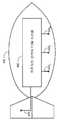
도 7은 본원 기법의 추가적인 실시예에 따르는, 공기역학적 용기 내에 하우징되는 저주파수 전술적 ECM 시스템을 개략적으로 도시한다.
도 8은 본원 기법의 또 다른 실시예에 따르는, 공기역학적 용기 내에 하우징되는 저주파수 전술적 ECM 시스템을 개략적으로 도시한다.Brief Description of Drawings
The techniques herein will be more fully understood and appreciated by the following detailed description in conjunction with the drawings.
1 schematically illustrates a low frequency tactical ECM system constructed and operating in accordance with one embodiment of the present technique.
2 schematically illustrates a first reverse directional transceiver sub-system constructed and operative in accordance with another embodiment of the present technique.
3 schematically illustrates a first reverse directional transceiver sub-system constructed and operative in accordance with another embodiment of the present technique.
4A shows a signal received by one of the antennas of an antenna array.
4B is a time inverted version of the signal of FIG. 4A.
4C is a representation of a discrete signal comprising an impulse received by one of the antennas of an antenna array.
4D is time reversed with respect to FIG. 4C.
4E schematically illustrates a first reverse directional transceiver sub-system constructed and operative in accordance with another embodiment of the present technique.
5 schematically illustrates a second transmission sub-system constructed and operative in accordance with another embodiment of the present technique.
6 schematically illustrates a low frequency tactical ECM system constructed and operating in accordance with another embodiment of the present technique.
7 schematically illustrates a low frequency tactical ECM system housed in an aerodynamic container, in accordance with a further embodiment of the present technique.
8 schematically illustrates a low frequency tactical ECM system housed in an aerodynamic container, according to another embodiment of the present technique.
실시예의Example 상세한 설명 details
본원의 기법은 제 1 역지향성(retro-directive) 송수신기 서브-시스템과 제 2 송수신기 서브-시스템을 포함하는 저주파수의 전술적 ECM 시스템을 제공함으로써 기존 기술의 단점을 극복한다. 저주파수 이중 전술적 ECM 시스템은, 특히, VHF 대역과 C 주파수 대역(즉, IEEE 무선 대역에 따르는 주파수 대역) 사이에서 작동한다. 제 1 송수신기 서브-시스템은 제 1 주파수 대역에서, 특히, UHF 대역과 C 주파수 대역 사이에서 작동한다. 제 1 송수신기 서브-시스템은, 안테나들의 상대적 위치가 알려져 있는 위상 안테나 어레이를 이용하여 신호를 신호 소스, 가령, 통신 장치 또는 레이더(RADAR) 쪽으로 재-송신한다. 안테나 어레이 내 각각의 안테나에 의해 소스 신호가 수신되고 기록된다. 그 후, 서브-시스템은 수신된 소스 신호를, 상기 신호를 수신한 것과 동일한 안테나에 의해, 재-송신하여, 재-송신된 신호가 적어도 실질적으로 소스 신호가 수신된 방향으로 송신되게 한다. 본원의 기법에 따르는 제 1 역지향성 송수신기 서브-시스템은 재-송신된 신호의 상대적 위상(즉, 안테나 어레이의 각각의 쌍의 안테나들 간의 상대적 위상)을, 수신된 소스 신호의 상대적 위상의 음의 값으로부터, 재-송신된 신호에 추가적인 영향을 미치도록(가령, 디-포커싱, 멀티-빔) 변경할 수 있다. 제 2 송신 서브-시스템은 제 2 주파수 대역에서, 특히, VHF 대역과 UHF 대역 사이에서 동작한다. 제 2 송신 서브-시스템은 디지털 송신기를 포함한다.The technique herein overcomes the shortcomings of the existing technology by providing a low frequency tactical ECM system that includes a first retro-directive transceiver sub-system and a second transceiver sub-system. The low frequency dual tactical ECM system operates in particular between the VHF band and the C frequency band (ie, the frequency band according to the IEEE radio band). The first transceiver sub-system operates in the first frequency band, in particular between the UHF band and the C frequency band. The first transceiver sub-system retransmits the signal to a signal source, such as a communication device or radar (RADAR), using a phased antenna array where the relative positions of the antennas are known. Source signals are received and recorded by each antenna in the antenna array. The sub-system then re-transmits the received source signal by the same antenna that received the signal, such that the re-transmitted signal is transmitted at least substantially in the direction in which the source signal was received. The first reversed-transceiver sub-system according to the technique herein is adapted to determine the relative phase of the re-transmitted signal (ie, the relative phase between the antennas of each pair of antenna arrays), From the value, it can be changed to have an additional effect on the re-transmitted signal (eg de-focusing, multi-beam). The second transmission sub-system operates in the second frequency band, in particular between the VHF band and the UHF band. The second transmission sub-system includes a digital transmitter.
본원의 기법에 따르는 시스템에서, 레이더 재밍 및 통신 재밍이 하나의 시스템으로 통합된다. 덧붙이자면, 레이더의 실효 복사 전력(ERP)은 저주파수에서 더 낮다. 따라서 시스템의 필요한 ERP도 더 낮으며, (가령, 최대 3킬로와트까지) 감소된 전력 소모량을 야기한다. 덧붙여, 감소된 전력 소모량은, 고주파수(가령, X 대역과 Ku 대역)에서 송신하는 다른 시스템에 비해, 배출될 필요가 있는 실질적으로 더 낮은 방열을 야기한다(즉, 시스템은 실질적으로 냉각을 덜 필요로 한다). 덧붙이자면, 제 2 송수신기 서브-시스템의 송신기는 수신된 신호의 주파수에서만 송신하고 시스템의 전력 소모량을 추가로 감소하는 주파수 선택적 송신기이다. 덧붙여, 시스템은, (즉, 고주파수 대역에서 작동하는 시스템에 비해) 시스템이 더 작은 체적을 갖도록 하고 시스템의 전력 소모량의 추가적인 감소를 야기하는 솔리드 스테이트 기법에 의해 구현될 수 있다. 본원의 기법에 따르는 시스템의 감소된 체적이 공기역학적 용기(가령, 포드, 폭탄) 내에 시스템을 하우징하는 것을 단순화한다. 이로 인해서, 시스템은 자기 보호 및 호위지원 재밍 적용예에 특히 유용해 진다.In a system according to the techniques herein, radar jamming and communication jamming are integrated into one system. In addition, the radar's effective radiant power (ERP) is lower at low frequencies. Thus, the required ERP of the system is also lower, resulting in reduced power consumption (eg, up to 3 kilowatts). In addition, the reduced power consumption results in substantially lower heat dissipation that needs to be discharged compared to other systems transmitting at high frequencies (eg, X band and Ku band) (ie, the system is substantially less cooled). in need). In addition, the transmitter of the second transceiver sub-system is a frequency selective transmitter that transmits only at the frequency of the received signal and further reduces the power consumption of the system. In addition, the system may be implemented by a solid state technique that allows the system to have a smaller volume (ie, compared to a system operating in the high frequency band) and causes further reduction of the power consumption of the system. The reduced volume of the system according to the techniques herein simplifies housing the system in an aerodynamic container (eg, pod, bomb). This makes the system particularly useful for self-protection and escort assist jamming applications.
지금부터, 본원의 기법의 하나의 실시예에 따라 구성되고 작동되는, 전체적으로 도면부호 100으로 지칭되는 저주파수 전술적 ECM 시스템이 개략적으로 도시된 도 1을 참조한다. 시스템(100)은 제어기(102)와, 제 1 역지향성 송수신기 서브-시스템(104)과, 제 2 송수신기 서브-시스템(106)을 포함한다. 제 1 역지향성 송수신기 서브-시스템(104)은 UHF 대역과 C 주파수 대역 사이에서 작동한다. 제 1 역지향성 송수신기 서브-시스템(104)은 안테나 어레이를 더 포함하고, 상기 안테나 어레이는 복수의 안테나(1081, 1082, 및 1083)를 포함한다. 안테나(1081, 1082, 및 1083)는 '블레이드 안테나(blade antenna)'(즉, 블레이드(blade) 모양을 나타내는 본체 내에 위치하는 안테나들)로 구현된다. 제 2 송수신기 서브-시스템(106)은 안테나(110)를 포함한다. 또한 안테나(110)도 블레이드 안테나로 구현될 수 있다. 제 1 역지향성 송수신기 서브-시스템(104)과 제 2 송수신기 서브-시스템(106)은 모두 제어기(102)로 연결된다.Reference is now made to FIG. 1, in which a low frequency tactical ECM system, generally referred to as 100, is constructed and operated in accordance with one embodiment of the techniques herein.
제 1 역지향성 송수신기 서브-시스템(104)은 제 1 주파수 대역에서 신호를 수신하고, 적어도 실질적으로 소스 신호가 수신된 방향으로 신호를 재-송신한다. 제 1 역지향성 송수신기 서브-시스템(104)은 도 2, 3 및 4E와 관련하여 이하에서 더 설명된다. 제 2 송수신기 서브-시스템(106)은 통신 및 레이더(RADAR) 디지털 송수신기와 제 2 통신 송수신기를 포함한다. 제 2 송수신기 서브-시스템(106)은 도 5와 관련하여 더 설명된다. 제어기(102)는 제 1 역지향성 송수신기 서브-시스템(104)과 제 2 송수신기 서브-시스템(106) 모두의 활동을 제어한다. 이는 자원(가령, 전력) 관리 및 시분할(time sharing)(가령, 하나의 대역에서의 고주파 신호가 그 밖의 다른 대역의 수신된 신호와 간섭하는 경우)을 포함한다. 제어기(102)는 제 1 역지향성 송수신기 서브-시스템(104)과 제 2 송수신기 서브-시스템(106)의 서로 다른 미션을 추가로 관리한다. 이들 미션은, 예를 들어, 이미터 획득(즉, 이미터의 송신을 인식하고 상기 송신의 특성을 판단하는 것)과, 이미터 유지관리(즉, 획득된 이미터의 특성을 업데이트하기)를 포함한다. 제 1 역지향성 송수신기 서브-시스템(104)과 제 2 송수신기 서브-시스템(106) 중 어느 하나 또는 둘 모두는 레이더 장치와 통신 장치 둘 모두와 간섭한다. 예를 들어, 제 1 역지향성 송수신기 서브-시스템(104)은 레이더와 통신 모두와 간섭하고, 제 2 송수신기 서브시스템(106)은 통신하고만 간섭한다. 따라서 시스템(100)은 레이더와 통신 모두와 간섭한다(즉, 레이더 재밍(RADAR jamming)과 통신 재밍(communication jamming)이 하나의 시스템으로 통합된다).The first reverse
앞서 언급된 것처럼, 제 1 역지향성 송수신기 서브-시스템은 제 1 주파수 대역에서 신호를 수신하고, 적어도 실질적으로 소스 신호가 수신된 방향으로 신호를 재-송신한다. 따라서 제 1 역지향성 송수신기 모듈이, 안테나들 중 하나에서 수신된 신호와 그 밖의 다른 안테나들 각각에서 수신된 신호 간의 상대적 위상을 결정하는 상대적 위상 결정기(relative phase determinator)를 포함한다. 상대적 위상 결정기는 적어도 수신된 신호들 간의 검출된 각각의 상대적 위상(가령, 검출된 상대적 위상의 음의 값)에 따라, 위상-편이기 각각과 연계된 각각의 위상-편이치를 결정한다. 상대적 위상 결정기는 이들 결정된 상대적 위상을 각각의 위상-편이기에 제공한다. 따라서 서브-시스템은 하나의 안테나에서 수신된 신호를 저장하기만 한다. 이제, 본원의 기법의 또 다른 하나의 실시예에 따라 구성되고 작동하는, 전체적으로 도면부호 120으로 지칭되는 제 1 역지향성 송수신기 서브-시스템을 개략적으로 도시하는 도 2를 참조한다. 제 1 역지향성 송수신기 서브-시스템(120)은 도 1의 제 1 역지향성 송수신기 서브-시스템(104)에 대응한다, 서브-시스템(120)은 복수의 안테나(1221, 1222, ..., 122N)와, 신호 소스 생성기(126)와, 상대적 위상 결정기(128)와, 복수의 송수신기 모듈(1231, 1232, ..., 123N)(도 3에서 TXRX로 약칭됨)을 포함한다. 각각의 송수신기 모듈은 각자의 수신기, 위상-편이기, 및 증폭기를 포함한다. 송수신기 모듈(1231)은 수신기(1241), 위상-편이기(1301), 및 증폭기(1321)를 포함한다. 송수신기 모듈(1232)은 수신기(1242), 위상-편이기(1302), 및 증폭기(1322)를 포함한다. 송수신기 모듈(123N)은 수신기(124N), 위상-편이기(130N), 및 증폭기(132N)를 포함한다. 위상-편이기(1301, 1302, ...130N) 각각은 실시간 위상 편이기, 또는 실시간 지연 위상 편이기일 수 있다. 송수신기 모듈 중 적어도 하나가 기준 송수신기 모듈로서 정의된다. 도 1에서, 송수신기 모듈(1231)이 기준 송수신기 모듈로서 정의된다. 일반적으로, 기준 송수신기 모듈의 위상-편이기는 선택사항이다(즉, 기준 송수신기 모듈은 위상 편이기를 가져야 하는 것은 아니다). 따라서 송수신기 모듈(1231)에서, 위상-편이기(1301)가 선택사항이다. 신호 소스 생성기(128)가, 각각의 송수신기 모듈의 각자의 위상-편이기 및 증폭기와 함께, 해당 송수신기 모듈의 송신기를 형성한다.As mentioned above, the first reverse directional transceiver sub-system receives the signal in the first frequency band and re-transmits the signal at least substantially in the direction in which the source signal was received. Thus, the first reverse transceiver module includes a relative phase determinator that determines the relative phase between the signal received at one of the antennas and the signal received at each of the other antennas. The relative phase determiner determines each phase-shift value associated with each phase-shifter, at least according to each detected relative phase (eg, the negative value of the detected relative phase) between the received signals. The relative phase determiner provides these determined relative phases to each phase-shifter. Thus, the sub-system only stores the signal received at one antenna. Reference is now made to FIG. 2, which schematically illustrates a first reverse directional transceiver sub-system, generally referred to as 120, constructed and operative in accordance with yet another embodiment of the techniques herein. The first reverse
안테나(1221, 1222, ..., 122N) 각각이 수신기(1241, 1242, ..., 124N) 각각 및 증폭기(1321, 1322, ..., 132N) 각각과 연결된다. 증폭기(1321, 1322, ..., 132N) 각각이 위상-편이기(1301, 1302, ..., 130N) 각각과 더 연결된다. 신호 소스(126)가 수신기(1241)와, 그리고 위상-편이기(1302, 1302, ..., 130N) 각각과 연결된다. 상대적 위상 결정기(128)가 수신기(1241, 1242, ..., 124N) 각각과, 그리고 위상-편이기(1301, 1302, ..., 130N) 각각과 연결된다.Each of the antennas 1221 , 1222 , ..., 122N , respectively, is a receiver 1241 , 1242 , ..., 124N , respectively, and an
수신기(1241, 1242, ..., 124N) 각각은, 소스(도시되지 않음)에 의해 송신되는 소스 신호를, 각자의 안테나를 통해 수신한다. 수신기(1241)는 안테나(1221)를 통해 소스 신호를 수신하고, 수신기(1242)는 안테나(1222)를 통해 소스 신호를 수신하며, 수신기(124N)는 안테나(122N)를 통해 소스 신호를 수신한다. 수신기(1241, 1242, ..., 124N) 각각은 하향 변환, 필터링 샘플링 등을 수행한다. 수신기(1241, 1242, ..., 124N)는 자신의 수신된 신호를 상대적 위상 결정기(128)로 제공한다. 수신기(1241)는 자신이 수신한 신호를 신호 소스 생성기(126)와 상대적 위상 결정기(128)로 제공한다. 신호 소스 생성기(126)는 수신된 신호에 따라 중간 신호(intermediate signal)를 결정한다. 신호 소스 생성기(126)는 제 1 수신된 신호 파라미터를 결정함으로써 이 중간 신호를 결정하고, 이들 제 1 수신된 신호 파라미터에 따라 중간 신호를 생성한다(즉, 신호 소스 생성기는 중간 신호를 합성한다). 이들 제 1 수신된 신호 파라미터는, 예를 들어, 수신된 신호의 주파수, 위상, 및 진폭이다. 이들 제 2 수신된 신호 파라미터는 추가로, 펄스 상승 및 하강 시간과, 인트라-펄스 변조 스킴(가령, 선형 및 비-선형 주파수 변조, 위상 변조, 가령, 위상 편이 키잉 및 진폭 변조)일 수 있다. 신호 소스 생성기(126)는 신호 프로세싱 기법에 따라 제 1 수신된 신호 파라미터를 결정한다. 예를 들어, 수신된 신호의 푸리에 변환에 따라 주파수가 결정될 수 있다. 또는, 신호의 위상의 변화율에 따라, 수신된 신호의 주파수가 결정될 수 있다. 펄스의 시작 시점과 종료 시점을 결정함으로써, 펄스 폭이 결정될 수 있다. 또는, 신호 소스 생성기(126)는 수신된 신호를 저장한다. 신호 소스 생성기(126)는 저장된 수신된 신호에 따라 중간 신호를 결정한다(즉, 저장된 신호가 신호 소스 생성기로부터 직접 출력되거나, 신호 소스 생성기가 저장된 신호를 적절하게 재생산한다). 또 다른 대안예에 따르면, 신호 소스 생성기(126)는 수신된 신호를 저장하고, 상기 수신된 신호의 제 1 수신된 신호 파라미터를 결정하며, 적절하게 중간 신호를 생성한다. 신호 소스 생성기(126)는 상기 중간 신호를 추가로 변조(가령, 주파수 변조, 위상 변조, 진폭 변조, 펄스 폭 변조)하거나, 중간 신호를 지연시키거나, 필터링할 수 있다. 신호 소스 생성기(126)는 또한, 신호 소스로 송신될 정보(가령, 셀룰러 네트워크 내 모바일 장치로의 메시지)에 따라, 신호를 변조할 수 있다.Each of the receivers 1241 , 1242 , ..., 124N receives a source signal transmitted by a source (not shown) through its antenna. Receiver 1241 receives the source signal through antenna 1221 , receiver 1242 receives the source signal through antenna 1222 , and receiver 124N receives antenna 122N. Receive the source signal via Each of the receivers 1241 , 1242 ,..., 124N performs down-conversion, filtering sampling, and the like. Receivers 1241 , 1242 ,..., 124N provide their received signals to
상대적 위상 결정기(128)는, 예를 들어, 기준 송수신기 모듈(1231)의 수신기(1241)에 의해 수신된 신호와, 송수신기 모듈(1232, ..., 123N) 각각의 수신기(1242, ..., 124N) 각각에 의해 수신된 신호 간의 상대적 위상을 검출한다. 또는, 상대적 위상 결정기(128)는, 예를 들어, 각각의 인접한 수신기 쌍(가령, 수신기(1241)와 수신기(1242), 수신기(1242)와 수신기(1243), 등)에 의해 수신된 신호들 간의 상대적 위상을 검출한다. 일반적으로, 상대적 위상 결정기(128)는 수신기들 간의 상대적 위상을 독립적으로 N-1회 측정한다(즉, N은 수신기의 개수이다).The
상대적 위상 결정기(128)는, 적어도 수신기들에 의해 수신된 신호들 간의 검출된 상대 위상에 따라, 위상-편이기(1301, 1302, ..., 130N) 각각과 연계된 각각의 위상-편이치를 더 결정한다. 적어도 실질적으로 소스 신호가 수신된 방향으로(가령, 수신된 신호의 검출된 상대적 위상의 음의 값에 따라) 재-송신된 신호가 송신되도록, 상대적 위상 결정기(128)는 이들 각각의 위상 편이치를 결정한다. 상대적 위상 결정기(128)는, 재-송신되는 신호로 도입될 필요가 있는 추가 송신 효과(가령, 멀티-빔, 디-포커싱)에 따라, 위상-편이기(1301, 1302, ..., 130N) 각각과 연계된 각각의 위상-편이치를 추가로 결정할 수 있다. 상대적 위상 결정기(128)는 각각의 결정된 위상-편이치를 위상 편이기(1301, 1302, ..., 130N) 각각에게 제공한다.
그 후, 신호 소스 생성기(126)는 자신이 결정한 중간 신호를 위상-편이기(1301, 1302, ..., 130N) 각각에게 제공한다. 위상-편이기(1301, 1302, ..., 130N) 각각은 중간 신호의 위상을, 해당 위상-편이기와 연계된 각각의 위상 편이치만큼 편이시킨다. 추가적인 효과(가령, 디-포커싱, 멀티-빔)를 도입하기 위해, 위상-편이기(1301, 1302, ..., 130N) 각각은 중간 신호의 위상을 추가로 편이시킬 수 있다. 위상-편이기(1301, 1302, ..., 130N) 각각은, 각자의 증폭기에게, 각자의 위상 편이된 신호를 제공한다. 위상-편이기(1301)는 증폭기(1321)로 각자의 위상 편이된 신호를 제공하고, 위상-편이기(1302)는 증폭기(1322)로 각자의 위상 편이된 신호를 제공하며, 위상-편이기(130N)는 증폭기(132N)로 각자의 위상 편이된 신호를 제공한다. 증폭기(1321, 1322, ..., 132N) 각각은 각자의 신호를 증폭하여, 각자와 연계된 각각의 안테나로 제공한다. 증폭기(1321)는 각자의 증폭된 신호를 안테나(1221)로 제공하고, 증폭기(1322)는 각자의 증폭된 신호를 안테나(1222)로 제공하며, 증폭기(132N)는 각자의 증폭된 신호를 안테나(122N)로 제공한다. 각각의 안테나(1221, 1222, ..., 122N)는 각자의 신호를 송신한다. 안테나(1221, 1222, ..., 122N) 각각에 의해 송신된 신호는 각자의 위상-편이치(즉, 위상-편이기(1301, 1302, ..., 130N) 각각에 의해 도입된 위상-편이치)를 포함하기 때문에, 재-송신되는 신호는, 적어도 실질적으로 소스 신호가 수신된 방향으로 송신된다. 따라서 재-송신되는 신호의 방향을 결정하기 위해, 한 쌍의 안테나들 간의 상대적 위치가 알려질 필요가 없다. 재-송신되는 신호는 (가령, 그레이팅 로브(grating lobe) 때문에) 추가적인 방향으로 송신될 수 있다.The
일반적으로, 신호 소스 생성기(126) 및 위상-편이기(1301, 1302, ..., 130N)의 출력 신호는 디지털 신호이고, 디지털-아날로그 변환기(도 2에 도시되지 않음)가 각각의 증폭기(1321, 1322, ...132N)에 선행한다. 그러나 디지털-아날로그 변환기가 각각의 위상-편이기(1302, ..., 130N)에 선행할 수 있다. 기준 수신기(1241)와 신호 소스 생성기(126) 사이에서의, 그리고 신호 소스 생성기(126)와 위상-편이기(1301, 1302, .... 130N) 각각 사이에서의 신호 전파 동안의 신호 위상의 변화가 적어도 알려져야 하고, 따라서, 상대적 위상 결정기(128)에 의해 보상되어야 한다. 또는, 기준 수신기(1241)와 신호 소스 생성기(126) 사이에서와, 신호 소스 생성기(126)와 위상-편이기(1301, 1302, ..., 130N) 사이에서의 신호 전파 동안의 신호의 위상의 변화가 실질적으로 동일해야 한다.In general, the output signals of
본원의 기법의 추가 실시예에 따르면, 제 1 역지향성 송수신기 서브-시스템이 상대적 위상 결정기와 스위치를 포함한다. 상기 스위치는 스위칭 스킴(switching scheme)에 따라 상대적 위상 결정기를 한 쌍의 수신기와 순차적으로 연결한다. 이 스위칭 스킴은, 예를 들어, 기준 수신기와 상대적 위상 결정기를 연결하는 것과, 그 밖의 다른 수신기들 각각을 상대적 위상 결정기와 순차적으로 연결하는 것을 포함한다. 상대적 위상 결정기는 기준 수신기에서의 신호와 그 밖의 다른 수신기들 각각에서 수신된 신호들 간의 상대적 위상을 검출한다. 상대적 위상 결정기는 적어도 각각의 검출된 상대적 위상에 따라, 위상-편이기 각각과 연계된 각각의 위상-편이치를 결정한다. 그 후, 스위치가 상대적 위상 결정기를 위상-편이기 각각과 순차적으로 연결하고, 상대적 위상 결정기가 이들 결정된 위상을 각각의 위상-편이기에게 제공한다. 지금부터, 본원의 기법의 추가적인 실시예에 따라 구성되고 작동하는, 전체적으로 도면부호 150으로 지칭되는 제 1 역지향성 송수신기 서브-시스템이 개략적으로 도시되어 있는 도 3을 참조한다. 시스템(150)은 복수의 안테나(1521, 1522, ..., 152N)와, 신호 소스 생성기(156)와, 상대적 위상 결정기(158)와, 스위치(160)와, 복수의 송수신기 모듈(1531, 1532, ..., 153N)(도 3에서 TXRX로 약칭됨)을 포함한다. 각각의 송수신기 모듈은 각자의 수신기, 위상-편이기, 및 증폭기를 포함한다. 송수신기 모듈(1531)은 수신기(1541), 위상-편이기(1621), 및 증폭기(1641)를 포함한다. 송수신기 모듈(1532)은 수신기(1542), 위상-편이기(1622), 및 증폭기(1642)를 포함한다. 송수신기 모듈(153N)은 수신기(154N), 위상-편이기(162N), 및 증폭기(164N)를 포함한다. 위상-편이기(1621, 1622, ... 162N) 각각은 실시간 위상 편이기 또는 실시간 지연 위상 편이기일 수 있다. 송수신기 모듈들 중 적어도 하나는 기준 송수신기 모듈로 정의된다. 도 3에서, 송수신기 모듈(1521)이 기준 송수신기 모듈로 정의된다. 앞서 언급된 것처럼, 기준 송수신기 모듈의 위상-편이기는 선택사항이다(즉, 기준 송수신기 모듈은 위상 편이기를 가져야 하는 것은 아니다). 따라서 송수신기 모듈(1521)에서, 위상-편이기(1641)는 선택사항이다. 신호 소스 생성기(156)가, 각각의 송수신기 모듈의 위상-편이기 및 증폭기와 함께, 해당 송수신기 모듈의 송신기를 형성한다.According to a further embodiment of the technique herein, the first reverse directional transceiver sub-system includes a relative phase determiner and a switch. The switch sequentially connects a relative phase determiner with a pair of receivers according to a switching scheme. This switching scheme includes, for example, connecting the reference receiver and the relative phase determiner and sequentially connecting each of the other receivers with the relative phase determiner. The relative phase determiner detects the relative phase between the signal at the reference receiver and the signals received at each of the other receivers. The relative phase determiner determines, according to at least each detected relative phase, each phase-shift value associated with each phase-shifter. The switch then sequentially connects the relative phase determiners to each of the phase-shifters, and the relative phase determiners provide these determined phases to each phase-shifter. Reference is now made to FIG. 3, which is schematically shown a first reverse directional transceiver sub-system, generally referred to as 150, constructed and operative in accordance with additional embodiments of the techniques herein.
안테나(1521, 1522, ..., 152N) 각각은, 수신기(1541, 1542, ..., 154N) 각각과 연결되고, 증폭기(1641, 1642, ..., 164N) 각각과 연결된다. 안테나(1521, 1522, ..., 152N) 각각은 위상-편이기(1621, 1622, ..., 162N) 각각과 더 연결된다. 신호 소스 생성기(156)는 수신기(1541)와 연결되고, 위상-편이기(1621, 1622, ..., 162N) 각각과 연결된다. 상대적 위상 결정기(158)는 스위치(160)와 연결된다. 스위치(160)는, 수신기(1541, 1542, ..., 154N) 각각 및 위상-편이기(1621, 1622, ..., 162N) 각각과 더 연결된다.Each of the
수신기(1541, 1542, 154N) 각각은, 소스에 의해 송신된 소스 신호를 각자의 안테나를 통해 수신한다. 수신기(1541)는 안테나(1521)를 통해 소스 신호를 수신하고, 수신기(1542)는 안테나(1522)를 통해 소스 신호를 수신하며, 수신기(154N)는 안테나(152N)를 통해 소스 신호를 수신한다. 수신기(1541, 1542, ..., 154N) 각각은 하향 변환, 필터링 샘플링 등을 수행한다. 수신기(1541)는 자신이 수신한 신호를 신호 소스 생성기(156) 및 상대적 위상 결정기(158)로 제공한다. 신호 소스 생성기(156)는 수신된 신호에 따라 중간 신호를 결정한다. 신호 소스 생성기(156)는 제 1 수신된 신호 파라미터를 결정하고, 이들 제 1 수신된 신호 파라미터에 따라 중간 신호를 생성함으로써, 중간 신호를 결정한다(즉, 신호 소스 생성기가 중간 신호를 합성한다). 이들 제 1 수신된 신호 파라미터는, 예를 들어, 수신된 신호의 주파수, 위상, 및 진폭이다. 이들 제 1 수신된 신호 파라미터는 추가로, 펄스 상승 및 하강 시간과, 인트라-펄스 변조 스킴(가령, 선형 및 비-선형 주파수 변조, 위상 변조, 가령, 위상 편이 키잉 및 진폭 변조)일 수 있다. 앞서 언급된 것과 유사하게, 신호 소스 생성기(156)는 신호 프로세싱 기법에 따라 제 1 수신된 신호 파라미터를 결정한다. 또는, 신호 소스 생성기(156)가 수신된 신호를 저장한다. 신호 소스 생성기(156)가 저장된 수신된 신호에 따르는 중간 신호를 결정한다(즉, 저장된 신호는 신호 소스 생성기로부터 직접 출력되거나 신호 소스 생성기가 저장된 신호를 적절히 재생산한다). 또 다른 대안예에 따르면, 신호 소스 생성기(156)가 수신된 신호를 저장하고, 수신된 신호의 제 1 신호 파라미터를 결정하며, 중간 신호를 적절히 생성한다. 신호 소스 생성기(156)는 이 중간 신호를 추가로 변조(가령, 주파수 변조, 위상 변조, 진폭 변조, 펄스 폭 변조)하거나, 중간 신호를 지연시키거나, 필터링할 수 있다. 또한, 신호 소스 생성기(156)는 신호 소스로 송신될 정보(가령, 셀룰러 네트워크 내 모바일 메시지로의 메시지)에 따라 신호를 변조할 수 있다.Each of the
스위치(160)는 결정된 스위칭 스킴에 따라, 수신기(1541, 1542, ..., 154N)를 상대적 위상 결정기(158)와 연결한다. 이 스위칭 스킴은, 예를 들어, 기준 수신기(1541)를 상대적 위상 결정기(160)와 연결하고, 수신기(1542, ..., 154N)를 상대적 위상 결정기(158)와 순차적으로 연결하는 것을 포함한다. 또는, 이 스위칭 방식은 수신기(1541, 1542, ..., 154N)의 각각의 인접 쌍을 연결하는 것을 포함할 수 있다. 일반적으로, 상대적 위상 결정기(158)가 수신기들 간의 상대적 위상의 N-1번의 독립적 측정을 수행하도록 스위칭 방식이 결정된다(즉, N은 수신기의 개수이다).The
상대적 위상 결정기(158)는, 적어도, 수신기들에 의해 수신된 신호들 간의 검출된 상대적 위상에 따라, 위상-편이기(1621, 1622, ..., 162N) 각각과 연계된 위상-편이치를 더 결정한다. (가령, 수신된 신호의 검출된 상대적 위상의 음의 값에 따라) 재-송신되는 신호가 적어도 실질적으로 소스 신호가 수신된 방향으로 송신되도록, 상대적 위상 결정기(158)가 이들 각각의 위상 편이치를 결정한다. 상대적 위상 결정기(158)는, 재-송신되는 신호에 도입될 필요한 추가 송신 효과(가령, 멀티-빔, 디-포커싱)에 따라 위상-편이기(1621, 1622, ..., 162N) 각각과 연계된 각각의 위상-편이치를 더 결정할 수 있다. 스위치(160)는 상대적 위상 결정기(158)를 위상-편이기(1621, 1622, ..., 162N) 각각과 연결하고(즉, 스위칭 스킴에 따라), 상대적 위상 결정기(158)가 각각의 결정된 위상-편이치를 위상-편이기(1621, 1622, ..., 162N) 각각에게 제공한다. 위상-편이기(1621, 1622, ..., 162N)와 연계된 각각의 위상 편이치가 모두 결정된 후, 스위치(160)는, 예를 들어, 순차적으로, 상대적 위상 결정기(158)를 위상-편이기(1621, 1622, ..., 162N) 각각과 연결한다. 또는, 예를 들어, 상대적 위상 결정기(158)는 위상-편이기(1621, 1622, ..., 162N) 각각과 연계된 각각의 위상 편이치를 결정한 후, 스위치(160)가 상대적 위상 결정기(160)를 위상-편이기(1621, 1622, ..., 162N) 각각과 연결한다.
그 후, 신호 소스 생성기(156)는 자신이 결정한 중간 신호를 위상-편이기(1621, 1622, ..., 162N) 각각에게 제공한다. 위상 편이기(1621, 1622, ..., 162N) 각각이, 해당 위상-편이기의 각자의 위상 편이치만큼, 중간 신호를 편이시킨다. 위상-편이기(1621, 1622, ..., 162N) 각각이, 해당 위상-편이기와 연계된 각자의 위상 편이치만큼, 중간 신호의 위상을 편이시킨다. 위상-편이기(1621, 1622, ..., 162N) 각각이, 추가 효과(가령, 디-포커싱, 멀티-빔)를 도입하기 위해, 중간 신호의 위상을 추가로 편이시킬 수 있다. 위상-편이기(1621, 1622, ..., 162N) 각각이 각자의 위상 편이된 신호를 각자의 증폭기에게 제공한다. 위상-편이기(1621)가 각자의 위상 편이된 신호를 증폭기(1641)에게 제공한다. 위상-편이기(1622)가 각자의 위상 편이된 신호를 증폭기(1642)에게 제공하고, 위상-편이기(162N)가 각자의 위상 편이된 신호를 증포기(164N)로 제공한다. 증폭기(1641, 1642, ..., 164N) 각각이 각자의 증폭된 신호를 각자와 연계된 각각의 안테나로 제공한다. 증폭기(1641)가 각자의 증폭된 신호를 안테나(1521)에게 제공하고, 증폭기(1642)가 각자의 증폭된 신호를 안테나(1522)에게 제공하며, 증폭기(164N)가 각자의 증폭된 신호를 안테나(152N)에게 제공한다. 안테나(1521, 1522, ..., 152N) 각각이 각자의 신호를 재-송신한다. 안테나(1521, 1522, ..., 152N) 각각에 의해 송신되는 신호가 각자의 위상-편이치(즉, 위상-편이기(1621, 1622, ..., 162N)에 의해 각각 도입되는 위상-편이치)를 포함하기 때문에, 재-송신되는 신호는 적어도 실질적으로 소스 신호가 수신된 방향으로 송신된다. 따라서 재-송신되는 신호의 방향을 결정하기 위해, 각각의 쌍의 안테나들 간의 상대적 위치가 알려질 필요가 없다. 상기 재-송신되는 신호는 (가령, 그레이팅 로브 때문에) 추가 방향으로 송신될 수 있다.The
일반적으로, 신호 소스 생성기(156)와 위상-편이기(1621, 1622, ..., 162N)의 출력 신호가 디지털 신호이고, 디지털-아날로그 변환기(도 3에 도시되지 않음)가 각각의 증폭기(1641, 1642, ..., 164N)에 선행한다. 그러나, 디지털-아날로그 변환기가 위상-변환기(1621, 1622, ..., 162N) 각각에 선행할 수 있다. 기준 수신기(1541)와 신호 소스 생성기(156) 간에서와 신호 소스 생성기(156)와 각각의 위상-편이기(1621, 1622, ..., 162N) 간에서의 신호의 전파 동안의 신호 위상의 변화는 적어도 알려져야 하고, 따라서, 상대적 위상 결정기(158)에 의해 보상되어야 한다. 또는, 기준 수신기(1541)와 신호 소스 생성기(156) 간에서와 신호 소스 생성기(156)와 각각의 위상-편이기(1621, 1622, ..., 162N) 간에서의 신호 전파 동안의 신호 위상의 변화가 실질적으로 동일해야 한다.In general, the output signals of the
본원의 기법의 또 다른 실시예에 따라, 제 1 역지향성 송수신기 서브-시스템은, 안테나 어레이 내 각각의 안테나에 의해, 동일한 안테나에 의해 수신된 반전된 시간 버전의 신호를 송신한다. 따라서 한 쌍의 안테나들 간의 재-송신되는 신호의 상대적 위상은 실질적으로, 동일한 쌍의 안테나들 간의 수신된 소스 신호의 상대적 위상의 음의 값이다. 이제 도 4A와 4B를 참조한다. 도 4A에서, 신호(200)는 안테나 어레이의 안테나들 중 하나에 의해 수신되는 신호의 표현이다. 도 4B에서, 신호(202)는 신호(200)(도 4A)에 대한 시간 반전된 버전이다. 신호(202)는, 신호(200)를 수신한 것과 동일한 안테나에 의해 송신된다.According to another embodiment of the technique herein, the first reverse directional transceiver sub-system transmits, by each antenna in the antenna array, an inverted time version of the signal received by the same antenna. Thus, the relative phase of the re-transmitted signal between the pair of antennas is substantially the negative value of the relative phase of the received source signal between the same pair of antennas. Reference is now made to FIGS. 4A and 4B. In FIG. 4A, signal 200 is a representation of a signal received by one of the antennas of an antenna array. In FIG. 4B, signal 202 is a time inverted version for signal 200 (FIG. 4A). The
이제 도 4C 및 4D를 참조한다. 도 4C에서 신호(204)는, 안테나 어레이의 안테나들 중 하나에 의해 수신된 임펄스(2041, 2042, 2043(즉, 0의 값을 나타냄), 및 2044)를 포함하는 이산 신호의 표현이다. 도 4D에서, 신호(206)는 신호(204)(도 4C)에 대해 시간 반전된다. 신호(206)는 임펄스(2061(즉, 도 4C의 임펄스(2044)에 대응함), 2062(즉, 도 4C의 임펄스(2043)에 대응함), 2063(즉, 도 4C의 임펄스(2044)에 대응함), 및 2064(즉, 도 4C의 임펄스(2041)에 대응함))를 포함한다. 신호(206)는 신호(204)를 수신한 것과 동일한 안테나에 의해 송신된다. 일반적으로, 이산 반전 신호(reversed signal)는, 첫 번째 임펄스를 마지막에 두고, 두 번째 임펄스를 마지막에서 두 번째에 두는 등에 의해, 생산된다.Reference is now made to FIGS. 4C and 4D. In FIG. 4C the
지금부터, 본원의 기법의 또 다른 하나의 실시예에 따라 구성되고 작동하는, 전체적으로 도면부호 250으로 지칭되는 제 1 역지향성 송수신기 서브-시스템을 개략적으로 도시하는 도 4E를 참조한다. 시스템(250)은 복수의 안테나(2521, 2522, ..., 252N)와 복수의 송수신기 모듈(2531, 2532, ..., 253N)(도 2E에서 TXRX로 약칭됨)를 포함한다. 각각의 송수신기 모듈은 각자의 수신기, 소스 신호 생성기, 위상-편이기, 및 증폭기를 포함한다. 송수신기 모듈(2531)은 수신기(2541), 소스 신호 생성기(2561), 위상-편이기(2581), 및 증폭기(2601)를 포함한다. 송수신기 모듈(2532)은 수신기(2542), 소스 신호 생성기(2562), 위상-편이기(2582), 및 증폭기(2602)를 포함한다. 송수신기 모듈(253N)은 수신기(254N), 소스 신호 생성기(256N), 위상-편이기(258N), 및 증폭기(260N)를 포함한다. 각각의 송수신기 모듈의 신호 소스 생성기, 위상-편이기, 및 증폭기가 해당 송수신기 모듈의 송신기를 형성한다.Reference is now made to FIG. 4E which schematically illustrates a first reverse directional transceiver sub-system, generally referred to as 250, constructed and operative in accordance with yet another embodiment of the techniques herein. The
안테나(2521, 2522, ..., 252N) 각각이 수신기(2541, 2542, 및 254N) 각각과 증폭기(2601, 2602, 및 260N) 각각과 연결된다. 안테나(2521)는 수신기(2541) 및 증폭기(2601)와 연결된다. 안테나(2522)는 수신기(2542)와 증폭기(2602)와 연결된다. 안테나(252N)가 수신기(254N) 및 증폭기(260N)와 연결된다. 신호 소스 생성기(2561, 2562, ..., 256N) 각각이 각각의 해당하는 수신기(2541, 2542, ..., 254N) 및 각각의 해당하는 위상-편이기(2581, 2582, ..., 258N)와 연결된다. 신호 소스 생성기(2561)가 수신기(2541) 및 위상-편이기(2581)와 연결되고, 신호 소스 생성기(2562)가 수신기(2542) 및 위상-편이기(2582)와 연결되며, 신호 소스 생성기(256N)가 수신기(254N) 및 위상-편이기(258N)와 연결된다. 위상-편이기(2581, 2582, ..., 258N) 각각이 증폭기(2601, 2602, ..., 260N) 각각과 더 연결된다. 위상-편이기(2581)가 증폭기(2601)와 연결된다. 위상-편이기(2582)가 증폭기(2602)와 연결된다. 위상-편이기(258N)가 증폭기(260N)와 연결된다.Each of antennas 2521 , 2522 ,..., 252N is connected to each of receivers 2541 , 2542 , and 254N and
수신기(2541, 2542, ..., 254N) 각각이, 소스에 의해 송신된 소스 신호를 각자의 안테나를 통해 수신한다. 수신기(2541)는 소스 신호를 안테나(2521)를 통해 수신하고, 수신기(2542)는 소스 신호를 안테나(2522)를 통해 수신하며, 수신기(254N)는 소스 신호를 안테나(252N)를 통해 수신한다. 수신기(2541, 2542, ..., 254N) 각각이 하향 변환, 필터링 샘플링 등을 수행하고, 수신기가 수신한 신호를 각자의 신호 소스 생성기로 제공한다. 수신기(2541)는 자신의 각각의 수신된 신호를 신호 소스 생성기(2561)로 제공하고, 수신기(2542)는 자신의 각각의 수신된 신호를 신호 소스 생성기(2562)로 제공하며, 수신기(254N)는 자신의 각각의 수신된 신호를 신호 소스 생성기(256N)로 제공한다. 신호 소스 생성기(2561, 2562, ..., 256N) 각각은, 각자의 수신된 신호에 따라 중간 신호를 결정한다. 이 중간 신호는 수신된 신호에 대해 적어도 시간 반전된다. 신호 소스 생성기(2561, 2562, ..., 256N) 각각은, 각자의 수신된 신호의 첫 번째 수신된 신호 파라미터를 결정함으로써, 각자의 중간 신호를 결정하고, 이들 첫 번째 수신된 신호 파라미터에 따라, 각자의 중간 신호를 생성한다(즉, 신호 소스 생성기(2561, 2562, ..., 256N) 각각이 각자의 중간 신호를 합성한다). 이들 첫 번째 수신된 신호 파라미터는, 예를 들어, 수신된 신호의 주파수, 위상, 및 진폭이다. 이들 첫 번째 수신된 신호 파라미터는 추가로, 펄스 상승 및 하강 시간, 인트라-펄스 변조 스킴(가령, 선형 및 비-선형 주파수 변조, 위상 변조, 가령, 위상 편이 키잉 및 진폭 변조)일 수 있다. 또는, 신호 소스 생성기(2561, 2562, ..., 256N) 각각이 각자의 수신된 신호를 저장한다. 신호 소스 생성기(2561, 2562, ..., 256N) 각각이, 각자의 저장된 수신된 신호에 따라, 각자의 중간 신호를 결정한다(즉, 저장된 신호는 신호 소스 생성기로부터 직접 출력되거나, 신호 소스 생성기가 저장된 신호를 적절하게 재생산한다). 또 다른 대안예에 따라, 신호 소스 생성기(2561, 2562, ..., 256N) 각각은 각자의 수신된 신호를 저장하고, 각자의 수신된 신호의 수신된 제 1 신호 파라미터를 결정하며, 중간 신호를 적절하게 생성한다. 신호 소스 생성기(2561, 2562, ..., 256N) 각각이 각자의 중간 신호를 추가로 변조(가령, 주파수 변조, 위상 변소, 진폭 변조, 펄스 폭 변조)하거나 각자의 중간 신호를 지연시키거나 필터링할 수 있다. 일반적으로 각각의 신호 소스 생성기(2561, 2562, ..., 256N)에 의해 생성되는 중간 신호는 적어도 각각의 수신된 신호의 반전된 시간 버전이다.Each of the receivers 2541 , 2542 ,..., 254N receives the source signal transmitted by the source through its antenna. Receiver 2541 receives the source signal through antenna 2521 , receiver 2542 receives the source signal through antenna 2522 , and receiver 254N receives the source signal through antenna 252.N ). Each of the receivers 2541 , 2542 ,..., 254N performs down-conversion, filtering sampling, and the like, and provides a signal received by the receiver to its signal source generator. Receiver 2541 provides its respective received signal to signal
그 후, 신호 소스 생성기(2561, 2562, ..., 256N) 각각이, 각자의 중간 신호를 각자의 대응하는 위상-편이기로 제공한다. 신호 소스 생성기(2561)는 위상-편이기(2581)에게 자신의 각각의 중간 신호를 제공한다. 신호 소스 생성기(2562)는 위상 편이기(2582)에게 자신의 각각의 중간 신호를 제공한다. 신호 소스 생성기(256N)는 위상-편이기(258N)에게 자신의 각각의 중간 신호를 제공한다. 위상-편이기(2581, 2582, ..., 258N) 각각은, 각자의 중간 신호를, 위상-편이기(2581, 2582, ..., 258N) 각각과 연계된 각각의 위상 편이치만큼 편이시킨다. 위상-편이기(2581, 2582, ..., 258N) 각각과 연계된 위상 편이치는, 재송신된 신호에 도입될 필요가 있는 추가적인 송신 효과(가령, 멀티-빔, 디-포커싱)에 따라 결정된다.Each of the
위상-편이기(2581, 2582, ..., 258N) 각각은 각자의 위상 편이된 신호를 자신과 연결된 각자의 증폭기로 제공한다. 위상-편이기(2581)는 자신의 각각의 위상 편이된 신호를 증폭기(2601)로 제공한다. 위상-편이기(2582)는 자신의 각각의 위상 편이된 신호를 증폭기(2602)로 제공한다. 위상-편이기(258N)는 자신의 각각의 위상 편이된 신호를 증폭기(260N)로 제공한다. 증폭기(2601, 2602, ..., 260N) 각각은 각자의 신호를 증폭하고, 각자의 증폭된 신호를, 각자와 연계된 안테나로 제공한다. 증폭기(2601)는 각각의 증폭된 신호를 안테나(2521)로 제공하고, 증폭기(2602)는 각각의 증폭된 신호를 안테나(2522)로 제공하며, 증폭기(260N)는 각각의 증폭된 신호를 안테나(252N)로 제공한다. 따라서 안테나(2521, 2522, ..., 252N) 각각은 자신의 각각의 신호를 재-송신한다. 안테나(2521, 2522, ..., 252N) 각각에 의해 송신되는 신호가 적어도 수신된 신호의 시간 반전된 버전을 포함하기 때문에, 재-송신되는 신호는 적어도 실질적으로 소스 신호가 수신된 방향으로 송신된다. 따라서 재-송신되는 신호의 방향을 결정하기 위해, 각각의 쌍의 안테나들 간의 상대적 위치가 알려질 필요가 없다. 재-송신되는 신호가 (가령, 그레이팅 로브 때문에) 추가 방향으로 송신될 수 있다.Each of the phase-
일반적으로, 신호 소스 생성기(2561, 2562, ..., 256N) 및 위상-편이기(2581, 2582, ..., 258N)의 출력 신호가 디지털 신호이다. 대응하는 디지털-아날로그 변환기(도 3E에 도시되지 않음)가 증폭기(2601, 2602, ..., 260N) 각각에 선행한다. 그러나 디지털-아날로그 변환기는 위상-편이기(2581, 2582, ..., 258N) 각각에 선행할 수 있다. 도 3E에서, 위상-편이기(2581, 2582, ..., 258N)는 선택사항이다. 어떠한 추가 효과도 필요하지 않을 때, 위상-편이기(2581, 2582, ..., 258N)가 생략될 수 있고, 신호 소스 생성기(2561, 2562, ..., 256N) 각각이 증폭기(2601, 2602, ..., 260N) 각각과 직접 연결된다.In general, the output signals of
도 1, 2 및 3E와 관련하여 본원에 기재된 시스템은 1, 2, 및 3차원 어레이에 유사하게 적용 가능하다. 예를 들어, 2차원 어레이에서, 상대적 위상 결정기가 기준 수신기에 의해 수신된 신호와 안테나 어레이의 그 밖의 다른 수신기 각각에서 수신되는 신호 간의 상대적 위상을 검출한다.The systems described herein with respect to FIGS. 1, 2 and 3E are similarly applicable to one, two, and three dimensional arrays. For example, in a two-dimensional array, the relative phase determiner detects the relative phase between the signal received by the reference receiver and the signal received at each of the other receivers in the antenna array.
앞서 언급된 것과 같이, 제 2 송신 서브-시스템이 VHF 대역과 UHF 대역 사이에 신호를 송신한다. 예를 들어, 상기 신호는 통신 신호, 또는 레이더(RADAR) 신호일 수 있다. 지금부터, 본원의 기법의 추가적인 실시예에 따라 구성되고 작동하는, 전체적으로 도면부호 300으로 지칭되는 제 2 송신 서브-시스템을 개략적으로 도시하는 도 5를 참조한다. 제 2 송신 서브-시스템(300)이 제 2 레이더 및 통신 송수신기(304)와, 제 2 통신 송수신기(306)와, 안테나(302)를 포함한다. 제 2 레이더 및 통신 송수신기(304)는 디지털 송수신기(308)를 포함한다. 제 2 통신 송수신기(306)는 제 2 통신 수신기(310)와, 제 2 통신 신호 결정기(312)를 포함한다. 안테나(302)는 디지털 송수신기(308), 제 2 통신 수신기(310), 및 증폭기(314)와 연결된다. 디지털 송수신기(308)는 증폭기(314), 제 2 통신 신호 결정기(312)와 연결된다. 제 2 통신 수신기(310)는 제 2 통신 신호 결정기(312)와 추가로 연결된다.As mentioned above, the second transmitting sub-system transmits a signal between the VHF band and the UHF band. For example, the signal may be a communication signal or a radar (RADAR) signal. Reference is now made to FIG. 5, which schematically illustrates a second transmission sub-system, generally designated 300, which is constructed and operates in accordance with additional embodiments of the techniques herein. The
디지털 송수신기(308)는 안테나(302)로부터 신호를 수신하고, 수신된 신호를 직접 샘플링한다. 디지털 송수신기(308)는 제 2 수신된 신호 파라미터를 결정한다. 이들 제 2 수신된 신호 파라미터는, 예를 들어, 수신된 신호의 주파수, 위상, 및 진폭이다. 이들 제 2 수신된 신호 파라미터는 추가로, 펄스 상승 및 하강 시간과, 인트라-펄스 변조 스킴(가령, 선형 및 비-선형 주파수 변조, 위상 변조, 가령, 위상 편이 키잉 및 진폭 변조)일 수 있다. 제 2 통신 수신기(310)는 통신 신호를 수신하고, 하향 변환, 필터링, 샘플링 등을 수행하며, 자신이 수신한 신호를 제 2 통신 신호 결정기(312)에게 제공한다. 제 2 통신 신호 결정기(312)는 수신된 신호의 수신된 통신 신호 파라미터를 결정한다. 앞서 언급된 것과 유사하게, 디지털 송수신기(308) 및 제 2 통신 신호 결정기(312)는 신호 프로세싱 기법에 따라, 자신이 수신한 각각의 신호의 통신 신호 파라미터를 결정한다. 제 2 통신 신호 결정기(312)는 결정된 통신 신호 파라미터를 디지털 송수신기(308)로 제공한다. 디지털 송수신기(308)는 자신이 결정한 신호 파라미터에 따라, 그리고 제 2 통신 신호 결정기(312)가 결정한 신호 파라미터에 따라, 재송신되는 신호를 합성하고, 결정된 재송신된 신호를 증폭기(314)로 제공한다. 증폭기(314)는 결정된 재송신된 신호를 증폭하고, 증폭된 신호를 안테나(302)로 제공한다. 안테나(302)는 증폭된 신호를 재-송신한다. 안테나(100)(도 1)와 유사하게, 안테나(302)는 블레이드 안테나로 구현될 수 있다.The
앞서 기재된 저주파수 전술적 ECM 시스템은 2개의 서브-시스템을 포함한다. 그러나 본원의 기법에 따라, 저주파수 전술적 ECM 시스템이 이중 기능의 단일 시스템으로 통합될 수 있다. 지금부터, 본원의 기법의 또 다른 실시예에 따라 구성되고 작동하는, 전체적으로 도면 부호 350으로 지칭되는 저주파수 전술적 ECM 시스템을 개략적으로 도시하는 도 6을 참조한다. 시스템(350)은 제 1 대역 송수신 어레이(352), 제 2 대역 송수신 안테나(354), 제 2 대역 송수신기 모듈(356), 스위치(358), 레이더 수신기(360), 통신 수신기(362), 신호 생성기(364), 및 제어기(366)를 포함한다. 송수신 어레이(352)는 복수의 안테나(3681, 3682, ..., 368N) 및 이에 대응하는 제 1 대역 송수신기 모듈(3701, 3702, ..., 370N)을 포함한다. 안테나(354, 3681, 3682, ..., 368N) 각각이 블레이드 안테나로서 구현될 수 있다.The low frequency tactical ECM system described above comprises two sub-systems. However, according to the techniques herein, the low frequency tactical ECM system can be integrated into a single, dual function system. Reference is now made to FIG. 6, which schematically illustrates a low frequency tactical ECM system, generally referred to as 350, constructed and operative in accordance with another embodiment of the techniques herein. The
신호 소스 생성기(364)는 제어기(366), 레이더 수신기(360), 통신 수신기(362), 및 스위치(358)와 연결된다. 레이더 수신기(360)는 스위치(358) 및 제어기(366)와 추가로 연결된다. 통신 수신기(362)는 스위치(358) 및 제어기(366)와 추가로 연결된다. 제 1 대역 송수신기 모듈(3701, 3702, ..., 370N) 각각이, 안테나(3681, 3682, ..., 368N) 중 대응하는 하나와, 그리고 스위치(358)와 연결된다. 제 2 대역 송수신기 모듈(356)은 제 2 대역 송수신 안테나(354) 및 스위치(358)와 연결된다. 제어기(366)는 스위치(358)와 추가로 연결된다.The
제어기(366)는 스위치(358)에게 수신 주기 동안 제 1 대역 송수신기 모듈(3701, 3702, ..., 370N) 및 제 2 대역 송수신기 모듈(356)을 레이더 수신기(360) 및 통신 수신기(362)와 연결할 것을 지시한다. 덧붙여, 제어기(366)는 스위치(358)에게 제 1 및 제 2 송신 주기 동안 소스 신호 생성기(364)를 제 1 대역 송수신기 모듈(3701, 3702, ..., 370N) 및 제 2 대역 송수신기 모듈(356)과 교대로 연결할 것을 지시한다. 제어기(103)(도 1)와 유사하게, 제어기(366)가 시스템(350)의 활동을 제어한다. 이는 자원(가령, 전력) 관리 및 시분할(time sharing)(가령, 하나의 대역에서의 고조파 신호가 그 밖의 다른 대역에서 수신된 신호와 간섭하는 경우, 송수신기 모듈(3701, 3702, ..., 370N 및 356)을 레이더 수신기(360)와, 그리고 통신 수신기(362) 및 신호 소스 생성기(364)와 연결하는 것)을 포함한다. 제어기(366)는 시스템(350)의 서로 다른 미션, 가령, 이미터 신호 획득(즉, 이미터의 송신을 인지하고 그 특성을 결정하는 것)과 이미터 유지관리(즉, 획득된 이미터의 특성을 업데이트하는 것)을 추가로 관리한다.The
수신 주기 동안 송수신기 모듈(3701, 3702, ..., 370N, 및 356)이, 소스(즉, 이미터)에 의해 송신된 소스 신호를 각자의 안테나(3681, 3682, ..., 368N, 및 354)를 통해 수신한다. 송수신기(3701, 3702, ..., 370N, 및 356) 각각은 하향 변환, 필터링 샘플링 등을 수행한다. 송수신기(3701, 3702, ..., 370N, 및 356) 각각은 각자의 수신된 신호를 레이더 수신기(360) 및 통신 수신기(362)로 제공한다. 레이더 수신기(360)는 제 1 및 제 2 주파수 대역에 대응하는 제 1 및 제 2 수신된 레이더 신호 파라미터를 결정한다. 통신 수신기(362)는 제 1 및 제 2 주파수 대역에 대응하는 제 1 및 제 2 수신된 통신 신호 파라미터를 결정한다. 앞서 언급된 것과 같이, 이들 신호 파라미터는, 예를 들어, 수신된 신호의 주파수, 위상, 및 진폭이다. 이들 제 1 수신된 신호 파라미터는 추가로, 펄스 상승 및 하강 시간 및 인트라-펄스 변조 스킴일 수 있다. 레이더 수신기(360) 및 통신 수신기(362)는, 안테나(3681, 3682, ..., 368N)에 의해 수신된 각각의 신호의, 기준 위상(가령, 수신된 신호들 중 선택된 하나의 위상)에 대한 각각의 상대적 위상을 추가로 결정하고, 각각의 결정된 상대적 위상을 송수신기 모듈(3701, 3702, ..., 370N) 각각에게 제공한다. 앞서 언급된 것과 유사하게, 재-송신된 신호에 추가 효과를 도입하기 위해, 레이더 수신기(360) 및 통신 수신기(362)가 재-송신된 신호의 상대적 위상을 변경할 수 있다. 덧붙이자면, 레이더 수신기(360) 및 통신 수신기(362)가 결정된 수신된 신호 파라미터를 신호 소스 생성기(364)에게 제공한다.During the reception period, the
신호 소스 생성기(364)는 제 1 수신된 신호 파라미터에 따라 제 1 중간 신호를 생성하고, 제 2 수신된 신호 파라미터에 따라 제 2 중간 신호를 생성한다. 제 1 주파수 대역에서의 송신(즉, 제 1 송신 주기) 동안, 신호 소스 생성기(364)가 제 1 중간 신호를 송수신기 모듈(3701, 3702, ..., 370N)에게 제공한다. 송수신기 모듈(3701, 3702, ..., 370N) 각각이 제 1 중간 신호의 위상을, 대응하는 상대적 위상 편이치만큼 편이시키고, 대응하는 위상 편이된 신호를 증폭하며, 증폭된 신호를, 안테나(3681, 3682, ..., 368N) 중 대응하는 하나를 통해 재-송신한다. 따라서 송신된 신호 재송신된 신호는 적어도 실질적으로 소스 신호가 수신된 방향으로 송신된다. 따라서 재-송신되는 신호의 방향을 결정하기 위해, 각각의 쌍의 안테나들 간의 상대적 위치가 알려질 필요가 없다. 제 2 주파수 대역에서의 송신(즉, 제 2 송신 주기) 동안, 신호 소스 생성기(364)가 제 2 중간 신호를 송수신기 모듈(356)로 제공한다. 송수신기 모듈(356)은 제 2 중간 신호를 증폭하고, 대응하는 안테나(354)에 의해, 증폭된 신호를 재-송신한다.Signal
본원의 기법에 따르는 저주파수 전술적 ECM 시스템은 항공기에 부착 가능한 공기역학적 용기 내에 하우징될 수 있다. 지금부터, 본원의 기법의 추가 실시예에 따라, 공기역학적 용기(402) 내에 하우징되며 전체적으로 도면부호 400으로 지칭되는 저주파수 전술적 ECM 시스템을 개략적으로 도시하는 도 7을 참조한다. 저주파수 전술적 ECM 시스템(400)은 도 1의 도면부호 100인 저주파수 전술적 ECM 시스템에 대응한다. 공기역학적 용기(402)가 항공기에 부착된다. 송수신기 시스템은 안테나(4041, 4042, ..., 404N)와 안테나(406)를 포함한다. 안테나(4041, 4042, ..., 404N)가 공기역학적 용기(402)의 외부에 부착되고, 안테나(406)는 공기역학적 용기(402)의 핀(fin)들 중 하나에 위치한다. 따라서 전체적으로 도면부호 400으로 지칭되는 저주파수 전술적 ECM 시스템이 항공기의 자가 보호(self protection), 또는 호위지원 재밍(escort jamming) 목적으로 사용될 수 있다. 도 6에서, 안테나(4041, 4042, ..., 404N)가 '블레이드 안테나'(즉, 블레이드 형태를 나타내는 몸체 내에 위치하는 안테나들)이며, 따라서 공기역학적 용기(402)의 공기역학적 구조물을 유지한다. 또는, 안테나(4041, 4042, ..., 404N)가 공기역학적 용기(402)의 핀상에도 위치할 수 있다. 또 다른 대안예로서, 안테나(406)가 공기역학적 용기(402)의 외부에 접착되고 블레이드 안테나로서 구현될 수 있다. 공기역학적 용기(402)는, 예를 들어, 포드, 군용 포탄, 가령, 폭탄, 군용 콘투어(munitions contour)(즉, 상이한 물질로 만들어진 군용 포탄의 형태를 갖는 것), 연료 탱크, 또는 화물 탱크일 수 있다. 역지향성 송수신기 시스템(400)은 도 1과 관련하여 설명된 송수신기 시스템(100) 중 임의의 하나일 수 있다.The low frequency tactical ECM system according to the techniques herein may be housed in an aerodynamic container attachable to an aircraft. Reference is now made to FIG. 7, which schematically illustrates a low frequency tactical ECM system, housed in
지금부터, 본원의 기법의 또 다른 실시예에 따라, 공기역학적 용기(422) 내에 하우징되며, 전체적으로 도면부호 420으로 지칭되는 저주파수 전술적 ECM 시스템을 개략적으로 도시하는 도 8을 참조한다. 저주파수 전술적 ECM 시스템(420)이, 도 1에서 전체적으로 도면부호 100으로 지칭되는 저주파수 전술적 ECM 시스템에 대응한다. 공기역학적 용기(422)가 항공기에 부착될 수 있다. 역지향성 송수신기 시스템은 안테나(4241, 4242, ..., 424N) 및 안테나(426)를 포함한다. 안테나(4241, 4242, ..., 424N)가 공기역학적 용기(422) 내에 위치하고, 안테나(426)가 공기역학적 용기(422)의 핀들 중 하나에 위치한다. 따라서 공기역학적 용기(422)의 외부는 변하지 않은 채로 유지된다. 공기역학적 용기(422)는, 예를 들어, 포드(pod), 군용 포탄, 가령, 폭탄, 군용 콘투어(즉, 상이한 물질로 만들어진 군용 포탄의 형태를 갖는 것), 연료 탱크, 또는 화물 탱크일 수 있다. 따라서, 전체적으로 도면부호 400으로 지칭되는 저주파수 전술적 ECM 시스템이 항공기의 자가 보호 또는 호위지원 재밍 목적으로 사용될 수 있다. 송수신기 시스템(420)(도 7)은 도 1과 관련하여 설명된 송수신기 시스템(100) 중 임의의 것일 수 있다. 앞서 기재된 안테나 각각은, 임의의 원하는 형태를 나타내고, 이에 따라서 원하는 속성, 가령, 대역폭 및 지향성을 획득하는 임의의 유형의 안테나(가령, 모노폴 안테나, 다이폴 안테나, 슬롯 안테나, 루프 안테나, 스파이럴 안테나)일 수 있다.Reference is now made to FIG. 8, which schematically illustrates a low frequency tactical ECM system housed in an
해당업계 종사자라면, 본원의 기법은, 특정하게 도시되고 앞서 기재된 것으로 한정되지 않음을 알 것이다. 오히려 본원의 기법의 범위는 이하의 청구범위에 의해서만 정의된다.
Those skilled in the art will appreciate that the techniques herein are not limited to those specifically shown and described above. Rather, the scope of the techniques herein is defined only by the claims that follow.
Claims (30)
Translated fromKorean제 1 주파수 대역에서 신호를 수신하며, 적어도 실질적으로 소스 신호가 수신된 방향으로 신호를 재-송신하고, 복수의 안테나를 포함하는 제 1 역지향성 송수신기 서브-시스템과,
상기 제 1 역지향성 송수신기 서브-시스템과 연결되며, 상기 제 1 역지향성 송수신기 서브-시스템의 활동을 제어하고, 상기 제 1 역지향성 송수신기 서브-시스템의 미션(mission)을 추가로 관리하는 제어기
를 포함하는 것을 특징으로 하는 전술적 전자 대응책 시스템.In a tactical electronic counter measure system, the system comprises
A first reverse directional transceiver sub-system receiving a signal in a first frequency band, re-transmitting the signal in at least substantially the direction in which the source signal was received, and comprising a plurality of antennas;
A controller coupled to the first reverse directional transceiver sub-system, for controlling activity of the first reverse directional transceiver sub-system, and further managing the mission of the first reverse directional transceiver sub-system
The tactical electronic countermeasure system comprising a.
복수의 송수신기 모듈, 여기서 상기 송수신기 모듈들의 개수는 안테나들의 개수와 동일하고, 상기 송수신기 모듈들 중 적어도 하나는 기준 송수신기 모듈로 정의되고, 상기 기준 송수신기 모듈은
상기 안테나들 각각과 연결되며, 각각의 안테나로부터 소스 신호를 수신하는 수신기; 및
상기 안테나들 각각과 연결되며, 중간 신호(intermediate signal)를 수신하고, 상기 중간 신호를 증폭시켜 위상 편이되고 증폭된 신호를 각각의 안테나에게 제공하는 증폭기를 포함하며;
나머지 송수신기 모듈 각각은,
상기 안테나들 각각과 연결되며, 각각의 안테나로부터 소스 신호를 수신하는 수신기;
대응하는 위상 편이치(phase shift)만큼 중간 신호의 위상을 편이시키기 위한 위상-편이기; 및
안테나 각각 및 위상-편이기와 연결되며, 상기 위상-편이기로부터 위상 편이된 신호를 수신하고, 위상 편이된 신호를 증폭시키며, 위상 편이되고 증폭된 신호를 각각의 안테나로 제공하는 증폭기를 포함함;
상기 기준 송수신기 모듈의 수신기, 나머지 송수신기 모듈의 각각의 위상-편이기, 및 상기 기준 송수신기 모듈의 각각의 증폭기와 연결되며, 상기 기준 송수신기 모듈의 수신기 각각의 수신된 신호를 수신하고, 상기 수신된 신호에 따라 상기 중간 신호를 생성하는 신호 소스 생성기; 및
각각의 수신기, 각각의 위상-편이기와 연결되며, 상기 기준 송수신기 모듈의 수신기와 나머지 수신기 각각 간의 상대적 위상을 결정하고, 위상-편이기 각각과 연계된 위상 편이치를 더 결정하며, 이 결정된 위상 편이치를 상기 위상-편이기 각각에게 제공하는 상대적 위상 결정기;
를 포함하며, 상기 안테나들 각각은 각자의 증폭된 신호를 송신하고, 이로써 상기 안테나는 재-송신되는 신호를 생산하고, 상기 안테나는 상기 재-송신되는 신호를 적어도 실질적으로 상기 소스 신호가 수신된 방향으로 송신하는 것을 특징으로 하는 전술적 전자 대응책 시스템.2. The system of claim 1, wherein the first reverse directional transceiver sub-system is
A plurality of transceiver modules, wherein the number of transceiver modules is equal to the number of antennas, at least one of the transceiver modules is defined as a reference transceiver module, and the reference transceiver module is
A receiver coupled to each of the antennas and receiving a source signal from each antenna; And
An amplifier coupled to each of the antennas, the amplifier receiving an intermediate signal and amplifying the intermediate signal to provide a phase shifted and amplified signal to each antenna;
Each of the remaining transceiver modules
A receiver coupled to each of the antennas and receiving a source signal from each antenna;
Phase-shifting to shift the phase of the intermediate signal by a corresponding phase shift; And
An amplifier coupled to each of the antennas and the phase-shifter, for receiving a phase shifted signal from the phase-shifter, amplifying the phase shifted signal, and providing a phase shifted amplified signal to each antenna;
A receiver of the reference transceiver module, a phase-shifter of each of the remaining transceiver modules, and an amplifier of each of the reference transceiver modules, receive a received signal of each of the receivers of the reference transceiver module, and receive the received signal A signal source generator for generating the intermediate signal according to; And
Connected to each receiver, each phase-shifter, determining a relative phase between the receiver of the reference transceiver module and each of the remaining receivers, further determining a phase shift associated with each of the phase-shifters, and determining the determined phase shift A relative phase determiner for providing each of said phase-shifters;
Wherein each of the antennas transmits its own amplified signal, whereby the antenna produces a signal that is re-transmitted, and wherein the antenna transmits the re-transmitted signal at least substantially to the source signal. The tactical electronic countermeasure system, characterized by transmitting in a direction.
주파수,
위상,
진폭,
펄스 상승,
펄스 하강 시간, 및
인트라-펄스 변조 스킴
으로 구성된 군으로부터 선택되는 것을 특징으로 하는 전술적 전자 대응책 시스템.The method of claim 5, wherein the first received signal parameter,
frequency,
Phase,
amplitude,
Pulse rising,
Pulse fall time, and
Intra-pulse modulation scheme
The tactical electronic countermeasure system selected from the group consisting of.
주파수 변조,
위상 변조,
진폭 변조, 및
펄스 폭 변조
중 하나를 포함하는 것을 특징으로 하는 전술적 전자 대응책 시스템.10. The method of claim 9 wherein the modulation is
Frequency modulation,
Phase modulation,
Amplitude modulation, and
Pulse width modulation
A tactical electronic countermeasure system comprising one of the following.
상기 추가 송신 효과는 디-포커싱(de-focusing) 및 멀티-빔(multi-beam) 중 하나를 포함하는 것을 특징으로 하는 전술적 전자 대응책 시스템.13. The apparatus of claim 12, wherein the phase shift determiner determines the phase shift associated with each of the phase-shifters, further in accordance with additional transmission effects to be introduced into the re-transmitted signal,
And said additional transmission effect comprises one of de-focusing and multi-beam.
스위칭 스킴(switching scheme)에 따라, 상기 상대적 위상 결정기를 상기 수신기와 연결하기 위해 상기 수신기와 상기 상대적 위상 결정기 사이에 연결된 스위치를 더 포함하는 것을 특징으로 하는 전술적 전자 대응책 시스템.3. The method of claim 2,
And a switch coupled between the receiver and the relative phase determiner to connect the relative phase determiner with the receiver in accordance with a switching scheme.
N은 수신기의 개수를 나타내고,
상기 스위칭 스킴은 상기 기준 송수신기 모듈의 상기 수신기를 상기 상대적 위상 결정기와 연결하는 것과 나머지 수신기들 각각을 상기 상대적 위상 결정기와 순차적으로 연결하는 것과 상기 수신기들의 인접 쌍을 연결하는 것 중 하나를 포함하는 것을 특징으로 하는 전술적 전자 대응책 시스템.15. The method of claim 14, wherein the switching scheme is determined such that the relative phase determiner performs N-1 times independent measurements of the relative phase between signals received at each receiver,
N represents the number of receivers,
The switching scheme comprises one of connecting the receiver of the reference transceiver module with the relative phase determiner, sequentially connecting each of the remaining receivers with the relative phase determiner, and connecting an adjacent pair of the receivers. A tactical electronic countermeasure system characterized by the above-mentioned.
포드,
군용 포탄,
군용 콘투어,
연료 탱크, 및
화물 탱크
로 구성된 군으로부터 선택되는 것을 특징으로 하는 전술적 전자 대응책 시스템.The method of claim 17, wherein the aerodynamic container,
ford,
Military Shell,
Military Contour,
A fuel tank, and
Cargo tank
The tactical electronic countermeasure system selected from the group consisting of.
상기 제어기는 상기 제 2 송수신기 서브-시스템으로 더 연결되고, 상기 제어기는 상기 제 2 송수신기 서브-시스템의 활동을 제어하며, 상기 제어기는 상기 제 2 송수신기 서브-시스템의 미션을 더 관리하는 것을 특징으로 하는 전술적 전자 대응책 시스템.2. The apparatus of claim 1, further comprising a second transceiver sub-system, wherein the second transceiver sub-system comprises a communication and radar (RADAR) digital transceiver and a second communication transceiver,
The controller is further coupled to the second transceiver sub-system, the controller controls the activity of the second transceiver sub-system, and the controller further manages the mission of the second transceiver sub-system. Tactical electronic countermeasure system.
제 2 통신 송수신기, 여기서 상기 제 2 통신 송수신기는
안테나로부터 통신 신호를 수신하는 제 2 통신 수신기; 및
상기 제 2 통신 수신기와 연결되며, 상기 수신된 통신 신호 각각의 통신 신호 파라미터를 결정하는 제 2 통신 신호 결정기를 포함함;
디지털 송수신기를 포함하는 제 2 레이더 및 통신 송수신기, 여기서 상기 디지털 송수신기는 상기 안테나로부터 직접 신호를 수신하고, 상기 디지털 송수신기는 수신된 신호를 샘플링하며, 상기 디지털 송수신기는 제 2 수신된 신호 파라미터를 더 결정하고, 상기 디지털 송수신기는 상기 제 2 통신 신호 결정기로부터 상기 수신된 통신 신호 파라미터를 수신하며, 상기 디지털 송수신기는 상기 제 2 수신된 신호 파라미터 및 상기 수신된 통신 신호 파라미터에 따라 재송신되는 신호를 합성함;
상기 디지털 송수신기와 연결되고, 상기 디지털 송수신기로부터 수신된 신호를 증폭하는 증폭기; 및
상기 디지털 송수신기, 상기 제 2 통신 수신기, 및 상기 증폭기와 연결되며, 상기 증폭기에 의해 제공된 신호를 송신하고 수신된 신호를 상기 디지털 수신기와 상기 통신 수신기로 제공하는 제 2 송수신기 서브-시스템 안테나;
를 포함하는 것을 특징으로 하는 전술적 전자 대응책 시스템.21. The system of claim 20, wherein the second transceiver sub-system is
A second communication transceiver, wherein the second communication transceiver
A second communication receiver for receiving a communication signal from an antenna; And
A second communication signal determiner coupled to the second communication receiver, the second communication signal determiner determining a communication signal parameter of each of the received communication signals;
A second radar and communication transceiver comprising a digital transceiver, wherein the digital transceiver receives a signal directly from the antenna, the digital transceiver samples the received signal, and the digital transceiver further determines a second received signal parameter The digital transceiver receives the received communication signal parameter from the second communication signal determiner, and the digital transceiver synthesizes the retransmitted signal according to the second received signal parameter and the received communication signal parameter;
An amplifier connected to the digital transceiver and amplifying a signal received from the digital transceiver; And
A second transceiver sub-system antenna coupled to the digital transceiver, the second communication receiver, and the amplifier, transmitting a signal provided by the amplifier and providing a received signal to the digital receiver and the communication receiver;
The tactical electronic countermeasure system comprising a.
주파수,
위상,
진폭,
펄스 상승,
펄스 하강 시간, 및
인트라-펄스 변조 스킴
으로 구성된 그룹 중에서 선택되는 것을 특징으로 하는 전술적 전자 대응책 시스템.The method of claim 21, wherein the second received signal parameter and the received communication signal parameter are:
frequency,
Phase,
amplitude,
Pulse rising,
Pulse fall time, and
Intra-pulse modulation scheme
The tactical electronic countermeasure system selected from the group consisting of.
상기 제 2 송수신기 서브-시스템은 VHF 대역과 UHF 대역 사이에서 작동하는 것을 특징으로 하는 전술적 전자 대응책 시스템.21. The system of claim 20, wherein the first reverse directional transceiver sub-system operates between a UHF band and a C frequency band,
And said second transceiver sub-system operates between a VHF band and a UHF band.
제 1 송수신기 서브-시스템으로서, 통신 및 레이더(RADAR) 디지털 송수신기 및 제 1 대역 통신 송수신기를 포함하는 제 1 대역 송수신기 서브-시스템과,
상기 제 1 대역 송수신기 서브-시스템과 연결되며, 상기 제 1 대역 송수신기 서브-시스템의 활동을 제어하고, 상기 제 1 대역 송수신기 서브-시스템의 미션을 더 관리하는 제어기
를 포함하는 것을 특징으로 하는 전술적 전자 대응책 시스템.In a tactical electronic countermeasure system, the system is
A first transceiver sub-system, comprising: a first band transceiver sub-system comprising a communications and radar (RADAR) digital transceiver and a first band communications transceiver;
A controller coupled to the first band transceiver sub-system, controlling activity of the first band transceiver sub-system, and further managing the mission of the first band transceiver sub-system
The tactical electronic countermeasure system comprising a.
제 2 주파수 대역에서 신호를 수신하며, 적어도 실질적으로 소스 신호가 수신된 방향으로 신호를 재-송신하고, 복수의 안테나를 포함하는 제 2 역지향성 송수신 서브-시스템
을 더 포함하고, 상기 제어기는
상기 제 2 역지향성 송수신기와 더 연결되며 상기 제 2 역지향성 송수신기 서브-시스템의 활동을 제어하고, 상기 제 2 역지향성 송수신기 서브-시스템의 미션을 더 관리하는 것을 특징으로 하는 전술적 전자 대응책 시스템.The method of claim 25,
A second reverse transmission / reception sub-system that receives a signal in a second frequency band, re-transmits the signal in at least substantially the direction in which the source signal was received, and comprises a plurality of antennas
Further comprising, the controller is
And is further connected with the second reverse directional transceiver and controls the activity of the second reverse directional transceiver sub-system and further manages the mission of the second reverse directional transceiver sub-system.
복수의 송수신기 모듈, 여기서 상기 송수신기 모듈들의 개수는 안테나들의 개수와 동일하고, 상기 송수신기 모듈들 중 적어도 하나가 기준 송수신기 모듈로 정의되고, 상기 기준 송수신기 모듈은,
상기 안테나들 각각과 연결되며, 상기 안테나들 각각으로부터의 소스 신호를 수신하는 수신기; 및
각각의 안테나와 연결되며, 중간 신호를 수신하고, 상기 중간 신호를 증폭시키며, 위상 편이되고 증폭된 신호를 상기 각각의 안테나로 제공하는 증폭기를 포함하며,
나머지 송수신기 모듈 각각은,
상기 각각의 안테나와 연결되며, 상기 각각의 안테나로부터의 소스 신호를 수신하는 수신기;
상기 중간 신호의 위상을, 대응하는 위상 편이치만큼 편이시키기 위한 위상-편이기; 및
각각의 안테나 및 상기 위상-편이기와 연결되며, 상기 위상-편이기로부터 위상 편이된 신호를 수신하고, 위상 편이된 신호를 증폭하며, 위상 편이되고 증폭된 신호를 각각의 안테나로 제공하는 증폭기를 포함함;
상기 기준 송수신기 모듈의 수신기, 상기 나머지 송수신기 모듈 각각의 위상-편이기, 및 상기 기준 송수신기 모듈 각각의 증폭기와 연결되며, 상기 기준 송수신기 모듈의 수신기 각각의 수신된 신호를 수신하고, 상기 수신된 신호에 따라 상기 중간 신호를 생성하는 신호 소스 생성기; 및
수신기들 각각과 상기 위상-편이기 각각과 연결되며, 상기 기준 송수신기 모듈의 상기 수신기와 나머지 수신기들 각각 간의 상대적 위상을 검출하고, 상기 위상-편이기 각각과 연계된 위상 편이치를 더 결정하고, 이 결정된 위상 편이치를 위상-편이기 각각에게 제공하는 상대적 위상 결정기;
를 포함하며, 상기 안테나 각각이 각자의 증폭된 신호를 송신하며, 이로써, 상기 안테나가 재-송신되는 신호를 생산하며, 상기 안테나는 적어도 실질적으로 상기 소스 신호가 수신된 방향으로, 상기 재-송신되는 신호를 송신하는 것을 특징으로 하는 전술적 전자 대응책 시스템.27. The system of claim 26, wherein the second reverse directional transceiver sub-system is:
A plurality of transceiver modules, wherein the number of transceiver modules is the same as the number of antennas, at least one of the transceiver modules is defined as a reference transceiver module, the reference transceiver module,
A receiver coupled to each of the antennas and receiving a source signal from each of the antennas; And
An amplifier coupled to each antenna, the amplifier receiving an intermediate signal, amplifying the intermediate signal, and providing a phase shifted and amplified signal to the respective antenna,
Each of the remaining transceiver modules
A receiver coupled to each antenna, the receiver receiving a source signal from each antenna;
Phase-shifting for shifting the phase of the intermediate signal by a corresponding phase shift; And
An amplifier coupled to each antenna and the phase-shifter, for receiving a phase shifted signal from the phase-shifter, amplifying the phase shifted signal, and providing a phase shifted and amplified signal to each antenna box;
Connected to a receiver of the reference transceiver module, a phase-shifter of each of the remaining transceiver modules, and an amplifier of each of the reference transceiver modules, receiving a received signal of each of the receivers of the reference transceiver module, and receiving the received signal. A signal source generator for generating the intermediate signal accordingly; And
Coupled to each of the receivers and each of the phase-shifters, detecting a relative phase between each of the receiver and the remaining receivers of the reference transceiver module, further determining a phase shift associated with each of the phase-shifters, and A relative phase determiner for providing each of the phase shifters a determined phase shift value;
Wherein each of the antennas transmits its respective amplified signal, whereby the antenna produces a signal that is re-transmitted, wherein the antenna is at least substantially in the direction in which the source signal was received. A tactical electronic countermeasure system, characterized in that for transmitting a signal.
제 1 대역 통신 송수신기, 여기서 상기 제 1 대역 통신 송수신기는
안테나로부터 통신 신호를 수신하는 제 1 통신 수신기; 및
상기 제 1 통신 수신기와 연결되고, 상기 수신된 통신 신호 각각의 통신 신호 파라미터를 결정하는 제 1 통신 신호 결정기를 포함함;
디지털 송수신기를 포함하는 제 1 레이더(RADAR) 및 통신 송수신기, 여기서 상기 디지털 송수신기는 상기 안테나로부터 직접 신호를 수신하고, 상기 디지털 송수신기는 수신된 신호를 샘플링하며, 상기 디지털 송수신기는 제 1 수신된 신호 파라미터를 더 결정하고, 상기 디지털 송수신기는 상기 제 1 통신 신호 결정기로부터 상기 수신된 통신 신호 파라미터를 수신하며, 상기 디지털 송수신기는 상기 제 1 대역 수신된 신호 파라미터 및 상기 수신된 통신 신호 파라미터에 따라 재송신되는 신호를 합성함;
상기 디지털 송수신기와 연결되며, 상기 디지털 송수신기로부터 수신되는 신호를 증폭하는 증폭기; 및
상기 디지털 송수신기, 상기 제 2 통신 수신기, 및 상기 증폭기와 연결되며, 상기 증폭기에 의해 제공되는 신호를 송신하고, 수신된 신호를 상기 디지털 송수신기 및 상기 통신 수신기에게 제공하는 제 1 송수신기 서브-시스템 안테나;
를 포함하는 것을 특징으로 하는 전술적 전자 대응책 시스템.27. The system of claim 25, wherein the first transceiver sub-system is
A first band communication transceiver, wherein the first band communication transceiver
A first communication receiver for receiving a communication signal from an antenna; And
A first communication signal determiner coupled to the first communication receiver, the first communication signal determiner determining a communication signal parameter of each of the received communication signals;
A first radar (RADAR) and communication transceiver comprising a digital transceiver, wherein the digital transceiver receives a signal directly from the antenna, the digital transceiver samples the received signal, and the digital transceiver receives a first received signal parameter. Is further determined, the digital transceiver receives the received communication signal parameter from the first communication signal determiner, and the digital transceiver is retransmitted according to the first band received signal parameter and the received communication signal parameter. Synthesizing;
An amplifier connected to the digital transceiver and amplifying a signal received from the digital transceiver; And
A first transceiver sub-system antenna coupled to the digital transceiver, the second communication receiver, and the amplifier, transmitting a signal provided by the amplifier and providing the received signal to the digital transceiver and the communication receiver;
The tactical electronic countermeasure system comprising a.
30. The tactical electronic countermeasure system of claim 29, wherein the first transceiver sub-system antenna is a blade antenna.
Applications Claiming Priority (5)
| Application Number | Priority Date | Filing Date | Title |
|---|---|---|---|
| IL204908 | 2010-04-08 | ||
| IL204908AIL204908A (en) | 2010-04-08 | 2010-04-08 | Electronic counter measure system |
| IL204909AIL204909A0 (en) | 2010-04-08 | 2010-04-08 | Retro - direction transceiver system |
| IL204909 | 2010-04-08 | ||
| PCT/IL2011/000292WO2011125060A2 (en) | 2010-04-08 | 2011-04-06 | Electronic counter measure system |
Publications (1)
| Publication Number | Publication Date |
|---|---|
| KR20130040832Atrue KR20130040832A (en) | 2013-04-24 |
Family
ID=44483830
Family Applications (1)
| Application Number | Title | Priority Date | Filing Date |
|---|---|---|---|
| KR1020127027565ACeasedKR20130040832A (en) | 2010-04-08 | 2011-04-06 | Electronic counter measure system |
Country Status (12)
| Country | Link |
|---|---|
| US (2) | US8203479B2 (en) |
| EP (2) | EP2556385B2 (en) |
| KR (1) | KR20130040832A (en) |
| BR (1) | BR112012025506A2 (en) |
| CL (1) | CL2012002818A1 (en) |
| CO (1) | CO6630179A2 (en) |
| DK (2) | DK2556385T3 (en) |
| ES (2) | ES2600905T3 (en) |
| PL (2) | PL2556385T3 (en) |
| PT (2) | PT2669700T (en) |
| SG (2) | SG193870A1 (en) |
| WO (1) | WO2011125060A2 (en) |
Cited By (2)
| Publication number | Priority date | Publication date | Assignee | Title |
|---|---|---|---|---|
| KR20180128475A (en)* | 2016-04-06 | 2018-12-03 | 레이던 컴퍼니 | Universal coherent technology generator |
| KR20250062599A (en)* | 2023-10-31 | 2025-05-08 | 국방과학연구소 | Electronic apparatus for jamming and operation method thereof |
Families Citing this family (22)
| Publication number | Priority date | Publication date | Assignee | Title |
|---|---|---|---|---|
| ES2600905T3 (en)* | 2010-04-08 | 2017-02-13 | Elbit Systems Ew And Sigint - Elisra Ltd. | Electronic countermeasures system |
| US9020343B1 (en)* | 2011-04-29 | 2015-04-28 | Bae Systems Information And Electronic Systems Integration Inc. | Pre-jam waveforms for enhanced optical break lock jamming effects |
| US8886038B1 (en)* | 2011-04-29 | 2014-11-11 | Bae Systems Information And Electronic Systems Integration Inc. | Weighted waveforms for improved jam code effectiveness |
| DE102011106507A1 (en)* | 2011-06-15 | 2012-12-20 | Astrium Gmbh | Device for locating and tracking vehicles |
| RU2486536C1 (en)* | 2012-02-07 | 2013-06-27 | Виктор Владимирович Млечин | Method of generating double-frequency interference |
| US9564682B2 (en)* | 2012-07-11 | 2017-02-07 | Digimarc Corporation | Body-worn phased-array antenna |
| RU2545168C2 (en)* | 2012-08-29 | 2015-03-27 | Федеральное государственное военное образовательное учреждение высшего профессионального образования "Военный авиационный инженерный университет" (г. Воронеж) Министерства обороны Российской Федерации | Multifunctional jamming station |
| RU2577843C1 (en)* | 2015-04-27 | 2016-03-20 | ОАО "Научно-технический центр радиоэлектронной борьбы" | Method of protecting mobile objects from radar reconnaissance equipment and weapons guidance |
| US9965267B2 (en) | 2015-11-19 | 2018-05-08 | Raytheon Company | Dynamic interface for firmware updates |
| RU2622904C1 (en)* | 2016-04-07 | 2017-06-21 | Закрытое акционерное общество "Научно-исследовательский институт современных телекоммуникационных технологий" | Method for distortion of radar image in space radar station with synthetic antenna aperture |
| RU2609527C1 (en)* | 2016-04-18 | 2017-02-02 | АО "Научно-технический центр радиоэлектронной борьбы" | Radio reconnaissance station |
| RU2672577C2 (en)* | 2016-09-06 | 2018-11-16 | Федеральное государственное казенное военное образовательное учреждение высшего образования "Военный учебно-научный центр Военно-воздушных сил "Военно-воздушная академия имени профессора Н.Е. Жуковского и Ю.А. Гагарина" (г. Воронеж) Министерства обороны Российской Федерации | Method for identification of deception interference |
| RU2660469C1 (en)* | 2017-11-03 | 2018-07-06 | Акционерное общество "Центральный научно-исследовательский радиотехнический институт имени академика А.И. Берга" (АО "ЦНИРТИ им. академика А.И. Берга") | Active hindrances station |
| RU2681202C1 (en)* | 2018-05-29 | 2019-03-05 | Акционерное общество "НИИ измерительных приборов - Новосибирский завод имени Коминтерна" /АО "НПО НИИИП-НЗиК"/ | Method of determining range to frequency targeted jammer |
| RU2692077C1 (en)* | 2018-05-29 | 2019-06-21 | Акционерное общество "Научно-технический центр радиоэлектронной борьбы" | Method of using active jamming stations in surface-to-air missile complexes |
| RU2705561C1 (en)* | 2019-04-01 | 2019-11-08 | Акционерное общество "Научно-исследовательский институт телевидения" | Method of evaluating reconnaissance protection of radio communication lines of transmitting radio center |
| CN110187332B (en)* | 2019-05-15 | 2022-01-18 | 中科宇达(北京)科技有限公司 | Low altitude defense radar system and method based on digital beam forming technology |
| CN112395543B (en)* | 2020-10-12 | 2024-04-16 | 中国兵器科学研究院 | Equipment system reconnaissance capability assessment method, device, equipment and medium |
| RU2771138C1 (en)* | 2020-12-29 | 2022-04-27 | Акционерное общество "Таганрогский научно-исследовательский институт связи" (АО "ТНИИС") | Shipborne radio reconnaissance station |
| US12153162B2 (en)* | 2021-02-18 | 2024-11-26 | The United States Of America Represented By The Secretary Of The Navy | Ground based radar cross section measurement of countermeasures |
| WO2022195345A1 (en)* | 2021-03-19 | 2022-09-22 | Станислав ЗАВЬЯЛОВ | "omut-civ" active electronic jamming station |
| IT202100007574A1 (en)* | 2021-03-26 | 2022-09-26 | Hi Te S R L | EQUIPMENT FOR THE GENERATION OF ELECTROMAGNETIC FIELDS OF DISTURBANCE TOWARDS ELECTRONIC EQUIPMENT |
Family Cites Families (24)
| Publication number | Priority date | Publication date | Assignee | Title |
|---|---|---|---|---|
| US3681771A (en)* | 1970-03-23 | 1972-08-01 | Macdowell Associates Inc | Retroflector dipole antenna array and method of making |
| US4472719A (en)* | 1973-01-15 | 1984-09-18 | The United States Of America As Represented By The Secretary Of The Navy | ECM Multiple-target retrodirective antenna |
| US4001691A (en)* | 1975-01-30 | 1977-01-04 | Gruenberg Elliot | Communications relay system |
| US6297762B1 (en)* | 1979-06-27 | 2001-10-02 | Raytheon Company | Electronic countermeasures system |
| US4467328A (en) | 1981-10-26 | 1984-08-21 | Westinghouse Electric Corp. | Radar jammer with an antenna array of pseudo-randomly spaced radiating elements |
| GB2286308A (en)* | 1994-02-07 | 1995-08-09 | Secr Defence | Radar jammer |
| US5623270A (en)* | 1994-10-12 | 1997-04-22 | Riverside Research Institute | Phased array antenna |
| US5781845A (en)* | 1996-12-03 | 1998-07-14 | The Aerospace Corporation | Adaptive transmitting antenna |
| JP3597678B2 (en)* | 1997-08-18 | 2004-12-08 | 富士通株式会社 | Radar equipment |
| JP3713922B2 (en) | 1997-10-30 | 2005-11-09 | セイコーエプソン株式会社 | Driving device for liquid crystal display device, liquid crystal display device, electronic apparatus, and driving method for liquid crystal display device |
| US6252544B1 (en)* | 1998-01-27 | 2001-06-26 | Steven M. Hoffberg | Mobile communication device |
| KR100264817B1 (en)* | 1998-06-09 | 2000-09-01 | 박태진 | Wideband microstrip dipole antenna array |
| US7068209B2 (en) | 2002-11-18 | 2006-06-27 | Lockheed Martin Corporation | System and method for detecting and jamming emitter signals |
| FR2848302B1 (en)* | 2002-12-10 | 2005-05-27 | Thales Sa | METHOD FOR CALIBRATING A HYPERFREQUENCY SOURCE |
| WO2005020445A2 (en)* | 2003-08-05 | 2005-03-03 | University Of Hawai'i | Microwave self-phasing antenna arrays for secure data transmission & satellite network crosslinks |
| US7429947B2 (en)* | 2004-06-21 | 2008-09-30 | Fujitsu Ten Limited | Radar apparatus for detecting distance or velocity with respect to an object |
| US7821623B2 (en)* | 2004-11-16 | 2010-10-26 | The Boeing Company | Surveillance satellite image denial system |
| IL178910A (en)† | 2006-10-26 | 2008-04-13 | Rst Reut Systems & Advanced Te | Airborne rf decoy and method for deceiving radar-based missiles using it |
| US8182103B1 (en)* | 2007-08-20 | 2012-05-22 | Raytheon Company | Modular MMW power source |
| US8254433B2 (en)* | 2008-01-08 | 2012-08-28 | Raytheon Company | Non-federated multi-function Ka-band exciter system and method |
| US8509205B2 (en)* | 2008-06-05 | 2013-08-13 | The Boeing Company | Multicode aperture transmitter/receiver |
| US8248320B2 (en)* | 2008-09-24 | 2012-08-21 | Raytheon Company | Lens array module |
| US20110224865A1 (en)* | 2010-03-11 | 2011-09-15 | Honeywell International Inc. | Health monitoring systems and methods with vehicle velocity |
| ES2600905T3 (en)* | 2010-04-08 | 2017-02-13 | Elbit Systems Ew And Sigint - Elisra Ltd. | Electronic countermeasures system |
- 2011
- 2011-04-06ESES13004209.6Tpatent/ES2600905T3/enactiveActive
- 2011-04-06EPEP11721831.3Apatent/EP2556385B2/enactiveActive
- 2011-04-06BRBR112012025506Apatent/BR112012025506A2/ennot_activeIP Right Cessation
- 2011-04-06WOPCT/IL2011/000292patent/WO2011125060A2/enactiveApplication Filing
- 2011-04-06PLPL11721831Tpatent/PL2556385T3/enunknown
- 2011-04-06ESES11721831.3Tpatent/ES2461998T3/enactiveActive
- 2011-04-06PTPT130042096Tpatent/PT2669700T/enunknown
- 2011-04-06EPEP13004209.6Apatent/EP2669700B1/enactiveActive
- 2011-04-06USUS13/387,171patent/US8203479B2/enactiveActive
- 2011-04-06PTPT117218313Tpatent/PT2556385E/enunknown
- 2011-04-06DKDK11721831.3Tpatent/DK2556385T3/enactive
- 2011-04-06SGSG2013067863Apatent/SG193870A1/enunknown
- 2011-04-06SGSG2012014387Apatent/SG178928A1/enunknown
- 2011-04-06DKDK13004209.6Tpatent/DK2669700T3/enactive
- 2011-04-06PLPL13004209Tpatent/PL2669700T3/enunknown
- 2011-04-06KRKR1020127027565Apatent/KR20130040832A/ennot_activeCeased
- 2012
- 2012-05-11USUS13/469,611patent/US8368580B2/enactiveActive
- 2012-10-08CLCL2012002818Apatent/CL2012002818A1/enunknown
- 2012-11-06COCO12199262Apatent/CO6630179A2/enactiveIP Right Grant
Cited By (2)
| Publication number | Priority date | Publication date | Assignee | Title |
|---|---|---|---|---|
| KR20180128475A (en)* | 2016-04-06 | 2018-12-03 | 레이던 컴퍼니 | Universal coherent technology generator |
| KR20250062599A (en)* | 2023-10-31 | 2025-05-08 | 국방과학연구소 | Electronic apparatus for jamming and operation method thereof |
Also Published As
| Publication number | Publication date |
|---|---|
| WO2011125060A3 (en) | 2011-12-29 |
| EP2669700A3 (en) | 2014-03-19 |
| WO2011125060A2 (en) | 2011-10-13 |
| EP2556385B2 (en) | 2017-06-14 |
| EP2556385B1 (en) | 2014-03-19 |
| EP2556385A2 (en) | 2013-02-13 |
| US20120119933A1 (en) | 2012-05-17 |
| EP2669700A2 (en) | 2013-12-04 |
| CL2012002818A1 (en) | 2014-06-06 |
| PL2669700T3 (en) | 2017-02-28 |
| CO6630179A2 (en) | 2013-03-01 |
| US20120223851A1 (en) | 2012-09-06 |
| PT2669700T (en) | 2016-12-20 |
| EP2669700B1 (en) | 2016-08-31 |
| US8368580B2 (en) | 2013-02-05 |
| ES2461998T3 (en) | 2014-05-22 |
| BR112012025506A2 (en) | 2016-06-21 |
| PL2556385T3 (en) | 2014-11-28 |
| DK2669700T3 (en) | 2016-12-05 |
| PT2556385E (en) | 2014-05-15 |
| SG178928A1 (en) | 2012-04-27 |
| US8203479B2 (en) | 2012-06-19 |
| DK2556385T3 (en) | 2014-06-10 |
| ES2600905T3 (en) | 2017-02-13 |
| SG193870A1 (en) | 2013-10-30 |
Similar Documents
| Publication | Publication Date | Title |
|---|---|---|
| KR20130040832A (en) | Electronic counter measure system | |
| EP2131508B1 (en) | Multicode aperture transmitter/receiver | |
| US7994965B2 (en) | Surveillance apparatus and method | |
| US9070972B2 (en) | Wideband beam forming device; wideband beam steering device and corresponding methods | |
| US9885777B2 (en) | Detection of stealth vehicles using VHF radar | |
| US7978123B2 (en) | System and method for operating a radar system in a continuous wave mode for data communication | |
| Cui et al. | Dual-use unimodular sequence design via frequency nulling modulation | |
| CN106324602B (en) | A MIMO sonar system | |
| KR20160072358A (en) | Multi-band sweep radar system and beam irradiation method for reflector therof | |
| CN106374235A (en) | A MIMO radar device based on sub-array four-dimensional antenna array | |
| US8958408B1 (en) | Coded aperture scanning | |
| Wang et al. | Co-design of joint radar and communications systems utilizing frequency hopping code diversity | |
| Heino et al. | On the prospects of in-band full-duplex radios as monostatic continuous-wave noise radars | |
| Loke | Sensor synchronization, geolocation and wireless communication in a shipboard opportunistic array | |
| US20060255999A1 (en) | Radar system having a beamless emission signature | |
| JP6452300B2 (en) | Transceiver | |
| IL204908A (en) | Electronic counter measure system | |
| JP2021085700A (en) | Radar device | |
| Watson et al. | Virtual SATCOM: Assured Agile Communication in a Satellite Contested Battlefield | |
| JP2008190873A (en) | Radar system | |
| Fuhrmann | MIMO radar signal processing for distributed phased arrays | |
| du Preez et al. | Systems Aspects of Millimeter-Wave Power Amplifiers | |
| Liao et al. | Integrated Waveform of Frequency Diversity Array Radar Communication Based on OFDM Random Frequency Offset Modulation | |
| CN118330566A (en) | High-gain frequency-division random radiation device and low-sidelobe integrated beam scanning method thereof | |
| Priyanka et al. | MIMO RADAR WITH DIGITAL BEAMFORMING |
Legal Events
| Date | Code | Title | Description |
|---|---|---|---|
| PA0105 | International application | Patent event date:20121023 Patent event code:PA01051R01D Comment text:International Patent Application | |
| PG1501 | Laying open of application | ||
| PA0201 | Request for examination | Patent event code:PA02012R01D Patent event date:20160129 Comment text:Request for Examination of Application | |
| E902 | Notification of reason for refusal | ||
| PE0902 | Notice of grounds for rejection | Comment text:Notification of reason for refusal Patent event date:20171117 Patent event code:PE09021S01D | |
| PE0601 | Decision on rejection of patent | Patent event date:20180228 Comment text:Decision to Refuse Application Patent event code:PE06012S01D Patent event date:20171117 Comment text:Notification of reason for refusal Patent event code:PE06011S01I |