KR20130036254A - Display case - Google Patents
Display caseDownload PDFInfo
- Publication number
- KR20130036254A KR20130036254AKR1020127032902AKR20127032902AKR20130036254AKR 20130036254 AKR20130036254 AKR 20130036254AKR 1020127032902 AKR1020127032902 AKR 1020127032902AKR 20127032902 AKR20127032902 AKR 20127032902AKR 20130036254 AKR20130036254 AKR 20130036254A
- Authority
- KR
- South Korea
- Prior art keywords
- shelf
- box
- support
- shelf box
- arrange
- Prior art date
- Legal status (The legal status is an assumption and is not a legal conclusion. Google has not performed a legal analysis and makes no representation as to the accuracy of the status listed.)
- Granted
Links
Images


Classifications
- A—HUMAN NECESSITIES
- A47—FURNITURE; DOMESTIC ARTICLES OR APPLIANCES; COFFEE MILLS; SPICE MILLS; SUCTION CLEANERS IN GENERAL
- A47F—SPECIAL FURNITURE, FITTINGS, OR ACCESSORIES FOR SHOPS, STOREHOUSES, BARS, RESTAURANTS OR THE LIKE; PAYING COUNTERS
- A47F5/00—Show stands, hangers, or shelves characterised by their constructional features
- A47F5/0018—Display racks with shelves or receptables
- A—HUMAN NECESSITIES
- A47—FURNITURE; DOMESTIC ARTICLES OR APPLIANCES; COFFEE MILLS; SPICE MILLS; SUCTION CLEANERS IN GENERAL
- A47F—SPECIAL FURNITURE, FITTINGS, OR ACCESSORIES FOR SHOPS, STOREHOUSES, BARS, RESTAURANTS OR THE LIKE; PAYING COUNTERS
- A47F7/00—Show stands, hangers, or shelves, adapted for particular articles or materials
- A—HUMAN NECESSITIES
- A47—FURNITURE; DOMESTIC ARTICLES OR APPLIANCES; COFFEE MILLS; SPICE MILLS; SUCTION CLEANERS IN GENERAL
- A47F—SPECIAL FURNITURE, FITTINGS, OR ACCESSORIES FOR SHOPS, STOREHOUSES, BARS, RESTAURANTS OR THE LIKE; PAYING COUNTERS
- A47F5/00—Show stands, hangers, or shelves characterised by their constructional features
- A47F5/10—Adjustable or foldable or dismountable display stands
- A—HUMAN NECESSITIES
- A47—FURNITURE; DOMESTIC ARTICLES OR APPLIANCES; COFFEE MILLS; SPICE MILLS; SUCTION CLEANERS IN GENERAL
- A47B—TABLES; DESKS; OFFICE FURNITURE; CABINETS; DRAWERS; GENERAL DETAILS OF FURNITURE
- A47B43/00—Cabinets, racks or shelf units, characterised by features enabling folding of the cabinet or the like
- A—HUMAN NECESSITIES
- A47—FURNITURE; DOMESTIC ARTICLES OR APPLIANCES; COFFEE MILLS; SPICE MILLS; SUCTION CLEANERS IN GENERAL
- A47B—TABLES; DESKS; OFFICE FURNITURE; CABINETS; DRAWERS; GENERAL DETAILS OF FURNITURE
- A47B47/00—Cabinets, racks or shelf units, characterised by features related to dismountability or building-up from elements
Landscapes
- Display Racks (AREA)
- Pallets (AREA)
- Assembled Shelves (AREA)
Abstract
Translated fromKoreanDescription
Translated fromKorean본 발명은 복수의 선반상자를 구비하는 진열용 선반에 관한 것이고, 특히 선반상자의 배치를 바꾸는 것이 가능한 진열용 선반에 관한 것이다.The present invention relates to a shelf for display having a plurality of shelf boxes, and more particularly to a shelf for display that can change the arrangement of the shelf box.
종래부터, 상품 등을 진열하는 진열용 선반에는 각 선반상자가 상하로 배치되는 것과, 계단 모양으로 배치되는 것이 있다. 진열용 선반을 매달아 사용하는 경우에는, 각 선반상자가 상하로 배치되는 것이 이용되고, 바닥 등에 두고 사용하는 경우에는, 그 안정성으로부터 계단 모양으로 배치된 것이 이용되는 것이 많다.Background Art Conventionally, shelves for displaying goods and the like are arranged in the shape of a staircase and each shelf box. When the shelf for display is suspended, what is arrange | positioned up and down in each shelf box is used, and when it is used for a floor etc., what is arrange | positioned in staircase from the stability is used in many cases.
여러 가지 상품이 진열되는 점두(店頭)에서는, 상점 내의 빈 공간에 따라서, 선반상자가 상하로 배치된 선반 또는 계단 모양으로 배치된 선반 중 한쪽을 선택하여 사용되고 있다. 따라서, 상점 내의 상황에 따라 상품진열방법을 변경하고자 하는 경우, 각 상점은 각각의 형태의 선반을 준비해 두어야 하므로, 불편했다.In shops where various products are displayed, one of the shelves is arranged up and down or shelves arranged in a staircase shape, depending on the empty space in the shop. Therefore, when it is desired to change the merchandise display method according to the situation in the store, each store has to prepare each type of shelf, which is inconvenient.
이 점, 특허문헌 1에 기재한 세우기-매닮 겸용 연결진열장에서는, 하나의 선반으로 선반상자가 상하로 배치된 형태와, 계단 모양으로 배치된 형태 중 어느 하나로도 변화할 수 있기 때문에, 각 점은 각각의 형태의 선반을 별개로 준비할 필요가 없어진다. 이 세우기-매닮 겸용 연결진열장은 각 선반상자의 측프레임을 연결하는 연결판과, 세로의 평행한 꺾인 선에 의해서 중앙면과 그 양측의 절측면(折側面)으로 구분된 지주판(支柱板)을 가진다. 연결판은 경사시킴으로써 각 선반상자를 계단 모양으로 배치하기 위해서, 또, 지주판은 양 절측면을 중앙면에 대해서 절곡함으로써, 각 선반상자가 계단 모양으로 배치될 때에 지주로서 기능시키기 위해서, 각각 설치되어 있다.In this regard, in the erect-hawk-like combined showcase described in Patent Document 1, each point can be changed to a form in which a shelf box is arranged up and down in one shelf and a form arranged in a step shape. There is no need to prepare each type of shelf separately. This erect-tailor combined showcase consists of a connecting plate connecting the side frames of each shelf box and a strut plate divided into a central plane and a transverse side of both sides by vertical parallel bending lines. Has The connecting plate is inclined to arrange each shelf box in a stepped shape, and the support plate is bent to both sides to be curved in the form of a step when each shelf box is arranged in a step shape. It is.
그러나, 상기의 구성에 있어서, 각 선반상자가 상하로 배치된 형태로부터 계단 모양으로 배치된 형태로 변화시키려면, 지주판을 절곡하고, 지주판과 배판(背板)에 각각 마련된 걸림홈끼리를 치합(齒合)시켜야 하므로, 시간이 걸린다.However, in the above configuration, in order to change from the form in which the shelf boxes are arranged up and down to the form arranged in the form of steps, the support plates are bent and the locking grooves provided in the support plates and the back boards respectively. It takes time because it must be engaged.
본 발명은 이와 같은 문제를 감안하여 이루어진 것으로, 하나의 선반으로 상기의 양쪽의 형태로 용이하게 변화할 수 있는 선반을 제공하는 것을 목적으로 한다.This invention is made | formed in view of such a problem, and an object of this invention is to provide the shelf which can be easily changed in both forms with one shelf.
상기 과제를 해결하기 위해서 이루어진 본 발명의 제1 형태에 관한 진열용 선반은,The shelf for display which concerns on the 1st aspect of this invention made in order to solve the said subject,
복수의 선반상자가 계단 모양으로 배치되는 제1 형태와,The first form in which a plurality of shelf boxes are arranged in a staircase shape,
복수의 선반상자가 상하로 일렬로 배치되는 제2 형태와의 사이에서 변형 가능한 진열용 선반으로서,As a shelf for display which can be deformed with the 2nd form in which several shelf boxes are arrange | positioned up and down in a row,
상부 선반상자와, 상기 상부 선반상자를 전면(前面)에 유지하는 상부 배판을 가지는 상부 선반과,An upper shelf having an upper shelf box, and an upper back plate for holding the upper shelf box at the front surface;
하부 선반상자와, 상기 하부 선반상자를 전면에 유지하는 하부 배판을 가지는 하부 선반과,A lower shelf having a lower shelf box and a lower back plate for holding the lower shelf box at the front;
상기 상부 선반상자의 하부 및 상기 하부 선반상자의 상부에서 상기 상부 선반과 상기 하부 선반을 연결하는 연결부재를 구비하고,A connection member connecting the upper shelf and the lower shelf at a lower portion of the upper shelf box and an upper portion of the lower shelf box;
상기 연결부재는 상기 상부 선반 및 상기 하부 선반에 대한 장착부를 지점(支点)으로 하여 상하로 회동 가능하게 구성되며,The connecting member is configured to be rotatable up and down by using a mounting portion for the upper shelf and the lower shelf as a point (支点),
상기 연결부재를 회동시켜 상기 상부 배판 및 상기 하부 배판에 수직인 상태 또는 평행한 상태로 함으로써, 상기 제1 형태와 상기 제2 형태로 변형하는 것을 특징으로 한다.It is characterized by deforming to the first form and the second form by rotating the connecting member so as to be in a state perpendicular to or parallel to the upper and lower backplates.
상기 과제를 해결하기 위해서 이루어진 본 발명의 제2 형태에 관한 진열용 선반은, 제1 형태에 관한 진열용 선반에 있어서,The shelf for display which concerns on the 2nd aspect of this invention made in order to solve the said subject is the shelf for display which concerns on a 1st aspect,
상기 상부 배판은 그 좌우 양측에 한 쌍의 상부 지주를 구비하고,The upper backboard has a pair of upper posts on both left and right sides thereof,
상기 하부 배판은 그 좌우 양측에 한 쌍의 하부 지주를 구비하며,The lower backboard has a pair of lower struts on both left and right sides thereof,
상기 상부 지주는 하부에서 신축 가능하게 구성되고,The upper strut is configured to be elastic at the bottom,
상기 하부 지주는 상기 제2 형태로 변형시켰을 때에 상기 상부 지주의 연장 부분이 위쪽으로부터 진입 가능한 구멍부를 가지는 것을 특징으로 한다.The lower support is characterized in that the extension portion of the upper support has a hole portion that can enter from above when deformed into the second form.
상기 과제를 해결하기 위해서 이루어진 본 발명의 제3 형태에 관한 진열용 선반은, 제2 형태에 관한 진열용 선반에 있어서,The shelf for display according to the third aspect of the present invention, which is made to solve the above problems, in the shelf for display according to the second aspect,
상기 상부 지주는 외부 프레임과 그 내부에 수납된 슬라이드심(芯)으로 이루어지고, 이 외부 프레임의 일측면에는 창이 마련되며, 이 슬라이드심의 일측면에는 오목 모양의 손가락 넣음부가 마련되고, 이 손가락 넣음부를 상기 창 내에서 슬라이드시키는 것에 의해서 이 상부 지주가 신축 가능한 것을 특징으로 한다.The upper strut consists of an outer frame and a slide shim housed therein, a window is provided on one side of the outer frame, and a concave finger recess is provided on one side of the slide shim. The upper support is stretchable by sliding the portion within the window.
본 발명에 관한 선반은, 상부 배판 및 하부 배판에 수직이 되도록 연결부재를 회동시키면, 상기 상부 배판과 상기 하부 배판은 전후로 떨어져 배치되고, 상부 선반의 상부 선반상자와 하부 선반의 하부 선반상자가 계단 모양으로 배치된다(제1 형태). 연결부재를 상부 배판과 하부 배판에 평행한 상태까지 회동시키면, 상부 배판과 하부 배판이 상하로 일렬로 늘어서고, 상부 선반의 선반상자와 하부 선반의 선반상자가 상하로 배치된다(제2 형태). 이와 같이, 본 발명에 관한 선반에서는, 연결부재를 상하로 회동시키는 것만으로, 선반상자가 상하로 배치된 형태와, 계단 모양으로 배치된 형태의 양쪽에 용이하게 변형시킬 수 있다.In the shelf according to the present invention, when the connecting member is rotated so as to be perpendicular to the upper and lower back plates, the upper and lower back plates are disposed back and forth, and the upper shelf box of the upper shelf and the lower shelf box of the lower shelf are steps. It is arranged in a shape (first form). When the connecting member is rotated to a state parallel to the upper and lower backboards, the upper and lower backplates line up and down, and the upper and lower shelf boxes are arranged up and down (second type). . Thus, in the shelf which concerns on this invention, only by rotating a connection member up and down, it can deform | transform easily in both the form arrange | positioned up and down and the form arrange | positioned in staircase shape.
또, 상부 지주가 하부에서 신축 가능한 구성에서는, 제2 형태에 있어서, 하부 지주의 하단과 동일 수평면에 도달할 때까지 상부 지주의 하단을 연장할 수 있어, 이 연장 부분을 하부 지주의 구멍부분에 진입시킴으로써, 보다 안정적으로 상부 선반을 지지할 수 있다. 또한 제3 형태에 관한 선반에서는, 상부 지주에 마련된 손가락 넣음부에 사용자가 손가락을 삽입하고, 상하로 슬라이드하는 것만으로, 상부 지주의 신축을 용이하게 행할 수 있다.Moreover, in the structure which an upper support can expand and contract from a lower part, in the 2nd aspect, the lower end of an upper support can be extended until it reaches the same horizontal plane as the lower end of a lower support, and this extension part is extended to the hole part of a lower support. By entering, the upper shelf can be supported more stably. Moreover, in the shelf concerning a 3rd aspect, a user inserts a finger in the finger dent part provided in the upper support, and slides up and down, and can expand and contract an upper support easily.
도 1은 본 실시예에 관한 선반에 있어서, (a) 선반상자가 상하로 배치된 형태, (b) (a)의 형태로부터 연결판을 회동시키고 있는 도중의 형태, (c) 선반상자가 계단 모양으로 배치된 형태로의 형태 변화를 나타내는 설명도.
도 2는 본 실시예에 관한 선반에 있어서, 선반상자가 상하로 배치된 형태의 사시도.
도 3은 본 실시예에 관한 선반에 있어서, 선반상자가 계단 모양으로 배치된 형태의 사시도.
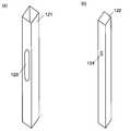
도 4는 본 실시예에 관한 상부 지주를 구성하는 (a) 외부 프레임과 (b) 슬라이드심의 사시도.
도 5는 본 발명의 변형예에 관한 선반의 사시도.
도 6은 본 발명의 변형예에 관한 선반의 사시도.1 is a shelf according to the present embodiment, in which (a) a shelf box is arranged up and down, (b) a form in which the connecting plate is rotated from the shape of (a), and (c) the shelf box is a step. Explanatory drawing which shows the shape change to the form arrange | positioned by the shape.
Figure 2 is a perspective view of a form in which the shelf box is arranged up and down in the shelf according to the present embodiment.
3 is a perspective view of a form in which a shelf is arranged in a step shape in the shelf according to the present embodiment.
Fig. 4 is a perspective view of (a) the outer frame and (b) the slide shim constituting the upper strut according to the present embodiment.
5 is a perspective view of a shelf according to a modification of the present invention.
6 is a perspective view of a shelf according to a modification of the present invention.
본 발명의 실시의 형태에 대해서 도 1 ~ 도 6을 이용하여 설명한다.Embodiments of the present invention will be described with reference to FIGS. 1 to 6.
실시예Example
도 1은 본 실시예에 관한 선반이 (a) 선반상자가 상하로 배치된 형태로부터 (c) 선반상자가 계단 모양으로 배치된 형태로 변형하는 모습을 나타내는 설명도이며, 도 2는 선반상자가 상하로 배치된 형태의 사시도, 도 3은 선반상자가 계단 모양으로 배치된 형태의 사시도이다. 상부 선반(10)은 상부 배판(11), 상부 배판(11)의 배면 양측에 마련된 상부 지주(12) 및 상부 선반상자(13)로 이루어진다. 상부 선반상자(13)는 상부 배판(11)의 전면에 수평으로 장착되어 있다. 상부 선반상자(13)는 상부 지주(12)의 하단으로부터 하부 지주(22)의 높이만큼 위쪽에 상부 선반상자(13)의 하단이 위치하도록 장착되어 있다. 또, 상부 배판(11)의 상부에는 끈을 통과시키기 위한 끈구멍(14)이 2개 마련되며, 끈(15)이 통과되어 있다. 하부 선반(20)은 하부 배판(21), 하부 배판(21)의 배면 양측에 마련된 하부 지주(22) 및 하부 선반상자(23)로 이루어진다. 하부 선반상자(23)는 하부 배판(21)의 전면 하단에 장착되어 있다. 하부 지주(22)는 내측이 공동(空洞)으로 되어 있다.1 is an explanatory view showing how the shelf according to the present embodiment is deformed from (a) the shelf box is arranged up and down from (c) the shelf box is arranged in a step shape, Figure 2 is a shelf box 3 is a perspective view of a form in which a shelf box is arranged in a step shape. The
연결판(30)은 상부 배판 접착부(31), 하부 배판 접착부(32) 및 연결부(33)로 이루어진다. 상부 배판 접착부(31)와 연결부(33)와의 경계 및 하부 배판 접착부(32)와 연결부(33)와의 경계는 각각 직선 모양이며, 연결판(30)은 각 경계선에서 절곡 가능하다. 상부 배판 접착부(31)는 상부 배판(11) 정면의 상부 선반상자(13)의 장착부의 아래쪽에, 하부 배판 접착부(32)는 하부 배판의 배면에, 각각 접착되어 있다. 연결부(33)와 상부 배판 접착부(31)와의 경계선은 상부 선반상자(13)의 장착위치 하단에 따르도록, 수평으로 배치되어 있다. 연결부(33)의 길이는 상부 선반상자(13)의 저면의 깊이와 같다. 또한, 본 실시예에서의 상부 배판(11), 상부 지주(12), 상부 선반상자(13), 하부 배판(21), 하부 지주(22), 하부 선반상자(23) 및 연결판(30)은 모두 두꺼운 종이로 이루어진다.The connecting
우선, 도 1의 (a) 및 도 2를 참조하면서, 선반상자가 상하로 배치된 형태에 대해서 설명한다. 연결판(30)을 연결부(33)와 하부 배판 접착부(32)와의 경계선에서는 절곡하지 않고, 연결부(33)와 상부 배판 접착부(31)와의 경계선에서 180° 절곡한다. 이것에 의해, 상부 배판(11)과 하부 배판(21)은 연결판(30)을 통하여 상하로 일렬로 배치되게 된다. 상부 지주(12)는 하부 지주(22)의 상부에 배치되기 때문에, 상부 지주(12)를 아래쪽으로 연장하고, 그 연장 부분(16)(도 1의 (a)의 사선 부분)을 하부 지주(22)의 내부에 수납함으로써, 상부 선반(10)을 하부 선반(20)과 안정적으로 연결할 수 있다. 따라서, 끈구멍(14)에 통과한 끈(15)에 의해, 선반 전체를 매달아 내릴 수 있다.First, with reference to FIGS. 1A and 2, a form in which shelf boxes are arranged up and down will be described. The connecting
무엇보다, 선반상자가 상하로 배치된 형태의 선반을 바닥 등의 수평면상에 배치했다고 해도, 하부 선반(20)은 하부 지주(22) 및 하부 선반상자(23)의 저면에 의해 유지되기 때문에, 안정성을 유지하는 것은 가능하다.Above all, even if the shelf of the form in which the shelf box is arranged up and down is placed on a horizontal surface such as a floor, since the
다음으로, 선반상자가 상하로 배치된 형태(도 1의 (a))로부터 계단 모양으로 배치된 형태(도 1의 (c))로 변형시키는 순서(도 1의 (b) 참조)를 설명한다.Next, the procedure (refer to FIG. 1 (b)) which deforms the shelf box from the form arrange | positioned up and down (FIG. 1 (a)) to the form arrange | positioned in step shape (FIG. 1 (c)) is shown. .
연결판(30)의, 연결부(33)와 상부 배판 접착부(31)와의 사이의 경계선의 절곡 각도를 180°로부터 작게 해 간다. 그 때, 상부 지주(12)의 연장 부분(16)은 원래로 되돌려 둔다. 동시에, 연결부(33)와 하부 배판 접착부(32)와의 경계선을 절곡하고, 하부 선반(20)가 상부 선반(10)의 전방으로 돌출하도록 한다.The bending angle of the boundary line between the
연결부(33)와 상부 배판 접착부(31)와의 경계선 및 연결부(33)와 하부 배판 접착부(32)와의 경계선에서의 절곡 각도가 모두 90°가 되면, 연결부(33)는 상부 배판(11) 및 하부 배판(21) 중 어느 하나에 대해서도 수직이 된다(도 1의 (c) 및 도 3 참조). 상술한 바와 같이, 연결부(33)와 상부 배판 접착부(31)와의 경계선은 상부 지주(12)의 하단으로부터 하부 지주(22)의 높이만큼 위쪽에 배치되어 있기 때문에, 하부 지주(22)의 하단과 상부 지주(12)의 하단의 높이는 동일하게 된다. 따라서, 하부 지주(22)를 바닥 등의 수평면상에 두면, 상부 지주(12)의 하단도 동일 수평면상에 안정적으로 얹어 놓이게 되어, 계단 모양의 선반을 수평면상에서 안정적으로 둘 수 있다. 또한, 본 실시예에서는 연결부(33)와 상부 배판 접착부(31)와의 경계선이 상부 선반상자(13)의 장착위치 하단에 따르도록 배치되어 있기 때문에, 연결부(33)와 상부 배판 접착부(31)와의 경계선에서의 절곡 각도가 90°가 되면, 상부 선반상자(13)의 저면이 연결부(33)상에 얹어 놓이게 된다.When the bending angle at the boundary between the connecting
다음으로, 본 실시예에 관한 선반에 있어서, 상부 지주(12)가 연장되는 구조에 대해서, 도 4를 이용하여 설명한다. 상부 지주(12)는 외부 프레임(121)과 슬라이드심(122)으로 이루어진다. 외부 프레임(121)의 내부는 공동이며, 측면에는 가늘고 긴 창(123)이 마련되어 있다. 슬라이드심(122)의 외치수는 외부 프레임(121)의 내치수보다 약간 작고, 손가락을 찔러 넣는 구멍(124)이 측면의 상부에 마련되어 있다. 슬라이드심(122)은 외부 프레임(121)의 내부에 창(123)과 구멍(124)이 동일 방향을 향하도록 수납되어 있다. 선반상자를 계단 모양으로 배치하는 구성에서는, 슬라이드심(122)은 완전하게 외부 프레임(121) 내부에 수납되어 있다. 선반상자를 상하로 배치하는 구성으로 변화시킬 때에는, 사용자는 손가락을 창(123)을 통하여 구멍(124)에 삽입하고, 구멍(124)을 창을 따라서 아래쪽으로 슬라이드시킨다. 이것에 의해, 슬라이드심(122)이 외부 프레임(121) 하단으로부터 아래쪽으로 노출하여, 상부 지주(12)의 길이가 연장된다. 이와 같이 하여 외부 프레임(121) 하단으로부터 노출한 슬라이드심(122)은 하부 지주(22) 내부에 수납되며, 상부 지주(12)와 하부 지주(22)가 연결된다.Next, in the shelf which concerns on a present Example, the structure in which the
본 발명은 상기 실시예에 한정되지 않고, 발명의 취지의 범위 내에서 변경이 허용된다. 예를 들면, 상기 실시예에서는 선반은 상하의 2개이지만, 3개 이상으로 할 수도 있다. 선반상자가 3개인 경우, 한가운데의 선반은 맨 위의 선반과의 관계에서는 하부 선반으로 할 수 있고, 맨 밑의 선반과의 관계에서는 상부 선반으로 할 수 있다.This invention is not limited to the said Example, A change is permissible within the scope of the invention. For example, in the said Example, although two shelves are upper and lower, it can also be three or more. In the case of three shelf boxes, the middle shelf can be a lower shelf in relation to the top shelf and an upper shelf in relation to the bottom shelf.
본 실시예에서는, 연결판(30)을 상부 배판 접착부(31), 하부 배판 접착부(32) 및 연결부(33)로부터 이루어지는 구성으로 했지만, 연결부(33)만으로 할 수도 있다. 그 경우, 연결부(33)를 상부 배판(11)이나 하부 배판(21)에 대해, 힌지 등을 이용하여 회동 가능하게 장착하면 된다.In the present embodiment, the connecting
또, 예를 들면, 본 실시예에서는 상부 선반(10)의 상부 선반상자(13)는, 연결부(33)와 상부 배판 접착부(31)와의 경계선에 따르는 위치에서 장착되어 있지만, 연결부(33)와 상부 배판 접착부(31)와의 경계선보다 위쪽에 상부 선반상자(13)를 장착하여도 된다(도 5 참조). 이 경우, 선반상자를 계단 모양으로 배치한 형태에서는, 상부 선반상자(13)는 연결판(30)의 연결부(33)상에 얹어 놓이지 않고, 연결부(33)로부터 조금 뜬 상태로 배치되게 된다. 또, 하부 배판 접착부(32)에 하부 배판(21)의 역할을 겸용시켜, 하부 선반상자(23)를 하부 배판 접착부(32)에 직접 장착하는 것도 가능하다. 또한, 선반상자는 직방체일 필요는 없으며, 측면을 사다리꼴로 하는 것도 가능하고(도 6 참조), 상부 지주(12), 하부 지주(22)의 형상도 도 2, 도 3에서는 직방체로서 나타냈지만, 삼각기둥이나 원기둥 등, 여러 가지 형태를 고려할 수 있다(도 6 참조). 상기 실시예에 관한 선반은 두꺼운 종이로 되어 있지만, 소재가 종이에 한정되는 것도 아니고, 플라스틱 등을 이용하는 것도 가능하다.For example, in this embodiment, although the
10 … 상부 선반11 … 상부 배판
12 … 상부 지주13 … 상부 선반상자
14 … 끈구멍15 … 끈
16 … 지주 연장 부분20 … 하부 선반
21 … 하부 배판22 … 하부 지주
23 … 하부 선반상자30 … 연결판
31 … 상부 배판 접착부32 … 하부 배판 접착부
33 … 연결부121 … 외부 프레임
122 … 슬라이드심123 … 창
124 … 구멍10 ...
12 ...
14. . string
16.
21 ... Lower back
23 ...
31 ... Upper back plate
33 ...
122...
124. hole
Claims (3)
Translated fromKorean복수의 선반상자가 상하로 일렬로 배치되는 제2 형태와의 사이에 변형 가능한 진열용 선반으로서,
상부 선반상자와, 상기 상부 선반상자를 전면(前面)에 유지하는 상부 배판(背板)을 가지는 상부 선반과,
하부 선반상자와, 상기 하부 선반상자를 전면에 유지하는 하부 배판을 가지는 하부 선반과,
상기 상부 선반상자의 하부 및 상기 하부 선반상자의 상부에서 상기 상부 선반과 상기 하부 선반을 연결하는 연결부재를 구비하고,
상기 연결부재는 상기 상부 선반 및 상기 하부 선반에 대한 장착부를 지점(支点)으로 하여 상하로 회동 가능하게 구성되며,
상기 연결부재를 회동시켜 상기 상부 배판 및 상기 하부 배판에 수직인 상태 또는 평행한 상태로 함으로써, 상기 제1 형태와 상기 제2 형태로 변형하는 것을 특징으로 하는 진열용 선반.The first form in which a plurality of shelf boxes are arranged in a staircase shape,
As a display shelf which can deform | transform between the 2nd form in which several shelf boxes are arrange | positioned up and down in line,
An upper shelf having an upper shelf box and an upper backboard for holding the upper shelf box at the front surface;
A lower shelf having a lower shelf box and a lower back plate for holding the lower shelf box at the front;
A connection member connecting the upper shelf and the lower shelf at a lower portion of the upper shelf box and an upper portion of the lower shelf box;
The connecting member is configured to be rotatable up and down by using a mounting portion for the upper shelf and the lower shelf as a point (支点),
And turning the connecting member into a state perpendicular to or parallel to the upper and lower back plates, thereby deforming into the first and second forms.
상기 상부 배판은 그 좌우 양측에 한 쌍의 상부 지주를 구비하고,
상기 하부 배판은 그 좌우 양측에 한 쌍의 하부 지주를 구비하며,
상기 상부 지주는 하부에서 신축 가능하게 구성되고,
상기 하부 지주는 상기 제2 형태로 변형시켰을 때에 상기 상부 지주의 연장 부분이 위쪽으로부터 진입 가능한 구멍부를 가지는 것을 특징으로 하는 진열용 선반.The method according to claim 1,
The upper backboard has a pair of upper posts on both left and right sides thereof,
The lower backboard has a pair of lower struts on both left and right sides thereof,
The upper strut is configured to be elastic at the bottom,
And said lower support has a hole portion through which an extended portion of said upper support enters from above when deformed into said second form.
상기 상부 지주는 외부 프레임과 그 내부에 수납된 슬라이드심(芯)으로 이루어지고, 이 외부 프레임의 일측면에는 창이 마련되며, 이 슬라이드심의 일측면에는 오목 모양의 손가락 넣음부가 마련되고, 이 손가락 넣음부를 상기 창 내에서 슬라이드시키는 것에 의해서 이 상부 지주가 신축 가능한 것을 특징으로 하는 진열용 선반.The method according to claim 2,
The upper strut consists of an outer frame and a slide shim housed therein, a window is provided on one side of the outer frame, and a concave finger recess is provided on one side of the slide shim. The upper shelf is stretchable by sliding a part in the window.
Applications Claiming Priority (3)
| Application Number | Priority Date | Filing Date | Title |
|---|---|---|---|
| JPJP-P-2010-113158 | 2010-05-17 | ||
| JP2010113158 | 2010-05-17 | ||
| PCT/JP2011/060972WO2011145510A1 (en) | 2010-05-17 | 2011-05-12 | Display case |
Publications (2)
| Publication Number | Publication Date |
|---|---|
| KR20130036254Atrue KR20130036254A (en) | 2013-04-11 |
| KR101435735B1 KR101435735B1 (en) | 2014-08-28 |
Family
ID=44991616
Family Applications (1)
| Application Number | Title | Priority Date | Filing Date |
|---|---|---|---|
| KR1020127032902AExpired - Fee RelatedKR101435735B1 (en) | 2010-05-17 | 2011-05-12 | Display rack |
Country Status (6)
| Country | Link |
|---|---|
| US (1) | US8939091B2 (en) |
| JP (2) | JP5155493B2 (en) |
| KR (1) | KR101435735B1 (en) |
| CN (1) | CN102905582B (en) |
| TW (1) | TWI524868B (en) |
| WO (1) | WO2011145510A1 (en) |
Cited By (1)
| Publication number | Priority date | Publication date | Assignee | Title |
|---|---|---|---|---|
| CN110811237A (en)* | 2019-12-13 | 2020-02-21 | 株洲瑞尔泰机电科技有限公司 | Model display device for selling electromechanical products |
Families Citing this family (6)
| Publication number | Priority date | Publication date | Assignee | Title |
|---|---|---|---|---|
| GB2511521B (en)* | 2013-03-05 | 2016-07-27 | Ds Smith Plastics Ltd | Product presenter |
| US10912399B2 (en)* | 2017-02-17 | 2021-02-09 | Mathew Cianchino | Stands to hold model objects |
| US10888180B2 (en)* | 2019-06-03 | 2021-01-12 | International Paper Company | Quick setup hutch unit |
| JP7243503B2 (en)* | 2019-07-16 | 2023-03-22 | 大日本印刷株式会社 | Display tool |
| WO2023154932A1 (en)* | 2022-02-14 | 2023-08-17 | Kovhr Inc. | Organizational shell |
| US20240349895A1 (en)* | 2023-04-18 | 2024-10-24 | Silicate Studio Home, LLC | Shelf system for vertical mounts |
Family Cites Families (36)
| Publication number | Priority date | Publication date | Assignee | Title |
|---|---|---|---|---|
| US303783A (en)* | 1884-08-19 | Chest for tools | ||
| US744855A (en)* | 1903-07-01 | 1903-11-24 | Gustav Becker | Box. |
| US939807A (en)* | 1909-05-07 | 1909-11-09 | Jerome B Rice Seed Company | Packing and display receptacle. |
| US1541211A (en)* | 1923-11-22 | 1925-06-09 | Lewis E Ford | Tool receptacle or carrier |
| US1770618A (en)* | 1927-05-13 | 1930-07-15 | Brooks Bank Note Company | Display box |
| US1731878A (en)* | 1928-05-25 | 1929-10-15 | Einson Freeman Co Inc | Packing and display container |
| US1758726A (en)* | 1929-01-19 | 1930-05-13 | Herbert C Webb | Combined shelf and folding table |
| US1929615A (en)* | 1931-01-30 | 1933-10-10 | Arnold J Tanner | Packing and display container for merchandise |
| US1955769A (en)* | 1931-08-22 | 1934-04-24 | American Can Co | Display device |
| US2772003A (en)* | 1952-10-28 | 1956-11-27 | Coats & Clark | Display cabinet |
| US4716841A (en)* | 1982-09-07 | 1988-01-05 | The Mead Corporation | Shelving unit |
| US5590796A (en)* | 1995-01-17 | 1997-01-07 | Herman; Richard J. | Multiple configuration produce stand |
| JP2706913B2 (en) | 1995-11-29 | 1998-01-28 | 株式会社タナカヤ | Standing combined use display shelf |
| US5706959A (en)* | 1996-10-03 | 1998-01-13 | Arrow Art Finishers, Inc. | Display structure with lock-in trays |
| US6053114A (en)* | 1996-11-19 | 2000-04-25 | Villanueva; Robert | Adjustable storage rack |
| US5746139A (en)* | 1996-11-19 | 1998-05-05 | Villanueva; Robert | Adjustable storage rack |
| JPH11275967A (en)* | 1998-03-30 | 1999-10-12 | Swan Moving Wall Kk | Flower stand |
| TW366745U (en)* | 1999-01-22 | 1999-08-11 | Wen-Shan Ke | Computer desk structure with lifting function |
| US6321663B1 (en)* | 1999-03-26 | 2001-11-27 | James A. Rogers | Adjustable display shelf system |
| US6543796B1 (en)* | 1999-11-19 | 2003-04-08 | Kenneth R. Johnson | Combined desk and luggage carrier |
| FR2810521B1 (en)* | 2000-06-27 | 2002-09-13 | Larbaletier Sa | DISPLAY OF GOODS |
| JP3786591B2 (en)* | 2001-08-29 | 2006-06-14 | アイベックスアンドリムズ株式会社 | Display device that can be used properly for hanging and placing |
| US20050077695A1 (en)* | 2002-02-14 | 2005-04-14 | Lanny Sherer | Container with adjustable legs |
| US6942108B2 (en)* | 2002-06-19 | 2005-09-13 | Anderson News Company | Display rack |
| GB0218529D0 (en)* | 2002-08-09 | 2002-09-18 | Lighthouse Display Internat Lt | Display device and blank therfor |
| US7111735B2 (en)* | 2004-10-01 | 2006-09-26 | Sonoco Development, Inc. | Base for post in post product packaging and display system |
| US7111743B1 (en)* | 2005-01-26 | 2006-09-26 | Poptech Limited | Foldable stepped display stands |
| JP4854974B2 (en)* | 2005-03-14 | 2012-01-18 | エヌカント株式会社 | Display shelf |
| US20060249059A1 (en)* | 2005-04-05 | 2006-11-09 | Michelle Gagne | Multi-layer collapsible portable folding display table |
| JP3113539U (en)* | 2005-06-10 | 2005-09-08 | 日本臓器製薬株式会社 | Display tools |
| JP3115173U (en)* | 2005-07-28 | 2005-11-04 | エヌカント株式会社 | Product display tools |
| US7537121B2 (en)* | 2006-02-16 | 2009-05-26 | Sonoco Development, Inc. | Accordion product display container |
| FR2908613A1 (en)* | 2006-11-22 | 2008-05-23 | Stephane Fortier | Telescopic storage device for use with container e.g. trunk type, has storage planes and telescopic supports fixed on base of container, where supports are folded and storage planes are lowered and brought together by reverse action of user |
| US20080169254A1 (en)* | 2007-01-17 | 2008-07-17 | Govrik Christopher D | Adjustable shower caddy |
| WO2008127686A1 (en)* | 2007-04-13 | 2008-10-23 | Alexander Virvo | Folding shelf display |
| US7845656B2 (en)* | 2007-05-03 | 2010-12-07 | Thompson/Mcmahon Industries Llc | Drywall cart |
- 2011
- 2011-05-12KRKR1020127032902Apatent/KR101435735B1/ennot_activeExpired - Fee Related
- 2011-05-12JPJP2012515855Apatent/JP5155493B2/enactiveActive
- 2011-05-12WOPCT/JP2011/060972patent/WO2011145510A1/enactiveApplication Filing
- 2011-05-12USUS13/698,193patent/US8939091B2/ennot_activeExpired - Fee Related
- 2011-05-12CNCN201180024537.6Apatent/CN102905582B/ennot_activeExpired - Fee Related
- 2011-05-13TWTW100116769Apatent/TWI524868B/ennot_activeIP Right Cessation
- 2012
- 2012-12-06JPJP2012266859Apatent/JP5562402B2/enactiveActive
Cited By (1)
| Publication number | Priority date | Publication date | Assignee | Title |
|---|---|---|---|---|
| CN110811237A (en)* | 2019-12-13 | 2020-02-21 | 株洲瑞尔泰机电科技有限公司 | Model display device for selling electromechanical products |
Also Published As
| Publication number | Publication date |
|---|---|
| JP5562402B2 (en) | 2014-07-30 |
| JP2013046865A (en) | 2013-03-07 |
| KR101435735B1 (en) | 2014-08-28 |
| US8939091B2 (en) | 2015-01-27 |
| JPWO2011145510A1 (en) | 2013-07-22 |
| CN102905582B (en) | 2015-01-07 |
| TWI524868B (en) | 2016-03-11 |
| WO2011145510A1 (en) | 2011-11-24 |
| CN102905582A (en) | 2013-01-30 |
| JP5155493B2 (en) | 2013-03-06 |
| TW201143684A (en) | 2011-12-16 |
| US20130062298A1 (en) | 2013-03-14 |
Similar Documents
| Publication | Publication Date | Title |
|---|---|---|
| KR20130036254A (en) | Display case | |
| US7900784B1 (en) | Configurable retail displays | |
| US6758352B2 (en) | Collapsible display structure and shelf module for use therewith | |
| US8579122B2 (en) | Modular system for display | |
| WO2015180406A1 (en) | Stacked display container and display rack for products | |
| KR20120055567A (en) | Packaging container | |
| RU2684334C1 (en) | Display for goods displaying (versions) | |
| US20130284638A1 (en) | Packaging and Supporting Device for Liquid Crystal Display Module | |
| CN202003614U (en) | Display equipment and fixed bracket for same | |
| US20170215603A1 (en) | Display fixture divider | |
| RU2713983C1 (en) | Display for displaying goods (versions) | |
| JP3182009U (en) | Product display tools | |
| JP5677022B2 (en) | Product display stand | |
| CN217792291U (en) | Multifunctional display rack | |
| JP6624420B2 (en) | Display fixtures | |
| CN214678415U (en) | Changeable show rack | |
| JP6482055B2 (en) | Storage box combined with stage box | |
| KR200174368Y1 (en) | A show box of goods exchangeable of the advertisement plate | |
| JP2020022583A (en) | Support structure for standing body | |
| KR20090031112A (en) | Prefab display stands | |
| KR20110008580U (en) | Wheel brackets of shelves and display racks | |
| KR20120053118A (en) | Frame member for prefabricated interior angle rack or display stand and frame member set including the same | |
| CN208676812U (en) | A kind of combined type exhibition platform | |
| JP2015211802A (en) | Product display shelf members and product display fixtures | |
| JP3104017U (en) | Display device |
Legal Events
| Date | Code | Title | Description |
|---|---|---|---|
| PA0105 | International application | St.27 status event code:A-0-1-A10-A15-nap-PA0105 | |
| A201 | Request for examination | ||
| P11-X000 | Amendment of application requested | St.27 status event code:A-2-2-P10-P11-nap-X000 | |
| P13-X000 | Application amended | St.27 status event code:A-2-2-P10-P13-nap-X000 | |
| PA0201 | Request for examination | St.27 status event code:A-1-2-D10-D11-exm-PA0201 | |
| P11-X000 | Amendment of application requested | St.27 status event code:A-2-2-P10-P11-nap-X000 | |
| P13-X000 | Application amended | St.27 status event code:A-2-2-P10-P13-nap-X000 | |
| PG1501 | Laying open of application | St.27 status event code:A-1-1-Q10-Q12-nap-PG1501 | |
| E902 | Notification of reason for refusal | ||
| PE0902 | Notice of grounds for rejection | St.27 status event code:A-1-2-D10-D21-exm-PE0902 | |
| E13-X000 | Pre-grant limitation requested | St.27 status event code:A-2-3-E10-E13-lim-X000 | |
| P11-X000 | Amendment of application requested | St.27 status event code:A-2-2-P10-P11-nap-X000 | |
| P13-X000 | Application amended | St.27 status event code:A-2-2-P10-P13-nap-X000 | |
| E701 | Decision to grant or registration of patent right | ||
| PE0701 | Decision of registration | St.27 status event code:A-1-2-D10-D22-exm-PE0701 | |
| GRNT | Written decision to grant | ||
| PR0701 | Registration of establishment | St.27 status event code:A-2-4-F10-F11-exm-PR0701 | |
| PR1002 | Payment of registration fee | St.27 status event code:A-2-2-U10-U12-oth-PR1002 Fee payment year number:1 | |
| PG1601 | Publication of registration | St.27 status event code:A-4-4-Q10-Q13-nap-PG1601 | |
| PR1001 | Payment of annual fee | St.27 status event code:A-4-4-U10-U11-oth-PR1001 Fee payment year number:4 | |
| FPAY | Annual fee payment | Payment date:20180530 Year of fee payment:5 | |
| PR1001 | Payment of annual fee | St.27 status event code:A-4-4-U10-U11-oth-PR1001 Fee payment year number:5 | |
| PC1903 | Unpaid annual fee | St.27 status event code:A-4-4-U10-U13-oth-PC1903 Not in force date:20190823 Payment event data comment text:Termination Category : DEFAULT_OF_REGISTRATION_FEE | |
| PC1903 | Unpaid annual fee | St.27 status event code:N-4-6-H10-H13-oth-PC1903 Ip right cessation event data comment text:Termination Category : DEFAULT_OF_REGISTRATION_FEE Not in force date:20190823 |