KR20130029202A - Lighting device - Google Patents
Lighting deviceDownload PDFInfo
- Publication number
- KR20130029202A KR20130029202AKR1020110092453AKR20110092453AKR20130029202AKR 20130029202 AKR20130029202 AKR 20130029202AKR 1020110092453 AKR1020110092453 AKR 1020110092453AKR 20110092453 AKR20110092453 AKR 20110092453AKR 20130029202 AKR20130029202 AKR 20130029202A
- Authority
- KR
- South Korea
- Prior art keywords
- light
- light source
- light guide
- guide unit
- present
- Prior art date
- Legal status (The legal status is an assumption and is not a legal conclusion. Google has not performed a legal analysis and makes no representation as to the accuracy of the status listed.)
- Ceased
Links
Images


Classifications
- F—MECHANICAL ENGINEERING; LIGHTING; HEATING; WEAPONS; BLASTING
- F21—LIGHTING
- F21V—FUNCTIONAL FEATURES OR DETAILS OF LIGHTING DEVICES OR SYSTEMS THEREOF; STRUCTURAL COMBINATIONS OF LIGHTING DEVICES WITH OTHER ARTICLES, NOT OTHERWISE PROVIDED FOR
- F21V19/00—Fastening of light sources or lamp holders
- F21V19/0075—Fastening of light sources or lamp holders of tubular light sources, e.g. ring-shaped fluorescent light sources
- F—MECHANICAL ENGINEERING; LIGHTING; HEATING; WEAPONS; BLASTING
- F21—LIGHTING
- F21V—FUNCTIONAL FEATURES OR DETAILS OF LIGHTING DEVICES OR SYSTEMS THEREOF; STRUCTURAL COMBINATIONS OF LIGHTING DEVICES WITH OTHER ARTICLES, NOT OTHERWISE PROVIDED FOR
- F21V7/00—Reflectors for light sources
- F21V7/0008—Reflectors for light sources providing for indirect lighting
- F—MECHANICAL ENGINEERING; LIGHTING; HEATING; WEAPONS; BLASTING
- F21—LIGHTING
- F21V—FUNCTIONAL FEATURES OR DETAILS OF LIGHTING DEVICES OR SYSTEMS THEREOF; STRUCTURAL COMBINATIONS OF LIGHTING DEVICES WITH OTHER ARTICLES, NOT OTHERWISE PROVIDED FOR
- F21V1/00—Shades for light sources, i.e. lampshades for table, floor, wall or ceiling lamps
- F21V1/14—Covers for frames; Frameless shades
- F—MECHANICAL ENGINEERING; LIGHTING; HEATING; WEAPONS; BLASTING
- F21—LIGHTING
- F21V—FUNCTIONAL FEATURES OR DETAILS OF LIGHTING DEVICES OR SYSTEMS THEREOF; STRUCTURAL COMBINATIONS OF LIGHTING DEVICES WITH OTHER ARTICLES, NOT OTHERWISE PROVIDED FOR
- F21V19/00—Fastening of light sources or lamp holders
- F21V19/001—Fastening of light sources or lamp holders the light sources being semiconductors devices, e.g. LEDs
- F—MECHANICAL ENGINEERING; LIGHTING; HEATING; WEAPONS; BLASTING
- F21—LIGHTING
- F21V—FUNCTIONAL FEATURES OR DETAILS OF LIGHTING DEVICES OR SYSTEMS THEREOF; STRUCTURAL COMBINATIONS OF LIGHTING DEVICES WITH OTHER ARTICLES, NOT OTHERWISE PROVIDED FOR
- F21V5/00—Refractors for light sources
- F21V5/04—Refractors for light sources of lens shape
- F—MECHANICAL ENGINEERING; LIGHTING; HEATING; WEAPONS; BLASTING
- F21—LIGHTING
- F21V—FUNCTIONAL FEATURES OR DETAILS OF LIGHTING DEVICES OR SYSTEMS THEREOF; STRUCTURAL COMBINATIONS OF LIGHTING DEVICES WITH OTHER ARTICLES, NOT OTHERWISE PROVIDED FOR
- F21V7/00—Reflectors for light sources
- F—MECHANICAL ENGINEERING; LIGHTING; HEATING; WEAPONS; BLASTING
- F21—LIGHTING
- F21V—FUNCTIONAL FEATURES OR DETAILS OF LIGHTING DEVICES OR SYSTEMS THEREOF; STRUCTURAL COMBINATIONS OF LIGHTING DEVICES WITH OTHER ARTICLES, NOT OTHERWISE PROVIDED FOR
- F21V7/00—Reflectors for light sources
- F21V7/0091—Reflectors for light sources using total internal reflection
- G—PHYSICS
- G02—OPTICS
- G02B—OPTICAL ELEMENTS, SYSTEMS OR APPARATUS
- G02B6/00—Light guides; Structural details of arrangements comprising light guides and other optical elements, e.g. couplings
- G02B6/0001—Light guides; Structural details of arrangements comprising light guides and other optical elements, e.g. couplings specially adapted for lighting devices or systems
- G02B6/0005—Light guides; Structural details of arrangements comprising light guides and other optical elements, e.g. couplings specially adapted for lighting devices or systems the light guides being of the fibre type
- G02B6/001—Light guides; Structural details of arrangements comprising light guides and other optical elements, e.g. couplings specially adapted for lighting devices or systems the light guides being of the fibre type the light being emitted along at least a portion of the lateral surface of the fibre
- F—MECHANICAL ENGINEERING; LIGHTING; HEATING; WEAPONS; BLASTING
- F21—LIGHTING
- F21K—NON-ELECTRIC LIGHT SOURCES USING LUMINESCENCE; LIGHT SOURCES USING ELECTROCHEMILUMINESCENCE; LIGHT SOURCES USING CHARGES OF COMBUSTIBLE MATERIAL; LIGHT SOURCES USING SEMICONDUCTOR DEVICES AS LIGHT-GENERATING ELEMENTS; LIGHT SOURCES NOT OTHERWISE PROVIDED FOR
- F21K9/00—Light sources using semiconductor devices as light-generating elements, e.g. using light-emitting diodes [LED] or lasers
- F21K9/20—Light sources comprising attachment means
- F21K9/23—Retrofit light sources for lighting devices with a single fitting for each light source, e.g. for substitution of incandescent lamps with bayonet or threaded fittings
- F21K9/232—Retrofit light sources for lighting devices with a single fitting for each light source, e.g. for substitution of incandescent lamps with bayonet or threaded fittings specially adapted for generating an essentially omnidirectional light distribution, e.g. with a glass bulb
- F—MECHANICAL ENGINEERING; LIGHTING; HEATING; WEAPONS; BLASTING
- F21—LIGHTING
- F21K—NON-ELECTRIC LIGHT SOURCES USING LUMINESCENCE; LIGHT SOURCES USING ELECTROCHEMILUMINESCENCE; LIGHT SOURCES USING CHARGES OF COMBUSTIBLE MATERIAL; LIGHT SOURCES USING SEMICONDUCTOR DEVICES AS LIGHT-GENERATING ELEMENTS; LIGHT SOURCES NOT OTHERWISE PROVIDED FOR
- F21K9/00—Light sources using semiconductor devices as light-generating elements, e.g. using light-emitting diodes [LED] or lasers
- F21K9/60—Optical arrangements integrated in the light source, e.g. for improving the colour rendering index or the light extraction
- F21K9/61—Optical arrangements integrated in the light source, e.g. for improving the colour rendering index or the light extraction using light guides
- F—MECHANICAL ENGINEERING; LIGHTING; HEATING; WEAPONS; BLASTING
- F21—LIGHTING
- F21Y—INDEXING SCHEME ASSOCIATED WITH SUBCLASSES F21K, F21L, F21S and F21V, RELATING TO THE FORM OR THE KIND OF THE LIGHT SOURCES OR OF THE COLOUR OF THE LIGHT EMITTED
- F21Y2115/00—Light-generating elements of semiconductor light sources
- F21Y2115/10—Light-emitting diodes [LED]
- G—PHYSICS
- G02—OPTICS
- G02B—OPTICAL ELEMENTS, SYSTEMS OR APPARATUS
- G02B6/00—Light guides; Structural details of arrangements comprising light guides and other optical elements, e.g. couplings
- G02B6/0001—Light guides; Structural details of arrangements comprising light guides and other optical elements, e.g. couplings specially adapted for lighting devices or systems
- G02B6/0011—Light guides; Structural details of arrangements comprising light guides and other optical elements, e.g. couplings specially adapted for lighting devices or systems the light guides being planar or of plate-like form
- G02B6/0013—Means for improving the coupling-in of light from the light source into the light guide
- G02B6/0015—Means for improving the coupling-in of light from the light source into the light guide provided on the surface of the light guide or in the bulk of it
- G02B6/0018—Redirecting means on the surface of the light guide
Landscapes
- Engineering & Computer Science (AREA)
- General Engineering & Computer Science (AREA)
- Physics & Mathematics (AREA)
- General Physics & Mathematics (AREA)
- Optics & Photonics (AREA)
- Planar Illumination Modules (AREA)
- Non-Portable Lighting Devices Or Systems Thereof (AREA)
Abstract
Description
Translated fromKorean실시예는 조명 장치에 관한 것이다.Embodiments relate to a lighting device.
발광 다이오드(LED)는 전기 에너지를 빛으로 변환하는 반도체 소자의 일종이다. 발광 다이오드는 형광등, 백열등 등 기존의 광원에 비해 저소비전력, 반영구적인 수명, 빠른 응답속도, 안전성, 환경친화성의 장점을 가진다. 이에 기존의 광원을 발광 다이오드로 대체하기 위한 많은 연구가 진행되고 있으며, 이미 발광 다이오드는 실내외에서 사용되는 각종 액정표시장치, 전광판, 가로등 등의 조명 장치의 광원으로서 사용이 증가되고 있는 추세이다.Light emitting diodes (LEDs) are a type of semiconductor device that converts electrical energy into light. Light emitting diodes have the advantages of low power consumption, semi-permanent life, fast response speed, safety and environmental friendliness compared to conventional light sources such as fluorescent and incandescent lamps. Accordingly, many researches have been conducted to replace the existing light source with light emitting diodes, and light emitting diodes have been increasingly used as light sources for lighting devices such as liquid crystal display devices, electronic displays, and street lights.
특히, 조명 장치 광원으로서 백색 LED 발광 장치의 사용이 증가하고 있는데, 청색 LED 칩과 황색 및 적색 형광체의 조합을 사용한 장치가 사용되고 있다. 청색 LED 칩으로부터 나온 청색광의 일부는 황색 형광체 및 적색 형과체를 여기하여 형광체로부터 발생되는 황색 및 적색광과 LED 로부터 발생되는 청색광이 혼색되어 연색성이 좋은 백색광을 발하게 된다.In particular, the use of a white LED light emitting device is increasing as a lighting device light source, and a device using a combination of a blue LED chip and a yellow and red phosphor is used. Some of the blue light emitted from the blue LED chip excites the yellow phosphor and the red fluorescent substance, and the yellow and red light generated from the phosphor and the blue light generated from the LED are mixed to give good color rendering.
그러나, 이러한 황색 및 적색 형광체를 사용한 백색 LED 발광장치는, 전체 휘도가 낮고 효율이 떨어지는 문제점이 있다.However, a white LED light emitting device using such yellow and red phosphors has a problem that the overall luminance is low and the efficiency is low.
본 발명의 실시예는 빛의 경로를 안내하는 조명 장치를 제공하기 위한 것이다.An embodiment of the present invention is to provide a lighting device for guiding a path of light.
본 발명의 다른 실시예는 후배광이 우수한 조명 장치를 제공하기 위한 것이다.Another embodiment of the present invention is to provide a lighting device having excellent post-light distribution.
상기와 같은 본 발명의 과제를 해결하기 위해 일부를 반사하는 반사부를 더 포함한다.In order to solve the problems of the present invention as described above further comprises a reflecting portion reflecting.
본 발명의 실시예에 따르면, 빛의 손실 없이 빛의 방출지점이 이동된 조명 장치를 얻을 수 있다.According to the embodiment of the present invention, it is possible to obtain a lighting device in which the emission point of the light is moved without losing the light.
또한, 본 발명의 실시예에 따르면, 표면 실장된 발광 소자를 이용하여 후배광이 우수한 조명 장치를 얻을 수 있다.In addition, according to the embodiment of the present invention, it is possible to obtain a lighting device excellent in the rear light distribution by using the surface-mounted light emitting device.
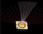
도 1(a)는 LED 광원을 나타내는 평면도이다.
도 1(b) 및 도 1(c)는 LED 광원의 진행방향을 개략적으로 나타내는 사시도 및 정면도이다.
도 2 는 도 1(a) 내지 도 1(c)에 도시된 LED 광원의 배광 분포의 시뮬레이션 결과를 나타낸다.
도 3은 본 발명의 실시예에 따른 조명 장치를 나타내는 사시도이다.
도 4(a) 내지 도 4(c)는 본 발명의 실시예에 따른 조명 장치에 의한 빛의 진행 방향을 나타내는 정면도이다.
도 5는 본 발명의 실시예에 따란 조명 장치에 의한 빛의 진행 방향의 시뮬레이션 결과를 나타낸다.
도 6은 본 발명의 다른 실시예에 의한 조명 장치의 정면도이다.
도 7은 본 발명의 다른 실시예에 의한 조명 장치의 빛의 진행 방향을 간략하게 나타낸 정면도이다.
도 8은 본 발명의 다른 실시예에 의한 조명 장치의 빛의 진행 방향을 간략하게 나타낸 정면도이다.
도 9는 본 발명의 다른 실시예에 의한 조명 장치의 사시도이다.
도 10a은 본 발명의 다른 실시예에 의한 조명 장치의 단면도이다.
도 10b는 도 10a에 도시된 조명 장치의 수치를 나타낸 표이다.
도 11은 본 발명의 다른 실시예에 의한 조명 장치의 광 가이드부 및 반사부에 대한 시뮬레이션 결과를 나타낸다.
도 12는 본 발명의 다른 실시예에 의한 조명 장치의 빛의 진행 방향을 간략하게 나타낸 정면도이다.
도 13은 본 발명의 다른 실시예에 의한 조명 장치의 커버부를 나타내는 정면도이다.
도 14는 본 발명의 다른 실시예에 의한 배광 분포의 시뮬레이션 결과를 나타낸다.Fig. 1A is a plan view of the LED light source.
1 (b) and 1 (c) are a perspective view and a front view schematically showing the traveling direction of the LED light source.
FIG. 2 shows simulation results of light distribution distribution of the LED light source shown in FIGS. 1A to 1C.
3 is a perspective view showing a lighting apparatus according to an embodiment of the present invention.
4 (a) to 4 (c) are front views showing the traveling direction of light by the lighting apparatus according to the embodiment of the present invention.
5 shows a simulation result of the traveling direction of light by the lighting apparatus according to an embodiment of the present invention.
6 is a front view of a lighting apparatus according to another embodiment of the present invention.
7 is a front view briefly showing a traveling direction of light of the lighting apparatus according to another embodiment of the present invention.
8 is a front view briefly showing a traveling direction of light of the lighting apparatus according to another embodiment of the present invention.
9 is a perspective view of a lighting apparatus according to another embodiment of the present invention.
10A is a cross-sectional view of a lighting apparatus according to another embodiment of the present invention.
FIG. 10B is a table showing numerical values of the lighting apparatus shown in FIG. 10A.
11 shows simulation results of the light guide part and the reflecting part of the lighting apparatus according to another embodiment of the present invention.
12 is a front view briefly showing a traveling direction of light of the lighting apparatus according to another embodiment of the present invention.
13 is a front view showing a cover of the lighting apparatus according to another embodiment of the present invention.
14 shows simulation results of light distribution distribution according to another embodiment of the present invention.
이하 본 발명의 실시예에 대하여 첨부한 도면을 참조하여 상세하게 설명하기로 한다. 다만, 첨부된 도면은 본 발명의 내용을 보다 쉽게 개시하기 위하여 설명되는 것일 뿐, 본 발명의 범위가 첨부된 도면의 범위로 한정되는 것이 아님은 이 기술분야의 통상의 지식을 가진 자라면 용이하게 알 수 있을 것이다.Hereinafter, embodiments of the present invention will be described in detail with reference to the accompanying drawings. It is to be understood, however, that the appended drawings illustrate the present invention in order to more easily explain the present invention, and the scope of the present invention is not limited thereto. You will know.
또한 각 구성요소의 상 또는 아래에 대한 기준은 도면을 기준으로 설명한다.도면에서 각층의 두께나 크기는 설명의 편의 및 명확성을 위하여 과장되거나 생략되거나 또는 개략적으로 도시되었다. 또한 각 구성요소의 크기는 실제크기를 전적으로 반영하는 것은 아니다.In addition, the reference to the top or bottom of each component will be described with reference to the drawings. In the drawings, the thickness or size of each layer is exaggerated, omitted, or schematically illustrated for convenience and clarity. In addition, the size of each component does not necessarily reflect the actual size.
본 발명에 따른 실시 예의 설명에 있어서, 어느 한 element가 다른 element의 " 상(위) 또는 하(아래)(on or under)"에 형성되는 것으로 기재되는 경우에 있어, 상(위) 또는 하(아래)(on or under)는 두 개의 element가 서로 직접(directly)접촉되거나 하나 이상의 다른 element가 상기 두 element사이에 배치되어(indirectly) 형성되는 것을 모두 포함한다. 또한 "상(위) 또는 하(아래)(on or under)" 으로 표현되는 경우 하나의 element를 기준으로 위쪽 방향뿐만 아니라 아래쪽 방향의 의미도 포함할 수 있다.In the description of embodiments according to the present invention, it is to be understood that where an element is described as being formed "on or under" another element, On or under includes both the two elements being directly in direct contact with each other or one or more other elements being indirectly formed between the two elements. In addition, when expressed as "on" or "under", it may include the meaning of the downward direction as well as the upward direction based on one element.
또한, 명세서 전체에서, 어떤 부분이 다른 부분과 "연결" 되어 있다고 할 때, 이는 "직접적으로 연결" 되어 있는 경우뿐 아니라, 그 중간에 다른 소자를 사이에 두고 "전기적으로 연결" 되어 있는 경우도 포함한다. 또한 어떤 부분이 어떤 구성요소를 "포함"한다고 할 때, 이는 특별히 반대되는 기재가 없는 한 다른 구성요소를 제외하는 것이 아니라 다른 구성요소를 더 포함할 수 있는 것을 의미한다.In addition, throughout the specification, when a part is "connected" to another part, it is not only "directly connected", but also "electrically connected" with another element in between. Include. Also, when an element is referred to as "comprising ", it means that it can include other elements as well, without departing from the other elements unless specifically stated otherwise.
도 1(a) 내지 도 1(c)는 본 발명의 실시예에 이용되는 LED 광원을 나타낸다.1 (a) to 1 (c) show an LED light source used in an embodiment of the present invention.
도 1(a) 내지 도 1(c)를 참조하면, 발광 기판에 LED 칩이 실장된 COB(Chip On Board) 타입 또는 SMD(Surface Molding Device) 방식의 발광소자인 경우로 LED칩위에 형광체를 도포하여 원하는 색의 광원을 만들 수 있다.1 (a) to 1 (c), the phosphor is coated on the LED chip in the case of a COB (Chip On Board) type or SMD (Surface Molding Device) type light emitting device in which the LED chip is mounted on the light emitting substrate. You can make a light source of the desired color.
도 2는 도 1(a) 내지 도 1(c)에 도시된 LED 광원의 배광 분포에 대한 시뮬레이션 결과를 나타낸다.FIG. 2 shows simulation results of light distribution distribution of the LED light source shown in FIGS. 1A to 1C.
도 1(a) 내지 도 1(c) 및 도 2를 참조하면, 발광 소자에서 방출된 빛은 전방으로만 빛이 분포되며, 후배광은 거의 없다.1 (a) to 1 (c) and FIG. 2, the light emitted from the light emitting device is only distributed in the forward direction, and there is almost no rear light distribution.
따라서, 본 발명의 실시예에서는 광원을 이용하여 후배광을 구현한 조명 장치에 관하여 설명한다. 먼저, 광원이 외부로 방출되는 빛의 경로를 안내하는 가이드부를 포함하는 조명 장치에 관하여 설명한다.
Therefore, the embodiment of the present invention will be described with respect to a lighting device that implements the rear light distribution using a light source. First, a lighting apparatus including a guide unit for guiding a path of light from which a light source is emitted to the outside will be described.
<가이드부를 포함하는 조명 장치><Lighting device including guide part>
도 3은 본 발명의 실시예에 따라, 광 가이드부를 포함하는 조명 장치를 나타내는 사시도이다.3 is a perspective view illustrating a lighting device including a light guide unit according to an embodiment of the present invention.
도 3을 참조하면, 본 발명의 실시예에 따른 조명 장치는, 기판(1)과 기판(1)위에 배치된 광원(10), 상기 기판(1)위에 형성되고 상기 LED(10) 광원을 감싸는 광 가이드부(20)를 포함한다.Referring to FIG. 3, a lighting device according to an embodiment of the present invention includes a
상기 기판(1)은 PCB 등의 기판일 수 있다.The
상기 광원(10)은 MCP타입의 발광 소자 패키지일 수 있으며, 단일 LED칩에 형광체를 도포한 광원일 수 있다.The
상기 광 가이드부(20)는 상기 광원(10)의 위에 배치된다. 도 3에 도시된 바와 같이, 상기 광 가이드부(20)는 상기 광원(10)의 상측에 원기둥 형태로 형성될 수 있으며, 상기 광 가이드 부(20)의 지름은 상기 광원(10)의 크기와 동일하거나 약간 더 크게 형성될 수 있다. 상기 광원(10)의 밑면은 반드시 원 형태일 필요는 없으며, 구현하고자 하는 배광 분포에 따라 타원이거나 다각형일 수도 있다.The
상기 광 가이드부(20)는 빛이 투과될 수 있도록 투명한 소재로 이루어지며, 발광 소자에서 방출된 빛이 상기 광 가이드부(20)에 의하여 상기 광 가이드부(20) 내측으로 전반사 될 수 있도록, 굴절률이 공기보다 커야한다.The
도 4(a) 내지 도 4(c)는 광 가이드부(20)가 포함된 조명 장치에서 빛이 진행하는 방향을 나타낸다.4 (a) to 4 (c) show a direction in which light travels in the lighting apparatus including the
이하, 도 3 및 도 4(a) 내지 도 4(c)를 참조하여 발광 소자에서 방출된 빛의 진행에 관하여 설명한다.Hereinafter, the progress of light emitted from the light emitting device will be described with reference to FIGS. 3 and 4A to 4C.
도 3 및 도 4(b)에 도시된 바와 같이, 광원(10)의 발광 소자에서 방출된 빛은 발광 소자를 둘러싸고 있는 공기층을 투과하여 광 가이드부(20)로 입사된다. 이 때, 광원(10) 내부의 공기층과 광 가이드부(20)의 굴절률은 다르므로, 발광 소자에서 방출한 빛은 스넬의 법칙(snell's law)에 따라 두 매질의 경계면에서 굴절하게 된다. 다시 말하면, 공기의 굴절률은 광 가이드부(20)보다 굴절률이 작기 때문에 광원 내부에서 빛이 법선과 이루는 각은 광 가이드부(20)에서 빛이 법선과 이루는 각보다 크다. 따라서 발광 소자에서 방출된 빛은 광 가이드부(20)로 입사될 때, 도 4(b)에 도시된 바와 같이 경계면과 법선과 이루는 각이 줄어들게 된다.As shown in FIG. 3 and FIG. 4B, light emitted from the light emitting element of the
도 3 및 도 4(c)를 참조하면, 광원(10)에서 방출된 빛은 경계면의 법선과 이루는 각이 비교적 작은 경우에는 광 가이드부(20)의 측면과 만나지 않고 광 가이드부(20)의 상측으로 투과된다. 그러나, 광원(10)에서 방출된 빛 중에서 경계면의 법선과 이루는 각이 비교적 큰 경우에는 광 가이드부(20)의 측면과 만나게 된다. 이 때, 광 가이드부(20)의 굴절률은 광 가이드부(20)의 외부의 공기보다 굴절률이 크다. 따라서, 광 가이드부(20)에 입사되는 입사광의 각이 임계각보다 크면, 입사광은 모두 내부 전반사(Total Internal Reflection, TIR)된다. 예컨대, 광 가이드부(20)의 굴절률이 대략 1.5인 아크릴 수지(PMMA)로 이루어진 경우에 내부 전반사를 위한 임계각은 42.03도가 된다. 내부 전반사를 위한 광 가이드부(20)의 굴절률은 1.4이상 2.0이하이어야 한다. 광원(10)의 발광 소자에서 방출된 빛이 임계각보다 작아지는 경우에는 광 가이드부(20)에서 전반사 되지 않고 공기중으로 투과될 수 있다. 따라서, 광원(10)으로부터 광 가이드부(20)로 입사된 빛이 모두 전반사되도록 하기 위해서 매질의 굴절률을 크게 할 수 있다.3 and 4 (c), when the light emitted from the
도 5는 도 3에 도시된 광 가이드(20)를 포함하는 조명 장치에 의한 배광 분포를 나타낸다.FIG. 5 shows a light distribution by the lighting apparatus including the
도 5를 참조하면, 도 1(a)의 광원에 의한 배광 분포에 비하여 큰 차이가 없다는 것을 알 수 있다. 즉, 광 가이드부(20)는 광원(10)에서 방출된 빛의 배광 분포에 영향을 주지 않으면서 광원(10)에서 방출된 빛을 광 가이드부(20)의 상측으로 안내한다. 이 때, 광 가이드부(20)에서 내부 전반사(TIR)를 통하여 대부분의 빛을 손실 없이 빛을 안내한다. 이로써, 본 발명의 실시예에 의한 조명 장치에서는 실제 광원에서 방출된 빛이 광 가이드부(20)의 상측으로 출사하게 된다.Referring to FIG. 5, it can be seen that there is no significant difference compared to the distribution of light distribution by the light source of FIG. That is, the
다음으로, 본 발명의 다른 실시예인 후배광을 증가시키기 위한 조명 장치에 대하여 설명한다.
Next, a description will be given of an illumination device for increasing the rear light distribution which is another embodiment of the present invention.
<반사부를 더 포함하는 조명 장치><Lighting device further including a reflector>
도 6은 본 발명의 다른 실시예에 따른 의한 조명 장치를 나타낸다.6 shows a lighting apparatus according to another embodiment of the present invention.
도 6을 참조하면, 본 발명의 다른 실시예에 따른 조명 장치는, 기판(1)과 기판(1)위에 배치된 광원(10), 상기 기판(1)위에 형성되고 상기 LED 광원(10)을 감싸는 광 가이드부(20), 광 가이드부의(20)의 상측에 함몰된 형상으로 형성되는 반사부(30), 상기 기판(1)위에 형성되며 상기 광원(10)과 상기 광 가이드부(20) 및 상기 반사부(30)를 모두 둘러싸는 커버부(40), 상기 기판(1)의 하부에서 상기 조명장치의 방열체를 포함하는 바디부(50)를 포함한다.Referring to FIG. 6, a lighting device according to another embodiment of the present invention includes a
반사부(30)는 광 가이드부(20) 최상단부에서 광원(10)가 배치된 방향으로 돌출된 형상일 수 있다. 반사부(30)는 원뿔 형상일 수 있다. 본 명세서 상에서, '원뿔 형상'이란, 기하학적으로 완벽한 원뿔뿐만 아니라 원뿔을 구성하는 밑면과 원뿔면 중 원뿔면이 원뿔의 외측 또는 내측으로 만곡된 형태도 포함한다. 반사부(30) 원뿔 형상 이외에도 깔때기 또는 나팔 형상으로 형성될 수 있으며, 반드시 이에 한정되는 것은 아니다.The
광원(10)으로부터 광 가이드부(20)를 거친 빛은 반사부(30) 하측의 반사면에 입사된다. 입사된 빛은 반사면에서 반사되어 외부로 출사된다. 반사부(30)의 반사면은 정반사를 일으키는 유리 등으로 이루어질 수 있으며, 반사되는 각도에 따라 평평하거나 굴곡을 가질 수도 있다.Light passing through the
도 7은 도 6에 도시된 조명 장치에서 빛이 진행하는 방향을 나타낸다.FIG. 7 illustrates a direction in which light travels in the lighting apparatus illustrated in FIG. 6.
도 7을 참조하면, 광원(10)에서 방출된 빛의 상당 부분이 조명 장치의 후면 쪽으로 진행하는 것을 알 수 있다. 즉, 본 발명의 다른 실시예에 따르면, 후배광이 우수한 조명 장치를 제공한다.Referring to FIG. 7, it can be seen that a substantial portion of the light emitted from the
도 8은 반사부에 의하여 광원(10)의 빛이 반사되는 것을 나타낸다.8 shows that the light of the
도 8을 참조하면, 광 가이드부(20)의 상측에 형성된 반사부(30)는 광원(10)에서 방출되어 직접 반사부(30)에 도달하거나, 광 가이드부(20)에 의하여 내부 전반사되어 반사부(30)에 도달하는 것을 알 수 있다. 반사부(30)에 입사한 빛은 입사각과 동일한 반사각을 가지며 반사된다.Referring to FIG. 8, the
도 9는 반사부를 포함하는 본 발명의 실시예에 의한 조명 장치의 단면 사시도이다.9 is a sectional perspective view of a lighting apparatus according to an embodiment of the present invention including a reflector.
도 9에 도시된 바와 같이, 광 가이드부(20)는 광원(10)의 상면을 전부 덮고 있다. 물론, 광 가이드부(20)의 밑면은 상기 광 가이드부(20)의 상면보다 더 클 수도 있다. 상기 광 가이드부(20)는 광원(10)측으로 함몰된 반사부(30)를 구비한다. 전술한 바와 같이, 상기 광원(10)은 복수의 발광소자로 이루어진 발광 소자 패키지일 수 있으며, 단일 LED칩에 형광체를 도포한 광원일 수 있다.As shown in FIG. 9, the
도 10(a)는 도 9에 도시된 조명 장치의 단면도이며, 도 10(b)는 도 10(a)에 도시된 각각의 수치에 대한 관계를 나타내는 표이다.FIG. 10 (a) is a cross-sectional view of the lighting apparatus shown in FIG. 9, and FIG. 10 (b) is a table showing the relationship to the respective values shown in FIG. 10 (a).
도 10(a) 및 도 10(b)를 참조하면, 반사부(30)의 반사면과 상측 수평면과 이루는 각 γ에 따라 광 가이드부(30)의 높이 H가 달라지는 것을 알 수 있다. 즉, γ의 크기가 증가할수록 반사부(30)의 깊이 c와 광 가이드부(30)의 높이 H의 길이가 증가한다.Referring to FIGS. 10A and 10B, it can be seen that the height H of the
만일, γ의 크기가 줄어들수록 반사부(30)에 입사되는 빛과 반사부(30)의 법선과 이루는 각이 줄어들게 된다. 따라서, 반사부(30)에 입사된 빛은 다시 광원(10)측으로 반사되게 되며 광 가이드부(20)의 측면으로 반사되는 양은 줄어들게 된다. 즉, 내부에서의 반복전인 반사로 인하여 빛의 손실이 발생하게 된다. 따라서, γ가 커질수록 반사부(30)에 반사되어 광 가이드부(20)의 외부로 방출되는 빛이 증가한다. 그러나, γ가 60도 이상으로 증가하게 되면 α의 크기가 지나치게 감소하게 되어 광 가이드부(20) 외부로 방출되지 않고 반사부(30)와 광원(10)사이를 왕복하는 빛의 양이 많아져 광의 손실이 증가하게 된다. 따라서, 최적의 후배광을 얻기 위한 γ의 크기는 43도에서 48도 사이가 바람직하다.If the size of γ decreases, the angle between the light incident on the
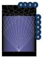
도 11은 α가 55도인 경우에 γ이 43도에서 48도까지 달라짐에 따른 빛의 진행 경로를 나타낸다.11 shows the path of light propagation as γ varies from 43 degrees to 48 degrees when α is 55 degrees.
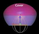
도 12는 바디부(50)를 포함한 조명 장치이며, 도 13은 커버부(40)를 나타낸다.FIG. 12 shows a lighting device including a
도 12를 참조하면, 커버부(40)는 광원(10)와 광 가이드부(20) 및 반사부(30)를 감싸 보호하면서, 동시에 광 가이드부(20)를 통하여 방출된 광을 반사, 굴절 등을 통하여 조명장치의 전면 혹은 후면으로 배광하도록 한다.Referring to FIG. 12, the
커버부(40)의 외면은 벌브 형상을 갖고, 커버부(40)의 내면은 유백색 도료가 코팅될 수 있다. 도료에는 커버부(40)를 통과하는 빛이 커버부(40)의 내면에서 확산되도록 하는 확산제를 포함할 수 있다.The outer surface of the
커버부(40)의 재질은 글라스를 사용할 수 있지만, 무게나 외부 충격에 약한 문제점이 있기 때문에 플라스틱, 폴리프로필렌(PP), 폴리에틸렌(PE), 등을 사용하는 것이 바람직하다. 더욱 바람직하게는 내광성, 내열성, 충격강도 특성이 좋은 광 확산용 폴리카보네이트(PC) 등을 사용하는 것이 좋다.Although the material of the
커버부(40)의 내면 거칠기는 커버부(40)의 외면 거칠기보다 크다. 광원(10)에서 발생된 빛이 커버부(40) 내면에 조사되어 외부로 방출될 때, 커버부(40)의 내면에 조사된 빛이 충분히 산란 및 확산되어 외부로 방출시키기 위함이다. 따라서, 발광 특성이 향상된다.The inner surface roughness of the
도 14는 본 발명의 실시예에 의한 조명 장치에 의한 배광 분포를 나타낸다.14 shows light distribution by the lighting apparatus according to the embodiment of the present invention.
도 14를 참조하면, 본 발명의 실시예에 의한 조명 장치는 전면에 고르게 빛이 배광되며, 후면부에도 우수한 배광도를 갖는 것을 알 수 있다.Referring to FIG. 14, it can be seen that the lighting apparatus according to the embodiment of the present invention has light evenly distributed on the front surface and has excellent light distribution on the rear surface.
본 발명은 상술한 실시형태 및 첨부된 도면에 의해 한정되는 것이 아니고, 첨부된 청구범위에 의해 한정하고자 한다. 또한, 본 발명은 청구범위에 기재된 본 발명의 기술적 사상을 벗어나지 않는 범위 내에서 다양한 형태의 치환, 변형 및 변경이 가능하다는 것은 당 기술분야의 통상의 지식을 가진 자에게 자명할 것이다. 이상에서 실시예들에 설명된 특징, 구조, 효과 등은 본 발명의 적어도 하나의 실시예에 포함되며, 반드시 하나의 실시예에만 한정되는 것은 아니다. 나아가, 각 실시예에서 예시된 특징, 구조, 효과 등은 실시예들이 속하는 분야의 통상의 지식을 가지는 자에 의해 다른 실시예들에 대해서도 조합 또는 변형되어 실시 가능하다. 따라서 이러한 조합과 변형에 관계된 내용들은 본 발명의 범위에 포함되는 것으로 해석되어야 할 것이다.It is intended that the invention not be limited by the foregoing embodiments and the accompanying drawings, but rather by the claims appended hereto. In addition, it will be apparent to those skilled in the art that the present invention may be substituted, modified, and changed in various forms without departing from the technical spirit of the present invention described in the claims. Features, structures, effects, and the like described in the above embodiments are included in at least one embodiment of the present invention, and are not necessarily limited to only one embodiment. Furthermore, the features, structures, effects, and the like illustrated in the embodiments may be combined or modified with respect to other embodiments by those skilled in the art to which the embodiments belong. Therefore, it should be understood that the present invention is not limited to these combinations and modifications.
또한, 이상에서 실시예를 중심으로 설명하였으나 이는 단지 예시일 뿐 본 발명을 한정하는 것이 아니며, 본 발명이 속하는 분야의 통상의 지식을 가진 자라면 본 실시예의 본질적인 특성을 벗어나지 않는 범위에서 이상에 예시되지 않은 여러 가지의 변형과 응용이 가능함을 알 수 있을 것이다. 즉, 실시예에 구체적으로 나타난 각 구성 요소는 변형하여 실시할 수 있는 것이다. 그리고 이러한 변형과 응용에 관계된 차이점들은 첨부된 청구 범위에서 규정하는 본 발명의 범위에 포함되는 것으로 해석되어야 할 것이다.While the present invention has been particularly shown and described with reference to exemplary embodiments thereof, it is clearly understood that the same is by way of illustration and example only and is not to be taken by way of illustration, It can be seen that various modifications and applications are possible. That is, each component specifically shown in the embodiment can be modified. It is to be understood that all changes and modifications that come within the meaning and range of equivalency of the claims are therefore intended to be embraced therein.
1 : 기판
10 : 광원
20 : 광 가이드부
30 : 반사부
40 : 커버부
50 : 바디부1: substrate
10: Light source
20: light guide part
30: reflector
40: cover part
50: body part
Claims (10)
Translated fromKorean상기 기판 상에 배치되어 상기 LED 광원을 감싸는 광 가이드부;
상기 기판 상에 배치되어 상기 LED 광원 및 상기 광 가이드부를 둘러싸는 커버부; 및
상기 광 가이드부상에 배치되고 상기 광원으로부터 입사되는 빛의 적어도 일부를 반사하는 반사부를 포함하는,
조명 장치.
An LED light source disposed on the substrate;
A light guide part disposed on the substrate and surrounding the LED light source;
A cover part disposed on the substrate and surrounding the LED light source and the light guide part; And
A reflection part disposed on the light guide part and reflecting at least a portion of the light incident from the light source;
Lighting device.
상기 광 가이드부는 원기둥 형태로 형성되는 조명 장치.
The method of claim 1,
The light guide unit is formed in a cylindrical shape lighting device.
상기 광 가이드부는 투명하고 굴절률이 1.4 이상인 조명 장치.
The method of claim 1,
And the light guide portion is transparent and has a refractive index of 1.4 or greater.
상기 광 가이드부는 아크릴 수지(PMMA)로 이루어진 조명 장치.
The method of claim 1,
The light guide unit is made of an acrylic resin (PMMA) lighting device.
상기 광원은 적어도 하나의 발광 소자를 포함하는 조명 장치.
The method of claim 1,
The light source includes at least one light emitting device.
상기 반사부는,
상기 커버부의 내부에 위치하고 상기 광 가이드부의 상단에 함몰된 형태로 형성되며, 상기 반사부의 하측에 형성된 반사면에 의해 반사되는 빛의 적어도 일부는 상기 광원보다 더 후방으로 방출되는 조명 장치.
The method of claim 1,
The reflector includes:
The lighting apparatus is disposed in the cover portion and recessed in the upper portion of the light guide portion, and at least a part of the light reflected by the reflecting surface formed on the lower side of the reflector is emitted more rearward than the light source.
상기 반사부는 원뿔 형상으로 형성되는 조명 장치.
The method of claim 1,
The reflection unit is formed in a conical shape.
상기 반사면이 유리로 이루어진 조명 장치.
The method according to claim 6,
Illumination device wherein the reflecting surface is made of glass.
상기 반사면이 평평하게 형성되는 조명 장치.
The method according to claim 6,
Illumination device that the reflecting surface is formed flat.
상기 반사부의 반사면과 상측 수평면과 이루는 각이 43도 이상 48도 이하인 조명 장치.
The method according to claim 6,
An illuminating device having an angle between a reflecting surface of the reflecting unit and an upper horizontal plane of 43 degrees or more and 48 degrees or less.
Priority Applications (2)
| Application Number | Priority Date | Filing Date | Title |
|---|---|---|---|
| KR1020110092453AKR20130029202A (en) | 2011-09-14 | 2011-09-14 | Lighting device |
| PCT/KR2012/007351WO2013039339A2 (en) | 2011-09-14 | 2012-09-13 | Lighting device |
Applications Claiming Priority (1)
| Application Number | Priority Date | Filing Date | Title |
|---|---|---|---|
| KR1020110092453AKR20130029202A (en) | 2011-09-14 | 2011-09-14 | Lighting device |
Publications (1)
| Publication Number | Publication Date |
|---|---|
| KR20130029202Atrue KR20130029202A (en) | 2013-03-22 |
Family
ID=47883886
Family Applications (1)
| Application Number | Title | Priority Date | Filing Date |
|---|---|---|---|
| KR1020110092453ACeasedKR20130029202A (en) | 2011-09-14 | 2011-09-14 | Lighting device |
Country Status (2)
| Country | Link |
|---|---|
| KR (1) | KR20130029202A (en) |
| WO (1) | WO2013039339A2 (en) |
Family Cites Families (6)
| Publication number | Priority date | Publication date | Assignee | Title |
|---|---|---|---|---|
| JPH08106009A (en)* | 1994-10-04 | 1996-04-23 | Niles Parts Co Ltd | Light guide for illumination |
| JP2004311162A (en)* | 2003-04-04 | 2004-11-04 | Stanley Electric Co Ltd | Lighting equipment |
| JP5006584B2 (en)* | 2006-06-19 | 2012-08-22 | キヤノン株式会社 | Irradiation apparatus and irradiation system having the same |
| KR20090014749A (en)* | 2007-08-07 | 2009-02-11 | (주)칸델라 | Illumination light irradiation device |
| KR100968846B1 (en)* | 2008-01-24 | 2010-07-26 | 서울반도체 주식회사 | LED lighting device |
| JP5245545B2 (en)* | 2008-05-30 | 2013-07-24 | 東芝ライテック株式会社 | Light source device and lighting apparatus |
- 2011
- 2011-09-14KRKR1020110092453Apatent/KR20130029202A/ennot_activeCeased
- 2012
- 2012-09-13WOPCT/KR2012/007351patent/WO2013039339A2/enactiveApplication Filing
Also Published As
| Publication number | Publication date |
|---|---|
| WO2013039339A2 (en) | 2013-03-21 |
| WO2013039339A3 (en) | 2013-05-10 |
Similar Documents
| Publication | Publication Date | Title |
|---|---|---|
| CN102760823B (en) | Luminaire and comprise the lighting device of this luminaire | |
| US7845808B2 (en) | Illuminating device | |
| CN102105742B (en) | There is the fluorescent tube substitute of machine-direction oriented light emitting diode | |
| JP6442199B2 (en) | Light emitting device package | |
| KR20130078348A (en) | Lighting device | |
| US7794111B2 (en) | White light illuminator and reading lamp using the same | |
| JP2010192439A (en) | Light emitting device and light guide member for the same | |
| CN101881387A (en) | LED fluorescent lamp | |
| JP5351354B2 (en) | Light distribution control lens, light source device using the same, and lighting fixture | |
| CN102788268B (en) | LED Bulb | |
| KR20120014325A (en) | Optical lenses and lighting devices | |
| TW201510433A (en) | Optical lens and lighting element using the same | |
| CN105264288A (en) | Lens and lighting device | |
| CN102679194B (en) | Led lamp | |
| KR20110088130A (en) | LED lens and LED module for double-sided lighting and LED double-sided lighting device using the same | |
| TWI580902B (en) | Light emitting diode light source module | |
| KR101298576B1 (en) | A led lighting lens having a reflection surface and a led lighting device having thereof | |
| KR20130029203A (en) | Light device | |
| US20110031518A1 (en) | Led device | |
| KR102160775B1 (en) | A light emitting device package | |
| CN102444861B (en) | Light-emitting diode (LED) lens and LED lamp with same | |
| TWI553272B (en) | Side view backlight modul | |
| JP6121745B2 (en) | Surface illumination light emitting device | |
| CN202274328U (en) | Light source module and light emitting device with the light source module | |
| KR20130029202A (en) | Lighting device |
Legal Events
| Date | Code | Title | Description |
|---|---|---|---|
| A201 | Request for examination | ||
| PA0109 | Patent application | St.27 status event code:A-0-1-A10-A12-nap-PA0109 | |
| PA0201 | Request for examination | St.27 status event code:A-1-2-D10-D11-exm-PA0201 | |
| E902 | Notification of reason for refusal | ||
| PE0902 | Notice of grounds for rejection | St.27 status event code:A-1-2-D10-D21-exm-PE0902 | |
| AMND | Amendment | ||
| P11-X000 | Amendment of application requested | St.27 status event code:A-2-2-P10-P11-nap-X000 | |
| P13-X000 | Application amended | St.27 status event code:A-2-2-P10-P13-nap-X000 | |
| PG1501 | Laying open of application | St.27 status event code:A-1-1-Q10-Q12-nap-PG1501 | |
| E601 | Decision to refuse application | ||
| PE0601 | Decision on rejection of patent | St.27 status event code:N-2-6-B10-B15-exm-PE0601 | |
| AMND | Amendment | ||
| E13-X000 | Pre-grant limitation requested | St.27 status event code:A-2-3-E10-E13-lim-X000 | |
| P11-X000 | Amendment of application requested | St.27 status event code:A-2-2-P10-P11-nap-X000 | |
| E801 | Decision on dismissal of amendment | ||
| PE0601 | Decision on rejection of patent | St.27 status event code:N-2-6-B10-B15-exm-PE0601 | |
| PE0801 | Dismissal of amendment | St.27 status event code:A-2-2-P10-P12-nap-PE0801 | |
| PN2301 | Change of applicant | St.27 status event code:A-3-3-R10-R13-asn-PN2301 St.27 status event code:A-3-3-R10-R11-asn-PN2301 | |
| P22-X000 | Classification modified | St.27 status event code:A-2-2-P10-P22-nap-X000 | |
| R18-X000 | Changes to party contact information recorded | St.27 status event code:A-3-3-R10-R18-oth-X000 | |
| R18-X000 | Changes to party contact information recorded | St.27 status event code:A-3-3-R10-R18-oth-X000 | |
| R18-X000 | Changes to party contact information recorded | St.27 status event code:A-3-3-R10-R18-oth-X000 | |
| PN2301 | Change of applicant | St.27 status event code:A-3-3-R10-R13-asn-PN2301 St.27 status event code:A-3-3-R10-R11-asn-PN2301 |