KR20130028446A - A wireless power transmission apparatus and method thereof - Google Patents
A wireless power transmission apparatus and method thereofDownload PDFInfo
- Publication number
- KR20130028446A KR20130028446AKR1020110092013AKR20110092013AKR20130028446AKR 20130028446 AKR20130028446 AKR 20130028446AKR 1020110092013 AKR1020110092013 AKR 1020110092013AKR 20110092013 AKR20110092013 AKR 20110092013AKR 20130028446 AKR20130028446 AKR 20130028446A
- Authority
- KR
- South Korea
- Prior art keywords
- wireless power
- relay
- coil unit
- transmission
- relay coil
- Prior art date
- Legal status (The legal status is an assumption and is not a legal conclusion. Google has not performed a legal analysis and makes no representation as to the accuracy of the status listed.)
- Ceased
Links
Images


Classifications
- H—ELECTRICITY
- H02—GENERATION; CONVERSION OR DISTRIBUTION OF ELECTRIC POWER
- H02J—CIRCUIT ARRANGEMENTS OR SYSTEMS FOR SUPPLYING OR DISTRIBUTING ELECTRIC POWER; SYSTEMS FOR STORING ELECTRIC ENERGY
- H02J50/00—Circuit arrangements or systems for wireless supply or distribution of electric power
- H02J50/50—Circuit arrangements or systems for wireless supply or distribution of electric power using additional energy repeaters between transmitting devices and receiving devices
- H02J50/502—Circuit arrangements or systems for wireless supply or distribution of electric power using additional energy repeaters between transmitting devices and receiving devices the energy repeater being integrated together with the emitter or the receiver
- H—ELECTRICITY
- H02—GENERATION; CONVERSION OR DISTRIBUTION OF ELECTRIC POWER
- H02J—CIRCUIT ARRANGEMENTS OR SYSTEMS FOR SUPPLYING OR DISTRIBUTING ELECTRIC POWER; SYSTEMS FOR STORING ELECTRIC ENERGY
- H02J50/00—Circuit arrangements or systems for wireless supply or distribution of electric power
- H02J50/10—Circuit arrangements or systems for wireless supply or distribution of electric power using inductive coupling
- H02J50/12—Circuit arrangements or systems for wireless supply or distribution of electric power using inductive coupling of the resonant type
- H—ELECTRICITY
- H02—GENERATION; CONVERSION OR DISTRIBUTION OF ELECTRIC POWER
- H02J—CIRCUIT ARRANGEMENTS OR SYSTEMS FOR SUPPLYING OR DISTRIBUTING ELECTRIC POWER; SYSTEMS FOR STORING ELECTRIC ENERGY
- H02J50/00—Circuit arrangements or systems for wireless supply or distribution of electric power
- H02J50/50—Circuit arrangements or systems for wireless supply or distribution of electric power using additional energy repeaters between transmitting devices and receiving devices
- H—ELECTRICITY
- H02—GENERATION; CONVERSION OR DISTRIBUTION OF ELECTRIC POWER
- H02J—CIRCUIT ARRANGEMENTS OR SYSTEMS FOR SUPPLYING OR DISTRIBUTING ELECTRIC POWER; SYSTEMS FOR STORING ELECTRIC ENERGY
- H02J50/00—Circuit arrangements or systems for wireless supply or distribution of electric power
- H02J50/90—Circuit arrangements or systems for wireless supply or distribution of electric power involving detection or optimisation of position, e.g. alignment
- H—ELECTRICITY
- H03—ELECTRONIC CIRCUITRY
- H03H—IMPEDANCE NETWORKS, e.g. RESONANT CIRCUITS; RESONATORS
- H03H3/00—Apparatus or processes specially adapted for the manufacture of impedance networks, resonating circuits, resonators
- H03H3/007—Apparatus or processes specially adapted for the manufacture of impedance networks, resonating circuits, resonators for the manufacture of electromechanical resonators or networks
- H03H3/0072—Apparatus or processes specially adapted for the manufacture of impedance networks, resonating circuits, resonators for the manufacture of electromechanical resonators or networks of microelectro-mechanical resonators or networks
- H03H3/0076—Apparatus or processes specially adapted for the manufacture of impedance networks, resonating circuits, resonators for the manufacture of electromechanical resonators or networks of microelectro-mechanical resonators or networks for obtaining desired frequency or temperature coefficients
- H03H3/0077—Apparatus or processes specially adapted for the manufacture of impedance networks, resonating circuits, resonators for the manufacture of electromechanical resonators or networks of microelectro-mechanical resonators or networks for obtaining desired frequency or temperature coefficients by tuning of resonance frequency
- H—ELECTRICITY
- H04—ELECTRIC COMMUNICATION TECHNIQUE
- H04B—TRANSMISSION
- H04B5/00—Near-field transmission systems, e.g. inductive or capacitive transmission systems
- H04B5/20—Near-field transmission systems, e.g. inductive or capacitive transmission systems characterised by the transmission technique; characterised by the transmission medium
- H04B5/24—Inductive coupling
- H—ELECTRICITY
- H04—ELECTRIC COMMUNICATION TECHNIQUE
- H04B—TRANSMISSION
- H04B5/00—Near-field transmission systems, e.g. inductive or capacitive transmission systems
- H04B5/70—Near-field transmission systems, e.g. inductive or capacitive transmission systems specially adapted for specific purposes
- H04B5/79—Near-field transmission systems, e.g. inductive or capacitive transmission systems specially adapted for specific purposes for data transfer in combination with power transfer
Landscapes
- Engineering & Computer Science (AREA)
- Computer Networks & Wireless Communication (AREA)
- Power Engineering (AREA)
- Signal Processing (AREA)
- Manufacturing & Machinery (AREA)
- Charge And Discharge Circuits For Batteries Or The Like (AREA)
Abstract
Translated fromKoreanDescription
Translated fromKorean본 발명은 무선 전력 전송 기술에 관한 것으로서, 특히 자기 공진 현상을 이용하여 에너지를 효율적으로 전송하는 무선 전력 송신 장치 및 그 방법에 관한 것이다.BACKGROUND OF THE
무선으로 전기 에너지를 원하는 기기로 전달하는 무선 전력 전송 기술(wireless power transmission 또는 wireless energy transfer)은 이미 1800년대에 전자기유도 원리를 이용한 전기 모터나 변압기가 사용되기 시작했고, 그 후로는 라디오 파(radio wave)나 레이저(laser)와 같은 전자기파를 방사해서 전기 에너지를 전송하는 방법도 시도되었다. 우리가 흔히 사용하는 전동 칫솔이나 일부 무선 면도기도 실상은 전자기유도 원리로 충전된다. 현재까지 무선 방식에 의한 에너지 전달 방식은 자기 유도, 자기 공진 및 단파장 무선 주파수를 이용한 원거리 송신 기술 등이 있다.Wireless power transmission technology (wireless power transmission or wireless energy transfer), which transfers electric energy to a desired device wirelessly, has already started to use electric motors or transformers using electromagnetic induction principles in the 1800s, and then radio waves A method of transmitting electrical energy by radiating electromagnetic waves such as waves or lasers has also been attempted. Electric toothbrushes and some cordless shavers that we commonly use are actually charged with the principle of electromagnetic induction. To date, energy transmission methods using wireless methods include magnetic induction, magnetic resonance, and long-distance transmission technology using short wavelength radio frequencies.
최근에 이슈가 되고 있는 단거리 무선 전력 전송 기술의 응용 분야를 보면, 건물 내에 무선 전력 송신 장치를 설치하고, 건물 내부에서 사용자가 휴대폰이나 노트북 등과 같은 모바일 기기 내에 무선 전력 수신 장치를 사용하면 별도의 전원 케이블을 연결하지 않아도 계속해서 충전이 수행되는 경우가 대표적이다.In recent years, the application of short-range wireless power transmission technology, which is an issue, is to install a wireless power transmission device in a building and use a separate power supply when a user uses a wireless power receiver in a mobile device such as a mobile phone or a laptop. Typically, charging is performed even without a cable connected.
그런데, 이러한 무선 전력 전송 기술에서, 자기 공진에 의한 무선 전력 전송이 효율적으로 이루어지기 위해서는, 무선 전력 송신 장치와 무선 전력 수신 장치 사이에 임계값 이상의 결합 계수(coupling coefficient)가 존재하여야 한다. 이때, 상기 결합 계수는 송신 장치의 송신 공진 코일부과 수신 장치의 수신 공진 코일부의 크기 및 양 장치 사이의 거리에 의해 결정된다.However, in such a wireless power transmission technology, in order to efficiently perform wireless power transmission by magnetic resonance, a coupling coefficient greater than or equal to a threshold must exist between the wireless power transmitter and the wireless power receiver. In this case, the coupling coefficient is determined by the size of the transmitting resonant coil unit of the transmitting device and the receiving resonant coil unit of the receiving device and the distance between both devices.
통상, 수신 장치의 수신 공진 코일부의 크기는 송신 장치의 송신 공진 코일부의 크기에 비해 훨씬 작기 때문에, 송신 공진 코일부과 수신 공진 코일부 사이의 결합 계수는 상대적으로 작은 값을 갖게 된다. 이에 따라, 송신 장치와 수신 장치 간에 자기 공진에 의한 에너지 전송 효율은 감소하게 된다. 따라서, 무선 전력 송신 장치에서 무선 전력 수신 장치로 에너지를 효율적으로 전송하기 위한 방안이 요구된다.In general, since the size of the receiving resonant coil portion of the receiving device is much smaller than that of the transmitting resonant coil portion of the transmitting device, the coupling coefficient between the transmitting resonant coil portion and the receiving resonant coil portion has a relatively small value. Accordingly, energy transmission efficiency due to magnetic resonance between the transmitting device and the receiving device is reduced. Therefore, a method for efficiently transmitting energy from the wireless power transmitter to the wireless power receiver is required.
본 발명은 자기 공진 현상을 이용하여 에너지를 전송하는 무선 전력 송신 장치 및 그 방법을 제공한다.The present invention provides a wireless power transmission apparatus and method for transmitting energy using a magnetic resonance phenomenon.
또한, 본 발명은 무선 전력 수신 장치의 위치를 기반으로 에너지를 전송하는 무선 전력 송신 장치 및 그 방법을 제공한다.The present invention also provides a wireless power transmitter and method for transmitting energy based on the location of the wireless power receiver.
또한, 본 발명은 복수의 중계 코일부의 캐패시터를 개별적으로 제어하여 에너지를 전송하는 무선 전력 송신 장치 및 그 방법을 제공한다.The present invention also provides a wireless power transmission apparatus and method for transmitting energy by individually controlling the capacitors of the plurality of relay coils.
본 발명은 전력 공급부로부터 전력을 제공받아 자기장을 발생하는 송신 코일부와, 상기 송신 코일부로부터 수신한 전력을 전송하는 송신 공진 코일부 및 상기 송신 공진 코일부 내부에 배치되어 전력을 중계하는 복수의 중계 코일부를 포함하는 송신 패드; 상기 송신 패드 상에 존재하는 수신 장치의 위치를 검출하기 위한 검출부; 및 상기 검출된 수신 장치의 위치에 대응하는 적어도 하나의 중계 코일부를 결정하고, 상기 적어도 하나의 중계 코일부를 통해 에너지를 전송하도록 제어하는 제어부를 포함하는 자기 공진형 무선 전력 송신 장치를 제공한다.The present invention provides a transmission coil unit receiving power from a power supply unit to generate a magnetic field, a transmission resonant coil unit transmitting power received from the transmission coil unit, and a plurality of relays disposed in the transmission resonant coil unit to relay power. A transmission pad including a relay coil unit; A detector for detecting a position of a receiving device existing on the transmission pad; And a control unit which determines at least one relay coil unit corresponding to the detected position of the receiving device, and controls to transmit energy through the at least one relay coil unit. .
또한, 본 발명은 최 외곽을 따라 일정한 모양으로 배치되는 송신 코일부와, 상기 송신 코일부 내측에 인접하여 배치되는 송신 공진 코일부 및 상기 송신 공진 코일부 내부에 규칙적인 형태로 배열되어 전력을 중계하는 복수의 중계 코일부를 포함하는 송신 패드; 상기 송신 패드 상에 존재하는 수신 장치의 위치를 검출하기 위한 검출부; 및 상기 검출된 수신 장치의 위치에 따라, 상기 복수의 중계 코일부의 캐패시터를 개별적으로 조절하는 제어부를 포함하는 자기 공진형 무선 전력 송신 장치를 제공한다.In addition, the present invention is a transmission coil portion disposed in a constant shape along the outermost, the transmission resonant coil portion disposed adjacent to the inside of the transmission coil portion and arranged in a regular form inside the transmission resonant coil portion to relay power A transmission pad including a plurality of relay coil units; A detector for detecting a position of a receiving device existing on the transmission pad; And a control unit which individually adjusts capacitors of the plurality of relay coil units according to the detected position of the receiving device.
또한, 본 발명은 일정한 형태로 배열된 복수의 중계 코일부를 포함하는 송신부 상에 수신 장치가 위치하는 단계; 무선 전력 송신 장치의 내부 전류량 변화를 측정하고, 상기 측정된 결과를 기반으로 상기 송신부 상에 존재하는 수신 장치의 위치를 검출하는 단계; 상기 수신 장치의 위치에 대응하는 적어도 하나의 중계 코일부를 결정하는 단계; 및 상기 결정된 적어도 하나의 중계 코일부를 통해 에너지를 전송하는 단계를 포함하는 무선 전력 전송 방법을 제공한다.In addition, the present invention includes the steps of placing the receiving device on the transmitting unit including a plurality of relay coil unit arranged in a predetermined form; Measuring a change in the amount of internal current of a wireless power transmitter, and detecting a position of a receiver on the transmitter based on the measured result; Determining at least one relay coil part corresponding to the position of the receiving device; And transmitting energy through the determined at least one relay coil unit.
본 발명의 실시 예에 따르면, 무선 전력 송신 장치는 무선 전력 수신 장치의 위치에 대응하는 중계 코일부를 통해 에너지를 전송함으로써, 무선 전력 수신 장치로의 에너지 전송 효율을 향상할 수 있다.According to an embodiment of the present disclosure, the wireless power transmitter may improve energy transmission efficiency to the wireless power receiver by transmitting energy through the relay coil unit corresponding to the position of the wireless power receiver.
또한, 무선 전력 송신 장치는 특정 중계 코일부를 이용하여 무선 전력 수신 장치로의 에너지 전송을 집중함으로써, 에너지 낭비를 감소할 수 있고 인체에 유해한 자기장의 발생을 감소시킬 수 있다.In addition, the wireless power transmitter may reduce energy waste and reduce generation of a magnetic field harmful to a human body by concentrating energy transmission to the wireless power receiver by using a specific relay coil unit.
한편 그 외의 다양한 효과는 후술될 본 발명의 실시 예에 따른 상세한 설명에서 직접적 또는 암시적으로 개시될 것이다.Meanwhile, various other effects will be directly or implicitly disclosed in the detailed description according to the embodiment of the present invention to be described later.
도 1은 본 발명의 일 실시 예에 따른 무선 전력 전송 시스템을 설명하는 도면;
도 2는 본 발명의 일 실시 예에 따른 송신 코일부의 등가 회로도;
도 3은 본 발명의 일 실시 예에 따른 전력 소스와 송신부의 등가 회로도;
도 4는 본 발명의 일 실시 예에 따른 수신 공진 코일부, 수신 코일부, 평활 회로 및 부하의 등가 회로도;
도 5는 본 발명의 일 실시 예에 따른 무선 전력 송신 장치의 구성도;
도 6은 본 발명의 일 실시 예에 따른 복수의 중계 코일부 제어 방법을 도시한 도면;
도 7은 본 발명의 일 실시 예에 따른 검출부의 구성도.1 is a view for explaining a wireless power transmission system according to an embodiment of the present invention;
2 is an equivalent circuit diagram of a transmitting coil unit according to an exemplary embodiment of the present disclosure;
3 is an equivalent circuit diagram of a power source and a transmitter according to an embodiment of the present invention;
4 is an equivalent circuit diagram of a reception resonance coil unit, a reception coil unit, a smoothing circuit, and a load according to an embodiment of the present invention;
5 is a block diagram of a wireless power transmission apparatus according to an embodiment of the present invention;
6 is a view illustrating a plurality of relay coil control method according to an embodiment of the present invention;
7 is a block diagram of a detector according to an embodiment of the present invention.
하기에서 본 발명을 설명함에 있어 관련된 공지 기능 또는 구성에 대한 구체적인 설명이 본 발명의 요지를 불필요하게 흐릴 수 있다고 판단되는 경우에는 그 상세한 설명을 생략할 것이다. 그리고 후술 되는 용어들은 본 발명에서의 기능을 고려하여 정의된 용어들로서 이는 사용자, 운용자의 의도 또는 관례 등에 따라 달라질 수 있다. 그러므로 그 정의는 본 명세서 전반에 걸친 내용을 토대로 내려져야 할 것이다.In the following description of the present invention, a detailed description of known functions and configurations incorporated herein will be omitted when it may make the subject matter of the present invention rather unclear. The following terms are defined in consideration of the functions of the present invention, and may be changed according to the intentions or customs of the user, the operator, and the like. Therefore, the definition should be based on the contents throughout this specification.
본 발명의 실시 예는 무선 전력 수신 장치의 위치에 대응하는 중계 코일부를 통해 에너지를 전송하는 무선 전력 송신 장치 및 그 송신 방법을 제공한다.An embodiment of the present invention provides a wireless power transmitter and a transmission method for transmitting energy through the relay coil unit corresponding to the position of the wireless power receiver.
이하, 본 발명의 실시 예에 대해 첨부된 도면들을 참조하여 설명하도록 한다.Hereinafter, embodiments of the present invention will be described with reference to the accompanying drawings.
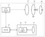
도 1은 본 발명의 일 실시 예에 따른 무선 전력 전송 시스템을 나타낸다.1 illustrates a wireless power transmission system according to an embodiment of the present invention.
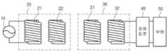
도 1을 참조하면, 무선 전력 전송 시스템은 전력 소스(10), 전력 송신부(20), 전력 수신부(30), 정류 회로(40) 및 부하(50)를 포함한다.Referring to FIG. 1, a wireless power transmission system includes a
전력 소스(10)에서 생성된 전력은 전력 송신부(20)로 전달되고, 자기 공진 현상에 의해 전력 송신부(20)와 공진을 이루는 즉, 공진 주파수 값이 동일한 전력 수신부(30)로 전달된다. 전력 수신부(30)로 전달된 전력은 정류 회로(40)를 거쳐 부하(50)로 전달된다. 이때, 상기 부하(50)는 충전지 또는 기타 전력을 필요로 하는 임의의 장치일 수 있다.The power generated by the
좀 더 구체적으로, 전력 소스(10)는 소정의 주파수를 갖는 교류 전력을 제공하는 교류 전력 소스이다.More specifically, the
전력 송신부(20)는 송신 코일부(21)와 송신 공진 코일부(22)로 구성된다. 송신 코일부(21)는 전력 소스(10)와 연결되며, 교류 전류가 흐르게 된다. 송신 코일부(21)에 교류 전류가 흐르면, 전자기 유도에 의해 물리적으로 이격되어 있는 송신 공진 코일부(22)에도 교류 전류가 유도된다. 송신 공진 코일부(22)로 전달된 전력은 자기 공진에 의해 전력 송신부(20)와 공진 회로를 이루는 전력 수신부(30)로 전달된다.The
자기 공진에 의한 전력 전송은 임피던스가 매칭된 2개의 LC 회로 간에 전력이 전송되는 현상으로써, 전자기 유도에 의한 전력 전송보다 먼 거리까지 높은 효율로 전력을 전달할 수 있다.Power transmission by magnetic resonance is a phenomenon in which power is transmitted between two LC circuits with matching impedances, and thus power can be transmitted with greater efficiency up to a far distance than power transmission by electromagnetic induction.
전력 수신부(30)는 수신 공진 코일부(31)과 수신 코일부(32)로 구성된다. 송신 공진 코일부(22)에 의해 송신된 전력은 수신 공진 코일부(31)에 의해 수신되어 수신 공진 코일부(31)에 교류 전류가 흐르게 된다. 수신 공진 코일부(31)로 전달된 전력은 전자기 유도에 의해 수신 코일부(32)로 전달된다. 수신 코일부(32)로 전달된 전력은 정류 회로(40)를 통해 정류되어 부하(50)로 전달된다.The
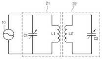
도 2는 본 발명의 일 실시 예에 따른 송신 코일부(21)의 등가 회로이다. 도 2에 도시된 바와 같이, 송신 코일부(21)는 인덕터(L1)와 캐패시터(C1)로 구성될 수 있으며, 이들에 의해 적절한 인덕턴스와 캐패시턴스 값을 갖는 회로를 구성하게 된다.2 is an equivalent circuit of the transmitting
상기 캐패시터(C1)는 고정 캐패시터 또는 가변 캐패시터일 수 있다. 상기 캐패시터(C1)가 가변 캐패시터인 경우, 전력 송신부(20)는 가변 캐패시터를 조절하여 임피던스 매칭을 수행할 수 있다. 한편, 송신 공진 코일부(22), 수신 공진 코일부(31), 수신 코일부(32)의 등가 회로도 도 2에 도시된 것과 동일할 수 있다.The capacitor C1 may be a fixed capacitor or a variable capacitor. When the capacitor C1 is a variable capacitor, the
도 3은 본 발명의 일 실시 예에 따른 전력 소스(10)와 전력 송신부(20)의 등가 회로이다. 도 3에 도시된 바와 같이, 송신 코일부(21)와 송신 공진 코일부(22)는 각각 소정 인덕턴스 값과 캐패시턴스 값을 갖는 인덕터(L1, L2)와 캐패시터(C1, C2)로 구성될 수 있다.3 is an equivalent circuit of the
특히, 송신 공진 코일부(22)의 캐패시터(C2)는 가변 캐패시터일 수 있으며, 전력 송신부(20)는 상기 가변 캐패시터를 조절하여 자기 공진을 위한 공진 주파수 값을 조절할 수 있다.In particular, the capacitor C2 of the transmission
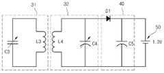
도 4는 본 발명의 일 실시 예에 따른 수신 공진 코일부(31), 수신 코일부(32), 평활 회로(40) 및 부하(50)의 등가 회로이다. 도 4에 도시된 바와 같이, 수신 공진 코일부(31)와 수신 코일부(32)는 각각 소정 인덕턴스 값과 캐패시턴스 값을 갖는 인덕터(L3, L4)와 캐패시터(C3, C4)로 구성될 수 있다.4 is an equivalent circuit of the reception
평활 회로(40)는 다이오드(D1)와 평활 캐패시터(C5)로 구성될 수 있으며, 교류 전력을 직류 전력으로 변환하여 출력한다. 부하(50)는 1.3V의 직류 전원으로 표시되어 있으나, 직류 전력을 필요로 하는 임의의 충전지 또는 장치일 수 있다.The
한편, 이하 본 발명의 실시 예에서는, 상술한 무선 전력 전송 시스템에 무선 전력 중계 기술을 적용한 무선 전력 송신 장치 및 그 방법에 대해 설명하도록 한다.Meanwhile, in the following embodiment of the present invention, a wireless power transmission apparatus and method for applying the wireless power relay technology to the wireless power transmission system described above will be described.
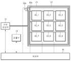
도 5는 본 발명의 일 실시 예에 따른 무선 전력 송신 장치의 구성을 나타낸다.5 shows a configuration of a wireless power transmission apparatus according to an embodiment of the present invention.
도 5를 참조하면, 무선 전력 송신 장치는 전력 공급부(12), 검출부(14), 제어부(16), 송신 코일부(21), 송신 공진 코일부(22) 및 복수의 중계 코일부(60)를 포함한다. 한편, 도 5에서 송신 코일부(21), 송신 공진 코일부(22) 및 복수의 중계 코일부(60)를 제외한 나머지 구성요소들은 도 1의 전력 소스(10)에 포함될 수 있다.Referring to FIG. 5, the wireless power transmitter includes a
무선 전력 송신 장치의 송신 코일부(21), 송신 공진 코일부(22) 및 복수의 중계 코일부(60)는 일체로 형성되어 송신 패드를 구성한다.The
상기 송신 패드는 최 외곽 부분에 사각형 모양으로 감긴 송신 코일부(21)와, 상기 송신 코일부(21) 내부에 동일한 사각형 모양으로 감긴 송신 공진 코일부(22) 및 상기 송신 공진 코일부(22) 내부에 규칙적으로 배열된 복수의 중계 코일부(60)를 포함한다. 한편, 본 실시 예에서, 상기 송신 패드는 사각형 모양으로 형성되는 것을 예시하고 하고 있으나, 이를 제한하지는 않는다.The transmission pad includes a
이러한 송신 패드 위에 무선 전력 수신 장치가 위치하게 되면, 무선 전력 송신 장치는 상기 송신 패드의 송신 공진 코일부 및 중계 코일부를 통해 무선 전력 수신 장치로 에너지를 전송하게 된다.When the wireless power receiver is positioned on the transmission pad, the wireless power transmitter transmits energy to the wireless power receiver through the transmission resonant coil part and the relay coil part of the transmission pad.
전력 공급부(12)는 특정 주파수의 교류 전력을 발생하고, 해당 전력을 송신 패드로 제공한다.The
송신 코일부(21)는 상기 전력 공급부(12)와 연결되며, 그 내부에 교류 전류가 흘러 자기장을 발생한다. 그리고, 상기 송신 코일부(21)는 전자기 유도 현상을 통해 물리적으로 이격되어 있는 송신 공진 코일부(22)로 자기장을 전송한다.The transmitting
송신 공진 코일부(22)가 송신 코일부(21)로부터 자기장을 수신하면, 그 내부에 교류 전류가 유도된다. 그리고, 송신 공진 코일부(22)는 자기 공진 현상을 이용하여 내부에 저장된 에너지를 무선 전력 수신 장치 또는 복수의 중계 코일부(60)로 제공한다. 한편, 자기 공진 현상을 이용한 무선 전력 전송을 위해, 송신 공진 코일부(22)의 공진 주파수와 수신 공진 코일부(미도시) 또는 중계 코일부(60)의 공진 주파수는 서로 일치하여야 한다.When the transmission
송신 공진 코일부(22)는 캐패시터(22a)를 포함하며, 상기 캐패시터(22a)는 고정 캐패시터 또는 가변 캐패시터일 수 있다. 상기 캐패시터(22a)가 가변 캐패시터인 경우, 제어부(16)는 상기 송신 공진 코일부(22)의 캐패시터(22a)를 통해 자기 공진을 위한 공진 주파수 값을 조절할 수 있다.The transmission
가령, 무선 전력 수신 장치는 고정된 인덕턴스 값 및 캐패시턴스 값에 의해 고정된 공진 주파수 값을 갖는다. 이러한 무선 전력 수신 장치로 자기 공진에 의한 에너지 전송을 위해, 무선 전력 송신 장치는 무선 전력 수신 장치의 공진 주파수와 동일한 공진 주파수를 갖도록 송신 공진 코일부(22)의 가변 캐패시터(22a)를 조절하게 된다. 이때, 제어부(16)는 무선 전력 수신 장치의 공진 주파수에 대한 정보를 미리 저장할 수 있다.For example, the wireless power receiver has a fixed inductance value and a fixed resonance frequency value by the capacitance value. In order to transmit energy by magnetic resonance to the wireless power receiver, the wireless power transmitter adjusts the
이러한 무선 전력 송신 장치는 송신 공진 코일부의 공진 주파수 및 무선 전력 수신 장치의 공진 주파수와 동일한 공진 주파수를 갖는 교류 전력을 발생하여 자기 공진에 의한 에너지를 전송하게 된다.The wireless power transmitter generates AC power having the same resonance frequency as that of the transmission resonant coil unit and the resonance frequency of the wireless power receiver to transfer energy due to magnetic resonance.
복수의 중계 코일부(60)는 송신 코일부(21) 및 송신 공진 코일부(22) 내부에 격자 모양 또는 매트릭스 형태로 배열될 수 있다. 즉, 상기 복수의 중계 코일부(60)는 송신 패드의 영역을 복수 개의 균등한 영역들로 구분하도록 형성될 수 있다.The plurality of
또한, 상기 복수의 중계 코일부(60)는 동일한 크기와 모양을 갖도록 구성될 수 있으며, 이를 제한하지는 않는다. 한편, 본 실시 예에서, 상기 복수의 중계 코일부(60)는 총 9개의 중계 코일부(60_1~60_9)가 격자 모양으로 배열되는 것을 예시하고 있으나, 이를 제한하지는 않는다.In addition, the plurality of
복수의 중계 코일부(60)는 송신 공진 코일부(22)로부터 자기 공진을 통해 전송된 에너지를 무선 수신 장치로 중계하는 역할을 수행한다.The plurality of
이때, 상기 복수의 중계 코일부(60)는 무선 전력 수신 장치에 구비된 수신 공진 코일부보다 더 크게 형성하는 것이 바람직하다. 왜냐하면, 효율적인 무선 전력 전송을 위해, 송신 측의 공진 코일과 수신 측의 공진 코일 사이에 임계값 이상의 결합 계수(coupling coefficient)가 존재하여야 하기 때문이다. 따라서, 복수의 중계 코일부(60)를 이용한 에너지 전송 방식은 무선 전력 송신 장치에서 무선 전력 수신 장치로 에너지를 바로 전달하는 방식보다 전송 효율이 증가하게 된다.In this case, the plurality of
또한, 복수의 중계 코일부(60)는 송신 패드 상의 무선 전력 수신 장치의 위치에 따라 특정 중계 코일부만 동작하도록 제어될 수 있다. 이러한 복수의 중계 코일부(60)는 각각 캐패시터(60a)를 포함하며, 상기 캐패시터(60a)는 무선 전력 송신 장치의 제어부(16)와 연결된다. 여기서, 상기 캐패시터(60a)는 고정 캐패시터 또는 가변 캐패시터일 수 있다.In addition, the plurality of
상기 복수의 중계 코일부(60)의 캐패시터가 가변 캐패시터인 경우, 제어부(16)는 무선 전력 수신 장치의 위치에 대응하는 중계 코일부의 가변 캐패시터를 조절하여 송신 공진 코일부 및 수신 공진 코일부의 공진 주파수와 동일한 공진 주파수를 갖도록 한다. 여기서, 상기 무선 전력 수신 장치의 위치에 대응하는 중계 코일부는 해당 무선 전력 수신 장치가 위치하는 송신 패드의 영역 아래에 배치된 중계 코일부를 의미한다.When the capacitors of the plurality of
가령, 도 6의 (a)에 도시된 바와 같이, 상기 제어부(16)는 가변 캐패시터 양단에 전압 값(Vc)을 가변함으로써, 상기 가변 캐패시터의 값을 조절할 수 있다.For example, as shown in FIG. 6A, the
이와 동시에, 상기 제어부(16)는 해당 중계 코일부를 제외한 나머지 중계 코일부, 즉 무선 전력 수신 장치의 위치에 대응하지 않는 중계 코일부의 가변 캐패시터를 조절하여 상기 송신 공진 코일부 및 수신 공진 코일부의 공진 주파수와 다른 공진 주파수를 갖도록 한다.At the same time, the
이러한 제어부(16)의 제어를 통해, 무선 전력 수신 장치의 위치에 대응하는 중계 코일부(60)는 송신 공진 코일부 및 수신 공진 코일부와 자기 공진에 의한 에너지 전송이 이루어지는 반면, 무선 전력 수신 장치의 위치에 대응하지 않는 중계 코일부(60)는 자기 공진에 의한 에너지 전송이 이루어지지 않게 된다.Through the control of the
따라서, 무선 전력 송신 장치는 무선 전력 수신 장치의 위치에 대응하는 중계 코일부(60)를 통해 무선 전력 수신 장치로 에너지 전송을 집중할 수 있게 된다.Therefore, the wireless power transmitter can concentrate energy transmission to the wireless power receiver through the
한편, 상기 복수의 중계 코일부(60)의 캐패시터가 고정 캐패시터인 경우, 상기 제어부(16)는 복수의 중계 코일부(60)의 고정 캐패시터 양단에 병렬로 구성된 스위치를 통해 상기 복수의 중계 코일부(60)를 개별적으로 제어할 수 있다. 이때, 상기 고정 캐패시터는 송신 공진 코일부 및 수신 공진 코일부의 공진 주파수와 동일한 공진 주파수를 갖도록 미리 설정될 수 있다.On the other hand, when the capacitors of the plurality of
가령, 도 6의 (b)에 도시된 바와 같이, 제어부(16)가 무선 전력 수신 장치의 위치에 대응하는 중계 코일부의 고정 캐패시터 양단에 구성된 스위치를 개방(open)하면, 무선 전력 송신 장치는 상기 중계 코일부를 통해 자기 공진에 의한 에너지를 전송할 수 있게 된다.For example, as shown in (b) of FIG. 6, when the
이와 동시에, 상기 제어부(16)가 무선 전력 수신 장치의 위치에 대응하지 않는 중계 코일부의 고정 캐패시터 양단에 구성된 스위치를 단락(short)하면, 무선 전력 송신 장치는 상기 중계 코일부를 통해 자기 공진에 의한 에너지를 전송할 수 없게 된다.At the same time, when the
이러한 제어부(16)의 제어를 통해, 무선 전력 수신 장치의 위치에 대응하는 중계 코일부(60)는 송신 공진 코일부(22) 및 수신 공진 코일부와 자기 공진에 의한 에너지 전송이 이루어지는 반면, 무선 전력 수신 장치의 위치에 대응하지 않는 중계 코일부(60)는 자기 공진에 의한 에너지 전송이 이루어지지 않게 된다.Through the control of the
따라서, 무선 전력 송신 장치는 무선 전력 수신 장치의 위치에 대응하는 중계 코일부(60)를 통해 무선 전력 수신 장치로 에너지 전송을 집중할 수 있게 된다.Therefore, the wireless power transmitter can concentrate energy transmission to the wireless power receiver through the
검출부(14)는 무선 전력 송신 장치의 내부 전류 변화를 검출하고, 상기 전류 변화에 대한 정보를 제어부(16)로 제공한다. 그러면, 상기 제어부(16)는 상기 검출부(14)로부터 제공받은 전류 변화에 대한 정보를 기반으로 무선 전력 수신 장치의 위치를 검출한다.The
이때, 상기 제어부(16)는 복수의 중계 코일부(60)를 순차적으로 하나씩 제어해가면서 무선 전력 수신 장치의 위치를 검출하게 된다. 가령, 상기 제어부(16)는 제1 중계 코일부(60_1) 내지 제9 중계 코일부(60_9)의 가변 캐패시터(60a)를 순차적으로 조절해가면서, 해당 중계 코일부가 위치하는 송신 패드의 영역 위에 무선 전력 수신 장치가 존재하는지 여부를 검출하게 된다.In this case, the
좀 더 구체적으로, 상기 제어부(16)는 송신 공진 코일부 및 수신 공진 코일부의 공진 주파수와 동일한 공진 주파수를 갖도록 제1 중계 코일부(60_1)의 가변 캐패시터를 조절한다. 이때, 상기 제어부(16)는 나머지 중계 코일부들(60_2~60_9)에 대해서는 상기 송신 공진 코일부 및 수신 공진 코일부의 공진 주파수와 다른 공진 주파수를 갖도록 가변 캐패시터를 조절한다.More specifically, the
만약, 상기 제1 중계 코일부(60_1)가 위치하는 송신 패드의 영역 상에 무선 전력 수신 장치가 존재하면, 상기 제1 중계 코일부(60_1)와 상기 무선 전력 수신 장치 사이에 자기 공진 현상에 의한 무선 전력 전송이 발생한다.If a wireless power receiver exists in the area of the transmission pad where the first relay coil unit 60_1 is located, a magnetic resonance phenomenon may occur between the first relay coil unit 60_1 and the wireless power receiver. Wireless power transfer occurs.
상기 무선 전력 전송이 발생하게 되면, 무선 전력 송신 장치의 송신 공진 코일(22) 내에 저장된 에너지의 양이 감소하게 되고, 그에 따라 상기 무선 전력 송신 장치 내부에서 검출되는 전류량도 감소하게 된다. 상기 검출부(14)로부터 이러한 전류량 변화에 대한 정보를 수신하게 되면, 제어부(16)는 상기 제1 중계 코일부(60_1)가 위치하는 송신 패드의 영역 상에 무선 전력 수신 장치가 존재함을 인지하게 된다.When the wireless power transmission occurs, the amount of energy stored in the transmission
이와 달리, 상기 제1 중계 코일부(60_1)가 위치하는 송신 패드의 영역 상에 무선 전력 수신 장치가 존재하지 않으면, 상기 제1 중계 코일부(60_1)와 상기 무선 전력 수신 장치 사이에는 직접적인 무선 전력 전송이 일어나지 않는다.On the contrary, if there is no wireless power receiver on the area of the transmission pad where the first relay coil unit 60_1 is located, direct wireless power is provided between the first relay coil unit 60_1 and the wireless power receiver. No transfer occurs.
이러한 경우, 무선 전력 송신 장치 내부에서 검출되는 전류량의 변화는 크지 않을 것이다. 상기 검출부(14)로부터 이러한 전류량 변화에 대한 정보를 수신하게 되면, 제어부(16)는 상기 제1 중계 코일부(60_1)가 위치하는 송신 패드의 영역 상에 무선 전력 수신 장치가 존재하지 않음을 인지하게 된다.In this case, the change in the amount of current detected inside the wireless power transmitter will not be large. Upon receiving the information on the change in the amount of current from the
상기 제어부(16)는 이러한 과정을 나머지 중계 코일부들에 대해 순차적으로 실시하여 해당 중계 코일부가 위치하는 송신 패드의 영역 상에 무선 전력 수신 장치가 존재하는지 여부를 인지하게 된다. 이때, 상기 제어부(16)는 무선 전력 수신 장치의 위치 검출을 미리 결정된 시간 주기마다 수행할 수 있다.The
무선 전력 수신 장치의 위치에 대한 검출이 완료되면, 상기 제어부(16)는 상기 무선 전력 수신 장치의 위치에 대응하는 중계 코일부를 통해 에너지를 전송하게 된다.When the detection of the position of the wireless power receiver is completed, the
즉, 상기 제어부(16)는 해당 중계 코일부의 공진 주파수가 송신 공진 코일 및 수신 공진 코일의 공진 주파수와 일치하도록 가변 캐패시터를 조절하고, 나머지 중계 코일부의 공진 주파수는 상기 송신 공진 코일 및 수신 공진 코일의 공진 주파수와 다른 값을 갖도록 가변 캐패시터를 조절한다.That is, the
이후, 무선 전력 송신 장치는 무선 전력 수신 장치의 공진 주파수와 동일한 공진 주파수를 갖는 교류 전력을 발생하여, 무선 전력 수신 장치의 위치에 대응하는 중계 코일부를 통해 에너지를 전송하게 된다.Thereafter, the wireless power transmitter generates AC power having the same resonance frequency as that of the wireless power receiver, and transmits energy through the relay coil part corresponding to the position of the wireless power receiver.
이하 실시 예에서는, 무선 전력 수신 장치의 위치를 검출하는 방법에 대해 도면을 참조하여 설명하도록 한다. 한편, 본 실시 예에서, 무선 전력 송신 장치는 전류량 변화를 통해 무선 전력 수신 장치의 위치를 검출하는 방법을 예시하고 있으나, 이를 제한하지는 않는다. 즉, 상기 무선 전력 송신 장치는 전류량 변화를 이용한 검출 방법이 아닌, 송신 패드 상의 압력 센서를 이용한 검출 방법 등을 사용할 수도 있다.In the following embodiment, a method of detecting the position of a wireless power receiver will be described with reference to the drawings. Meanwhile, in the present embodiment, the wireless power transmitter illustrates a method of detecting the position of the wireless power receiver by changing the amount of current, but is not limited thereto. That is, the wireless power transmitter may use a detection method using a pressure sensor on a transmission pad, but not a detection method using a change in current amount.
도 7은 본 발명의 일 실시 예에 따른 검출부의 구성을 나타낸다.7 illustrates a configuration of a detector according to an embodiment of the present invention.
도 7을 참조하면, 검출부(14)는 검출용 코일(11) 및 전류 검출기(13)를 포함한다.Referring to FIG. 7, the
검출용 코일(13)은 송신 공진 코일부(22) 또는 중계 코일부(60)에서 송신되는 자기장의 세기를 검출할 수 있다. 한편, 본 실시 예에서, 상기 검출용 코일(13)은 송신 공진 코일부(22)에서 발생하는 자기장의 세기를 검출하는 것을 예시한다.The detecting
전류 검출기(13)는 상기 검출용 코일(11)에서 검출한 자기장에 의해 발생하는 전력을 전류로 변환하고, 이를 기반으로 전류량 변화를 검출하게 된다. 그리고, 상기 전류 검출기(13)는 상기 전류량 변화에 대한 정보를 제어부(16)로 제공한다.The
이때, 제어부(16)가 상기 전류량 변화를 통해 무선 전력 수신 장치의 위치를 검출하는 원리는 다음과 같다.At this time, the principle that the
도 7에서, 송신 공진 코일부(22) 및 중계 코일부(60)는 공진을 통하여 전력을 저장하는 역할을 한다. 이때, 송신 공진 코일부(22) 및 중계 코일부(60)가 저장하는 에너지의 양은 "입력 전력 x Q(Q = Quality Factor)"이다. 그리고, 송신 공진 코일부(22) 및 중계 코일부(60)의 Q 값은 수신 장치가 송신 장치에 근접하여 수신하는 전력이 많아질수록 낮아진다.In FIG. 7, the transmission
또한, 송신 공진 코일부(22) 및 중계 코일부(60)에서 발생하는 자기력은 내부에 저장된 에너지에 비례하기 때문에, 결과적으로 수신 장치가 송신 장치에 근접할수록 송신 공진 코일부(22) 및 중계 코일부(60)에 저장되는 에너지의 양은 줄어든다. 이에 따라, 상기 송신 공진 코일부(22) 및 중계 코일부(60)에 의해 발생하는 자기장의 세기는 약해지고, 검출용 코일(11)에서 검출되는 전력량도 감소하게 된다.In addition, since the magnetic forces generated by the transmission
즉, 수신 장치가 송신 장치에 근접할수록, 상기 전류 검출기(13)에 검출되는 전류 값은 점점 감소하게 된다. 이러한 전류량 변화를 통해, 제어부(16)는 송신 패드 상에 존재하는 무선 전력 수신 장치의 위치를 검출할 수 있게 된다.That is, as the receiving device approaches the transmitting device, the current value detected by the
한편, 전류 검출기(13)는 무선 전력 수신 장치의 존재 여부를 검출하기 위한 기준 전류 값을 미리 저장할 수 있다. 이때, 상기 기준 전류 값은 송신 패드 상에 무선 전력 수신 장치가 존재하지 않을 때 무선 전력 송신 장치 내부에 흐르는 전류 값을 기초로 설정될 수 있다.Meanwhile, the
상기 전류 검출기(13)는 상기 검출용 코일(11)을 통해 검출한 전류 값과 상기 기준 전류 값을 이용하여 무선 전력 송신 장치의 전류량 변화를 검출하게 된다. 그리고, 상기 전류 검출기(13)는 상기 전류량 변화에 대한 정보를 제어부(16)로 제공한다.The
제어부(16)는 복수의 중계 코일부(60)를 순차적으로 제어해가면서, 상기 검출부(14)에서 제공된 전류량 변화에 대한 정보를 모니터링한다. 그리고, 상기 제어부(16)는 상기 전류량 변화에 대한 정보를 기반으로 송신 패드 상의 어느 영역에 무선 전력 수신 장치가 위치하는지를 검출하게 된다.The
또한, 상기 제어부(16)는 복수의 중계 코일부(60)에 대응하는 복수의 영역들 중 어느 영역에 무선 전력 수신 장치가 위치하는지를 판단하기 위한 임계값을 미리 설정할 필요가 있다. 왜냐하면, 무선 전력 수신 장치가 복수의 영역들 상에 중첩되어 위치하는 경우, 해당 영역에 걸쳐있는 복수의 중계 코일부 모두에서 전류량 변화가 검출되기 때문이다.In addition, the
이러한 임계값 설정을 통해, 상기 제어부(16)는 무선 전력 수신 장치와 가장 많이 중첩되는 영역에 위치하는 중계 코일부를 결정할 수 있게 된다. 따라서, 상기 제어부(16)는 상기 검출부(14)로부터 제공받은 전류량의 변화가 미리 설정된 임계값을 초과하는 경우에만, 해당 중계 코일부 상에 무선 전력 수신 장치가 위치하고 있음을 판단할 수 있다.Through the setting of the threshold value, the
한편, 본 실시 예에서, 상기 전류량 변화를 이용한 수신 장치의 검출이 제어부(16)에 의해 수행되는 것을 예시하고 있으나, 이를 제한하지는 않으며, 검출부(14)에 의해 수행될 수도 있다.Meanwhile, in the present exemplary embodiment, the detection of the receiving device using the change in the amount of current is illustrated by the
무선 전력 수신 장치의 위치에 대한 검출이 완료되면, 상기 제어부(16)는 상기 무선 전력 수신 장치의 위치에 대응하는 중계 코일부를 통해 에너지를 전송할 수 있다.When the detection of the position of the wireless power receiver is completed, the
즉, 상기 제어부(16)는 해당 중계 코일부의 공진 주파수가 송신 공진 코일 및 수신 공진 코일의 공진 주파수와 일치하도록 가변 캐패시터를 조절하고, 나머지 중계 코일부의 공진 주파수는 상기 송신 공진 코일 및 수신 공진 코일의 공진 주파수와 다른 값을 갖도록 가변 캐패시터를 조절한다.That is, the
이후, 무선 전력 송신 장치는 무선 전력 수신 장치의 공진 주파수 값과 동일한 공진 주파수 값을 갖는 교류 전력을 발생하여, 무선 전력 수신 장치의 위치에 대응하는 중계 코일부를 통해 에너지를 전송하게 된다.Thereafter, the wireless power transmitter generates AC power having the same resonance frequency as that of the wireless power receiver, and transmits energy through the relay coil unit corresponding to the position of the wireless power receiver.
상술한 바와 같이, 본 발명의 실시 예에 따른 무선 전력 송신 장치는 송신 패드 상에 존재하는 무선 전력 수신 장치의 위치에 대응하는 중계 코일부를 통해 에너지를 전송함으로써, 상기 무선 전력 수신 장치로의 에너지 전송 효율을 향상할 수 있다.As described above, the wireless power transmitter according to the embodiment of the present invention transmits energy through the relay coil part corresponding to the position of the wireless power receiver present on the transmission pad, thereby transmitting energy to the wireless power receiver. The transmission efficiency can be improved.
한편 이상에서는 본 발명의 구체적인 실시 예에 관해 설명하였으나, 본 발명의 범위에서 벗어나지 않는 한도 내에서 여러 가지 변형이 가능함은 물론이다. 그러므로 본 발명의 범위는 설명된 실시 예에 국한되지 않으며, 후술 되는 특허청구범위뿐만 아니라 이 특허청구범위와 균등한 것들에 의해 정해져야 한다.While the invention has been shown and described with reference to certain preferred embodiments thereof, it will be understood by those skilled in the art that various changes and modifications may be made without departing from the spirit and scope of the invention. Therefore, the scope of the present invention should not be limited to the described embodiments, but should be determined by equivalents to the appended claims, as well as the appended claims.
10 : 전력 소스 20 : 전력 송신부
21 : 송신 코일부 22 : 송신 공진 코일부
30 : 전력 수신부 31 : 수신 공진 코일부
32 : 수신 코일부 40 : 정류회로
50 : 부하 60 : 중계 코일부10: power source 20: power transmitter
21: transmitting coil portion 22: transmitting resonance coil portion
30: power receiving unit 31: receiving resonance coil unit
32: receiving coil portion 40: rectifier circuit
50: load 60: relay coil
Claims (26)
Translated fromKorean전력 공급부로부터 전력을 제공받아 자기장을 발생하는 송신 코일부와, 상기 송신 코일부로부터 수신한 전력을 전송하는 송신 공진 코일부 및 상기 송신 공진 코일부 내부에 배치되어 전력을 중계하는 복수의 중계 코일부를 포함하는 송신부;
상기 송신부 상에 존재하는 수신 장치의 위치를 검출하기 위한 검출부; 및
상기 검출된 수신 장치의 위치에 대응하는 적어도 하나의 중계 코일부를 결정하고, 상기 적어도 하나의 중계 코일부를 통해 에너지를 전송하도록 제어하는 제어부를 포함하는 무선 전력 송신 장치.In the wireless power transmission apparatus using a magnetic resonance,
A transmitting coil unit receiving electric power from a power supply unit to generate a magnetic field, a transmitting resonant coil unit transmitting electric power received from the transmitting coil unit, and a plurality of relay coil units disposed inside the transmitting resonant coil unit to relay power Transmitter comprising a;
A detector for detecting a position of a receiver apparatus existing on the transmitter; And
And a control unit which determines at least one relay coil unit corresponding to the detected position of the receiving device, and controls to transmit energy through the at least one relay coil unit.
최 외곽을 따라 일정한 모양으로 배치되는 송신 코일부와, 상기 송신 코일부 내측에 인접하여 배치되는 송신 공진 코일부 및 상기 송신 공진 코일부 내부에 규칙적인 형태로 배열되어 전력을 중계하는 복수의 중계 코일부를 포함하는 송신부;
상기 송신부 상에 존재하는 수신 장치의 위치를 검출하기 위한 검출부; 및
상기 검출된 수신 장치의 위치에 따라, 상기 복수의 중계 코일부의 캐패시터를 개별적으로 조절하는 제어부를 포함하는 무선 전력 송신 장치.In the wireless power transmission apparatus using a magnetic resonance,
A plurality of relay noses arranged in a regular shape along the outermost portion, a transmission resonant coil portion disposed adjacent to the inside of the transmission coil portion, and a plurality of relay noses arranged in a regular form to relay power; A transmitter including a part;
A detector for detecting a position of a receiver apparatus existing on the transmitter; And
And a control unit for individually adjusting capacitors of the plurality of relay coil units according to the detected position of the receiving device.
상기 송신부 상에 존재하는 수신 장치의 위치를 검출하기 위해 상기 무선 전력 송신 장치의 전류량 변화를 검출하는 무선 전력 송신 장치.3. The apparatus according to claim 1 or 2,
And detecting a change in the amount of current of the wireless power transmitter in order to detect a position of a receiver device present on the transmitter.
상기 송진 공진 코일부에서 발생하는 자기장의 세기를 검출하는 검출용 코일과, 상기 검출용 코일에서 검출한 자기장을 전류로 변환하는 전류 검출기를 포함하는 무선 전력 송신 장치.The method of claim 3, wherein the detection unit,
And a detection coil for detecting the intensity of the magnetic field generated by the rosin resonance coil unit, and a current detector for converting the magnetic field detected by the detection coil into a current.
상기 복수의 중계 코일부를 순차적으로 변경하면서, 상기 검출부를 통해 전류량 변화를 검출하도록 제어하는 무선 전력 송신 장치.The apparatus of claim 3,
And a plurality of relay coil parts sequentially changed to control the current amount change through the detector.
상기 송신부 상의 복수의 영역들 중 어느 영역에 상기 수신 장치가 위치하는지 판단하기 위한 전류량 변화의 임계값을 미리 설정하는 무선 전력 송신 장치.The apparatus of claim 3,
And a preset threshold of a change in the amount of current for determining in which of the plurality of areas on the transmitting unit the receiver is located.
상기 복수의 중계 코일부를 순차적으로 제어하면서, 내부 전류량 변화를 검출하도록 제어하는 무선 전력 송신 장치.The apparatus of claim 3,
And controlling the plurality of relay coil units to detect an internal current amount change while sequentially controlling the plurality of relay coil units.
상기 송신부 상의 압력 센서를 통해 상기 수신 장치의 위치를 검출하는 무선 전력 송신 장치.3. The apparatus according to claim 1 or 2,
Wireless power transmitter for detecting the position of the receiving device through the pressure sensor on the transmitter.
상기 수신 장치의 위치 검출을 미리 결정된 시간 주기마다 반복 수행되도록 제어하는 무선 전력 송신 장치.3. The apparatus according to claim 1 or 2,
And controlling the position detection of the receiving apparatus to be repeated every predetermined time period.
상기 복수의 중계 코일부는 상기 송신부 내에 격자 모양 또는 매트릭스 형태로 배열되는 무선 전력 송신 장치.The method according to claim 1 or 2,
The plurality of relay coil units are wireless power transmitters arranged in a grid or matrix form in the transmitter.
상기 복수의 중계 코일부는 상기 송신부의 영역을 복수 개의 균등한 영역들로 구분하는 무선 전력 송신 장치.The method according to claim 1 or 2,
And the plurality of relay coil parts divide the area of the transmitter into a plurality of equal areas.
상기 복수의 중계 코일부는 상기 수신 장치의 수신 공진 코일부보다 더 크게 형성되는 무선 전력 송신 장치.The method according to claim 1 or 2,
The plurality of relay coils are formed larger than the receiving resonance coil portion of the receiving device.
상기 복수의 중계 코일부의 캐패시터는 가변 캐패시터인 무선 전력 송신 장치.The method of claim 2,
And the capacitors of the plurality of relay coils are variable capacitors.
상기 가변 캐패시터의 조절을 통해 상기 복수의 중계 코일부를 개별적으로 제어하는 무선 전력 송신 장치.The method of claim 13, wherein the control unit,
Wireless power transmission apparatus for individually controlling the plurality of relay coil units by adjusting the variable capacitor.
상기 수신 장치의 위치에 대응하는 중계 코일부의 가변 캐패시터를 조절하여 상기 송신 공진 코일부의 공진 주파수와 동일한 공진 주파수를 갖도록 하는 무선 전력 송신 장치.15. The apparatus of claim 14,
And controlling a variable capacitor of the relay coil unit corresponding to the position of the receiver to have a resonance frequency equal to that of the transmission resonance coil unit.
상기 복수의 중계 코일부의 캐패시터는 고정 캐패시터인 무선 전력 송신 장치.The method of claim 2,
And the capacitors of the plurality of relay coils are fixed capacitors.
상기 고정 캐패시터 양단에 병렬로 연결된 스위치의 개폐를 통해 상기 복수의 중계 코일부를 개별적으로 제어하는 무선 전력 송신 장치.The method of claim 16, wherein the control unit,
And a plurality of relay coil units individually controlled through opening and closing of a switch connected in parallel to both ends of the fixed capacitor.
상기 수신 장치의 위치에 대응하는 중계 코일부의 스위치를 개방하여 상기 송신 공진 코일부의 공진 주파수와 동일한 공진 주파수를 갖도록 하는 무선 전력 송신 장치.18. The apparatus of claim 17,
And opening the switch of the relay coil unit corresponding to the position of the receiver so as to have a resonance frequency equal to that of the transmission resonance coil unit.
일정한 형태로 배열된 복수의 중계 코일부를 포함하는 송신부 상에 수신 장치가 위치하는 단계;
무선 전력 송신 장치의 내부 전류량 변화를 측정하고, 상기 측정된 결과를 기반으로 상기 송신부 상에 존재하는 수신 장치의 위치를 검출하는 단계;
상기 수신 장치의 위치에 대응하는 적어도 하나의 중계 코일부를 결정하는 단계; 및
상기 결정된 적어도 하나의 중계 코일부를 통해 에너지를 전송하는 단계를 포함하는 무선 전력 전송 방법.In the wireless power transmission method using magnetic resonance,
Positioning a receiving device on a transmitting part including a plurality of relay coil parts arranged in a predetermined form;
Measuring a change in the amount of internal current of a wireless power transmitter, and detecting a position of a receiver on the transmitter based on the measured result;
Determining at least one relay coil part corresponding to the position of the receiving device; And
And transmitting energy through the determined at least one relay coil unit.
상기 복수의 중계 코일부를 순차적으로 변경하면서 상기 무선 전력 송신 장치의 전류량 변화를 측정하는 무선 전력 전송 방법.The method of claim 19, wherein the detecting step,
Wireless power transmission method for measuring the change in the amount of current of the wireless power transmitter while sequentially changing the plurality of relay coil units.
상기 송신부 상의 복수의 영역들 중 어느 영역에 상기 수신 장치가 위치하는지 판단하기 위한 전류량 변화의 임계값을 미리 설정하는 단계를 더 포함하는 무선 전력 전송 방법.20. The method of claim 19,
And setting a threshold value of a change in the amount of current for determining which of the plurality of areas on the transmitter is located in the receiving device.
상기 수신 장치의 위치 검출을 미리 결정된 시간 주기마다 반복 수행되도록 제어하는 단계를 더 포함하는 무선 전력 전송 방법.20. The method of claim 19,
And controlling the position detection of the receiving apparatus to be repeatedly performed at a predetermined time period.
상기 복수의 중계 코일부는 상기 송신부 내에 격자 모양 또는 매트릭스 형태로 배열되는 무선 전력 전송 방법.20. The method of claim 19,
The plurality of relay coils are arranged in a grid or matrix form within the transmitter.
상기 복수의 중계 코일부는 상기 송신부의 영역을 복수 개의 균등한 영역들로 구분하는 무선 전력 전송 방법.20. The method of claim 19,
And the plurality of relay coil units divide the area of the transmitter into a plurality of equal areas.
상기 복수의 중계 코일부는 상기 수신 장치의 수신 공진 코일부보다 더 크게 형성되는 무선 전력 전송 방법.20. The method of claim 19,
The plurality of relay coils are formed larger than the receiving resonance coil portion of the receiving device.
상기 수신 장치의 위치에 대응하는 중계 코일부의 가변 캐패시터를 조절하여 송신 공진 코일부의 공진 주파수와 동일한 공진 주파수를 갖도록 설정하는 무선 전력 전송 방법.The method of claim 19, wherein the transmitting step,
And adjusting the variable capacitor of the relay coil part corresponding to the position of the receiver so as to have the same resonance frequency as that of the transmission resonance coil part.
Priority Applications (4)
| Application Number | Priority Date | Filing Date | Title |
|---|---|---|---|
| KR1020110092013AKR20130028446A (en) | 2011-09-09 | 2011-09-09 | A wireless power transmission apparatus and method thereof |
| US14/343,702US9680336B2 (en) | 2011-09-09 | 2012-07-13 | Wireless power repeater and method thereof |
| PCT/KR2012/005590WO2013035978A1 (en) | 2011-09-09 | 2012-07-13 | Wireless power repeater and method thereof |
| US15/589,509US20170244286A1 (en) | 2011-09-09 | 2017-05-08 | Wireless power repeater and method thereof |
Applications Claiming Priority (1)
| Application Number | Priority Date | Filing Date | Title |
|---|---|---|---|
| KR1020110092013AKR20130028446A (en) | 2011-09-09 | 2011-09-09 | A wireless power transmission apparatus and method thereof |
Publications (1)
| Publication Number | Publication Date |
|---|---|
| KR20130028446Atrue KR20130028446A (en) | 2013-03-19 |
Family
ID=47832384
Family Applications (1)
| Application Number | Title | Priority Date | Filing Date |
|---|---|---|---|
| KR1020110092013ACeasedKR20130028446A (en) | 2011-09-09 | 2011-09-09 | A wireless power transmission apparatus and method thereof |
Country Status (3)
| Country | Link |
|---|---|
| US (2) | US9680336B2 (en) |
| KR (1) | KR20130028446A (en) |
| WO (1) | WO2013035978A1 (en) |
Cited By (6)
| Publication number | Priority date | Publication date | Assignee | Title |
|---|---|---|---|---|
| KR20150003553A (en)* | 2013-07-01 | 2015-01-09 | 엘지전자 주식회사 | Wireless power transmitting apparatus |
| KR20150034609A (en)* | 2013-09-26 | 2015-04-03 | 페어차일드코리아반도체 주식회사 | Wireless power transfer system |
| KR20160051501A (en)* | 2014-11-03 | 2016-05-11 | 주식회사 한림포스텍 | Wireless power transmission and charging system |
| CN106304451A (en)* | 2016-09-23 | 2017-01-04 | 中惠创智无线供电技术有限公司 | A kind of wireless power heating system |
| KR20180057006A (en)* | 2016-11-21 | 2018-05-30 | 경희대학교 산학협력단 | Wireless power transmitter for localized power transmission |
| US10523066B2 (en) | 2016-12-21 | 2019-12-31 | Samsung Electronics Co., Ltd. | Wireless power transmission method and apparatus |
Families Citing this family (18)
| Publication number | Priority date | Publication date | Assignee | Title |
|---|---|---|---|---|
| JP6092017B2 (en)* | 2013-06-25 | 2017-03-08 | ルネサスエレクトロニクス株式会社 | Power transmission device, non-contact power feeding system, and control method |
| US10075028B2 (en)* | 2013-12-03 | 2018-09-11 | Utah State University | Determining physical alignment between magnetic couplers for wireless power transfer |
| US20150249343A1 (en) | 2014-03-03 | 2015-09-03 | The Wiremold Company | Wireless power stations |
| EP3157116A4 (en)* | 2014-05-30 | 2018-01-17 | IHI Corporation | Contactless power-supplying system, power-receiving device, and power-transmitting device |
| US10512553B2 (en)* | 2014-07-30 | 2019-12-24 | The Alfred E. Mann Foundation For Scientific Research | Inductive link coil de-tuning compensation and control |
| US11984731B2 (en)* | 2014-12-22 | 2024-05-14 | The Wiremold Company | Ecosystem for surface-based wireless charging system |
| WO2016192075A1 (en)* | 2015-06-04 | 2016-12-08 | Intel Corporation | Coil configuration in a wireless power transmitter |
| WO2017205878A1 (en) | 2016-05-27 | 2017-11-30 | Wireless Advanced Vehicle Electrification, Inc. | Checking alignment of inductive charge pads in motion |
| US11129996B2 (en)* | 2016-06-15 | 2021-09-28 | Boston Scientific Neuromodulation Corporation | External charger for an implantable medical device for determining position and optimizing power transmission using resonant frequency as determined from at least one sense coil |
| KR101846715B1 (en) | 2016-09-26 | 2018-04-10 | 연세대학교 산학협력단 | Apparatus for transmitting wireless power, apparatus for receiving wireless power and system for transmitting wireless power |
| CA3124345A1 (en) | 2017-12-22 | 2019-06-27 | Wireless Advanced Vehicle Electrification, Inc. | Wireless power transfer pad with multiple windings |
| US11462943B2 (en) | 2018-01-30 | 2022-10-04 | Wireless Advanced Vehicle Electrification, Llc | DC link charging of capacitor in a wireless power transfer pad |
| US11437854B2 (en) | 2018-02-12 | 2022-09-06 | Wireless Advanced Vehicle Electrification, Llc | Variable wireless power transfer system |
| CN109004768B (en) | 2018-06-26 | 2022-05-31 | 华为技术有限公司 | Wireless charging device and method |
| CN110932417B (en)* | 2018-08-31 | 2022-03-11 | 北京小米移动软件有限公司 | Wireless power receiving equipment, wireless charging equipment and system |
| US12294228B2 (en)* | 2020-02-28 | 2025-05-06 | University Of Washington | Systems including resonator circuits and methods for wireless charging using same |
| US11228210B2 (en)* | 2020-03-05 | 2022-01-18 | Renesas Electronics America Inc. | Multi-coil wireless power transmitter |
| CN112003389B (en)* | 2020-09-04 | 2021-11-23 | 江苏方天电力技术有限公司 | Robot wireless charging rapid positioning system and method based on multi-transmitting coil array |
Family Cites Families (12)
| Publication number | Priority date | Publication date | Assignee | Title |
|---|---|---|---|---|
| US20060105797A1 (en)* | 2004-11-12 | 2006-05-18 | Motorola, Inc. | Method and apparatus for adjusting a mobile communication device's transmission power |
| US8169185B2 (en) | 2006-01-31 | 2012-05-01 | Mojo Mobility, Inc. | System and method for inductive charging of portable devices |
| US8965461B2 (en) | 2008-05-13 | 2015-02-24 | Qualcomm Incorporated | Reverse link signaling via receive antenna impedance modulation |
| US8878393B2 (en)* | 2008-05-13 | 2014-11-04 | Qualcomm Incorporated | Wireless power transfer for vehicles |
| US9577436B2 (en)* | 2008-09-27 | 2017-02-21 | Witricity Corporation | Wireless energy transfer for implantable devices |
| KR101653759B1 (en) | 2009-05-28 | 2016-09-05 | 주식회사 한림포스텍 | Devices and Methods for Non-contact Power Transmission |
| US8427101B2 (en)* | 2009-11-18 | 2013-04-23 | Nokia Corporation | Wireless energy repeater |
| JP5526795B2 (en)* | 2010-01-15 | 2014-06-18 | ソニー株式会社 | Wireless power supply system |
| JP2011151946A (en) | 2010-01-21 | 2011-08-04 | Sony Corp | Relay coil sheet and wireless power feed system |
| JP5653137B2 (en)* | 2010-08-31 | 2015-01-14 | キヤノン株式会社 | Power supply apparatus and method |
| KR101830649B1 (en)* | 2010-09-10 | 2018-02-23 | 삼성전자주식회사 | Wireless power supply apparatus, wireless charging apparatus and wireless charging system using the same |
| KR101813131B1 (en)* | 2011-05-11 | 2017-12-28 | 삼성전자주식회사 | Wireless power transmission system and method for controlling of resonance frequency and resonance impedance of wireless power transmission system |
- 2011
- 2011-09-09KRKR1020110092013Apatent/KR20130028446A/ennot_activeCeased
- 2012
- 2012-07-13USUS14/343,702patent/US9680336B2/ennot_activeExpired - Fee Related
- 2012-07-13WOPCT/KR2012/005590patent/WO2013035978A1/enactiveApplication Filing
- 2017
- 2017-05-08USUS15/589,509patent/US20170244286A1/ennot_activeAbandoned
Cited By (7)
| Publication number | Priority date | Publication date | Assignee | Title |
|---|---|---|---|---|
| KR20150003553A (en)* | 2013-07-01 | 2015-01-09 | 엘지전자 주식회사 | Wireless power transmitting apparatus |
| KR20150034609A (en)* | 2013-09-26 | 2015-04-03 | 페어차일드코리아반도체 주식회사 | Wireless power transfer system |
| KR20160051501A (en)* | 2014-11-03 | 2016-05-11 | 주식회사 한림포스텍 | Wireless power transmission and charging system |
| KR20210129621A (en)* | 2014-11-03 | 2021-10-28 | 지이 하이브리드 테크놀로지스, 엘엘씨 | Wireless power transmission and charging system |
| CN106304451A (en)* | 2016-09-23 | 2017-01-04 | 中惠创智无线供电技术有限公司 | A kind of wireless power heating system |
| KR20180057006A (en)* | 2016-11-21 | 2018-05-30 | 경희대학교 산학협력단 | Wireless power transmitter for localized power transmission |
| US10523066B2 (en) | 2016-12-21 | 2019-12-31 | Samsung Electronics Co., Ltd. | Wireless power transmission method and apparatus |
Also Published As
| Publication number | Publication date |
|---|---|
| US20170244286A1 (en) | 2017-08-24 |
| US9680336B2 (en) | 2017-06-13 |
| WO2013035978A1 (en) | 2013-03-14 |
| US20140203662A1 (en) | 2014-07-24 |
Similar Documents
| Publication | Publication Date | Title |
|---|---|---|
| KR20130028446A (en) | A wireless power transmission apparatus and method thereof | |
| JP6306816B2 (en) | Wireless power transmission apparatus and power transfer method thereof | |
| EP2761723B1 (en) | Wireless power transmitter, wirless power repeater and wireless power transmission method | |
| EP2597782B1 (en) | Wireless power transmitter and method of transmitting power thereof | |
| KR101882273B1 (en) | Method and apparatus for wireless power reception and method and apparatus for wireless power transmission | |
| KR101947980B1 (en) | Method and apparatus for wireless power transmission and wireless power reception apparatus | |
| JP2014068529A (en) | Wireless power transmitter and method of controlling power thereof | |
| JP2013188127A (en) | Wireless power transmitter, wireless power receiver, and power receiving method | |
| KR101241712B1 (en) | A wireless power reception apparatus and method thereof | |
| KR20120136214A (en) | A wireless power transmission apparatus and method thereof | |
| EP2761634B1 (en) | Wireless power repeater and wireless power transmitter | |
| KR101305833B1 (en) | A wireless power realy apparatus and transmission system | |
| KR20130070612A (en) | Apparatus for transmitting wireless power, apparatus for receiving wireless power, system for transmitting wireless power and method for transmitting wireless power | |
| KR101305657B1 (en) | A wireless power transmission device and trnasmission method | |
| KR101822213B1 (en) | Apparatus for transmitting wireless power, apparatus for receiving wireless power, system for transmitting wireless power and method for transmitting wireless power | |
| KR101360550B1 (en) | Apparatus for transmitting wireless power, apparatus for receiving wireless power, system for transmitting wireless power and method for transmitting wireless power | |
| KR101875974B1 (en) | A wireless power transmission apparatus and method thereof | |
| KR20130094949A (en) | Apparatus for transmitting wireless power, apparatus for receiving wireless power, system for transmitting wireless power and method for transmitting wireless power | |
| KR101745043B1 (en) | A wireless power transmission apparatus and method thereof | |
| KR101428181B1 (en) | Apparatus for transmitting wireless power, apparatus for supplyinging power and method for power controlling thereof and apparatus for supplying power source and method for power controlling thereof | |
| KR20160148239A (en) | Apparatus for receiving wireless power and system for transmitting wireless power | |
| KR20150053536A (en) | Hybrid type wireles power receiving device, method of controlling wireless power signal in hybrid type wireles power receiving device, and magnetic resonance type wireless power receiving device related to the same |
Legal Events
| Date | Code | Title | Description |
|---|---|---|---|
| A201 | Request for examination | ||
| PA0109 | Patent application | Patent event code:PA01091R01D Comment text:Patent Application Patent event date:20110909 | |
| PA0201 | Request for examination | ||
| E902 | Notification of reason for refusal | ||
| PE0902 | Notice of grounds for rejection | Comment text:Notification of reason for refusal Patent event date:20121121 Patent event code:PE09021S01D | |
| AMND | Amendment | ||
| E601 | Decision to refuse application | ||
| PE0601 | Decision on rejection of patent | Patent event date:20130125 Comment text:Decision to Refuse Application Patent event code:PE06012S01D Patent event date:20121121 Comment text:Notification of reason for refusal Patent event code:PE06011S01I | |
| AMND | Amendment | ||
| PX0901 | Re-examination | Patent event code:PX09011S01I Patent event date:20130125 Comment text:Decision to Refuse Application Patent event code:PX09012R01I Patent event date:20130118 Comment text:Amendment to Specification, etc. | |
| PG1501 | Laying open of application | ||
| PX0601 | Decision of rejection after re-examination | Comment text:Decision to Refuse Application Patent event code:PX06014S01D Patent event date:20130327 Comment text:Amendment to Specification, etc. Patent event code:PX06012R01I Patent event date:20130221 Comment text:Decision to Refuse Application Patent event code:PX06011S01I Patent event date:20130125 Comment text:Amendment to Specification, etc. Patent event code:PX06012R01I Patent event date:20130118 Comment text:Notification of reason for refusal Patent event code:PX06013S01I Patent event date:20121121 |