KR20130010892A - Point source transmission and sound velocity correction using multi-opening ultrasound imaging - Google Patents
Point source transmission and sound velocity correction using multi-opening ultrasound imagingDownload PDFInfo
- Publication number
- KR20130010892A KR20130010892AKR1020127024410AKR20127024410AKR20130010892AKR 20130010892 AKR20130010892 AKR 20130010892AKR 1020127024410 AKR1020127024410 AKR 1020127024410AKR 20127024410 AKR20127024410 AKR 20127024410AKR 20130010892 AKR20130010892 AKR 20130010892A
- Authority
- KR
- South Korea
- Prior art keywords
- receiving element
- receiving
- time
- ultrasound image
- point source
- Prior art date
- Legal status (The legal status is an assumption and is not a legal conclusion. Google has not performed a legal analysis and makes no representation as to the accuracy of the status listed.)
- Granted
Links
Images


Classifications
- A—HUMAN NECESSITIES
- A61—MEDICAL OR VETERINARY SCIENCE; HYGIENE
- A61B—DIAGNOSIS; SURGERY; IDENTIFICATION
- A61B8/00—Diagnosis using ultrasonic, sonic or infrasonic waves
- A61B8/13—Tomography
- A61B8/14—Echo-tomography
- A—HUMAN NECESSITIES
- A61—MEDICAL OR VETERINARY SCIENCE; HYGIENE
- A61B—DIAGNOSIS; SURGERY; IDENTIFICATION
- A61B8/00—Diagnosis using ultrasonic, sonic or infrasonic waves
- A61B8/52—Devices using data or image processing specially adapted for diagnosis using ultrasonic, sonic or infrasonic waves
- A61B8/5215—Devices using data or image processing specially adapted for diagnosis using ultrasonic, sonic or infrasonic waves involving processing of medical diagnostic data
- A61B8/5238—Devices using data or image processing specially adapted for diagnosis using ultrasonic, sonic or infrasonic waves involving processing of medical diagnostic data for combining image data of patient, e.g. merging several images from different acquisition modes into one image
- A61B8/5246—Devices using data or image processing specially adapted for diagnosis using ultrasonic, sonic or infrasonic waves involving processing of medical diagnostic data for combining image data of patient, e.g. merging several images from different acquisition modes into one image combining images from the same or different imaging techniques, e.g. color Doppler and B-mode
- A—HUMAN NECESSITIES
- A61—MEDICAL OR VETERINARY SCIENCE; HYGIENE
- A61B—DIAGNOSIS; SURGERY; IDENTIFICATION
- A61B8/00—Diagnosis using ultrasonic, sonic or infrasonic waves
- A61B8/13—Tomography
- A61B8/14—Echo-tomography
- A61B8/145—Echo-tomography characterised by scanning multiple planes
- A—HUMAN NECESSITIES
- A61—MEDICAL OR VETERINARY SCIENCE; HYGIENE
- A61B—DIAGNOSIS; SURGERY; IDENTIFICATION
- A61B8/00—Diagnosis using ultrasonic, sonic or infrasonic waves
- A61B8/44—Constructional features of the ultrasonic, sonic or infrasonic diagnostic device
- A61B8/4444—Constructional features of the ultrasonic, sonic or infrasonic diagnostic device related to the probe
- A61B8/4455—Features of the external shape of the probe, e.g. ergonomic aspects
- A—HUMAN NECESSITIES
- A61—MEDICAL OR VETERINARY SCIENCE; HYGIENE
- A61B—DIAGNOSIS; SURGERY; IDENTIFICATION
- A61B8/00—Diagnosis using ultrasonic, sonic or infrasonic waves
- A61B8/44—Constructional features of the ultrasonic, sonic or infrasonic diagnostic device
- A61B8/4477—Constructional features of the ultrasonic, sonic or infrasonic diagnostic device using several separate ultrasound transducers or probes
- A—HUMAN NECESSITIES
- A61—MEDICAL OR VETERINARY SCIENCE; HYGIENE
- A61B—DIAGNOSIS; SURGERY; IDENTIFICATION
- A61B8/00—Diagnosis using ultrasonic, sonic or infrasonic waves
- A61B8/44—Constructional features of the ultrasonic, sonic or infrasonic diagnostic device
- A61B8/4483—Constructional features of the ultrasonic, sonic or infrasonic diagnostic device characterised by features of the ultrasound transducer
- A—HUMAN NECESSITIES
- A61—MEDICAL OR VETERINARY SCIENCE; HYGIENE
- A61B—DIAGNOSIS; SURGERY; IDENTIFICATION
- A61B8/00—Diagnosis using ultrasonic, sonic or infrasonic waves
- A61B8/46—Ultrasonic, sonic or infrasonic diagnostic devices with special arrangements for interfacing with the operator or the patient
- A61B8/461—Displaying means of special interest
- A61B8/463—Displaying means of special interest characterised by displaying multiple images or images and diagnostic data on one display
- A—HUMAN NECESSITIES
- A61—MEDICAL OR VETERINARY SCIENCE; HYGIENE
- A61B—DIAGNOSIS; SURGERY; IDENTIFICATION
- A61B8/00—Diagnosis using ultrasonic, sonic or infrasonic waves
- A61B8/52—Devices using data or image processing specially adapted for diagnosis using ultrasonic, sonic or infrasonic waves
- A61B8/5207—Devices using data or image processing specially adapted for diagnosis using ultrasonic, sonic or infrasonic waves involving processing of raw data to produce diagnostic data, e.g. for generating an image
- A—HUMAN NECESSITIES
- A61—MEDICAL OR VETERINARY SCIENCE; HYGIENE
- A61B—DIAGNOSIS; SURGERY; IDENTIFICATION
- A61B8/00—Diagnosis using ultrasonic, sonic or infrasonic waves
- A61B8/52—Devices using data or image processing specially adapted for diagnosis using ultrasonic, sonic or infrasonic waves
- A61B8/5269—Devices using data or image processing specially adapted for diagnosis using ultrasonic, sonic or infrasonic waves involving detection or reduction of artifacts
- G—PHYSICS
- G01—MEASURING; TESTING
- G01S—RADIO DIRECTION-FINDING; RADIO NAVIGATION; DETERMINING DISTANCE OR VELOCITY BY USE OF RADIO WAVES; LOCATING OR PRESENCE-DETECTING BY USE OF THE REFLECTION OR RERADIATION OF RADIO WAVES; ANALOGOUS ARRANGEMENTS USING OTHER WAVES
- G01S15/00—Systems using the reflection or reradiation of acoustic waves, e.g. sonar systems
- G01S15/88—Sonar systems specially adapted for specific applications
- G01S15/89—Sonar systems specially adapted for specific applications for mapping or imaging
- G01S15/8906—Short-range imaging systems; Acoustic microscope systems using pulse-echo techniques
- G01S15/8909—Short-range imaging systems; Acoustic microscope systems using pulse-echo techniques using a static transducer configuration
- G01S15/8913—Short-range imaging systems; Acoustic microscope systems using pulse-echo techniques using a static transducer configuration using separate transducers for transmission and reception
- G—PHYSICS
- G01—MEASURING; TESTING
- G01S—RADIO DIRECTION-FINDING; RADIO NAVIGATION; DETERMINING DISTANCE OR VELOCITY BY USE OF RADIO WAVES; LOCATING OR PRESENCE-DETECTING BY USE OF THE REFLECTION OR RERADIATION OF RADIO WAVES; ANALOGOUS ARRANGEMENTS USING OTHER WAVES
- G01S15/00—Systems using the reflection or reradiation of acoustic waves, e.g. sonar systems
- G01S15/88—Sonar systems specially adapted for specific applications
- G01S15/89—Sonar systems specially adapted for specific applications for mapping or imaging
- G01S15/8906—Short-range imaging systems; Acoustic microscope systems using pulse-echo techniques
- G01S15/8909—Short-range imaging systems; Acoustic microscope systems using pulse-echo techniques using a static transducer configuration
- G01S15/8915—Short-range imaging systems; Acoustic microscope systems using pulse-echo techniques using a static transducer configuration using a transducer array
- G01S15/8927—Short-range imaging systems; Acoustic microscope systems using pulse-echo techniques using a static transducer configuration using a transducer array using simultaneously or sequentially two or more subarrays or subapertures
- G—PHYSICS
- G01—MEASURING; TESTING
- G01S—RADIO DIRECTION-FINDING; RADIO NAVIGATION; DETERMINING DISTANCE OR VELOCITY BY USE OF RADIO WAVES; LOCATING OR PRESENCE-DETECTING BY USE OF THE REFLECTION OR RERADIATION OF RADIO WAVES; ANALOGOUS ARRANGEMENTS USING OTHER WAVES
- G01S15/00—Systems using the reflection or reradiation of acoustic waves, e.g. sonar systems
- G01S15/88—Sonar systems specially adapted for specific applications
- G01S15/89—Sonar systems specially adapted for specific applications for mapping or imaging
- G01S15/8906—Short-range imaging systems; Acoustic microscope systems using pulse-echo techniques
- G01S15/8959—Short-range imaging systems; Acoustic microscope systems using pulse-echo techniques using coded signals for correlation purposes
- G01S15/8961—Short-range imaging systems; Acoustic microscope systems using pulse-echo techniques using coded signals for correlation purposes using pulse compression
- G—PHYSICS
- G01—MEASURING; TESTING
- G01S—RADIO DIRECTION-FINDING; RADIO NAVIGATION; DETERMINING DISTANCE OR VELOCITY BY USE OF RADIO WAVES; LOCATING OR PRESENCE-DETECTING BY USE OF THE REFLECTION OR RERADIATION OF RADIO WAVES; ANALOGOUS ARRANGEMENTS USING OTHER WAVES
- G01S15/00—Systems using the reflection or reradiation of acoustic waves, e.g. sonar systems
- G01S15/88—Sonar systems specially adapted for specific applications
- G01S15/89—Sonar systems specially adapted for specific applications for mapping or imaging
- G01S15/8906—Short-range imaging systems; Acoustic microscope systems using pulse-echo techniques
- G01S15/8977—Short-range imaging systems; Acoustic microscope systems using pulse-echo techniques using special techniques for image reconstruction, e.g. FFT, geometrical transformations, spatial deconvolution, time deconvolution
- G—PHYSICS
- G01—MEASURING; TESTING
- G01S—RADIO DIRECTION-FINDING; RADIO NAVIGATION; DETERMINING DISTANCE OR VELOCITY BY USE OF RADIO WAVES; LOCATING OR PRESENCE-DETECTING BY USE OF THE REFLECTION OR RERADIATION OF RADIO WAVES; ANALOGOUS ARRANGEMENTS USING OTHER WAVES
- G01S15/00—Systems using the reflection or reradiation of acoustic waves, e.g. sonar systems
- G01S15/88—Sonar systems specially adapted for specific applications
- G01S15/89—Sonar systems specially adapted for specific applications for mapping or imaging
- G01S15/8906—Short-range imaging systems; Acoustic microscope systems using pulse-echo techniques
- G01S15/8993—Three dimensional imaging systems
- G—PHYSICS
- G01—MEASURING; TESTING
- G01S—RADIO DIRECTION-FINDING; RADIO NAVIGATION; DETERMINING DISTANCE OR VELOCITY BY USE OF RADIO WAVES; LOCATING OR PRESENCE-DETECTING BY USE OF THE REFLECTION OR RERADIATION OF RADIO WAVES; ANALOGOUS ARRANGEMENTS USING OTHER WAVES
- G01S15/00—Systems using the reflection or reradiation of acoustic waves, e.g. sonar systems
- G01S15/88—Sonar systems specially adapted for specific applications
- G01S15/89—Sonar systems specially adapted for specific applications for mapping or imaging
- G01S15/8906—Short-range imaging systems; Acoustic microscope systems using pulse-echo techniques
- G01S15/8997—Short-range imaging systems; Acoustic microscope systems using pulse-echo techniques using synthetic aperture techniques
- G—PHYSICS
- G01—MEASURING; TESTING
- G01S—RADIO DIRECTION-FINDING; RADIO NAVIGATION; DETERMINING DISTANCE OR VELOCITY BY USE OF RADIO WAVES; LOCATING OR PRESENCE-DETECTING BY USE OF THE REFLECTION OR RERADIATION OF RADIO WAVES; ANALOGOUS ARRANGEMENTS USING OTHER WAVES
- G01S7/00—Details of systems according to groups G01S13/00, G01S15/00, G01S17/00
- G01S7/52—Details of systems according to groups G01S13/00, G01S15/00, G01S17/00 of systems according to group G01S15/00
- G01S7/52017—Details of systems according to groups G01S13/00, G01S15/00, G01S17/00 of systems according to group G01S15/00 particularly adapted to short-range imaging
- G01S7/52046—Techniques for image enhancement involving transmitter or receiver
- G01S7/52049—Techniques for image enhancement involving transmitter or receiver using correction of medium-induced phase aberration
Landscapes
- Engineering & Computer Science (AREA)
- Physics & Mathematics (AREA)
- Health & Medical Sciences (AREA)
- Life Sciences & Earth Sciences (AREA)
- Remote Sensing (AREA)
- Radar, Positioning & Navigation (AREA)
- Acoustics & Sound (AREA)
- Surgery (AREA)
- Veterinary Medicine (AREA)
- Heart & Thoracic Surgery (AREA)
- Medical Informatics (AREA)
- Molecular Biology (AREA)
- Radiology & Medical Imaging (AREA)
- Animal Behavior & Ethology (AREA)
- General Health & Medical Sciences (AREA)
- Public Health (AREA)
- Biomedical Technology (AREA)
- Biophysics (AREA)
- Nuclear Medicine, Radiotherapy & Molecular Imaging (AREA)
- Pathology (AREA)
- Computer Networks & Wireless Communication (AREA)
- General Physics & Mathematics (AREA)
- Computer Vision & Pattern Recognition (AREA)
- Gynecology & Obstetrics (AREA)
- Ultra Sonic Daignosis Equipment (AREA)
Abstract
Translated fromKoreanDescription
Translated fromKorean본 출원은 "Alternative Method for Medical Multi-Aperture Ultrasound Imaging"라는 제목으로 2010년 2월 18일자로 출원된 미국 가 특허 출원 번호 제61/305,784호의 우선권을 청구한다.This application claims the priority of US Provisional Patent Application No. 61 / 305,784, filed February 18, 2010 entitled "Alternative Method for Medical Multi-Aperture Ultrasound Imaging."
본 출원은 또한 "Method and Apparatus to Produce Ultrasonic Images Using Multiple Apertures"라는 제목으로 2007년 10월 1일자로 출원된 미국 특허 출원 번호 제11/865,501호 및 "Method and Apparatus to Visualize the Coronary Arteries Using Ultrasound"라는 제목으로 2006년 9월 14일자로 출원된 미국 특허 출원 번호 제11/532,013호와 관련된다.This application also discloses US Patent Application No. 11 / 865,501 and "Method and Apparatus to Visualize the Coronary Arteries Using Ultrasound," filed October 1, 2007, entitled "Method and Apparatus to Produce Ultrasonic Images Using Multiple Apertures." US patent application Ser. No. 11 / 532,013, filed September 14, 2006, entitled.
본 명세서에서 언급된, 특허들 및 특허 출원들을 포함하는 모든 간행물들은 각각의 개별적 간행물이 명확하게 그리고 개별적으로 참조에 의해 통합되는 것으로 표시된 것과 동일한 정도로 그들 전부 참조에 의해 본 명세서에 통합된다.All publications, including patents and patent applications, referred to herein, are hereby incorporated by reference in their entirety to the same extent as if each individual publication was clearly and individually indicated to be incorporated by reference.
종래의 울트라소닉(ultrasonic) 이미징에서, 초음파 에너지의 집속성 빔(focused beam)은 검사될 신체 조직들로 송신되고, 리턴된 에코들이 검출되고 플로팅(plot)되어, 이미지를 형성한다. 종래의 울트라소닉 이미징의 기본 원리들은 Harvey Feigenbaum에 의한 "Echocardiography"의 제1 챕터에 잘 설명된다(Lippincott Williams & Wilkins, 5th ed., Philadelphia, 1993).In conventional ultrasonic imaging, a focused beam of ultrasound energy is transmitted to the body tissues to be inspected, and the returned echoes are detected and plotted to form an image. The basic principles of conventional ultrasonic imaging are well described in the first chapter of "Echocardiography" by Harvey Feigenbaum (Lippincott Williams & Wilkins, 5th ed., Philadelphia, 1993).
신체 조직들에 고주파를 발사하기 위하여, 초음파 빔은 통상적으로 위상 배열(phased array) 또는 성형(shaped) 트랜스듀서 중 하나에 의하여 형성되고 집속된다. 위상 배열 초음파는 의학 초음파 검사에서 이미지들을 형성하기 위하여 좁은 초음파 빔을 스티어링 및 집속시키는 공통적으로 사용된 방법이다. 위상 배열 프로브는 다수의 작은 울트라소닉 트랜스듀서 엘리먼트들을 가지며, 울트라소닉 트랜스듀서 엘리먼트들 각각은 개별적으로 펄싱될 수 있다. 초음파 펄스들의 타이밍을 변화시킴으로써(예를 들어, 행을 따라 차례로 하나씩 엘리먼트들을 펄싱함으로써), 선택된 각도로 지향된 빔을 초래하는 보강 간섭의 패턴이 설정된다. 이것은 빔 스티어링으로서 공지된다. 그러한 스티어링된 초음파 빔은 그 후 검사되는 대상물 또는 조직을 통해 스위프(sweep)될 수 있다. 다수의 빔들로부터의 데이터는 대상물을 통해 슬라이스를 보여주는 시각적 이미지를 만들도록 조합된다.In order to emit high frequency to body tissues, the ultrasound beam is typically formed and focused by either a phased array or shaped transducer. Phased array ultrasound is a commonly used method of steering and focusing a narrow ultrasound beam to form images in medical ultrasound. The phased array probe has a number of small ultrasonic transducer elements, each of which can be individually pulsed. By varying the timing of the ultrasonic pulses (eg, by pulsing elements one by one along the row), a pattern of constructive interference is established that results in a beam directed at a selected angle. This is known as beam steering. Such a steered ultrasound beam can then be swept through the object or tissue to be examined. Data from the multiple beams are combined to create a visual image showing the slice through the object.
전통적으로, 초음파 빔을 송신하기 위하여 사용되는 동일한 트랜스듀서 또는 어레이는 리터닝 에코들을 검출하는데 사용된다. 이 설계 구성은 의학적 목적들로 초음파 이미징의 사용 시 가장 중요한 제한들 중 하나의 핵심에 있다. 이론적으로, 후자의 해결책은 울트라소닉 프로브의 개구의 폭을 증가시킴으로써 향상될 수 있으나, 개구 크기와 함께 수반되는 실제적 문제들은 개구들을 작게 한다. 분명히, 초음파 이미징은 이러한 제한으로도 매우 유용하였지만, 더 우수한 해상도를 이용하는 것이 더욱 효율적일 수 있다.Traditionally, the same transducer or array used to transmit the ultrasonic beam is used to detect the lining echoes. This design configuration is at the heart of one of the most important limitations in the use of ultrasound imaging for medical purposes. In theory, the latter solution can be improved by increasing the width of the opening of the ultrasonic probe, but the practical problems that accompany the opening size make the openings small. Clearly, ultrasound imaging was very useful with these limitations, but using better resolution can be more efficient.
심장학의 업무에서, 예를 들어, 단일 개구 크기에 대한 제한은 늑골들 사이의 공간(늑간격(intercostal space))에 의하여 좌우된다. 그러한 늑간 개구들은 통상적으로 단지 1 내지 2 센티에 불과하도록 제한된다. 복부 및 다른 사용을 위해 의도된 스캐너들에 대해, 개구 크기에 대한 제한은 물리적 제약들에 있어 더 작은 문제이고, 이미지 프로세싱에서의 어려움들에 있어 더 큰 문제이다. 문제는 초음파 송신 속도가 프로브와 관심 영역 사이의 조직의 타입에 따라 변하기 때문에 동상의(in phase) 큰 개구 어레이의 엘리먼트들을 유지하는 것이 어렵다는 것이다. Wells에 의한 책에 따르면(상기 언급됨), 속도는 연성 조직들 내에 +/- 10%까지 변화한다. 개구가 작게 유지될 때(예를 들어, 약 2cm 미만), 추정의 첫번째 순서로, 중간 조직은 모두 동일하며, 어떤 변화도 무시된다. 개구의 크기가 측방 해상도를 향상시키기 위하여 증가될 때, 위상 배열의 부가적인 엘리먼트들은 이상(out of phase)일 수 있으며, 실제로 이미지를 향상시키기보다는 차라리 이미지를 저하시킬 수 있다.In the work of cardiology, for example, the limitation on the size of a single opening depends on the space between the ribs (intercostal space). Such intercostal openings are typically limited to only 1 to 2 centimeters. For scanners intended for abdominal and other uses, the limitation on aperture size is a smaller problem for physical constraints and a larger problem for difficulties in image processing. The problem is that it is difficult to maintain the elements of the large aperture array in phase because the ultrasonic transmission speed varies with the type of tissue between the probe and the region of interest. According to the book by Wells (mentioned above), the rate varies by +/- 10% in soft tissues. When the openings remain small (eg less than about 2 cm), in the first order of estimation, the intermediate tissues are all the same and any change is ignored. When the size of the aperture is increased to improve lateral resolution, additional elements of the phased array may be out of phase and may actually degrade the image rather than enhance it.
Specht에 의한 미국 특허 출원 간행물 2008/0103393호는 더 큰 거리들만큼 분리될 수 있는 다수의 개구들을 이용하는 초음파 이미징 시스템들의 실시예들을 교시하고, 이에 의하여 초음파 이미지들의 측방 해상도에 상당한 향상들을 초래한다.US Patent Application Publication 2008/0103393 by Specht teaches embodiments of ultrasonic imaging systems that use multiple apertures that can be separated by larger distances, thereby resulting in significant improvements in the lateral resolution of ultrasound images.
방법의 일 실시예는, 초음파 이미지를 구성하는 방법을 설명하며, 상기 방법은, 타겟 구역을 통해 제1 어레이 상에서 송신 개구 내에 제1 포인트 소스에 가까운(approximating) 전방향성 비집속성 초음파 파형(omni-directional unfocused ultrasound waveform)을 송신하는 단계, 제2 어레이 상의 제1 수신 개구 상에 배치된 제1 및 제2 수신 엘리먼트들로 타겟 구역으로부터 초음파 에코들을 수신하는 단계 ― 제1 어레이는 제2 어레이로부터 물리적으로 분리됨 ― , 제1 수신 엘리먼트에 대해, 파형이 제1 포인트 소스로부터 제1 타겟 구역의 제1 픽셀 위치로 전파하기 위한 제1 시간을 결정하고, 제2 수신 엘리먼트에 대해, 파형이 제1 포인트 소스로부터 타겟 구역의 제1 픽셀 위치로 전파하기 위한 제2 시간을 결정하는 단계, 및 제1 시간에 제1 수신 엘리먼트에 의하여 수신되는 에코를 제2 시간에 제2 수신 엘리먼트에 의하여 수신되는 에코와 조합함으로써, 제1 픽셀의 제1 초음파 이미지를 형성하는 단계를 포함한다.One embodiment of the method describes a method of constructing an ultrasound image, the method comprising omni-directional omni-directional ultrasound waveforms approaching a first point source within a transmission aperture on a first array via a target region. transmitting a directional unfocused ultrasound waveform, receiving ultrasound echoes from a target region with first and second receiving elements disposed on a first receiving opening on the second array, the first array being physically transmitted from the second array; Separated by-for a first receiving element, determines a first time for the waveform to propagate from the first point source to the first pixel location of the first target region, and for the second receiving element, the waveform is the first point Determining a second time for propagating from a source to a first pixel location in the target region, and received by the first receiving element at the first time Nose by the second receiving and combining echo is received by the element to a second time, and forming a first ultrasound image of the first pixel.
몇몇 실시예들에서, 상기 방법은 타겟 구역의 부가적인 픽셀 위치들에 대해 결정하는 단계 및 형성하는 단계를 반복하는 단계를 더 포함한다. 일 실시예에서, 부가적인 픽셀 위치들은 주사-변환(scan-conversion) 없이 그리드(grid) 상에 위치된다.In some embodiments, the method further includes repeating the determining and forming steps for additional pixel locations of the target region. In one embodiment, additional pixel locations are located on the grid without scan-conversion.
일 실시예에서, 제1 시간 및 제2 시간을 결정하는 단계는 균일한 음속을 추정하는 단계를 포함한다.In one embodiment, determining the first time and the second time includes estimating a uniform sound velocity.
다른 실시예에서, 상기 방법은, 타겟 구역을 통해 송신 개구 내에 제2 포인트 소스에 가까운 제2 전방향성 비집속성 초음파 파형을 송신하는 단계, 제1 수신 개구 상에 배치되는 제1 및 제2 수신 엘리먼트들로 타겟 구역으로부터 초음파 에코들을 수신하는 단계, 제1 수신 엘리먼트에 대해, 제2 파형이 제2 포인트 소스로부터 타겟 구역의 제1 픽셀 위치로 전파하기 위한 제3 시간을 결정하고, 제2 수신 엘리먼트에 대해, 제2 파형이 제2 포인트 소스로부터 타겟 구역의 제1 픽셀 위치로 전파하기 위한 제4 시간을 결정하는 단계, 및 제3 시간에 제1 수신 엘리먼트에 의하여 수신되는 에코를 제4 시간에 제2 수신 엘리먼트에 의하여 수신되는 에코와 조합함으로써, 제1 픽셀의 제2 초음파 이미지를 형성하는 단계를 더 포함한다.In another embodiment, the method includes transmitting a second omnidirectional non-focusing ultrasound waveform close to a second point source within a transmission opening through a target zone, the first and second receiving elements disposed on the first receiving opening. Receiving ultrasonic echoes from the target zone to the first receiving element, determining, for the first receiving element, a third time for the second waveform to propagate from the second point source to the first pixel location of the target zone, and For, determine a fourth time for the second waveform to propagate from the second point source to the first pixel location in the target region, and echo the echo received by the first receiving element at the third time at a fourth time. And in combination with the echo received by the second receiving element, forming a second ultrasound image of the first pixel.
몇몇 실시예들에서, 상기 방법은 제1 초음파 이미지를 제2 초음파 이미지와 조합하는 단계를 더 포함한다. 상기 조합하는 단계는 코히런트 덧셈(coherent addition)을 포함할 수 있다. 다른 실시예에서, 상기 조합하는 단계는 인코히런트 덧셈(incoherent addition)을 포함할 수 있다. 또 다른 실시예에서, 상기 조합하는 단계는 코히런트 덧셈과 인코히런트 덧셈의 조합을 포함할 수 있다.In some embodiments, the method further includes combining the first ultrasound image with the second ultrasound image. The combining step may include coherent addition. In another embodiment, the combining step may include incoherent addition. In another embodiment, the combining may include a combination of coherent and incoherent additions.
몇몇 실시예들에서, 상기 방법은, 제3 어레이상의 제2 수신 개구 상에 배치되는 제3 및 제4 수신 엘리먼트들로 상기 타겟 구역으로부터 초음파 에코들을 수신하는 단계 ― 제3 어레이는 제1 및 제2 어레이들로부터 물리적으로 분리됨 ― , 제3 수신 엘리먼트에 대해, 파형이 제1 포인트 소스로부터 타겟 구역의 제1 픽셀 위치로 전파하기 위한 제3 시간을 결정하고, 제4 수신 엘리먼트에 대해, 파형이 제1 포인트 소스로부터 타겟 구역의 제1 픽셀 위치로 전파하기 위한 제4 시간을 결정하는 단계, 및 제3 시간에 제3 수신 엘리먼트에 의하여 수신되는 에코를 제4 시간에 제4 수신 엘리먼트에 의하여 수신되는 에코와 조합함으로써, 제1 픽셀의 제2 초음파 이미지를 형성하는 단계를 더 포함할 수 있다.In some embodiments, the method further comprises receiving ultrasonic echoes from the target region with third and fourth receiving elements disposed on a second receiving opening on a third array, wherein the third array is the first and the first. Physically separated from the two arrays, determining, for the third receiving element, a third time for the waveform to propagate from the first point source to the first pixel location of the target region, and, for the fourth receiving element, Determining a fourth time for propagating from the first point source to the first pixel location of the target region, and receiving, by the fourth receiving element, an echo received by the third receiving element at a third time at a fourth time In combination with the echoes, the method may further include forming a second ultrasound image of the first pixel.
몇몇 실시예들에서, 상기 방법은 타겟 구역의 부가적인 픽셀 위치들에 대한 결정하는 단계 및 형성하는 단계를 반복하는 단계를 더 포함한다. 몇몇 실시예들에서, 부가적인 픽셀 위치들은 주사-변환 없이 그리드 상에 위치된다.In some embodiments, the method further includes repeating the determining and forming the additional pixel locations of the target region. In some embodiments, additional pixel positions are located on the grid without scan-conversion.
일 실시예에서, 상기 방법은, 타겟 구역을 통해 송신 개구 내에 제2 포인트 소스에 가까운 제2 전방향성 비집속성 초음파 파형을 송신하는 단계, 제1 수신 개구 상에 배치되는 제1 및 제2 수신 엘리먼트들로 그리고 제2 수신 개구 상에 배치되는 제3 및 제4 수신 엘리먼트들로 타겟 구역으로부터 초음파 에코들을 수신하는 단계, 제1 수신 엘리먼트에 대해, 제2 파형이 제2 포인트 소스로부터 타겟 구역의 제1 픽셀 위치로 전파하기 위한 제5 시간을 결정하고, 제2 수신 엘리먼트에 대해, 제2 파형이 제2 포인트 소스로부터 타겟 구역의 제1 픽셀 위치로 전파하기 위한 제6 시간을 결정하고, 제3 수신 엘리먼트에 대해, 제2 파형이 제2 포인트 소스로부터 타겟 구역의 제1 픽셀 위치로 전파하기 위한 제7 시간을 결정하고, 제4 수신 엘리먼트에 대해, 제2 파형이 제2 포인트 소스로부터 타겟 구역의 제1 픽셀 위치로 전파하기 위한 제8 시간을 결정하는 단계, 및 제5 시간에 제1 수신 엘리먼트에 의하여 수신되는 에코를 제6 시간에 제2 수신 엘리먼트에 의하여 수신되는 에코와 조합함으로써 제1 픽셀의 제3 초음파 이미지를 형성하는 단계, 및 제7 시간에 제3 수신 엘리먼트에 의하여 수신되는 에코를 제8 시간에 제4 수신 엘리먼트에 의하여 수신되는 에코와 조합함으로써 제1 픽셀의 제4 초음파 이미지를 형성하는 단계를 더 포함한다.In one embodiment, the method further comprises: transmitting a second omnidirectional non-focusing ultrasound waveform close to the second point source within the transmission opening through the target zone, the first and second receiving elements disposed on the first receiving opening. Receiving ultrasonic echoes from the target zone with third and fourth receiving elements disposed on the second receiving opening, wherein for the first receiving element, the second waveform is generated from the second point source. Determine a fifth time for propagation to one pixel location, and for the second receiving element, determine a sixth time for propagation of the second waveform from the second point source to the first pixel location of the target region, and third For a receiving element, determine a seventh time for the second waveform to propagate from the second point source to the first pixel location of the target region, and for the fourth receiving element, the second waveform is the second wave. Determining an eighth time to propagate from the source to the first pixel location in the target region, and the echo received by the second receiving element at a sixth time to receive the echo received by the first receiving element at a fifth time. Forming a third ultrasound image of the first pixel by combining with and combining the echo received by the third receiving element at a seventh time with the echo received by the fourth receiving element at a eighth time. And forming a fourth ultrasound image of the.
몇몇 실시예들에서, 상기 방법은 제1, 제2, 제3 및 제4 초음파 이미지들을 조합하는 단계를 더 포함한다. 몇몇 실시예들에서, 상기 조합하는 단계는 코히런트 덧셈을 포함한다. 다른 실시예들에서, 상기 조합하는 단계는 인코히런트 덧셈을 포함한다. 부가적인 실시예들에서, 상기 조합하는 단계는 코히런트 덧셈과 인코히런트 덧셈의 조합을 포함한다.In some embodiments, the method further comprises combining the first, second, third and fourth ultrasound images. In some embodiments, the combining step includes coherent addition. In other embodiments, the combining step includes incoherent addition. In additional embodiments, the combining step includes a combination of coherent and incoherent additions.
몇몇 실시예들에서, 상기 방법은 제1 초음파 이미지를 제2 초음파 이미지와 조합하는 단계를 더 포함한다. 상기 조합하는 단계는 코히런트 덧셈을 포함할 수 있다. 다른 실시예에서, 상기 조합하는 단계는 인코히런트 덧셈을 포함할 수 있다. 또 다른 실시예에서, 상기 조합하는 단계는 코히런트 덧셈과 인코히런트 덧셈의 조합을 포함할 수 있다.In some embodiments, the method further includes combining the first ultrasound image with the second ultrasound image. The combining step may include coherent addition. In other embodiments, the combining may include incoherent addition. In another embodiment, the combining may include a combination of coherent and incoherent additions.
몇몇 실시예들에서, 상기 방법은, 제1 초음파 이미지에 관한 제2, 제3 및 제4 초음파 이미지들의 변위(displacement)들을 결정하기 위하여 제1 초음파 이미지를 제2, 제3 및 제4 초음파 이미지들에 비교하는 단계를 더 포함한다.In some embodiments, the method further comprises: first, second, third, and fourth ultrasound images to determine displacements of the second, third, and fourth ultrasound images with respect to the first ultrasound image. The method further comprises the step of comparing to the.
다른 실시예에서, 상기 방법은 제1 초음파 이미지에 관한 제2, 제3 및 제4 초음파 이미지들의 변위들을 보정하는 단계 및 그 후 제1, 제2, 제3 및 제4 초음파 이미지들을 조합하는 단계를 더 포함한다.In another embodiment, the method includes correcting displacements of the second, third and fourth ultrasound images with respect to the first ultrasound image and then combining the first, second, third and fourth ultrasound images. It further includes.
부가적인 실시예에서, 상기 방법은 제1 초음파 이미지에 관한 제2, 제3 및 제4 초음파 이미지들의 변위들을 보정하기 위하여 제3, 제4, 제5, 제6, 제7 및 제8 시간들을 조정하는 단계를 포함한다.In an additional embodiment, the method includes third, fourth, fifth, sixth, seventh and eighth times to correct for displacements of the second, third and fourth ultrasound images with respect to the first ultrasound image. Adjusting.
몇몇 실시예들에서, 상기 방법은 제1 초음파 이미지에 관한 제2 초음파 이미지의 변위를 결정하기 위해 제1 초음파 이미지를 제2 초음파 이미지에 비교하는 단계를 더 포함한다.In some embodiments, the method further includes comparing the first ultrasound image to the second ultrasound image to determine a displacement of the second ultrasound image with respect to the first ultrasound image.
상기 방법은 제1 초음파 이미지에 관한 제2 초음파 이미지의 변위를 보정하는 단계, 및 그 후 제1 및 제2 초음파 이미지들을 조합하는 단계를 더 포함할 수 있다.The method may further comprise correcting the displacement of the second ultrasound image relative to the first ultrasound image, and then combining the first and second ultrasound images.
다른 실시예에서, 상기 방법은 제1 초음파 이미지에 관한 제2 초음파 이미지의 변위를 보정하기 위하여 제3 시간 및 상기 제4 시간을 조정하는 단계를 포함한다.In another embodiment, the method includes adjusting the third time and the fourth time to correct the displacement of the second ultrasound image relative to the first ultrasound image.
몇몇 실시예들에서, 제1 픽셀은 포인트 소스, 제1 수신 엘리먼트, 및 제2 수신 엘리먼트에 의하여 정의되는 평면 외부에 배치된다. 다른 실시예들에서, 제1 픽셀은 포인트 소스, 제1 수신 엘리먼트, 및 제2 수신 엘리먼트에 의하여 정의되는 평면 내에 배치된다.In some embodiments, the first pixel is disposed outside the plane defined by the point source, the first receiving element, and the second receiving element. In other embodiments, the first pixel is disposed in the plane defined by the point source, the first receiving element, and the second receiving element.
다중-개구 초음파 이미징 시스템의 다양한 실시예들이 또한 제공되는데, 상기 다중-개구 초음파 이미징 시스템은, 타겟 구역을 통해 제1 포인트 소스에 가까운 전방향성 비집속성 초음파 파형을 송신하도록 구성되는, 제1 어레이 상의 송신 개구, 제1 및 제2 수신 엘리먼트들을 갖는, 제2 어레이 상의 제1 수신 개구 ― 제2 어레이는 제1 어레이로부터 물리적으로 분리되고, 제1 및 제2 수신 엘리먼트들은 타겟 구역으로부터 초음파 에코들을 수신하도록 구성됨 ― , 송신 개구 및 제1 수신 개구에 커플링되는 제어 시스템 ― 제어 시스템은, 제1 수신 엘리먼트에 대해, 파형이 제1 포인트 소스로부터 타겟 구역의 제1 픽셀 위치로 전파하기 위한 제1 시간을 결정하도록 구성되고, 제2 수신 엘리먼트에 대해, 파형이 제1 포인트 소스로부터 타겟 구역의 제1 픽셀 위치로 전파하기 위한 제2 시간을 결정하도록 구성되며, 제어 시스템은 또한 제1 시간에 제1 수신 엘리먼트에 의하여 수신되는 에코를 제2 시간에 제2 수신 엘리먼트에 의해 수신되는 에코와 조합함으로써 제1 픽셀의 제1 초음파 이미지를 형성하도록 구성됨 ― 을 포함한다.Various embodiments of a multi-aperture ultrasound imaging system are also provided, wherein the multi-aperture ultrasound imaging system is configured to transmit an omnidirectional non-focused ultrasound waveform close to the first point source through a target zone. A first receiving opening on a second array, the transmitting array having first and second receiving elements, the second array being physically separated from the first array, the first and second receiving elements receiving ultrasonic echoes from the target area; A control system coupled to the transmitting opening and the first receiving opening, the control system comprising, for the first receiving element, a first time for the waveform to propagate from the first point source to the first pixel location of the target region; And, for the second receiving element, the waveform is from the first point source above the first pixel of the target region. And determine a second time to propagate to the first pixel, wherein the control system also combines the echo received by the first receiving element at the first time with the echo received by the second receiving element at the second time. And to form a first ultrasound image of the device.
시스템의 몇몇 실시예들에서, 제1 수신 개구와 송신 개구의 물리적 분리부 사이에 배치되는 트랜스듀서 엘리먼트들이 존재하지 않는다.In some embodiments of the system, there are no transducer elements disposed between the physical separation of the first receiving opening and the transmitting opening.
시스템의 일 실시예에서, 송신 개구 및 제1 수신 개구는 송신 개구로부터의 최소 송신 파장의 적어도 2배만큼 분리된다. 다른 실시예에서, 송신 개구 및 수신 개구는 2 cm 내지 10 cm 범위의 전체 개구를 포함한다.In one embodiment of the system, the transmitting opening and the first receiving opening are separated by at least twice the minimum transmission wavelength from the transmitting opening. In another embodiment, the transmitting and receiving openings comprise the entire opening in the range of 2 cm to 10 cm.
몇몇 실시예들에서, 상기 초음파 시스템은 제3 및 제4 수신 엘리먼트들을 갖는, 제3 어레이 상의 제2 수신 개구를 더 포함하며, 제3 어레이는 제1 및 제2 어레이들로부터 물리적으로 분리되고, 제3 및 제4 수신 엘리먼트들은 타겟 구역으로부터 초음파 에코들을 수신하도록 구성된다.In some embodiments, the ultrasound system further includes a second receiving opening on the third array, having third and fourth receiving elements, the third array being physically separated from the first and second arrays, The third and fourth receiving elements are configured to receive ultrasonic echoes from the target zone.
다중-개구 초음파 이미징 시스템의 다른 실시예에서, 제어 시스템은 송신 개구 및 제1 및 제2 수신 개구들에 커플링되고, 제어 시스템은, 제3 수신 엘리먼트에 대해, 파형이 제1 포인트 소스로부터 타겟 구역의 제1 픽셀 위치로 전파하기 위한 제3 시간을 결정하도록 구성되고, 제4 수신 엘리먼트에 대해, 파형이 제1 포인트 소스로부터 타겟 구역의 제1 픽셀 위치로 전파하기 위한 제4 시간을 결정하도록 구성되며, 제어 시스템은 또한 제3 시간에 제3 수신 엘리먼트에 의하여 수신되는 에코를 제4 시간에 제4 수신 엘리먼트에 의하여 수신되는 에코와 조합함으로써 제1 픽셀의 제2 초음파 이미지를 형성하도록 구성된다.In another embodiment of the multi-aperture ultrasound imaging system, the control system is coupled to the transmitting opening and the first and second receiving openings, the control system having a waveform targeted to the third receiving element from the first point source. Determine a third time for propagation to the first pixel location of the zone, and for the fourth receiving element, determine a fourth time for the waveform to propagate from the first point source to the first pixel location of the target zone. And the control system is further configured to form a second ultrasound image of the first pixel by combining the echo received by the third receiving element at the third time with the echo received by the fourth receiving element at the fourth time. .
몇몇 실시예들에서, 제어 시스템은 음속 변화로 인한 제1 초음파 이미지에 관한 제2 초음파 이미지의 변위를 보정하도록 구성된다.In some embodiments, the control system is configured to correct displacement of the second ultrasound image relative to the first ultrasound image due to the change in sound speed.
다중-개구 초음파 이미징 시스템에서, 송신 개구, 제1 수신 개구, 및 제2 수신 개구 모두가 반드시 단일 주사 평면(scan plane)에 있지는 않다.In a multi-aperture ultrasound imaging system, the transmitting opening, the first receiving opening, and the second receiving opening are not necessarily all in a single scan plane.
도 1a는 2-개구 시스템을 도시한다.
도 1b는 송신 트랜스듀서 엘리먼트 및 수신 트랜스듀서 엘리먼트 주변에 타원을 형성하는 등거리 시간 지연 포인트들을 도시한다.
도 1c는 상이한 수신 트랜스듀서 엘리먼트들에 대한 등거리 시간 지연들에 관한 포인트들의 궤적들을 도시한다.
도 2는 3-개구 시스템을 도시한다.
도 3은 디스플레이 및 좌표 시스템을 위한 그리드를 도시한다.
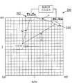
도 4는 3-개구 시스템을 이용한 지방층 모델을 도시한다.
도 5는 포인트 스프레드(spread) 기능의 추정을 위한 구성을 도시한다.1A shows a two-open system.
1B shows equidistant time delay points forming an ellipse around the transmitting transducer element and the receiving transducer element.
1C shows trajectories of points regarding equidistant time delays for different receive transducer elements.
2 shows a three-open system.
3 shows a grid for a display and coordinate system.
4 shows a fat layer model using a three-opening system.
5 shows a configuration for estimating the point spread function.
송신 및 수신 기능들을 위해 다수의 개별 개구들을 사용함으로써 초음파 이미징에서 크게 향상된 측방 해상도가 달성될 수 있다. 본 명세서의 시스템들 및 방법들은 포인트 소스들로부터의 송신 기능들 및 하나 또는 그 초과의 수신 개구들과 송신 개구 사이의 경로를 따라 잠재적으로 다양한 조직 타입들을 통해 이동하는(traveling through) 초음파 펄스들의 음속의 변화들에 대한 보상을 모두 제공할 수 있다. 그러한 음속 보상은 이미지 비교 기법들(예를 들어, 교차-상관) 및 다수의 수신된 이미지 프레임들의 코히런트 및/또는 인코히런트 평균화의 조합에 의하여 수행될 수 있다.Significantly improved lateral resolution in ultrasound imaging can be achieved by using multiple individual apertures for transmit and receive functions. The systems and methods herein describe the transmission functions from point sources and the speed of sound of ultrasonic pulses traveling through potentially various tissue types along a path between one or more receive apertures and a transmit aperture. It can provide all the rewards for the changes in. Such sound speed compensation may be performed by a combination of image comparison techniques (eg, cross-correlation) and coherent and / or incoherent averaging of multiple received image frames.
본 명세서에서 사용되는 바와 같이 용어들 "초음파 트랜스듀서" 및 "트랜스듀서"는 초음파 이미징 기술들의 분야의 당업자들에 의해 이해되는 바와 같은 그들의 통상적 의미들을 지닐 수 있으며, 비제한적으로 전기 신호를 울트라소닉 신호로 및/또는 그 반대로 변환할 수 있는 임의의 단일 컴포넌트를 지칭할 수 있다. 예를 들어, 몇몇 실시예들에서, 초음파 트랜스듀서는 피에조전기 디바이스를 포함할 수 있다. 몇몇 대안적 실시예들에서, 초음파 트랜스듀서들은 용량성 마이크로머시닝된 초음파 트랜스듀서들(CMUT: capacitive micromachined ultrasound transducers)을 포함할 수 있다. 트랜스듀서들은 종종 다수의 엘리먼트들의 어레이들로 구성된다. 트랜스듀서 어레이의 엘리먼트는 어레이의 가장 작은 이산 컴포넌트일 수 있다. 예를 들어, 피에조전기 트랜스듀서 엘리먼트들의 어레이의 경우에, 각각의 엘리먼트는 단일 피에조전기 크리스탈일 수 있다.As used herein, the terms “ultrasonic transducer” and “transducer” may have their usual meanings as understood by those skilled in the art of ultrasonic imaging techniques, and may include but are not limited to ultrasonic electrical signals. It may refer to any single component capable of converting into a signal and / or vice versa. For example, in some embodiments, the ultrasonic transducer may comprise a piezoelectric device. In some alternative embodiments, the ultrasound transducers may include capacitive micromachined ultrasound transducers (CMUT). Transducers often consist of arrays of multiple elements. The elements of the transducer array may be the smallest discrete component of the array. For example, in the case of an array of piezoelectric transducer elements, each element may be a single piezoelectric crystal.
본 명세서에서 사용되는 바와 같이, 용어들 "송신 엘리먼트" 및 "수신 엘리먼트"는 초음파 이미징 기술들의 분야의 당업자에 의하여 이해되는 바와 같은 그들의 통상적 의미들을 지닐 수 있다. 용어 "송신 엘리먼트"는 비제한적으로 전기 신호가 초음파 신호로 변환되는 송신 기능을 적어도 잠깐 동안 수행하는 초음파 트랜스듀서를 지칭할 수 있다. 유사하게, 용어 "수신 엘리먼트"는 비제한적으로 엘리먼트에 영향을 주는 초음파 신호가 전기 신호로 변환되는 수신 기능을 적어도 잠깐 동안 수행하는 초음파 트랜스듀서 엘리먼트를 지칭할 수 있다. 매체로의 초음파의 송신은 또한 "고주파 발사(insonifying)"로서 본 명세서에서 지칭될 수 있다. 초음파 웨이브들을 반사하는 대상물 또는 구조물은 "반사물(reflector)" 또는 "산란체(scatterer)"로서 지칭될 수 있다.As used herein, the terms "transmitting element" and "receiving element" may have their usual meanings as understood by one of ordinary skill in the art of ultrasonic imaging techniques. The term “transmission element” may refer to an ultrasonic transducer that performs at least briefly a transmitting function in which an electrical signal is converted into an ultrasonic signal. Similarly, the term “receive element” may refer to an ultrasonic transducer element that performs at least briefly a receiving function in which an ultrasonic signal affecting the element is converted into an electrical signal. The transmission of the ultrasonic waves to the medium may also be referred to herein as "insonifying". The object or structure that reflects the ultrasonic waves may be referred to as a "reflector" or "scatterer".
본 명세서에서 사용되는 바와 같이 용어 "개구"는 비제한적으로 주어진 순간(instant of time)에 공통 기능을 총괄적으로 수행하는 하나 또는 그 초과의 초음파 트랜스듀서 엘리먼트들을 지칭한다. 예를 들어, 몇몇 실시예들에서, 용어 개구는 송신 기능을 수행하는 트랜스듀서 엘리먼트들의 그룹을 지칭할 수 있다. 대안적인 실시예들에서, 용어 개구는 수신 기능을 수행하는 다수의 트랜스듀서 엘리먼트들을 지칭할 수 있다. 몇몇 실시예들에서, 개구를 형성하는 트랜스듀서 엘리먼트들의 그룹은 상이한 시점들에서 재정립될 수 있다. 도 3은 다수의 개구 초음파 프로브에서 사용되는 다수의 개구들을 보여준다. 프로브의 개구는 3개에 달하는 별개의 피쳐들을 갖는다. 먼저 이것은 종종 다른 개구들에 위치되는 다른 트랜스듀서들로부터 물리적으로 분리된다. 도 3에서, 거리 'd'는 개구(304)로부터 개구(302)를 물리적으로 분리한다. 거리 'd'는 개구(302) 상의 트랜스듀서 엘리먼트들과 개구(304) 상의 트랜스듀서 엘리먼트들 사이의 최소 거리일 수 있다. 몇몇 실시예들에서, 개구들(302 및 304)의 물리적 분리부 사이에 거리 'd'를 따라 트랜스듀서 엘리먼트들이 배치되지 않는다. 몇몇 실시예들에서, 거리 'd'는 송신 개구로부터 송신의 최소 파장의 적어도 2배와 동일할 수 있다. 두번째로, 개구의 트랜스듀서 엘리먼트들은 동일한 직사각형 또는 수평 평면에 있을 필요가 없다. 도 3에서, 개구(304)의 모든 엘리먼트들은 개구(302)의 임의의 엘리먼트로부터의 상이한 수직 위치 'j'를 갖는다. 세번째로, 개구들은 관심 구역에 대한 공통 조준선(line of sight)을 공유하지 않는다. 도 3에서, 개구(302)는 포인트(i, j)에 대한 조준선 'a'를 가지는 한편, 개구(304)는 조준선 'b'를 갖는다. 개구는 임의의 개수의 개별적인 초음파 엘리먼트들을 포함할 수 있다. 개구를 정의하는 초음파 엘리먼트들은 필수적인 것은 아니나, 종종 어레이 내에서 서로에 인접하다. 다중-개구 초음파 이미징 시스템의 동작 동안, 개구의 크기(예를 들어, 초음파 엘리먼트들의 개수 및/또는 크기 및/또는 위치)는 재-할당 엘리먼트들에 의하여 다이나믹하게 변화될 수 있다.As used herein, the term “opening” refers to one or more ultrasonic transducer elements that collectively perform a common function at a given instant of time, without limitation. For example, in some embodiments, the term aperture can refer to a group of transducer elements that perform a transmission function. In alternative embodiments, the term aperture may refer to a number of transducer elements that perform a receiving function. In some embodiments, the group of transducer elements forming the opening can be redefined at different points in time. 3 shows a plurality of apertures used in a plurality of aperture ultrasonic probes. The opening of the probe has up to three distinct features. First it is often physically separated from other transducers located in other openings. In FIG. 3, the distance 'd' physically separates the opening 302 from the
본 명세서에서 사용되는 바와 같이 용어 "포인트 소스 송신"은 단일 공간 위치로부터 매체로 송신된 초음파 에너지의 도입을 지칭할 수 있다. 이것은 단일 초음파 트랜스듀서 엘리먼트 또는 함께 송신하는 인접한 트랜스듀서 엘리먼트들의 조합을 사용하여 달성될 수 있다. 상기 엘리먼트(들)로부터의 단일 송신은 균일한 구형 웨이브프론트에 가깝거나, 또는 2D 슬라이스를 이미징하는 경우에, 이것은 2D 슬라이스 내에 균일한 원형 웨이브프론트를 생성한다. 이 포인트 소스 송신은 트랜스듀서 엘리먼트 어레이로부터 특정 방향으로 에너지를 집속시키는 "위상 배열 송신"으로부터 그것의 공간적 특징들에서 상이하다. 위상 배열 송신은 특정 관심 구역으로 고주파 발사 웨이브(insonifying wave)를 강화시키거나 스티어링하도록, 차례로 트랜스듀서 엘리먼트들의 그룹의 위상을 처리한다. 짧은 지속기간 포인트 소스 송신은 본 명세서에서 "포인트 소스 펄스"로서 지칭된다. 유사하게, 짧은 지속기간 위상 배열 송신은 본 명세서에서 "위상 배열 펄스"로서 지칭된다.As used herein, the term “point source transmission” may refer to the introduction of ultrasonic energy transmitted from a single spatial location to a medium. This can be accomplished using a single ultrasonic transducer element or a combination of adjacent transducer elements transmitting together. A single transmission from the element (s) is close to a uniform spherical wavefront, or if imaging a 2D slice, this creates a uniform circular wavefront within the 2D slice. This point source transmission differs in its spatial characteristics from a "phase array transmission" that focuses energy in a particular direction from the array of transducer elements. Phased array transmissions in turn process the phase of a group of transducer elements to intensify or steer a high frequency injecting wave to a particular region of interest. Short duration point source transmissions are referred to herein as "point source pulses". Similarly, short duration phased array transmission is referred to herein as a "phased array pulse."
본 명세서에서 사용되는 바와 같이, 용어들 "수신 개구", "고주파 발사 개구" 및/또는 "송신 개구"는 초음파 이미징 기술 분야의 당업자들에 의하여 이해되는 바와 같은 그들의 통상적 의미들을 지닐 수 있으며, 원하는 주어진 시간에 개구 또는 원하는 물리적 관점으로부터의 원하는 송신 또는 수신 기능을 수행하는, 개별적인 엘리먼트, 어레이 내의 엘리먼트들의 그룹, 또는 심지어 공통 하우징 내의 전체 어레이들을 지칭할 수 있다. 몇몇 실시예들에서, 이들 다양한 개구들은 전용의 기능을 갖는 물리적 개별 컴포넌트들로서 생성될 수 있다. 대안적 실시예들에서, 상기 기능은 필요에 따라 전자적으로 지정되거나 변화될 수 있다. 다른 추가적 실시예들에서, 개구 기능은 고정형 및 가변형 엘리먼트들 양자의 조합을 수반할 수 있다.As used herein, the terms “receive opening”, “high frequency firing opening” and / or “transmission opening” may have their usual meanings as understood by those skilled in the art of ultrasound imaging, Reference may be made to an individual element, a group of elements within an array, or even an entire array within a common housing that performs a desired transmit or receive function from an opening or a desired physical point of view at a given time. In some embodiments, these various openings may be created as physical discrete components having dedicated functionality. In alternative embodiments, the function may be electronically specified or changed as needed. In other further embodiments, the opening function may involve a combination of both fixed and variable elements.
몇몇 실시예들에서, 개구는 다른 트랜스듀서 어레이들로부터 분리되는 초음파 트랜스듀서들의 어레이이다. 그러한 다수의 개구 초음파 이미징 시스템들은 크게 증가된 측방 해상도를 제공한다. 몇몇 실시예들에 다르면, 다중-개구 이미징 방법은 제1 개구로부터 초음파 펄스로 타겟 대상물에 고주파 발사하는 단계, 제1 개구로부터 소정 거리에 위치 설정되는 제2 개구로 리턴된 에코들을 검출하는 단계, 제1 개구에 관한 제2 개구의 상대적 위치들을 결정하는 단계, 및 타겟 대상물을 통한 음속의 변화들을 보정하면서 이미지들을 조합하기 위하여 리턴된 에코 데이터를 프로세싱하는 단계를 포함한다.In some embodiments, the opening is an array of ultrasonic transducers that are separated from other transducer arrays. Such multiple aperture ultrasound imaging systems provide greatly increased lateral resolution. According to some embodiments, the multi-aperture imaging method includes radio frequency firing from a first opening to a target object with ultrasonic pulses, detecting echoes returned to a second opening positioned at a distance from the first opening, Determining relative positions of the second opening relative to the first opening, and processing the returned echo data to combine the images while correcting changes in the speed of sound through the target object.
몇몇 실시예들에서, 인접한 개구들 사이에 거리 및 배향은 강성 하우징의 사용에 의한 것과 같이, 서로에 관해 고정될 수 있다. 대안적 실시예들에서, 서로에 관한 개구들의 거리들 및 배향들은 이동성 링키지를 이용하는 것과 같이 가변적일 수 있다. 추가적 대안적인 실시예들에서, 개구들은 그룹들이 적어도 명시된 거리만큼 분리되는, 단일의 큰 트랜스듀서 어레이 상에 엘리먼트들의 그룹들로서 정의될 수 있다. 예를 들어, 그러한 시스템의 실시예들은 "Multiple Aperture Medical Ultrasound Transducers "라는 제목으로 2010년 10월 13일자로 출원된 미국 가 특허 출원 번호 제61/392,896호에 도시되고 설명된다. 다중-개구 초음파 이미징 시스템의 몇몇 실시예들에서, 인접한 개구들 사이의 거리는 적어도 하나의 트랜스듀서 엘리먼트의 폭일 수 있다. 대안적 실시예들에서, 개구들 사이의 거리는 특정 애플리케이션 및 프로브 설계의 제약들 내에서 가능한 한 클 수 있다.In some embodiments, the distance and orientation between adjacent openings can be fixed relative to each other, such as by the use of a rigid housing. In alternative embodiments, the distances and orientations of the openings relative to each other can be variable, such as using a movable linkage. In further alternative embodiments, the openings may be defined as groups of elements on a single large transducer array in which the groups are separated at least by a specified distance. For example, embodiments of such a system are shown and described in US Provisional Patent Application No. 61 / 392,896, filed Oct. 13, 2010 entitled “Multiple Aperture Medical Ultrasound Transducers”. In some embodiments of a multi-aperture ultrasound imaging system, the distance between adjacent openings can be the width of at least one transducer element. In alternative embodiments, the distance between the openings may be as large as possible within the constraints of the particular application and probe design.
큰 효과적인 개구(다수의 서브 개구들의 전체 개구)를 갖는 다중-개구 초음파 이미징 시스템은 타겟 조직에서 음속의 변화의 보상에 의해 성공적이 될 수 있다. 이것은 하기에 설명되는 바와 같이, 증가된 개구가 파괴적이기 보다는 효과적일 수 있기 위한 수 개의 방법들 중 하나로 달성될 수 있다.Multi-aperture ultrasound imaging systems with large effective apertures (full apertures of multiple sub-openings) can be successful by compensating for changes in the speed of sound in the target tissue. This can be accomplished in one of several ways, such that the increased opening can be effective rather than disruptive, as described below.
도 1a는 2개의 개구들(개구(102) 및 개구(104))을 포함하는 간략화된 다중-개구 초음파 이미징 시스템(100)의 일 실시예를 예증한다. 개구들(102 및 104) 각각은 다수의 트랜스듀서 엘리먼트들을 포함할 수 있다. 도 1a에 도시된 2-개구 시스템에서, 개구(102)는 전적으로 송신 기능들을 위해 사용될 송신 엘리먼트들(T1 ...Tn)을 포함할 수 있고, 개구(104)는 전적으로 수신 기능들을 위해 사용될 수신 엘리먼트들(R1 ...Rm)을 포함할 수 있다. 대안적 실시예들에서, 송신 엘리먼트들은 수신 엘리먼트들과 배치될 수 있거나, 몇몇 엘리먼트들은 송신 및 수신 기능들 양자 모두를 위해 사용될 수 있다. 도 1a의 다중-개구 초음파 이미징 시스템(100)은 초음파 에너지로 타겟 대상물 또는 내부 조직(T)을 이미징하기 위하여 환자의 피부 표면 상에 위치되도록 구성될 수 있다. 도 1a에 도시된 바와 같이, 개구(102)는 조직(T)으로부터 거리 "a"에 위치설정되고, 개구(104)는 조직(T)로부터 거리 "b"에 위치설정된다. 또한 도 1a에 도시된 바와 같이, MAUI 전자장치는 송신 및 수신 개구들(102 및 104)에 커플링될 수 있다. 몇몇 실시예들에서, MAUI 전자장치는 다중-개구 이미징 시스템(100)을 제어하도록 구성되는 소프트웨어 및 하드웨어를 포함하는, 프로세서, 제어 시스템 또는 컴퓨터 시스템을 포함할 수 있다. 몇몇 실시예들에서, MAUI 전자장치는 개구로부터 전방향성 비집속성 초음파 파형을 송신하기 위하여 시스템을 제어하도록 구성될 수 있다. 하기에서 추가로 상세히 설명될 바와 같이, MAUI 전자장치는 본 명세서에 설명된 방법들 중 임의의 방법을 제어하고 달성하도록 구성될 수 있다.1A illustrates one embodiment of a simplified multi-opening
본 명세서에 설명된 초음파 엘리먼트들 및 어레이들은 또한 다중-기능일 수 있다. 즉, 한 경우에 있어 송신기들로서의 트랜스듀서 엘리먼트들 또는 어레이들의 지정은 다음 경우에서 수신기들로서의 그들의 중간 재-지정을 배제하지 않는다. 또한, 본 명세서에 설명된 제어 시스템의 실시예들은 전자적으로 사용자 입력들 또는 사전-설정 주사 또는 해상도 기준들에 기반하여 그러한 지정들을 하기 위한 능력들을 포함한다.The ultrasonic elements and arrays described herein may also be multi-functional. That is, in one case the designation of transducer elements or arrays as transmitters does not exclude their intermediate re-designation as receivers in the following case. In addition, embodiments of the control system described herein include the capabilities for making such assignments electronically based on user inputs or preset scan or resolution criteria.
다중-개구 초음파 이미징 시스템(200)의 다른 실시예들이 도 2에 도시되며, 개 개구들(202, 204 및 206)을 형성하기 위하여 정렬된 트랜스듀서 엘리먼트들을 포함한다. 일 실시예에서, 개구(202)의 송신 엘리먼트들(T1 ...Tn)은 송신하기 위하여 사용될 수 있고, 개구들(204 및 206)의 수신 엘리먼트들(RR1 ... RRm)은 수신하기 위하여 사용될 수 있다. 대안적 실시예들에서, 모든 개구들의 엘리먼트들은 송신 및 수신 모두를 위해 사용될 수 있다. 도 2의 다중-개구 초음파 이미징 시스템(200)은 초음파 에너지로 조직(T)을 이미징하도록 구성될 수 있다. 또한 도 2에 도시된 바와 같이, MAUI 전자장치는 송신 및 수신 개구들(202 및 204)에 커플링될 수 있다. 몇몇 실시예들에서, MAUI 전자장치는 다중-개구 이미징 시스템(200)을 제어하도록 구성되는 소프트웨어 및 하드웨어를 포함하는, 프로세서, 제어 시스템, 또는 컴퓨팅 시스템을 포함할 수 있다. 몇몇 실시예들에서, MAUI 전자장치는 개구로부터 전방향성 비집속성 초음파 파형을 송신하고, 개구 상에서 에코들을 수신하며, 송신된 파형 및 수신된 에코들로부터 이미지들을 형성하기 위하여 시스템을 제어하도록 구성될 수 있다. 하기에서 추가로 상세히 설명될 바와 같이, MAUI 전자장치는 본 명세서에 설명된 방법들 중 임의의 방법을 제어하고 달성하도록 구성될 수 있다.Other embodiments of the multi-aperture
본 명세서에 설명된 다중-개구 초음파 이미징 시스템들은 임의의 원하는 구성의 트랜스듀서들을 이용하도록 구성될 수 있다. 예를 들어, 1D, 1.5D, 2D, CMUT 또는 임의의 다른 트랜스듀서 어레이들은 전체 해상도 및 시야를 향상시키기 위하여 다중-개구 구성들에서 이용될 수 있다.The multi-aperture ultrasound imaging systems described herein can be configured to use transducers of any desired configuration. For example, 1D, 1.5D, 2D, CMUT or any other transducer arrays can be used in multi-opening configurations to improve overall resolution and field of view.
포인트 소스 송신Send point source
몇몇 실시예들에서, 음향 에너지는 포인트 소스 송신을 사용함으로써 가능한 한 넓은 2-차원 슬라이스로 송신될 수 있다. 예를 들어, 몇몇 실시예들에서, 각각 도 1a 및 2에서의 송신 개구들(102 또는 202)과 같은 송신 개구는 어레이의 단일의 실질적으로 전방향성 트랜스듀서 엘리먼트로부터 포인트 소스 펄스의 형태로 음향 에너지를 송신할 수 있다. 대안적 실시예들에서, 3차원 공간에서 대상물들에 고주파 발사하기 위하여 3 차원에서 상대적으로 넓은 포인트 소스 펄스를 송신하기 위해 다수의 트랜스듀서 엘리먼트들이 공급될(provision) 수 있다. 그러한 실시예들에서, 모든 빔 형성은 수신기들로서 작용하는 트랜스듀서 어레이들과 연관되는 펌웨어 또는 소프트웨어에 의해 달성될 수 있다. 위상 배열 펄스보다는 포인트 소스 펄스로 송신함으로써, 다중-개구 초음파 이미징 기법을 사용하는 것에 대해 다수의 장점들이 존재한다. 예를 들어, 위상 배열 펄스를 사용할 때, 특정 깊이에서 포커스가 맞아야하지만 다른 모든 깊이들에서는 다소 초점이 맞지 않을 것이기 때문에, 송신측 상에서 타이트하게 포커싱하는 것은 문제가 있다. 그에 반해, 포인트 소스 송신으로 전체 2-차원 슬라이스 또는 3-차원 체적은 단일 포인트 소스 송신 펄스로 고주파 발사될 수 있다.In some embodiments, acoustic energy may be transmitted in as wide a two-dimensional slice as possible by using point source transmission. For example, in some embodiments, the transmission openings, such as
도 1a 및 2의 수신 개구들(104 또는 204/206)과 같은, 수신 개구에서 검출되는 각각의 에코는 각각 개별적으로 저장될 수 있다. 수신 개구의 엘리먼트들로 검출되는 에코들이 고주파 발사 또는 송신 개구로부터 매 포인트 소스 펄스에 대해 개별적으로 저장된다면, 전체 2-차원 이미지는 겨우 딱 하나의 엘리먼트에 의하여 수신되는 정보로부터 형성될 수 있다. 이미지의 부가적인 카피들은 고주파 발사 포인트 소스 펄스들의 동일한 세트로부터 데이터를 수집하는 부가적인 수신 개구들에 의하여 형성될 수 있다. 궁극적으로, 다수의 이미지들이 하나 또는 그 초과의 개구들로부터 동시에 생성되고 조합되어 종합적인 2D 또는 3D 이미지를 달성할 수 있다.Each echo detected at the receiving opening, such as receiving
수개의 포인트 소스 펄스들이 통상적으로 고품질 이미지를 생성하기 위하여 사용되나, 각각의 펄스들이 특정 주사 라인 상에서 집속된 경우보다 더 적은 포인트 소스 펄스들이 요구된다. 주어진 시간에 송신될 수 있는 펄스들의 수가 조직에서 초음파의 속도에 의해 엄격하게 제한되기 때문에, 이것은 포인트 소스 펄스를 이용함으로써 두번째마다 더 많은 프레임들이 생성될 수 있다는 실질적인 장점을 산출해낸다. 이것은 움직이는 장기들, 특히 심장을 이미징할 때 매우 중요하다.Several point source pulses are typically used to produce a high quality image, but fewer point source pulses are required than if each pulse was focused on a particular scan line. Since the number of pulses that can be transmitted at a given time is strictly limited by the speed of the ultrasound in the tissue, this yields a substantial advantage that more frames can be generated every second by using a point source pulse. This is very important when imaging moving organs, especially the heart.
몇몇 실시예들에서, 스펙트럼 확산 파형(spread spectrum waveform)은 하나 또는 그 초과의 초음파 트랜스듀서 엘리먼트들로 이루어진 송신 개구 상에 도입될 수 있다. 스펙트럼 확산 파형은 주파수들의 시퀀스, 예컨대, 처프(chirp)(예를 들어, 로우(low)에서 하이(high)로 진행되는 또는 그 반대로 진행되는 주파수들), 랜덤 주파수 시퀀스들(또한 주파수 홉(hop)으로서 지칭됨), 또는 의사 난수 파형에 의하여 생성되는 신호(PN 시퀀스)일 수 있다. 이들 기법들은 총괄적으로 펄스 압축으로서 지칭될 수 있다. 펄스 압축은 깊이 해상도의 손실 없이 더 큰 깊이 침투를 위해 더 긴 펄스들을 제공한다. 사실상, 깊이 해상도는 프로세스에서 크게 향상될 수 있다. 스펙트럼 확산 프로세싱은 통상적으로 지연 및 가중(summation) 단계들 이전에 수신된 신호들 각각의 매칭된 필터링의 형태로 훨신 더 많은 신호 프로세싱을 수반한다. 송신 펄스 형태들의 상기 예들은 단지 예증을 위해 제공된다. 본 명세서에 교지된 기법들은 송신 펄스의 형태와 무관하게 적용될 수 있다.In some embodiments, a spread spectrum waveform can be introduced on the transmission aperture consisting of one or more ultrasonic transducer elements. The spread spectrum waveform is a sequence of frequencies, such as chirp (eg, frequencies running from low to high or vice versa), random frequency sequences (also frequency hops). ), Or a signal (PN sequence) generated by a pseudo random number waveform. These techniques may be referred to collectively as pulse compression. Pulse compression provides longer pulses for greater depth penetration without loss of depth resolution. In fact, the depth resolution can be greatly improved in the process. Spectral spread processing typically involves much more signal processing in the form of matched filtering of each of the signals received prior to delay and summation steps. The above examples of transmit pulse forms are provided for illustration only. The techniques taught herein can be applied regardless of the shape of the transmit pulse.
기본적 이미지 렌더링Basic image rendering
도 1a는 초음파 송신 엘리먼트들(T1, T2, ... Tn)을 갖는 제1 개구(102) 및 초음파 수신 엘리먼트들(R1, R2, ... Rm)을 갖는 제2 개구(104)를 포함하는 다중-개구 초음파 이미징 시스템(100)의 일 실시예를 예증한다. 이 다중-개구 초음파 이미징 시스템(100)은 검사될 대상물 또는 신체(인간 신체와 같은)의 표면 상에 위치되도록 구성된다. 몇몇 실시예들에서, 2개 개구들 모두는 동일한 주사 평면에 대해 민감할 수 있다. 다른 실시예들에서, 개구들 중 하나는 상이한 주사 평면에 있을 수 있다. 각각의 개구의 각각의 트랜스듀서 엘리먼트의 기계적 및 음향적 위치는 공통 기준 포인트에 대해 또는 서로에 대해 정확히 알려져야 한다.FIG. 1A includes a
일 실시예에서, 초음파 이미지는 송신 엘리먼트(예를 들어, 개구(102)의 송신 엘리먼트(T1))로 내부 조직 또는 타겟 대상물(T)(예를 들어, 심장, 장기, 종양, 또는 신체의 다른 부분을 통한 평면)과 같은 이미징될 전체 구역에 고주파 발사하고, 그 후 수신 엘리먼트(예를 들어, 개구(104)의 수신 엘리먼트(R1)) 상에서 전체 이미징된 평면으로부터 에코들을 수신함으로써 생성될 수 있다. 몇몇 실시예들에서, 수신 기능들은 수신 프로브의 모든 엘리먼트들(예를 들어, R1 내지 Rm)에 의하여 수행될 수 있다. 대안적 실시예들에서, 에코들은 수신 개구의 수개의 엘리먼트들 또는 단 하나의 엘리먼트 상에서 수신된다. 송신 개구(102)(예를 들어, T2, ... Tn) 상에서 엘리먼트들 각각을 사용하고, 차례로 송신 엘리먼트들 각각으로 이미징될 전체 구역을 고주파 발사하며, 그리고 각각의 고주파 발사 펄스 이후에 수신 개구 상에서 에코들을 수신함으로써, 방법이 진행된다. 송신 엘리먼트들은 임의의 원하는 순차적 순서로 작동되고, 규정된 패턴을 따를 필요는 없을 수 있다. 개별적으로, 각각의 송신 엘리먼트에 의한 고주파 발사 이후에 획득된 이미지들은 고해상도 이미지를 제공하기에 충분하지 않을 수 있으나, 모든 이미지들의 조합은 이미징된 전체 구역의 고해상도 이미지를 제공할 수 있다. 도 1a에 도시된 바와 같이 좌표들 (i,j)에 의하여 표현되는 주사 포인트에 대해, 특정 송신 엘리먼트(Tx)로부터 내부 조직 또는 타겟 대상물(T)의 엘리먼트로의 전체 거리 "a" 및 상기 포인트로부터 특정 수신 엘리먼트로의 거리 "b"를 계산하기 위한 간단한 문제이다. 이들 계산들은 기본적 삼각법(trigonometry)을 사용하여 수행될 수 있다. 이들 거리들의 합은 하나의 초음파 파형에 의하여 이동된 전체 거리이다.In one embodiment, the ultrasound image is internal tissue or target object T (e.g., heart, organ, tumor, or other body of the body) to a transmitting element (e.g., transmission element Tl of opening 102). High frequency firing to the entire area to be imaged, such as a plane through the portion, and then receiving echoes from the entire imaged plane on the receiving element (eg, receiving element R1 of opening 104). . In some embodiments, receiving functions may be performed by all elements of the receiving probe (eg, R1 through Rm). In alternative embodiments, the echoes are received on several elements or only one element of the receiving opening. Using each of the elements on the transmission opening 102 (e.g., T2, ... Tn), high frequency firing the entire area to be imaged with each of the transmitting elements in turn, and after each high frequency firing pulse By receiving echoes on the method, the method proceeds. The transmitting elements are operated in any desired sequential order and may not need to follow a prescribed pattern. Individually, images obtained after high frequency firing by each transmitting element may not be sufficient to provide a high resolution image, but a combination of all the images may provide a high resolution image of the entire area imaged. For the injection point represented by coordinates (i, j) as shown in FIG. 1A, the total distance "a" from the particular transmission element Tx to the element of the internal tissue or target object T and said point It is a simple matter for calculating the distance "b" from the distance to a particular receiving element. These calculations can be performed using basic trigonometry. The sum of these distances is the total distance moved by one ultrasonic waveform.
조직의 초음파의 속도가 조직을 통해 균일한 것으로 추정될 때, 송신 펄스의 시작으로부터 수신 엘리먼트에서 에코가 수신되는 시간으로의 시간 지연을 계산하는 것이 가능하다. (조직에서의 균일한 음속은 하기에서 논의되지 않는다.) 이러한 하나의 사실은 산란체(즉, 타겟 대상물 내의 반사 포인트)가 a+b = 주어진 시간 지연인 매체에서의 포인트임을 의미한다. 동일한 방법이 이미징될 원하는 조직의 임의의 포인트에 대한 지연들을 계산하기 위하여 사용될 수 있어, 포인트들의 궤적을 생성한다. 도 1b는 포인트들 (g,h), (i,j), (k,m), (n,p), (q,r), (s,t) 전부가 송신 엘리먼트(T1) 및 수신 엘리먼트(R1)에 대한 동일한 시간 지연을 가짐을 보여준다. 산란 위치들 및 진폭들의 맵은 동일-시간-지연 포인트들의 궤적에 대한 모든 포인트들에 대한 에코 진폭을 추적함으로써 렌더링될 수 있다. 이 궤적은 송신 및 수신 엘리먼트들에서 포커스들을 갖는 타원(180) 형태를 취한다. 도 1b는 또한 MAUI 전자장치를 예증하며, 이는 도 1a 및 2를 참조하여 상기 설명된 MAUI 전자장치를 포함할 수 있다.When the velocity of the ultrasound of the tissue is estimated to be uniform throughout the tissue, it is possible to calculate a time delay from the start of the transmit pulse to the time when the echo is received at the receiving element. (The uniform sound velocity in the tissue is not discussed below.) One such fact means that the scatterer (ie, the reflection point in the target object) is a point in the medium with a + b = a given time delay. The same method can be used to calculate delays for any point in the desired tissue to be imaged, creating a trajectory of points. 1B shows that the points (g, h), (i, j), (k, m), (n, p), (q, r), (s, t) are all the transmitting element T1 and the receiving element It has the same time delay for (R1). A map of scattering positions and amplitudes can be rendered by tracking the echo amplitudes for all points for the trajectory of the same-time-delay points. This trajectory takes the form of an
단일 이미지 내에 서로로부터 타원을 따르는 포인트들을 구분하는 것은 불가능하기 때문에, 타원(180) 상의 모든 포인트들이 동일한 시간 지연으로 리턴된다는 사실은 디스플레이의 도전을 제시한다. 그러나, 다수의 수신 포인트들로부터 획득되는 이미지들을 조합함으로써, 포인트들은 더욱 용이하게 구분될 수 있는데, 이는 다수의 수신 개구들에 의하여 정의되는 동일-시간-지연 타원들이 약간 상이할 것이기 때문이다.Since it is impossible to distinguish points along an ellipse from each other within a single image, the fact that all points on
도 1c는 엘리먼트(T1)로부터의 송신 펄스로, 단일 산란체 (n,p)로부터의 에코들이 상이한 시간들에 R1, R2 및 R3와 같은 상이한 수신 엘리먼트들에 의하여 수신됨을 보여준다. 동일한 산란체의 궤적들은 도 1c의 타원들(180, 185 및 190)에 의하여 표현될 수 있다. 이러한 타원들이 교차하는 위치(포인트 n, p)는 산란체의 진짜 위치를 나타낸다. 빔 형성 하드웨어, 펌웨어, 또는 소프트웨어는 이미지를 생성하기 위해 각각의 수신 엘리먼트로부터의 에코들을 조합할 수 있어, 타원들의 교차점에서 이미지를 효율적으로 보강한다. 몇몇 실시예들에서, 도시된 3개보다 더 많은 다수의 수신기 엘리먼트들이 이미지를 위한 원하는 신호-대-잡음비를 획득하기 위하여 사용될 수 있다. 도 1c는 MAUI 전자장치를 또한 예증하며, 이는 도 1a 및 2를 참고하여 상기 설명된 MAUI 전자장치를 포함할 수 있다.FIG. 1C shows that with the transmit pulse from element T1, echoes from a single scatterer (n, p) are received by different receiving elements such as R1, R2 and R3 at different times. The trajectories of the same scatterer can be represented by the
타겟 대상물의 모든 산란체들의 위치를 렌더링하고, 그에 따라 타겟 대상물의 2차원 단면을 형성하는 방법이 이제 도 3의 다중-개구 초음파 이미징 시스템(300)을 참고하여 설명될 것이다. 도 3은 개구들(302 및 304)에 의하여 이미징될 포인트들의 그리드를 예증한다. 그리드 상의 포인트는 직사각형 좌표들(i,j)로 주어진다. 완전한 이미지는 "에코"로 불리는 2차원 어레이일 것이다. 도 3의 그리드에서, mh는 어레이의 최대 수평 디멘젼(dimension)이고, mv는 최대 수직 디멘젼이다. 도 3은 또한 MAUI 전자장치를 예증하며, 이는 도 1a 및 2를 참조하여 상기 설명된 MAUI 전자장치를 포함할 수 있다.The method of rendering the positions of all scatterers of the target object and thus forming a two-dimensional cross section of the target object will now be described with reference to the multi-aperture
일 실시예에서, 하기의 의사 코드(pseudo code)는 도 3의 어레인지먼트(arrangement)의 하나의 수신 엘리먼트(예를 들어, 개구(304)로부터의 R1 ...Rm 중 하나의 엘리먼트)에 의하여 수신되는 결과적 에코들 및 하나의 송신 엘리먼트(예를 들어, 개구(302)로부터의 T1 ...Tn 중 하나의 엘리먼트)로부터의 송신 펄스로부터 수집될 모든 정보를 축적하는데 사용될 수 있다.In one embodiment, the following pseudo code is received by one receiving element of the arrangement of FIG. 3 (eg, one of R1... Rm from the opening 304). The resulting echoes and all the information to be collected from the transmission pulse from one transmission element (eg, one of T1... Tn from the opening 302).
for (i = 0; i < mh; i++){for (i = 0; i <mh; i ++) {
for (j = 0;j < mv; j++){for (j = 0; j <mv; j ++) {
compute distance acompute distance a
compute distance bcompute distance b
compute time equivalent of a+bcompute time equivalent of a + b
echo[i][j] = echo[i][j]+stored received echo at the computed time delayecho [i] [j] = echo [i] [j] + stored received echo at the computed time delay
}}
}}
고정된 지연은 주로 제1 에코들이 수신될 때까지 송신 펄스로부터의 시간이다. 추후에 논의될 바와 같이, 지방층들을 보상하기 위하여 증분이 가산되거나 차감될 수 있다.The fixed delay is mainly the time from the transmit pulse until the first echoes are received. As will be discussed later, increments can be added or subtracted to compensate for the fat layers.
완전한 2차원 이미지는 개구(304)의 모든 수신 엘리먼트(예를 들어, R1 ... Rm)에 대해 이러한 프로세스를 반복함으로써 형성될 수 있다. 몇몇 실시예들에서, 실시간 이미지 형성을 초래하는 병렬 하드웨어에서 이러한 코드를 구현하는 것이 가능하다.The complete two-dimensional image can be formed by repeating this process for all receiving elements of the opening 304 (eg, R1... Rm). In some embodiments, it is possible to implement such code in parallel hardware resulting in real-time image formation.
다른 송신 엘리먼트들로부터의 펄스들로부터 초래되는 유사한 이미지들을 조합하는 것은 이미지의 품질을 (예를 들어, 신호-대-잡음비의 관점에서) 향상시킬 수 있다. 몇몇 실시예들에서, 이미지들의 조합은 단일 포인트 소스 펄스 이미지들의 단일 포인트 소스 펄스 이미지들의 단일 포인트 소스 펄스 이미지들의 간단한 가중(summation)(예를 들어, 코히런트 덧셈)에 의하여 수행될 수 있다. 대안적으로, 조합은 가중(예를 들어, 인코히런트 덧셈) 이전에 먼저 단일 포인트 소스 펄스 이미지들의 각각의 엘리먼트의 절대 값을 취하는 단계를 수반할 수 있다. 몇몇 실시예들에서, 제1 기법(코히런트 덧셈)이 측방 해상도를 향상시키기 위해 가장 잘 사용될 수 있으며, 제2 기법(인코히런트 덧셈)이 스페클 잡음의 감소를 위해 가장 잘 적용될 수 있다. 또한, 인코히런트 기법이 송신 및 수신 개구들의 상대적 위치들의 측정에서 요구되는 더 낮은 정밀도로 사용될 수 있다. 2개 기법들의 조합은 향상된 측방 해상도와 감소된 스페클 잡음의 최적의 밸런스를 제공하기 위하여 사용될 수 있다. 마침내, 코히런트 덧셈의 경우에, 최종 합산이 각각의 엘리먼트의 절대 값에 의해 교체되어야하며, 양쪽 모두의 경우에서, 동적인 범위의 몇몇 압축 형태는 중요한 피쳐들 및 더 미묘한 피쳐들 모두가 동일한 디스플레이 상에 나타나도록 사용될 수 있다. 몇몇 실시예들에서, 부가적인 픽셀 위치들은 주사-변환 없이 그리드 상에 위치된다.Combining similar images resulting from pulses from other transmission elements can improve the quality of the image (eg, in terms of signal-to-noise ratio). In some embodiments, the combination of images may be performed by simple summation (eg, coherent addition) of single point source pulse images of single point source pulse images of single point source pulse images. Alternatively, the combination may involve taking the absolute value of each element of the single point source pulse images first before weighting (eg, incoherent addition). In some embodiments, the first technique (coherent addition) may be best used to improve the lateral resolution, and the second technique (coherent addition) may be best applied for the reduction of speckle noise. Incoherent techniques can also be used with the lower precision required in the measurement of the relative positions of the transmit and receive apertures. The combination of the two techniques can be used to provide an optimal balance of improved lateral resolution and reduced speckle noise. Finally, in the case of coherent addition, the final summation must be replaced by the absolute value of each element, and in both cases, some form of compression in the dynamic range results in the display of both important and more subtle features of the same. Can be used to appear on the phase. In some embodiments, additional pixel positions are located on the grid without scan-conversion.
몇몇 실시예들에서, 압축 방식들은 디스플레이 이전에 각각의 엘리먼트의 로그(예를 들어, 20 log10 또는 "dB")를 취하는 단계 또는 디스플레이 이전에 각각의 엘리먼트의 n번째 근(root)(예를 들어, 4번째 근)을 취하는 단계를 포함할 수 있다. 다른 압축 방식들이 또한 이용될 수 있다.In some embodiments, the compression schemes may take the log of each element (eg, 20 log10 or “dB”) prior to display or the nth root of each element (eg, before display). For example, taking a fourth root). Other compression schemes may also be used.
여전히 도 3을 참고하여, 트랜스듀서 엘리먼트들의 상대적 위치들이 지정된 정확성 정도로 공지되는 한, 임의의 개수의 수신 프로브들 및 송신 프로브들은 산란체(i,j)의 이미지를 향상시키기 위하여 조합될 수 있고, 모든 엘리먼트들은 동일 주사 평면에 있고 주사 평면에서 전파되는 수신 에너지 또는 주사 평면으로의 송신 에너지 중 하나로 집속된다. 임의의 프로브의 임의의 엘리먼트는 송신을 위해 또는 수신을 위해 또는 송신과 수신 모두를 위해 사용될 수 있다.Still referring to FIG. 3, as long as the relative positions of the transducer elements are known to a specified degree of accuracy, any number of receive and transmit probes can be combined to enhance the image of the scatterer (i, j), All elements are focused in either the receive energy propagating in or in the scan plane and in the same scan plane. Any element of any probe can be used for transmission or for reception or for both transmission and reception.
신체를 통한 다양한 연성 조직들에서의 음속은 +/- 10%만큼 변할 수 있다. 통상적인 초음파 기법들을 사용하여, 음속이 트랜스듀서와 관심 장기 사이의 경로에서 일정한 것으로 공통적으로 추정된다. 이러한 추정은 송신 및 수신 모두를 위해 하나의 트랜스듀서 어레이를 사용하는 시스템들에서의 좁은 트랜스듀서 어레이들에 대해 유효하다. 그러나, 초음파 펄스들이 더 많은 조직, 그리고 지방, 근육, 혈관 등과 같은 가능한 다양한 타입들의 조직을 통과하기 때문에, 트랜스듀서의 개구가 더 넓어짐에 따라 일정한 음속 추정은 깨진다. 트랜스듀서 어레이의 폭 아래의 조직 다양성은 송신 및 수신 기능들 양자 모두에 영향을 미친다.The speed of sound in various soft tissues throughout the body can vary by +/- 10%. Using conventional ultrasonic techniques, it is commonly assumed that the speed of sound is constant in the path between the transducer and the organ of interest. This estimation is valid for narrow transducer arrays in systems that use one transducer array for both transmission and reception. However, as the ultrasonic pulses pass through more tissues and various possible types of tissues such as fat, muscle, blood vessels, etc., the constant sound velocity estimation is broken as the aperture of the transducer becomes wider. Tissue diversity below the width of the transducer array affects both transmit and receive functions.
산란체가 단일 송신 엘리먼트로부터 포인트 소스 펄스에 의해 고주파 발사될 때, 이것은 수신기 그룹의 엘리먼트들 전부에 다시 에코를 반사해낸다. 이 수신 개구의 엘리먼트들에 의하여 수집된 이미지들의 코히런트 덧셈은 산란체(i,j)로부터 수신기 엘리먼트들 각각으로의 경로들에서의 음속 변화들이 참조로서 선택된 한 경로에 관해 +/-180도 위상 시프트를 초과하지 않는다면 효과적일 수 있다. 도 3을 참고하여, 코히런트 덧셈이 유효할 수 있는 수신 개구의 최대 크기는 환자 내의 조직 변화에 좌우되며, 미리 계산되지 않을 수 있다. 그러나, 특정 송신 주파수에 대한 실제적 최대치는 경험으로부터 결정될 수 있다.When the scatterer is high frequency fired by a point source pulse from a single transmitting element, it reflects back echoes to all the elements of the receiver group. The coherent addition of the images collected by the elements of this receiving aperture is +/- 180 degrees phase relative to one path where sound velocity changes in the paths from the scatterer (i, j) to each of the receiver elements are selected as a reference. It may be effective if it does not exceed the shift. With reference to FIG. 3, the maximum size of the receiving aperture in which coherent addition can be effective depends on tissue changes in the patient and may not be precomputed. However, the actual maximum for a particular transmission frequency can be determined from experience.
비집속성 포인트 소스 펄스들을 이용한 고주파 발사 시, 송신기 엘리먼트들로부터 산란체(i,j)와 같은 산란체로의 경로 시간의 변화가 포인트의 디스플레이된 위치만을 변화시킬 것이기 때문에, 송신 그룹의 개구 크기는 매우 중요한 것은 아니다. 예를 들어, 수신 경로들에서 180도의 위상 시프트를 초래하는 변화는 코히런트 덧셈을 사용할 때 완전한 위상 소거를 초래하는 반면, 송신 경로들 상에서의 동일한 변화는 단지 절반의 파장(통상적으로 약 0.2 mm)의 디스플레이된 위치 에러를 초래하고, 왜곡은 통지되지 않을 것이다.In high frequency firing with non-focusing point source pulses, the aperture size of the transmission group is very large since the change in the path time from the transmitter elements to the scatterer such as the scatterer (i, j) will only change the displayed position of the point. It is not important. For example, a change that results in a 180 degree phase shift in the receive paths results in complete phase cancellation when using coherent addition, while the same change in the transmit paths is only half the wavelength (typically about 0.2 mm). Will result in a displayed position error, and the distortion will not be noticed.
따라서, 도 1a에 예증된 바와 같이, 단일 송신/수신 사이클 동안 송신만을 위해 사용되는 하나의 개구 및 수신만을 위해 사용되는 다른 개구를 갖는 다중-개구 이미징 시스템에서, 음속 변화에 대한 매우 작은 부가적인 보상이 필요하다. 개구가 종래의 섹터 스캐너 프로브의 폭의 수배일 수 있는 엘리먼트(T1 내지 Rm)로부터 증가되었음에도 불구하고, 산란체(i,j)로부터의 신호들의 파괴적 간섭에 관한 염려는 개구들의 분리 또는 송신 개구의 폭과 무관하고, 단지 수신 개구(엘리먼트(R1 내지 Rm))의 폭에 좌우된다. 음속 변화가 실제로 최소한의 문제를 나타내는 표준적 폭은 3.5 MHz 시스템들에 대해 약 16-20mm이다(그리고 더 높은 주파수들에 대해서는 더 작다). 따라서, 수신 개구가 표준 개구들과 동일하거나 더 작은 폭을 갖는다면, 음속 변화에 대한 명시적인 보상이 필수적이지는 않다.Thus, as illustrated in FIG. 1A, in a multi-opening imaging system with one aperture used only for transmission and another aperture used only for reception during a single transmit / receive cycle, very small additional compensation for sound velocity changes This is necessary. Although the openings have been increased from elements T1 to Rm, which may be several times the width of conventional sector scanner probes, concerns regarding destructive interference of signals from the scatterers i, j may cause separation of the openings or transmission openings. Irrespective of the width, it only depends on the width of the receiving openings (elements R1 to Rm). The standard width where the speed of sound change actually represents the minimum problem is about 16-20 mm (and smaller for higher frequencies) for 3.5 MHz systems. Thus, if the receiving opening has a width equal to or smaller than the standard openings, explicit compensation for the change in sound speed is not necessary.
측방 해상도에서의 실질적인 향상이 송신 및 수신 모두를 위해 사용되는 종래의 단일 어레이 1D, 1.5D 또는 2D 초음파 프로브와 동일한 폭의 수신 개구로 달성되는데, 이는 산란체를 나타내는 근처의 셀들(즉, 타겟 대상물의 구역들)을 이미징할 때 수신된 에너지가 에코가 도달할 것으로 기대될 때와 에코가 실제로 도달하는 시간 간의 시간차에 좌우되기 때문이다. 송신 펄스가 수신을 위해 사용되는 동일한 어레이로부터 발생될 때, 시간차는 작다. 그러나 송신 펄스가 수신 어레이로부터 소정 거리에서 제2 어레이로부터 발생할 때, 시간차는 더 크고, 따라서 정확한 셀에 대한 신호로 더욱 이상(out of phase)이다. 결국 더 적은 근처의 셀들이 진짜 산란체를 거짓으로 나타내기 위해 충분히 동상으로(in phase) 신호들을 가질 것이다.Substantial improvement in lateral resolution is achieved with receiving apertures of the same width as conventional single array 1D, 1.5D, or 2D ultrasound probes used for both transmission and reception, which are adjacent cells (i.e., target objects representing scatterers). The energy received depends on the time difference between when the echo is expected to arrive and when the echo actually arrives. When the transmit pulse is generated from the same array used for reception, the time difference is small. However, when the transmit pulse occurs from the second array at a distance from the receive array, the time difference is larger and thus out of phase with the signal for the correct cell. Eventually fewer nearby cells will have enough in phase signals to falsely represent the true scatter.
도 4를 참고하여, "S"에서 산란체로부터 수신 개구(404)의 단일 엘리먼트(예를 들어, 수신 엘리먼트들(R1 ... Rm) 중 하나)에서 수신되는 신호를 고려한다. 송신 및 수신 기능들 모두가 동일한 엘리먼트 상에서 수행된다면, 초음파가 "S"로 전파하고 리턴되는 시간은 2a/C일 것이다(여기서 C는 조직에서의 음속임). 재구성 알고리즘이 진짜 산란체 "S'"로부터 "c" 거리만큼 분리된 개구(404) "S"에서 가능한 산란체에 대해 수신되는 신호를 평가할 때, 기대 도달 시간은 2(sqrt(a2+c2)/C)이다. "c"가 작을 때, 이 시간은 거의 동일하고, 따라서 "S"로부터의 신호는 개구(404)의 산란체 "S'"의 크기를 추정할 때 단지 약간만 저하될 것이다. 도 4는 또한 MAUI 전자장치를 예증하며, 이는 상기 설명된 MAUI 전자장치를 포함할 수 있다.Referring to FIG. 4, consider a signal received at a single element (eg, one of the receiving elements R1... Rm) of the receiving
이제 각도 세타("θ")만큼 수신 개구(404)로부터 떨어져 이동하는 송신 개구(402)를 고려한다. 비교의 편의를 위해, 개구(402)로부터 산란체 "S"로의 거리 "b"는 개구(404)로부터 산란체 "S"로의 거리 "a"와 동일한 것으로 한다. 초음파가 송신 개구(402)로부터 "S"로 전파하고 수신 개구(404)로 리턴되는 시간은 여전히 (a+b)/C = 2a/C(a=b임)일 것이지만, 신호가 인접한 셀 "S'"로 전파할 기대 시간은 (d+sqrt(a2+c2))/C=(sqrt((a sinθ-c)2+(a cosθ)2)+sqrt(a2+c2))/C일 것이다. 기대 도달 시간과 실제 사이의 차는 Diff=(sqrt((a sinθ-c)2+(a cosθ)2)+sqrt(a2+c2)-2a)/C일 것이다.Now consider a
이 방정식에 몇몇 숫자들을 넣기 위해, 개구(402) 및 개구(404)의 분리는 단지 5도이고, 거리 a = 400 셀(cell)들이며, 거리 c = 1 셀인 것으로 가정한다. 그 후, θ = 5도에 대한 도달 시간 대 θ = 0도에 대한 도달 시간의 차의 비는 33.8이다. 즉, 인접한 셀들로의 디스플레이 진폭의 드롭 오프(drop off)는 θ = 5도를 이용한 것의 33배 빠르다. 도달 시간의 더 큰 차이는 인접한 셀들로부터 에코 정보를 고유하게 구분하는 능력을 크게 간략화시킨다. 따라서 높은 세타 각도들로, 포인트의 디스플레이는 인접한 셀들에서의 잡음으로서 덜 시각적일 것이며, 실제 이미지의 더 높은 해상도를 초래할 것이다. 다수의 개구 송신기들 및 수신기들로, 우리는 각도를 해상도를 향상시키는데 필요한 것만큼 높게 할 수 있다.To put some numbers into this equation, it is assumed that the separation of
다수의 셀들에서의 다수의 반사기들을 갖는 실제적 초음파 시스템에 대한 시뮬레이션은 효과가 여전히 현저하지만, 상기만큼 드라마틱하지 않음을 보여준다. 63개 엘리먼트들의 수신 개구, 10도의 θ, 및 코사인 변조로 5개 사이클들 동안 연장되는 포인트-소스 송신 개구로부터의 송신 펄스를 포함하는 시스템에 대해, 포인트 스프레드 기능의 측방 스프레드는 2.3의 인자만큼 향상되었다.Simulation on a practical ultrasound system with multiple reflectors in multiple cells shows that the effect is still significant, but not as dramatic as above. For a system that includes a receive aperture of 63 elements, a θ of 10 degrees, and a transmit pulse from the point-source transmit aperture extending for 5 cycles with cosine modulation, the lateral spread of the point spread function is improved by a factor of 2.3. It became.
음속 변화에 대한 명확한 보상Clear compensation for speed change
단일 이미지는 고주파 발사를 위한 단일 포인트 소스 펄스의 결과로서 수신기 엘리먼트들에 도달하는 모든 신호들의 코히런트 평균화에 의하여 형성될 수 있다. 다수의 포인트 소스 펄스들로부터 초래되는 이들 이미지들의 가중은 코히런트 덧셈, 인코히런트 덧셈에 의하여, 또는 그룹들에 의한 코히런트 덧셈 및 그룹들로부터의 이미지들의 인코히런트 덧셈의 조합에 의하여 달성될 수 있다. 코히런트 덧셈(덧셈 이전에 위상 정보와 관련되는)은 해상도를 최대화할 수 있는 반면, 인코히런트 덧셈(위상이 아닌 신호들의 크기를 사용하는)은 레지스트레이션 에러들의 영향들을 최소화하고 스페클 잡음을 평균화한다. 2개 모드들의 몇몇 조합이 선호될 수 있다. 코히런트 덧셈은 서로 가까운 송신 엘리먼트들로부터 초래되는 포인트 소스 펄스 이미지들을 평균화하고, 따라서 매우 유사한 조직 층들을 통해 송신되는 펄스들을 생성하는데 사용될 수 있다. 인코히런트 덧셈은 그 후 위상 소거가 문제가 되는 경우에 사용될 수 있다. 음속 변화들로 인한 송신 시간 변화의 극단적 경우에, 2D 이미지 상관은 덧셈 이전에 이미지들을 정렬하는데 사용될 수 있다.A single image may be formed by coherent averaging of all signals arriving at receiver elements as a result of a single point source pulse for high frequency firing. The weighting of these images resulting from multiple point source pulses can be achieved by coherent addition, incoherent addition, or by a combination of coherent addition by groups and incoherent addition of images from groups. Can be. Coherent addition (associated with phase information prior to addition) can maximize resolution, while incoherent addition (using the magnitude of non-phase signals) minimizes the effects of registration errors and averages speckle noise do. Some combination of the two modes may be preferred. Coherent addition can be used to average point source pulse images resulting from transmission elements close to each other and thus generate pulses transmitted through very similar tissue layers. Incoherent addition can then be used when phase cancellation is a problem. In the extreme case of transmission time variations due to sonic speed changes, 2D image correlation can be used to align the images before addition.
초음파 이미징 시스템이 제2 개구를 포함할 때, 송신 뿐 아니라 수신을 위해 제2 개구를 사용하는 것은 훨씬 더 나은 해상도를 생성한다. 둘 또는 그 초과의 수신 어레이들로부터의 이미지들의 조합에서, 음속 변화에 대한 명확한 보상을 사용하는 것이 가능하고 바람직하다.When the ultrasound imaging system includes a second aperture, using the second aperture for reception as well as for transmission produces much better resolution. In a combination of images from two or more receive arrays, it is possible and desirable to use a clear compensation for sound speed changes.
지방 또는 근육과 같은 상이한 타입들의 조직의 두께들을 변화시키는 효과들을 예증하는, 도 5에 도시된 바와 같은 3-개구 초음파 이미징 시스템(500)에 대한 조직 층 모델을 고려한다. 지방층 "F"는 도 5에 도시되고, 각각의 개구(502, 504, 및 506) 아래의 조직 층들(f1, f2,및 f3)의 두께는 각각 상이하고 공지되지 않는다. 개구(506)에서의 조직 층은 개구(504)에서와 동일할 것이고, 따라서 모든 수신 엘리먼트들로부터의 신호들의 코히런트 덧셈은 대개 가능하지 않다고 간주하는 것은 타당하지 않다. 일 예에서, 개구(504)에서의 조직 층이 개구(506)의 조직 층보다 3 cm만큼 더 크다면, 이것은 신호들의 약 3 파장들(3.5 MHz에서) 변위에 대응하지만, 이것은 심부 조직들의 표현의 1.3 mm 변위이다. 그러한 작은 변위들에 대해, 이미지의 단지 극소량의 기하학적 왜곡이 관찰될 것이다. 따라서, 코히런트 덧셈이 가능하지 않더라도, 다른 이미지에 관한 하나의 이미지의 변위를 이용하는 인코히런트 덧셈이 가능하다.Consider a tissue layer model for a three-opened
이미지 비교 기법들은 좌측 및 우측 개구들(예를 들어, 각각 개구들(506 및 504))로부터의 이미지 프레임들을 정렬하는데 필요한 변위의 양을 결정하는데 사용될 수 있다. 일 실시예에서, 이미지 비교 기법은 교차-상관일 수 있다. 교차-상관은 높은 정도의 유사성을 갖는 영역들을 식별하기 위하여 이미지 또는 이미지 섹션들의 유사성을 평가하는 단계를 수반한다. 유사성의 적어도 임계 값을 갖는 영역들은 동일한 것으로 가정될 수 있다. 따라서, 높은 정도의 유사성을 갖는 이미지들 내의 영역들을 식별함으로써, 하나의 이미지(또는 이미지의 섹션)는 실질적 유사성을 갖는 영역들이 중첩하고 전체 이미지 품질을 향상시키도록 시프트될 수 있다. 도 5는 MAUI 전자장치를 또한 예증하며, 이는 상기 설명된 MAUI 전자장치를 포함할 수 있다.Image comparison techniques can be used to determine the amount of displacement required to align image frames from left and right openings (eg,
추가로, 이들 이미지 비교 기법들은 서브-이미지 분석을 적용함으로써 또한 사용될 수 있고, 상기 서브-이미지 분석은 서브-이미지들의 변위를 결정하고 하부 조직에서 음속의 국부화된 변화에 대해 수용하는데 사용될 수 있다. 다시 말해, 더 작은 세그먼트들로의 이미지의 분할(breaking down)(예를 들어, 이등분, 삼등분, 사등분 등)에 의하여, 제1 이미지의 작은 부분들은 제2 이미지의 대응하는 작은 부분과 비교될 수 있다. 2개 이미지들은 그 후 정렬을 확인하기 위한 와핑(warping)에 의하여 조합될 수 있다. 와핑은 본 기술분야의 당업자에 의하여 이해되는 기법이며, 예컨대 US 7,269,299에 의한 US 7,269,299에서 설명된다.In addition, these image comparison techniques can also be used by applying sub-image analysis, which can be used to determine the displacement of the sub-images and to accommodate for localized changes in the speed of sound in the underlying tissue. . In other words, by breaking down the image into smaller segments (e.g., bisected, trisected, quartered, etc.), the small portions of the first image may be compared with the corresponding small portions of the second image. Can be. The two images can then be combined by warping to confirm alignment. Warping is a technique understood by those skilled in the art and is described, for example, in US 7,269,299 by US 7,269,299.
다수의 수신 트랜스듀서 어레이들로부터의 이미지들의 인코히런트 덧셈의 동일한 기법은 임의의 개수의 개구들에 적용될 수 있다. 동일한 아이디어가 심지어 모두 함께 코히런트 덧셈에 대하여 사용되기에는 너무 넓은 단일 엘리먼트 어레이에도 적용될 수 있다. 엘리먼트들의 단일의 넓은 어레이를 갖는 초음파 이미징 시스템은 섹션들(개구들)로 분할될 수 있으며, 섹션들 각각은 덧셈에 대해 충분히 작고, 그 후 이들 섹션들로부터 초래되는 이미지들은 (필요하다면 변위로) 인코히런트 방식으로 조합될 수 있다.The same technique of incoherent addition of images from multiple receive transducer arrays can be applied to any number of openings. The same idea can even be applied to a single element array that is too wide to be used together for coherent addition. An ultrasound imaging system with a single wide array of elements can be divided into sections (openings), each of which is small enough for addition, and then the images resulting from these sections (if necessary, in displacement) Can be combined in an incoherent fashion.
심지어 이미지의 약간의 왜곡은 충분한 계산력으로 보상될 수 있다. 이미지 렌더링들은 렌더링 알고리즘(echo[ i ] [ j ] = echo[ i ][ j ]+stored receive echo at the computed time+delay)에서 가변 지연량을 사용하여 하나의 수신 어레이에 대해 계산될 수 있다. 그 후 (교차-상관 또는 예리함(acuity)의 몇몇 다른 측정에 의해) 이들 중 최상으로 매칭된 것이 다른 수신 어레이(들)로부터 이미지에 인코히런트 방식으로 부가될 수 있다. 더 빠른 기법은 이미지들의 비-보정 쌍에 대한 교차 상관 네트워크를 계산하는 단계 및 보정 지연을 고르기 위하여 트레이닝된 신경망으로 이것을 공급하는 단계를 포함한다.Even slight distortion of the image can be compensated with sufficient computational power. Image renderings can be computed for one receive array using a variable delay amount in the rendering algorithm (echo [i] [j] = echo [i] [j] + stored receive echo at the computed time + delay). The best match of these can then be added incoherently to the image from the other receive array (s) (by some other measure of cross-correlation or acuity). Faster techniques include calculating a cross correlation network for a non-corrected pair of images and feeding it into a trained neural network to pick a correction delay.
음속 부조화(incongruence)들을 보정할 수 있는 다수의 개구 초음파 시스템들이현저하게 더 큰 개구들을 허용하기 때문에, 본 명세서에 설명된 다중-개구 초음파 시스템들의 몇몇 실시예들은 서로로부터 10 cm 떨어져 위치된 개구들을 가질 수 있다. 해상도는 2λ/D에 비례하기 때문에, 이 더 큰 개구는 피부의 표면의 충분히 아래에 위치되는 조직들의 더 높은 해상도를 초래한다. 예컨대, 콩팥 동맥들은 종종 피부의 10 cm 내지 15 cm 아래에 위치되고, 복대동맥 근처에서 크기가 4 mm 내지 6 mm이다. 위상 배열, 선형 어레이 및 합성(synthetic) 개구 초음파 시스템들은 보통 대부분의 환자들에 있어 이러한 생리(physiology)를 검출할 수 없다; 특히 이는 개구 크기가 적합한 측방 해상도를 갖기에 충분히 크지 않기 때문이다. 통상적으로, 위상 배열 시스템들은 대략 2 cm의 개구 크기들을 갖는다. 다중-개구 초음파 시스템들에서 2cm 초과로부터 대략 10 cm로 개구 크기를 증가시키는 것은 5x까지 해상도를 증가시킬 수 있다.Since many aperture ultrasound systems capable of correcting sonic incongruences allow for significantly larger apertures, some embodiments of the multi-aperture ultrasound systems described herein allow for apertures located 10 cm away from each other. Can have Since the resolution is proportional to 2λ / D, this larger opening results in a higher resolution of the tissues located well below the surface of the skin. For example, the kidney arteries are often located 10 cm to 15 cm below the skin and are 4 mm to 6 mm in size near the abdominal aorta. Phased array, linear array, and synthetic aperture ultrasound systems usually cannot detect this physiology in most patients; In particular, this is because the opening size is not large enough to have a suitable lateral resolution. Typically, phased array systems have aperture sizes of approximately 2 cm. Increasing the aperture size from more than 2 cm to approximately 10 cm in multi-aperture ultrasound systems can increase the resolution up to 5x.
3D3D이미징Imaging
몇몇 실시예들에서, 2-차원 이미징 시스템을 이동시키고 다수의 위치들 또는 각도들에서 2D 슬라이스들을 획득함으로써 3-차원 정보가 획득될 수 있다. 이 정보로부터, 그리고 보간 기법들을 사용하여, 어떤 위치 또는 각도에서의 3D 이미지든 재건될 수 있다. 대안적으로, 3D 체적의 모든 데이터의 2D 프로젝션(projection)이 생성될 수 있다. 제3 대안은 직접 3D 디스플레이에서 정보를 사용하는 것이다.In some embodiments, three-dimensional information may be obtained by moving the two-dimensional imaging system and obtaining 2D slices at multiple locations or angles. From this information, and using interpolation techniques, 3D images at any position or angle can be reconstructed. Alternatively, a 2D projection of all data in the 3D volume can be generated. A third alternative is to use the information directly in the 3D display.
다중-개구 초음파 이미징 시스템들은 더 넓은 프로브 디바이스들을 초래할 수 있기 때문에, 3D 데이터를 획득하기 위하여 그들을 사용하는 가장 쉬운 방법은 환자의 피부 상에서 그들을 이동시키지 않으나, 2D 슬라이스들이 이미징될 3D 체적으로 확장되도록 단지 이들을 록킹(rock)하는 것이다. 몇몇 실시예들에서, 위치 데이터를 레코딩하는 기계적 회전자 메커니즘은 2D 슬라이스들의 수집을 돕는데 사용될 수 있다. 다른 실시예들에서, 프로브의 헤드에 위치되는 정밀 위치 센서들(자이로스코프 센서들과 같은)을 갖는 자유롭게 작동하는 초음파 프로브가 대신 사용될 수 있다. 그러한 장치는 2D 슬라이스들을 수집하면서 완전한 운동의 자유를 허용한다. 최종적으로, 넓은 개구들을 수용하기 위하여 정맥 내(intravenous) 및 공동 내(intracavity) 프로브들이 또한 제조될 수 있다. 그러한 프로브들은 2D 슬라이스들을 수집하기 위하여 유사한 방식들로 처리될 수 있다.Since multi-aperture ultrasound imaging systems can result in wider probe devices, the easiest way to use them to obtain 3D data does not move them on the patient's skin, but only allows the 2D slices to expand to the 3D volume to be imaged. To lock them. In some embodiments, a mechanical rotor mechanism for recording position data can be used to help collect 2D slices. In other embodiments, a free running ultrasonic probe with precision position sensors (such as gyroscope sensors) positioned at the head of the probe may be used instead. Such a device allows full freedom of movement while collecting 2D slices. Finally, intravenous and intracavity probes can also be manufactured to accommodate wide openings. Such probes can be processed in similar ways to collect 2D slices.
이 조합은 다중-개구 초음파 이미징 시스템을 사용하는 3D 심장 이미징에 대하여 특히 바람직하다. 대부분의 환자들은 흉골 옆에 2개의 늑간에 우수한 음향창들을 갖는다. 다중-개구 이미징 시스템은 중간(intervening) 늑골이 평평한 프로브를 쓸모없게 할 것이기 때문에 이 경우에 이상적인 반면, 적어도 2개의 넓게 이격된 개구들을 갖는 프로브는 송신 개구 및 수신 개구가 분리된 늑간 공간들과 정렬되도록 위치설정될 수 있다. 일단 다수의 개구들을 갖는 프로브가 제 위치에 있으면, 프로브는 회전될 수 없으나, 3D 정보를 획득하기 위하여 록킹될 수 있다. 다중-개구 프로브는 또한 동일한 늑간 공간에서 그러나 흉골에 걸쳐 사용될 수 있다.This combination is particularly desirable for 3D cardiac imaging using a multi-aperture ultrasound imaging system. Most patients have excellent acoustic windows in the two intercostals next to the sternum. Multi-opening imaging systems are ideal in this case because the intervening ribs will render the flat probe useless, while a probe with at least two widely spaced openings aligns with intercostal spaces in which the transmitting and receiving openings are separated. Can be positioned to. Once the probe with multiple openings is in place, the probe cannot be rotated but can be locked to obtain 3D information. Multi-opening probes can also be used in the same intercostal space but across the sternum.
3D 정보는 또한 전부 동일한 주사 평면에 있지는 않은 개구들을 갖는 다중-개구 이미징 시스템들로 직접 획득될 수 있다. 이 경우에, 송신 개구로 이루어진 엘리먼트들은 바람직하게 (하나의 주사 평면에 국한되는 원형 파형들보다는) 구 형상의 파형들을 전파시킨다. 수신 개구들로 이루어진 엘리먼트들은 (단일 주사 평면의 울트라소닉 에너지에만 민감하기보다는) 모든 방향들로부터 도달하는 에너지에 민감할 수 있다. 상기 제공된 재건 의사 코드는 3차원들로 확장될 수 있다.3D information can also be obtained directly with multi-opening imaging systems having openings that are not all in the same scanning plane. In this case, the elements consisting of the transmission openings preferably propagate spherical waveforms (rather than circular waveforms confined to one scanning plane). Elements made up of receiving openings may be sensitive to energy arriving from all directions (rather than sensitive only to the ultrasonic energy of a single scan plane). The provided reconstruction pseudo code can be extended in three dimensions.
본 발명에 속하는 부가적인 세부사항들에 관해 말하자면, 물질들 및 제조 기법들은 관련 분야의 당업자들의 수준에서 이용될 수 있다. 공통적으로 또는 논리적으로 이용되는 부가적인 동작들의 관점에서 본 발명의 방법-기반 양상들에 대해 동일한 내용이 참으로 유지될 수 있다. 또한, 설명된 본 발명의 변화들의 임의의 선택적 피쳐는 본 명세서에 설명된 피쳐들 중 임의의 하나 또는 그 초과의 것과 조합하여, 또는 독립적으로 진술되거나 청구될 수 있는 것으로 고려된다. 유사하게, 단일 아이템에 대한 참조는 제시된 다수의 동일한 아이템들이 존재할 가능성을 포함한다. 더욱 명확하게, 본 명세서 및 첨부된 청구항들에서 사용되는 바와 같이, 문맥이 명확헤 달리 진술하지 않는 한, 단수 형태들("a," "and," "said" 및 "the")은 다수의 지시 대상들을 포함한다. 청구항들은 임의의 선택적 엘리먼트를 배제시키도록 작성될 수 있음이 추가로 유념된다. 마찬가지로, 이러한 진술은 청구항 엘리먼트들의 열거와 함께 "오로지(solely)", "단지(only)" 등과 같은 그러한 배타적인 용어의 사용 또는 "부정적" 제한의 사용을 위한 선행사 기반의 역할을 하도록 의도된다. 본 명세서에서 달리 정의되지 않는 한, 본 명세서에서 사용되는 모든 기술적 및 과학적 용어들은 본 발명이 속하는 기술분야의 당업자들에 의해 공통적으로 이해되는 것과 동일한 의미를 갖는다. 본 발명의 폭넓음은 본 명세서에 의하여 제한되지 않으나, 그보다는 이용되는 청구항 용어들의 있는 그대로의 의미에 의해서만 제한된다.Regarding additional details belonging to the present invention, materials and manufacturing techniques may be used at the level of those skilled in the art. The same holds true for the method-based aspects of the invention in terms of additional operations that are commonly or logically used. It is also contemplated that any optional feature of the variations of the invention described may be stated or claimed independently or in combination with any one or more of the features described herein. Similarly, reference to a single item includes the possibility that there are multiple identical items presented. More specifically, as used in this specification and the appended claims, unless the context clearly dictates otherwise, the singular forms “a,” “and,” “said,” and “the” are intended to be numerous. Includes instructions. It is further noted that the claims may be written to exclude any optional element. Likewise, this statement is intended to serve as a preliminary basis for the use of such exclusive terms, such as "solely", "only", or the like, with the enumeration of claim elements, or the use of "negative" limitations. Unless defined otherwise herein, all technical and scientific terms used herein have the same meaning as commonly understood by one of ordinary skill in the art to which this invention belongs. The breadth of the present invention is not to be limited by this specification, but rather only by the literal meaning of the terms used.
Claims (41)
Translated fromKorean타겟 구역을 통해 제1 어레이 상에서 송신 개구 내에 제1 포인트 소스에 가까운(approximating) 전방향성 비집속성 초음파 파형(omni-directional unfocused ultrasound waveform)을 송신하는 단계;
제2 어레이 상의 제1 수신 개구 상에 배치된 제1 및 제2 수신 엘리먼트들로 상기 타겟 구역으로부터 초음파 에코들을 수신하는 단계 ― 상기 제1 어레이는 제2 어레이로부터 물리적으로 분리됨 ― ;
상기 제1 수신 엘리먼트에 대해, 상기 파형이 상기 제1 포인트 소스로부터 상기 제1 타겟 구역의 제1 픽셀 위치로 전파하기 위한 제1 시간을 결정하고, 상기 제2 수신 엘리먼트에 대해, 상기 파형이 상기 제1 포인트 소스로부터 상기 타겟 구역의 상기 제1 픽셀 위치로 전파하기 위한 제2 시간을 결정하는 단계; 및
상기 제1 시간에 상기 제1 수신 엘리먼트에 의하여 수신되는 에코를 상기 제2 시간에 상기 제2 수신 엘리먼트에 의하여 수신되는 에코와 조합함으로써, 상기 제1 픽셀의 제1 초음파 이미지를 형성하는 단계
를 포함하는, 초음파 이미지를 구성하는 방법.As a method of constructing an ultrasound image,
Transmitting an omni-directional unfocused ultrasound waveform approaching the first point source in the transmission aperture on the first array via the target region;
Receiving ultrasonic echoes from the target zone with first and second receiving elements disposed on a first receiving opening on a second array, the first array being physically separated from the second array;
For the first receiving element, the waveform determines a first time for propagation from the first point source to a first pixel location of the first target region, and for the second receiving element, the waveform is the Determining a second time to propagate from a first point source to the first pixel location of the target zone; And
Combining the echo received by the first receiving element at the first time with the echo received by the second receiving element at the second time to form a first ultrasound image of the first pixel
Comprising a method for constructing an ultrasound image.
상기 타겟 구역의 부가적인 픽셀 위치들에 대해 상기 결정하는 단계 및 형성하는 단계를 반복하는 단계를 더 포함하는, 초음파 이미지를 구성하는 방법.The method of claim 1,
Repeating the determining and forming steps for additional pixel locations in the target region.
상기 부가적인 픽셀 위치들은 주사-변환(scan-conversion) 없이 그리드(grid) 상에 위치되는, 초음파 이미지를 구성하는 방법.The method of claim 1,
Wherein the additional pixel locations are located on a grid without scan-conversion.
상기 제1 시간 및 상기 제2 시간을 결정하는 단계는 균일한 음속을 추정하는 단계를 포함하는, 초음파 이미지를 구성하는 방법.The method of claim 1,
Determining the first time and the second time comprises estimating a uniform sound velocity.
상기 타겟 구역을 통해 상기 송신 개구 내에 제2 포인트 소스에 가까운 제2 전방향성 비집속성 초음파 파형을 송신하는 단계;
상기 제1 수신 개구 상에 배치되는 제1 및 제2 수신 엘리먼트들로 상기 타겟 구역으로부터 초음파 에코들을 수신하는 단계;
상기 제1 수신 엘리먼트에 대해, 상기 제2 파형이 상기 제2 포인트 소스로부터 상기 타겟 구역의 상기 제1 픽셀 위치로 전파하기 위한 제3 시간을 결정하고, 상기 제2 수신 엘리먼트에 대해, 상기 제2 파형이 상기 제2 포인트 소스로부터 상기 타겟 구역의 상기 제1 픽셀 위치로 전파하기 위한 제4 시간을 결정하는 단계; 및
상기 제3 시간에 상기 제1 수신 엘리먼트에 의하여 수신되는 에코를 상기 제4 시간에 상기 제2 수신 엘리먼트에 의하여 수신되는 에코와 조합함으로써, 상기 제1 픽셀의 제2 초음파 이미지를 형성하는 단계
를 더 포함하는, 초음파 이미지를 구성하는 방법.The method of claim 2,
Transmitting a second omnidirectional non-focused ultrasound waveform close to a second point source within the transmission aperture through the target zone;
Receiving ultrasonic echoes from the target zone with first and second receiving elements disposed on the first receiving opening;
For the first receiving element, determine a third time for the second waveform to propagate from the second point source to the first pixel location in the target region, and for the second receiving element, the second Determining a fourth time for a waveform to propagate from the second point source to the first pixel location in the target region; And
Combining the echo received by the first receiving element at the third time with the echo received by the second receiving element at the fourth time to form a second ultrasound image of the first pixel
Further comprising, the method of constructing an ultrasound image.
상기 제1 초음파 이미지를 상기 제2 초음파 이미지와 조합하는 단계를 더 포함하는, 초음파 이미지를 구성하는 방법.The method of claim 5,
Combining the first ultrasound image with the second ultrasound image.
상기 조합하는 단계는 코히런트 덧셈(coherent addition)을 포함하는, 초음파 이미지를 구성하는 방법.The method according to claim 6,
And said combining comprises coherent addition.
상기 조합하는 단계는 인코히런트 덧셈(incoherent addition)을 포함하는, 초음파 이미지를 구성하는 방법.The method according to claim 6,
Wherein said combining comprises incoherent addition.
상기 조합하는 단계는 코히런트 덧셈과 인코히런트 덧셈의 조합을 포함하는, 초음파 이미지를 구성하는 방법.The method according to claim 6,
And said combining comprises a combination of coherent and incoherent additions.
제3 어레이상의 제2 수신 개구 상에 배치되는 제3 및 제4 수신 엘리먼트들로 상기 타겟 구역으로부터 초음파 에코들을 수신하는 단계 ― 상기 제3 어레이는 상기 제1 및 제2 어레이들로부터 물리적으로 분리됨 ― ;
상기 제3 수신 엘리먼트에 대해, 상기 파형이 상기 제1 포인트 소스로부터 상기 타겟 구역의 상기 제1 픽셀 위치로 전파하기 위한 제3 시간을 결정하고, 상기 제4 수신 엘리먼트에 대해, 상기 파형이 상기 제1 포인트 소스로부터 상기 타겟 구역의 상기 제1 픽셀 위치로 전파하기 위한 제4 시간을 결정하는 단계; 및
상기 제3 시간에 상기 제3 수신 엘리먼트에 의하여 수신되는 에코를 상기 제4 시간에 상기 제4 수신 엘리먼트에 의하여 수신되는 에코와 조합함으로써, 상기 제1 픽셀의 제2 초음파 이미지를 형성하는 단계
를 더 포함하는, 초음파 이미지를 구성하는 방법.The method of claim 1,
Receiving ultrasonic echoes from the target zone with third and fourth receiving elements disposed on a second receiving opening on a third array, the third array being physically separated from the first and second arrays; ;
For the third receiving element, determine a third time for the waveform to propagate from the first point source to the first pixel location of the target region, and for the fourth receiving element, the waveform Determining a fourth time for propagation from a one point source to the first pixel location of the target zone; And
Combining the echo received by the third receiving element at the third time with the echo received by the fourth receiving element at the fourth time to form a second ultrasound image of the first pixel
Further comprising, the method of constructing an ultrasound image.
상기 타겟 구역의 부가적인 픽셀 위치들에 대한 상기 결정하는 단계 및 형성하는 단계를 반복하는 단계를 더 포함하는, 초음파 이미지를 구성하는 방법.The method of claim 10,
Repeating the determining and forming of additional pixel locations in the target region.
상기 부가적인 픽셀 위치들은 주사-변환 없이 그리드 상에 위치되는, 초음파 이미지를 구성하는 방법.The method of claim 10,
Wherein the additional pixel locations are located on a grid without scan-conversion.
상기 타겟 구역을 통해 상기 송신 개구 내에 제2 포인트 소스에 가까운 제2 전방향성 비집속성 초음파 파형을 송신하는 단계;
상기 제1 수신 개구 상에 배치되는 제1 및 제2 수신 엘리먼트들로 그리고 상기 제2 수신 개구 상에 배치되는 상기 제3 및 제4 수신 엘리먼트들로 상기 타겟 구역으로부터 초음파 에코들을 수신하는 단계;
상기 제1 수신 엘리먼트에 대해, 상기 제2 파형이 상기 제2 포인트 소스로부터 상기 타겟 구역의 상기 제1 픽셀 위치로 전파하기 위한 제5 시간을 결정하고, 상기 제2 수신 엘리먼트에 대해, 상기 제2 파형이 상기 제2 포인트 소스로부터 상기 타겟 구역의 상기 제1 픽셀 위치로 전파하기 위한 제6 시간을 결정하고, 상기 제3 수신 엘리먼트에 대해, 상기 제2 파형이 상기 제2 포인트 소스로부터 상기 타겟 구역의 상기 제1 픽셀 위치로 전파하기 위한 제7 시간을 결정하고, 상기 제4 수신 엘리먼트에 대해, 상기 제2 파형이 상기 제2 포인트 소스로부터 상기 타겟 구역의 상기 제1 픽셀 위치로 전파하기 위한 제8 시간을 결정하는 단계; 및
상기 제5 시간에 상기 제1 수신 엘리먼트에 의하여 수신되는 에코를 상기 제6 시간에 상기 제2 수신 엘리먼트에 의하여 수신되는 에코와 조합함으로써 상기 제1 픽셀의 제3 초음파 이미지를 형성하는 단계, 및 상기 제7 시간에 상기 제3 수신 엘리먼트에 의하여 수신되는 에코를 상기 제8 시간에 상기 제4 수신 엘리먼트에 의하여 수신되는 에코와 조합함으로써 상기 제1 픽셀의 제4 초음파 이미지를 형성하는 단계
를 더 포함하는, 초음파 이미지를 구성하는 방법.The method of claim 11,
Transmitting a second omnidirectional non-focused ultrasound waveform close to a second point source within the transmission aperture through the target zone;
Receiving ultrasonic echoes from the target zone with first and second receiving elements disposed on the first receiving opening and with the third and fourth receiving elements disposed on the second receiving opening;
For the first receiving element, determine a fifth time for the second waveform to propagate from the second point source to the first pixel location in the target region, and for the second receiving element, the second Determine a sixth time for a waveform to propagate from the second point source to the first pixel location of the target region, and for the third receiving element, the second waveform is from the second point source to the target region Determine a seventh time to propagate to the first pixel location of, and for the fourth receiving element, the second waveform is to propagate from the second point source to the first pixel location of the target region. Determining 8 hours; And
Combining a echo received by the first receiving element at the fifth time with an echo received by the second receiving element at the sixth time to form a third ultrasound image of the first pixel, and Forming a fourth ultrasound image of the first pixel by combining an echo received by the third receiving element at a seventh time with an echo received by the fourth receiving element at the eighth time
Further comprising, the method of constructing an ultrasound image.
상기 제1, 제2, 제3 및 제4 초음파 이미지들을 조합하는 단계를 더 포함하는, 초음파 이미지를 구성하는 방법.The method of claim 13,
Combining the first, second, third and fourth ultrasound images.
상기 조합하는 단계는 코히런트 덧셈을 포함하는, 초음파 이미지를 구성하는 방법.15. The method of claim 14,
And said combining comprises coherent addition.
상기 조합하는 단계는 인코히런트 덧셈을 포함하는, 초음파 이미지를 구성하는 방법.15. The method of claim 14,
And said combining comprises incoherent addition.
상기 조합하는 단계는 코히런트 덧셈과 인코히런트 덧셈의 조합을 포함하는, 초음파 이미지를 구성하는 방법.15. The method of claim 14,
And said combining comprises a combination of coherent and incoherent additions.
상기 제1 초음파 이미지를 상기 제2 초음파 이미지와 조합하는 단계를 더 포함하는, 초음파 이미지를 구성하는 방법.The method of claim 10,
Combining the first ultrasound image with the second ultrasound image.
상기 조합하는 단계는 코히런트 덧셈을 포함하는, 초음파 이미지를 구성하는 방법.19. The method of claim 18,
And said combining comprises coherent addition.
상기 조합하는 단계는 인코히런트 덧셈을 포함하는, 초음파 이미지를 구성하는 방법.19. The method of claim 18,
And said combining comprises incoherent addition.
상기 조합하는 단계는 코히런트 덧셈과 인코히런트 덧셈의 조합을 포함하는, 초음파 이미지를 구성하는 방법.19. The method of claim 18,
And said combining comprises a combination of coherent and incoherent additions.
상기 제1 초음파 이미지에 관한 상기 제2, 제3 및 제4 초음파 이미지들의 변위(displacement)들을 결정하기 위하여 상기 제1 초음파 이미지를 상기 제2, 제3 및 제4 초음파 이미지들에 비교하는 단계를 더 포함하는, 초음파 이미지를 구성하는 방법.The method of claim 13,
Comparing the first ultrasound image to the second, third and fourth ultrasound images to determine displacements of the second, third and fourth ultrasound images with respect to the first ultrasound image. Further comprising, the method of constructing an ultrasound image.
상기 제1 초음파 이미지에 관한 상기 제2, 제3 및 제4 초음파 이미지들의 상기 변위들을 보정하는 단계 및 그 후 상기 제1, 제2, 제3 및 제4 초음파 이미지들을 조합하는 단계를 더 포함하는, 초음파 이미지를 구성하는 방법.The method of claim 22,
Correcting the displacements of the second, third and fourth ultrasound images with respect to the first ultrasound image and then combining the first, second, third and fourth ultrasound images. , How to construct an ultrasound image.
상기 제1 초음파 이미지에 관한 상기 제2, 제3 및 제4 초음파 이미지들의 상기 변위들을 보정하기 위하여 상기 제3, 제4, 제5, 제6, 제7 및 제8 시간들을 조정하는 단계를 더 포함하는, 초음파 이미지를 구성하는 방법.The method of claim 22,
Adjusting the third, fourth, fifth, sixth, seventh and eighth times to correct the displacements of the second, third and fourth ultrasound images with respect to the first ultrasound image. Comprising, an ultrasound image.
상기 제1 초음파 이미지에 관한 상기 제2 초음파 이미지의 변위를 결정하기 위해 상기 제1 초음파 이미지를 상기 제2 초음파 이미지에 비교하는 단계를 더 포함하는, 초음파 이미지를 구성하는 방법.The method of claim 10,
And comparing the first ultrasound image to the second ultrasound image to determine a displacement of the second ultrasound image with respect to the first ultrasound image.
상기 제1 초음파 이미지에 관한 상기 제2 초음파 이미지의 상기 변위를 보정하는 단계, 및 그 후 상기 제1 및 제2 초음파 이미지들을 조합하는 단계를 더 포함하는, 초음파 이미지를 구성하는 방법.26. The method of claim 25,
Correcting the displacement of the second ultrasound image with respect to the first ultrasound image, and then combining the first and second ultrasound images.
상기 제1 초음파 이미지에 관한 상기 제2 초음파 이미지의 상기 변위를 보정하기 위하여 상기 제3 시간 및 상기 제4 시간을 조정하는 단계를 더 포함하는, 초음파 이미지를 구성하는 방법.26. The method of claim 25,
Adjusting the third time and the fourth time to correct the displacement of the second ultrasound image relative to the first ultrasound image.
상기 제1 픽셀은 상기 포인트 소스, 상기 제1 수신 엘리먼트, 및 상기 제2 수신 엘리먼트에 의하여 정의되는 평면 외부에 배치되는, 초음파 이미지를 구성하는 방법.The method of claim 1,
And the first pixel is disposed outside a plane defined by the point source, the first receiving element, and the second receiving element.
상기 제1 픽셀은 상기 포인트 소스, 상기 제1 수신 엘리먼트, 및 상기 제2 수신 엘리먼트에 의하여 정의되는 평면 내에 배치되는, 초음파 이미지를 구성하는 방법.The method of claim 1,
And the first pixel is disposed in a plane defined by the point source, the first receiving element, and the second receiving element.
상기 제1 픽셀은 상기 포인트 소스, 상기 제1 수신 엘리먼트, 및 상기 제2 수신 엘리먼트에 의하여 정의되는 평면 외부에 배치되는, 초음파 이미지를 구성하는 방법.The method of claim 10,
And the first pixel is disposed outside a plane defined by the point source, the first receiving element, and the second receiving element.
상기 제1 픽셀은 상기 포인트 소스, 상기 제1 수신 엘리먼트, 및 상기 제2 수신 엘리먼트에 의하여 정의되는 평면 내에 배치되는, 초음파 이미지를 구성하는 방법.The method of claim 10,
And the first pixel is disposed in a plane defined by the point source, the first receiving element, and the second receiving element.
상기 제1 픽셀은 상기 포인트 소스, 상기 제3 수신 엘리먼트, 및 상기 제4 수신 엘리먼트에 의하여 정의되는 평면 외부에 배치되는, 초음파 이미지를 구성하는 방법.The method of claim 10,
Wherein the first pixel is disposed outside a plane defined by the point source, the third receiving element, and the fourth receiving element.
상기 제1 픽셀은 상기 포인트 소스, 상기 제3 수신 엘리먼트, 및 상기 제4 수신 엘리먼트에 의하여 정의되는 평면 내에 배치되는, 초음파 이미지를 구성하는 방법.The method of claim 10,
And the first pixel is disposed in a plane defined by the point source, the third receiving element, and the fourth receiving element.
타겟 구역을 통해 제1 포인트 소스에 가까운 전방향성 비집속성 초음파 파형을 송신하도록 구성되는, 제1 어레이 상의 송신 개구;
제1 및 제2 수신 엘리먼트들을 갖는, 제2 어레이 상의 제1 수신 개구 ― 상기 제2 어레이는 상기 제1 어레이로부터 물리적으로 분리되고, 상기 제1 및 제2 수신 엘리먼트들은 상기 타겟 구역으로부터 초음파 에코들을 수신하도록 구성됨 ― ;
상기 송신 개구 및 상기 제1 수신 개구에 커플링되는 제어 시스템 ― 상기 제어 시스템은, 상기 제1 수신 엘리먼트에 대해, 상기 파형이 상기 제1 포인트 소스로부터 상기 타겟 구역의 제1 픽셀 위치로 전파하기 위한 제1 시간을 결정하도록 구성되고, 상기 제2 수신 엘리먼트에 대해, 상기 파형이 상기 제1 포인트 소스로부터 상기 타겟 구역의 상기 제1 픽셀 위치로 전파하기 위한 제2 시간을 결정하도록 구성되며, 상기 제어 시스템은 또한 상기 제1 시간에 상기 제1 수신 엘리먼트에 의하여 수신되는 에코를 상기 제2 시간에 상기 제2 수신 엘리먼트에 의해 수신되는 에코와 조합함으로써 상기 제1 픽셀의 제1 초음파 이미지를 형성하도록 구성됨 ―
을 포함하는, 다중-개구 초음파 이미징 시스템.A multi-aperture ultrasound imaging system,
A transmission opening on the first array, configured to transmit an omnidirectional non-focused ultrasound waveform close to the first point source through the target region;
A first receiving opening on a second array, having first and second receiving elements, wherein the second array is physically separated from the first array, the first and second receiving elements receiving ultrasonic echoes from the target region; Configured to receive ―;
A control system coupled to the transmitting aperture and the first receiving aperture, the control system configured to propagate, for the first receiving element, the waveform from the first point source to a first pixel location of the target region. Determine a first time, and for the second receiving element, determine a second time for the waveform to propagate from the first point source to the first pixel location in the target region; The system is further configured to form a first ultrasound image of the first pixel by combining an echo received by the first receiving element at the first time with an echo received by the second receiving element at the second time. ―
A multi-aperture ultrasound imaging system comprising a.
상기 제1 수신 개구와 상기 송신 개구의 물리적 분리부 사이에 배치되는 트랜스듀서 엘리먼트들이 존재하지 않는, 다중-개구 초음파 이미징 시스템.35. The method of claim 34,
And no transducer elements disposed between the first receiving opening and the physical separation of the transmitting opening.
상기 송신 개구 및 상기 제1 수신 개구는 상기 송신 개구로부터의 최소 송신 파장의 적어도 2배만큼 분리되는, 다중-개구 초음파 이미징 시스템.35. The method of claim 34,
And the transmitting aperture and the first receiving aperture are separated by at least twice the minimum transmission wavelength from the transmission aperture.
상기 송신 개구 및 상기 수신 개구는 2 cm 내지 10 cm 범위의 전체 개구를 포함하는, 다중-개구 초음파 이미징 시스템.35. The method of claim 34,
And the transmitting aperture and the receiving aperture comprise total apertures ranging from 2 cm to 10 cm.
제3 및 제4 수신 엘리먼트들을 갖는, 제3 어레이 상의 제2 수신 개구를 더 포함하며, 상기 제3 어레이는 상기 제1 및 제2 어레이들로부터 물리적으로 분리되고, 상기 제3 및 제4 수신 엘리먼트들은 상기 타겟 구역으로부터 초음파 에코들을 수신하도록 구성되는, 다중-개구 초음파 이미징 시스템.35. The method of claim 34,
And further comprising a second receiving opening on a third array, having third and fourth receiving elements, wherein the third array is physically separate from the first and second arrays, and the third and fourth receiving elements. Are configured to receive ultrasonic echoes from the target zone.
상기 제어 시스템은 상기 송신 개구 및 상기 제1 및 제2 수신 개구들에 커플링되고, 상기 제어 시스템은, 상기 제3 수신 엘리먼트에 대해, 상기 파형이 상기 제1 포인트 소스로부터 상기 타겟 구역의 제1 픽셀 위치로 전파하기 위한 제3 시간을 결정하도록 구성되고, 상기 제4 수신 엘리먼트에 대해, 상기 파형이 상기 제1 포인트 소스로부터 상기 타겟 구역의 상기 제1 픽셀 위치로 전파하기 위한 제4 시간을 결정하도록 구성되며, 상기 제어 시스템은 또한 상기 제3 시간에 상기 제3 수신 엘리먼트에 의하여 수신되는 에코를 상기 제4 시간에 상기 제4 수신 엘리먼트에 의하여 수신되는 에코와 조합함으로써 상기 제1 픽셀의 제2 초음파 이미지를 형성하도록 구성되는, 다중-개구 초음파 이미징 시스템.The method of claim 38,
The control system is coupled to the transmitting opening and the first and second receiving openings, wherein the control system is configured such that, for the third receiving element, the waveform is the first of the target region from the first point source. Determine a third time for propagation to a pixel location, and for the fourth receiving element, determine a fourth time for the waveform to propagate from the first point source to the first pixel location in the target region And the control system is further configured to combine the echo received by the third receiving element at the third time with the echo received by the fourth receiving element at the fourth time. And a multi-aperture ultrasound imaging system configured to form an ultrasound image.
상기 제어 시스템은 음속 변화로 인한 상기 제1 초음파 이미지에 관한 상기 제2 초음파 이미지의 변위를 보정하도록 구성되는, 다중-개구 초음파 이미징 시스템.40. The method of claim 39,
And the control system is configured to correct displacement of the second ultrasound image with respect to the first ultrasound image due to a change in sound velocity.
상기 송신 개구, 상기 제1 수신 개구, 및 상기 제2 수신 개구 모두가 반드시 단일 주사 평면(scan plane)에 있지는 않은, 다중-개구 초음파 이미징 시스템.The method of claim 38,
Wherein the transmitting opening, the first receiving opening, and the second receiving opening are not necessarily all in a single scan plane.
Priority Applications (1)
| Application Number | Priority Date | Filing Date | Title |
|---|---|---|---|
| KR1020207015973AKR102322776B1 (en) | 2010-02-18 | 2011-02-17 | Method of constructing an ultrasound image and multi-aperture ultrasound imaging system therefor |
Applications Claiming Priority (3)
| Application Number | Priority Date | Filing Date | Title |
|---|---|---|---|
| US30578410P | 2010-02-18 | 2010-02-18 | |
| US61/305,784 | 2010-02-18 | ||
| PCT/US2011/025263WO2011103303A2 (en) | 2010-02-18 | 2011-02-17 | Point source transmission and speed-of-sound correction using mult-aperture ultrasound imaging |
Related Child Applications (1)
| Application Number | Title | Priority Date | Filing Date |
|---|---|---|---|
| KR1020207015973ADivisionKR102322776B1 (en) | 2010-02-18 | 2011-02-17 | Method of constructing an ultrasound image and multi-aperture ultrasound imaging system therefor |
Publications (2)
| Publication Number | Publication Date |
|---|---|
| KR20130010892Atrue KR20130010892A (en) | 2013-01-29 |
| KR102121040B1 KR102121040B1 (en) | 2020-06-09 |
Family
ID=44370131
Family Applications (2)
| Application Number | Title | Priority Date | Filing Date |
|---|---|---|---|
| KR1020207015973AActiveKR102322776B1 (en) | 2010-02-18 | 2011-02-17 | Method of constructing an ultrasound image and multi-aperture ultrasound imaging system therefor |
| KR1020127024410AActiveKR102121040B1 (en) | 2010-02-18 | 2011-02-17 | Method of constructing an ultrasound image and multi-aperture ultrasound imaging system therefor |
Family Applications Before (1)
| Application Number | Title | Priority Date | Filing Date |
|---|---|---|---|
| KR1020207015973AActiveKR102322776B1 (en) | 2010-02-18 | 2011-02-17 | Method of constructing an ultrasound image and multi-aperture ultrasound imaging system therefor |
Country Status (6)
| Country | Link |
|---|---|
| US (7) | US9146313B2 (en) |
| EP (2) | EP2536339B1 (en) |
| JP (3) | JP6274724B2 (en) |
| KR (2) | KR102322776B1 (en) |
| TW (1) | TWI547267B (en) |
| WO (1) | WO2011103303A2 (en) |
Cited By (2)
| Publication number | Priority date | Publication date | Assignee | Title |
|---|---|---|---|---|
| WO2014133210A1 (en)* | 2013-02-28 | 2014-09-04 | 알피니언메디칼시스템 주식회사 | Method for confirming location of focal point, and ultrasonic medical apparatus therefor |
| KR20200040301A (en)* | 2017-08-23 | 2020-04-17 | 에꼴 뽈리떼끄닉 뻬데랄 드 로잔느 (으뻬에프엘) | Model-based image reconstruction method |
Families Citing this family (54)
| Publication number | Priority date | Publication date | Assignee | Title |
|---|---|---|---|---|
| WO2007092054A2 (en) | 2006-02-06 | 2007-08-16 | Specht Donald F | Method and apparatus to visualize the coronary arteries using ultrasound |
| WO2008051639A2 (en) | 2006-10-25 | 2008-05-02 | Maui Imaging, Inc. | Method and apparatus to produce ultrasonic images using multiple apertures |
| US9282945B2 (en) | 2009-04-14 | 2016-03-15 | Maui Imaging, Inc. | Calibration of ultrasound probes |
| US9788813B2 (en) | 2010-10-13 | 2017-10-17 | Maui Imaging, Inc. | Multiple aperture probe internal apparatus and cable assemblies |
| US10226234B2 (en) | 2011-12-01 | 2019-03-12 | Maui Imaging, Inc. | Motion detection using ping-based and multiple aperture doppler ultrasound |
| KR101659723B1 (en) | 2009-04-14 | 2016-09-26 | 마우이 이미징, 인코포레이티드 | Multiple aperture ultrasound array alignment fixture |
| JP6274724B2 (en) | 2010-02-18 | 2018-02-07 | マウイ イマギング,インコーポレーテッド | Point source transmission and sound velocity correction using multi-aperture ultrasound imaging |
| KR101906838B1 (en) | 2010-10-13 | 2018-10-11 | 마우이 이미징, 인코포레이티드 | Concave ultrasound transducers and 3d arrays |
| SG11201401833UA (en) | 2011-10-28 | 2014-05-29 | Decision Sciences Int Corp | Spread spectrum coded waveforms in ultrasound imaging |
| JP2015503404A (en)* | 2011-12-29 | 2015-02-02 | マウイ イマギング,インコーポレーテッド | Arbitrary path M-mode ultrasound imaging |
| WO2013116783A1 (en) | 2012-02-03 | 2013-08-08 | Los Alamos National Security, Llc | Windowed time-reversal music technique for super-resolution ultrasound imaging |
| US20130204137A1 (en)* | 2012-02-03 | 2013-08-08 | Delphinus Medical Technologies, Inc. | Method and System for Denoising Acoustic Travel Times and Imaging a Volume of Tissue |
| WO2013116809A1 (en)* | 2012-02-03 | 2013-08-08 | Los Alamos National Security, Llc | Ultrasound waveform tomography with tv regularization |
| JP6438769B2 (en)* | 2012-02-21 | 2018-12-19 | マウイ イマギング,インコーポレーテッド | Determination of material hardness using multiple aperture ultrasound. |
| WO2013148673A1 (en) | 2012-03-26 | 2013-10-03 | Maui Imaging, Inc. | Systems and methods for improving ultrasound image quality by applying weighting factors |
| JP6071260B2 (en)* | 2012-06-13 | 2017-02-01 | キヤノン株式会社 | Subject information acquisition apparatus and information processing method |
| JP6270843B2 (en) | 2012-08-10 | 2018-01-31 | マウイ イマギング,インコーポレーテッド | Calibration of multiple aperture ultrasonic probes |
| WO2014031642A1 (en) | 2012-08-21 | 2014-02-27 | Maui Imaging, Inc. | Ultrasound imaging system memory architecture |
| US20140064513A1 (en) | 2012-09-06 | 2014-03-06 | MUSIC Group IP Ltd. | System and method for remotely controlling audio equipment |
| WO2014160291A1 (en) | 2013-03-13 | 2014-10-02 | Maui Imaging, Inc. | Alignment of ultrasound transducer arrays and multiple aperture probe assembly |
| KR20220097541A (en) | 2013-03-15 | 2022-07-07 | 버터플라이 네트워크, 인크. | Monolithic ultrasonic imaging devices, systems and methods |
| EP3024594A2 (en) | 2013-07-23 | 2016-06-01 | Butterfly Network Inc. | Interconnectable ultrasound transducer probes and related methods and apparatus |
| US9844359B2 (en) | 2013-09-13 | 2017-12-19 | Decision Sciences Medical Company, LLC | Coherent spread-spectrum coded waveforms in synthetic aperture image formation |
| US9883848B2 (en)* | 2013-09-13 | 2018-02-06 | Maui Imaging, Inc. | Ultrasound imaging using apparent point-source transmit transducer |
| TWI643601B (en) | 2014-04-18 | 2018-12-11 | 美商蝴蝶網路公司 | Ultrasonic imaging compression method and device |
| WO2015161157A1 (en) | 2014-04-18 | 2015-10-22 | Butterfly Network, Inc. | Architecture of single substrate ultrasonic imaging devices, related apparatuses, and methods |
| CN106794007B (en) | 2014-08-18 | 2021-03-09 | 毛伊图像公司 | Network-based ultrasound imaging system |
| EP3000401B1 (en)* | 2014-09-23 | 2022-11-09 | Samsung Medison Co., Ltd. | Method and apparatus for generating ultrasound image |
| EP3261548B1 (en) | 2015-02-25 | 2021-09-08 | Decision Sciences Medical Company, LLC | Acoustic signal transmission couplants and coupling mediums |
| KR102681141B1 (en) | 2015-03-30 | 2024-07-02 | 마우이 이미징, 인코포레이티드 | Ultrasonic imaging systems and methods for detecting object motion |
| EP3359048B1 (en) | 2015-10-08 | 2023-07-19 | Decision Sciences Medical Company, LLC | Acoustic orthopedic tracking system and methods |
| CN108778530B (en) | 2016-01-27 | 2021-07-27 | 毛伊图像公司 | Ultrasound imaging with sparse array detectors |
| DE102016204368B4 (en)* | 2016-03-16 | 2024-10-02 | Siemens Healthineers Ag | Ultrasound device and method for supporting an ultrasound examination |
| CN106361375B (en)* | 2016-09-14 | 2019-03-19 | 飞依诺科技(苏州)有限公司 | Automatic aperture adjusting method and system for ultrasonic pulse Doppler imaging |
| US11860273B2 (en) | 2017-10-27 | 2024-01-02 | Decision Sciences Medical Company, LLC | Spatial and temporal encoding of transmission for full synthetic transmit aperture imaging |
| CN108478233A (en)* | 2018-03-02 | 2018-09-04 | 广州丰谱信息技术有限公司 | Ultrasonic wave chromatography method and device based on space-time array super-resolution inversion imaging |
| TWI694439B (en)* | 2019-02-18 | 2020-05-21 | 大陸商寧波酷旺智能科技有限公司 | Sound input device having one-pressed sound compensation function and method of sound compensation |
| JP2020130597A (en)* | 2019-02-19 | 2020-08-31 | 株式会社Cesデカルト | Method and measurement apparatus for acquiring three-dimensional reflection image inside measurement object |
| US20200268345A1 (en)* | 2019-02-22 | 2020-08-27 | Koninklijke Philips N.V. | Ultrasound pulse sequences for controllable frame rates and associated devices, systems, and methods |
| JP7370903B2 (en)* | 2020-02-28 | 2023-10-30 | キヤノン株式会社 | Ultrasonic diagnostic equipment, learning equipment, image processing methods and programs |
| WO2022032283A2 (en) | 2020-08-07 | 2022-02-10 | Alpheus Medical, Inc. | Ultrasound arrays for enhanced sonodynamic therapy for treating cancer |
| US11774406B2 (en)* | 2020-09-28 | 2023-10-03 | Plasser American Corporation | Advanced highspeed system to identify and classify areas of rail anomalies |
| US11998393B2 (en) | 2020-10-20 | 2024-06-04 | GE Precision Healthcare LLC | System and method of signal processing for ultrasound arrays with mechanically adjustable transducer shapes |
| KR20230124893A (en) | 2020-10-21 | 2023-08-28 | 마우이 이미징, 인코포레이티드 | Systems and methods for tissue characterization using multi-aperture ultrasound |
| EP4236811A4 (en) | 2020-11-02 | 2024-10-09 | Maui Imaging, Inc. | SYSTEMS AND METHODS FOR ENHANCING ULTRASOUND IMAGE QUALITY |
| CA3202517A1 (en) | 2020-11-13 | 2022-05-19 | Decision Sciences Medical Company, LLC | Systems and methods for synthetic aperture ultrasound imaging of an object |
| CN115835822A (en)* | 2021-06-07 | 2023-03-21 | 京东方科技集团股份有限公司 | Ultrasonic imaging apparatus and ultrasonic imaging method |
| CN113534099B (en)* | 2021-07-13 | 2024-04-09 | 西安电子科技大学 | OPA scanning dynamic imaging method and imaging system |
| US12372648B2 (en) | 2021-08-09 | 2025-07-29 | Decision Sciences Medical Company, LLC | Sparse synthetic aperture ultrasound methods and systems |
| US12196713B2 (en) | 2021-08-24 | 2025-01-14 | Saudi Arabian Oil Company | Convex ultrasonic sensor for weld inspection |
| JP7188717B1 (en) | 2022-03-14 | 2022-12-13 | 株式会社人材開発支援機構 | Sludge thickness measuring method and sludge thickness measuring device |
| CN114355290B (en)* | 2022-03-22 | 2022-06-24 | 杭州兆华电子股份有限公司 | Sound source three-dimensional imaging method and system based on stereo array |
| WO2025183738A1 (en)* | 2023-09-15 | 2025-09-04 | Maui Imaging, Inc. | Imaging skull, bone, and lung imaging using multiple aperture ultrasound imaging |
| CN117100317B (en)* | 2023-10-25 | 2024-01-16 | 杭州励影光电成像有限责任公司 | Large-aperture ultra-fast ultrasonic imaging system and method |
Citations (4)
| Publication number | Priority date | Publication date | Assignee | Title |
|---|---|---|---|---|
| JPH05146437A (en)* | 1991-11-29 | 1993-06-15 | Fujitsu Ltd | Ultrasonic opening surface synthesizing device |
| JP2007152127A (en)* | 2005-12-07 | 2007-06-21 | Siemens Medical Solutions Usa Inc | Ultrasonic imaging transducer array for synthetic aperture |
| US20080103393A1 (en)* | 2006-10-25 | 2008-05-01 | Specht Donald F | Method and apparatus to produce ultrasonic images using multiple apertures |
| US20080114249A1 (en)* | 2006-11-10 | 2008-05-15 | Penrith Corporation | Transducer array imaging system |
Family Cites Families (644)
| Publication number | Priority date | Publication date | Assignee | Title |
|---|---|---|---|---|
| US3174286A (en) | 1963-06-27 | 1965-03-23 | Gen Motors Corp | Master cylinder |
| JPS4911189A (en) | 1972-05-29 | 1974-01-31 | ||
| US3895381A (en) | 1973-02-21 | 1975-07-15 | Winston E Kock | Synthetic aperture imaging systems |
| AT343265B (en) | 1973-08-16 | 1978-05-26 | Siemens Ag | DEVICE FOR MEASURING THE SPEED OF MEDIA IN PARTICULAR IN CABLES |
| US4072922A (en) | 1975-11-13 | 1978-02-07 | Seiscom Delta Inc. | Method for seismic exploration for enhanced results in simulated cylindrical or plane waves |
| US4105018A (en) | 1976-02-02 | 1978-08-08 | University Of Utah | Acoustic examination, material characterization and imaging of the internal structure of a body by measurement of the time-of-flight of acoustic energy therethrough |
| US4097835A (en) | 1976-09-20 | 1978-06-27 | Sri International | Dual transducer arrangement for ultrasonic imaging system |
| US4055988A (en) | 1976-12-09 | 1977-11-01 | J. B. Engineering And Sales Company, Inc. | Alignment control apparatus for a turntable used in an ultrasonic testing system |
| JPS5444375A (en) | 1977-09-14 | 1979-04-07 | Oki Electric Ind Co Ltd | Ultrasonic wave reflection system |
| US4229798A (en) | 1978-01-30 | 1980-10-21 | Alistair Francis McDermott | Liquid storage tank contents gauge |
| US4333474A (en) | 1978-02-06 | 1982-06-08 | New York Institute Of Technology | Ultrasonic imaging system |
| US4271842A (en) | 1978-03-03 | 1981-06-09 | Smith Kline Instruments, Inc. | Apparatus and method for providing multiple ultrasonic sector image displays |
| US4180792A (en) | 1978-03-09 | 1979-12-25 | General Electric Company | Transmit-receive transducer array and ultrasonic imaging system |
| US4205394A (en) | 1978-11-03 | 1980-05-27 | The United States Of America As Represented By The Secretary Of The Navy | Sealed cavity hydrophone array calibration |
| JPS55103839A (en) | 1979-02-03 | 1980-08-08 | Fujitsu Ltd | Ultrasonic diagnosis apparatus |
| CA1137210A (en) | 1979-04-26 | 1982-12-07 | Francis S. Foster | Ultrasonic imaging method and device using one transducer having a line focus aligned with another transducer |
| US4259733A (en) | 1979-05-14 | 1981-03-31 | Seiscom Delta, Inc. | Multi-dimensional seismic imaging |
| US4265126A (en) | 1979-06-15 | 1981-05-05 | General Electric Company | Measurement of true blood velocity by an ultrasound system |
| US4327738A (en) | 1979-10-19 | 1982-05-04 | Green Philip S | Endoscopic method & apparatus including ultrasonic B-scan imaging |
| US4328569A (en) | 1979-11-14 | 1982-05-04 | The United States Of America As Represented By The Secretary Of The Navy | Array shading for a broadband constant directivity transducer |
| JPS56103327A (en) | 1980-01-21 | 1981-08-18 | Hitachi Ltd | Ultrasonic image pickup apparatus |
| US4325257A (en) | 1980-02-20 | 1982-04-20 | Kino Gordon S | Real-time digital, synthetic-focus, acoustic imaging system |
| JPS5731848A (en) | 1980-08-01 | 1982-02-20 | Fujitsu Ltd | Ultrasonic diagnostic device |
| JPS5849137A (en)* | 1981-09-18 | 1983-03-23 | 株式会社東芝 | Ultrasonic blood flow measuring device |
| US6324453B1 (en) | 1998-12-31 | 2001-11-27 | Automotive Technologies International, Inc. | Methods for determining the identification and position of and monitoring objects in a vehicle |
| JPS58223059A (en) | 1982-06-21 | 1983-12-24 | Toshiba Corp | Ultrasonic flaw detector |
| US4452084A (en) | 1982-10-25 | 1984-06-05 | Sri International | Inherent delay line ultrasonic transducer and systems |
| JPS59101143A (en) | 1982-12-02 | 1984-06-11 | 富士通株式会社 | Ultrasonic measurement or processing device |
| JPH064074B2 (en) | 1983-02-14 | 1994-01-19 | 株式会社日立製作所 | Ultrasonic diagnostic device and sound velocity measuring method using the same |
| JPS59174151A (en) | 1983-03-25 | 1984-10-02 | 横河メディカルシステム株式会社 | Ultrasonic image apparatus |
| US5141738A (en) | 1983-04-15 | 1992-08-25 | Schering Aktiengesellschaft | Ultrasonic contrast medium comprising gas bubbles and solid lipophilic surfactant-containing microparticles and use thereof |
| JPS6013109U (en) | 1983-07-07 | 1985-01-29 | アロカ株式会社 | Ultrasound diagnostic equipment |
| US4604697A (en) | 1983-08-05 | 1986-08-05 | Interspec, Inc. | Body imaging using vectorial addition of acoustic reflection to achieve effect of scanning beam continuously focused in range |
| JPS6068836A (en) | 1983-09-24 | 1985-04-19 | 株式会社島津製作所 | Ultrasonic diagnostic apparatus |
| US4539847A (en) | 1984-01-03 | 1985-09-10 | Texaco Inc. | Acoustic method and apparatus for measuring thickness of a coating layer on a substrate |
| JPS60150735A (en) | 1984-01-18 | 1985-08-08 | 株式会社東芝 | Ultrasound diagnostic equipment |
| US4694434A (en) | 1984-06-12 | 1987-09-15 | Von Ramm Olaf T | Three-dimensional imaging system |
| US4662222A (en) | 1984-12-21 | 1987-05-05 | Johnson Steven A | Apparatus and method for acoustic imaging using inverse scattering techniques |
| US4781199A (en) | 1985-01-07 | 1988-11-01 | Kabushiki Kaisha Toshiba | System and method for measuring sound velocity of internal tissue in an object being investigated |
| JPS61203949A (en) | 1985-03-04 | 1986-09-09 | 株式会社東芝 | Ultrasonic diagnostic apparatus |
| US4669482A (en) | 1985-10-28 | 1987-06-02 | Board Of Regents, The University Of Texas System | Pulse echo method and apparatus for sound velocity estimation in vivo |
| US4817434A (en) | 1985-11-19 | 1989-04-04 | Forrest Anderson | Device for imaging three dimensions using simultaneous multiple beam formation |
| US5027658A (en) | 1986-05-02 | 1991-07-02 | Anderson Forrest L | Three dimensional imaging method and device using ellipsoidal backprojection with arbitrarily shaped pulses |
| US5477858A (en) | 1986-07-30 | 1995-12-26 | Siemens Medical Systems, Inc. | Ultrasound blood flow/tissue imaging system |
| US4831601A (en)* | 1986-10-31 | 1989-05-16 | Siemens Aktiengesellschaft | Apparatus for transmitting and receiving ultrasonic signals |
| FR2607631B1 (en) | 1986-11-28 | 1989-02-17 | Thomson Cgr | PROBE FOR ULTRASONIC APPARATUS HAVING A CONCEIVED ARRANGEMENT OF PIEZOELECTRIC ELEMENTS |
| JPS63216539A (en) | 1987-03-05 | 1988-09-08 | テルモ株式会社 | Apparatus for continuously measuring relative change of heart rate output quantity |
| JP2619446B2 (en) | 1987-12-21 | 1997-06-11 | 株式会社日立製作所 | Ultrasound diagnostic equipment |
| US4893628A (en)* | 1988-04-04 | 1990-01-16 | Bjorn Angelsen | Dual element ultrasonic transducer probe for combined imaging of tissue structures and blood flow in real time |
| US4893284A (en)* | 1988-05-27 | 1990-01-09 | General Electric Company | Calibration of phased array ultrasound probe |
| US5197475A (en) | 1988-08-10 | 1993-03-30 | The Board Of Regents, The University Of Texas System | Method and apparatus for analyzing material properties using ultrasound |
| JPH02206446A (en)* | 1989-02-03 | 1990-08-16 | Toshiba Corp | Ultrasound diagnostic equipment |
| US4990462A (en) | 1989-04-12 | 1991-02-05 | Advanced Micro Devices, Inc. | Method for coplanar integration of semiconductor ic devices |
| JP2777197B2 (en)* | 1989-06-13 | 1998-07-16 | 株式会社東芝 | Ultrasound diagnostic equipment |
| JPH03126443A (en) | 1989-10-11 | 1991-05-29 | Matsushita Electric Ind Co Ltd | Ultrasonic probe |
| US5050588A (en) | 1990-02-08 | 1991-09-24 | Richard Grey | High energy ultrasonic lens assembly with mounting facets |
| JP2849159B2 (en) | 1990-05-11 | 1999-01-20 | 淑 中山 | Ultrasound diagnostic equipment |
| US5060205A (en) | 1990-05-29 | 1991-10-22 | Deere & Company | Ultrasonic distance measuring system |
| JPH0467856A (en)* | 1990-07-09 | 1992-03-03 | Yokogawa Medical Syst Ltd | Ultrasonic imager by bistatic transmission/reception |
| JP3015527B2 (en) | 1991-08-14 | 2000-03-06 | 株式会社東芝 | Ultrasound diagnostic equipment |
| US5062295A (en) | 1990-12-24 | 1991-11-05 | Sparktech | Dual tube sonic level gage |
| US5161536A (en) | 1991-03-22 | 1992-11-10 | Catheter Technology | Ultrasonic position indicating apparatus and methods |
| US5191890A (en) | 1991-04-22 | 1993-03-09 | Interspec, Inc. | Ultrasonic probe assembly |
| US5230339A (en) | 1991-06-13 | 1993-07-27 | Array Tech, Inc. | Performance evaluation of ultrasonic examination equipment |
| US5442462A (en) | 1992-06-10 | 1995-08-15 | D.V.P. Technologies Ltd. | Apparatus and method for smoothing images |
| US5349960A (en) | 1991-10-01 | 1994-09-27 | Olympus Optical Co., Ltd. | Ultrasonic diagnosis apparatus |
| US5704361A (en) | 1991-11-08 | 1998-01-06 | Mayo Foundation For Medical Education And Research | Volumetric image ultrasound transducer underfluid catheter system |
| US5278757A (en) | 1991-11-15 | 1994-01-11 | The Trustees Of The University Of Pennsylvania | Synthetic aperture ultrasonic imaging system using a minimum or reduced redundancy phased array |
| US5269309A (en) | 1991-12-11 | 1993-12-14 | Fort J Robert | Synthetic aperture ultrasound imaging system |
| US5226019A (en) | 1992-01-10 | 1993-07-06 | Amoco Corporation | Method of geophysical exploration |
| US5871446A (en) | 1992-01-10 | 1999-02-16 | Wilk; Peter J. | Ultrasonic medical system and associated method |
| US7497828B1 (en)* | 1992-01-10 | 2009-03-03 | Wilk Ultrasound Of Canada, Inc. | Ultrasonic medical device and associated method |
| US5666953A (en) | 1993-01-10 | 1997-09-16 | Wilk; Peter J. | System and associated method for providing information for use in forming medical diagnosis |
| US5301674A (en) | 1992-03-27 | 1994-04-12 | Diasonics, Inc. | Method and apparatus for focusing transmission and reception of ultrasonic beams |
| US5744898A (en) | 1992-05-14 | 1998-04-28 | Duke University | Ultrasound transducer array with transmitter/receiver integrated circuitry |
| US5409010A (en)* | 1992-05-19 | 1995-04-25 | Board Of Regents Of The University Of Washington | Vector doppler medical devices for blood velocity studies |
| US5339282A (en) | 1992-10-02 | 1994-08-16 | University Of Utah Research Foundation | Resolution enhancement for ultrasonic reflection mode imaging |
| JPH06125908A (en)* | 1992-10-19 | 1994-05-10 | Toshiba Corp | Ultrasonic diagnostic equipment |
| US5355888A (en) | 1992-11-12 | 1994-10-18 | Massachusetts Institute Of Technology | High resolution phased array echo imager |
| US5381794A (en) | 1993-01-21 | 1995-01-17 | Aloka Co., Ltd. | Ultrasonic probe apparatus |
| DE4302538C1 (en) | 1993-01-29 | 1994-04-07 | Siemens Ag | Ultrasonic therapy device for tumour treatment lithotripsy or osteorestoration - with ultrasonic imaging and ultrasonic treatment modes using respective acoustic wave frequencies |
| JPH06254092A (en) | 1993-03-05 | 1994-09-13 | Hitachi Ltd | Ultrasonic signal processor |
| US5305756A (en)* | 1993-04-05 | 1994-04-26 | Advanced Technology Laboratories, Inc. | Volumetric ultrasonic imaging with diverging elevational ultrasound beams |
| US5340510A (en) | 1993-04-05 | 1994-08-23 | Materials Systems Incorporated | Method for making piezoelectric ceramic/polymer composite transducers |
| US5293871A (en) | 1993-05-05 | 1994-03-15 | Cornell Research Foundation Inc. | System for ultrasonically determining corneal layer thicknesses and shape |
| US5345426A (en) | 1993-05-12 | 1994-09-06 | Hewlett-Packard Company | Delay interpolator for digital phased array ultrasound beamformers |
| US5398216A (en) | 1993-08-30 | 1995-03-14 | General Electric Company | Method for detecting two-dimensional flow for ultrasound color flow imaging |
| US5842473A (en) | 1993-11-29 | 1998-12-01 | Life Imaging Systems | Three-dimensional imaging system |
| IT1268599B1 (en) | 1994-01-14 | 1997-03-06 | Igea Srl | ULTRASONIC MEASURING SYSTEM FOR DETECTION OF DENSITY AND BONE STRUCTURE. |
| JPH07204201A (en) | 1994-01-25 | 1995-08-08 | Aloka Co Ltd | Ultrasonographic diagnostic device |
| JPH07204202A (en) | 1994-01-26 | 1995-08-08 | Toshiba Corp | Ultrasonic therapy equipment |
| US5522393A (en) | 1994-05-24 | 1996-06-04 | Duke University | Multi-dimensional real-time ultrasonic blood flow imaging apparatus and method |
| US5454372A (en) | 1994-06-17 | 1995-10-03 | Siemens Medical Systems, Inc. | Angle independent doppler in ultrasound imaging |
| US5625149A (en) | 1994-07-27 | 1997-04-29 | Hewlett-Packard Company | Ultrasonic transductor |
| US5581517A (en) | 1994-08-05 | 1996-12-03 | Acuson Corporation | Method and apparatus for focus control of transmit and receive beamformer systems |
| DE19581718T5 (en) | 1994-08-05 | 2013-11-07 | Siemens Medical Solutions USA, Inc. (n.d. Ges. d. Staates Delaware) | Method and apparatus for transmit beamformer system |
| US5570691A (en) | 1994-08-05 | 1996-11-05 | Acuson Corporation | Method and apparatus for real-time, concurrent adaptive focusing in an ultrasound beamformer imaging system |
| NO943214D0 (en) | 1994-08-30 | 1994-08-30 | Vingmed Sound As | Method of ultrasound imaging |
| JP2006130313A (en) | 1994-09-17 | 2006-05-25 | Toshiba Corp | Ultrasonic therapy device |
| US5503152A (en)* | 1994-09-28 | 1996-04-02 | Tetrad Corporation | Ultrasonic transducer assembly and method for three-dimensional imaging |
| JP3555699B2 (en)* | 1994-12-08 | 2004-08-18 | 株式会社日立メディコ | Ultrasonic device |
| US5563949A (en) | 1994-12-12 | 1996-10-08 | Amoco Corporation | Method of seismic signal processing and exploration |
| US5930730A (en) | 1994-12-12 | 1999-07-27 | Amoco Corporation | Method and apparatus for seismic signal processing and exploration |
| US5544659A (en) | 1994-12-29 | 1996-08-13 | Siemens Medical Systems, Inc. | Ultrasonic doppler imager having a reduced hardware adaptive tissue rejection filter arrangement |
| JP3612358B2 (en) | 1995-03-17 | 2005-01-19 | 株式会社日立メディコ | Ultrasonic diagnostic equipment |
| US5515853A (en)* | 1995-03-28 | 1996-05-14 | Sonometrics Corporation | Three-dimensional digital ultrasound tracking system |
| GB9508525D0 (en) | 1995-04-27 | 1995-06-14 | Geco As | Method of processing seismic data |
| JP3358167B2 (en) | 1995-05-12 | 2002-12-16 | 北海道大学長 | Subject identification method, apparatus and system |
| US5999836A (en) | 1995-06-06 | 1999-12-07 | Nelson; Robert S. | Enhanced high resolution breast imaging device and method utilizing non-ionizing radiation of narrow spectral bandwidth |
| US5558092A (en) | 1995-06-06 | 1996-09-24 | Imarx Pharmaceutical Corp. | Methods and apparatus for performing diagnostic and therapeutic ultrasound simultaneously |
| US5651365A (en) | 1995-06-07 | 1997-07-29 | Acuson Corporation | Phased array transducer design and method for manufacture thereof |
| US5675550A (en) | 1995-06-08 | 1997-10-07 | Ekhaus; Ira B. | Reduced wavenumber synthetic aperture |
| CA2225622A1 (en) | 1995-06-29 | 1997-01-16 | Steven R. Broadstone | Portable ultrasound imaging system |
| US5904652A (en) | 1995-06-29 | 1999-05-18 | Teratech Corporation | Ultrasound scan conversion with spatial dithering |
| IL116701A0 (en)* | 1995-10-04 | 1996-10-16 | Sunlight Ultrasound Technologi | Ultrasonic device for determining bone characteristics |
| JPH09103429A (en) | 1995-10-13 | 1997-04-22 | Hitachi Medical Corp | Ultrasonic diagnostic device |
| JP3707882B2 (en) | 1995-11-21 | 2005-10-19 | 株式会社東芝 | Ultrasonic diagnostic equipment |
| IL125755A (en) | 1996-02-15 | 2003-05-29 | Biosense Inc | Catheter calibration and usage monitoring system |
| WO1997032277A1 (en)* | 1996-02-29 | 1997-09-04 | Acuson Corporation | Multiple ultrasound image registration system, method and transducer |
| US5784334A (en) | 1996-03-13 | 1998-07-21 | Atlantic Richfield Company | Method and system for detecting hydrocarbon reservoirs using amplitude versus offset analysis of seismic signals |
| US5720291A (en) | 1996-03-22 | 1998-02-24 | Advanced Technology Laboratories, Inc. | Three dimensional medical ultrasonic diagnostic image of tissue texture and vasculature |
| US5628320A (en) | 1996-03-29 | 1997-05-13 | Siemens Medical Systems, Inc. | Ultrasound image reconstruction using back-propagation |
| AU710968B2 (en) | 1996-04-12 | 1999-09-30 | Core Laboratories Global N.V. | Method and apparatus for seismic signal processing and exploration |
| US5673697A (en) | 1996-04-24 | 1997-10-07 | Raytheon Company | High-resolution three, dimensional ultrasound imaging device |
| US5862100A (en) | 1996-05-28 | 1999-01-19 | Atlantic Richfield Company | Method and system for detecting hydrocarbon reservoirs using statistical normalization of amplitude-versus-offset indicators based upon seismic signals |
| GB9611800D0 (en) | 1996-06-06 | 1996-08-07 | Univ Bristol | Post-reception focusing in remote detection systems |
| GB9611801D0 (en) | 1996-06-06 | 1996-08-07 | Univ Bristol | Apparatus for and method of detecting a reflector with a medium |
| US6416475B1 (en) | 1996-06-28 | 2002-07-09 | Sonosite, Inc. | Ultrasonic signal processor for a hand held ultrasonic diagnostic instrument |
| JP4100709B2 (en) | 1996-07-02 | 2008-06-11 | ベー コー メディカル アクティーゼルスカブ | Apparatus for determining the motion and velocity of moving objects |
| NO963175D0 (en) | 1996-07-30 | 1996-07-30 | Vingmed Sound As | Method of analysis and measurement |
| US6213958B1 (en) | 1996-08-29 | 2001-04-10 | Alan A. Winder | Method and apparatus for the acoustic emission monitoring detection, localization, and classification of metabolic bone disease |
| US5795297A (en) | 1996-09-12 | 1998-08-18 | Atlantis Diagnostics International, L.L.C. | Ultrasonic diagnostic imaging system with personal computer architecture |
| GB2318414B (en)* | 1996-10-19 | 2001-02-14 | Univ Cranfield | Improvements relating to flow measurement |
| US5769079A (en) | 1996-10-22 | 1998-06-23 | Acuson Corporation | Method and apparatus for determining quantitative measures of flow parameters |
| US5797845A (en) | 1996-11-04 | 1998-08-25 | Barabash; Leonid S. | Ultrasound apparatus for three dimensional image reconstruction |
| US5850622A (en) | 1996-11-08 | 1998-12-15 | Amoco Corporation | Time-frequency processing and analysis of seismic data using very short-time fourier transforms |
| US7104956B1 (en) | 1996-11-08 | 2006-09-12 | Research Corporation Technologies, Inc. | Finite amplitude distortion-based inhomogeneous pulse echo ultrasonic imaging |
| JP3862793B2 (en) | 1996-11-19 | 2006-12-27 | 株式会社日立メディコ | Ultrasonic probe and ultrasonic diagnostic apparatus using the same |
| IL119701A0 (en) | 1996-11-26 | 1997-02-18 | Novadent Ltd | Device and method for the ultrasonic detection of dental caries |
| US5870691A (en) | 1996-12-06 | 1999-02-09 | Amoco Corporation | Spectral decomposition for seismic interpretation |
| US5891038A (en) | 1996-12-30 | 1999-04-06 | General Electric Company | Method, apparatus and applications for combining transmit wave functions to obtain synthetic waveform in ultrasonic imaging system |
| US5720708A (en) | 1997-01-02 | 1998-02-24 | Mayo Foundation For Medical Education And Research | High frame rate imaging with limited diffraction beams |
| US6166853A (en) | 1997-01-09 | 2000-12-26 | The University Of Connecticut | Method and apparatus for three-dimensional deconvolution of optical microscope images |
| US6122538A (en) | 1997-01-16 | 2000-09-19 | Acuson Corporation | Motion--Monitoring method and system for medical devices |
| JPH10216128A (en)* | 1997-02-05 | 1998-08-18 | Olympus Optical Co Ltd | Ultrasonic diagnosing apparatus |
| US5938612A (en) | 1997-05-05 | 1999-08-17 | Creare Inc. | Multilayer ultrasonic transducer array including very thin layer of transducer elements |
| US5817023A (en) | 1997-05-12 | 1998-10-06 | General Electrical Company | Ultrasound imaging system with dynamic window function generator |
| US5876342A (en)* | 1997-06-30 | 1999-03-02 | Siemens Medical Systems, Inc. | System and method for 3-D ultrasound imaging and motion estimation |
| US6196739B1 (en)* | 1997-07-15 | 2001-03-06 | Silverbrook Research Pty Ltd | Paper guide system in a print on demand digital camera system |
| US6614560B1 (en) | 1997-07-15 | 2003-09-02 | Silverbrook Research Pty Ltd | Integrated camera circuit including image sensor, image processing, and printer drive circuits |
| US6738096B1 (en) | 1998-07-10 | 2004-05-18 | Silverbrook Research Pty Ltd | Low-cost disposable camera including print media carrying indication of postage paid |
| US7551201B2 (en)* | 1997-07-15 | 2009-06-23 | Silverbrook Research Pty Ltd | Image capture and processing device for a print on demand digital camera system |
| US5940778A (en) | 1997-07-31 | 1999-08-17 | Bp Amoco Corporation | Method of seismic attribute generation and seismic exploration |
| US6490474B1 (en)* | 1997-08-01 | 2002-12-03 | Cardiac Pathways Corporation | System and method for electrode localization using ultrasound |
| US6148095A (en) | 1997-09-08 | 2000-11-14 | University Of Iowa Research Foundation | Apparatus and method for determining three-dimensional representations of tortuous vessels |
| JP3888744B2 (en) | 1997-09-16 | 2007-03-07 | アロカ株式会社 | Ultrasonic bone measuring device |
| US5990598A (en) | 1997-09-23 | 1999-11-23 | Hewlett-Packard Company | Segment connections for multiple elevation transducers |
| US5957850A (en) | 1997-09-29 | 1999-09-28 | Acuson Corporation | Multi-array pencil-sized ultrasound transducer and method of imaging and manufacture |
| US6050943A (en) | 1997-10-14 | 2000-04-18 | Guided Therapy Systems, Inc. | Imaging, therapy, and temperature monitoring ultrasonic system |
| US6007499A (en) | 1997-10-31 | 1999-12-28 | University Of Washington | Method and apparatus for medical procedures using high-intensity focused ultrasound |
| KR100280197B1 (en) | 1997-11-10 | 2001-02-01 | 이민화 | Ultrasonic Signal Concentration Method and Apparatus in Ultrasonic Imaging System |
| JPH11239578A (en) | 1997-12-17 | 1999-09-07 | Nippon Koden Corp | 3D position calibrator and calibration method |
| US6193663B1 (en) | 1997-12-18 | 2001-02-27 | Acuson Corporation | Diagnostic ultrasound imaging method and system with improved frame rate |
| US5919139A (en) | 1997-12-19 | 1999-07-06 | Diasonics Ultrasound | Vibrational doppler ultrasonic imaging |
| NO305720B1 (en) | 1997-12-22 | 1999-07-12 | Eureka Oil Asa | Procedure for increasing oil production from an oil reservoir |
| US6431175B1 (en) | 1997-12-30 | 2002-08-13 | Remon Medical Technologies Ltd. | System and method for directing and monitoring radiation |
| IL122839A0 (en)* | 1997-12-31 | 1998-08-16 | Ultra Guide Ltd | Calibration method and apparatus for calibrating position sensors on scanning transducers |
| US6092026A (en) | 1998-01-22 | 2000-07-18 | Bp Amoco Corporation | Seismic signal processing and exploration |
| CA2318771A1 (en) | 1998-01-26 | 1999-07-29 | Scimed Life Systems, Inc. | Catheter assembly with distal end inductive coupler and embedded transmission line |
| US6585649B1 (en) | 1998-05-02 | 2003-07-01 | John D. Mendlein | Methods and devices for improving ultrasonic measurements using multiple angle interrogation |
| US6077224A (en) | 1998-03-23 | 2000-06-20 | Lang; Philipp | Methods and device for improving broadband ultrasonic attenuation and speed of sound measurements using anatomical landmarks |
| US6013032A (en)* | 1998-03-13 | 2000-01-11 | Hewlett-Packard Company | Beamforming methods and apparatus for three-dimensional ultrasound imaging using two-dimensional transducer array |
| US6847737B1 (en) | 1998-03-13 | 2005-01-25 | University Of Houston System | Methods for performing DAF data filtering and padding |
| US6385474B1 (en)* | 1999-03-19 | 2002-05-07 | Barbara Ann Karmanos Cancer Institute | Method and apparatus for high-resolution detection and characterization of medical pathologies |
| US6200266B1 (en) | 1998-03-31 | 2001-03-13 | Case Western Reserve University | Method and apparatus for ultrasound imaging using acoustic impedance reconstruction |
| DE19819928A1 (en) | 1998-05-05 | 1999-11-11 | Philips Patentverwaltung | Medical imaging system e.g. for image-assisted surgery |
| US6238342B1 (en) | 1998-05-26 | 2001-05-29 | Riverside Research Institute | Ultrasonic tissue-type classification and imaging methods and apparatus |
| US6511426B1 (en) | 1998-06-02 | 2003-01-28 | Acuson Corporation | Medical diagnostic ultrasound system and method for versatile processing |
| DE69903306T2 (en) | 1998-07-07 | 2003-05-22 | Lightouch Medical, Inc. | METHOD FOR TISSUE MODULATION FOR QUANTITATIVE NON-INVASIVE IN VIVO SPECTROSCOPIC ANALYSIS OF TISSUE |
| JP2002521082A (en) | 1998-07-21 | 2002-07-16 | アコースティック・サイエンシズ・アソシエイツ | Synthetic structural imaging and volume estimation of biological tissue organs |
| US6058074A (en) | 1998-07-31 | 2000-05-02 | Atlantic Richfield Company | Method and system for detecting hydrocarbon reservoirs using amplitude-versus-offset analysis with improved measurement of background statistics |
| US6279399B1 (en) | 1998-08-03 | 2001-08-28 | Vingmed Sound A/S | Multi-dimensional transducer array apparatus |
| US6138075A (en) | 1998-08-05 | 2000-10-24 | Landmark Graphics Corporation | Methods and apparatus for analyzing seismic data |
| US6135960A (en) | 1998-08-31 | 2000-10-24 | Holmberg; Linda Jean | High-resolution, three-dimensional whole body ultrasound imaging system |
| US6425867B1 (en)* | 1998-09-18 | 2002-07-30 | University Of Washington | Noise-free real time ultrasonic imaging of a treatment site undergoing high intensity focused ultrasound therapy |
| US6048315A (en) | 1998-09-28 | 2000-04-11 | General Electric Company | Method and apparatus for ultrasonic synthetic transmit aperture imaging using orthogonal complementary codes |
| US5951479A (en) | 1998-09-29 | 1999-09-14 | General Electric Company | Method and apparatus for synthetic transmit aperture imaging |
| US6547732B2 (en) | 1998-10-01 | 2003-04-15 | Koninklijke Philips Electronics N.V. | Adaptive image processing for spatial compounding |
| AU9619598A (en) | 1998-10-23 | 2000-05-15 | Gang Li | Method, transducer wheel and flaw detection system for ultrasonic detecting railroad rails |
| US7837624B1 (en) | 1998-11-20 | 2010-11-23 | Siemens Medical Solutions Usa, Inc. | Medical diagnostic ultrasound imaging methods for extended field of view |
| US6166384A (en) | 1998-11-06 | 2000-12-26 | General Electric Company | Method and apparatus for minimizing blurring and generating a high resolution image in a radiation imaging system |
| US6605043B1 (en) | 1998-11-19 | 2003-08-12 | Acuson Corp. | Diagnostic medical ultrasound systems and transducers utilizing micro-mechanical components |
| US6113547A (en) | 1998-11-20 | 2000-09-05 | Atl Ultrasound, Inc. | Ultrasonic diagnostic imaging with cordless scanhead transmission system |
| US6526163B1 (en) | 1998-11-23 | 2003-02-25 | G.E. Diasonics Ltd. | Ultrasound system with parallel processing architecture |
| US6645147B1 (en) | 1998-11-25 | 2003-11-11 | Acuson Corporation | Diagnostic medical ultrasound image and system for contrast agent imaging |
| US6224556B1 (en) | 1998-11-25 | 2001-05-01 | Acuson Corporation | Diagnostic medical ultrasound system and method for using a sparse array |
| US6278949B1 (en) | 1998-11-25 | 2001-08-21 | M. Aftab Alam | Method for multi-attribute identification of structure and stratigraphy in a volume of seismic data |
| US6123670A (en) | 1998-12-15 | 2000-09-26 | General Electric Company | Ultrasound imaging with optimal image quality in region of interest |
| US6193665B1 (en)* | 1998-12-31 | 2001-02-27 | General Electric Company | Doppler angle unfolding in ultrasound color flow and Doppler |
| GB9901306D0 (en)* | 1999-01-21 | 1999-03-10 | Smythe David | 3D/4D ultrasound imaging system |
| GB9901270D0 (en) | 1999-01-21 | 1999-03-10 | Quadrant Healthcare Uk Ltd | Method and apparatus for ultrasound contrast imaging |
| FR2788959B1 (en)* | 1999-02-01 | 2002-03-08 | Siemens Ag | DEVICE FOR A THERAPY HEAD FOR RECEIVING A LOCATION DEVICE AND THERAPY HEAD COMPRISING SUCH A DEVICE |
| KR100330855B1 (en) | 1999-02-09 | 2002-04-03 | 이민화 | Digital-ultrasound imaging system of memorizing the pre-received signals and again using the memorized signals |
| US6373984B1 (en) | 1999-03-16 | 2002-04-16 | Indigo Medical Incorporated | System and method for detecting patterns or objects in a digital image |
| IL129461A0 (en) | 1999-04-15 | 2000-02-29 | F R A Y Project Dev Ltd | 3-D ultrasound imaging system |
| US6167297A (en) | 1999-05-05 | 2000-12-26 | Benaron; David A. | Detecting, localizing, and targeting internal sites in vivo using optical contrast agents |
| KR100803810B1 (en) | 1999-05-21 | 2008-02-14 | 엑조겐 인코포레이티드 | Apparatus for treating tissues ultrasonically and electromagnetically |
| US6370480B1 (en) | 1999-05-21 | 2002-04-09 | General Electric Company | Quantitative analysis system and method for certifying ultrasound medical imaging equipment |
| US20040015079A1 (en) | 1999-06-22 | 2004-01-22 | Teratech Corporation | Ultrasound probe with integrated electronics |
| US6835178B1 (en) | 1999-06-23 | 2004-12-28 | Hologic, Inc. | Ultrasonic bone testing with copolymer transducers |
| US6423002B1 (en) | 1999-06-24 | 2002-07-23 | Acuson Corporation | Intra-operative diagnostic ultrasound multiple-array transducer probe and optional surgical tool |
| US6056693A (en)* | 1999-08-16 | 2000-05-02 | General Electric Company | Ultrasound imaging with synthetic transmit focusing |
| US6251073B1 (en) | 1999-08-20 | 2001-06-26 | Novasonics, Inc. | Miniaturized ultrasound apparatus and method |
| US6264609B1 (en) | 1999-09-15 | 2001-07-24 | Wake Forest University | Ultrasound apparatus and method for tissue characterization |
| US6704692B1 (en) | 1999-10-25 | 2004-03-09 | The Boeing Company | Method and system for tracking multiple objects |
| US6480790B1 (en) | 1999-10-29 | 2002-11-12 | Exxonmobil Upstream Research Company | Process for constructing three-dimensional geologic models having adjustable geologic interfaces |
| US6210335B1 (en) | 1999-12-08 | 2001-04-03 | General Electric Company | Acoustic flash to increase penetration |
| JP4610719B2 (en) | 1999-12-27 | 2011-01-12 | Geヘルスケア・ジャパン株式会社 | Ultrasound imaging device |
| US6692450B1 (en) | 2000-01-19 | 2004-02-17 | Medtronic Xomed, Inc. | Focused ultrasound ablation devices having selectively actuatable ultrasound emitting elements and methods of using the same |
| US6361500B1 (en) | 2000-02-07 | 2002-03-26 | Scimed Life Systems, Inc. | Three transducer catheter |
| US6304684B1 (en) | 2000-02-15 | 2001-10-16 | Cyberecord, Inc. | Information processing system and method of using same |
| US6374185B1 (en) | 2000-02-18 | 2002-04-16 | Rdsp I, L.P. | Method for generating an estimate of lithological characteristics of a region of the earth's subsurface |
| US6517484B1 (en)* | 2000-02-28 | 2003-02-11 | Wilk Patent Development Corporation | Ultrasonic imaging system and associated method |
| US6309356B1 (en) | 2000-03-06 | 2001-10-30 | Acuson Corporation | Method and apparatus for forming medical ultrasound images |
| US6551246B1 (en) | 2000-03-06 | 2003-04-22 | Acuson Corporation | Method and apparatus for forming medical ultrasound images |
| JP3725522B2 (en) | 2000-03-17 | 2005-12-14 | 株式会社東芝 | Ultrasonic diagnostic apparatus, maintenance management method thereof, and maintenance management system thereof |
| US6565510B1 (en)* | 2000-03-22 | 2003-05-20 | General Electric Company | Method and apparatus for servicing remote ultrasound beamformer from central service facility |
| US6640634B2 (en) | 2000-03-31 | 2003-11-04 | Kabushiki Kaisha Toshiba | Ultrasonic probe, method of manufacturing the same and ultrasonic diagnosis apparatus |
| US6503204B1 (en) | 2000-03-31 | 2003-01-07 | Acuson Corporation | Two-dimensional ultrasonic transducer array having transducer elements in a non-rectangular or hexagonal grid for medical diagnostic ultrasonic imaging and ultrasound imaging system using same |
| US6690816B2 (en)* | 2000-04-07 | 2004-02-10 | The University Of North Carolina At Chapel Hill | Systems and methods for tubular object processing |
| US6543272B1 (en)* | 2000-04-21 | 2003-04-08 | Insightec-Txsonics Ltd. | Systems and methods for testing and calibrating a focused ultrasound transducer array |
| US7085400B1 (en) | 2000-06-14 | 2006-08-01 | Surgical Navigation Technologies, Inc. | System and method for image based sensor calibration |
| US6464637B1 (en) | 2000-06-23 | 2002-10-15 | Koninklijke Philips Electronics N.V. | Automatic flow angle correction by ultrasonic vector |
| ATE449352T1 (en) | 2000-07-21 | 2009-12-15 | Schlumberger Technology Bv | METHOD AND DEVICE FOR ANALYZING NUCLEAR MAGNETIC RESONANCE DATA |
| ES2259330T3 (en) | 2000-07-21 | 2006-10-01 | Compagnie Gervais Danone | PROCEDURE FOR THE DETECTION OF MICROORGANISMS. |
| US6468216B1 (en) | 2000-08-24 | 2002-10-22 | Kininklijke Philips Electronics N.V. | Ultrasonic diagnostic imaging of the coronary arteries |
| US6450960B1 (en) | 2000-08-29 | 2002-09-17 | Barbara Ann Karmanos Cancer Institute | Real-time three-dimensional acoustoelectronic imaging and characterization of objects |
| US6790182B2 (en) | 2000-09-05 | 2004-09-14 | Koninklijke Philips Electronics N.V. | Ultrasound system and ultrasound diagnostic apparatus for imaging scatterers in a medium |
| US6690962B2 (en) | 2000-09-15 | 2004-02-10 | Institut fur Diagnostikforshung GmbH | Process for graphic visualization and diagnosis of thrombi by means of nuclear spin tomography with use of particulate contrast media |
| US6582367B1 (en) | 2000-09-15 | 2003-06-24 | Koninklijke Philips Electronics N.V. | 2D ultrasonic transducer array for two dimensional and three dimensional imaging |
| US6508768B1 (en) | 2000-11-22 | 2003-01-21 | University Of Kansas Medical Center | Ultrasonic elasticity imaging |
| US7556602B2 (en) | 2000-11-24 | 2009-07-07 | U-Systems, Inc. | Breast cancer screening with adjunctive ultrasound mammography |
| US7615008B2 (en) | 2000-11-24 | 2009-11-10 | U-Systems, Inc. | Processing and displaying breast ultrasound information |
| AU2002239360A1 (en) | 2000-11-28 | 2002-06-11 | Allez Physionix Limited | Systems and methods for making non-invasive physiological assessments |
| US6487502B1 (en) | 2000-12-01 | 2002-11-26 | Rdsp I, L.P. | System for estimating the locations of shaley subsurface formations |
| US6475150B2 (en) | 2000-12-01 | 2002-11-05 | The Regents Of The University Of California | System and method for ultrasonic tomography |
| DE10100572A1 (en)* | 2001-01-09 | 2002-07-11 | Philips Corp Intellectual Pty | Method for displaying blood flow in a vascular tree |
| JP2002209894A (en) | 2001-01-19 | 2002-07-30 | Fuji Photo Film Co Ltd | Ultrasonic probe |
| GB2371623B (en) | 2001-01-26 | 2004-07-14 | David Nathaniel Alleyne | Inspection of non axi-symmetric elongate bodies |
| US20020111568A1 (en) | 2001-02-12 | 2002-08-15 | Shmuel Bukshpan | Method for phased array ultrasonic transmission |
| US6514203B2 (en) | 2001-02-12 | 2003-02-04 | Sonata Technologies Ltd. | Method for ultrasonic coronary thrombolysis |
| JP2002253548A (en) | 2001-03-02 | 2002-09-10 | Fuji Photo Film Co Ltd | Ultrasonic examination device |
| JP2002253549A (en) | 2001-03-02 | 2002-09-10 | Fuji Photo Film Co Ltd | Ultrasonic image pickup device and method, and probe |
| US6508770B1 (en) | 2001-03-08 | 2003-01-21 | Acuson Corporation | Aperture compounding for medical imaging |
| GB2374744B (en) | 2001-04-18 | 2003-04-16 | Voxar Ltd | Correction of boundary artefacts in image data processing |
| US6589175B2 (en) | 2001-04-30 | 2003-07-08 | Koninklijke Philips Electronics N.V. | Real-time arbitrary mmode for ultrasonic imaging system |
| US6579240B2 (en) | 2001-06-12 | 2003-06-17 | Ge Medical Systems Global Technology Company, Llc | Ultrasound display of selected movement parameter values |
| US7135809B2 (en) | 2001-06-27 | 2006-11-14 | Koninklijke Philips Electronics, N.V. | Ultrasound transducer |
| US7366704B2 (en)* | 2001-06-28 | 2008-04-29 | Waters Investments, Limited | System and method for deconvoluting the effect of topography on scanning probe microscopy measurements |
| US6620101B2 (en) | 2001-07-26 | 2003-09-16 | Dentosonic Ltd. | Bone measurement device |
| US6585653B2 (en) | 2001-07-31 | 2003-07-01 | Koninklijke Philips Electronics N.V. | Micro-machined ultrasonic transducer (MUT) array |
| US6668654B2 (en) | 2001-08-15 | 2003-12-30 | Lockheed Martin Corporation | Method and apparatus for generating specific frequency response for ultrasound testing |
| JP4022393B2 (en) | 2001-12-12 | 2007-12-19 | 株式会社日立メディコ | Ultrasonic diagnostic equipment |
| AU2003207947A1 (en) | 2002-01-07 | 2003-07-24 | Medson Ltd. | A system and method of mapping irregularities of hard tissue |
| US7285094B2 (en) | 2002-01-30 | 2007-10-23 | Nohara Timothy J | 3D ultrasonic imaging apparatus and method |
| US7806828B2 (en) | 2002-02-05 | 2010-10-05 | Inceptio Medical Technologies, Lc | Multiplanar ultrasonic vascular sensor assembly and apparatus for movably affixing a sensor assembly to a body |
| US6755789B2 (en) | 2002-02-05 | 2004-06-29 | Inceptio Medical Technologies, Llc | Ultrasonic vascular imaging system and method of blood vessel cannulation |
| JP2003235839A (en) | 2002-02-18 | 2003-08-26 | Matsushita Electric Ind Co Ltd | Ultrasound diagnostic equipment |
| US7006594B2 (en) | 2002-02-25 | 2006-02-28 | Ge Medical Systems Global Technology Company, Llc | Method and apparatus for reconstruction calibration of detector position and source motion based on a multi-pin phantom |
| JP2003305035A (en) | 2002-02-25 | 2003-10-28 | Ge Medical Systems Global Technology Co Llc | Method and apparatus for reconstruction calibration of detector position and source motion based on multi-pin phantom |
| US7231072B2 (en) | 2002-02-27 | 2007-06-12 | Konica Corporation | Image processing method and image converting apparatus |
| GB0205000D0 (en) | 2002-03-04 | 2002-04-17 | Isis Innovation | Unsupervised data segmentation |
| CA2478085C (en)* | 2002-03-08 | 2013-05-28 | University Of Virginia Patent Foundation | An intuitive ultrasonic imaging system and related method thereof |
| JP4201311B2 (en)* | 2002-03-12 | 2008-12-24 | 株式会社日立メディコ | Ultrasonic diagnostic equipment |
| US7128711B2 (en) | 2002-03-25 | 2006-10-31 | Insightec, Ltd. | Positioning systems and methods for guided ultrasound therapy systems |
| US7534211B2 (en) | 2002-03-29 | 2009-05-19 | Sonosite, Inc. | Modular apparatus for diagnostic ultrasound |
| US6719693B2 (en) | 2002-03-29 | 2004-04-13 | Becs Technology, Inc. | Apparatus and system for real-time synthetic focus ultrasonic imaging |
| US6679847B1 (en)* | 2002-04-30 | 2004-01-20 | Koninklijke Philips Electronics N.V. | Synthetically focused ultrasonic diagnostic imaging system for tissue and flow imaging |
| US7197193B2 (en) | 2002-05-03 | 2007-03-27 | Creatv Microtech, Inc. | Apparatus and method for three dimensional image reconstruction |
| US6783497B2 (en) | 2002-05-23 | 2004-08-31 | Volumetrics Medical Imaging, Inc. | Two-dimensional ultrasonic array with asymmetric apertures |
| US7450746B2 (en) | 2002-06-07 | 2008-11-11 | Verathon Inc. | System and method for cardiac imaging |
| DE10225518B4 (en) | 2002-06-10 | 2004-07-08 | Rayonex Schwingungstechnik Gmbh | Method and device for controlling and determining the position of an instrument or device |
| US6843770B2 (en)* | 2002-06-26 | 2005-01-18 | Acuson Corporation | Compound tuning method and system |
| US6780152B2 (en) | 2002-06-26 | 2004-08-24 | Acuson Corporation | Method and apparatus for ultrasound imaging of the heart |
| US6837853B2 (en)* | 2002-06-27 | 2005-01-04 | Acuson Corporation | System and method for using an ultrasound transducer with an integrated transducer information system |
| US6695778B2 (en)* | 2002-07-03 | 2004-02-24 | Aitech, Inc. | Methods and systems for construction of ultrasound images |
| EP1525430B1 (en) | 2002-07-17 | 2011-06-15 | Agfa NDT GmbH | Method for determining the sound velocity in a basic material, particularly for measuring the thickness of a wall |
| US6681185B1 (en) | 2002-07-26 | 2004-01-20 | Eseis | Method of seismic signal processing |
| JP4202697B2 (en) | 2002-08-12 | 2008-12-24 | 株式会社東芝 | Ultrasonic diagnostic apparatus, ultrasonic image display apparatus, and ultrasonic image display method |
| US7838296B2 (en) | 2002-08-28 | 2010-11-23 | Separation Technology, Inc. | Methods and apparatus for ultrasonic determination of red blood cell indices |
| FR2844058B1 (en) | 2002-09-02 | 2004-11-12 | Centre Nat Rech Scient | IMAGING METHOD AND DEVICE USING SHEAR WAVES |
| US6866632B1 (en)* | 2002-09-18 | 2005-03-15 | Zonare Medical Systems, Inc. | Adaptive receive aperture for ultrasound image reconstruction |
| US6764448B2 (en)* | 2002-10-07 | 2004-07-20 | Duke University | Methods, systems, and computer program products for imaging using virtual extended shear wave sources |
| US6629929B1 (en) | 2002-11-08 | 2003-10-07 | Koninklijke Philips Electronics N.V. | Method and apparatus for automatically setting the transmit aperture and apodization of an ultrasound transducer array |
| JP2004167092A (en) | 2002-11-21 | 2004-06-17 | Aloka Co Ltd | Ultrasonic diagnostic apparatus |
| US7053530B2 (en)* | 2002-11-22 | 2006-05-30 | General Electric Company | Method for making electrical connection to ultrasonic transducer through acoustic backing material |
| US7283652B2 (en) | 2002-11-27 | 2007-10-16 | General Electric Company | Method and system for measuring disease relevant tissue changes |
| ITSV20020058A1 (en)* | 2002-11-28 | 2004-05-29 | Esaote Spa | METHOD AND DEVICE FOR THE FORMATION OF BEAMS OF ACOUSTIC WAVES, IN PARTICULAR ULTRASOUND AND IN A SPECIAL WAY FOR |
| US7466848B2 (en) | 2002-12-13 | 2008-12-16 | Rutgers, The State University Of New Jersey | Method and apparatus for automatically detecting breast lesions and tumors in images |
| US6926672B2 (en) | 2002-12-18 | 2005-08-09 | Barbara Ann Karmanos Cancer Institute | Electret acoustic transducer array for computerized ultrasound risk evaluation system |
| US6837854B2 (en) | 2002-12-18 | 2005-01-04 | Barbara Ann Karmanos Cancer Institute | Methods and systems for using reference images in acoustic image processing |
| US8088067B2 (en) | 2002-12-23 | 2012-01-03 | Insightec Ltd. | Tissue aberration corrections in ultrasound therapy |
| US9244160B2 (en)* | 2003-01-14 | 2016-01-26 | University Of Virginia Patent Foundation | Ultrasonic transducer drive |
| ATE557296T1 (en)* | 2003-01-14 | 2012-05-15 | Univ Virginia Patent Found | ULTRASONIC BEAM SHAPER APPARATUS AND METHOD |
| CA2513422C (en) | 2003-01-15 | 2013-12-24 | University Of Virginia Patent Foundation | System and method for ultrasound c-scanning |
| JP2004215987A (en) | 2003-01-16 | 2004-08-05 | Matsushita Electric Ind Co Ltd | Ultrasonic diagnostic apparatus and ultrasonic diagnostic method |
| WO2004064614A2 (en) | 2003-01-23 | 2004-08-05 | 3G Ultrasound, Inc. | Ultrasonic imaging device, system and method of use |
| US7574026B2 (en) | 2003-02-12 | 2009-08-11 | Koninklijke Philips Electronics N.V. | Method for the 3d modeling of a tubular structure |
| US7087023B2 (en) | 2003-02-14 | 2006-08-08 | Sensant Corporation | Microfabricated ultrasonic transducers with bias polarity beam profile control and method of operating the same |
| US7150716B2 (en) | 2003-02-20 | 2006-12-19 | Siemens Medical Solutions Usa, Inc. | Measuring transducer movement methods and systems for multi-dimensional ultrasound imaging |
| FR2851662B1 (en) | 2003-02-24 | 2006-08-25 | Socomate Internat | METHOD AND DEVICE FOR DETECTING DISCONTINUITIES IN A MEDIUM |
| US7443765B2 (en) | 2003-03-06 | 2008-10-28 | General Electric Company | Reconfigurable linear sensor arrays for reduced channel count |
| US6865140B2 (en) | 2003-03-06 | 2005-03-08 | General Electric Company | Mosaic arrays using micromachined ultrasound transducers |
| US7313053B2 (en) | 2003-03-06 | 2007-12-25 | General Electric Company | Method and apparatus for controlling scanning of mosaic sensor array |
| US6932767B2 (en) | 2003-03-20 | 2005-08-23 | Siemens Medical Solutions Usa, Inc. | Diagnostic medical ultrasound system having a pipes and filters architecture |
| JP4244300B2 (en) | 2003-03-24 | 2009-03-25 | 富士フイルム株式会社 | Ultrasonic transceiver |
| JP2006523115A (en) | 2003-03-27 | 2006-10-12 | コーニンクレッカ フィリップス エレクトロニクス エヌ ヴィ | Method for guiding an invasive medical device using a combined three-dimensional ultrasound imaging system |
| US7601122B2 (en) | 2003-04-22 | 2009-10-13 | Wisconsin Alumni Research Foundation | Ultrasonic elastography with angular compounding |
| JP4262517B2 (en) | 2003-05-16 | 2009-05-13 | オリンパス株式会社 | Ultrasonic image processing device |
| JP2004340809A (en) | 2003-05-16 | 2004-12-02 | Mitsubishi Heavy Ind Ltd | Phased array probe and ultrasonic test equipment using it |
| DE10322739B4 (en)* | 2003-05-20 | 2006-10-26 | Siemens Ag | Method for markerless navigation in preoperative 3D images using an intraoperatively obtained 3D C-arm image |
| US6974415B2 (en) | 2003-05-22 | 2005-12-13 | Magnetus Llc | Electromagnetic-acoustic imaging |
| US7303530B2 (en) | 2003-05-22 | 2007-12-04 | Siemens Medical Solutions Usa, Inc. | Transducer arrays with an integrated sensor and methods of use |
| US20050061536A1 (en) | 2003-09-19 | 2005-03-24 | Siemens Medical Solutions Usa, Inc. | Reduced crosstalk ultrasound cable |
| US7090639B2 (en) | 2003-05-29 | 2006-08-15 | Biosense, Inc. | Ultrasound catheter calibration system |
| US7850613B2 (en) | 2003-05-30 | 2010-12-14 | Orison Corporation | Apparatus and method for three dimensional ultrasound breast imaging |
| US7156551B2 (en) | 2003-06-23 | 2007-01-02 | Siemens Medical Solutions Usa, Inc. | Ultrasound transducer fault measurement method and system |
| DE602004002523T2 (en) | 2003-06-25 | 2007-05-10 | Aloka Co. Ltd., Mitaka | Diagnostic ultrasound imaging device with a 2D transducer with variable subarrays |
| US7637869B2 (en) | 2003-06-30 | 2009-12-29 | Koninklijke Philips Electronics N.V. | Two-dimensional transducer arrays for improved field of view |
| US7066895B2 (en) | 2003-06-30 | 2006-06-27 | Ethicon, Inc. | Ultrasonic radial focused transducer for pulmonary vein ablation |
| EP1646317A1 (en) | 2003-07-10 | 2006-04-19 | Koninklijke Philips Electronics N.V. | Apparatus and method for navigating an instrument through an anatomical structure |
| AU2004203173A1 (en)* | 2003-07-14 | 2005-02-03 | Sunnybrook And Women's College And Health Sciences Centre | Optical image-based position tracking for magnetic resonance imaging |
| US7611465B2 (en) | 2003-07-15 | 2009-11-03 | Board Of Regents, The University Of Texas System | Rapid and accurate detection of bone quality using ultrasound critical angle reflectometry |
| US7207942B2 (en)* | 2003-07-25 | 2007-04-24 | Siemens Medical Solutions Usa, Inc. | Adaptive grating lobe suppression in ultrasound imaging |
| JP2005046193A (en) | 2003-07-29 | 2005-02-24 | Toshiba Corp | Ultrasonic diagnostic apparatus and ultrasonic image data generation method |
| JP2005046192A (en) | 2003-07-29 | 2005-02-24 | Toshiba Medical System Co Ltd | Medical information system, medical database system, ultrasonic diagnostic apparatus, and medical data supply method |
| US7447535B2 (en) | 2003-08-04 | 2008-11-04 | Koninklijke Philips Electronics N.V. | Mapping the coronary arteries on a sphere |
| US7033320B2 (en)* | 2003-08-05 | 2006-04-25 | Siemens Medical Solutions Usa, Inc. | Extended volume ultrasound data acquisition |
| US7473226B2 (en) | 2003-08-06 | 2009-01-06 | Hitachi Medical Corporation | Ultrasonographic device and ultrasonographic method |
| US20050053305A1 (en)* | 2003-09-10 | 2005-03-10 | Yadong Li | Systems and methods for implementing a speckle reduction filter |
| US7269299B2 (en) | 2003-10-10 | 2007-09-11 | Orbimage Si Opco, Inc. | Image warp |
| EP1523939B1 (en)* | 2003-10-14 | 2012-03-07 | Olympus Corporation | Ultrasonic diagnostic apparatus |
| US7972271B2 (en) | 2003-10-28 | 2011-07-05 | The Board Of Trustees Of The Leland Stanford Junior University | Apparatus and method for phased subarray imaging |
| US7331927B2 (en)* | 2003-10-28 | 2008-02-19 | General Electric Company | Methods and systems for medical imaging |
| FI20035205A0 (en)* | 2003-11-12 | 2003-11-12 | Valtion Teknillinen | Procedure for combining short- and long-axis heart images when quantifying the heart |
| WO2005050252A1 (en)* | 2003-11-20 | 2005-06-02 | Koninklijke Philips Electronics, N.V. | Ultrasonic diagnostic imaging with automatic adjustment of beamforming parameters |
| US20050124883A1 (en) | 2003-11-20 | 2005-06-09 | Hunt Thomas J. | Adaptive parallel artifact mitigation |
| US7527591B2 (en)* | 2003-11-21 | 2009-05-05 | General Electric Company | Ultrasound probe distributed beamformer |
| US9310475B2 (en) | 2003-11-21 | 2016-04-12 | General Electric Company | Method and apparatus for transmitting multiple beams |
| US20050113689A1 (en) | 2003-11-21 | 2005-05-26 | Arthur Gritzky | Method and apparatus for performing multi-mode imaging |
| US7497830B2 (en)* | 2003-11-21 | 2009-03-03 | Koninklijke Philips Electronics N.V. | Three dimensional ultrasonic imaging using mechanical probes with beam scanning reversal |
| JP2007512068A (en) | 2003-11-21 | 2007-05-17 | コーニンクレッカ フィリップス エレクトロニクス エヌ ヴィ | Three-dimensional ultrasound imaging using mechanical probe with beam scanning reversal |
| JP2005152187A (en) | 2003-11-25 | 2005-06-16 | Mitsubishi Electric Corp | 3D ultrasonic phantom |
| WO2005104729A2 (en) | 2004-04-26 | 2005-11-10 | U-Systems, Inc. | Versatile breast ultrasound scanning |
| US7833163B2 (en) | 2003-12-10 | 2010-11-16 | Siemens Medical Solutions Usa, Inc. | Steering angle varied pattern for ultrasound imaging with a two-dimensional array |
| US7288068B2 (en) | 2003-12-15 | 2007-10-30 | Siemens Medical Solutions Usa, Inc. | Automatic optimization for ultrasound medical imaging |
| US20050165312A1 (en) | 2004-01-26 | 2005-07-28 | Knowles Heather B. | Acoustic window for ultrasound probes |
| AU2005212310C1 (en) | 2004-02-06 | 2011-04-07 | Wake Forest University Health Sciences | Tissue evaluation using global tissue characteristics of non-invasive imaging and systems for determining global tissue characteristics of images |
| US8202219B2 (en) | 2004-02-23 | 2012-06-19 | Cyberlogic, Inc. | Ultrasonic bone assessment apparatus and method |
| US7637871B2 (en) | 2004-02-26 | 2009-12-29 | Siemens Medical Solutions Usa, Inc. | Steered continuous wave doppler methods and systems for two-dimensional ultrasound transducer arrays |
| EP1728098A2 (en)* | 2004-03-01 | 2006-12-06 | Sunnybrook and Women's College Health Sciences Centre | System and method for ecg-triggered retrospective color flow ultrasound imaging |
| US7567696B2 (en) | 2004-03-02 | 2009-07-28 | Siemens Medical Solutions Usa, Inc. | System and method for detecting the aortic valve using a model-based segmentation technique |
| US7744532B2 (en) | 2004-03-31 | 2010-06-29 | Siemens Medical Solutions Usa, Inc. | Coherence factor adaptive ultrasound imaging methods and systems |
| EP1744676B1 (en) | 2004-04-15 | 2015-07-22 | The Johns Hopkins University | Ultrasound calibration and real-time quality assurance based on closed form formulation |
| US7494467B2 (en) | 2004-04-16 | 2009-02-24 | Ethicon Endo-Surgery, Inc. | Medical system having multiple ultrasound transducers or an ultrasound transducer and an RF electrode |
| JP4542813B2 (en) | 2004-04-26 | 2010-09-15 | 株式会社東芝 | 3D ultrasonic inspection equipment |
| US20080194959A1 (en) | 2004-06-04 | 2008-08-14 | Shih-Ping Wang | Breast Ultrasound Scanning Promoting Patient Comfort and Improved Imaging Near Chest Wall |
| US7914454B2 (en) | 2004-06-25 | 2011-03-29 | Wilk Ultrasound Of Canada, Inc. | Real-time 3D ultrasonic imaging apparatus and method |
| JPWO2006006460A1 (en) | 2004-07-08 | 2008-04-24 | 株式会社日立メディコ | Ultrasonic imaging device |
| EP1774312B1 (en) | 2004-07-20 | 2017-04-12 | Elekta Ltd. | Calibrating ultrasound imaging devices |
| US7632229B2 (en) | 2004-08-09 | 2009-12-15 | General Electric Company | Range dependent weighting for spatial compound imaging |
| JP4532209B2 (en) | 2004-08-24 | 2010-08-25 | アロカ株式会社 | Ultrasonic diagnostic equipment |
| SG120301A1 (en)* | 2004-08-27 | 2006-03-28 | Univ Nanyang | Home ultrasound system |
| EP1784130A4 (en)* | 2004-08-31 | 2014-11-19 | Univ Washington | ULTRASONIC TECHNIQUE FOR EVALUATING VIBRATIONS OF WALLS IN STENOSED BLOOD VESSELS |
| US8057392B2 (en) | 2004-10-05 | 2011-11-15 | University Of Virgina Patent Foundation | Efficient architecture for 3D and planar ultrasonic imaging—synthetic axial acquisition and method thereof |
| DE102004043695B4 (en)* | 2004-09-09 | 2006-09-28 | Siemens Ag | Method for simple geometric visualization of tubular anatomical structures |
| US7824348B2 (en) | 2004-09-16 | 2010-11-02 | Guided Therapy Systems, L.L.C. | System and method for variable depth ultrasound treatment |
| US8234923B2 (en) | 2004-09-20 | 2012-08-07 | Innervision Medical Technologies Inc. | Systems and methods for ultrasound imaging |
| US7862508B2 (en)* | 2004-09-20 | 2011-01-04 | Innervision Medical Technologies Inc. | Systems and methods for ultrasound imaging |
| US7819805B2 (en) | 2004-09-20 | 2010-10-26 | Mgb Investments Limited Partnership | Sub-nyquist sampling of acoustic signals in ultrasound imaging |
| US7850611B2 (en) | 2004-09-20 | 2010-12-14 | Innervision Medical Technologies Inc. | System and methods for improved ultrasound imaging |
| CN101031244A (en) | 2004-09-29 | 2007-09-05 | 皇家飞利浦电子股份有限公司 | Methods and apparatus for performing enhanced ultrasound diagnostic breast imaging |
| JP4787569B2 (en) | 2004-09-29 | 2011-10-05 | 日立アロカメディカル株式会社 | Ultrasonic diagnostic equipment |
| US20060074315A1 (en)* | 2004-10-04 | 2006-04-06 | Jianming Liang | Medical diagnostic ultrasound characterization of cardiac motion |
| JP2008522642A (en) | 2004-10-06 | 2008-07-03 | ガイデッド セラピー システムズ, エル.エル.シー. | Method and system for beauty enhancement |
| US8133180B2 (en)* | 2004-10-06 | 2012-03-13 | Guided Therapy Systems, L.L.C. | Method and system for treating cellulite |
| JP5094402B2 (en)* | 2004-10-06 | 2012-12-12 | ガイデッド セラピー システムズ, エル.エル.シー. | Method and system for ultrasonic tissue processing |
| EP2409731B1 (en) | 2004-10-06 | 2017-09-13 | Guided Therapy Systems, L.L.C. | System for controlled thermal treatment of human superficial tissue |
| US7627386B2 (en)* | 2004-10-07 | 2009-12-01 | Zonaire Medical Systems, Inc. | Ultrasound imaging system parameter optimization via fuzzy logic |
| US8515527B2 (en)* | 2004-10-13 | 2013-08-20 | General Electric Company | Method and apparatus for registering 3D models of anatomical regions of a heart and a tracking system with projection images of an interventional fluoroscopic system |
| US20060094962A1 (en)* | 2004-10-29 | 2006-05-04 | Clark David W | Aperture shading estimation techniques for reducing ultrasound multi-line image distortion |
| US8016758B2 (en) | 2004-10-30 | 2011-09-13 | Sonowise, Inc. | User interface for medical imaging including improved pan-zoom control |
| US7722541B2 (en) | 2004-12-10 | 2010-05-25 | Siemens Medical Solutions Usa, Inc. | Multiple receive beams for rapid acquisition |
| DE102004059856B4 (en) | 2004-12-11 | 2006-09-14 | Fraunhofer-Gesellschaft zur Förderung der angewandten Forschung e.V. | Method for the non-destructive examination of a specimen by means of ultrasound |
| US7293462B2 (en) | 2005-01-04 | 2007-11-13 | General Electric Company | Isolation of short-circuited sensor cells for high-reliability operation of sensor array |
| KR100748178B1 (en) | 2005-01-05 | 2007-08-09 | 주식회사 메디슨 | Ultrasound Diagnostic System and Method for Displaying Arbitrary M-Mode Images |
| DE602005025257D1 (en) | 2005-01-18 | 2011-01-20 | Esaote Spa | Ultrasonic probe, in particular for diagnostic imaging |
| US20060173313A1 (en) | 2005-01-27 | 2006-08-03 | Siemens Medical Solutions Usa, Inc. | Coherence factor adaptive ultrasound imaging |
| GB0502651D0 (en) | 2005-02-09 | 2005-03-16 | Univ Bristol | Methods and apparatus for measuring the internal structure of an object |
| US7444875B1 (en) | 2005-02-18 | 2008-11-04 | University Of Rochester | Real time visualization of shear wave propagation in soft materials with sonoelastography |
| US7750311B2 (en) | 2005-02-25 | 2010-07-06 | Intramedical Imaging, Llc | Positron emission detectors and configurations |
| CA2604649C (en) | 2005-04-14 | 2015-01-06 | Verasonics, Inc. | Ultrasound imaging system with pixel oriented processing |
| RU2404711C2 (en) | 2005-04-25 | 2010-11-27 | Конинклейке Филипс Электроникс Н.В. | Method and device for continuous visualisation by system of ultrasonic converter |
| JP2008539908A (en) | 2005-05-12 | 2008-11-20 | コンピュメディクス メディカル イノベーション ピーティーワイ リミテッド | Ultrasound diagnostic and treatment equipment |
| JP4193812B2 (en) | 2005-05-13 | 2008-12-10 | カシオ計算機株式会社 | Imaging apparatus, imaging method, and program thereof |
| US7505143B2 (en) | 2005-05-17 | 2009-03-17 | Kla-Tencor Corporation | Dynamic reference plane compensation |
| US20090306510A1 (en) | 2005-06-17 | 2009-12-10 | Kunio Hashiba | Ultrasound Imaging Apparatus |
| US7625343B2 (en) | 2005-07-01 | 2009-12-01 | Scimed Life Systems, Inc. | Concave phased array imaging catheter |
| US7514851B2 (en)* | 2005-07-13 | 2009-04-07 | Siemens Medical Solutions Usa, Inc. | Curved capacitive membrane ultrasound transducer array |
| GB0514715D0 (en) | 2005-07-18 | 2005-08-24 | Isis Innovation | Combination of images |
| US8002705B1 (en) | 2005-07-22 | 2011-08-23 | Zonaire Medical Systems, Inc. | Continuous transmit focusing method and apparatus for ultrasound imaging system |
| US7880154B2 (en) | 2005-07-25 | 2011-02-01 | Karl Otto | Methods and apparatus for the planning and delivery of radiation treatments |
| US8182428B2 (en) | 2005-07-26 | 2012-05-22 | Surf Technology As | Dual frequency band ultrasound transducer arrays |
| US20070043290A1 (en) | 2005-08-03 | 2007-02-22 | Goepp Julius G | Method and apparatus for the detection of a bone fracture |
| JP5137832B2 (en) | 2005-08-05 | 2013-02-06 | コーニンクレッカ フィリップス エレクトロニクス エヌ ヴィ | Curved two-dimensional array ultrasonic transducer and method for volumetric imaging |
| KR100806331B1 (en) | 2005-08-11 | 2008-02-27 | 주식회사 메디슨 | Ultrasound Image Synthesis Method |
| US7764817B2 (en)* | 2005-08-15 | 2010-07-27 | Siemens Medical Solutions Usa, Inc. | Method for database guided simultaneous multi slice object detection in three dimensional volumetric data |
| US7621873B2 (en)* | 2005-08-17 | 2009-11-24 | University Of Washington | Method and system to synchronize acoustic therapy with ultrasound imaging |
| EP1757955B1 (en) | 2005-08-24 | 2010-11-17 | Medison Co., Ltd. | Apparatus and method for processing an ultrasound image |
| CN100525711C (en) | 2005-08-29 | 2009-08-12 | 深圳迈瑞生物医疗电子股份有限公司 | Anatomy M shape imaging method and apparatus based on sport interpolation |
| US7914451B2 (en) | 2005-09-15 | 2011-03-29 | Innervision Medical Technologies Inc. | Determining attributes using ultrasound |
| US7682311B2 (en) | 2005-09-22 | 2010-03-23 | Siemens Medical Solutions Usa, Inc. | Phase unwrapped velocity display for ultrasound medical imaging |
| US7464114B2 (en) | 2005-09-27 | 2008-12-09 | International Business Machines Corporation | Method and apparatus to capture and transmit dense diagnostic data of a file system |
| US20070083109A1 (en) | 2005-09-28 | 2007-04-12 | Ustuner Kutay F | Adaptive line synthesis for ultrasound |
| US7878977B2 (en)* | 2005-09-30 | 2011-02-01 | Siemens Medical Solutions Usa, Inc. | Flexible ultrasound transducer array |
| DE102005051781A1 (en) | 2005-10-28 | 2007-05-03 | Fraunhofer-Gesellschaft zur Förderung der angewandten Forschung e.V. | Method for the non-destructive examination of a specimen by means of ultrasound |
| EP1952175B1 (en) | 2005-11-02 | 2013-01-09 | Visualsonics, Inc. | Digital transmit beamformer for an arrayed ultrasound transducer system |
| WO2007055320A1 (en) | 2005-11-11 | 2007-05-18 | Hitachi Medical Corporation | Ultrasonic probe and ultrasonographic device |
| US20070167824A1 (en) | 2005-11-30 | 2007-07-19 | Warren Lee | Method of manufacture of catheter tips, including mechanically scanning ultrasound probe catheter tip, and apparatus made by the method |
| US7817839B2 (en) | 2005-12-07 | 2010-10-19 | Siemens Corporation | System and method for adaptive spatial compounding for ultrasound imaging |
| US8465431B2 (en) | 2005-12-07 | 2013-06-18 | Siemens Medical Solutions Usa, Inc. | Multi-dimensional CMUT array with integrated beamformation |
| US7960671B2 (en) | 2005-12-20 | 2011-06-14 | Metal Improvement Company Llc | Laser shock processing with momentum trap |
| JP4805669B2 (en) | 2005-12-27 | 2011-11-02 | 株式会社東芝 | Ultrasonic image processing apparatus and control program for ultrasonic image processing apparatus |
| US20070161898A1 (en) | 2006-01-10 | 2007-07-12 | Siemens Medical Solutions Usa, Inc. | Raw data reprocessing in ultrasound diagnostic imaging |
| DE102006003978A1 (en) | 2006-01-27 | 2007-08-09 | Fraunhofer-Gesellschaft zur Förderung der angewandten Forschung e.V. | Method for the non-destructive examination of a specimen having at least one acoustically anisotropic material region |
| US7677078B2 (en) | 2006-02-02 | 2010-03-16 | Siemens Medical Solutions Usa, Inc. | Line-based calibration of ultrasound transducer integrated with a pose sensor |
| WO2007092054A2 (en) | 2006-02-06 | 2007-08-16 | Specht Donald F | Method and apparatus to visualize the coronary arteries using ultrasound |
| EP1991121B1 (en) | 2006-02-16 | 2014-08-06 | Globus Medical, Inc. | System utilizing radio frequency signals for tracking and improving navigation of slender instruments during insertion into the body |
| CN101395493A (en)* | 2006-03-01 | 2009-03-25 | 皇家飞利浦电子股份有限公司 | Linear array ultrasound transducer with microbeamformer |
| KR100908252B1 (en) | 2006-03-10 | 2009-07-20 | 주식회사 메디슨 | Image Processing System and Method |
| JP4713382B2 (en) | 2006-03-28 | 2011-06-29 | 富士フイルム株式会社 | Ultrasonic diagnostic apparatus and data analysis measurement apparatus |
| FR2899336B1 (en) | 2006-03-29 | 2008-07-04 | Super Sonic Imagine | METHOD AND DEVICE FOR IMAGING A VISCOELASTIC MEDIUM |
| EP1982654B1 (en) | 2006-03-31 | 2018-10-03 | Toshiba Medical Systems Corporation | Ultrasound diagnostic device and control method for ultrasound diagnostic device |
| US8128568B2 (en)* | 2006-05-02 | 2012-03-06 | U-Systems, Inc. | Handheld volumetric ultrasound scanning device |
| EP2019624B1 (en) | 2006-05-12 | 2016-03-30 | Koninklijke Philips N.V. | Ultrasonic synthetic transmit focusing with a multiline beamformer |
| CN101478922A (en) | 2006-06-27 | 2009-07-08 | 皇家飞利浦电子股份有限公司 | Ultrasound imaging system and method using multiline acquisition with high frame rate |
| JP4253334B2 (en) | 2006-07-12 | 2009-04-08 | 株式会社東芝 | Two-dimensional array type ultrasonic probe |
| CN101116622B (en) | 2006-08-02 | 2010-12-01 | 深圳迈瑞生物医疗电子股份有限公司 | Beam unitized real-time computing technique for receiving apodized parameters and the device thereof |
| US20080044572A1 (en) | 2006-08-15 | 2008-02-21 | Loeffler Stephen D | Right-sized vacuum precursor (rsvp) distillation system |
| WO2008027520A2 (en) | 2006-08-30 | 2008-03-06 | The Trustees Of Columbia University In The City Of New York | Systems and methods for composite elastography and wave imaging |
| US8038622B2 (en)* | 2007-08-03 | 2011-10-18 | Innoscion, Llc | Wired and wireless remotely controlled ultrasonic transducer and imaging apparatus |
| US8540638B2 (en) | 2006-10-24 | 2013-09-24 | Alla Gourevitch | 3-D quantitative-imaging ultrasonic method for bone inspections and device for its implementation |
| US20070161904A1 (en) | 2006-11-10 | 2007-07-12 | Penrith Corporation | Transducer array imaging system |
| US20080114241A1 (en) | 2006-11-10 | 2008-05-15 | Penrith Corporation | Transducer array imaging system |
| US8220334B2 (en) | 2006-11-10 | 2012-07-17 | Penrith Corporation | Transducer array imaging system |
| US9084574B2 (en) | 2006-11-10 | 2015-07-21 | Siemens Medical Solution Usa, Inc. | Transducer array imaging system |
| US20080114246A1 (en) | 2006-11-10 | 2008-05-15 | Penrith Corporation | Transducer array imaging system |
| US8600299B2 (en) | 2006-11-10 | 2013-12-03 | Siemens Medical Solutions Usa, Inc. | Transducer array imaging system |
| US20080114250A1 (en) | 2006-11-10 | 2008-05-15 | Penrith Corporation | Transducer array imaging system |
| US8490489B2 (en) | 2006-11-10 | 2013-07-23 | Siemens Medical Solutions Usa, Inc. | Transducer array imaging system |
| US9295444B2 (en)* | 2006-11-10 | 2016-03-29 | Siemens Medical Solutions Usa, Inc. | Transducer array imaging system |
| US20080114247A1 (en)* | 2006-11-10 | 2008-05-15 | Penrith Corporation | Transducer array imaging system |
| JP4884930B2 (en)* | 2006-11-10 | 2012-02-29 | 三菱重工業株式会社 | Ultrasonic flaw detection apparatus and method |
| US7984651B2 (en) | 2006-11-10 | 2011-07-26 | Penrith Corporation | Transducer array imaging system |
| US20080112265A1 (en) | 2006-11-10 | 2008-05-15 | Penrith Corporation | Transducer array imaging system |
| US8079263B2 (en) | 2006-11-10 | 2011-12-20 | Penrith Corporation | Transducer array imaging system |
| US8499634B2 (en) | 2006-11-10 | 2013-08-06 | Siemens Medical Solutions Usa, Inc. | Transducer array imaging system |
| KR20080044737A (en) | 2006-11-16 | 2008-05-21 | 주식회사 메디슨 | Ultrasound Image Processing Method |
| US8206305B2 (en)* | 2006-11-28 | 2012-06-26 | Siemens Medical Solutions Usa, Inc. | Multi-twisted acoustic array for medical ultrasound |
| CN101190133B (en) | 2006-11-28 | 2011-05-18 | 深圳迈瑞生物医疗电子股份有限公司 | Method and device for transmitting wide wave beam in ultrasound wave diagnosis system |
| CN101190134B (en) | 2006-11-28 | 2011-09-07 | 深圳迈瑞生物医疗电子股份有限公司 | Method and device for transmitting and receiving multiple wave beams in ultrasound wave diagnosis system |
| US8449467B2 (en) | 2006-11-28 | 2013-05-28 | Siemens Medical Solutions Usa, Inc. | Helical acoustic array for medical ultrasound |
| CN101199430B (en) | 2006-12-15 | 2011-12-28 | 深圳迈瑞生物医疗电子股份有限公司 | Spatial compound imaging method and equipment and ultrasonic imaging system thereof |
| JP2010514322A (en)* | 2006-12-20 | 2010-04-30 | コーニンクレッカ フィリップス エレクトロニクス エヌ ヴィ | Multi-beam transmission separation |
| US7996057B2 (en) | 2007-01-31 | 2011-08-09 | Biosense Webster, Inc. | Ultrasound catheter calibration with enhanced accuracy |
| US8790263B2 (en) | 2007-02-05 | 2014-07-29 | Siemens Medical Solutions Usa, Inc. | Automated movement detection with audio and visual information |
| US8118744B2 (en) | 2007-02-09 | 2012-02-21 | Duke University | Methods, systems and computer program products for ultrasound shear wave velocity estimation and shear modulus reconstruction |
| US8574157B2 (en) | 2007-02-14 | 2013-11-05 | General Electric Company | Method and apparatus for generating an ultrasound image of moving objects using deformable models |
| US20080208061A1 (en) | 2007-02-23 | 2008-08-28 | General Electric Company | Methods and systems for spatial compounding in a handheld ultrasound device |
| FR2913875B1 (en)* | 2007-03-21 | 2009-08-07 | Echosens Sa | DEVICE FOR MEASURING VISCOELASTIC PROPERTIES OF BIOLOGICAL TISSUES AND METHOD USING THE DEVICE |
| KR101055589B1 (en)* | 2007-03-23 | 2011-08-23 | 삼성메디슨 주식회사 | Ultrasound System and Method for Forming Ultrasound Images |
| US9380992B2 (en)* | 2007-03-30 | 2016-07-05 | General Electric Company | Method and apparatus for measuring flow in multi-dimensional ultrasound |
| JP5536300B2 (en) | 2007-04-10 | 2014-07-02 | 株式会社日立メディコ | Ultrasonic probe and ultrasonic diagnostic apparatus |
| US8961421B2 (en) | 2007-04-19 | 2015-02-24 | General Electric Company | Transmit/receive circuitry for ultrasound systems |
| JP5404390B2 (en) | 2007-04-24 | 2014-01-29 | パナソニック株式会社 | Ultrasonic diagnostic equipment |
| WO2008137030A1 (en) | 2007-05-01 | 2008-11-13 | The Regents Of The University Of California | A flexible conformal ultrasonic imaging transducer and system |
| US8870771B2 (en) | 2007-05-04 | 2014-10-28 | Barbara Ann Karmanos Cancer Institute | Method and apparatus for categorizing breast density and assessing cancer risk utilizing acoustic parameters |
| WO2008143901A2 (en) | 2007-05-15 | 2008-11-27 | Techniscan, Inc. | Improved imaging system |
| CA2685886C (en) | 2007-05-16 | 2016-02-23 | Super Sonic Imagine | Method and device for measuring a mean value of visco-elasticity of a region of interest |
| US8241220B2 (en) | 2007-05-21 | 2012-08-14 | Siemens Medical Solutions Usa, Inc. | Biplane ultrasound imaging and corresponding transducer |
| CN101677810B (en) | 2007-06-04 | 2012-04-04 | 松下电器产业株式会社 | Ultrasonic diagnostic device |
| US8265175B2 (en) | 2007-06-05 | 2012-09-11 | Constellation Designs, Inc. | Methods and apparatuses for signaling with geometric constellations |
| JP5478814B2 (en) | 2007-06-05 | 2014-04-23 | 株式会社東芝 | Ultrasonic diagnostic apparatus and ultrasonic speed measurement method |
| US7780601B2 (en) | 2007-06-05 | 2010-08-24 | Siemens Medical Solutions Usa, Inc. | Adaptive clinical marker preservation in spatial compound ultrasound imaging |
| JP2008307087A (en) | 2007-06-12 | 2008-12-25 | Toshiba Corp | Ultrasonic diagnostic equipment |
| US20100168578A1 (en) | 2007-06-12 | 2010-07-01 | University Of Virginia Patent Foundation | System and Method for Combined ECG-Echo for Cardiac Diagnosis |
| US8771188B2 (en)* | 2007-06-20 | 2014-07-08 | Perception Raisonnement Action En Medecine | Ultrasonic bone motion tracking system |
| US8057394B2 (en) | 2007-06-30 | 2011-11-15 | St. Jude Medical, Atrial Fibrillation Division, Inc. | Ultrasound image processing to render three-dimensional images from two-dimensional images |
| US7984637B2 (en) | 2007-07-06 | 2011-07-26 | General Electric Company | System and method for field calibration of flow meters |
| US8483804B2 (en) | 2007-07-10 | 2013-07-09 | General Electric Company | Method and apparatus for reconstructing images of moving structures based on motion cycle temporal data |
| US20090015665A1 (en) | 2007-07-13 | 2009-01-15 | Willsie Todd D | Medical diagnostic ultrasound video timing control |
| EP2026280B1 (en) | 2007-07-23 | 2013-10-23 | Esaote S.p.A. | Method and corresponding apparatus for quantitative measurements on sequences of images, particularly ultrasonic images |
| US8323201B2 (en)* | 2007-08-06 | 2012-12-04 | Orison Corporation | System and method for three-dimensional ultrasound imaging |
| US7750537B2 (en)* | 2007-08-16 | 2010-07-06 | University Of Virginia Patent Foundation | Hybrid dual layer diagnostic ultrasound transducer array |
| US8824743B2 (en) | 2007-08-23 | 2014-09-02 | Verasonics, Inc. | Adaptive ultrasound image reconstruction based on sensing of local media motion |
| US8506487B2 (en) | 2007-08-27 | 2013-08-13 | Hitachi Medical Corporation | Ultrasound imaging device |
| US8277380B2 (en)* | 2007-09-11 | 2012-10-02 | Siemens Medical Solutions Usa, Inc. | Piezoelectric and CMUT layered ultrasound transducer array |
| US8137278B2 (en) | 2007-09-12 | 2012-03-20 | Sonosite, Inc. | System and method for spatial compounding using phased arrays |
| US8641628B2 (en) | 2007-09-26 | 2014-02-04 | Siemens Medical Solutions Usa, Inc. | Aperture synthesis using cMUTs |
| US20100256488A1 (en) | 2007-09-27 | 2010-10-07 | University Of Southern California | High frequency ultrasonic convex array transducers and tissue imaging |
| US9788813B2 (en)* | 2010-10-13 | 2017-10-17 | Maui Imaging, Inc. | Multiple aperture probe internal apparatus and cable assemblies |
| US10226234B2 (en) | 2011-12-01 | 2019-03-12 | Maui Imaging, Inc. | Motion detection using ping-based and multiple aperture doppler ultrasound |
| US9282945B2 (en) | 2009-04-14 | 2016-03-15 | Maui Imaging, Inc. | Calibration of ultrasound probes |
| US20090099483A1 (en) | 2007-10-11 | 2009-04-16 | Andrey Rybyanets | Apparatus and method for ultrasound treatment |
| EP2053420B1 (en) | 2007-10-25 | 2012-12-05 | Samsung Medison Co., Ltd. | Method of removing an effect of side lobes in forming an ultrasound synthetic image by motion estimation and compensation |
| GB0721694D0 (en) | 2007-11-05 | 2007-12-12 | Univ Bristol | Methods and apparatus for measuring the contents of a search volume |
| US7508737B1 (en) | 2007-11-07 | 2009-03-24 | Aloka Co., Ltd. | Ultrasound receive beamformer |
| KR101132531B1 (en) | 2007-11-14 | 2012-04-03 | 삼성메디슨 주식회사 | Ultrasound diagnostic device having transducers facing each other |
| US8170809B2 (en) | 2007-11-14 | 2012-05-01 | Fbs, Inc. | Guided waves for nondestructive testing of pipes |
| CN101438967B (en) | 2007-11-22 | 2012-09-05 | Ge医疗系统环球技术有限公司 | Ultrasonic imaging apparatus |
| CN101449983B (en) | 2007-11-29 | 2014-12-10 | 深圳迈瑞生物医疗电子股份有限公司 | Scanning changing interpolation method and device of ultrasonic linear-array deflexion imaging |
| US8320711B2 (en) | 2007-12-05 | 2012-11-27 | Biosense Webster, Inc. | Anatomical modeling from a 3-D image and a surface mapping |
| CA2708675C (en) | 2007-12-12 | 2016-07-19 | Jeffrey J. L. Carson | Three-dimensional photoacoustic imager and methods for calibrating an imager |
| US20090182233A1 (en) | 2008-01-10 | 2009-07-16 | Robert Gideon Wodnicki | Ultrasound System With Integrated Control Switches |
| JP4688893B2 (en) | 2008-01-15 | 2011-05-25 | アロカ株式会社 | Ultrasonic diagnostic equipment |
| JP5269427B2 (en) | 2008-01-31 | 2013-08-21 | 株式会社東芝 | Ultrasonic diagnostic apparatus, diagnostic imaging apparatus, and program |
| US20090203997A1 (en) | 2008-02-07 | 2009-08-13 | Kutay Ustuner | Ultrasound displacement imaging with spatial compounding |
| US8478382B2 (en) | 2008-02-11 | 2013-07-02 | C. R. Bard, Inc. | Systems and methods for positioning a catheter |
| US9117439B2 (en) | 2008-03-13 | 2015-08-25 | Supersonic Imagine | Method and apparatus for ultrasound synthetic imagining |
| KR101048554B1 (en) | 2008-03-28 | 2011-07-11 | 연세대학교 산학협력단 | Ultrasonic Tissue Elasticity and Curing Measurement System |
| JP5373308B2 (en)* | 2008-03-31 | 2013-12-18 | 富士フイルム株式会社 | Ultrasonic imaging apparatus and ultrasonic imaging method |
| US20090259128A1 (en) | 2008-04-14 | 2009-10-15 | Stribling Mark L | Moveable ultrasound elements for use in medical diagnostic equipment |
| US20090264760A1 (en) | 2008-04-21 | 2009-10-22 | Siemens Medical Solutions Usa, Inc. | Compounding in medical diagnostic ultrasound for infant or adaptive imaging |
| JP5495607B2 (en)* | 2008-05-27 | 2014-05-21 | キヤノン株式会社 | Ultrasonic diagnostic equipment |
| DE102008002859A1 (en) | 2008-05-28 | 2009-12-03 | Ge Inspection Technologies Gmbh | Apparatus and method for non-destructive testing of articles by ultrasound and use of matrix phased array probes |
| JP4839338B2 (en) | 2008-05-30 | 2011-12-21 | 株式会社日立製作所 | Ultrasonic flaw detection apparatus and method |
| EP2280652A4 (en) | 2008-05-30 | 2012-12-19 | Gore Enterprise Holdings Inc | Real time ultrasound catheter probe |
| RU2507535C2 (en)* | 2008-06-05 | 2014-02-20 | Конинклейке Филипс Электроникс Н.В. | Extended field of view ultrasonic imaging with two dimensional array probe |
| JP5473381B2 (en)* | 2008-06-23 | 2014-04-16 | キヤノン株式会社 | Ultrasonic device |
| US9606206B2 (en) | 2008-06-25 | 2017-03-28 | Koninklijke Philips Electronics N.V. | Radiation therapy system with real time magnetic resonance monitoring |
| CN102123668B (en) | 2008-06-26 | 2015-11-25 | 维拉声学公司 | Use the high frame rate quantitative doppler flow imaging not focusing on and send wave beam |
| DE102008040266A1 (en)* | 2008-07-09 | 2010-01-14 | Biotronik Crm Patent Ag | Implantable measuring arrangement |
| ES2736276T3 (en) | 2008-07-14 | 2019-12-27 | Arizona Board Of Regents For And On Behalf Of Arizona State Univ | Cellular activity modulation devices using ultrasound |
| FR2934695B1 (en) | 2008-07-31 | 2011-07-15 | Intelligence In Medical Technologies | METHOD AND SYSTEM FOR CENTRALIZING IMAGE CONSTRUCTION |
| WO2010017445A2 (en)* | 2008-08-08 | 2010-02-11 | Maui Imaging, Inc. | Imaging with multiple aperture medical ultrasound and synchronization of add-on systems |
| WO2010021709A1 (en)* | 2008-08-18 | 2010-02-25 | Pocketsonics, Inc. | Front end circuitry for imaging systems and methods of use |
| US8485976B2 (en) | 2008-08-29 | 2013-07-16 | Hitachi Medical Corporation | Ultrasonic diagnostic apparatus |
| US8133182B2 (en)* | 2008-09-09 | 2012-03-13 | Siemens Medical Solutions Usa, Inc. | Multi-dimensional transducer array and beamforming for ultrasound imaging |
| US10080544B2 (en) | 2008-09-15 | 2018-09-25 | Teratech Corporation | Ultrasound 3D imaging system |
| US20120179044A1 (en) | 2009-09-30 | 2012-07-12 | Alice Chiang | Ultrasound 3d imaging system |
| JP5376877B2 (en)* | 2008-09-17 | 2013-12-25 | 株式会社東芝 | Ultrasonic diagnostic apparatus and image display program |
| US9364194B2 (en) | 2008-09-18 | 2016-06-14 | General Electric Company | Systems and methods for detecting regions of altered stiffness |
| JP2010099452A (en) | 2008-09-25 | 2010-05-06 | Fujifilm Corp | Ultrasound diagnostic apparatus and ultrasound diagnostic method |
| US8194102B2 (en) | 2008-10-06 | 2012-06-05 | Microsoft Corporation | Rendering annotations for images |
| WO2010040396A1 (en)* | 2008-10-08 | 2010-04-15 | Tomtec Imaging Systems Gmbh | Method of filtering an image dataset |
| US20100106431A1 (en) | 2008-10-29 | 2010-04-29 | Hitachi, Ltd. | Apparatus and method for ultrasonic testing |
| US8199953B2 (en) | 2008-10-30 | 2012-06-12 | Avago Technologies Wireless Ip (Singapore) Pte. Ltd. | Multi-aperture acoustic horn |
| US8696573B2 (en) | 2008-11-10 | 2014-04-15 | Canon Kabushiki Kaisha | Ultrasonographic diagnostic system and ultrasonic diagnostic device |
| EP2189112A1 (en) | 2008-11-24 | 2010-05-26 | Bracco Research S.A. | Real-time perfusion imaging and quantification |
| US8956296B2 (en) | 2008-11-24 | 2015-02-17 | Fujifilm Sonosite, Inc. | Systems and methods for active optimized spatio-temporal sampling |
| JP5420884B2 (en) | 2008-11-25 | 2014-02-19 | 株式会社東芝 | Ultrasonic diagnostic equipment |
| US8398550B2 (en) | 2008-12-01 | 2013-03-19 | The Board Of Trustees Of The University Of Illinois | Techniques to evaluate mechanical properties of a biologic material |
| KR101313218B1 (en) | 2008-12-08 | 2013-09-30 | 삼성메디슨 주식회사 | Handheld ultrasound system |
| US8444558B2 (en) | 2009-01-07 | 2013-05-21 | Bam Labs, Inc. | Apparatus for monitoring vital signs having fluid bladder beneath padding |
| WO2010095094A1 (en) | 2009-02-20 | 2010-08-26 | Koninklijke Philips Electronics N.V. | Ultrasonic imaging with a variable refractive lens |
| US20100228126A1 (en) | 2009-03-06 | 2010-09-09 | Mirabilis Medica Inc. | Ultrasound treatment and imaging applicator |
| US8147410B2 (en) | 2009-03-23 | 2012-04-03 | The Hong Kong Polytechnic University | Method and apparatus for ultrasound imaging and elasticity measurement |
| US8416643B2 (en) | 2009-03-24 | 2013-04-09 | Texas Instruments Incorporated | Receive beamformer for ultrasound having delay value sorting |
| JP4776707B2 (en) | 2009-03-30 | 2011-09-21 | 株式会社東芝 | Ultrasonic imaging device |
| KR101659723B1 (en) | 2009-04-14 | 2016-09-26 | 마우이 이미징, 인코포레이티드 | Multiple aperture ultrasound array alignment fixture |
| EP2419023A4 (en) | 2009-04-14 | 2013-01-16 | Maui Imaging Inc | Universal multiple aperture medical ultrasound probe |
| JP4926199B2 (en) | 2009-04-16 | 2012-05-09 | 富士フイルム株式会社 | Diagnosis support apparatus, diagnosis support program, and diagnosis support method |
| US8992426B2 (en) | 2009-05-04 | 2015-03-31 | Siemens Medical Solutions Usa, Inc. | Feedback in medical ultrasound imaging for high intensity focused ultrasound |
| US20100286527A1 (en) | 2009-05-08 | 2010-11-11 | Penrith Corporation | Ultrasound system with multi-head wireless probe |
| JP5449852B2 (en) | 2009-05-08 | 2014-03-19 | 株式会社東芝 | Ultrasonic diagnostic equipment |
| US10039527B2 (en) | 2009-05-20 | 2018-08-07 | Analogic Canada Corporation | Ultrasound systems incorporating spatial position sensors and associated methods |
| JP5653057B2 (en) | 2009-05-27 | 2015-01-14 | キヤノン株式会社 | measuring device |
| US9168021B2 (en) | 2009-06-04 | 2015-10-27 | Super Sonic Imagine | Method and apparatus for measuring heart contractility |
| US8170318B2 (en) | 2009-06-05 | 2012-05-01 | Siemens Medical Solutions Usa, Inc. | Filter bank for ultrasound image enhancement |
| US20100324418A1 (en) | 2009-06-23 | 2010-12-23 | Essa El-Aklouk | Ultrasound transducer |
| US8594398B2 (en) | 2009-06-26 | 2013-11-26 | International Business Machines Corporation | Systems and methods for cardiac view recognition and disease recognition |
| CN101609150B (en) | 2009-07-07 | 2011-09-14 | 哈尔滨工程大学 | Quick beamforming method capable of improving array resolution and gain |
| WO2011004661A1 (en) | 2009-07-07 | 2011-01-13 | 株式会社 日立メディコ | Ultrasonic diagnosis apparatus and ultrasonic measurement method |
| US8245577B2 (en)* | 2009-07-08 | 2012-08-21 | Siemens Medical Solutions Usa, Inc. | Pulse period jitter for artifact detection or reduction in ultrasound imaging |
| US9274088B2 (en)* | 2009-07-22 | 2016-03-01 | Siemens Medical Solutions Usa, Inc. | Redistribution layer in an ultrasound diagnostic imaging transducer |
| WO2011015952A1 (en)* | 2009-08-07 | 2011-02-10 | Medinol Ltd. | Method and system for stabilizing a series of intravascular ultrasound images and extracting vessel lumen from the images |
| US20120165670A1 (en) | 2009-09-03 | 2012-06-28 | Koninklijke Philips Electronics N.V. | Contralateral array based correction of transcranial ultrasound aberration |
| US8500639B2 (en) | 2009-09-11 | 2013-08-06 | Mr Holdings (Hk) Limited | Systems and methods for shear wave field formation |
| US9025849B2 (en) | 2009-09-16 | 2015-05-05 | Monash University | Partical image velocimetry suitable for X-ray projection imaging |
| WO2011032210A1 (en) | 2009-09-16 | 2011-03-24 | Monash University | Particle image velocimetry suitable for x-ray projection imaging |
| US20110112400A1 (en) | 2009-11-06 | 2011-05-12 | Ardian, Inc. | High intensity focused ultrasound catheter apparatuses, systems, and methods for renal neuromodulation |
| EP2498920B1 (en) | 2009-11-09 | 2016-09-14 | Koninklijke Philips N.V. | Curved ultrasonic hifu transducer with pre-formed spherical matching layer |
| WO2011057252A1 (en) | 2009-11-09 | 2011-05-12 | Sonosite, Inc. | Systems and methods for beam enhancement |
| KR101175497B1 (en) | 2009-11-19 | 2012-08-20 | 삼성메디슨 주식회사 | Ultrasound system and method for providing ultrasound spatial compound iamge |
| CN102667522B (en) | 2009-11-25 | 2014-10-08 | 皇家飞利浦电子股份有限公司 | Ultrasonic shear wave imaging with focused scanline beamforming |
| WO2011068783A1 (en) | 2009-12-03 | 2011-06-09 | The United States Of America, As Represented By The Secretary, Department Of Health And Human Services | Signal-to-noise enhancement imaging applications using a time series of images |
| US8532951B2 (en) | 2009-12-22 | 2013-09-10 | Delphinus Medical Technologies, Inc. | Method for calibrating a transducer array |
| CN101785684B (en) | 2010-01-27 | 2012-10-10 | 天津大学 | Ultrasonic endoscopic synthetic aperture imaging system and synthetic method of larger aperture |
| EP2528509B1 (en) | 2010-01-29 | 2021-10-13 | University Of Virginia Patent Foundation | Ultrasound for locating anatomy or probe guidance |
| CN102869301B (en) | 2010-02-12 | 2016-06-29 | 戴尔菲纳斯医疗科技公司 | The method characterizing the tissue of patient |
| JP6274724B2 (en) | 2010-02-18 | 2018-02-07 | マウイ イマギング,インコーポレーテッド | Point source transmission and sound velocity correction using multi-aperture ultrasound imaging |
| US8414564B2 (en) | 2010-02-18 | 2013-04-09 | Alcon Lensx, Inc. | Optical coherence tomographic system for ophthalmic surgery |
| US9254116B2 (en) | 2010-04-02 | 2016-02-09 | Duke University | Methods, systems and apparatuses for Van-Cittert Zernike imaging |
| EP2385391A3 (en) | 2010-05-04 | 2012-08-01 | Sony Corporation | Active imaging device and method for speckle noise reduction |
| JP5570877B2 (en) | 2010-06-04 | 2014-08-13 | 株式会社東芝 | Ultrasonic diagnostic equipment |
| WO2011156624A2 (en) | 2010-06-09 | 2011-12-15 | Regents Of The University Of Minnesota | Dual mode ultrasound transducer (dmut) system and method for controlling delivery of ultrasound therapy |
| US8647279B2 (en) | 2010-06-10 | 2014-02-11 | Siemens Medical Solutions Usa, Inc. | Volume mechanical transducer for medical diagnostic ultrasound |
| JP5575554B2 (en) | 2010-06-23 | 2014-08-20 | 株式会社東芝 | Ultrasonic diagnostic equipment |
| US9513368B2 (en) | 2010-06-30 | 2016-12-06 | General Electric Company | Method and system for ultrasound data processing |
| US8582848B2 (en) | 2010-07-30 | 2013-11-12 | Siemens Medical Solutions Usa, Inc. | System and method for detection of acoustic shadows and automatic assessment of image usability in 3D ultrasound images |
| KR101140934B1 (en) | 2010-08-05 | 2012-05-03 | 삼성전기주식회사 | Method for Estimating Acoustic Velocity of Ultrasonic Image and Ultrasonic Diagnosis Apparatus using the same |
| CN101912278A (en) | 2010-08-12 | 2010-12-15 | 陈庆武 | Ultrasound dynamic elastic imaging probe and method |
| WO2012028896A1 (en) | 2010-08-31 | 2012-03-08 | B-K Medical Aps | 3d view of 2d ultrasound images |
| US8627724B2 (en)* | 2010-09-02 | 2014-01-14 | Alliant Techsystems Inc. | Non-intrusive sensor for in-situ measurement of recession rate of ablative and eroding materials |
| US9116226B2 (en) | 2010-10-07 | 2015-08-25 | Siemens Medical Solutions Usa, Inc. | Ultrasound image performance determination |
| WO2012051216A1 (en) | 2010-10-11 | 2012-04-19 | The Regents Of The University Of Colorado, A Body Corporate | Direct echo particle image velocimetry flow vector mapping on ultrasound dicom images |
| US20130258805A1 (en) | 2010-10-11 | 2013-10-03 | B-K Medical Aps | Methods and systems for producing compounded ultrasound images |
| KR101906838B1 (en) | 2010-10-13 | 2018-10-11 | 마우이 이미징, 인코포레이티드 | Concave ultrasound transducers and 3d arrays |
| WO2012049612A2 (en) | 2010-10-14 | 2012-04-19 | Koninklijke Philips Electronics N.V. | High intensity focused ultrasound system, computer-implemented method, and computer program product |
| KR101202510B1 (en) | 2010-10-20 | 2012-11-20 | 삼성메디슨 주식회사 | Ultrasound system and method for providing ultrasound spatial compound image based on phased array probe |
| US8279705B2 (en) | 2010-10-20 | 2012-10-02 | Kabushiki Kaisha Toshiba | Ultrasonic diagnostic apparatus and ultrasonic transmission/reception method |
| EP2605035B1 (en) | 2010-11-10 | 2016-10-26 | Samsung Medison Co., Ltd. | Enhancing quality of ultrasound image in an ultrasound system via image filtering |
| KR101386098B1 (en) | 2010-11-10 | 2014-04-29 | 삼성메디슨 주식회사 | Ultrasound system and method for enhancing quality of ultrasound spatial compound image based on beam profile |
| WO2012063929A1 (en) | 2010-11-11 | 2012-05-18 | オリンパスメディカルシステムズ株式会社 | Ultrasound observation device, operating method for ultrasound observation device, and operating program for ultrasound observation device |
| JP5587743B2 (en) | 2010-11-16 | 2014-09-10 | 日立アロカメディカル株式会社 | Ultrasonic image processing device |
| WO2012078639A1 (en) | 2010-12-06 | 2012-06-14 | Salzman Aram T | Flexible ultrasound transducer device |
| JP5574936B2 (en) | 2010-12-07 | 2014-08-20 | ジーイー・メディカル・システムズ・グローバル・テクノロジー・カンパニー・エルエルシー | Ultrasonic probe and ultrasonic diagnostic apparatus |
| KR101253608B1 (en) | 2010-12-27 | 2013-04-11 | 서강대학교산학협력단 | Method of forming a synthesized image and ultrasound imaging device using it |
| US8968205B2 (en) | 2011-02-10 | 2015-03-03 | Siemens Medical Solutions Usa, Inc. | Sub-aperture control in high intensity focused ultrasound |
| CN103582455B (en) | 2011-02-14 | 2016-12-28 | 罗切斯特大学 | Computer aided detection based on cone beam breast CT image and the method and apparatus of diagnosis |
| CN106269451B (en) | 2011-02-15 | 2020-02-21 | 富士胶卷迪马蒂克斯股份有限公司 | Piezoelectric transducer using micro-dome array |
| JP2015503404A (en) | 2011-12-29 | 2015-02-02 | マウイ イマギング,インコーポレーテッド | Arbitrary path M-mode ultrasound imaging |
| JP6438769B2 (en) | 2012-02-21 | 2018-12-19 | マウイ イマギング,インコーポレーテッド | Determination of material hardness using multiple aperture ultrasound. |
| WO2013148673A1 (en) | 2012-03-26 | 2013-10-03 | Maui Imaging, Inc. | Systems and methods for improving ultrasound image quality by applying weighting factors |
| JP6270843B2 (en) | 2012-08-10 | 2018-01-31 | マウイ イマギング,インコーポレーテッド | Calibration of multiple aperture ultrasonic probes |
| WO2014031642A1 (en) | 2012-08-21 | 2014-02-27 | Maui Imaging, Inc. | Ultrasound imaging system memory architecture |
| US20140064513A1 (en) | 2012-09-06 | 2014-03-06 | MUSIC Group IP Ltd. | System and method for remotely controlling audio equipment |
| WO2014160291A1 (en) | 2013-03-13 | 2014-10-02 | Maui Imaging, Inc. | Alignment of ultrasound transducer arrays and multiple aperture probe assembly |
| US9883848B2 (en) | 2013-09-13 | 2018-02-06 | Maui Imaging, Inc. | Ultrasound imaging using apparent point-source transmit transducer |
| US9526485B2 (en)* | 2013-10-07 | 2016-12-27 | National Taiwan University Hospital | Device of automatic mechanical wound opener for head and neck surgery |
| CN106794007B (en) | 2014-08-18 | 2021-03-09 | 毛伊图像公司 | Network-based ultrasound imaging system |
| KR102681141B1 (en) | 2015-03-30 | 2024-07-02 | 마우이 이미징, 인코포레이티드 | Ultrasonic imaging systems and methods for detecting object motion |
| CN108778530B (en) | 2016-01-27 | 2021-07-27 | 毛伊图像公司 | Ultrasound imaging with sparse array detectors |
| KR20230124893A (en) | 2020-10-21 | 2023-08-28 | 마우이 이미징, 인코포레이티드 | Systems and methods for tissue characterization using multi-aperture ultrasound |
- 2011
- 2011-02-17JPJP2012554027Apatent/JP6274724B2/enactiveActive
- 2011-02-17USUS13/029,907patent/US9146313B2/enactiveActive
- 2011-02-17EPEP11745231.8Apatent/EP2536339B1/enactiveActive
- 2011-02-17EPEP23177941.4Apatent/EP4235215A3/enactivePending
- 2011-02-17KRKR1020207015973Apatent/KR102322776B1/enactiveActive
- 2011-02-17WOPCT/US2011/025263patent/WO2011103303A2/enactiveApplication Filing
- 2011-02-17KRKR1020127024410Apatent/KR102121040B1/enactiveActive
- 2011-02-18TWTW100105433Apatent/TWI547267B/enactive
- 2015
- 2015-09-04USUS14/846,374patent/US9526475B2/enactiveActive
- 2016
- 2016-08-24JPJP2016163183Apatent/JP6643961B2/enactiveActive
- 2016-11-29USUS15/364,075patent/US9986975B2/enactiveActive
- 2018
- 2018-06-05USUS16/000,507patent/US10342518B2/enactiveActive
- 2019
- 2019-07-09USUS16/506,570patent/US11464492B2/enactiveActive
- 2019-08-26JPJP2019153336Apatent/JP6934497B2/enactiveActive
- 2022
- 2022-09-29USUS17/936,420patent/US11998395B2/enactiveActive
- 2024
- 2024-04-25USUS18/646,623patent/US20250114076A1/enactivePending
Patent Citations (4)
| Publication number | Priority date | Publication date | Assignee | Title |
|---|---|---|---|---|
| JPH05146437A (en)* | 1991-11-29 | 1993-06-15 | Fujitsu Ltd | Ultrasonic opening surface synthesizing device |
| JP2007152127A (en)* | 2005-12-07 | 2007-06-21 | Siemens Medical Solutions Usa Inc | Ultrasonic imaging transducer array for synthetic aperture |
| US20080103393A1 (en)* | 2006-10-25 | 2008-05-01 | Specht Donald F | Method and apparatus to produce ultrasonic images using multiple apertures |
| US20080114249A1 (en)* | 2006-11-10 | 2008-05-15 | Penrith Corporation | Transducer array imaging system |
Cited By (2)
| Publication number | Priority date | Publication date | Assignee | Title |
|---|---|---|---|---|
| WO2014133210A1 (en)* | 2013-02-28 | 2014-09-04 | 알피니언메디칼시스템 주식회사 | Method for confirming location of focal point, and ultrasonic medical apparatus therefor |
| KR20200040301A (en)* | 2017-08-23 | 2020-04-17 | 에꼴 뽈리떼끄닉 뻬데랄 드 로잔느 (으뻬에프엘) | Model-based image reconstruction method |
Also Published As
| Publication number | Publication date |
|---|---|
| US20170367686A9 (en) | 2017-12-28 |
| JP2020014857A (en) | 2020-01-30 |
| US20230270416A1 (en) | 2023-08-31 |
| EP2536339B1 (en) | 2024-05-15 |
| JP6643961B2 (en) | 2020-02-12 |
| JP2013520235A (en) | 2013-06-06 |
| EP4235215A3 (en) | 2024-02-28 |
| KR102121040B1 (en) | 2020-06-09 |
| JP2017018610A (en) | 2017-01-26 |
| EP2536339A4 (en) | 2014-08-06 |
| JP6934497B2 (en) | 2021-09-15 |
| KR20200067932A (en) | 2020-06-12 |
| US11464492B2 (en) | 2022-10-11 |
| EP2536339A2 (en) | 2012-12-26 |
| JP6274724B2 (en) | 2018-02-07 |
| US20110201933A1 (en) | 2011-08-18 |
| EP4235215A2 (en) | 2023-08-30 |
| WO2011103303A8 (en) | 2012-03-01 |
| TWI547267B (en) | 2016-09-01 |
| US9146313B2 (en) | 2015-09-29 |
| US20150374345A1 (en) | 2015-12-31 |
| US20190328367A1 (en) | 2019-10-31 |
| TW201204326A (en) | 2012-02-01 |
| KR102322776B1 (en) | 2021-11-04 |
| US20250114076A1 (en) | 2025-04-10 |
| WO2011103303A3 (en) | 2011-11-17 |
| US11998395B2 (en) | 2024-06-04 |
| US20170079621A1 (en) | 2017-03-23 |
| US9986975B2 (en) | 2018-06-05 |
| US20180279998A1 (en) | 2018-10-04 |
| WO2011103303A2 (en) | 2011-08-25 |
| US9526475B2 (en) | 2016-12-27 |
| US10342518B2 (en) | 2019-07-09 |
Similar Documents
| Publication | Publication Date | Title |
|---|---|---|
| US11998395B2 (en) | Point source transmission and speed-of-sound correction using multi-aperture ultrasound imaging | |
| US12350101B2 (en) | Concave ultrasound transducers and 3D arrays | |
| CN103260525B (en) | Adjusting measurements of the effects of acoustic radiation force for background motion effects | |
| CN103260527B (en) | The system encouraged for the ultrasonic acoustic radiant force of thermoplastic material feature measurement and imaging | |
| CN112513675A (en) | Ultrasound method and apparatus | |
| KR20240157657A (en) | Multi-aperture ultrasound imaging systems and methods | |
| US8235906B2 (en) | System and method for accelerated focused ultrasound imaging | |
| HK1179843B (en) | Point source transmission and speed-of-sound correction using multi-aperture ultrasound imaging | |
| HK1179843A (en) | Point source transmission and speed-of-sound correction using multi-aperture ultrasound imaging | |
| Wygant et al. | Volumetric imaging using fan-beam scanning with reduced redundancy 2D arrays | |
| Khuri-Yakub et al. | P3H-7 Volumetric Imaging Using Fan-Beam Scanning with Reduced Redundancy 2D Arrays | |
| MX2008003273A (en) | Acoustic imaging by nonlinear low frequency manipulation of high frequency scattering and propagation properties | |
| HK1189474A (en) | Concave ultrasound transducers and 3d arrays | |
| HK1189474B (en) | Concave ultrasound transducers and 3d arrays |
Legal Events
| Date | Code | Title | Description |
|---|---|---|---|
| PA0105 | International application | Patent event date:20120918 Patent event code:PA01051R01D Comment text:International Patent Application | |
| PG1501 | Laying open of application | ||
| A201 | Request for examination | ||
| PA0201 | Request for examination | Patent event code:PA02012R01D Patent event date:20160216 Comment text:Request for Examination of Application | |
| E902 | Notification of reason for refusal | ||
| PE0902 | Notice of grounds for rejection | Comment text:Notification of reason for refusal Patent event date:20180508 Patent event code:PE09021S01D | |
| E902 | Notification of reason for refusal | ||
| PE0902 | Notice of grounds for rejection | Comment text:Notification of reason for refusal Patent event date:20190329 Patent event code:PE09021S01D | |
| E90F | Notification of reason for final refusal | ||
| PE0902 | Notice of grounds for rejection | Comment text:Final Notice of Reason for Refusal Patent event date:20191121 Patent event code:PE09021S02D | |
| E701 | Decision to grant or registration of patent right | ||
| PE0701 | Decision of registration | Patent event code:PE07011S01D Comment text:Decision to Grant Registration Patent event date:20200303 | |
| A107 | Divisional application of patent | ||
| GRNT | Written decision to grant | ||
| PA0104 | Divisional application for international application | Comment text:Divisional Application for International Patent Patent event code:PA01041R01D Patent event date:20200603 | |
| PR0701 | Registration of establishment | Comment text:Registration of Establishment Patent event date:20200603 Patent event code:PR07011E01D | |
| PR1002 | Payment of registration fee | Payment date:20200603 End annual number:3 Start annual number:1 | |
| PG1601 | Publication of registration | ||
| PR1001 | Payment of annual fee | Payment date:20230530 Start annual number:4 End annual number:4 | |
| PR1001 | Payment of annual fee | Payment date:20250529 Start annual number:6 End annual number:6 |