KR20130009645A - Wireless power receiver - Google Patents
Wireless power receiverDownload PDFInfo
- Publication number
- KR20130009645A KR20130009645AKR1020120075383AKR20120075383AKR20130009645AKR 20130009645 AKR20130009645 AKR 20130009645AKR 1020120075383 AKR1020120075383 AKR 1020120075383AKR 20120075383 AKR20120075383 AKR 20120075383AKR 20130009645 AKR20130009645 AKR 20130009645A
- Authority
- KR
- South Korea
- Prior art keywords
- wireless power
- unit
- power receiver
- impedance
- mode
- Prior art date
- Legal status (The legal status is an assumption and is not a legal conclusion. Google has not performed a legal analysis and makes no representation as to the accuracy of the status listed.)
- Granted
Links
Images


Classifications
- H—ELECTRICITY
- H02—GENERATION; CONVERSION OR DISTRIBUTION OF ELECTRIC POWER
- H02J—CIRCUIT ARRANGEMENTS OR SYSTEMS FOR SUPPLYING OR DISTRIBUTING ELECTRIC POWER; SYSTEMS FOR STORING ELECTRIC ENERGY
- H02J50/00—Circuit arrangements or systems for wireless supply or distribution of electric power
- H02J50/10—Circuit arrangements or systems for wireless supply or distribution of electric power using inductive coupling
- H—ELECTRICITY
- H02—GENERATION; CONVERSION OR DISTRIBUTION OF ELECTRIC POWER
- H02J—CIRCUIT ARRANGEMENTS OR SYSTEMS FOR SUPPLYING OR DISTRIBUTING ELECTRIC POWER; SYSTEMS FOR STORING ELECTRIC ENERGY
- H02J3/00—Circuit arrangements for AC mains or AC distribution networks
- H02J3/12—Circuit arrangements for AC mains or AC distribution networks for adjusting voltage in AC networks by changing a characteristic of the network load
- H—ELECTRICITY
- H02—GENERATION; CONVERSION OR DISTRIBUTION OF ELECTRIC POWER
- H02J—CIRCUIT ARRANGEMENTS OR SYSTEMS FOR SUPPLYING OR DISTRIBUTING ELECTRIC POWER; SYSTEMS FOR STORING ELECTRIC ENERGY
- H02J50/00—Circuit arrangements or systems for wireless supply or distribution of electric power
- H02J50/80—Circuit arrangements or systems for wireless supply or distribution of electric power involving the exchange of data, concerning supply or distribution of electric power, between transmitting devices and receiving devices
- H—ELECTRICITY
- H02—GENERATION; CONVERSION OR DISTRIBUTION OF ELECTRIC POWER
- H02J—CIRCUIT ARRANGEMENTS OR SYSTEMS FOR SUPPLYING OR DISTRIBUTING ELECTRIC POWER; SYSTEMS FOR STORING ELECTRIC ENERGY
- H02J7/00—Circuit arrangements for charging or depolarising batteries or for supplying loads from batteries
- H02J7/007—Regulation of charging or discharging current or voltage
- H—ELECTRICITY
- H04—ELECTRIC COMMUNICATION TECHNIQUE
- H04B—TRANSMISSION
- H04B5/00—Near-field transmission systems, e.g. inductive or capacitive transmission systems
- H04B5/40—Near-field transmission systems, e.g. inductive or capacitive transmission systems characterised by components specially adapted for near-field transmission
- H04B5/48—Transceivers
- H—ELECTRICITY
- H04—ELECTRIC COMMUNICATION TECHNIQUE
- H04B—TRANSMISSION
- H04B5/00—Near-field transmission systems, e.g. inductive or capacitive transmission systems
- H04B5/70—Near-field transmission systems, e.g. inductive or capacitive transmission systems specially adapted for specific purposes
- H04B5/79—Near-field transmission systems, e.g. inductive or capacitive transmission systems specially adapted for specific purposes for data transfer in combination with power transfer
Landscapes
- Engineering & Computer Science (AREA)
- Computer Networks & Wireless Communication (AREA)
- Power Engineering (AREA)
- Signal Processing (AREA)
- Charge And Discharge Circuits For Batteries Or The Like (AREA)
Abstract
Translated fromKoreanDescription
Translated fromKorean본 발명은 무선 전력 수신기에 관한 것으로, 더욱 상세하게는 무선 전력의 전송 효율을 극대화할 수 있는 무선 전력 수신기에 관한 것이다.The present invention relates to a wireless power receiver, and more particularly, to a wireless power receiver capable of maximizing the transmission efficiency of wireless power.
휴대전화 또는 PDA(Personal Digital Assistants) 등과 같은 이동 단말기는 그 특성상 재충전이 가능한 배터리로 구동되며, 이러한 배터리를 충전하기 위해서는 별도의 충전 장치를 이용하여 이동단말기의 배터리에 전기 에너지를 공급한다. 통상적으로 충전장치와 배터리에는 외부에 각각 별도의 접촉 단자가 구성되어 있어서 이를 서로 접촉시킴으로 인하여 충전장치와 배터리를 전기적으로 연결한다.Mobile terminals such as mobile phones or PDAs (Personal Digital Assistants) are driven by rechargeable batteries due to their characteristics, and in order to charge such batteries, electric energy is supplied to the batteries of the mobile terminals using a separate charging device. Typically, the charging device and the battery are each provided with a separate contact terminal on the outside thereof, thereby electrically connecting the charging device and the battery by making them contact each other.
하지만, 이와 같은 접촉식 충전방식은 접촉 단자가 외부에 돌출되어 있으므로, 이물질에 의한 오염이 쉽고 이러한 이유로 배터리 충전이 올바르게 수행되지 않는 문제점이 발생한다. 또한 접촉 단자가 습기에 노출되는 경우에도 충전이 올바르게 수행되지 않는다.However, in this type of contact charging method, since the contact terminal protrudes to the outside, contamination by foreign matters is easy, and for this reason, battery charging is not properly performed. Also, even if the contact terminals are exposed to moisture, charging is not properly performed.
이러한 문제점을 해결하기 위하여 근래에는 무선 충전 또는 무접점 충전 기술이 개발되어 최근 많은 전자 기기에 활용되고 있다.In order to solve this problem, wireless charging or contactless charging technology has recently been developed and used in many electronic devices.
이러한 무선충전 기술은 무선 전력 송수신을 이용한 것으로서, 예를 들어 휴대폰을 별도의 충전 커넥터를 연결하지 않고, 단지 충전 패드에 올려놓기만하면 자동으로 배터리가 충전이 될 수 있는 시스템이다. 일반적으로 무선 전동 칫솔이나 무선 전기 면도기 등으로 일반인들에게 알려져 있다. 이러한 무선충전 기술은 전자제품을 무선으로 충전함으로써 방수 기능을 높일 수 있고, 유선 충전기가 필요하지 않으므로 전자 기기 휴대성을 높일 수 있는 장점이 있으며, 다가오는 전기차 시대에도 관련 기술이 크게 발전할 것으로 전망된다.The wireless charging technology uses a wireless power transmission and reception, for example, a mobile phone is a system that can automatically charge the battery simply by placing it on the charging pad, without connecting a separate charging connector. Generally known to the public as a cordless electric toothbrush or a cordless electric shaver. Such wireless charging technology can enhance the waterproof function by charging the electronic products wirelessly, and it is advantageous to increase the portability of the electronic devices since the wired charger is not required, and the related technology is expected to greatly develop in the upcoming electric car era .
이러한 무선 충전 기술에는 크게 코일을 이용한 전자기 유도방식과, 공진(Resonance)을 이용하는 공진 방식과, 전기적 에너지를 마이크로파로 변환시켜 전달하는 전파 방사(RF/Micro Wave Radiation) 방식이 있다.The wireless charging technology includes an electromagnetic induction method using a coil, a resonance method using a resonance, and a radio wave radiation (RF / Micro Wave Radiation) method that converts electrical energy into microwaves and transmits them.
현재까지는 전자기 유도를 이용한 방식이 주류를 이루고 있으나, 최근 국내외에서 마이크로파를 이용하여 수십 미터 거리에서 무선으로 전력을 전송하는 실험에 성공하고 있어, 가까운 미래에는 언제 어디서나 전선 없이 모든 전자제품을 무선으로 충전하는 세상이 열릴 것으로 보인다.Until now, the method using electromagnetic induction has been mainstream, but recently, at home and abroad, it has been successful in experimenting to transmit power wirelessly at a distance of several tens of meters using microwaves. In the near future, it will wirelessly charge all electronic products without wires anytime and anywhere. The world seems to open.
전자기 유도에 의한 전력 전송 방법은 1차 코일과 2차 코일 간의 전력을 전송하는 방식이다. 코일에 자석을 움직이면 유도 전류가 발생하는데, 이를 이용하여 송신단에서 자기장을 발생시키고 수신단에서 자기장의 변화에 따라 전류가 유도되어 에너지를 만들어 낸다. 이러한 현상을 자기 유도 현상이라고 일컬으며 이를 이용한 전력 전송 방법은 에너지 전송 효율이 뛰어나다.The power transmission method by electromagnetic induction is a method of transmitting power between the primary coil and the secondary coil. When a magnet is moved to a coil, an induced current is generated, which generates a magnetic field at the transmitting end and induces a current according to the change of the magnetic field at the receiving end to generate energy. This phenomenon is called magnetic induction phenomenon, and the power transmission method using the phenomenon is excellent in energy transmission efficiency.
공진 방식은, 2005년 MIT의 Soljacic 교수가 Coupled Mode Theory로 공진 방식 전력 전송 원리를 사용하여 충전장치와 몇 미터(m)나 떨어져 있어도 전기가 무선으로 전달되는 시스템을 발표했다. MIT팀의 무선 충전시스템은 공명(resonance)이란 소리굽쇠를 울리면 옆에 있는 와인잔도 그와 같은 진동수로 울리는 물리학 개념을 이용한 것이다. 연구팀은 소리를 공명시키는 대신, 전기 에너지를 담은 전자기파를 공명시켰다. 공명된 전기 에너지는 공진 주파수를 가진 기기가 존재할 경우에만 직접 전달되고 사용되지 않는 부분은 공기 중으로 퍼지는 대신 전자장으로 재흡수되기 때문에 다른 전자파와는 달리 주변의 기계나 신체에는 영향을 미치지 않을 것으로 보고 있다.In 2005, MIT's Soljacic professor, Coupled Mode Theory, announced a system that uses the resonant power transfer principle to transfer electricity wirelessly, even a few meters away from the charger. The MIT team's wireless charging system uses resonance (resonance), which uses a physics concept that resonates at the same frequency as a wine bottle next to the tuning fork. Instead of resonating the sound, the researchers resonated electromagnetic waves that contained electrical energy. Resonant electrical energy is transmitted directly only when there is a device with a resonant frequency, and the unused part is absorbed into the electromagnetic field instead of spreading into the air, so unlike other electromagnetic waves, it is expected that it will not affect the surrounding machinery or the body. .
한편, 종래의 무선 전력 수신기는 충전량에 따라서 임피던스가 변경되며, 이에 따라 무선 충전 효율이 감소하는 문제점을 가진다. 이에 따라, 충전량에 기초하여 무선 전력 수신기의 임피던스를 변경하는 기술의 개발이 요청된다.On the other hand, the conventional wireless power receiver has a problem that the impedance is changed according to the charging amount, thereby reducing the wireless charging efficiency. Accordingly, the development of a technique for changing the impedance of the wireless power receiver based on the amount of charge is required.
본 발명은 상술한 문제점을 해소하면서, 동시에 상술한 기술 개발 요청에 응답하여 안출된 것으로, 본 발명의 목적은 충전량의 변경에 대응하여 스스로 임피던스를 변경하는 무선 전력 수신기 및 그 제어 방법을 제공하는 것에 있다.SUMMARY OF THE INVENTION The present invention has been made in response to the above-described technical development request while solving the above-described problems, and an object of the present invention is to provide a wireless power receiver and a control method for changing the impedance by itself in response to a change in charge amount. have.
상술한 바를 달성하기 위한 무선 전력 송신기로부터 구동 전력을 무선으로 수신하는 무선 전력 수신기는, 상기 무선 전력 송신기로부터 상기 구동 전력을 무선으로 수신하는 전력 수신부; 상기 전력 수신부로부터 출력되는 상기 구동 전력을 직류 형태로 정류하는 정류부; 상기 정류부로부터 출력되는 상기 정류된 구동 전력을 저장하는 로드부; 상기 로드부에 저장되는 구동 전력의 전력량을 검출하여, 상기 로드부로 출력되는 구동 전력의 전력량을 조정하는 제어부; 및 상기 로드부로 출력되는 구동 전력의 전력량에 따라서 상기 전력 수신부에서의 임피던스를 조정하는 임피던스 조정부;를 포함한다.A wireless power receiver for wirelessly receiving driving power from a wireless power transmitter for achieving the above-mentioned, the power receiving unit for wirelessly receiving the driving power from the wireless power transmitter; A rectifier for rectifying the driving power output from the power receiver in a direct current form; A load unit configured to store the rectified driving power output from the rectifier unit; A control unit which detects the amount of driving power stored in the load unit and adjusts the amount of driving power output to the load unit; And an impedance adjusting unit for adjusting the impedance at the power receiving unit according to the amount of driving power output to the load unit.
본 발명의 다양한 실시 예들에 의하여 충전량의 변경에 대응하여 스스로 임피던스를 변경하는 무선 전력 수신기 및 그 제어 방법이 제공된다. 이에 따라, 충전량의 변경에도 충전 효율이 감소하지 않는 효과가 창출될 수 있다.According to various embodiments of the present disclosure, a wireless power receiver and a control method thereof which change an impedance by themselves in response to a change in charge amount are provided. Accordingly, the effect that the charging efficiency does not decrease even when the charging amount is changed can be created.
도 1은 본 발명의 실시 예에 따른 무선 전력 송수신 시스템의 개념도이다.
도 2a는 본 발명과의 비교를 위한 비교 예이다.
도 2b는 도 2a의 비교 예에 대한 전송 효율이다.
도 2c 및 2d는 도 2a에 대한 등가 회로이다.
도 3은 본 발명의 실시 예에 따른 무선 전력 수신기의 블록도이다.
도 4a 및 4b는 무선 전력 수신기의 구현 예의 개념도이다.
도 5는 도 4a 및 4b에 대한 전송 효율이다.
도 6a는 본 발명과의 비교를 위한 비교 예이다.
도 6b는 도 6a의 비교 예에 대한 전송 효율이다.
도 6c 및 6d는 도 6a에 대한 등가 회로이다.
도 7a 및 7b는 본 발명의 실시 예에 따른 무선 전력 송신기-제1 무선 전력 수신기-제2 무선 전력 수신기의 개념도이다.
도 8은 본 발명의 실시 예에 의한 제1 무선 전력 수신기의 전송 효율이다.1 is a conceptual diagram of a wireless power transmission and reception system according to an embodiment of the present invention.
2A is a comparative example for comparison with the present invention.
2B is a transmission efficiency for the comparative example of FIG. 2A.
2C and 2D are equivalent circuits for FIG. 2A.
3 is a block diagram of a wireless power receiver according to an embodiment of the present invention.
4A and 4B are conceptual diagrams of an example of implementation of a wireless power receiver.
5 is the transmission efficiency for FIGS. 4A and 4B.
6A is a comparative example for comparison with the present invention.
6B is a transmission efficiency for the comparative example of FIG. 6A.
6C and 6D are equivalent circuits for FIG. 6A.
7A and 7B are conceptual views illustrating a wireless power transmitter-first wireless power receiver-second wireless power receiver according to an embodiment of the present invention.
8 is a transmission efficiency of the first wireless power receiver according to an embodiment of the present invention.
이하에서는, 본 발명의 바람직한 실시 예를 첨부한 도면을 참조하여 더욱 상세하게 설명하도록 한다. 도면들 중 동일한 구성 요소들은 가능한 한 어느 곳에서든지 동일한 부호들로 나타내고 있음에 유의하여야 한다. 하기 설명 및 첨부 도면에서 본 발명의 요지를 불필요하게 흐릴 수 있는 공지 기능 및 구성에 대한 상세한 설명은 생략한다.Hereinafter, with reference to the accompanying drawings, preferred embodiments of the present invention will be described in more detail. It is to be noted that the same components in the drawings are denoted by the same reference numerals whenever possible. In the following description and the annexed drawings, detailed descriptions of well-known functions and configurations that may unnecessarily obscure the subject matter of the present invention will be omitted.
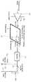
도 1은 본 발명의 실시 예에 따른 무선 전력 송수신 시스템의 개념도이다. 도 1에 도시된 바와 같이 무선 전력 송수신 시스템은 무선 전력 송신기(100) 및 무선 전력 수신기(110-1,110-2,110-n)를 포함할 수 있다. 무선 전력 송신기(100)는 무선 전력 수신기(110-1,110-2,110-n)와 전기적 연결을 형성할 수 있다. 도 1의 실시 예에서, 무선 전력 송신기(100)는 전자기파의 형태로 무선 전력을 무선 전력 수신기(110-1,110-2,110-n)로 공급할 수 있다.1 is a conceptual diagram of a wireless power transmission and reception system according to an embodiment of the present invention. As shown in FIG. 1, the wireless power transmission / reception system may include a
무선 전력 송신기(100)는 무선 전력 수신기(110-1,110-2,110-n)와 양방향 통신을 수행할 수 있다. 여기에서 무선 전력 송신기(100) 및 무선 전력 수신기(110-1,110-2,110-3,110-4)는 소정의 통신 패킷을 처리하거나 송수신할 수 있는 장치일 수 있으며, 예를 들어 핸드폰, PDA, PMP, 스마트폰 등으로 구현될 수 있다.The
무선 전력 송신기(100)는 복수 개의 무선 전력 수신기(110-1,110-2,110-n)로 무선으로 전력을 제공할 수 있다. 예를 들어 무선 전력 송신기(100)는 공진 방식을 통하여 복수 개의 무선 전력 수신기(110-1,110-2,110-n)에 전력을 전송할 수 있다.The
무선 전력 수신기(110-1,110-2,110-n)는 무선 전력 송신기(100)로부터 무선 전력을 수신하여 내부에 구비된 배터리의 충전을 수행할 수 있다. 또한 무선 전력 수신기(110-1,110-2,110-n)는 무선 전력 전송을 요청하는 신호나, 무선 전력 수신에 필요한 정보, 무선 전력 수신기 상태 정보 또는 무선 전력 송신기(100) 제어 정보 등을 무선 전력 송신기(100)에 송신할 수 있다. 상기의 송신 신호의 정보에 관하여서는 더욱 상세하게 후술하도록 한다.The wireless power receivers 110-1, 110-2, and 110-n may receive wireless power from the
아울러, 무선 전력 수신기(110-1,110-2,110-n)는 무선 전력 수신기(110-1,110-2,110-n)의 위치정보메시지를 송신할 수 있다. 여기에서 무선 전력 수신기(110-1,110-2,110-n)의 위치정보메시지는, RF신호 또는 블루투스와 같은 근거리 통신에 의하여 구현될 수 있으며, 이에 대하여서는 더욱 상세하게 후술하도록 한다.In addition, the wireless power receivers 110-1, 110-2, 110-n may transmit location information messages of the wireless power receivers 110-1, 110-2, 110-n. Here, the location information message of the wireless power receivers 110-1, 110-2, and 110-n may be implemented by short-range communication such as an RF signal or Bluetooth, which will be described later in more detail.
또한 무선 전력 수신기(110-1,110-2,110-n)는 각각의 충전상태를 나타내는 충전상태메시지를 무선 전력 송신기(100)로 송신할 수 있다.In addition, the wireless power receivers 110-1, 110-2, and 110-n may transmit charge state messages indicating respective charge states to the
무선 전력 송신기(100)는 디스플레이와 같은 표시수단을 포함할 수 있으며, 무선 전력 수신기(110-1,110-2,110-n) 각각으로부터 수신한 메시지에 기초하여 무선 전력 수신기(110-1,110-2,110-n) 각각의 상태를 표시할 수 있다. 아울러, 무선 전력 송신기(100)는 각각의 무선 전력 수신기(110-1,110-2,110-n)가 충전이 완료되기까지 예상되는 시간을 함께 표시할 수도 있다.The
한편, 무선 전력 송신기(100)는 무선 전력 수신기(110-1,110-2,110-n) 각각에 무선 충전 기능을 디스에이블(disabled)하도록 하는 제어 신호를 송신할 수도 있다. 무선 전력 송신기(100)로부터 무선 충전 기능의 디스에이블 제어 신호를 수신한 무선 전력 수신기는 무선 충전 기능을 디스에이블할 수 있다.Meanwhile, the
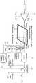
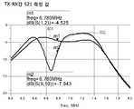
도 2a는 본 발명과의 비교를 위한 비교 예이다. 도 2a의 비교 예에 의한 무선 전력 송신기는 증폭부(201) 및 전력 송신부(211)를 포함한다. 아울러, 무선 전력 수신기는 전력 수신부(221), 정류부(222), 내부 저항(223), 외부 저항(224) 및 스위치부(225)를 포함한다. 증폭부(201)는 전력 공급부(미도시)로부터 VDD의 전압 및 IDD의 전류를 가지는 전력을 공급받으며, ω0의 교류로 변환하여 출력할 수 있으며, 예를 들어 6.78MHz일 수 있다. 증폭부(201)는 Class E Amp일 수 있다. 전력 송신부(211)는 전력을 무선으로 전력 수신부(221)로 송신하다. 정류부(222)는 수신된 전력을 정류한다. 한편, 충전 모드에서는 스위치부(225)가 온(on) 상태를 유지하며, 완충 모드에서는 스위치부(225)가 오프(off) 상태를 유지한다. 스위치부(225)가 온 상태인 경우에는 port 2에서 바라보는 임피던스가 10Ω이며, 스위치부(225)가 오프 상태인 경우에는 port 2에서 바라보는 임피던스가 135Ω이다. 상술한 바와 같은 임피던스 변경에 따라서, 도 2b와 같이 전력 송신부(221)로부터 전력 수신부(222)로의 전송 효율(S21)이 -1dB에서 -8dB로 감소할 수 있다.2A is a comparative example for comparison with the present invention. The wireless power transmitter according to the comparative example of FIG. 2A includes an
상술한 전송 효율 감소는 도 2c를 참조하여 설명한다. 도 2c의 좌측은 충전 모드에서의 무선 전력 송신기-수신기의 등가 회로이다. 등가회로는 접지(251), 일단이 접지(251)에 연결되는 저항(252), 일단이 저항(252)의 타단에 연결되는 로드(253), 일단이 로드(253)의 타단에 연결되는 로드(254) 및 일단이 로드(254)의 타단에 연결되는 저항(255)을 포함할 수 있다. 여기에서, 로드(253)의 임피던스는 50Ω이며, 로드(254)의 임피던스는 10Ω일 수 있다.The above-described transmission efficiency reduction will be described with reference to FIG. 2C. 2C is an equivalent circuit of the wireless power transmitter-receiver in the charging mode. The equivalent circuit includes a
한편, 도 2c의 우측은 완충 모드에서의 무선 전력 송신기-수신기의 등가 회로이다. 완충 모드에서는 로드(264)의 임피던스가 135Ω으로 증가하는 것을 확인할 수 있다. 이에 따라, 로드(253)으로부터 로드(264)로 인가되는 전력 중 일부가 반사(reflection)되며, 전체 전력 송수신 효율이 감소한다.On the other hand, the right side of Fig. 2C is an equivalent circuit of the wireless power transmitter-receiver in the buffer mode. In the buffer mode, it can be seen that the impedance of the
도 3은 본 발명의 실시 예에 따른 무선 전력 수신기의 블록도이다.3 is a block diagram of a wireless power receiver according to an embodiment of the present invention.
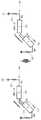
도 3에 도시된 바와 같이, 무선 전력 수신기(300)는 전력 수신부(301), 정류부(303), 스위치부(305), 로드부(307), 임피던스 조정부(309) 및 제어부(311)를 포함할 수 있다.As shown in FIG. 3, the
전력 수신부(301)는 무선 전력 송신기로부터 전력을 무선으로 수신할 수 있다. 전력 수신부(301)는, 예를 들어 소정의 인덕턴스를 가지는 루프 코일로 구현될 수 있다.The
전력 수신부(301)로부터 입력되는 전력은 정류부(303)로 출력될 수 있다.Power input from the
정류부(303)는 입력받은 전력을 정류할 수 있다. 정류부(303)는 공지된 정류 수단, 예를 들어 다이오드와 같은 수단으로 구현될 수 있으며, 정류를 할 수 있는 수단이라면 제한이 없음은 당업자가 용이하게 이해할 수 있을 것이다. 본 발명의 일 실시 예에 따른 정류부(303)는 풀 브리지 다이오드(full-bridge diode)의 형태로 구현될 수 있다. 정류부(303)는 입력된 교류 형태의 전력을 직류 형태의 전력으로 정류할 수 있다.The
정류부(303)는 스위치부(305)에 연결될 수 있으며, 스위치부(305)는 로드부(307) 및 정류부(303)의 연결을 온/오프할 수 있다.The
임피던스 조정부(309)는, 인덕터, 커패시터, 저항 중 적어도 하나를 포함할 수 있으며, 정류부(303)의 전단에 연결될 수 있다. 한편, 임피던스 조정부(309) 및 정류부(303) 사이에는 추가적으로 스위치부(미도시)가 포함될 수도 있으며, 제어부(311)의 제어에 따라서 임피던스 조정부(309)가 정류부(303)에 연결되거나 또는 연결되지 않을 수 있다. 예를 들어, 제어부(311)는, 스위치부(305)가 오프 상태인 경우에, 임피던스 조정부(309)가 정류부(303)에 연결되도록 제어할 수 있다. 상술한 인덕터의 인덕턴스, 커패시터의 커패시턴스, 저항의 레지스턴스는 변경 가능하다.The
한편, 임피던스 조정부(309)는 도 3에서는 정류부(303)의 전단에 연결된 것과 같이 도시되었지만, 정류부(303)의 후단에 연결될 수도 있다. 이러한 경우에, 정류부(303)는 적어도 하나의 저항을 포함할 수 있다. 상술한 저항의 레지스턴스는 변경 가능하다.Meanwhile, although the
제어부(311)는 무선 전력 수신기(300)의 동작 전반을 제어할 수 있다. 제어부(311)는 스위치부(305)의 온/오프 상태를 검출할 수 있다. 제어부(311)는 스위치부(305)가 온 상태를 유지하는 경우에는 임피던스 조정부(309)가 정류부(303)에 연결되지 않도록 제어한다. 예를 들어, 제어부(311)는 정류부(303) 및 임피던스 조정부(309) 사이에 배치되는 스위치부(미도시)를 오프 상태로 제어할 수 있다. 한편, 제어부(311)는 스위치부(305)가 오프 상태를 유지하는 경우에는 임피던스 조정부(309)가 정류부(303)에 연결되도록 제어한다. 예를 들어, 제어부(311)는 정류부(303) 및 임피던스 조정부(309) 상이에 배치되는 스위치부(미도시)를 온 상태로 제어할 수 있다.The
즉, 제어부(311)는 무선 전력 수신기(300)가 충전 모드로 작동하는 경우에는, 임피던스 조정부(309)를 정류부(303)에 연결하지 않도록 제어한다. 아울러, 제어부(311)는 무선 전력 수신기(300)가 완충 모드로 작동하는 경우에는, 임피던스 조정부(309)를 정류부(303)에 연결하도록 제어한다. 여기에서, 충전 모드는 CC(constant current) 모드일 수 있으며, 완충 모드는 CV(constant voltage) 모드일 수 있다.That is, the
임피던스 조정부(309)는 완충 모드인 경우에, 임피던스 매칭을 수행할 수 있으며, 이에 따라 완충 모드에서 증가되는 임피던스를 경감하여 충전 모드의 임피던스로 변경할 수 있다. 예를 들어, 임피던스 조정부(309)는 도 2c의 로드(264)의 임피던스를 10Ω으로 감소시킬 수 있으며, 이에 따라 전력 전송의 반사를 경감시킬 수 있다.In the case of the buffer mode, the
한편, 도시되지는 않았지만, 정류부(303) 및 로드부(307) 사이에는 레귤레이터부(regulator)부(미도시)가 배치될 수도 있다. 레귤레이터(regulator)부(미도시)는, 입력된 정류된 무선 전력로부터 리플(ripple)을 필터링하여 출력할 수 있다. 레귤레이터부(미도시)는 일 실시 예로, LC 필터로 구현될 수 있으며, 이에 따라 정류된 무선 전력을 더욱 직류 파형에 가깝게 보정할 수 있다. 또한 레귤레이터부(미도시)는, 출력단으로 무선 전력이 출력됨에 있어, 오버플로우(overflow) 등이 발생하지 않도록 무선 전력의 출력을 제어할 수도 있다. 레귤레이터부(미도시)에 의하여 출력되는 무선 전력은 외부로 출력되어 로드(load)로 인가되거나 또는 로드부(307)에 저장될 수 있다.Although not shown, a regulator part (not shown) may be disposed between the rectifying
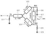
도 4a 및 4b는 무선 전력 수신기의 구현 예의 개념도이다.4A and 4B are conceptual diagrams of an example of implementation of a wireless power receiver.
도 4a 및 4b에 도시된 바와 같이, 무선 전력 송신기는 증폭부(401) 및 전력 송신부(411)를 포함한다. 아울러, 무선 전력 수신기는 전력 수신부(421), 정류부(422), 내부 저항(423), 외부 저항(424), 스위치부(425), 제어부(426), 스위치부(427), 인덕터부(428), 커패시터부(429) 및 접지부(430)를 포함한다.As shown in FIGS. 4A and 4B, the wireless power transmitter includes an
증폭부(401)는 전력 공급부(미도시)로부터 VDD의 전압 및 IDD의 전류를 가지는 전력을 공급받으며, ω0의 교류로 변환하여 출력할 수 있으며, 예를 들어 6.78MHz일 수 있다. 증폭부(201)는 Class E Amp일 수 있다. 전력 송신부(411)는 전력을 무선으로 전력 수신부(421)로 송신하다. 정류부(422)는 수신된 전력을 정류한다. 한편, 충전 모드에서는 스위치부(425)가 온(on) 상태를 유지하며, 완충 모드에서는 스위치부(425)가 오프(off) 상태를 유지한다. 스위치부(425)가 온 상태인 경우에는 port 2에서 바라보는 임피던스가 10Ω이며, 스위치부(425)가 오프 상태인 경우에는 port 2에서 바라보는 임피던스가 135Ω이다. 도 4a의 경우에서는, 스위치부(427)이 오프 상태를 유지하는 것을 확인할 수 있다. 제어부(426)는, 예를 들어 스위치부(425)의 온 상태를 검출하여, 스위치부(427)를 오프 상태로 제어할 수 있다.The
한편, 도 4b의 경우에서, 제어부(426)는 스위치부(425)가 오프 상태인 것을 확인하여 완충 모드인 것을 검출할 수 있다. 제어부(426)는 스위치부(427)를 온 상태로 제어할 수 있다. 스위치부(427)가 온 상태가 되면, 인덕터부(428), 커패시터부(429) 및 접지부(430)가 정류부(422)에 연결될 수 있다. 이에 따라서, port 2에서 바라보는 임피던스가 10Ω으로 조정될 수 있다. 여기에서, 인덕터부(428) 및 커패시터부(429)의 합성 임피던스는, 충전 모드에서의 port 2에서 바라본 임피던스, 예를 들어 10Ω 이상이면서, 완충 모드에서의 port 2에서 바라본 임피던스, 예를 들어 135Ω보다는 작을 수 있다.Meanwhile, in the case of FIG. 4B, the
한편, 인덕터부(428), 커패시터부(429) 이외에도 저항부가 추가적으로 구비될 수도 있다. 또한, 상술한 바와 같이, 정류부(422) 후단에도 병렬로 스위치 및 저항이 연결될 수도 있다. 아울러, 스위치가 온 상태인 경우에 저항에 의하여 임피던스가 조정될 수도 있다.Meanwhile, in addition to the
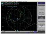
즉, 상술한 바와 같이, 완충 모드 또는 CV 모드에서 임피던스 증가를 임피던스 조정부에 기초하여 감소시킬 수 있다. 이에 따라, 도 5에 도시된 바와 같이 전송 효율(S21)이 -1dB에서 -3.2dB로 감소할 수 있다. 즉, 도 2b의 전송 효율이 -8dB인 것과 비교하여 전송 효율 감소의 문제가 완화된 것을 확인할 수 있다.That is, as described above, the impedance increase in the buffer mode or the CV mode can be reduced based on the impedance adjuster. Accordingly, as shown in FIG. 5, the transmission efficiency S21 may be reduced from -1 dB to -3.2 dB. That is, it can be seen that the problem of transmission efficiency reduction is alleviated compared to the transmission efficiency of -8dB in FIG. 2B.
도 6a는 본 발명과의 비교를 위한 비교 예이다. 도 6a의 비교 예에 의한 무선 전력 송신기는 증폭부(201) 및 전력 송신부(211)를 포함한다. 아울러, 제1 무선 전력 수신기는 전력 수신부(221), 정류부(222), 내부 저항(223), 외부 저항(224) 및 스위치부(225)를 포함한다. 또한 제2 무선 전력 수신기는 전력 수신부(251), 정류부(252), 내부 저항(253), 외부 저항(254) 및 스위치부(255)를 포함한다.6A is a comparative example for comparison with the present invention. The wireless power transmitter according to the comparative example of FIG. 6A includes an
증폭부(201)는 전력 공급부(미도시)로부터 VDD의 전압 및 IDD의 전류를 가지는 전력을 공급받으며, ω0의 교류로 변환하여 출력할 수 있으며, 예를 들어 6.78MHz일 수 있다. 증폭부(201)는 Class E Amp일 수 있다. 전력 송신부(211)는 전력을 무선으로 전력 수신부(221)로 송신하다. 정류부(222)는 수신된 전력을 정류한다. 한편, 충전 모드에서는 스위치부(225)가 온(on) 상태를 유지하며, 완충 모드에서는 스위치부(225)가 오프(off) 상태를 유지한다. 스위치부(225)가 온 상태인 경우에는 port 2에서 바라보는 임피던스가 10Ω이며, 스위치부(225)가 오프 상태인 경우에는 port 2에서 바라보는 임피던스가 135Ω이다.The
한편, 다른 전력 수신부(251) 또한 전력 송신부(211)로부터 전력을 무선으로 수신한다. 정류부(252)는 수신된 전력을 정류한다. 한편, 충전 모드에서는 스위치부(255)가 온(on) 상태를 유지하며, 완충 모드에서는 스위치부(255)가 오프(off) 상태를 유지한다. 스위치부(255)가 온 상태인 경우에는 port 2에서 바라보는 임피던스가 10Ω이며, 스위치부(255)가 오프 상태인 경우에는 port 2에서 바라보는 임피던스가 135Ω이다.Meanwhile, the
여기에서, 제1 무선 전력 수신기는 충전 모드이며, 제2 무선 전력 수신기가 완충 모드로 전환되는 상황을 상정하도록 한다.Here, it is assumed that the first wireless power receiver is in the charging mode and the second wireless power receiver is switched to the buffer mode.
제2 무선 전력 수신기가 완충 모드로 전환되어 제2 무선 전력 수신기의 자체 임피던스가 변경되는 경우에는, 제1 무선 전력 수신기의 임피던스에도 영향을 미친다. 아울러, 제2 무선 전력 수신기의 임피던스 변경은 제1 무선 전력 수신기의 전송 효율(S21)에도 영향을 미친다.If the second wireless power receiver is switched to the buffer mode to change its own impedance, the impedance of the first wireless power receiver is also affected. In addition, the impedance change of the second wireless power receiver also affects the transmission efficiency S21 of the first wireless power receiver.
도 6b는 제2 무선 전력 수신기의 자체 임피던스가 변경되는 경우의, 제1 무선 전력 수신기의 전송 효율(S21)의 그래프이다. 도 6b에서는, 전송 효율(S21)이 -4.5dB에서 -8dB로 감소하는 것을 확인할 수 있다. 즉, 제2 무선 전력 수신기의 자체 임피던스 변경이 제1 무선 전력 수신기의 전송 효율(S21)에도 영향을 미치는 것을 확인할 수 있다. 상술한 현상은 도 6c를 참조하여 설명하도록 한다.FIG. 6B is a graph of the transmission efficiency S21 of the first wireless power receiver when the self impedance of the second wireless power receiver is changed. In FIG. 6B, it can be seen that the transmission efficiency S21 decreases from -4.5 dB to -8 dB. That is, it can be seen that the change in the impedance of the second wireless power receiver affects the transmission efficiency S21 of the first wireless power receiver. The above phenomenon will be described with reference to FIG. 6C.
도 6c 충전 모드에서의 무선 전력 송신기-제1 수신기-제2 수신기의 등가 회로이다. 등가 회로는 일단이 접지되는 저항(611), 일단이 저항(611)의 타단에 연결되는 로드(612), 일단이 로드(612)의 타단에 연결되는 로드(613)과 일단이 로드(612)의 타단에 연결되는 로드(614)를 포함한다. 또한 로드(615)가 로드(613)의 타단 및 로드(614)의 타단 사이에 형성될 수 있다. 로드(615)는 제1 무선 전력 수신기 및 제2 무선 전력 수신기의 커플링(coupling)에 의하여 형성될 수 있다.6C is an equivalent circuit of a wireless power transmitter-first receiver-second receiver in a charging mode. The equivalent circuit includes a
한편, 저항(616)의 일단은 로드(613)에 연결되며, 타단은 접지(617)에 연결된다. 아울러, 저항(618)의 일단은 로드(614)에 연결되며, 타단은 접지(619)에 연결된다. 상술한 실시 예는, 제1 무선 전력 수신기가 충전 모드이며, 제2 무선 전력 수신기가 완충 모드인 경우를 상정하도록 한다. 로드(612)는 50Ω, 로드(613)는 10Ω, 로드(614)는 135Ω, 로드(615)는 50Ω일 수 있다.Meanwhile, one end of the
도 6d는 도 6c의 등가 회로이다. 도 6d에서, 접지(631)에는 저항(632)의 일단이 연결되며, 저항(632)의 타단에는 로드(633)의 일단이 연결된다. 로드(633)의 타단에는 로드(634)의 일단이 연결된다. 로드(634)의 타단에는 로드(635)의 일단 및 로드(636)의 일단이 연결된다. 로드(635)의 타단에는 저항(637)의 일단이 연결되며, 저항(637)의 타단은 접지(638)에 연결된다. 로드(636)의 타단에는 저항(639)의 일단이 연결되며, 저항(639)의 타단은 접지(640)에 연결된다. 여기에서, 로드(633)는 50Ω, 로드(634)는 6.92Ω, 로드(635)는 346Ω, 로드(636)는 2.56Ω일 수 있다.FIG. 6D is an equivalent circuit of FIG. 6C. In FIG. 6D, one end of the
도 6c의 로드들과 도 6d의 로드들은 하기 수학식 1 내지 3의 관계를 가진다.The rods of FIG. 6C and the rods of FIG. 6D have a relationship of


수학식 1 내지 3에서, Z1,Z2,Z3는 각각 도 6c의 로드(613), 로드(614) 및 로드(615)의 임피던스이다. 아울러, Z1',Z2',Z3'는 각각 도 6d의 로드(634), 로드(635) 및 로드(636)의 임피던스이다.In
한편, 도 6d에 도시된 바와 같이, 로드(635)의 임피던스는 도 6c의 로드(613)의 임피던스보다 증가하고, 이에 따라 제1 무선 전력 수신기의 전송 효율(S21)이 감소한다.Meanwhile, as shown in FIG. 6D, the impedance of the
도 6e 및 6f는 각각 제2 무선 전력 수신기가 충전 모드인 경우 및 제2 무선 전력 수신기가 완충 모드인 경우에 대응하는 제1 무선 전력 수신기의 송신 효율들이다. 도 6e 및 6f에 도시된 바와 같이, 제2 무선 전력 수신기의 자체 임피던스가 변경되는 경우에도 제1 무선 전력 수신기의 송신 효율이 변경될 수 있다.6E and 6F are transmission efficiencies of the first wireless power receiver, respectively, when the second wireless power receiver is in the charging mode and when the second wireless power receiver is in the buffer mode. As shown in FIGS. 6E and 6F, the transmission efficiency of the first wireless power receiver may be changed even when the impedance of the second wireless power receiver is changed.
이에 따라, 제2 무선 전력 수신기의 자체 임피던스가 변경되는 경우에도 제1 무선 전력 수신기의 송신 효율에 영향을 미치지 않도록 하는 기술 개발이 요청된다.Accordingly, there is a demand for a technology development that does not affect the transmission efficiency of the first wireless power receiver even when its own impedance of the second wireless power receiver is changed.
도 7a 및 7b는 본 발명의 실시 예에 따른 무선 전력 송신기-제1 무선 전력 수신기-제2 무선 전력 수신기의 개념도이다.7A and 7B are conceptual views illustrating a wireless power transmitter-first wireless power receiver-second wireless power receiver according to an embodiment of the present invention.
도 7a 및 7b에 도시된 바와 같이, 무선 전력 송신기는 증폭부(711) 및 전력 송신부(712)를 포함한다. 아울러, 제2 무선 전력 수신기는 전력 수신부(721), 정류부(722), 내부 저항(723), 외부 저항(724), 스위치부(725), 제어부(726), 스위치부(727), 인덕터부(728), 커패시터부(729) 및 접지부(730)를 포함한다. 제1 무선 전력 수신기는 전력 수신부(751), 정류부(752), 내부 저항(754), 외부 저항(756), 스위치부(753)를 포함한다.As shown in FIGS. 7A and 7B, the wireless power transmitter includes an
도 7a의 실시 예에서는, 제1 및 제2 무선 전력 수신기 모두 충전 모드인 경우를 상정하도록 한다.In the embodiment of FIG. 7A, it is assumed that both the first and second wireless power receivers are in the charging mode.
증폭부(711)는 전력 공급부(미도시)로부터 VDD의 전압 및 IDD의 전류를 가지는 전력을 공급받으며, ω0의 교류로 변환하여 출력할 수 있으며, 예를 들어 6.78MHz일 수 있다. 증폭부(711)는 Class E Amp일 수 있다. 전력 송신부(712)는 전력을 무선으로 전력 수신부(721) 및 전력 수신부(751)로 송신하다. 정류부(722,752)는 수신된 전력을 정류한다.The
한편, 충전 모드에서는 스위치부(725,753)가 온(on) 상태를 유지하며, 완충 모드에서는 스위치부(725,753)가 오프(off) 상태를 유지한다. 스위치부(725,753)가 온 상태인 경우에는 port 2에서 바라보는 임피던스가 10Ω이며, 스위치부(725,753)가 오프 상태인 경우에는 port 2에서 바라보는 임피던스가 135Ω이다.On the other hand, in the charging mode, the
도 7a의 경우에서는, 스위치부(727)이 오프 상태를 유지하는 것을 확인할 수 있다. 제어부(726)는, 예를 들어 스위치부(725)의 온 상태를 검출하여, 스위치부(727)를 오프 상태로 제어할 수 있다.In the case of FIG. 7A, it can be confirmed that the
한편, 도 7b의 경우에서, 제어부(726)는 스위치부(725)가 오프 상태인 것을 확인하여 완충 모드인 것을 검출할 수 있다. 제어부(726)는 스위치부(727)를 온 상태로 제어할 수 있다. 스위치부(727)가 온 상태가 되면, 인덕터부(728), 커패시터부(729) 및 접지부(730)가 정류부(722)에 연결될 수 있다. 이에 따라서, port 2에서 바라보는 임피던스가 10Ω으로 조정될 수 있다. 뿐만 아니라, 제2 무선 전력 수신기의 자체 임피던스가 재조정됨에 따라서, 제1 무선 전력 수신기의 전송 효율이 영향을 받지 않는다.Meanwhile, in the case of FIG. 7B, the
상술한 바는 도 7c 및 7d와 관련하여 설명하도록 한다. 도 7c 및 7d는 도 7b의 등가 회로이다.The foregoing will be described with reference to FIGS. 7C and 7D. 7C and 7D are equivalent circuits of FIG. 7B.
도 7c에 의한 등가 회로는 일단이 접지(771)에 연결되는 저항(772), 일단이 저항(772)의 타단에 연결되는 로드(773), 일단이 로드(773)의 타단에 연결되는 로드(774)과 일단이 로드(773)의 타단에 연결되는 로드(775)를 포함한다. 또한 로드(776)가 로드(774)의 타단 및 로드(775)의 타단 사이에 형성될 수 있다. 로드(776)는 제1 무선 전력 수신기 및 제2 무선 전력 수신기의 커플링(coupling)에 의하여 형성될 수 있다.The equivalent circuit of FIG. 7C includes a
한편, 저항(777)의 일단은 로드(774)에 연결되며, 타단은 접지(778)에 연결된다. 아울러, 저항(779)의 일단은 로드(775)에 연결되며, 타단은 접지(780)에 연결된다. 상술한 실시 예는, 제1 무선 전력 수신기가 충전 모드이며, 제2 무선 전력 수신기가 완충 모드인 경우이며, 임피던스 조정부가 연결된 상황을 상정하도록 한다. 로드(773)는 50Ω, 로드(774)는 10Ω, 로드(775)는 10Ω, 로드(776)는 50Ω일 수 있다. 즉, 로드(775)는 임피던스 조정부에 의하여 10Ω으로 임피던스가 변경될 수 있다.Meanwhile, one end of the
도 7d는 7c의 등가 회로이며, 상술한 바와 같은 수학식 1 내지 3에 의하여 형성될 수 있다. 도 7d에서, 접지(781)에는 저항(782)의 일단이 연결되며, 저항(782)의 타단에는 로드(783)의 일단이 연결된다. 로드(783)의 타단에는 로드(784)의 일단이 연결된다. 로드(784)의 타단에는 로드(785)의 일단 및 로드(788)의 일단이 연결된다. 로드(785)의 타단에는 저항(786)의 일단이 연결되며, 저항(786)의 타단은 접지(787)에 연결된다. 로드(788)의 타단에는 저항(789)의 일단이 연결되며, 저항(789)의 타단은 접지(790)에 연결된다. 여기에서, 로드(783)는 50Ω, 로드(784)는 1.42Ω, 로드(785)는 7.1Ω, 로드(788)는 7.1Ω일 수 있다. 여기에서, 로드(785) 및 로드(788)가 동일한 임피던스를 가지며, 이에 따라 제1 무선 젼력 수신기의 전송 효율 강하되는 문제가 완화될 수 있다.7D is an equivalent circuit of 7c, and may be formed by
도 8은 본 발명의 실시 예에 의한 제1 무선 전력 수신기의 전송 효율이다. 도 8에 도시된 바와 같이, 제2 무선 전력 수신기의 내부 임피던스가 변경되어도, 제1 무선 전력 수신기의 전송 효율은 -1dB에서 -1.5dB로 크게 영향받지 않는 것을 확인할 수 있다.8 is a transmission efficiency of the first wireless power receiver according to an embodiment of the present invention. As shown in FIG. 8, even when the internal impedance of the second wireless power receiver is changed, it may be confirmed that the transmission efficiency of the first wireless power receiver is not significantly affected from -1 dB to -1.5 dB.
이상에서는 본 발명의 바람직한 실시 예에 대하여 도시하고 설명하였지만, 당해 발명이 속하는 기술분야에서 통상의 지식을 가진 자라면, 누구든지 본 발명의 기술적 사상 및 범위를 벗어나지 않는 범주 내에서 본 발명의 바람직한 실시 예를 다양하게 변경할 수 있음은 물론이다. 따라서 본 발명은 특허청구범위에서 청구하는 본 발명의 요지를 벗어나지 않는다면 다양한 변형 실시가 가능할 것이며, 이러한 변형 실시들은 본 발명의 기술적 사상이나 전망으로부터 개별적으로 이해되어져서는 안될 것이다.While the present invention has been particularly shown and described with reference to exemplary embodiments thereof, it is clearly understood that the same is by way of illustration and example only and is not to be taken by way of illustration, It goes without saying that the example can be variously changed. Therefore, various modifications may be made without departing from the spirit of the invention as claimed in the claims, and such modifications should not be individually understood from the technical spirit or outlook of the invention.
Claims (11)
Translated fromKorean상기 무선 전력 송신기로부터 상기 구동 전력을 무선으로 수신하는 전력 수신부;
상기 전력 수신부로부터 출력되는 상기 구동 전력을 직류 형태로 정류하는 정류부;
상기 정류부로부터 출력되는 상기 정류된 구동 전력을 저장하는 로드부;
상기 로드부에 저장되는 구동 전력의 전력량을 검출하여, 상기 로드부로 출력되는 구동 전력의 전력량을 조정하는 제어부; 및
상기 로드부로 출력되는 구동 전력의 전력량에 따라서 상기 전력 수신부에서의 임피던스를 조정하는 임피던스 조정부;를 포함하는 것을 특징으로 하는 무선 전력 수신기.A wireless power receiver for wirelessly receiving driving power from a wireless power transmitter,
A power receiver wirelessly receiving the driving power from the wireless power transmitter;
A rectifier for rectifying the driving power output from the power receiver in a direct current form;
A load unit configured to store the rectified driving power output from the rectifier unit;
A control unit which detects the amount of driving power stored in the load unit and adjusts the amount of driving power output to the load unit; And
And an impedance adjusting unit for adjusting the impedance at the power receiving unit according to the amount of driving power output to the load unit.
상기 제어부는, 상기 로드부에 저장되는 구동 전력의 전력량이 CC(constant current) 모드에서 CV(constant voltage) 모드로 변경되는 것을 검출하는 것을 특징으로 하는 무선 전력 수신기.The method of claim 1,
The control unit is a wireless power receiver, characterized in that for detecting the amount of driving power stored in the load unit changes from the constant current (CC) mode to the constant voltage (CV) mode.
상기 제어부는, 상기 구동 전력의 전력량이 CC 모드에서 CV 모드로 변경되는 경우에, 임피던스 조정부가 상기 정류부의 전단 및 후단 중 적어도 하나에 연결되도록 제어하는 것을 특징으로 하는 무선 전력 수신기.The method of claim 2,
The controller may control the impedance adjusting unit to be connected to at least one of the front end and the rear end of the rectifier when the amount of power of the driving power is changed from the CC mode to the CV mode.
상기 임피던스 조정부와, 상기 정류부의 전단 및 후단 중 적어도 하나의 사이에 배치되는 적어도 하나의 스위치부;를 더 포함하며,
상기 제어부는, 상기 CC 모드에서는 상기 적어도 하나의 스위치부를 오프(off) 상태로 제어하며, 상기 CV 모드에서는 상기 적어도 하나의 스위치부를 온(on) 상태로 제어하는 것을 특징으로 하는 무선 전력 수신기.The method of claim 3, wherein
And at least one switch unit disposed between the impedance adjusting unit and at least one of a front end and a rear end of the rectifying unit.
The controller controls the at least one switch unit in an off state in the CC mode, and controls the at least one switch unit in an on state in the CV mode.
상기 임피던스 조정부는, 상기 CV 모드에서 상기 정류부의 전단에 연결되는 것을 특징으로 하는 무선 전력 수신기.The method of claim 3, wherein
The impedance adjusting unit is connected to the front end of the rectifier in the CV mode, the wireless power receiver.
상기 임피던스 조정부는, 커패시터, 코일 및 저항 중 적어도 하나를 포함하는 것을 특징으로 하는 무선 전력 수신기.The method of claim 5, wherein
The impedance adjusting unit, at least one of a capacitor, a coil and a resistor, characterized in that the wireless power receiver.
상기 임피던스 조정부는, 상기 커패시터, 코일 및 저항은 각각 가변 커패시터, 가변 코일 및 가변 저항인 것을 특징으로 하는 무선 전력 수신기.The method according to claim 6,
The impedance adjusting unit, the capacitor, the coil and the resistor is a wireless power receiver, characterized in that the variable capacitor, variable coil and variable resistor, respectively.
상기 임피던스 조정부는, 상기 CV 모드에서 상기 정류부의 후단에 연결되는 것을 특징으로 하는 무선 전력 수신기.The method of claim 3, wherein
The impedance adjusting unit is connected to the rear end of the rectifier in the CV mode, the wireless power receiver.
상기 저항은 가변 저항인 것을 특징으로 하는 무선 전력 수신기.The method of claim 9,
And the resistor is a variable resistor.
상기 임피던스 조정부는, 상기 CC 모드에서의 임피던스 및 상기 CV 모드에서의 상기 무선 전력 수신기의 임피던스가 동일하도록 조정하는 것을 특징으로 하는 무선 전력 수신기.The method of claim 2,
And the impedance adjusting unit adjusts the impedance of the CC mode and the impedance of the wireless power receiver in the CV mode to be the same.
Priority Applications (2)
| Application Number | Priority Date | Filing Date | Title |
|---|---|---|---|
| US13/548,660US9425629B2 (en) | 2011-07-14 | 2012-07-13 | Wireless power receiver |
| US15/241,887US9812893B2 (en) | 2011-07-14 | 2016-08-19 | Wireless power receiver |
Applications Claiming Priority (4)
| Application Number | Priority Date | Filing Date | Title |
|---|---|---|---|
| KR20110070120 | 2011-07-14 | ||
| KR1020110070120 | 2011-07-14 | ||
| KR1020110070603 | 2011-07-15 | ||
| KR20110070603 | 2011-07-15 |
Publications (2)
| Publication Number | Publication Date |
|---|---|
| KR20130009645Atrue KR20130009645A (en) | 2013-01-23 |
| KR101946848B1 KR101946848B1 (en) | 2019-02-13 |
Family
ID=47839348
Family Applications (1)
| Application Number | Title | Priority Date | Filing Date |
|---|---|---|---|
| KR1020120075383AExpired - Fee RelatedKR101946848B1 (en) | 2011-07-14 | 2012-07-11 | Wireless power receiver |
Country Status (1)
| Country | Link |
|---|---|
| KR (1) | KR101946848B1 (en) |
Cited By (1)
| Publication number | Priority date | Publication date | Assignee | Title |
|---|---|---|---|---|
| US10931145B2 (en) | 2015-04-27 | 2021-02-23 | Samsung Electronics Co., Ltd. | Wireless power receiver |
Families Citing this family (1)
| Publication number | Priority date | Publication date | Assignee | Title |
|---|---|---|---|---|
| KR102206189B1 (en)* | 2019-05-16 | 2021-01-22 | 주식회사대원농산 | Spawning device for Soldier Fly |
Citations (3)
| Publication number | Priority date | Publication date | Assignee | Title |
|---|---|---|---|---|
| US20050004564A1 (en)* | 2003-05-01 | 2005-01-06 | Wham Robert H. | Method and system for programming and controlling an electrosurgical generator system |
| US7656121B2 (en)* | 2007-02-22 | 2010-02-02 | Atmel Corporation | Soft transition from constant-current to a constant-voltage mode in a battery charger |
| US20100277121A1 (en)* | 2008-09-27 | 2010-11-04 | Hall Katherine L | Wireless energy transfer between a source and a vehicle |
- 2012
- 2012-07-11KRKR1020120075383Apatent/KR101946848B1/ennot_activeExpired - Fee Related
Patent Citations (3)
| Publication number | Priority date | Publication date | Assignee | Title |
|---|---|---|---|---|
| US20050004564A1 (en)* | 2003-05-01 | 2005-01-06 | Wham Robert H. | Method and system for programming and controlling an electrosurgical generator system |
| US7656121B2 (en)* | 2007-02-22 | 2010-02-02 | Atmel Corporation | Soft transition from constant-current to a constant-voltage mode in a battery charger |
| US20100277121A1 (en)* | 2008-09-27 | 2010-11-04 | Hall Katherine L | Wireless energy transfer between a source and a vehicle |
Cited By (1)
| Publication number | Priority date | Publication date | Assignee | Title |
|---|---|---|---|---|
| US10931145B2 (en) | 2015-04-27 | 2021-02-23 | Samsung Electronics Co., Ltd. | Wireless power receiver |
Also Published As
| Publication number | Publication date |
|---|---|
| KR101946848B1 (en) | 2019-02-13 |
Similar Documents
| Publication | Publication Date | Title |
|---|---|---|
| US9812893B2 (en) | Wireless power receiver | |
| KR101968519B1 (en) | Wireless power transmitter and method for controlling thereof | |
| US10205351B2 (en) | Wireless power transmitter, wireless power repeater and wireless power transmission method | |
| EP2587613B1 (en) | Wireless power receiver for adjusting magnitude of wireless power | |
| JP5804052B2 (en) | Wireless power receiving and receiving device and wireless power transmission system | |
| US9496083B2 (en) | Wireless power transmitter, wireless power receiver, and methods of controlling the same | |
| EP3557775A1 (en) | Wirelesspower transmitter for excluding cross-connected wireless power receiver and method for controlling the same | |
| KR20130048438A (en) | A wireless power transmission apparatus and method thereof | |
| KR101327049B1 (en) | A wireless power reception apparatus and a wireless charging system using the same | |
| KR20150057783A (en) | Apparatus and method for for wireless charge | |
| KR20130020437A (en) | Wireless power receiver for controlling wireless power by using switch | |
| CN103296786A (en) | Wireless power receiver and controlling method thereof | |
| KR102106476B1 (en) | Wireless power receiver | |
| US20140159673A1 (en) | Wireless charging apparatus and method | |
| KR20120116802A (en) | A wireless power transmission system and a wireless power receiver using a relay device | |
| KR20130032293A (en) | A wireless power reception apparatus and a wireless charging system using the same | |
| US9762293B2 (en) | Wireless power repeater and wireless power transmitter | |
| KR101946848B1 (en) | Wireless power receiver | |
| CN104218652A (en) | OLED flexible screen network electronic equipment powered by wireless charging | |
| CN104283334A (en) | Fingerprint identification electronic device with functions of wireless charging and wireless power supplying | |
| KR102115459B1 (en) | Apparatus and method for wireless charge | |
| KR101396497B1 (en) | Relay Device Using Wireless Power Transmission Apparatus | |
| KR101920216B1 (en) | Wireless power transmitter and wireless power receiver | |
| KR101745043B1 (en) | A wireless power transmission apparatus and method thereof | |
| KR101883655B1 (en) | Wireless power receiver and method for controlling thereof |
Legal Events
| Date | Code | Title | Description |
|---|---|---|---|
| PA0109 | Patent application | St.27 status event code:A-0-1-A10-A12-nap-PA0109 | |
| PG1501 | Laying open of application | St.27 status event code:A-1-1-Q10-Q12-nap-PG1501 | |
| P22-X000 | Classification modified | St.27 status event code:A-2-2-P10-P22-nap-X000 | |
| A201 | Request for examination | ||
| PA0201 | Request for examination | St.27 status event code:A-1-2-D10-D11-exm-PA0201 | |
| D13-X000 | Search requested | St.27 status event code:A-1-2-D10-D13-srh-X000 | |
| D14-X000 | Search report completed | St.27 status event code:A-1-2-D10-D14-srh-X000 | |
| P22-X000 | Classification modified | St.27 status event code:A-2-2-P10-P22-nap-X000 | |
| E902 | Notification of reason for refusal | ||
| PE0902 | Notice of grounds for rejection | St.27 status event code:A-1-2-D10-D21-exm-PE0902 | |
| P11-X000 | Amendment of application requested | St.27 status event code:A-2-2-P10-P11-nap-X000 | |
| P13-X000 | Application amended | St.27 status event code:A-2-2-P10-P13-nap-X000 | |
| E701 | Decision to grant or registration of patent right | ||
| PE0701 | Decision of registration | St.27 status event code:A-1-2-D10-D22-exm-PE0701 | |
| GRNT | Written decision to grant | ||
| PR0701 | Registration of establishment | St.27 status event code:A-2-4-F10-F11-exm-PR0701 | |
| PR1002 | Payment of registration fee | St.27 status event code:A-2-2-U10-U11-oth-PR1002 Fee payment year number:1 | |
| PG1601 | Publication of registration | St.27 status event code:A-4-4-Q10-Q13-nap-PG1601 | |
| P22-X000 | Classification modified | St.27 status event code:A-4-4-P10-P22-nap-X000 | |
| PC1903 | Unpaid annual fee | St.27 status event code:A-4-4-U10-U13-oth-PC1903 Not in force date:20220202 Payment event data comment text:Termination Category : DEFAULT_OF_REGISTRATION_FEE | |
| PC1903 | Unpaid annual fee | St.27 status event code:N-4-6-H10-H13-oth-PC1903 Ip right cessation event data comment text:Termination Category : DEFAULT_OF_REGISTRATION_FEE Not in force date:20220202 | |
| P22-X000 | Classification modified | St.27 status event code:A-4-4-P10-P22-nap-X000 |