KR20130007426A - Semiconductor device and manufacturing method thereof - Google Patents
Semiconductor device and manufacturing method thereofDownload PDFInfo
- Publication number
- KR20130007426A KR20130007426AKR1020120062491AKR20120062491AKR20130007426AKR 20130007426 AKR20130007426 AKR 20130007426AKR 1020120062491 AKR1020120062491 AKR 1020120062491AKR 20120062491 AKR20120062491 AKR 20120062491AKR 20130007426 AKR20130007426 AKR 20130007426A
- Authority
- KR
- South Korea
- Prior art keywords
- oxide semiconductor
- semiconductor layer
- layer
- oxide
- film
- Prior art date
- Legal status (The legal status is an assumption and is not a legal conclusion. Google has not performed a legal analysis and makes no representation as to the accuracy of the status listed.)
- Ceased
Links
- 239000004065semiconductorSubstances0.000titleclaimsabstractdescription471
- 238000004519manufacturing processMethods0.000titleclaimsabstractdescription18
- 238000000034methodMethods0.000claimsabstractdescription74
- 239000000758substrateSubstances0.000claimsdescription78
- 239000002019doping agentSubstances0.000claimsdescription37
- 239000010410layerSubstances0.000description405
- 239000010408filmSubstances0.000description335
- 239000000463materialSubstances0.000description51
- 239000004973liquid crystal related substanceSubstances0.000description42
- 239000001301oxygenSubstances0.000description42
- 229910052760oxygenInorganic materials0.000description42
- QVGXLLKOCUKJST-UHFFFAOYSA-Natomic oxygenChemical compound[O]QVGXLLKOCUKJST-UHFFFAOYSA-N0.000description38
- IJGRMHOSHXDMSA-UHFFFAOYSA-NAtomic nitrogenChemical compoundN#NIJGRMHOSHXDMSA-UHFFFAOYSA-N0.000description29
- 238000010438heat treatmentMethods0.000description29
- 239000013078crystalSubstances0.000description27
- 239000012535impuritySubstances0.000description26
- 239000011701zincSubstances0.000description20
- 239000007789gasSubstances0.000description19
- 238000004544sputter depositionMethods0.000description19
- 230000008569processEffects0.000description18
- 239000001257hydrogenSubstances0.000description17
- 229910052739hydrogenInorganic materials0.000description17
- 239000011229interlayerSubstances0.000description15
- 229910052751metalInorganic materials0.000description15
- 239000002184metalSubstances0.000description15
- 229910052757nitrogenInorganic materials0.000description15
- VYPSYNLAJGMNEJ-UHFFFAOYSA-Nsilicon dioxideInorganic materialsO=[Si]=OVYPSYNLAJGMNEJ-UHFFFAOYSA-N0.000description14
- UFHFLCQGNIYNRP-UHFFFAOYSA-NHydrogenChemical compound[H][H]UFHFLCQGNIYNRP-UHFFFAOYSA-N0.000description13
- 229910020994Sn-ZnInorganic materials0.000description12
- 229910009069Sn—ZnInorganic materials0.000description12
- 229910052782aluminiumInorganic materials0.000description12
- 238000010586diagramMethods0.000description12
- 238000003475laminationMethods0.000description12
- TWNQGVIAIRXVLR-UHFFFAOYSA-Noxo(oxoalumanyloxy)alumaneChemical compoundO=[Al]O[Al]=OTWNQGVIAIRXVLR-UHFFFAOYSA-N0.000description12
- 229920005989resinPolymers0.000description12
- 239000011347resinSubstances0.000description12
- XLOMVQKBTHCTTD-UHFFFAOYSA-NZinc monoxideChemical compound[Zn]=OXLOMVQKBTHCTTD-UHFFFAOYSA-N0.000description11
- 238000005530etchingMethods0.000description11
- 230000006870functionEffects0.000description11
- 238000005468ion implantationMethods0.000description11
- 239000002245particleSubstances0.000description11
- 239000012071phaseSubstances0.000description11
- XKRFYHLGVUSROY-UHFFFAOYSA-NArgonChemical compound[Ar]XKRFYHLGVUSROY-UHFFFAOYSA-N0.000description10
- GQPLMRYTRLFLPF-UHFFFAOYSA-NNitrous OxideChemical compound[O-][N+]#NGQPLMRYTRLFLPF-UHFFFAOYSA-N0.000description10
- XAGFODPZIPBFFR-UHFFFAOYSA-NaluminiumChemical compound[Al]XAGFODPZIPBFFR-UHFFFAOYSA-N0.000description10
- 229910021417amorphous siliconInorganic materials0.000description10
- 238000005401electroluminescenceMethods0.000description10
- -1oxygen radicalsChemical class0.000description10
- 229910052814silicon oxideInorganic materials0.000description10
- 239000000203mixtureSubstances0.000description9
- 229910052721tungstenInorganic materials0.000description9
- XUIMIQQOPSSXEZ-UHFFFAOYSA-NSiliconChemical compound[Si]XUIMIQQOPSSXEZ-UHFFFAOYSA-N0.000description8
- 229910052796boronInorganic materials0.000description8
- 229910052710siliconInorganic materials0.000description8
- 239000010703siliconSubstances0.000description8
- 239000002356single layerSubstances0.000description8
- ZOXJGFHDIHLPTG-UHFFFAOYSA-NBoronChemical compound[B]ZOXJGFHDIHLPTG-UHFFFAOYSA-N0.000description7
- 229910052581Si3N4Inorganic materials0.000description7
- 230000015572biosynthetic processEffects0.000description7
- 239000011521glassSubstances0.000description7
- 150000004767nitridesChemical class0.000description7
- 238000005268plasma chemical vapour depositionMethods0.000description7
- HQVNEWCFYHHQES-UHFFFAOYSA-Nsilicon nitrideChemical compoundN12[Si]34N5[Si]62N3[Si]51N64HQVNEWCFYHHQES-UHFFFAOYSA-N0.000description7
- 239000010937tungstenSubstances0.000description7
- XLYOFNOQVPJJNP-UHFFFAOYSA-NwaterSubstancesOXLYOFNOQVPJJNP-UHFFFAOYSA-N0.000description7
- 229910001868waterInorganic materials0.000description7
- 230000000903blocking effectEffects0.000description6
- 230000005669field effectEffects0.000description6
- 229910003437indium oxideInorganic materials0.000description6
- PJXISJQVUVHSOJ-UHFFFAOYSA-Nindium(iii) oxideChemical compound[O-2].[O-2].[O-2].[In+3].[In+3]PJXISJQVUVHSOJ-UHFFFAOYSA-N0.000description6
- 239000011810insulating materialSubstances0.000description6
- 150000002500ionsChemical class0.000description6
- 229910044991metal oxideInorganic materials0.000description6
- 150000004706metal oxidesChemical class0.000description6
- 239000010936titaniumSubstances0.000description6
- 239000004925Acrylic resinSubstances0.000description5
- 229920000178Acrylic resinPolymers0.000description5
- MYMOFIZGZYHOMD-UHFFFAOYSA-NDioxygenChemical compoundO=OMYMOFIZGZYHOMD-UHFFFAOYSA-N0.000description5
- 229910052786argonInorganic materials0.000description5
- 239000012298atmosphereSubstances0.000description5
- 239000000460chlorineSubstances0.000description5
- 229910052802copperInorganic materials0.000description5
- 239000010949copperSubstances0.000description5
- 238000000151depositionMethods0.000description5
- 229910001882dioxygenInorganic materials0.000description5
- 239000000945fillerSubstances0.000description5
- 229910052735hafniumInorganic materials0.000description5
- AMGQUBHHOARCQH-UHFFFAOYSA-Nindium;oxotinChemical compound[In].[Sn]=OAMGQUBHHOARCQH-UHFFFAOYSA-N0.000description5
- 238000010030laminatingMethods0.000description5
- 229960001730nitrous oxideDrugs0.000description5
- 235000013842nitrous oxideNutrition0.000description5
- 239000000123paperSubstances0.000description5
- 230000003071parasitic effectEffects0.000description5
- 230000001681protective effectEffects0.000description5
- 239000003566sealing materialSubstances0.000description5
- 239000003381stabilizerSubstances0.000description5
- 229910052719titaniumInorganic materials0.000description5
- WFKWXMTUELFFGS-UHFFFAOYSA-NtungstenChemical compound[W]WFKWXMTUELFFGS-UHFFFAOYSA-N0.000description5
- 239000011787zinc oxideSubstances0.000description5
- CURLTUGMZLYLDI-UHFFFAOYSA-NCarbon dioxideChemical compoundO=C=OCURLTUGMZLYLDI-UHFFFAOYSA-N0.000description4
- OAICVXFJPJFONN-UHFFFAOYSA-NPhosphorusChemical compound[P]OAICVXFJPJFONN-UHFFFAOYSA-N0.000description4
- GWEVSGVZZGPLCZ-UHFFFAOYSA-NTitan oxideChemical compoundO=[Ti]=OGWEVSGVZZGPLCZ-UHFFFAOYSA-N0.000description4
- 229910052804chromiumInorganic materials0.000description4
- 239000011651chromiumSubstances0.000description4
- 230000000694effectsEffects0.000description4
- VBJZVLUMGGDVMO-UHFFFAOYSA-Nhafnium atomChemical compound[Hf]VBJZVLUMGGDVMO-UHFFFAOYSA-N0.000description4
- 150000002431hydrogenChemical class0.000description4
- 229910052738indiumInorganic materials0.000description4
- 239000011261inert gasSubstances0.000description4
- 239000000976inkSubstances0.000description4
- 239000003094microcapsuleSubstances0.000description4
- 229910052750molybdenumInorganic materials0.000description4
- QGLKJKCYBOYXKC-UHFFFAOYSA-NnonaoxidotritungstenChemical compoundO=[W]1(=O)O[W](=O)(=O)O[W](=O)(=O)O1QGLKJKCYBOYXKC-UHFFFAOYSA-N0.000description4
- 230000003287optical effectEffects0.000description4
- 150000002894organic compoundsChemical class0.000description4
- 239000011368organic materialSubstances0.000description4
- 229910052698phosphorusInorganic materials0.000description4
- 239000011574phosphorusSubstances0.000description4
- 229920001721polyimidePolymers0.000description4
- 239000009719polyimide resinSubstances0.000description4
- 239000010453quartzSubstances0.000description4
- 230000004044responseEffects0.000description4
- OGIDPMRJRNCKJF-UHFFFAOYSA-Ntitanium oxideInorganic materials[Ti]=OOGIDPMRJRNCKJF-UHFFFAOYSA-N0.000description4
- 229910001930tungsten oxideInorganic materials0.000description4
- QTBSBXVTEAMEQO-UHFFFAOYSA-NAcetic acidChemical compoundCC(O)=OQTBSBXVTEAMEQO-UHFFFAOYSA-N0.000description3
- 229910018137Al-ZnInorganic materials0.000description3
- 229910018573Al—ZnInorganic materials0.000description3
- RYGMFSIKBFXOCR-UHFFFAOYSA-NCopperChemical compound[Cu]RYGMFSIKBFXOCR-UHFFFAOYSA-N0.000description3
- 229910003902SiCl 4Inorganic materials0.000description3
- BLRPTPMANUNPDV-UHFFFAOYSA-NSilaneChemical compound[SiH4]BLRPTPMANUNPDV-UHFFFAOYSA-N0.000description3
- 229910007541Zn OInorganic materials0.000description3
- 238000000231atomic layer depositionMethods0.000description3
- UMIVXZPTRXBADB-UHFFFAOYSA-NbenzocyclobuteneChemical compoundC1=CC=C2CCC2=C1UMIVXZPTRXBADB-UHFFFAOYSA-N0.000description3
- 239000003990capacitorSubstances0.000description3
- SLLGVCUQYRMELA-UHFFFAOYSA-NchlorosiliconChemical compoundCl[Si]SLLGVCUQYRMELA-UHFFFAOYSA-N0.000description3
- 239000004020conductorSubstances0.000description3
- 230000008021depositionEffects0.000description3
- AJNVQOSZGJRYEI-UHFFFAOYSA-Ndigallium;oxygen(2-)Chemical compound[O-2].[O-2].[O-2].[Ga+3].[Ga+3]AJNVQOSZGJRYEI-UHFFFAOYSA-N0.000description3
- 230000005684electric fieldEffects0.000description3
- 239000003822epoxy resinSubstances0.000description3
- 239000005262ferroelectric liquid crystals (FLCs)Substances0.000description3
- 229910001195gallium oxideInorganic materials0.000description3
- 238000007654immersionMethods0.000description3
- 238000004518low pressure chemical vapour depositionMethods0.000description3
- 230000007246mechanismEffects0.000description3
- 238000001451molecular beam epitaxyMethods0.000description3
- 229910052754neonInorganic materials0.000description3
- GKAOGPIIYCISHV-UHFFFAOYSA-Nneon atomChemical compound[Ne]GKAOGPIIYCISHV-UHFFFAOYSA-N0.000description3
- 125000004430oxygen atomChemical groupO*0.000description3
- 238000000206photolithographyMethods0.000description3
- 229920003023plasticPolymers0.000description3
- 239000004033plasticSubstances0.000description3
- 229920000647polyepoxidePolymers0.000description3
- 229920002620polyvinyl fluoridePolymers0.000description3
- 229910000077silaneInorganic materials0.000description3
- 238000005477sputtering targetMethods0.000description3
- MZLGASXMSKOWSE-UHFFFAOYSA-Ntantalum nitrideChemical compound[Ta]#NMZLGASXMSKOWSE-UHFFFAOYSA-N0.000description3
- 238000002834transmittanceMethods0.000description3
- 238000001947vapour-phase growthMethods0.000description3
- 238000001039wet etchingMethods0.000description3
- 229910052725zincInorganic materials0.000description3
- YVTHLONGBIQYBO-UHFFFAOYSA-Nzinc indium(3+) oxygen(2-)Chemical compound[O--].[Zn++].[In+3]YVTHLONGBIQYBO-UHFFFAOYSA-N0.000description3
- OKTJSMMVPCPJKN-UHFFFAOYSA-NCarbonChemical compound[C]OKTJSMMVPCPJKN-UHFFFAOYSA-N0.000description2
- 229910005191Ga 2 O 3Inorganic materials0.000description2
- 206010021143HypoxiaDiseases0.000description2
- ZOKXTWBITQBERF-UHFFFAOYSA-NMolybdenumChemical compound[Mo]ZOKXTWBITQBERF-UHFFFAOYSA-N0.000description2
- BPQQTUXANYXVAA-UHFFFAOYSA-NOrthosilicateChemical compound[O-][Si]([O-])([O-])[O-]BPQQTUXANYXVAA-UHFFFAOYSA-N0.000description2
- NBIIXXVUZAFLBC-UHFFFAOYSA-NPhosphoric acidChemical compoundOP(O)(O)=ONBIIXXVUZAFLBC-UHFFFAOYSA-N0.000description2
- 229910006404SnO 2Inorganic materials0.000description2
- ATJFFYVFTNAWJD-UHFFFAOYSA-NTinChemical compound[Sn]ATJFFYVFTNAWJD-UHFFFAOYSA-N0.000description2
- RTAQQCXQSZGOHL-UHFFFAOYSA-NTitaniumChemical compound[Ti]RTAQQCXQSZGOHL-UHFFFAOYSA-N0.000description2
- NRTOMJZYCJJWKI-UHFFFAOYSA-NTitanium nitrideChemical compound[Ti]#NNRTOMJZYCJJWKI-UHFFFAOYSA-N0.000description2
- 230000001133accelerationEffects0.000description2
- 230000009471actionEffects0.000description2
- 239000012790adhesive layerSubstances0.000description2
- 125000004429atomChemical group0.000description2
- GPBUGPUPKAGMDK-UHFFFAOYSA-NazanylidynemolybdenumChemical compound[Mo]#NGPBUGPUPKAGMDK-UHFFFAOYSA-N0.000description2
- 239000005380borophosphosilicate glassSubstances0.000description2
- DQXBYHZEEUGOBF-UHFFFAOYSA-Nbut-3-enoic acid;etheneChemical compoundC=C.OC(=O)CC=CDQXBYHZEEUGOBF-UHFFFAOYSA-N0.000description2
- 239000001569carbon dioxideSubstances0.000description2
- 229910002092carbon dioxideInorganic materials0.000description2
- 230000003098cholesteric effectEffects0.000description2
- 230000007547defectEffects0.000description2
- 238000013461designMethods0.000description2
- 238000009792diffusion processMethods0.000description2
- KPUWHANPEXNPJT-UHFFFAOYSA-NdisiloxaneChemical class[SiH3]O[SiH3]KPUWHANPEXNPJT-UHFFFAOYSA-N0.000description2
- 238000001312dry etchingMethods0.000description2
- 230000009977dual effectEffects0.000description2
- 230000005611electricityEffects0.000description2
- 239000005038ethylene vinyl acetateSubstances0.000description2
- 230000005281excited stateEffects0.000description2
- 239000011152fibreglassSubstances0.000description2
- 229910000449hafnium oxideInorganic materials0.000description2
- WIHZLLGSGQNAGK-UHFFFAOYSA-Nhafnium(4+);oxygen(2-)Chemical compound[O-2].[O-2].[Hf+4]WIHZLLGSGQNAGK-UHFFFAOYSA-N0.000description2
- 229910052734heliumInorganic materials0.000description2
- 239000001307heliumSubstances0.000description2
- SWQJXJOGLNCZEY-UHFFFAOYSA-Nhelium atomChemical compound[He]SWQJXJOGLNCZEY-UHFFFAOYSA-N0.000description2
- MYMOFIZGZYHOMD-UHFFFAOYSA-Ohydridodioxygen(1+)Chemical compound[OH+]=OMYMOFIZGZYHOMD-UHFFFAOYSA-O0.000description2
- APFVFJFRJDLVQX-UHFFFAOYSA-Nindium atomChemical compound[In]APFVFJFRJDLVQX-UHFFFAOYSA-N0.000description2
- 238000002347injectionMethods0.000description2
- 239000007924injectionSubstances0.000description2
- 238000012905input functionMethods0.000description2
- MRELNEQAGSRDBK-UHFFFAOYSA-Nlanthanum(3+);oxygen(2-)Chemical compound[O-2].[O-2].[O-2].[La+3].[La+3]MRELNEQAGSRDBK-UHFFFAOYSA-N0.000description2
- 239000007769metal materialSubstances0.000description2
- 239000011733molybdenumSubstances0.000description2
- 239000010955niobiumSubstances0.000description2
- 239000012299nitrogen atmosphereSubstances0.000description2
- 238000002294plasma sputter depositionMethods0.000description2
- 238000009832plasma treatmentMethods0.000description2
- 229920001200poly(ethylene-vinyl acetate)Polymers0.000description2
- 229920002037poly(vinyl butyral) polymerPolymers0.000description2
- 229920006122polyamide resinPolymers0.000description2
- 229920006267polyester filmPolymers0.000description2
- 229920000915polyvinyl chloridePolymers0.000description2
- 239000004800polyvinyl chlorideSubstances0.000description2
- 230000005855radiationEffects0.000description2
- 238000004151rapid thermal annealingMethods0.000description2
- HBMJWWWQQXIZIP-UHFFFAOYSA-Nsilicon carbideChemical compound[Si+]#[C-]HBMJWWWQQXIZIP-UHFFFAOYSA-N0.000description2
- 229910010271silicon carbideInorganic materials0.000description2
- 239000000243solutionSubstances0.000description2
- 239000002904solventSubstances0.000description2
- 125000006850spacer groupChemical group0.000description2
- 230000003068static effectEffects0.000description2
- 229910052715tantalumInorganic materials0.000description2
- JBQYATWDVHIOAR-UHFFFAOYSA-NtellanylidenegermaniumChemical compound[Te]=[Ge]JBQYATWDVHIOAR-UHFFFAOYSA-N0.000description2
- XOLBLPGZBRYERU-UHFFFAOYSA-Ntin dioxideChemical compoundO=[Sn]=OXOLBLPGZBRYERU-UHFFFAOYSA-N0.000description2
- 229910001887tin oxideInorganic materials0.000description2
- 238000004402ultra-violet photoelectron spectroscopyMethods0.000description2
- 210000003462veinAnatomy0.000description2
- UWCWUCKPEYNDNV-LBPRGKRZSA-N2,6-dimethyl-n-[[(2s)-pyrrolidin-2-yl]methyl]anilineChemical compoundCC1=CC=CC(C)=C1NC[C@H]1NCCC1UWCWUCKPEYNDNV-LBPRGKRZSA-N0.000description1
- 229910052684CeriumInorganic materials0.000description1
- VEXZGXHMUGYJMC-UHFFFAOYSA-MChloride anionChemical compound[Cl-]VEXZGXHMUGYJMC-UHFFFAOYSA-M0.000description1
- ZAMOUSCENKQFHK-UHFFFAOYSA-NChlorine atomChemical compound[Cl]ZAMOUSCENKQFHK-UHFFFAOYSA-N0.000description1
- 239000004986Cholesteric liquid crystals (ChLC)Substances0.000description1
- VYZAMTAEIAYCRO-UHFFFAOYSA-NChromiumChemical compound[Cr]VYZAMTAEIAYCRO-UHFFFAOYSA-N0.000description1
- 229910052691ErbiumInorganic materials0.000description1
- 229910052693EuropiumInorganic materials0.000description1
- KRHYYFGTRYWZRS-UHFFFAOYSA-MFluoride anionChemical compound[F-]KRHYYFGTRYWZRS-UHFFFAOYSA-M0.000description1
- PXGOKWXKJXAPGV-UHFFFAOYSA-NFluorineChemical compoundFFPXGOKWXKJXAPGV-UHFFFAOYSA-N0.000description1
- 229910052688GadoliniumInorganic materials0.000description1
- GYHNNYVSQQEPJS-UHFFFAOYSA-NGalliumChemical compound[Ga]GYHNNYVSQQEPJS-UHFFFAOYSA-N0.000description1
- 206010052128GlareDiseases0.000description1
- 229910004129HfSiOInorganic materials0.000description1
- 239000005264High molar mass liquid crystalSubstances0.000description1
- 229910052689HolmiumInorganic materials0.000description1
- DGAQECJNVWCQMB-PUAWFVPOSA-MIlexoside XXIXChemical compoundC[C@@H]1CC[C@@]2(CC[C@@]3(C(=CC[C@H]4[C@]3(CC[C@@H]5[C@@]4(CC[C@@H](C5(C)C)OS(=O)(=O)[O-])C)C)[C@@H]2[C@]1(C)O)C)C(=O)O[C@H]6[C@@H]([C@H]([C@@H]([C@H](O6)CO)O)O)O.[Na+]DGAQECJNVWCQMB-PUAWFVPOSA-M0.000description1
- 229910052765LutetiumInorganic materials0.000description1
- 229910052779NeodymiumInorganic materials0.000description1
- GRYLNZFGIOXLOG-UHFFFAOYSA-NNitric acidChemical compoundO[N+]([O-])=OGRYLNZFGIOXLOG-UHFFFAOYSA-N0.000description1
- 239000004983Polymer Dispersed Liquid CrystalSubstances0.000description1
- 229910052772SamariumInorganic materials0.000description1
- 229910004298SiO 2Inorganic materials0.000description1
- 229910000577Silicon-germaniumInorganic materials0.000description1
- 239000004990Smectic liquid crystalSubstances0.000description1
- 229910020833Sn-Al-ZnInorganic materials0.000description1
- 229910020868Sn-Ga-ZnInorganic materials0.000description1
- 229910020923Sn-OInorganic materials0.000description1
- 229910052771TerbiumInorganic materials0.000description1
- 239000004974Thermotropic liquid crystalSubstances0.000description1
- 229910052775ThuliumInorganic materials0.000description1
- 229910052769YtterbiumInorganic materials0.000description1
- HCHKCACWOHOZIP-UHFFFAOYSA-NZincChemical compound[Zn]HCHKCACWOHOZIP-UHFFFAOYSA-N0.000description1
- LEVVHYCKPQWKOP-UHFFFAOYSA-N[Si].[Ge]Chemical compound[Si].[Ge]LEVVHYCKPQWKOP-UHFFFAOYSA-N0.000description1
- AZWHFTKIBIQKCA-UHFFFAOYSA-N[Sn+2]=O.[O-2].[In+3]Chemical compound[Sn+2]=O.[O-2].[In+3]AZWHFTKIBIQKCA-UHFFFAOYSA-N0.000description1
- 239000000956alloySubstances0.000description1
- 229910000147aluminium phosphateInorganic materials0.000description1
- 239000005407aluminoborosilicate glassSubstances0.000description1
- 229910052787antimonyInorganic materials0.000description1
- WATWJIUSRGPENY-UHFFFAOYSA-Nantimony atomChemical compound[Sb]WATWJIUSRGPENY-UHFFFAOYSA-N0.000description1
- 229910052785arsenicInorganic materials0.000description1
- RQNWIZPPADIBDY-UHFFFAOYSA-Narsenic atomChemical compound[As]RQNWIZPPADIBDY-UHFFFAOYSA-N0.000description1
- 229910052788bariumInorganic materials0.000description1
- DSAJWYNOEDNPEQ-UHFFFAOYSA-Nbarium atomChemical compound[Ba]DSAJWYNOEDNPEQ-UHFFFAOYSA-N0.000description1
- 230000004888barrier functionEffects0.000description1
- 230000008901benefitEffects0.000description1
- 230000002457bidirectional effectEffects0.000description1
- 239000005388borosilicate glassSubstances0.000description1
- 239000002775capsuleSubstances0.000description1
- 229910052799carbonInorganic materials0.000description1
- 239000000969carrierSubstances0.000description1
- 230000015556catabolic processEffects0.000description1
- 239000000919ceramicSubstances0.000description1
- 230000008859changeEffects0.000description1
- 238000005229chemical vapour depositionMethods0.000description1
- 229910052801chlorineInorganic materials0.000description1
- 239000003086colorantSubstances0.000description1
- 238000004891communicationMethods0.000description1
- 239000002131composite materialSubstances0.000description1
- 150000001875compoundsChemical class0.000description1
- 239000000470constituentSubstances0.000description1
- 239000013256coordination polymerSubstances0.000description1
- PMHQVHHXPFUNSP-UHFFFAOYSA-Mcopper(1+);methylsulfanylmethane;bromideChemical compoundBr[Cu].CSCPMHQVHHXPFUNSP-UHFFFAOYSA-M0.000description1
- 238000007872degassingMethods0.000description1
- 230000018044dehydrationEffects0.000description1
- 238000006297dehydration reactionMethods0.000description1
- 238000006356dehydrogenation reactionMethods0.000description1
- 238000001514detection methodMethods0.000description1
- 238000011161developmentMethods0.000description1
- 238000007598dipping methodMethods0.000description1
- 230000005685electric field effectEffects0.000description1
- UYAHIZSMUZPPFV-UHFFFAOYSA-NerbiumChemical compound[Er]UYAHIZSMUZPPFV-UHFFFAOYSA-N0.000description1
- 238000000605extractionMethods0.000description1
- 239000004744fabricSubstances0.000description1
- 229910052731fluorineInorganic materials0.000description1
- 239000011737fluorineSubstances0.000description1
- 239000011888foilSubstances0.000description1
- 229910052733galliumInorganic materials0.000description1
- 229910021389grapheneInorganic materials0.000description1
- 230000005283ground stateEffects0.000description1
- 229910052736halogenInorganic materials0.000description1
- 150000002367halogensChemical class0.000description1
- KJZYNXUDTRRSPN-UHFFFAOYSA-Nholmium atomChemical compound[Ho]KJZYNXUDTRRSPN-UHFFFAOYSA-N0.000description1
- 150000004678hydridesChemical class0.000description1
- BHEPBYXIRTUNPN-UHFFFAOYSA-Nhydridophosphorus(.) (triplet)Chemical compound[PH]BHEPBYXIRTUNPN-UHFFFAOYSA-N0.000description1
- 125000002887hydroxy groupChemical group[H]O*0.000description1
- 238000002513implantationMethods0.000description1
- 150000002484inorganic compoundsChemical class0.000description1
- 229910010272inorganic materialInorganic materials0.000description1
- 239000012212insulatorSubstances0.000description1
- 229910052747lanthanoidInorganic materials0.000description1
- 150000002602lanthanoidsChemical class0.000description1
- 229910052746lanthanumInorganic materials0.000description1
- 238000001307laser spectroscopyMethods0.000description1
- 238000001459lithographyMethods0.000description1
- OHSVLFRHMCKCQY-UHFFFAOYSA-Nlutetium atomChemical compound[Lu]OHSVLFRHMCKCQY-UHFFFAOYSA-N0.000description1
- 239000000696magnetic materialSubstances0.000description1
- 239000011159matrix materialSubstances0.000description1
- 238000005259measurementMethods0.000description1
- QSHDDOUJBYECFT-UHFFFAOYSA-NmercuryChemical compound[Hg]QSHDDOUJBYECFT-UHFFFAOYSA-N0.000description1
- 229910052753mercuryInorganic materials0.000description1
- 229910001507metal halideInorganic materials0.000description1
- 150000005309metal halidesChemical class0.000description1
- 238000002156mixingMethods0.000description1
- 229910021421monocrystalline siliconInorganic materials0.000description1
- 239000000178monomerSubstances0.000description1
- QEFYFXOXNSNQGX-UHFFFAOYSA-Nneodymium atomChemical compound[Nd]QEFYFXOXNSNQGX-UHFFFAOYSA-N0.000description1
- 229910052759nickelInorganic materials0.000description1
- PXHVJJICTQNCMI-UHFFFAOYSA-NnickelSubstances[Ni]PXHVJJICTQNCMI-UHFFFAOYSA-N0.000description1
- RUFLMLWJRZAWLJ-UHFFFAOYSA-Nnickel silicideChemical compound[Ni]=[Si]=[Ni]RUFLMLWJRZAWLJ-UHFFFAOYSA-N0.000description1
- 229910021334nickel silicideInorganic materials0.000description1
- 229910052758niobiumInorganic materials0.000description1
- GUCVJGMIXFAOAE-UHFFFAOYSA-Nniobium atomChemical compound[Nb]GUCVJGMIXFAOAE-UHFFFAOYSA-N0.000description1
- 229910017604nitric acidInorganic materials0.000description1
- QJGQUHMNIGDVPM-UHFFFAOYSA-Nnitrogen groupChemical group[N]QJGQUHMNIGDVPM-UHFFFAOYSA-N0.000description1
- 238000007645offset printingMethods0.000description1
- 239000012788optical filmSubstances0.000description1
- SIWVEOZUMHYXCS-UHFFFAOYSA-Noxo(oxoyttriooxy)yttriumChemical compoundO=[Y]O[Y]=OSIWVEOZUMHYXCS-UHFFFAOYSA-N0.000description1
- 238000005192partitionMethods0.000description1
- 230000002093peripheral effectEffects0.000description1
- 239000000049pigmentSubstances0.000description1
- 229910052697platinumInorganic materials0.000description1
- BASFCYQUMIYNBI-UHFFFAOYSA-NplatinumSubstances[Pt]BASFCYQUMIYNBI-UHFFFAOYSA-N0.000description1
- 229910052696pnictogenInorganic materials0.000description1
- 229910021420polycrystalline siliconInorganic materials0.000description1
- 229920000642polymerPolymers0.000description1
- 239000003505polymerization initiatorSubstances0.000description1
- 229920005591polysiliconPolymers0.000description1
- 238000007639printingMethods0.000description1
- 230000000750progressive effectEffects0.000description1
- 238000002310reflectometryMethods0.000description1
- 239000003870refractory metalSubstances0.000description1
- 229910052594sapphireInorganic materials0.000description1
- 239000010980sapphireSubstances0.000description1
- 229910052706scandiumInorganic materials0.000description1
- SIXSYDAISGFNSX-UHFFFAOYSA-Nscandium atomChemical compound[Sc]SIXSYDAISGFNSX-UHFFFAOYSA-N0.000description1
- 238000007650screen-printingMethods0.000description1
- 238000007789sealingMethods0.000description1
- 238000001004secondary ion mass spectrometryMethods0.000description1
- VSZWPYCFIRKVQL-UHFFFAOYSA-Nselanylidenegallium;seleniumChemical compound[Se].[Se]=[Ga].[Se]=[Ga]VSZWPYCFIRKVQL-UHFFFAOYSA-N0.000description1
- 229910021332silicideInorganic materials0.000description1
- FVBUAEGBCNSCDD-UHFFFAOYSA-Nsilicide(4-)Chemical compound[Si-4]FVBUAEGBCNSCDD-UHFFFAOYSA-N0.000description1
- 229920002050silicone resinPolymers0.000description1
- 238000009751slip formingMethods0.000description1
- 239000011734sodiumSubstances0.000description1
- 229910052708sodiumInorganic materials0.000description1
- 239000012798spherical particleSubstances0.000description1
- 238000004528spin coatingMethods0.000description1
- 238000005507sprayingMethods0.000description1
- 229910001220stainless steelInorganic materials0.000description1
- 239000010935stainless steelSubstances0.000description1
- 238000003860storageMethods0.000description1
- GUVRBAGPIYLISA-UHFFFAOYSA-Ntantalum atomChemical compound[Ta]GUVRBAGPIYLISA-UHFFFAOYSA-N0.000description1
- GZCRRIHWUXGPOV-UHFFFAOYSA-Nterbium atomChemical compound[Tb]GZCRRIHWUXGPOV-UHFFFAOYSA-N0.000description1
- 229920001187thermosetting polymerPolymers0.000description1
- FRNOGLGSGLTDKL-UHFFFAOYSA-Nthulium atomChemical compound[Tm]FRNOGLGSGLTDKL-UHFFFAOYSA-N0.000description1
- 238000012546transferMethods0.000description1
- 230000007704transitionEffects0.000description1
- LEONUFNNVUYDNQ-UHFFFAOYSA-Nvanadium atomChemical compound[V]LEONUFNNVUYDNQ-UHFFFAOYSA-N0.000description1
- 238000007740vapor depositionMethods0.000description1
- 229910052724xenonInorganic materials0.000description1
- FHNFHKCVQCLJFQ-UHFFFAOYSA-Nxenon atomChemical compound[Xe]FHNFHKCVQCLJFQ-UHFFFAOYSA-N0.000description1
- NAWDYIZEMPQZHO-UHFFFAOYSA-NytterbiumChemical compound[Yb]NAWDYIZEMPQZHO-UHFFFAOYSA-N0.000description1
Images


Classifications
- H—ELECTRICITY
- H10—SEMICONDUCTOR DEVICES; ELECTRIC SOLID-STATE DEVICES NOT OTHERWISE PROVIDED FOR
- H10D—INORGANIC ELECTRIC SEMICONDUCTOR DEVICES
- H10D30/00—Field-effect transistors [FET]
- H10D30/60—Insulated-gate field-effect transistors [IGFET]
- H10D30/67—Thin-film transistors [TFT]
- H10D30/674—Thin-film transistors [TFT] characterised by the active materials
- H10D30/6755—Oxide semiconductors, e.g. zinc oxide, copper aluminium oxide or cadmium stannate
- H—ELECTRICITY
- H10—SEMICONDUCTOR DEVICES; ELECTRIC SOLID-STATE DEVICES NOT OTHERWISE PROVIDED FOR
- H10D—INORGANIC ELECTRIC SEMICONDUCTOR DEVICES
- H10D30/00—Field-effect transistors [FET]
- H10D30/01—Manufacture or treatment
- H10D30/021—Manufacture or treatment of FETs having insulated gates [IGFET]
- H10D30/031—Manufacture or treatment of FETs having insulated gates [IGFET] of thin-film transistors [TFT]
- H—ELECTRICITY
- H10—SEMICONDUCTOR DEVICES; ELECTRIC SOLID-STATE DEVICES NOT OTHERWISE PROVIDED FOR
- H10D—INORGANIC ELECTRIC SEMICONDUCTOR DEVICES
- H10D30/00—Field-effect transistors [FET]
- H10D30/40—FETs having zero-dimensional [0D], one-dimensional [1D] or two-dimensional [2D] charge carrier gas channels
- H10D30/47—FETs having zero-dimensional [0D], one-dimensional [1D] or two-dimensional [2D] charge carrier gas channels having 2D charge carrier gas channels, e.g. nanoribbon FETs or high electron mobility transistors [HEMT]
- H10D30/471—High electron mobility transistors [HEMT] or high hole mobility transistors [HHMT]
- H10D30/473—High electron mobility transistors [HEMT] or high hole mobility transistors [HHMT] having confinement of carriers by multiple heterojunctions, e.g. quantum well HEMT
- H—ELECTRICITY
- H10—SEMICONDUCTOR DEVICES; ELECTRIC SOLID-STATE DEVICES NOT OTHERWISE PROVIDED FOR
- H10D—INORGANIC ELECTRIC SEMICONDUCTOR DEVICES
- H10D30/00—Field-effect transistors [FET]
- H10D30/60—Insulated-gate field-effect transistors [IGFET]
- H10D30/67—Thin-film transistors [TFT]
- H10D30/6704—Thin-film transistors [TFT] having supplementary regions or layers in the thin films or in the insulated bulk substrates for controlling properties of the device
- H10D30/6706—Thin-film transistors [TFT] having supplementary regions or layers in the thin films or in the insulated bulk substrates for controlling properties of the device for preventing leakage current
- H—ELECTRICITY
- H10—SEMICONDUCTOR DEVICES; ELECTRIC SOLID-STATE DEVICES NOT OTHERWISE PROVIDED FOR
- H10D—INORGANIC ELECTRIC SEMICONDUCTOR DEVICES
- H10D30/00—Field-effect transistors [FET]
- H10D30/60—Insulated-gate field-effect transistors [IGFET]
- H10D30/67—Thin-film transistors [TFT]
- H10D30/6757—Thin-film transistors [TFT] characterised by the structure of the channel, e.g. transverse or longitudinal shape or doping profile
- H—ELECTRICITY
- H10—SEMICONDUCTOR DEVICES; ELECTRIC SOLID-STATE DEVICES NOT OTHERWISE PROVIDED FOR
- H10D—INORGANIC ELECTRIC SEMICONDUCTOR DEVICES
- H10D30/00—Field-effect transistors [FET]
- H10D30/60—Insulated-gate field-effect transistors [IGFET]
- H10D30/67—Thin-film transistors [TFT]
- H10D30/6758—Thin-film transistors [TFT] characterised by the insulating substrates
- H—ELECTRICITY
- H10—SEMICONDUCTOR DEVICES; ELECTRIC SOLID-STATE DEVICES NOT OTHERWISE PROVIDED FOR
- H10D—INORGANIC ELECTRIC SEMICONDUCTOR DEVICES
- H10D62/00—Semiconductor bodies, or regions thereof, of devices having potential barriers
- H10D62/40—Crystalline structures
- H10D62/405—Orientations of crystalline planes
- H—ELECTRICITY
- H10—SEMICONDUCTOR DEVICES; ELECTRIC SOLID-STATE DEVICES NOT OTHERWISE PROVIDED FOR
- H10D—INORGANIC ELECTRIC SEMICONDUCTOR DEVICES
- H10D62/00—Semiconductor bodies, or regions thereof, of devices having potential barriers
- H10D62/80—Semiconductor bodies, or regions thereof, of devices having potential barriers characterised by the materials
- H10D62/82—Heterojunctions
Landscapes
- Thin Film Transistor (AREA)
- Solid State Image Pick-Up Elements (AREA)
- Electroluminescent Light Sources (AREA)
- Devices For Indicating Variable Information By Combining Individual Elements (AREA)
- Liquid Crystal (AREA)
- Metal-Oxide And Bipolar Metal-Oxide Semiconductor Integrated Circuits (AREA)
Abstract
Translated fromKoreanDescription
Translated fromKorean본 발명의 일 형태는 트랜지스터 또는 트랜지스터를 포함하여 구성된 회로를 갖는 반도체 장치에 관한 것이다. 예를 들어, 산화물 반도체를 사용하여 채널 형성 영역이 형성된 트랜지스터 또는 그 트랜지스터를 포함하여 구성된 회로를 갖는 반도체 장치에 관한 것이다. 예를 들어, LSI나, CPU나, 전원 회로에 탑재되는 파워 디바이스나, 메모리, 사이리스터, 컨버터, 이미지 센서 등을 포함한 반도체 집적 회로나, 액정 표시 패널로 대표되는 전기 광학 장치나, 발광 소자를 갖는 발광 표시 장치나, 이들을 부품으로서 탑재한 전자 기기에 관한 것이다.One aspect of the invention relates to a semiconductor device having a circuit comprising a transistor or a transistor. For example, the present invention relates to a transistor having a channel forming region formed using an oxide semiconductor, or a semiconductor device having a circuit including the transistor. For example, a semiconductor integrated circuit including a LSI, a CPU, a power device mounted on a power supply circuit, a memory, a thyristor, a converter, and an image sensor, an electrooptical device typified by a liquid crystal display panel, A light emitting display device, and an electronic device on which these devices are mounted as components.
또한, 본 명세서에서 반도체 장치란 반도체 특성을 이용함으로써 기능할 수 있는 장치 전반을 가리키며, 전기 광학 장치, 반도체 회로, 및 전자 기기는 모두 반도체 장치다.The term " semiconductor device " as used herein refers to a device which can function by utilizing semiconductor characteristics, and the electro-optical device, the semiconductor circuit, and the electronic device are all semiconductor devices.
근년에 들어, 반도체 장치의 개발이 진행되고 있고, LSI나 CPU나 메모리로서 사용되고 있다. CPU는 접속 단자인 전극이 형성된 반도체 소자의 집합체이며 반도체 웨이퍼와 분리된 반도체 집적 회로(적어도 트랜지스터 및 메모리)를 갖는다.BACKGROUND ART In recent years, the development of semiconductor devices has progressed and is being used as an LSI, a CPU, and a memory. The CPU is an aggregate of semiconductor elements formed with electrodes serving as connection terminals and has a semiconductor integrated circuit (at least a transistor and a memory) separated from a semiconductor wafer.
LSI나 CPU나 메모리 등의 반도체 회로(IC칩)는 회로 기판, 예를 들어, 프린트 배선판에 실장되고, 다양한 전자 기기의 부품의 하나로서 사용된다.Semiconductor circuits (IC chips) such as an LSI, a CPU, and a memory are mounted on a circuit board, for example, a printed wiring board, and used as one of components of various electronic apparatuses.
또한, 산화물 반도체막을 채널 형성 영역에 사용하여 트랜지스터 등을 제작하는 기술이 주목을 받고 있다. 예를 들어, 산화물 반도체막으로서 산화아연(ZnO)을 사용하는 트랜지스터나, InGaO3(ZnO)m을 사용하는 트랜지스터를 들 수 있다. 이들 산화물 반도체막을 사용한 트랜지스터를 투광성을 갖는 기판 위에 형성하고, 화상 표시 장치의 스위칭 소자 등에 사용하는 기술이 특허 문헌 1 및 특허 문헌 2에 개시되어 있다.Further, attention has been paid to a technique for manufacturing a transistor or the like by using an oxide semiconductor film in a channel forming region. For example, a transistor using zinc oxide (ZnO) or a transistor using InGaO3 (ZnO)m may be used as the oxide semiconductor film.
산화물 반도체를 채널 형성 영역에 사용한 트랜지스터의 전기 특성의 임계값 전압을 양으로 할 수 있고, 소위 노멀리-오프(normally-off)의 스위칭 소자를 실현하는 트랜지스터 구조 및 그 제작 방법을 제공하는 것을 과제로 한다.It is an object of the present invention to provide a transistor structure capable of making a threshold voltage of an electric characteristic of a transistor using an oxide semiconductor as a channel forming region positive and realizing a so-called normally-off switching element and a manufacturing method thereof .
트랜지스터는 게이트 전압이 0V에 가능한 한 가까운 양의 임계값 전압으로 채널이 형성되는 것이 바람직하다. 트랜지스터의 임계값 전압이 음인 경우에는, 게이트 전압이 0V이더라도 소스 전극과 드레인 전극 사이에 전류가 흐르는 소위 노멀리-온(normally-on)이 되기 쉽다. LSI나 CPU나 메모리에서는 회로를 구성하는 트랜지스터의 전기 특성이 중요하고, 이 전기 특성이 반도체 장치의 소비 전력을 좌우한다. 특히, 트랜지스터의 전기 특성 중 임계값 전압(Vth)이 중요하다. 전계 효과 이동도가 높더라도 임계값 전압이 음인 경우에는 회로를 제어하기 어렵다. 음의 전압 상태에서도 채널이 형성되어 드레인 전류가 흐르는 트랜지스터는 반도체 장치의 집적 회로에 사용하는 트랜지스터로서는 적합하지 않다.It is preferable that the channel is formed with a threshold voltage as close as possible to the gate voltage of 0V. When the threshold voltage of the transistor is negative, even if the gate voltage is 0V, it is likely to become so-called normally-on, in which a current flows between the source electrode and the drain electrode. In an LSI, a CPU, or a memory, the electrical characteristics of the transistors constituting the circuit are important, and the electrical characteristics of the transistors constitute the power consumption of the semiconductor device. Particularly, the threshold voltage (Vth) is important among the electric characteristics of the transistor. Even if the field effect mobility is high, it is difficult to control the circuit when the threshold voltage is negative. A transistor in which a channel is formed and a drain current flows even in a negative voltage state is not suitable as a transistor used in an integrated circuit of a semiconductor device.
또한, 재료나 제작 조건에 따라서는 제작된 트랜지스터가 노멀리-오프가 되지 않는 경우에도 노멀리-오프의 특성에 가깝게 하는 것이 중요하고, 임계값 전압이 음인 소위 노멀리-온인 경우에도 트랜지스터의 임계값 전압을 0에 가깝게 하는 구성 및 그 제작 방법을 제공하는 것도 과제 중 하나로 한다.In addition, depending on the material and fabrication conditions, it is important to make the produced transistor close to the normally off-off characteristic even when the transistor is not normally turned off. Even when the threshold voltage is so-called no- Value voltage to be close to 0, and a method of manufacturing the same.
또한, 성능이 더 높은 반도체 장치를 실현하기 위하여 트랜지스터의 온 특성(예를 들어, 온 전류나 전계 효과 이동도)을 향상시켜 반도체 장치의 고속 응답, 고속 구동을 실현하는 구성 및 그 제작 방법을 제공하는 것도 과제 중 하나로 한다.In order to realize a semiconductor device with higher performance, a structure for realizing a high-speed response and a high-speed driving of a semiconductor device by improving on characteristics (for example, on current or field effect mobility) Is one of the tasks.
또한, 트랜지스터의 소스 전극층 및 드레인 전극층의 누설 전류(기생 채널)의 발생을 저감시키는 구성을 제공하는 것도 과제 중 하나로 한다. 트랜지스터의 누설 전류도 반도체 장치의 소비 전력을 좌우하기 때문에 누설 전류를 저감시키는 것도 저소비 전력의 반도체 장치를 실현함에 있어서 중요하다.Another problem is to provide a configuration for reducing the occurrence of leakage current (parasitic channel) in the source electrode layer and the drain electrode layer of the transistor. Since the leakage current of the transistor also affects the power consumption of the semiconductor device, it is important to reduce the leakage current in realizing a semiconductor device with low power consumption.
다른 재료를 사용한 산화물 반도체층의 적층을 사용하여 트랜지스터를 구성하고, 트랜지스터의 온 특성을 향상시킨다. 산화물 반도체층의 적층 구조는 구체적으로는 제 1 산화물 반도체층 위에 전자 친화력이 제 1 산화물 반도체층의 전자 친화력보다 크거나 에너지 갭이 제 1 산화물 반도체층의 에너지 갭보다 작은 제 2 산화물 반도체층을 형성하고, 제 2 산화물 반도체층을 둘러싸도록 제 2 산화물 반도체층의 측면 및 상면을 덮는 제 3 산화물 반도체층을 형성한다. 또한, 제 3 산화물 반도체층의 전자 친화력과 에너지 갭은 제 1 산화물 반도체층의 전자 친화력과 에너지 갭과 같은 것으로 한다. 여기서, 전자 친화력이란 진공 준위와 산화물 반도체의 전도대의 에너지 차이를 가리킨다.A transistor is formed using a stack of oxide semiconductor layers made of different materials, and the ON characteristics of the transistor are improved. Specifically, the stacked structure of the oxide semiconductor layer is formed by forming a second oxide semiconductor layer having an electron affinity higher than the electron affinity of the first oxide semiconductor layer or an energy gap smaller than the energy gap of the first oxide semiconductor layer on the first oxide semiconductor layer And a third oxide semiconductor layer is formed to cover the side surfaces and the upper surface of the second oxide semiconductor layer so as to surround the second oxide semiconductor layer. The electron affinity and the energy gap of the third oxide semiconductor layer are the same as the electron affinity and the energy gap of the first oxide semiconductor layer. Here, the electron affinity refers to the energy difference between the vacuum level and the conduction band of the oxide semiconductor.
구체적으로는 제 1 산화물 반도체층 및 제 3 산화물 반도체층의 에너지 갭은 3eV 이상으로 하고, 제 2 산화물 반도체층의 에너지 갭은 3eV 미만으로 한다. 또한, 본 명세서에서 “에너지 갭”이라는 용어는 “밴드 갭”이나 “금제대폭”과 같은 뜻으로 사용한다.Specifically, the energy gap of the first oxide semiconductor layer and the third oxide semiconductor layer is 3 eV or more, and the energy gap of the second oxide semiconductor layer is less than 3 eV. In this specification, the term " energy gap " is used in the same sense as " band gap "
제 2 산화물 반도체층의 주위를 제 1 산화물 반도체층과 제 3 산화물 반도체층으로 덮음으로써 제 2 산화물 반도체층의 산소 결손의 증가를 억제하여 트랜지스터의 임계값 전압을 0에 가깝게 하는 구성으로 할 수 있다. 또한, 제 2 산화물 반도체층이 매립된 채널이 됨으로써 채널 형성 영역을 절연막과 제 3 산화물 반도체층의 계면에서 멀리할 수 있고, 이로써, 캐리어의 계면 산란이 저감되어 높은 전계 효과 이동도를 실현할 수 있다.The periphery of the second oxide semiconductor layer is covered with the first oxide semiconductor layer and the third oxide semiconductor layer so that the increase of oxygen deficiency of the second oxide semiconductor layer is suppressed and the threshold voltage of the transistor is made close to 0 . In addition, the channel formation region can be distanced from the interface between the insulating film and the third oxide semiconductor layer by forming the channel in which the second oxide semiconductor layer is buried, whereby the interfacial scattering of the carrier is reduced, and high field effect mobility can be realized .
본 명세서에서 개시하는 본 발명의 일 형태는 제 1 산화물 반도체층과, 제 1 산화물 반도체층 위에 제 2 산화물 반도체층과, 제 2 산화물 반도체층 위에 제 2 산화물 반도체층 측면을 덮는 제 3 산화물 반도체층과, 제 3 산화물 반도체층 위에 소스 전극층 및 드레인 전극층과, 소스 전극층 및 드레인 전극층 위에 게이트 절연막과, 게이트 절연막 위에 제 1 산화물 반도체층, 제 2 산화물 반도체층, 및 제 3 산화물 반도체층과 중첩된 게이트 전극층을 갖고, 제 2 산화물 반도체층은 제 1 산화물 반도체층 및 제 3 산화물 반도체층보다 큰 전자 친화력을 갖거나 제 1 산화물 반도체층 및 제 3 산화물 반도체층의 에너지 갭보다 작은 에너지 갭을 갖는 반도체 장치다.One aspect of the present invention disclosed in this specification is a semiconductor device comprising a first oxide semiconductor layer, a second oxide semiconductor layer over the first oxide semiconductor layer, and a third oxide semiconductor layer over the second oxide semiconductor layer, A source electrode layer and a drain electrode layer over the third oxide semiconductor layer, a gate insulating film over the source electrode layer and the drain electrode layer, and a gate oxide film over the first oxide semiconductor layer, the second oxide semiconductor layer, and the third oxide semiconductor layer over the gate insulating film. And the second oxide semiconductor layer has a larger electron affinity than the first oxide semiconductor layer and the third oxide semiconductor layer or has an energy gap smaller than the energy gap of the first oxide semiconductor layer and the third oxide semiconductor layer .
상기 구성에서 제 1 산화물 반도체층과 제 2 산화물 반도체층은 같은 마스크를 사용하여 형성할 수 있고, 제 3 산화물 반도체층은 제 2 산화물 반도체층과 중첩되고 또 제 2 산화물 반도체층보다 면적을 넓게 함으로써 제 2 산화물 반도체층을 둘러싸도록 하는 구성으로 할 수 있다. 이러한 일 형태는 제 1 산화물 반도체층과 제 1 산화물 반도체층 위에 제 2 산화물 반도체층과, 제 2 산화물 반도체층 위에 제 1 산화물 반도체층의 측면 및 제 2 산화물 반도체층 측면을 덮는 제 3 산화물 반도체층과, 제 3 산화물 반도체층 위에 소스 전극층 및 드레인 전극층과, 소스 전극층 및 드레인 전극층 위에 게이트 절연막과, 게이트 절연막 위에 제 1 산화물 반도체층, 제 2 산화물 반도체층, 및 제 3 산화물 반도체층과 중첩된 게이트 전극층을 갖고, 제 2 산화물 반도체층은 제 1 산화물 반도체층 및 제 3 산화물 반도체층의 에너지 갭보다 작은 에너지 갭을 갖는 반도체 장치다.In the above structure, the first oxide semiconductor layer and the second oxide semiconductor layer can be formed using the same mask, and the third oxide semiconductor layer overlaps with the second oxide semiconductor layer and has an area larger than that of the second oxide semiconductor layer And the second oxide semiconductor layer is surrounded by the second oxide semiconductor layer. In this embodiment, the second oxide semiconductor layer is formed on the first oxide semiconductor layer and the first oxide semiconductor layer, the third oxide semiconductor layer is formed on the side surfaces of the first oxide semiconductor layer and the side surfaces of the second oxide semiconductor layer, A source electrode layer and a drain electrode layer over the third oxide semiconductor layer, a gate insulating film over the source electrode layer and the drain electrode layer, and a gate oxide film over the first oxide semiconductor layer, the second oxide semiconductor layer, and the third oxide semiconductor layer over the gate insulating film. And the second oxide semiconductor layer is an semiconductor device having an energy gap smaller than the energy gap of the first oxide semiconductor layer and the third oxide semiconductor layer.
상기 구성은 제 1 산화물 반도체층의 측면 및 제 2 산화물 반도체층의 측면과 접촉되면서 제 1 산화물 반도체층의 측면 및 제 2 산화물 반도체층의 측면을 덮도록 제 3 산화물 반도체층이 형성되어 있기 때문에, 제 3 산화물 반도체층 위에 접촉하여 형성된 소스 전극층 및 드레인 전극층이 제 2 산화물 반도체층의 측면과 접촉되지 않은 구조이고, 트랜지스터의 소스 전극층 및 드레인 전극층의 누설 전류(기생 채널)의 발생을 저감시킨다.Since the third oxide semiconductor layer is formed so as to cover the side surfaces of the first oxide semiconductor layer and the side surfaces of the second oxide semiconductor layer while being in contact with the side surfaces of the first oxide semiconductor layer and the side surfaces of the second oxide semiconductor layer, The source electrode layer and the drain electrode layer formed in contact with the third oxide semiconductor layer are not in contact with the side surfaces of the second oxide semiconductor layer and the generation of leakage current (parasitic channel) in the source electrode layer and the drain electrode layer of the transistor is reduced.
또한, 소스 전극층 및 드레인 전극층이 제 2 산화물 반도체층의 측면과 접촉되지 않은 구조라면 특별히 한정되지 않고, 예를 들어, 제 1 산화물 반도체층의 측면이 제 2 산화물 반도체층의 측면보다 돌출된 구조로 하고 제 3 산화물 반도체층이 제 1 산화물 반도체층의 상면의 일부와 접촉된 구성으로 하여도 좋다.Further, the present invention is not particularly limited as long as the source electrode layer and the drain electrode layer are not in contact with the side surface of the second oxide semiconductor layer. For example, the side surface of the first oxide semiconductor layer may protrude from the side surface of the second oxide semiconductor layer And the third oxide semiconductor layer is in contact with a part of the upper surface of the first oxide semiconductor layer.
또한, 산화물 반도체 적층을 갖는 트랜지스터는 게이트 절연막을 개재(介在)하여 게이트 전극층과 중첩된 채널 형성 영역을 갖고, 채널 길이 방향으로 그 채널 형성 영역을 끼운 한 쌍의 저저항 영역을 형성하는 것이 바람직하다. 이 저저항 영역은 산화물 반도체 적층과 게이트 절연막을 개재하여 중첩된 게이트 전극층을 마스크로서 사용하여 산화물 반도체 적층에 자기 정합적으로 도펀트를 도입하여 형성한다.It is also preferable that a transistor having a stacked oxide semiconductor layer has a channel forming region overlapping a gate electrode layer with a gate insulating film interposed therebetween and a pair of low resistance regions sandwiching the channel forming region in the channel length direction . This low-resistance region is formed by introducing a dopant in a self-aligning manner into the oxide semiconductor stack using a gate electrode layer superimposed over the oxide semiconductor stack and the gate insulating film as a mask.
채널 길이 방향으로 채널 형성 영역을 끼운 저저항 영역을 포함한 산화물 반도체 적층을 형성함으로써 상기 트랜지스터는 온 특성(예를 들어, 온 전류 및 전계 효과 이동도)이 높으므로, 고속 동작, 고속 응답이 가능하다. 또한, 저저항 영역은 자기 정합적으로 형성되고, 게이트 전극층과 중첩되지 않기 때문에 기생 용량을 작게 할 수 있다. 기생 용량을 작게 하는 것은 반도체 장치 전체의 소비 전력을 저감시키는 것에 기여한다.By forming the oxide semiconductor stack including the low resistance region sandwiching the channel forming region in the channel length direction, the transistor has a high ON characteristic (for example, ON current and electric field effect mobility), and thus high speed operation and high speed response are possible . Further, the low-resistance region is formed in a self-aligning manner, and the parasitic capacitance can be reduced because it is not overlapped with the gate electrode layer. Reducing the parasitic capacitance contributes to reducing the power consumption of the entire semiconductor device.
또한, 저저항 영역을 형성하기 위한 도펀트는 산화물 반도체막의 도전율을 변화시키는 불순물(도펀트라고도 함)이다. 도펀트로서는 15족 원소(대표적으로는, 인(P), 비소(As), 및 안티몬(Sb)), 붕소(B), 알루미늄(Al), 질소(N), 아르곤(Ar), 헬륨(He), 네온(Ne), 인듐(In), 불소(F), 염소(Cl), 티타늄(Ti), 및 아연(Zn) 중에서 선택되는 하나 이상의 도펀트를 사용할 수 있다.The dopant for forming the low-resistance region is an impurity (also referred to as a dopant) which changes the conductivity of the oxide semiconductor film. As the dopant, a Group 15 element (typically phosphorus (P), arsenic (As), and antimony (Sb)), boron (B), aluminum (Al), nitrogen (N), argon ), Neon (Ne), indium (In), fluorine (F), chlorine (Cl), titanium (Ti), and zinc (Zn).
도펀트는 주입법에 의하여 금속 원소를 함유한 막(금속막, 금속 산화물막, 또는 금속 질화물막)을 통과하여 산화물 반도체막에 도입한다. 도펀트의 도입 방법으로서는, 이온 주입법, 이온 도핑법, 플라즈마 이머전(immersion) 이온 주입법 등을 사용할 수 있다. 이 때, 도펀트의 단체 이온, 불화물 이온, 또는 염화물 이온을 사용하면 바람직하다.The dopant is introduced into the oxide semiconductor film through a film (a metal film, a metal oxide film, or a metal nitride film) containing a metal element by an injection method. As a dopant introduction method, an ion implantation method, an ion doping method, a plasma immersion ion implantation method, or the like can be used. At this time, it is preferable to use a single ion, a fluoride ion, or a chloride ion of a dopant.
저저항 영역에서의 도펀트의 농도는 5×10¹⁸/cm3 이상 1×10²²/cm3 이하인 것이 바람직하다.The concentration of the dopant in the low-resistance region is preferably 5 × 10¹⁸ / cm3 or more and 1 × 10²² / cm3 or less.
또한, 소스 전극층 및 드레인 전극층의 막 두께나 도펀트의 도입 조건에 따라 다르지만, 소스 전극층 또는 드레인 전극층을 통과시켜 이들 도펀트를 산화물 반도체 적층에 첨가하여도 좋다. 채널 형성 영역에 도펀트가 첨가되지 않도록 하는 것이 중요하기 때문에 소스 전극층 및 드레인 전극층의 막 두께는 게이트 전극층의 막 두께보다 얇게 한다.Though it depends on the film thickness of the source electrode layer and the drain electrode layer and the dopant introduction conditions, these dopants may be added to the oxide semiconductor laminate through the source electrode layer or the drain electrode layer. Since it is important that the dopant is not added to the channel forming region, the film thickness of the source electrode layer and the drain electrode layer is made thinner than the film thickness of the gate electrode layer.
또한, 상기 각 구성에서 제 1 산화물 반도체층은 산화물 절연막 위에 접촉하여 형성되고, 산화물 절연막의 제 3 산화물 반도체층과 접촉된 영역의 막 두께는 산화물 절연막의 제 1 산화물 반도체층과 접촉된 영역의 막 두께보다 얇은 구성으로 한다. 산화물 절연막의 일부를 얇게 하는 상기 구성은, 예를 들어, 제 1 산화물 반도체층의 아일랜드를 형성하는 마스크를 사용하여 산화물 절연막의 일부를 에칭함으로써 형성할 수 있다. 이와 같이, 산화물 절연막의 일부까지 에칭함으로써 상기 구성에서 제 1 산화물 반도체층의 잔사 등의 에칭 잔사를 제거하여 누설 전류의 발생을 저감시킬 수 있다.In addition, the first oxide semiconductor layer is formed in contact with the oxide insulating film, and the film thickness of the region of the oxide insulating film in contact with the third oxide semiconductor layer is smaller than the film thickness of the oxide semiconductor film It is made thinner than the thickness. The above-described structure for thinning a part of the oxide insulating film can be formed, for example, by etching a part of the oxide insulating film using a mask forming an island of the first oxide semiconductor layer. In this way, by etching up to a part of the oxide insulating film, the etching residue such as the residue of the first oxide semiconductor layer can be removed in the above-described structure, and the occurrence of leakage current can be reduced.
또한, 산화물 절연막의 제 1 산화물 반도체층과 접촉된 영역의 막 두께는 100nm 이상으로 한다. 제 1 산화물 반도체층과 접촉되며 산소의 공급원이 되는 산소를 많이(과잉으로) 함유한 산화물 절연막을 100nm 이상의 두께로 형성함으로써 상기 산화물 절연막으로부터 제 1 산화물 반도체층으로 산소를 공급할 수 있다. 상기 구성에서 제 1 산화물 반도체층과 산화물 절연막이 적어도 일부가 접촉된 상태에서 가열 공정을 행함으로써 제 1 산화물 반도체층 및 제 1 산화물 반도체층을 포함한 산화물 반도체 적층으로 산소를 공급하여도 좋다.The thickness of the region of the oxide insulating film in contact with the first oxide semiconductor layer is 100 nm or more. Oxygen can be supplied from the oxide insulating film to the first oxide semiconductor layer by forming an oxide insulating film that is in contact with the first oxide semiconductor layer and contains a large amount (excess) of oxygen as a supply source of oxygen to a thickness of 100 nm or more. Oxygen may be supplied to the oxide semiconductor laminated layer including the first oxide semiconductor layer and the first oxide semiconductor layer by performing a heating process in a state where at least a part of the first oxide semiconductor layer and the oxide insulating film are in contact with each other.
또한, 트랜지스터의 제작 방법도 본 발명의 일 형태이고, 그 제작 방법은 산화물 절연막 위에 제 1 산화물 반도체층과, 제 1 산화물 반도체층 위에 제 2 산화물 반도체층을 형성하고, 제 2 산화물 반도체층 위에 제 2 산화물 반도체층 측면을 덮는 제 3 산화물 반도체층을 형성하고, 제 3 산화물 반도체층 위에 드레인 전극층 및 소스 전극층을 형성하고, 드레인 전극층 및 소스 전극층을 덮는 게이트 절연막을 형성하고, 게이트 절연막 위에 게이트 전극층을 형성하고, 게이트 전극층을 마스크로서 사용하여 적어도 제 3 산화물 반도체층에 자기 정합적으로 도펀트를 도입하는 반도체 장치의 제작 방법이다.A method for fabricating a transistor is also one of the methods of the present invention. The method includes forming a first oxide semiconductor layer on the oxide insulating film and a second oxide semiconductor layer on the first oxide semiconductor layer, A third oxide semiconductor layer is formed to cover the side surfaces of the oxide semiconductor layer, a drain electrode layer and a source electrode layer are formed on the third oxide semiconductor layer, a gate insulating film is formed to cover the drain electrode layer and the source electrode layer, And introducing a dopant into at least the third oxide semiconductor layer in a self-aligning manner by using the gate electrode layer as a mask.
상기 제작 방법에서 산화물 절연막은 실리콘을 채널 형성 영역에 사용한 트랜지스터를 포함한 반도체 기판 위에 형성한 산소를 많이(과잉으로) 함유한 산화물 절연막이다.In the above manufacturing method, the oxide insulating film is an oxide insulating film containing a large amount (excess) of oxygen formed on a semiconductor substrate including a transistor in which silicon is used as a channel forming region.
또한, 상기 제작 방법은 드레인 전극층 및 소스 전극층을 형성한 후, 게이트 전극층을 형성하기 전에 드레인 전극층 및 소스 전극층을 마스크로서 사용하여 적어도 제 3 산화물 반도체층에 자기 정합적으로 산소를 도입하는 제작 방법으로 하는 것이 바람직하다. 산소(적어도 산소 라디칼, 산소 원자, 산소 이온 중 어느 하나를 포함함)를 도입하여 적어도 제 3 산화물 반도체층 내에 산소를 공급하여도 좋다. 산소의 도입 방법으로서는 이온 주입법, 이온 도핑법, 플라즈마 이머전 이온 주입법, 플라즈마 처리 등을 사용할 수 있다.Further, the above manufacturing method is a manufacturing method in which oxygen is introduced into at least the third oxide semiconductor layer in a self-aligning manner by using the drain electrode layer and the source electrode layer as a mask before forming the drain electrode layer and the source electrode layer and before forming the gate electrode layer . Oxygen may be introduced into at least the third oxide semiconductor layer by introducing oxygen (including at least one of oxygen radicals, oxygen atoms and oxygen ions). As the introduction method of oxygen, ion implantation method, ion doping method, plasma immersion ion implantation method, plasma treatment and the like can be used.
트랜지스터의 온 특성(예를 들어, 온 전류나 전계 효과 이동도)을 향상시킬 수 있다.The ON characteristics (for example, ON current and field effect mobility) of the transistor can be improved.
또한, 노멀리-오프의 트랜지스터를 실현할 수 있다. 또한, 트랜지스터가 노멀리-온인 경우에도 트랜지스터의 임계값 전압을 0으로 가깝게 할 수 있다.Further, a normally-off transistor can be realized. In addition, the threshold voltage of the transistor can be made close to 0 even when the transistor is in the normally-on state.
도 1a는 본 발명의 일 형태를 도시한 반도체 장치의 상면도이고, 도 1b 및 도 1c는 단면도이고, 도 1d는 에너지 밴드도.
도 2a 내지 도 2d는 본 발명의 일 형태를 도시한 반도체 장치의 공정 단면도.
도 3a 내지 도 3c는 본 발명의 일 형태를 도시한 단면도의 다른 일례.
도 4a 내지 도 4c는 반도체 장치의 일 형태를 설명하기 위한 상면도.
도 5a 및 도 5b는 반도체 장치의 일 형태를 설명하기 위한 단면도.
도 6a는 반도체 장치의 일 형태를 설명하기 위한 회로도이고, 도 6b는 단면도.
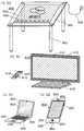
도 7a 내지 도 7d는 전자 기기를 도시한 도면.
도 8은 이온화 포텐셜을 도시한 도면.
도 9는 에너지 밴드도.
도 10a는 샘플 2의 TEM 사진도이고, 도 10b는 모식도.FIG. 1A is a top view of a semiconductor device showing an embodiment of the present invention, FIGS. 1B and 1C are sectional views, and FIG. 1D is an energy band diagram.
2A to 2D are process sectional views of a semiconductor device showing one embodiment of the present invention.
3A to 3C show another example of a cross-sectional view showing an embodiment of the present invention.
4A to 4C are top views for explaining one embodiment of the semiconductor device.
5A and 5B are cross-sectional views illustrating one embodiment of a semiconductor device.
6A is a circuit diagram for explaining one form of a semiconductor device, and FIG. 6B is a cross-sectional view.
7A to 7D are diagrams showing electronic devices.
8 shows the ionization potential.
9 is an energy band diagram.
10A is a TEM photograph of
본 발명의 실시형태에 대하여 도면을 사용하여 이하에서 자세히 설명한다. 다만, 본 발명은 이하의 설명에 한정되지 않고, 그 형태 및 자세한 사항을 다양하게 변경할 수 있다는 것은 당업자라면 용이하게 이해할 수 있다. 또한, 본 발명은 이하의 실시형태의 기재 내용에 한정하여 해석되는 것이 아니다.DESCRIPTION OF THE PREFERRED EMBODIMENTS Embodiments of the present invention will be described below in detail with reference to the drawings. However, it is to be understood that the present invention is not limited to the following description, and that various changes in form and details may be readily apparent to those skilled in the art. The present invention is not limited to the description of the following embodiments.
(실시형태 1)(Embodiment 1)
본 실시형태에서는 반도체 장치 및 반도체 장치의 제작 방법의 일 형태를 도 1a 내지 도 2d를 사용하여 설명한다. 본 실시형태에서는 반도체 장치의 일례로서 산화물 반도체 적층을 갖는 트랜지스터에 대하여 기재한다.In this embodiment mode, one embodiment of a semiconductor device and a method of manufacturing a semiconductor device will be described with reference to FIGS. 1A to 2D. In the present embodiment, a transistor having an oxide semiconductor stack as an example of a semiconductor device is described.
도 1a 내지 도 1c에 도시된 트랜지스터는 톱 게이트 구조를 갖는 트랜지스터의 일례다. 또한, 도 1a 내지 도 1c에서는 톱 게이트 구조의 트랜지스터의 예를 도시하였지만, 특별히 한정되지 않고, 예를 들어, 보텀 게이트 구조의 트랜지스터를 제작할 수도 있다. 또한, 듀얼 게이트 구조를 제작할 수도 있다. 듀얼 게이트 구조는 산화물 반도체 적층 상하에 게이트 전극을 형성함으로써 제작할 수 있다. 도 1a는 상면도이고, 도 1a의 쇄선 XY로 절단한 단면이 도 1b에 상당하고, 도 1a의 쇄선 VW로 절단한 단면이 도 1c에 상당한다. 도 1b 및 도 1c는 산화물 반도체층의 계면을 실선을 사용하여 모식적으로 도시한 것이다. 재료, 성막 조건, 가열 처리에 따라서는 산화물 반도체층들의 계면이 불명확하게 되는 경우도 있다. 불명확하게 되는 경우에는, 서로 다른 복수의 산화물 반도체층의 혼합 영역 또는 혼합층이라고 부를 수 있는 개소가 형성될 수도 있다.The transistor shown in Figs. 1A to 1C is an example of a transistor having a top gate structure. 1A to 1C show an example of a top-gate structure transistor, it is not particularly limited, and for example, a bottom-gate structure transistor can also be fabricated. A dual gate structure may also be fabricated. The dual gate structure can be fabricated by forming gate electrodes above and below the oxide semiconductor stack. 1A is a top view, and FIG. 1A shows a section taken along a chain line XY and FIG. 1C shows a section taken along a chain line VW. 1B and 1C schematically show the interface of the oxide semiconductor layer using a solid line. Depending on the material, the deposition condition, and the heat treatment, the interface between the oxide semiconductor layers may become unclear. When it becomes unclear, a portion that may be referred to as a mixed region or a mixed layer of a plurality of different oxide semiconductor layers may be formed.
채널 길이 방향의 단면도인 도 1b에 도시된 바와 같이, 트랜지스터는 산화물 절연막(436)이 형성된 절연 표면을 갖는 기판(400) 위에 제 1 산화물 반도체층, 제 2 산화물 반도체층, 및 제 3 산화물 반도체층을 갖고, 소스 전극층(405a), 드레인 전극층(405b), 게이트 절연막(402), 게이트 전극층(401)을 갖는다. 제 1 산화물 반도체층은 산화물 절연막(436) 위에 접촉하여 형성되고, 제 2 산화물 반도체층은 제 1 산화물 반도체층 위에 형성되어 있다. 또한, 제 1 산화물 반도체층의 측면 및 제 2 산화물 반도체층의 측면을 덮어 제 3 산화물 반도체층을 갖는다. 또한, 제 3 산화물 반도체층의 주연부는 산화물 절연막(436)과 접촉된다.1B, which is a sectional view in the channel length direction, the transistor includes a first oxide semiconductor layer, a second oxide semiconductor layer, and a third oxide semiconductor layer (not shown) on a
또한, 제 3 산화물 반도체층의 에너지 갭은 제 1 산화물 반도체층의 에너지 갭과 거의 같고, 제 2 산화물 반도체층의 에너지 갭보다 크다.The energy gap of the third oxide semiconductor layer is substantially equal to the energy gap of the first oxide semiconductor layer and larger than the energy gap of the second oxide semiconductor layer.
게이트 절연막(402)을 개재하여 게이트 전극층(401)과 중첩된 채널 형성 영역은 3층으로 형성되고, 제 1 채널 형성 영역(121c), 제 2 채널 형성 영역(122c), 및 제 3 채널 형성 영역(123c)이 적층되어 있다.The channel forming region overlapped with the
또한, 채널 길이 방향으로 제 1 채널 형성 영역(121c)을 끼워 제 1 저저항 영역(121a) 및 제 1 저저항 영역(121b)을 갖는다. 또한, 채널 길이 방향으로 제 2 채널 형성 영역(122c)을 끼워 제 2 저저항 영역(122a) 및 제 2 저저항 영역(122b)을 갖는다. 또한, 채널 길이 방향으로 제 3 채널 형성 영역(123c)을 끼워 제 3 저저항 영역(123a) 및 제 3 저저항 영역(123b)을 갖는다.Also, the first low-
또한, 소스 전극층(405a) 및 드레인 전극층(405b)이 중첩된 제 1 영역(121d), 제 1 영역(121e), 제 2 영역(122d), 제 2 영역(122e), 제 3 영역(123d), 및 제 3 영역(123e)을 갖는다.The
도 1c는 채널 폭 방향의 단면도이고, 도 1b와 마찬가지로 제 2 산화물 반도체층의 단부, 즉, 제 2 영역(122d) 및 제 2 영역(122e)의 측면이 제 3 산화물 반도체층의 단부, 즉, 제 3 영역(123d) 및 제 3 영역(123e)으로 덮이면서 소스 전극층(405a) 및 드레인 전극층(405b)과 접촉되지 않은 구조로 한다. 이러한 구조로 함으로써, 트랜지스터의 소스 전극층(405a) 및 드레인 전극층(405b)의 누설 전류(기생 채널)의 발생을 저감시킨다.1C is a cross-sectional view in the channel width direction. As in FIG. 1B, the end portions of the second oxide semiconductor layer, that is, the side surfaces of the
또한, 도 1d는 도 1b에서의 막 두께 방향(D-D' 사이)의 에너지 밴드도를 도시한 것이다. 본 실시형태에서는 도 1d에 도시된 에너지 밴드도를 얻을 수 있도록 제 1 산화물 반도체층, 제 2 산화물 반도체층, 및 제 3 산화물 반도체층의 재료를 선택한다. 다만, 매립 채널이 형성되면 누설 전류를 저감시키는 데 있어서 충분한 효과를 얻을 수 있기 때문에, 도 1d에 도시된 바와 같이 전도대와 가전자대의 양쪽 모두에 오목부를 갖는 에너지 밴드도에 반드시 한정하지 않아도 좋고, 예를 들어, 전도대에만 오목부를 갖는 에너지 밴드도를 얻을 수 있는 구성으로 하여도 좋다.FIG. 1D shows an energy band diagram in the film thickness direction (between D-D ') in FIG. 1B. In this embodiment, the materials of the first oxide semiconductor layer, the second oxide semiconductor layer, and the third oxide semiconductor layer are selected so as to obtain the energy band diagram shown in FIG. 1D. However, since a sufficient effect can be obtained in reducing the leakage current when the buried channel is formed, the energy band diagram having concave portions in both the conduction band and the valence band as shown in Fig. 1 (D) For example, the energy band diagram having concave portions only in the conduction band may be obtained.
도 2a 내지 도 2d에 트랜지스터의 제작 방법의 일례를 도시하였다.2A to 2D show an example of a method of manufacturing a transistor.
우선, 절연 표면을 갖는 기판(400) 위에 산화물 절연막(436), 제 1 산화물 반도체층(101), 및 제 2 산화물 반도체층(102)을 형성한다.First, an
절연 표면을 갖는 기판(400)에 사용할 수 있는 기판에 큰 제한은 없지만, 적어도 이후의 가열 처리에 견딜 수 있을 정도의 내열성을 가져야 한다. 예를 들어, 바륨보로실리케이트 유리나 알루미노보로실리케이트 유리 등의 유리 기판, 세라믹 기판, 석영 기판, 사파이어 기판 등을 사용할 수 있다. 또한, 실리콘이나 탄화실리콘 등을 함유한 단결정 반도체 기판, 실리콘이나 탄화실리콘 등을 함유한 다결정 반도체 기판, 실리콘 게르마늄 등을 함유한 화합물 반도체 기판, SOI 기판 등을 적용할 수도 있고, 이들의 기판 위에 반도체 소자가 설치된 것을 기판(400)으로서 사용하여도 좋다.There is no particular limitation on the substrate that can be used for the
또한, 기판(400)으로서 가요성 기판을 사용하여 반도체 장치를 제작하여도 좋다. 가요성을 갖는 반도체 장치를 제작하는 경우에는, 가요성 기판 위에 산화물 반도체 적층을 포함한 트랜지스터를 직접 제작하여도 좋고, 다른 제작 기판에 산화물 반도체 적층을 포함한 트랜지스터를 제작한 후 박리하고 가요성 기판에 전치하여도 좋다. 또한, 제작 기판으로부터 박리하고 가요성 기판에 전치하기 위하여 제작 기판과 산화물 반도체 적층을 포함한 트랜지스터 사이에 박리층을 형성하면 좋다.Further, a semiconductor device may be manufactured using the flexible substrate as the
산화물 절연막(436)은 플라즈마 CVD법 또는 스퍼터링법 등에 의하여 산화실리콘, 산화질화실리콘, 산화알루미늄, 산화질화알루미늄, 산화하프늄, 산화갈륨, 질화산화실리콘, 질화산화알루미늄, 또는 이들의 혼합 재료를 사용하여 형성할 수 있다. 산화물 절연막(436)은 단층 구조 및 적층 구조 중 어느 쪽이라도 좋다. 본 실시형태에서는 산화물 절연막(436)으로서 스퍼터링법을 사용하여 형성하는 산화실리콘막을 사용한다.The
산화물 절연막(436)은 산화물 반도체 적층의 가장 아래에 위치하는 층 및 가장 위에 위치하는 층과 접촉되기 때문에 막 내(벌크 내)에 적어도 화학량론비를 초과하는 양의 산소가 존재하는 것이 바람직하다. 예를 들어, 산화물 절연막(436)으로서 산화실리콘막을 사용하는 경우에는, SiO2+α(다만, α>0)로 한다. 이와 같은 산화물 절연막(436)을 사용함으로써, 위 쪽에 형성된 산화물 반도체 적층에 산소를 공급할 수 있어 특성을 양호하게 할 수 있다. 산화물 반도체 적층에 산소를 공급함으로써, 막 내의 산소 결손을 보전할 수 있다.Since the
산화물 절연막(436) 위의 산화물 반도체 적층의 형성 공정에서 제 1 산화물 반도체층(101) 및 제 2 산화물 반도체층(102)에 수소 또는 물이 가능한 한 함유되지 않도록 하기 위하여 제 1 산화물 반도체층(101) 및 제 2 산화물 반도체층(102)을 형성하기 전의 처리로서 스퍼터링 장치의 예비 가열실에서 산화물 절연막(436)이 형성된 기판을 예비 가열함으로써 기판 및 산화물 절연막(436)에 흡착된 수소, 수분 등의 불순물을 탈리시켜 배기하는 것이 바람직하다. 또한, 예비 가열실에 설치된 배기 수단은 크라이오 펌프가 바람직하다.In order to prevent hydrogen or water from being contained in the first
산화물 반도체 적층에 사용하는 산화물 반도체는 적어도 인듐(In) 또는 아연(Zn)을 함유한 것이 바람직하다. In 및 Zn의 양쪽 모두를 함유한 것이 특히 바람직하다. 또한, In과 Zn에 추가하여 상기 산화물을 사용한 트랜지스터의 전기 특성의 편차를 저감시키기 위한 스테빌라이저로서 갈륨(Ga)을 함유한 것이 바람직하다. 또한, 스테빌라이저로서 주석(Sn)을 함유한 것이 바람직하다. 또한, 스테빌라이저로서 하프늄(Hf)을 함유한 것이 바람직하다. 또한, 스테빌라이저로서 알루미늄(Al)을 함유한 것이 바람직하다.The oxide semiconductor used for the stacking of the oxide semiconductor preferably contains at least indium (In) or zinc (Zn). It is particularly preferable that both of In and Zn are contained. In addition to In and Zn, it is preferable that gallium (Ga) is contained as a stabilizer for reducing variations in electric characteristics of the transistor using the oxide. Further, it is preferable that tin (Sn) is contained as a stabilizer. Further, it is preferable that hafnium (Hf) is contained as a stabilizer. Further, it is preferable that aluminum (Al) is contained as a stabilizer.
또한, 다른 스테빌라이저로서 란타노이드인 란탄(La), 세륨(Ce), 프라세오디뮴(Pr), 네오디뮴(Nd), 사마륨(Sm), 유로퓸(Eu), 가돌리늄(Gd), 테르븀(Tb), 디스프로슘(Dy), 홀뮴(Ho), 에르븀(Er), 툴륨(Tm), 이테르븀(Yb), 루테튬(Lu) 중 어느 하나 또는 복수 종류를 가져도 좋다.Other stabilizers include lanthanides La, Ce, Pr, Ne, Sm, Eu, Gd, Terbium, Dibromide, (Dy), holmium (Ho), erbium (Er), thulium (Tm), ytterbium (Yb), and lutetium (Lu).
예를 들어, 산화물 반도체로서, 산화인듐, 산화주석, 산화아연, 2원계 금속의 산화물인 In-Zn계 산화물, Sn-Zn계 산화물, Al-Zn계 산화물, Zn-Mg계 산화물, Sn-Mg계 산화물, In-Mg계 산화물, In-Ga계 산화물, 3원계 금속의 산화물인 In-Ga-Zn계 산화물(IGZO라고도 표기함), In-Al-Zn계 산화물, In-Sn-Zn계 산화물, Sn-Ga-Zn계 산화물, Al-Ga-Zn계 산화물, Sn-Al-Zn계 산화물, In-Hf-Zn계 산화물, In-La-Zn계 산화물, In-Ce-Zn계 산화물, In-Pr-Zn계 산화물, In-Nd-Zn계 산화물, In-Sm-Zn계 산화물, In-Eu-Zn계 산화물, In-Gd-Zn계 산화물, In-Tb-Zn계 산화물, In-Dy-Zn계 산화물, In-Ho-Zn계 산화물, In-Er-Zn계 산화물, In-Tm-Zn계 산화물, In-Yb-Zn계 산화물, In-Lu-Zn계 산화물, 4원계 금속의 산화물인 In-Sn-Ga-Zn계 산화물, In-Hf-Ga-Zn계 산화물, In-Al-Ga-Zn계 산화물, In-Sn-Al-Zn계 산화물, In-Sn-Hf-Zn계 산화물, In-Hf-Al-Zn계 산화물을 사용할 수 있다.Examples of the oxide semiconductor include indium oxide, tin oxide, zinc oxide, an In-Zn-based oxide, an Sn-Zn-based oxide, an Al-Zn-based oxide, a Zn-Mg- In-Zn-Zn-based oxide, In-Al-Zn-based oxide, In-Sn-Zn-based oxide (also referred to as IGZO) which is an oxide of a ternary metal, Zn-based oxide, In-Ce-Zn-based oxide, Sn-Al-Zn-based oxide, In-Hf- Zn-based oxide, In-Tb-Zn-based oxide, In-Sm-Zn-based oxide, In- In-Zn-based oxide, In-Er-Zn-based oxide, In-Tm-Zn based oxide, In-Yb-Zn based oxide, In-Lu-Zn based oxide, Zn-based oxide, In-Sn-Ga-Zn-based oxide, In-Hf-Ga-Zn-based oxide, In-Al- , In-Hf-Al-Zn-based oxides can be used All.
산화물 반도체는 단결정 및 비단결정 중 어느 쪽이라도 좋다. 후자의 경우에는, 비정질 및 다결정 중 어느 쪽이라도 좋다. 또한, 비정질 내에 결정성을 갖는 부분을 포함하는 구조라도 좋고, 비정질이 아니라도 좋다. 또한, 같은 재료를 사용한 경우라도 단결정의 에너지 갭과 비단결정의 에너지 갭이 다를 수 있기 때문에 결정 상태를 적절히 선택하는 것이 중요하다. 도 1d에 도시된 에너지 밴드도를 얻을 수 있도록 제 1 산화물 반도체층(101) 및 제 2 산화물 반도체층(102)의 재료를 선택한다.The oxide semiconductor may be either a single crystal or a non-single crystal. In the latter case, either amorphous or polycrystal may be used. Further, the structure may include a portion having crystallinity in the amorphous state, and may not be amorphous. Even when the same material is used, it is important to select the crystal state appropriately because the energy gap of the single crystal and the energy gap of the non-single crystal may be different from each other. The materials of the first
또한, 산화물 반도체 적층으로서 결정을 포함하고 결정성을 갖는 산화물 반도체막(결정성 산화물 반도체막)을 사용할 수 있다. 결정성 산화물 반도체막에서의 결정 상태는 결정 축의 방향이 무질서한 상태라도 좋고, 일정한 배향성을 갖는 상태라도 좋다.Further, an oxide semiconductor film (crystalline oxide semiconductor film) containing crystals and having crystallinity can be used as the oxide semiconductor laminate. The crystal state in the crystalline oxide semiconductor film may be a state in which the direction of the crystal axis is disordered or a state in which the crystal axis has a constant orientation.
예를 들어, 결정성 산화물 반도체막으로서 표면에 대략 수직인 c축을 갖는 결정을 포함한 산화물 반도체막을 사용할 수 있다.For example, an oxide semiconductor film containing a crystal having a c-axis substantially perpendicular to the surface can be used as the crystalline oxide semiconductor film.
표면에 대략 수직의 c축을 갖는 결정을 포함한 산화물 반도체막은 단결정 구조가 아니고 비정질 구조도 아닌 구조이며, c축 배향을 갖는 결정성 산화물 반도체(C Axis Aligned Crystalline Oxide Semiconductor; CAAC-OS라고도 함)다.The oxide semiconductor film containing crystals having a c-axis substantially perpendicular to the surface is not a single crystal structure nor an amorphous structure and is a C-axis Aligned Crystalline Oxide Semiconductor (CAAC-OS).
CAAC-OS란 c축 배향하고 또 ab면, 표면, 또는 계면의 방향에서 관찰하여 삼각 형상 또는 육각 형상의 원자 배열을 갖고, c축에서 금속 원자가 층 형상으로 배열되거나 또는 금속 원자와 산소 원자가 층 형상으로 배열되어 있고, ab면(또는 표면 또는 계면)에서 a축 또는 b축의 방향이 다른(c축을 중심으로 회전한) 결정을 포함한 산화물 반도체다.CAAC-OS refers to c-axis oriented, and has an atomic arrangement of triangular or hexagonal shape observed from the direction of ab plane, surface, or interface, in which metal atoms are arranged in layers on the c axis, And an oxide semiconductor containing crystals whose axes or axes are different in direction (rotated about the c axis) on the ab plane (or surface or interface).
넓은 의미로는 CAAC-OS란 비단결정이며 그 ab면에 수직인 방향에서 관찰하여 삼각형 또는 육각형, 또는 정삼각형 또는 정육각형의 원자 배열을 갖고 또 c축 방향에 수직인 방향에서 관찰하여 금속 원자가 층 형상으로 배열되거나 또는 금속 원자와 산소 원자가 층 형상으로 배열된 상을 포함한 재료를 가리킨다.In a broad sense, CAAC-OS is non-deterministic. It is observed in a direction perpendicular to the ab plane, and is observed in a triangular or hexagonal shape, or in a direction perpendicular to the c-axis direction, Or a material containing an image in which metal atoms and oxygen atoms are arranged in layers.
CAAC-OS는 단결정이 아니지만, 비정질만으로 형성되어 있는 것도 아니다. 또한, CAAC-OS는 결정화된 부분(결정 부분)을 포함하지만, 하나의 결정 부분과 다른 결정 부분의 경계를 명확히 판별할 수 없는 경우도 있다.CAAC-OS is not a single crystal, but it is not formed by amorphous. In addition, the CAAC-OS includes a crystallized part (crystal part), but there is also a case where the boundary between one crystal part and another crystal part can not be clearly discriminated.
CAAC-OS를 구성하는 산소의 일부는 질소로 치환되어도 좋다. 또한, CAAC-OS를 구성하는 개개의 결정 부분의 c축은 일정한 방향(예를 들어, CAAC-OS가 형성되는 기판면, CAAC-OS의 표면, 막면, 계면 등에 수직인 방향)으로 일치되어 있어도 좋다. 또는, CAAC-OS를 구성하는 개개의 결정 부분의 ab면의 법선은 일정한 방향(예를 들어, 기판면, 표면, 막면, 계면 등에 수직인 방향)을 향하여도 좋다.Some of the oxygen constituting the CAAC-OS may be substituted with nitrogen. The c-axes of individual crystal portions constituting the CAAC-OS may coincide with each other in a certain direction (for example, the direction perpendicular to the surface of the CAAC-OS, the surface of the CAAC-OS, the interface, etc.) . Or, the normal line of the ab plane of each crystal part constituting the CAAC-OS may be directed to a certain direction (for example, a direction perpendicular to the substrate surface, the surface, the film surface, the interface or the like).
상기 결정성 산화물 반도체막으로 함으로써 가시광이나 자외광의 조사로 인한 트랜지스터의 전기적 특성 변화를 더 억제하여 신뢰성이 높은 반도체 장치로 할 수 있다.By using the crystalline oxide semiconductor film, it is possible to further suppress the change in the electrical characteristics of the transistor due to the irradiation of visible light or ultraviolet light, thereby realizing a highly reliable semiconductor device.
제 1 산화물 반도체층(101) 및 제 2 산화물 반도체층(102)은 막 두께가 5nm 이상 100nm 이하(바람직하게는 5nm 이상 30nm 이하)이고, 스퍼터링법, MBE(Molecular Beam Epitaxy)법, CVD법, 펄스 레이저 퇴적법, ALD(Atomic Layer Deposition)법 등을 적절히 사용하여 형성할 수 있다. 또한, 제 1 산화물 반도체층(101) 및 제 2 산화물 반도체층(102)은 스퍼터링 타깃 표면에 대략 수직으로 복수의 기판 표면이 고정된 상태에서 성막하는 스퍼터링 장치, 소위 CP 스퍼터링 장치(Columnar Plasma Sputtering system)를 사용하여 형성하여도 좋다.The first
또한, 제 1 산화물 반도체층(101) 및 제 2 산화물 반도체층(102)은 형성시에 산소가 많이 함유된 조건(예를 들어, 산소 100%의 분위기하에서 스퍼터링법을 사용하여 형성하는 등)으로 형성하여 산소가 많이 함유된(바람직하게는 산화물 반도체가 결정 상태에서의 화학량론적 조성비보다 산소의 함유량이 과잉인 영역이 포함되는) 막으로 하는 것이 바람직하다.The first
또한, 본 실시형태에서 제 1 산화물 반도체층(101)을 스퍼터링법으로 제작하기 위한 타깃으로서는, 예를 들어, 조성비가 In2O3:Ga2O3:ZnO=1:1:2[mol비]인 산화물 타깃을 사용하여 In-Ga-Zn계 산화물막을 형성한다. 또한, 이 타깃의 재료 및 조성에 한정되지 않고, 예를 들어, In2O3:Ga2O3:ZnO=1:1:1[mol비]의 금속 산화물 타깃을 사용하여도 좋다.In this embodiment, a target for forming the first
제 1 산화물 반도체층(101) 및 제 2 산화물 반도체층(102)을 형성할 때 사용하는 스퍼터링 가스로서 수소, 물, 수산기, 또는 수소화물 등의 불순물이 제거된 고순도 가스를 사용하는 것이 바람직하다.It is preferable to use a high purity gas from which impurities such as hydrogen, water, hydroxyl, or hydride have been removed as a sputtering gas used for forming the first
또한, 산화물 절연막(436)과 산화물 반도체 적층을 대기에 노출시키지 않고 연속적으로 형성하는 것이 바람직하다. 산화물 절연막(436)과 산화물 반도체 적층을 대기에 노출시키지 않고 연속적으로 형성하면, 산화물 절연막(436) 표면에 수소나 수분 등의 불순물이 흡착되는 것을 방지할 수 있다.Further, it is preferable to continuously form the
본 실시형태에서는 도 2a에 도시된 바와 같이, 성막된 산화물 반도체 적층을 제 1 포토리소그래피 공정에 의하여 섬 형상의 제 1 산화물 반도체층(101) 및 섬 형상의 제 2 산화물 반도체층(102)으로 가공한다. 또한, 섬 형상의 제 1 산화물 반도체층(101) 및 섬 형상의 제 2 산화물 반도체층(102)을 형성하기 위한 레지스트 마스크를 잉크젯법으로 형성하여도 좋다. 레지스트 마스크를 잉크젯법으로 형성하면 포토마스크를 사용하지 않기 때문에, 제조 비용을 저감시킬 수 있다.In this embodiment, as shown in FIG. 2A, the deposited oxide semiconductor layer is processed into a first island-shaped
또한, 산화물 반도체 적층의 에칭에는 드라이 에칭 및 웨트 에칭 중 어느 쪽을 사용하여도 좋고, 드라이 에칭 및 웨트 에칭의 양쪽 모두를 사용하여도 좋다. 예를 들어, 산화물 반도체막의 웨트 에칭에 사용하는 에칭액으로서는, 인산과 초산과 질산을 혼합한 용액 등을 사용할 수 있다. 또한, ITO07N(KANTO CHEMICAL CO.,INC 제조)을 사용하여도 좋다.Either dry etching or wet etching may be used for etching the oxide semiconductor laminate, or both dry etching and wet etching may be used. For example, a solution obtained by mixing phosphoric acid, acetic acid, and nitric acid, or the like can be used as the etching solution used for wet etching of the oxide semiconductor film. ITO07N (manufactured by KANTO CHEMICAL CO., INC.) May also be used.
다음에, 섬 형상의 제 1 산화물 반도체층(101) 및 섬 형상의 제 2 산화물 반도체층(102)을 덮는 제 3 산화물 반도체층(103)을 형성한다. 제 3 산화물 반도체층(103)은 제 1 산화물 반도체층(101)과 같은 타깃을 사용하여 형성한다. 제 3 산화물 반도체층(103)의 성막 조건은 제 1 산화물 반도체층(101)과 같기 때문에 여기서는 설명을 생략한다. 또한, 제 2 포토리소그래피 공정에 의하여 제 2 산화물 반도체층(102)과 중첩되고 또 제 2 산화물 반도체층(102)의 평면 면적보다 넓은 상면 면적을 갖는 제 3 산화물 반도체층(103)을 형성한다.Next, a third
다음에, 과잉 수소(물이나 수산기를 포함함)를 제거(탈수화 또는 탈수소화)하기 위하여 제 1 산화물 반도체층(101), 제 2 산화물 반도체층(102), 및 제 3 산화물 반도체층(103)에 가열 처리를 행하여도 좋다. 가열 처리의 온도는 300℃ 이상 700℃ 이하 또는 기판의 변형점 미만으로 한다. 가열 처리는 감압하 또는 질소 분위기하 등에서 행할 수 있다. 예를 들어, 가열 처리 장치 중 하나인 전기로에 기판을 놓고, 제 1 산화물 반도체층(101), 제 2 산화물 반도체층(102), 및 제 3 산화물 반도체층(103)에 질소 분위기하에서 450℃로 1시간의 가열 처리를 행한다.Next, a first
또한, 가열 처리 장치는 전기로에 한정되지 않고, 저항 발열체 등의 발열체로부터의 열 전도 또는 열 복사에 의하여 피처리물을 가열하는 장치를 사용하여도 좋다. 예를 들어, GRTA(Gas Rapid Thermal Anneal) 장치, LRTA(Lamp Rapid Thermal Anneal) 장치 등의 RTA(Rapid Thermal Anneal) 장치를 사용할 수 있다. LRTA 장치는 할로겐 램프, 메탈 할라이드 램프, 크세논 아크 램프, 카본 아크 램프, 고압 나트륨 램프, 고압 수은 램프 등의 램프로부터 방사되는 빛(전자기파)의 복사에 의하여 피처리물을 가열하는 장치다. GRTA 장치는 고온 가스를 사용하여 가열 처리를 행하는 장치다. 고온 가스로서는 아르곤 등의 희가스, 또는 질소와 같은 가열 처리에 의하여 피처리물과 반응하지 않는 불활성 기체가 사용된다.Further, the heat treatment apparatus is not limited to an electric furnace, and an apparatus for heating the article to be treated by heat conduction or heat radiation from a heating element such as a resistance heating element may be used. For example, an RTA (Rapid Thermal Anneal) device such as a gas rapid thermal annealing (GRTA) device or a lamp rapid thermal annealing (LRTA) device can be used. The LRTA device is a device for heating a material to be irradiated by radiation (electromagnetic wave) radiated from a lamp such as a halogen lamp, a metal halide lamp, a xenon arc lamp, a carbon arc lamp, a high pressure sodium lamp, and a high pressure mercury lamp. The GRTA apparatus is a device for performing heat treatment using a high temperature gas. As the high-temperature gas, a rare gas such as argon or an inert gas which does not react with the object to be treated by a heat treatment such as nitrogen is used.
예를 들어, 가열 처리로서 650℃ 내지 700℃의 고온으로 가열한 불활성 가스 내에 기판을 놓고 몇 분 동안 가열한 후 기판을 불활성 가스 내로부터 꺼내는 GRTA를 행하여도 좋다.For example, as the heat treatment, GRTA may be performed in which the substrate is placed in an inert gas heated to a high temperature of 650 ° C to 700 ° C, heated for several minutes, and then the substrate is taken out of the inert gas.
또한, 가열 처리에서는 질소, 또는 헬륨, 네온, 아르곤 등의 희가스에 물, 수소 등이 함유되지 않는 것이 바람직하다. 또는, 가열 처리 장치에 도입하는 질소, 또는 헬륨, 네온, 아르곤 등의 희가스의 순도를 6N(99.9999%) 이상, 바람직하게는 7N(99.99999%) 이상(즉, 불순물 농도를 1ppm 이하, 바람직하게는 0.1ppm 이하)으로 하는 것이 바람직하다.In the heat treatment, it is preferable that the rare gas such as nitrogen or helium, neon or argon does not contain water, hydrogen or the like. Or the purity of the rare gas such as nitrogen, helium, neon or argon introduced into the heat treatment apparatus to 6N (99.9999%) or more, preferably 7N (99.99999%) or more (that is, the impurity concentration is 1 ppm or less, 0.1 ppm or less).
또한, 제 1 산화물 반도체층(101), 제 2 산화물 반도체층(102), 및 제 3 산화물 반도체층(103)을 가열 처리한 후, 가열 온도를 유지한 채 또는 그 가열 온도에서 서서히 냉각하면서 동일한 노에 고순도 산소 가스, 고순도 일산화이질소 가스, 또는 초건조 공기(CRDS(캐비티 링다운 레이저 분광법) 방식의 노점 측정기를 사용하여 측정한 경우의 수분량이 20ppm(노점 환산으로 -55℃) 이하, 바람직하게는 1ppm 이하, 더 바람직하게는 10ppb 이하의 공기)를 도입하여도 좋다. 산소 가스 또는 일산화이질소 가스에 물, 수소 등이 함유되지 않는 것이 바람직하다. 또는, 가열 처리 장치에 도입하는 산소 가스 또는 일산화이질소 가스의 순도를 6N 이상, 바람직하게는 7N 이상(즉, 산소 가스 또는 일산화이질소 가스 내의 불순물 농도를 1ppm 이하, 바람직하게는 0.1ppm 이하)으로 하는 것이 바람직하다. 탈수화 또는 탈수소화 처리를 사용한 불순물의 배제 공정에 의하여 감소된 산화물 반도체를 구성하는 주성분 재료인 산소를 산소 가스 또는 일산화이질소 가스의 작용에 의하여 공급함으로써, 제 1 산화물 반도체층(101), 제 2 산화물 반도체층(102), 및 제 3 산화물 반도체층(103)을 고순도화 및 전기적으로 i형(진성)화할 수 있다.After the first
다음에, 제 3 산화물 반도체층(103) 위에 소스 전극층 및 드레인 전극층(이것과 동일한 층으로 형성되는 배선을 포함함)이 되는 도전막을 형성한다. 상기 도전막으로서 이후에 행해지는 가열 처리에 견딜 수 있는 재료를 사용한다. 소스 전극층 및 드레인 전극층에 사용하는 도전막으로서, 예를 들어, Al, Cr, Cu, Ta, Ti, Mo, 및 W 중에서 선택된 원소를 함유한 금속막, 또는 상술한 원소를 성분으로 하는 금속 질화물막(질화티타늄막, 질화몰리브덴막, 질화텅스텐막) 등을 사용할 수 있다. 또한, Al, Cu 등의 금속막의 아래측 또는 위측의 한쪽 또는 양쪽 모두에 Ti, Mo, W 등의 고융점 금속막 또는 이들의 금속 질화물막(질화티타늄막, 질화몰리브덴막, 질화텅스텐막)을 적층시킨 구성으로 하여도 좋다. 또한, 소스 전극층 및 드레인 전극층에 사용하는 도전막으로서는 도전성 금속 산화물을 사용하여 형성하여도 좋다. 도전성 금속 산화물로서는 산화인듐(In2O3), 산화주석(SnO2), 산화아연(ZnO), 산화인듐-산화주석(In2O3-SnO2, ITO라고 약기함), 산화인듐-산화아연(In2O3-ZnO), 또는 이들 금속 산화물 재료에 산화실리콘을 함유시킨 것을 사용할 수 있다.Next, a conductive film to be a source electrode layer and a drain electrode layer (including wirings formed of the same layer as this) is formed on the third
제 3 포토리소그래피 공정에 의하여 도전막 위에 레지스트 마스크를 형성하고 선택적으로 에칭하여 소스 전극층(405a) 및 드레인 전극층(405b)을 형성한 후 레지스트 마스크를 제거한다. 도 2b는 이 단계에서의 단면을 도시한 것이다. 본 실시형태에서는 소스 전극층(405a) 및 드레인 전극층(405b)으로서 막 두께가 10nm인 텅스텐막을 형성한다. 이와 같이 소스 전극층(405a) 및 드레인 전극층(405b)의 두께가 얇으면, 위에 형성되는 게이트 절연막(402)의 피복성이 양호할 뿐만 아니라 소스 전극층(405a) 및 드레인 전극층(405b)을 통과하여 적어도 소스 전극층(405a) 및 드레인 전극층(405b) 아래의 적어도 제 3 산화물 반도체층(103)에 도펀트를 도입할 수 있다.A resist mask is formed on the conductive film by a third photolithography process and selectively etched to form a
다음에, 제 3 산화물 반도체층(103), 소스 전극층(405a), 및 드레인 전극층(405b)을 덮는 게이트 절연막(402)을 형성한다.Next, a
게이트 절연막(402)은 막 두께가 1nm 이상 20nm 이하이고, 스퍼터링법, MBE법, CVD법, 펄스 레이저 퇴적법, ALD법 등을 적절히 사용하여 형성할 수 있다. 또한, 게이트 절연막(402)은 스퍼터링 타깃 표면에 대략 수직으로 복수의 기판 표면이 세트된 상태로 성막하는 스퍼터링 장치, 소위 CP 스퍼터링 장치를 사용하여 형성하여도 좋다.The
게이트 절연막(402)은 산화실리콘막, 산화갈륨막, 산화알루미늄막, 질화실리콘막, 산화질화실리콘막, 산화질화알루미늄막, 또는 질화산화실리콘막을 재료로서 사용하여 형성할 수 있다.The
또한, 게이트 절연막(402)의 재료로서 산화하프늄, 산화이트륨, 하프늄실리케이트(HfSixOy(x>0, y>0)), 질소가 첨가된 하프늄실리케이트(HfSiOxNy(x>0, y>0)), 하프늄알루미네이트(HfAlxOy(x>0, y>0)), 산화란탄 등의 high-k 재료를 사용함으로써 게이트 누설 전류를 저감시킬 수 있다. 또한, 게이트 절연막(402)은 단층 구조와 적층 구조의 어느 쪽이라도 좋다.As the material of the
다음에, 도 2c에 도시된 바와 같이, 소스 전극층(405a), 드레인 전극층(405b)을 마스크로서 사용하여 적어도 제 3 산화물 반도체층(103)에 적어도 산소 라디칼, 산소 원자, 산소 이온 중 어느 것을 포함한 산소(431)를 도입한다. 도 2c에 도시된 바와 같이, 제 1 산소 과잉 영역(111), 제 2 산소 과잉 영역(112), 및 제 3 산소 과잉 영역(113)은 산화물 반도체층의 소스 전극층(405a) 및 드레인 전극층(405b)과 중첩된 영역보다 산소를 많이 함유한다. 산소의 도입 방법으로서는, 이온 주입법, 이온 도핑법, 플라즈마 이머전 이온 주입법, 플라즈마 처리 등을 사용할 수 있다.Next, as shown in Fig. 2C, at least the third
그리고, 플라즈마 CVD법 또는 스퍼터링법 등을 사용하여 게이트 전극층(401)을 게이트 절연막(402) 위에 형성한다. 게이트 전극층(401)의 재료로서는 몰리브덴, 티타늄, 탄탈, 텅스텐, 알루미늄, 구리, 크롬, 네오듐, 스칸듐 등의 금속 재료 또는 이들을 주성분으로 하는 합금 재료를 사용하여 형성할 수 있다. 또한, 게이트 전극층(401)으로서 인 등의 불순물 원소를 도핑한 다결정 실리콘막으로 대표되는 반도체막, 니켈실리사이드 등의 실리사이드막을 사용하여도 좋다. 게이트 전극층(401)은 단층 구조와 적층 구조의 어느 쪽이라도 좋다.Then, a
또한, 게이트 전극층(401)의 재료로서는 인듐주석 산화물, 산화텅스텐을 함유한 인듐 산화물, 산화텅스텐을 함유한 인듐아연 산화물, 산화티타늄을 함유한 인듐 산화물, 산화티타늄을 함유한 인듐주석 산화물, 인듐아연 산화물, 산화실리콘이 첨가된 인듐주석 산화물 등의 도전성 재료를 적용할 수도 있다. 또한, 상기 도전성 재료와 상기 금속 재료의 적층 구조로 할 수도 있다.The material of the
또한, 게이트 절연막(402)과 접촉하는 게이트 전극층(401)의 하나의 층으로서 질소를 함유한 금속 산화물, 구체적으로는 질소를 함유한 In-Ga-Zn-O막, 질소를 함유한 In-Sn-O막, 질소를 함유한 In-Ga-O막, 질소를 함유한 In-Zn-O막, 질소를 함유한 Sn-O막, 질소를 함유한 In-O막, 금속 질화막(InN, SnN 등)을 사용할 수 있다. 이들 막은 일함수가 5eV, 바람직하게는 5.5eV 이상이므로 게이트 전극층으로서 사용하면 트랜지스터의 전기 특성의 임계값 전압을 양으로 할 수 있어 소위 노멀리-오프의 스위칭 소자를 실현할 수 있다.In addition, as a layer of the
다음에, 도펀트(421)를 선택적으로 도입하는 공정을 행한다. 이 공정에서 게이트 전극층(401)을 마스크로서 사용하여 도펀트(421)를 게이트 절연막(402)을 통과시켜 산화물 반도체 적층에 도입함으로써, 제 1 저저항 영역(121a), 제 1 저저항 영역(121b), 제 2 저저항 영역(122a), 제 2 저저항 영역(122b), 제 3 저저항 영역(123a), 및 제 3 저저항 영역(123b)을 형성한다. 이 공정에서 채널 길이 방향으로 제 1 채널 형성 영역(121c)을 끼워 제 1 저저항 영역(121a) 및 제 1 저저항 영역(121b)이 자기 정합적으로 형성된다. 또한, 채널 길이 방향으로 제 2 채널 형성 영역(122c)을 끼워 제 2 저저항 영역(122a) 및 제 2 저저항 영역(122b)이 자기 정합적으로 형성된다. 또한, 채널 길이 방향으로 제 3 채널 형성 영역(123c)을 끼워 제 3 저저항 영역(123a) 및 제 3 저저항 영역(123b)이 자기 정합적으로 형성된다.Next, a step of selectively introducing the
또한, 이 공정에서 게이트 절연막(402), 소스 전극층(405a), 드레인 전극층(405b)을 통과하여 적어도 제 3 산화물 반도체층(103)에 도펀트(421)를 선택적으로 도입하여 제 1 영역(121d), 제 1 영역(121e), 제 2 영역(122d), 제 2 영역(122e), 제 3 영역(123d), 및 제 3 영역(123e)을 형성한다(도 2d 참조). 소스 전극층(405a) 및 드레인 전극층(405b) 아래의 산화물 반도체 적층에도 도펀트(421)를 도입함으로써 제 1 영역(121d), 제 1 영역(121e), 제 2 영역(122d), 제 2 영역(122e), 제 3 영역(123d), 및 제 3 영역(123e)의 저저항화를 도모할 수 있다.In this step, the
본 실시형태에서는 소스 전극층(405a) 및 드레인 전극층(405b)의 막 두께가 얇기 때문에 소스 전극층(405a) 및 드레인 전극층(405b) 아래의 산화물 반도체 적층에도 도펀트(421)가 도입된다. 소스 전극층(405a) 및 드레인 전극층(405b)의 막 두께나 도펀트(421)의 도입 조건에 따라서는 소스 전극층(405a) 및 드레인 전극층(405b) 아래의 산화물 반도체 적층에는 도펀트(421)가 도입되지 않는 구성으로 할 수도 있다.Since the thickness of the
도펀트(421)의 도입 공정은 가속 전압, 도즈량 등의 주입 조건 및 통과시키는 게이트 절연막(402)의 막 두께를 적절히 설정하여 제어하면 좋다. 예를 들어, 붕소를 사용하여 이온 주입법으로 붕소 이온을 주입하는 경우에는, 도즈량을 1×10¹³ions/cm2 이상 5×10¹⁶ions/cm2 이하로 하면 좋다.The
제 1 저저항 영역(121a), 제 1 저저항 영역(121b), 제 2 저저항 영역(122a), 제 2 저저항 영역(122b), 제 3 저저항 영역(123a), 및 제 3 저저항 영역(123b)에서의 도펀트(421)의 농도는 5×10¹⁸/cm3 이상 1×10²²/cm3 이하인 것이 바람직하다.The first
기판(400)을 가열하면서 도펀트(421)를 도입하여도 좋다.The
또한, 제 1 저저항 영역(121a), 제 1 저저항 영역(121b), 제 2 저저항 영역(122a), 제 2 저저항 영역(122b), 제 3 저저항 영역(123a), 및 제 3 저저항 영역(123b)에 도펀트(421)를 도입하는 처리는 복수 횟수 행하여도 좋고, 복수 종류의 도펀트를 사용하여도 좋다.The first
또한, 도펀트(421) 도입 처리 후, 가열 처리를 행하여도 좋다. 가열 조건으로는 300℃ 이상 700℃ 이하, 바람직하게는 300℃ 이상 450℃ 이하의 온도로 산소 분위기하에서 1시간 동안 행하는 것이 바람직하다. 또한, 질소 분위기하, 감압하, 대기(초건조 공기)하에서 가열 처리하여도 좋다.Further, after the
산화물 반도체 적층의 적어도 하나의 층을 결정성 산화물 반도체막으로 한 경우에는 도펀트(421)가 도입됨으로써 일부가 비정질화될 수 있다. 이러한 경우에는 도펀트(421) 도입 후에 가열 처리함으로써 산화물 반도체 적층의 결정성을 회복시킬 수 있다.In the case where at least one layer of the oxide semiconductor stacked layer is a crystalline oxide semiconductor film, a portion of the oxide semiconductor layer may be amorphized by introducing the
본 실시형태에서는 도펀트(421)로서 붕소를 사용하기 때문에 제 1 저저항 영역(121a), 제 1 저저항 영역(121b), 제 2 저저항 영역(122a), 제 2 저저항 영역(122b), 제 3 저저항 영역(123a) 및 제 3 저저항 영역(123b)에는 붕소가 함유된다.The first
상술한 공정을 거쳐 본 실시형태의 트랜지스터가 제작된다. 본 실시형태의 트랜지스터에서 고순도화되고 산소 결손이 보전된 산화물 반도체 적층은 수소, 물 등의 불순물이 충분히 제거되어 있고, 산화물 반도체 적층 내의 수소 농도는 5×10¹⁹/cm3 이하, 바람직하게는 5×10¹⁸/cm3 이하다. 또한, 산화물 반도체 적층 내의 수소 농도는 2차 이온 질량 분석법(SIMS: Secondary Ion Mass Spectrometry)으로 측정되는 것이다.The transistor of this embodiment is fabricated through the above-described processes. Impurities such as hydrogen and water are sufficiently removed in the oxide semiconductor laminate in which the transistor of the present embodiment is highly purified and the oxygen defect is preserved. The hydrogen concentration in the oxide semiconductor laminate is 5 x 10¹⁹ / cm3 or less, preferably 5 × 10¹⁸ / cm3 or less. Further, the hydrogen concentration in the oxide semiconductor laminate is measured by secondary ion mass spectrometry (SIMS).
그리고, 트랜지스터를 덮도록 절연막(407)을 형성한다(도 1b 및 도 1c 참조).Then, an insulating
절연막(407)은 산화실리콘막 외 대표적으로는 산화알루미늄막, 산화질화실리콘막, 산화질화알루미늄막, 또는 산화갈륨막 등의 무기 절연막을 사용할 수 있다. 예를 들어, 절연막(407)으로서 산화실리콘막과 산화알루미늄막의 적층을 사용할 수 있다.As the insulating
절연막(407)으로서 사용할 수 있는 산화알루미늄막은 수소, 수분 등의 불순물 및 산소의 양쪽 모두가 막을 통과하는 것을 차단하는 효과(블로킹 효과)가 높다.The aluminum oxide film that can be used as the insulating
또한, 절연막(407)으로서 평탄화 절연막을 사용하여도 좋다. 평탄화 절연막으로서는 폴리이미드 수지, 아크릴 수지, 벤조시클로부텐계 수지 등의 유기 재료를 사용할 수 있다. 또한, 상기 유기 재료 외에 저유전율 재료(low-k 재료) 등을 사용할 수 있다. 또한, 이들 재료로 형성되는 복수의 절연막을 적층시킴으로써 평탄화 절연막을 형성하여도 좋다.Note that a planarization insulating film may be used as the insulating
다음에, 절연막(407)에 소스 전극층(405a) 및 드레인 전극층(405b)에 도달하는 개구를 형성하고, 개구에 소스 전극층(405a) 및 드레인 전극층(405b)과 전기적으로 접속된 배선층을 형성한다. 이 배선층을 사용하여 다른 트랜지스터와 접속시켜 다양한 회로를 구성할 수 있다.Next, an opening reaching the
상술한 바와 같이 하여 얻어진 전기 특성이 높은 트랜지스터를 사용함으로써 성능이 높고 신뢰성이 높은 반도체 장치를 제공할 수 있다.By using a transistor having a high electrical characteristic obtained as described above, a semiconductor device with high performance and high reliability can be provided.
또한, 본 실시형태를 사용하여 채널 형성 영역에 산화물 반도체 적층을 사용한 트랜지스터는 오프 상태에서의 전류값(오프 전류값)을 채널 폭 1μm당 실온으로 100zA/μm(1zA(젭토암페어)는 1×10-21A) 이하, 바람직하게는 10zA/μm 이하, 더 바람직하게는 1zA/μm 이하, 더 나아가서는 100yA/μm 이하 레벨까지 낮게 할 수도 있다.In the transistor using the oxide semiconductor lamination layer in the channel forming region, the current value (off current value) in the off state is set to 100 zA / m (1 zA (ampere ampere)-21 A), preferably not more than 10 zA / μm, more preferably not more than 1 zA / μm, furthermore not more than 100 yA / μm.
(실시형태 2)(Embodiment 2)
본 실시형태에서는 실시형태 1의 공정을 부분적으로 변경하여 얻어지는 트랜지스터의 일례를 도 3a 내지 도 3c를 사용하여 설명한다. 실시형태 1과 일부만 다르기 때문에 간략화를 위하여 동일 부호를 사용하여 설명하고, 여기서는, 동일 부분의 상세한 설명은 생략하는 것으로 한다.In this embodiment, an example of a transistor obtained by partially changing the process of the first embodiment will be described with reference to Figs. 3A to 3C. Since they are only partially different from
도 3a는 산화물 반도체 적층의 에칭을 행할 때 산화물 반도체 적층과 중첩되지 않은 산화물 절연막(436)의 영역을 에칭하여 일부를 얇게 한 구성이다. 산화물 절연막의 일부까지 에칭함으로써 제 1 산화물 반도체층의 잔사 등의 에칭 잔사를 제거하고, 누설 전류의 발생을 저감시킬 수 있다. 또한, 도 3a의 트랜지스터는 산소를 도입할 때 또는 도펀트를 도입할 때의 조건을 바꿈으로써 제 1 산화물 반도체층(101)에 도펀트가 거의 도입되지 않는 구성이다. 이러한 구성으로 함으로써 산소를 도입할 때 또는 도펀트를 도입할 때의 대미지를 억제할 수 있다. 또한, 산소를 도입할 때 또는 도펀트를 도입할 때의 조건을 바꿈으로써 제 2 산화물 반도체층에도 도펀트가 거의 도입되지 않는 구성으로 하여도 좋다.3A shows a structure in which a portion of the
또한, 도 3b는 제 1 산화물 반도체층의 에칭에 사용한 제 1 마스크와, 제 2 산화물 반도체층의 에칭에 사용한 제 2 마스크와, 제 3 산화물 반도체층의 에칭에 사용한 제 3 마스크를 사용한 3번의 포토리소그래피 공정에 의하여 제 1 산화물 반도체층의 측면이 제 2 산화물 반도체층의 측면보다 돌출된 구조로 하고 제 3 산화물 반도체층이 제 1 산화물 반도체층의 상면의 일부와 접촉된 구성으로 한 예다. 제 3 산화물 반도체층의 단부에 상당하는 제 3 영역(123d) 및 제 3 영역(123e)은 제 1 산화물 반도체층의 단부에 상당하는 제 1 영역(121d) 및 제 1 영역(121e)과 접촉하여 중첩된다.3B is a sectional view showing the structure of the first oxide semiconductor layer formed on the first oxide semiconductor layer by using the first mask used for etching, the second mask used for etching the second oxide semiconductor layer, and the third mask used for etching the third oxide semiconductor layer. A side surface of the first oxide semiconductor layer is protruded from the side surface of the second oxide semiconductor layer by a lithography process and the third oxide semiconductor layer is in contact with a part of the upper surface of the first oxide semiconductor layer. The
또한, 도 3c는 소스 전극층 및 드레인 전극층을 적층 구조로 하고, 그 적층 중 아래층인 도전막에 도달되는 배선층(465a) 및 배선층(465b)을 형성하는 예다. 본 실시형태에서는 아래층의 소스 전극층(405c) 및 드레인 전극층(405d)으로서 텅스텐막 또는 질화탄탈막을 사용하고, 아래층보다 두꺼운 위층의 소스 전극층(405a) 및 드레인 전극층(405b)으로서 구리막 또는 알루미늄막을 사용한다. 도 3c에서의 소스 전극층(405a), 소스 전극층(405c), 드레인 전극층(405b), 및 드레인 전극층(405d)의 막 두께는 5nm 이상 15nm 이하로 함으로써 그 위에 형성되는 게이트 절연막(402)의 피복성을 양호하게 할 수 있다. 또한, 본 실시형태에서는 배선층(465a) 및 배선층(465b)은 질화탄탈막과 구리막의 적층 또는 질화탄탈막과 텅스텐막의 적층으로 함으로써 접촉 저항의 저감을 도모한다.3C shows an example in which the source electrode layer and the drain electrode layer have a laminated structure and a
또한, 본 실시형태는 실시형태 1과 자유로이 조합할 수 있다.The present embodiment can be freely combined with the first embodiment.
(실시형태 3)(Embodiment 3)
실시형태 1 또는 실시형태 2에서 기재한 트랜지스터를 사용하여 표시 기능을 갖는 반도체 장치(표시 장치라고도 함)를 제작할 수 있다. 또한, 트랜지스터를 포함하는 구동 회로의 일부 또는 전체를 화소부와 같은 기판 위에 일체로 형성하여 시스템 온 패널을 형성할 수 있다.A semiconductor device (also referred to as a display device) having a display function can be manufactured by using the transistor described in
도 4a에서 제 1 기판(4001) 위에 제공된 화소부(4002)를 둘러싸도록 씰재(4005)가 제공되어 있고, 제 2 기판(4006)에 의하여 밀봉되어 있다. 도 4a에서는 제 1 기판(4001) 위의 씰재(4005)에 의하여 둘러싸여 있는 영역과 다른 영역에 별도로 준비된 기판 위에 단결정 반도체막 또는 다결정 반도체막으로 형성된 주사선 구동 회로(4004), 신호선 구동 회로(4003)가 실장되어 있다. 또한, 별도로 형성된 신호선 구동 회로(4003)나 주사선 구동 회로(4004), 또는 화소부(4002)에는 FPC(Flexible printed circuit)(4018a) 및 FPC(4018b)로부터 각종 신호 및 전위가 공급된다.4A, a sealing
도 4b 및 도 4c에서 제 1 기판(4001) 위에 제공된 화소부(4002) 및 주사선 구동 회로(4004)를 둘러싸도록 씰재(4005)가 제공되어 있다. 또한, 화소부(4002) 및 주사선 구동 회로(4004) 위에 제 2 기판(4006)이 제공되어 있다. 따라서, 화소부(4002) 및 주사선 구동 회로(4004)는 제 1 기판(4001), 씰재(4005), 및 제 2 기판(4006)에 의하여 표시 소자와 함께 밀봉되어 있다. 도 4b 및 도 4c에서는 제 1 기판(4001) 위의 씰재(4005)에 의하여 둘러싸여 있는 영역과 다른 영역에 별도로 준비된 기판 위에 단결정 반도체막 또는 다결정 반도체막으로 형성된 신호선 구동 회로(4003)가 실장되어 있다. 도 4b 및 도 4c에서는 별도로 형성된 신호선 구동 회로(4003), 주사선 구동 회로(4004), 또는 화소부(4002)에 FPC(4018)로부터 각종 신호 및 전위가 공급된다.A sealing
또한, 도 4b 및 도 4c에서는 신호선 구동 회로(4003)를 별도로 형성하고 제 1 기판(4001)에 실장한 예를 도시하였지만, 이 구성에 한정되지 않는다. 주사선 구동 회로를 별도로 형성하고 실장하여도 좋고, 신호선 구동 회로의 일부 또는 주사선 구동 회로의 일부만을 별도로 형성하고 실장하여도 좋다.4B and 4C show an example in which the signal
또한, 별도로 형성한 구동 회로의 접속 방법은 특별히 한정되지 않고, COG(Chip On Glass) 방법, 와이어 본딩 방법, 또는 TAB(Tape Automated Bonding) 방법 등을 사용할 수 있다. 도 4a는 COG 방법을 사용하여 신호선 구동 회로(4003) 및 주사선 구동 회로(4004)를 실장한 예이며, 도 4b는 COG 방법을 사용하여 신호선 구동 회로(4003)를 실장한 예이며, 도 4c는 TAB 방법을 사용하여 신호선 구동 회로(4003)를 실장한 예이다.The connection method of the separately formed drive circuit is not particularly limited, and a COG (Chip On Glass) method, a wire bonding method, a TAB (Tape Automated Bonding) method, or the like can be used. Fig. 4A shows an example in which the signal
또한, 표시 장치는 표시 소자가 밀봉된 상태에 있는 패널과, 상기 패널에 컨트롤러를 포함한 IC 등을 실장한 상태에 있는 모듈을 포함한다.Further, the display device includes a panel in which the display element is in a sealed state, and a module in which an IC or the like including a controller is mounted on the panel.
또한, 본 명세서에서 표시 장치란 화상 표시 디바이스, 표시 디바이스, 또는 광원(조명 장치를 포함함)을 가리킨다. 또한, 예를 들어, FPC, TAB 테이프, 또는 TCP 등의 커넥터가 장착된 모듈, TAB 테이프나 TCP의 끝에 프린트 배선판이 제공된 모듈, 또는 표시 소자에 COG 방식에 의하여 IC(집적 회로)가 직접 실장된 모듈도 모두 표시 장치에 포함하는 것으로 한다.In the present specification, the display device refers to an image display device, a display device, or a light source (including a lighting device). In addition, for example, a module in which a connector such as FPC, TAB tape or TCP is mounted, a module in which a printed wiring board is provided at the end of a TAB tape or TCP, or an integrated circuit (IC) Modules are all included in the display device.
또한, 제 1 기판 위에 제공된 화소부 및 주사선 구동 회로는 복수의 트랜지스터를 갖고, 실시형태 1 또는 실시형태 2에 기재된 트랜지스터를 적용할 수 있다.Further, the pixel portion and the scanning line driving circuit provided on the first substrate have a plurality of transistors, and the transistors described in
표시 장치에 형성되는 표시 소자로서는 액정 소자(액정 표시 소자라고도 함), 발광 소자(발광 표시 소자라고도 함)를 사용할 수 있다. 발광 소자는 전류 또는 전압에 의하여 휘도가 제어되는 소자를 그 범주에 포함하고, 구체적으로는 무기 EL(Electro Luminescence), 유기 EL 등이 포함된다. 또한, 전자 잉크 등 전기적 작용에 의하여 콘트라스트가 변화되는 표시 매체도 적용할 수 있다.As the display element formed on the display device, a liquid crystal element (also referred to as a liquid crystal display element) or a light emitting element (also referred to as a light emitting display element) can be used. The light-emitting element includes an element whose luminance is controlled by a current or a voltage, and specifically includes an inorganic EL (Electro Luminescence), an organic EL, and the like. Further, a display medium in which the contrast is changed by an electrical action such as electronic ink can also be applied.
반도체 장치의 일 형태에 대하여 도 4a 내지 도 5b를 사용하여 설명한다. 도 5a 및 도 5b는 도 4a의 M-N으로 절단한 단면도에 상당한다.One embodiment of the semiconductor device will be described with reference to Figs. 4A to 5B. Figs. 5A and 5B correspond to cross-sectional views taken along line M-N in Fig. 4A.
도 5a 및 도 5b에 도시된 바와 같이, 반도체 장치는 접속 단자 전극(4015) 및 단자 전극(4016)을 갖고, 접속 단자 전극(4015) 및 단자 전극(4016)은 이방성 도전막(4019)을 통하여 FPC(4018)가 갖는 단자와 전기적으로 접속되어 있다.5A and 5B, the semiconductor device has a
접속 단자 전극(4015)은 제 1 전극층(4030)과 동일한 도전막으로 형성되어 있고, 단자 전극(4016)은 트랜지스터(4040), 트랜지스터(4010), 및 트랜지스터(4011)의 소스 전극층 및 드레인 전극층과 동일한 도전막으로 형성되어 있다.The
또한, 제 1 기판(4001) 위에 제공된 화소부(4002)와, 주사선 구동 회로(4004)는 복수의 트랜지스터를 갖고, 도 4a 내지 도 5b에서는 화소부(4002)에 포함된 트랜지스터(4040)와, 주사선 구동 회로(4004)에 포함된 트랜지스터(4011)를 예시하였다. 도 5a에서는 트랜지스터(4040) 및 트랜지스터(4011) 위에 절연막(4020)이 제공되어 있고, 도 5b에서는 절연막(4021)이 더 제공되어 있다. 또한, 절연막(4023)은 하지막으로서 기능하는 절연막이다.The
주사선 구동 회로(4004)에 포함된 트랜지스터(4011)로서 실시형태 1 또는 실시형태 2에 기재된 매립 채널을 갖는 트랜지스터를 적용할 수 있다. 매립 채널을 갖는 트랜지스터는 온 특성(예를 들어, 온 전류 및 전계 효과 이동도)이 높으므로, 주사선 구동 회로(4004)의 고속 동작, 고속 응답을 가능하게 한다. 본 실시형태에서는 실시형태 1에 기재된 트랜지스터와 같은 구조를 갖는 트랜지스터를 적용하는 예를 기재한다.A transistor having the buried channel described in
화소부(4002)에 제공된 트랜지스터(4010)는 표시 소자와 전기적으로 접속되어 표시 패널을 구성한다. 표시 소자는 표시를 행할 수 있으면 특별히 한정되지 않고 다양한 표시 소자를 사용할 수 있다.The
또한, 화소부(4002)에 포함된 트랜지스터(4040)는 매립 채널이 특별히 필요하지 않기 때문에 단층의 산화물 반도체층을 채널 형성 영역에 사용하는 트랜지스터(4040)를 제공한다. 트랜지스터(4040)는 공정수를 늘리지 않고 트랜지스터(4011)를 제작하는 공정과 같은 공정에 의하여 제작할 수 있다. 트랜지스터(4040)의 산화물 반도체층은 트랜지스터(4011)의 제 3 산화물 반도체층을 형성하는 공정과 같은 공정에 의하여 제작할 수 있다. 대형 표시 장치가 아닌 경우에는, 트랜지스터(4040)의 온 특성을 특별히 높이지 않아도 좋다. 트랜지스터(4040)의 산화물 반도체층을 단층으로 함으로써, 트랜지스터(4040)의 오프 전류값을 트랜지스터(4011)의 오프 전류값보다 낮게 할 수 있어 저소비 전력의 표시 장치를 실현할 수 있다.Further, the
도 5a는 표시 소자로서 액정 소자를 사용한 액정 표시 장치의 예를 도시한 것이다. 도 5a에서 표시 소자인 액정 소자(4013)는 제 1 전극층(4030), 제 2 전극층(4031), 및 액정층(4008)을 포함한다. 또한, 액정층(4008)을 협지하도록 배향막으로서 기능하는 절연막(4032) 및 절연막(4033)이 제공되어 있다. 제 2 전극층(4031)은 제 2 기판(4006) 측에 제공되고, 제 1 전극층(4030)과 제 2 전극층(4031)은 액정층(4008)을 개재하여 적층된 구성이다.5A shows an example of a liquid crystal display device using a liquid crystal element as a display element. 5A, a
또한, 부호 4035는 절연막을 선택적으로 에칭함으로써 얻어지는 기둥 형상 스페이서이며, 액정층(4008)의 막 두께(셀 갭)를 제어하기 위하여 설치되어 있다. 또한, 구 형상 스페이서를 사용하여도 좋다.
표시 소자로서 액정 소자를 사용하는 경우에는, 서모트로픽 액정, 저분자 액정, 고분자 액정, 고분자 분산형 액정, 강유전성 액정, 반 강유전성 액정 등을 사용할 수 있다. 이들 액정 재료(액정 조성물)는 조건에 따라 콜레스테릭상, 스멕틱상, 큐빅상, 키랄 네마틱상, 등방상 등을 나타낸다.When a liquid crystal element is used as a display element, a thermotropic liquid crystal, a low molecular liquid crystal, a polymer liquid crystal, a polymer dispersed liquid crystal, a ferroelectric liquid crystal, an antiferroelectric liquid crystal, or the like can be used. These liquid crystal materials (liquid crystal compositions) exhibit cholesteric, smectic, cubic, chiral nematic, isotropic and the like depending on the conditions.
또한, 액정층(4008)에 배향막이 불필요한 블루상(blue phase)을 발현하는 액정 조성물을 사용하여도 좋다. 블루상은 액정상 중 하나이며, 콜레스테릭 액정을 승온해 가면, 콜레스테릭상으로부터 등방상으로 전이하기 직전에 발현하는 상이다. 블루상은 액정 및 키랄제를 혼합시킨 액정 조성물을 사용하여 발현시킬 수 있다. 또한, 블루상이 발현하는 온도 범위를 확대시키기 위하여 블루상을 발현하는 액정 조성물에 중합성 모노머 및 중합 개시제 등을 첨가하여 고분자 안정화시키는 처리를 행하여 액정층을 형성할 수도 있다. 블루상을 발현하는 액정 조성물은 응답 속도가 짧고, 광학적 등방성이기 때문에 배향 처리가 불필요하고, 시야각 의존성이 작다. 또한, 배향막을 제공하지 않아도 좋으므로 러빙 처리를 행할 필요도 없기 때문에 러빙 처리로 인한 정전 파괴를 방지할 수 있고, 제작 공정시의 액정 표시 장치의 불량이나 파손을 경감할 수 있다. 따라서, 액정 표시 장치의 생산성을 향상시킬 수 있다. 산화물 반도체막을 사용하는 트랜지스터는 정전기의 영향을 받아 트랜지스터의 전기적인 특성이 현저하게 변동하여 설계 범위를 일탈할 우려가 있다. 따라서 산화물 반도체막을 사용하는 트랜지스터를 갖는 액정 표시 장치에 블루상을 발현하는 액정 조성물을 사용하는 것은 더 효과적이다.Further, a liquid crystal composition which exhibits a blue phase in which a
또한, 액정 재료의 고유 저항은 1×10⁹Ω·cm 이상이고, 바람직하게는 1×10¹¹Ω·cm 이상이고, 더 바람직하게는 1×10¹²Ω·cm 이상이다. 또한, 본 명세서에서의 고유 저항의 값은 20℃로 측정한 값으로 한다.Further, the intrinsic resistance of the liquid crystal material is 1 x 10⁹ ? · Cm or more, preferably 1 x 10¹¹ ? · Cm or more, and more preferably 1 x 10¹² ? · Cm or more. In addition, the value of the intrinsic resistance in this specification is a value measured at 20 占 폚.
액정 표시 장치에 제공되는 유지 용량의 크기는 화소부에 배치된 트랜지스터의 누설 전류 등을 고려하여 소정 기간 동안 전하를 유지할 수 있도록 설정된다. 유지 용량의 크기는 트랜지스터의 오프 전류 등을 고려하여 설정하면 좋다. 본 명세서에 개시되는 산화물 반도체막을 갖는 트랜지스터를 사용함으로써, 각 화소에서의 액정 용량에 대하여 1/3 이하, 바람직하게는 1/5 이하의 용량 크기를 갖는 유지 용량을 제공하면 충분하다.The size of the holding capacitor provided in the liquid crystal display device is set to maintain the charge for a predetermined period in consideration of the leakage current of the transistor disposed in the pixel portion. The size of the holding capacitor may be set in consideration of the off current of the transistor and the like. By using the transistor having the oxide semiconductor film disclosed in this specification, it is sufficient to provide a storage capacitor having a capacitance size of 1/3 or less, preferably 1/5 or less of the liquid crystal capacitance in each pixel.
본 명세서에 개시되는 산화물 반도체막을 사용한 트랜지스터(4040)는 오프 상태에서의 전류값(오프 전류값)을 낮게 제어할 수 있다. 따라서, 화상 신호 등의 전기 신호의 유지 시간을 길게 할 수 있고 온 상태에서는 기록 간격도 길게 설정할 수 있다. 따라서, 리프레시 동작의 빈도를 적게 할 수 있어 소비 전력을 억제하는 효과를 갖는다.The
또한, 본 명세서에 개시되는 산화물 반도체막을 사용한 트랜지스터(4011)는 전계 효과 이동도가 높게 되도록 제어할 수 있으므로 주사선 구동 회로(4004)의 고속 구동이 가능하다. 본 실시형태에 따르면, 화소부의 스위칭 트랜지스터와 구동 회로부에 사용하는 드라이버 트랜지스터를 동일 기판 위에 형성할 수 있다. 즉, 구동 회로로서 실리콘 웨이퍼 등으로 형성된 반도체 장치를 별도로 사용할 필요가 없기 때문에 반도체 장치의 부품 개수를 삭감할 수 있다.Further, since the
또한, 화소부에서도 트랜지스터(4011)와 같은 산화물 반도체층의 적층을 갖는 트랜지스터를 사용하여도 좋고, 화소부에서도 고속 구동이 가능한 트랜지스터를 사용함으로써 고화질의 화상이나 대면적 표시를 제공할 수도 있다.In the pixel portion, a transistor having a lamination of an oxide semiconductor layer such as the
액정 표시 장치에는 TN(Twisted Nematic) 모드, IPS(In-Plane-Switching) 모드, FFS(Fringe Field Switching) 모드, ASM(Axially Symmetric aligned Micro-cell) 모드, OCB(Optical Compensated Birefringence) 모드, FLC(Ferroelectric Liquid Crystal) 모드, AFLC(AntiFerroelectric Liquid Crystal) 모드 등을 사용할 수 있다.The liquid crystal display device includes a twisted nematic (TN) mode, an in-plane switching (IPS) mode, a fringe field switching (FFS) mode, an axially symmetric aligned micro-cell (ASM) mode, an optical compensated birefringence Ferroelectric liquid crystal (AFLC) mode, and AFLC (anti-ferroelectric liquid crystal) mode.
또한, 노멀리 블랙형 액정 표시 장치, 예를 들어, 수직 배향(VA) 모드를 채용한 투과형 액정 표시 장치로 하여도 좋다. 수직 배향 모드로서 몇 가지 모드를 들 수 있지만, 예를 들어, MVA(Multi-Domain Vertical Alignment) 모드, PVA(Patterned Vertical Alignment) 모드, ASV(Advanced Super View) 모드 등을 사용할 수 있다. 또한, VA형 액정 표시 장치에 적용할 수도 있다. VA형 액정 표시 장치란 액정 표시 패널의 액정 분자의 배열을 제어하는 방식 중 하나다. VA형 액정 표시 장치는 전압이 인가되지 않는 동안 액정 분자가 패널 면에 수직 방향을 향하는 방식이다. 또한, 화소(픽셀)를 몇 개의 영역(서브 픽셀)으로 나누고, 각 영역에서 분자를 다른 방향으로 배향시키는 멀티 도메인화 또는 멀티 도메인 설계라고 불리는 방법을 사용할 수 있다.Alternatively, a normally black type liquid crystal display device, for example, a transmissive liquid crystal display device employing a vertically aligned (VA) mode may be used. There are several modes as the vertical alignment mode. For example, it is possible to use a Multi-Domain Vertical Alignment (MVA) mode, a Patterned Vertical Alignment (PVA) mode and an Advanced Super View (ASV) mode. The present invention can also be applied to a VA type liquid crystal display device. The VA type liquid crystal display device is one of the methods of controlling the arrangement of liquid crystal molecules in the liquid crystal display panel. In the VA type liquid crystal display device, liquid crystal molecules are oriented in a direction perpendicular to the panel surface while no voltage is applied. Also, a method called a multi-domain or multi-domain design in which pixels (pixels) are divided into several regions (subpixels) and molecules are oriented in different directions in each region can be used.
또한, 표시 장치에서 블랙 매트릭스(차광층), 편광 부재, 위상차 부재, 반사 방지 부재 등의 광학 부재(광학 기판) 등을 적절히 제공한다. 예를 들어, 편광 기판 및 위상차 기판에 의한 원편광을 사용하여도 좋다. 또한, 광원으로서 백 라이트, 사이드 라이트 등을 사용하여도 좋다.Further, an optical member (optical substrate) such as a black matrix (light-shielding layer), a polarizing member, a retardation member, an antireflection member and the like are suitably provided in the display device. For example, circularly polarized light by a polarizing substrate and a phase difference substrate may be used. Further, a back light, a side light, or the like may be used as the light source.
또한, 화소부에서의 표시 방식은 프로그레시브 방식이나 인터레이스 방식 등을 사용할 수 있다. 또한, 컬러 표시할 때 화소로 제어하는 색 요소로서는 RGB(R은 적색, G는 녹색, B는 청색을 나타냄)의 3색에 한정되지 않는다. 예를 들어, RGBW(W는 백색을 나타냄), 또는 RGB에 옐로우, 시안, 마젠타 등 중 하나 이상 추가한 것이 있다. 또한, 색 요소의 도트마다 그 표시 영역의 크기가 달라도 좋다. 다만, 개시하는 발명은 컬러 표시용 표시 장치에 한정되지 않고, 흑백 표시용 표시 장치에 적용할 수도 있다.The display method in the pixel portion can use a progressive method, an interlace method, or the like. In addition, color elements to be controlled by pixels when displaying color are not limited to three colors of RGB (R represents red, G represents green, and B represents blue). For example, RGBW (W indicates white), or RGB added to at least one of yellow, cyan, magenta, and the like. The size of the display area may be different for each dot of the color element. However, the disclosed invention is not limited to the display device for color display, but may be applied to a display device for monochrome display.
또한, 표시 장치에 포함되는 표시 소자로서 일렉트로루미네선스를 이용하는 발광 소자를 적용할 수 있다. 일렉트로루미네선스를 이용하는 발광 소자는 발광 재료가 유기 화합물인지 무기 화합물인지에 따라 구별되고, 일반적으로는 전자가 유기 EL 소자이고, 후자는 무기 EL 소자라고 불리고 있다.Further, a light emitting element using electroluminescence can be applied as a display element included in a display device. A light-emitting element using electroluminescence is classified depending on whether the light-emitting material is an organic compound or an inorganic compound, and in general, the former is an organic EL element and the latter is an inorganic EL element.
유기 EL 소자는 발광 소자에 전압을 인가함으로써, 한 쌍의 전극으로부터 전자 및 정공이 각각 발광성 유기 화합물을 함유한 층으로 주입되어 전류가 흐른다. 그리고, 이들 캐리어(전자 및 정공)가 재결합함으로써, 발광성 유기 화합물이 여기 상태가 되고, 이 여기 상태가 기저 상태로 되돌아올 때 발광한다. 이러한 메커니즘을 가지므로 이러한 발광 소자는 전류 여기형 발광 소자라고 불린다. 또한, 여기서는, 발광 소자로서 유기 EL 소자를 사용하여 설명한다.In the organic EL element, electrons and holes are injected into a layer containing a luminescent organic compound from a pair of electrodes by applying a voltage to the luminescent element, and a current flows. These carriers (electrons and holes) are recombined to cause the luminous organic compound to be in an excited state, and to emit light when the excited state returns to the ground state. Such a mechanism has such a mechanism that such a light emitting element is called a current-excited light emitting element. Here, an organic EL element is used as a light emitting element.
발광 소자는 발광을 추출하기 위하여 적어도 한 쌍의 전극 중 하나가 투광성을 가지면 좋다. 그리고, 기판 위에 트랜지스터 및 발광 소자를 형성한다. 발광 소자로서 기판과 반대 측의 면으로부터 발광을 추출하는 상면 사출, 기판 측의 면으로부터 발광을 추출하는 하면 사출, 기판 측 및 기판과 반대 측의 면으로부터 발광을 추출하는 양면 사출 구조의 발광 소자가 있고, 어느 사출 구조의 발광 소자나 적용할 수 있다.In order to extract light emission, at least one of the pair of electrodes may have a light transmitting property. Then, a transistor and a light emitting element are formed on the substrate. A light emitting element having a double-sided emission structure for extracting light emission from a surface on the substrate side and a surface opposite to the substrate, And the light emitting element of any injection structure can be applied.
도 5b는 표시 소자로서 발광 소자를 사용한 발광 장치의 예를 도시한 것이다. 표시 소자인 발광 소자(4513)는 화소부(4002)에 형성된 트랜지스터(4010)와 전기적으로 접속하고 있다. 또한, 발광 소자(4513)의 구성은 제 1 전극층(4030), 전계 발광층(4511), 제 2 전극층(4031)의 적층 구조지만, 도시된 구성에 한정되지 않는다. 발광 소자(4513)로부터 추출하는 빛의 방향 등에 맞추어 발광 소자(4513)의 구성을 적절히 바꿀 수 있다.5B shows an example of a light emitting device using a light emitting element as a display element. The light emitting element 4513 serving as a display element is electrically connected to the
격벽(4510)은 유기 절연 재료 또는 무기 절연 재료를 사용하여 형성한다. 감광성 수지 재료를 사용하여 제 1 전극층(4030) 위에 개구부를 형성하고, 그 개구부의 측벽이 연속된 곡률을 갖는 경사면이 되도록 형성하는 것이 특히 바람직하다.The partition 4510 is formed using an organic insulating material or an inorganic insulating material. It is particularly preferable to form an opening portion on the
전계 발광층(4511)은 단수의 층으로 구성되어 있어도 좋고, 복수의 층이 적층되도록 구성되어 있어도 좋다.The electroluminescent layer 4511 may be composed of a single layer or a plurality of layers stacked.
발광 소자(4513)에 산소, 수소, 수분, 이산화탄소 등이 침입하지 않도록 제 2 전극층(4031) 및 격벽(4510) 위에 보호막을 형성하여도 좋다. 보호막으로서는 질화실리콘막, 질화산화실리콘막, DLC막 등을 형성할 수 있다.A protective film may be formed on the
또한, 발광 소자(4513)에 산소, 수소, 수분, 이산화탄소 등이 침입되지 않도록 발광 소자(4513)를 덮는 유기 화합물을 함유한 층을 증착법에 의하여 형성하여도 좋다.Further, a layer containing an organic compound covering the light emitting element 4513 may be formed by a vapor deposition method so that oxygen, hydrogen, moisture, carbon dioxide, or the like does not enter the light emitting element 4513.
또한, 제 1 기판(4001), 제 2 기판(4006), 및 씰재(4005)에 의하여 형성된 공간에 충전재(4514)가 제공되어 발광 소자(4513) 등이 밀봉되어 있다. 이와 같이, 발광 소자(4513)는 외기에 노출되지 않도록 기밀성이 높고 탈가스가 적은 보호 필름(접합 필름, 자외선 경화 수지 필름 등)이나 커버재로 패키징(봉입)하는 것이 바람직하다.A filler 4514 is provided in a space formed by the
충전재(4514)로서는 질소나 아르곤 등의 불활성 기체 외에 자외선 경화 수지 또는 열경화 수지를 사용할 수 있고, PVC(폴리비닐클로라이드) 수지, 아크릴 수지, 폴리이미드 수지, 에폭시 수지, 실리콘(silicone) 수지, PVB(폴리비닐부티랄) 수지, 또는 EVA(에틸렌비닐아세테이트) 수지를 사용할 수 있다. 예를 들어, 충전재로서 질소를 사용하면 좋다.In addition to the inert gas such as nitrogen or argon, an ultraviolet curable resin or a thermosetting resin may be used as the filler 4514. Examples of the filler 4514 include PVC (polyvinyl chloride) resin, acrylic resin, polyimide resin, epoxy resin, silicone resin, PVB (Polyvinyl butyral) resin, or EVA (ethylene vinyl acetate) resin can be used. For example, nitrogen may be used as a filler.
또한, 필요하면, 발광 소자의 사출면에 편광판, 원편광판(타원 편광판을 포함함), 위상차판(λ/4판, λ/2판), 컬러 필터 등의 광학 필름을 적절히 제공하여도 좋다. 또한, 편광판 또는 원편광판에 반사 방지막을 제공하여도 좋다. 예를 들어, 표면의 요철에 의하여 반사광을 확산시켜 비침을 저감시킬 수 있는 안티글레어 처리를 실시할 수 있다.If necessary, optical films such as a polarizing plate, a circular polarizing plate (including an elliptically polarizing plate), a retardation plate (? / 4 plate,? / 2 plate), and a color filter may be suitably provided on the emission surface of the light emitting element. The antireflection film may be provided on the polarizing plate or the circularly polarizing plate. For example, anti-glare treatment capable of reducing reflected light by diffusing reflected light by unevenness of the surface can be performed.
또한, 표시 장치로서 전자 잉크를 구동시키는 전자 페이퍼를 제공할 수도 있다. 전자 페이퍼는 전기 영동 표시 장치(전기 영동 디스플레이)라고도 불리고, 종이처럼 읽기 쉽고, 다른 표시 장치보다 소비 전력이 낮고, 얇고 가벼운 형상으로 할 수 있는 이점을 갖는다.Further, it is also possible to provide an electronic paper for driving electronic ink as a display device. The electronic paper is also referred to as an electrophoretic display (electrophoretic display), and has an advantage that it is easy to read like paper, consumes less power than other display devices, and can be made thin and light.
전기 영동 표시 장치는 다양한 형태를 가질 수 있지만, 양 전하를 갖는 제 1 입자와 음 전하를 갖는 제 2 입자를 포함한 복수의 마이크로 캡슐이 용매 또는 용질에 분산된 것이며, 마이크로 캡슐에 전계를 인가함으로써 마이크로 캡슐 내의 입자를 서로 반대 방향으로 이동시켜 한쪽 측에 모은 입자의 색깔만을 표시하는 것이다. 또한, 제 1 입자 또는 제 2 입자는 염료를 포함하고, 전계가 없는 경우에는 이동하지 않는다. 또한, 제 1 입자의 색깔과 제 2 입자의 색깔은 다른 것(무색을 포함함)으로 한다.Although the electrophoretic display device may have various forms, a plurality of microcapsules containing first particles having positive charges and second particles having negative charges are dispersed in a solvent or a solute. By applying an electric field to the microcapsules, The particles in the capsule are moved in opposite directions to display only the color of the particles collected on one side. Further, the first particle or the second particle includes a dye, and does not move in the absence of an electric field. Further, the color of the first particle and the color of the second particle are different (including colorless).
이와 같이, 전기 영동 표시 장치는 유전 상수가 높은 물질이 고전계 영역으로 이동하는 소위 유전 영동적 효과를 이용한 디스플레이다.Thus, the electrophoretic display device is a display using a so-called dielectrophoretic effect in which a material having a high dielectric constant moves to a high electric field region.
상기 마이크로 캡슐을 용매 중에 분산시킨 것이 전자 잉크라고 불리는 것이며, 이 전자 잉크는 유리, 플라스틱, 천, 종이 등의 표면에 인쇄할 수 있다. 또한, 컬러 필터나 색소를 갖는 입자를 사용함으로써 컬러 표시도 가능하다.The microcapsules dispersed in a solvent are called electronic inks, and the electronic inks can be printed on the surfaces of glass, plastic, cloth, and paper. Color display can also be achieved by using color filters or particles having pigment.
또한, 마이크로 캡슐 내의 제 1 입자 및 제 2 입자는 도전체 재료, 절연체 재료, 반도체 재료, 자성 재료, 액정 재료, 강유전성 재료, 일렉트로루미네선스 재료, 일렉트로크로믹 재료, 자기 영동 재료 중에서 선택된 하나의 재료 또는 이들의 복합 재료를 사용하면 좋다.Further, the first particles and the second particles in the microcapsule may be formed of one selected from a conductive material, an insulator material, a semiconductor material, a magnetic material, a liquid crystal material, a ferroelectric material, an electroluminescence material, an electrochromic material, Or a composite material thereof may be used.
또한, 전자 페이퍼로서 트위스트볼 표시 방식을 사용하는 표시 장치도 적용할 수 있다. 트위스트볼 표시 방식이란 표시 소자에 사용하는 전극층인 제 1 전극층 및 제 2 전극층 사이에 백색과 흑색으로 구분하여 형성된 구형 입자를 배치하고, 제 1 전극층 및 제 2 전극층에 전위차를 생기게 하여 구형 입자의 방향을 제어함으로써 표시를 행하는 방법이다.Also, a display device using a twisted ball display system can be applied as an electronic paper. In the twisted ball display system, spherical particles formed by separating white and black are disposed between a first electrode layer and a second electrode layer which are electrode layers used in a display element, and a potential difference is generated between the first electrode layer and the second electrode layer, Thereby performing display.
또한, 도 4a 내지 도 5b에서 제 1 기판(4001) 및 제 2 기판(4006)으로서 유리 기판 외 가요성을 갖는 기판도 사용할 수 있고, 예를 들어, 투광성을 갖는 플라스틱 기판 등을 사용할 수 있다. 플라스틱으로서는 FRP(Fiberglass-Reinforced Plastics)판, PVF(폴리비닐플루오라이드) 필름, 폴리에스테르 필름, 또는 아크릴 수지 필름을 사용할 수 있다. 또한, 투광성이 불필요하면 알루미늄이나 스테인리스 등의 금속 기판(금속 필름)을 사용하여도 좋다. 예를 들어, PVF 필름이나 폴리에스테르 필름으로 알루미늄호일을 끼운 구조의 시트를 사용할 수도 있다.4A to 5B, a substrate having flexibility other than the glass substrate may be used as the
본 실시형태에서는 절연막(4020)으로서 산화알루미늄막을 사용한다.In the present embodiment, an aluminum oxide film is used as the insulating
산화물 반도체막 위에 절연막(4020)으로서 형성된 산화알루미늄막은 수소, 수분 등의 불순물 및 산소의 양쪽 모두를 투과시키지 않는 차단 효과(블로킹 효과)가 높다.The aluminum oxide film formed as the insulating
따라서, 산화알루미늄막은 제작 공정 중 및 제작 후에 변동 요인이 되는 수소, 수분 등의 불순물이 산화물 반도체막으로 혼입되는 것과 산화물 반도체를 구성하는 주성분 재료인 산소가 산화물 반도체막으로부터 방출되는 것을 방지하는 보호막으로서 기능한다.Therefore, the aluminum oxide film is a protective film for preventing impurities such as hydrogen and moisture, which are fluctuating factors during and after the fabrication process, from being mixed into the oxide semiconductor film and preventing oxygen, which is the main component material constituting the oxide semiconductor, from being released from the oxide semiconductor film Function.
또한, 평탄화 절연막으로서 기능하는 절연막(4021)은 아크릴 수지, 폴리이미드 수지, 벤조사이클로부텐계 수지, 폴리아미드 수지, 에폭시 수지 등의 내열성을 갖는 유기 재료를 사용할 수 있다. 또한, 상기 유기 재료 외에 저유전율 재료(low-k 재료), 실록산계 수지, PSG(인유리), BPSG(인붕소유리) 등을 사용할 수 있다. 또한, 이들 재료로 형성되는 복수의 절연막을 적층시킴으로써 절연막(4021)을 형성하여도 좋다.The insulating
표시 소자에 전압을 인가하는 제 1 전극층 및 제 2 전극층(화소 전극층, 공통 전극층, 대향 전극층 등이라고도 함)에서는 빛의 추출 방향, 전극층이 형성되는 위치, 및 전극층의 패턴 구조에 따라 투광성 및 반사성을 선택하면 좋다.The first electrode layer and the second electrode layer (also referred to as the pixel electrode layer, the common electrode layer, the counter electrode layer, etc.) for applying a voltage to the display element have transmittance and reflectivity depending on the extraction direction of light, the position at which the electrode layer is formed, You can choose.
제 1 전극층(4030) 및 제 2 전극층(4031)은 산화텅스텐을 함유한 인듐 산화물, 산화텅스텐을 함유한 인듐아연 산화물, 산화티타늄을 함유한 인듐 산화물, 산화티타늄을 함유한 인듐주석 산화물, 인듐주석 산화물(이하, ITO라고 함), 인듐아연 산화물, 산화실리콘이 첨가된 인듐주석 산화물, 그래핀 등의 투광성을 갖는 도전성 재료를 사용할 수 있다.The
또한, 제 1 전극층(4030) 및 제 2 전극층(4031)은 텅스텐(W), 몰리브덴(Mo), 지르코늄(Zr), 하프늄(Hf), 바나듐(V), 니오븀(Nb), 탄탈(Ta), 크롬(Cr), 코발트(Co), 니켈(Ni), 티타늄(Ti), 백금(Pt), 알루미늄(Al), 구리(Cu), 은(Ag) 등의 금속, 또는 그 합금, 또는 그 금속 질화물 중에서 하나 또는 복수 종류를 사용하여 형성할 수 있다.The
또한, 트랜지스터는 정전기 등으로 인하여 파괴되기 쉽기 때문에, 구동 회로를 보호하기 위한 보호 회로를 제공하는 것이 바람직하다. 보호 회로는 비선형 소자를 사용하여 구성하는 것이 바람직하다.Further, since the transistor is easily broken due to static electricity or the like, it is desirable to provide a protection circuit for protecting the driving circuit. The protection circuit is preferably constructed using a non-linear element.
상술한 바와 같이, 실시형태 1 또는 실시형태 2에 기재된 트랜지스터를 적용함으로써 다양한 기능을 갖는 반도체 장치를 제공할 수 있다.As described above, the semiconductor device having various functions can be provided by applying the transistor described in the first or second embodiment.
(실시형태 4)(Fourth Embodiment)
실시형태 1 또는 실시형태 2에 기재된 트랜지스터를 사용하여 대상물의 정보를 판독하는 이미지 센서 기능을 갖는 반도체 장치를 제작할 수 있다.A semiconductor device having an image sensor function for reading information of an object can be manufactured using the transistor described in
도 6a는 이미지 센서 기능을 갖는 반도체 장치의 일례를 도시한 것이다. 도 6a는 포토 센서의 등가 회로이며, 도 6b는 포토 센서의 일부를 도시한 단면도다.6A shows an example of a semiconductor device having an image sensor function. 6A is an equivalent circuit of the photosensor, and FIG. 6B is a sectional view showing a part of the photosensor.
포토다이오드(602)는 전극 중 하나가 포토다이오드 리셋 신호선(658)과 전기적으로 접속되어 있고, 전극 중 다른 하나가 트랜지스터(640)의 게이트와 전기적으로 접속되어 있다. 트랜지스터(640)는 소스 및 드레인 중 하나가 포토 센서 기준 신호선(672)과 전기적으로 접속되어 있고, 소스 및 드레인 중 다른 하나가 트랜지스터(656)의 소스 및 드레인 중 하나와 전기적으로 접속되어 있다. 트랜지스터(656)는 게이트가 게이트 신호선(659)과 전기적으로 접속되어 있고, 소스 및 드레인 중 다른 하나가 포토 센서 출력 신호선(671)과 전기적으로 접속되어 있다.One of the electrodes of the
또한, 본 명세서의 회로도에서 산화물 반도체막을 사용하는 트랜지스터인 것을 명확히 식별할 수 있도록 산화물 반도체막을 사용한 트랜지스터에는 "OS"라고 기재하였다. 도 6a에서 트랜지스터(640) 및 트랜지스터(656)는 실시형태 1 또는 실시형태 2에 기재된 트랜지스터를 사용할 수 있고, 산화물 반도체 적층을 사용한 트랜지스터다. 본 실시형태에서는 실시형태 1에 기재된 트랜지스터와 같은 구조를 갖는 트랜지스터를 적용하는 예에 대하여 기재한다.Further, in the circuit diagram of this specification, a transistor using an oxide semiconductor film is referred to as "OS" in order to clearly distinguish it from a transistor using an oxide semiconductor film. In Fig. 6A, the
도 6b는 포토 센서에서의 포토다이오드(602) 및 트랜지스터(640)를 도시한 단면도이며, 절연 표면을 갖는 기판(601)(TFT 기판) 위에 센서로서 기능하는 포토다이오드(602) 및 트랜지스터(640)가 제공되어 있다. 포토다이오드(602) 및 트랜지스터(640) 위에 접착층(608)을 사용하여 기판(613)이 제공되어 있다.6B is a cross-sectional view showing a
트랜지스터(640) 위에 절연막(631), 절연막(632), 층간 절연막(633), 층간 절연막(634)이 제공되어 있다. 포토다이오드(602)는 층간 절연막(633) 위에 제공되고, 층간 절연막(633) 위에 형성한 전극층(641)과 층간 절연막(634) 위에 형성된 전극층(642) 사이에 층간 절연막(633) 측에서 순차적으로 제 1 반도체막(606a), 제 2 반도체막(606b), 및 제 3 반도체막(606c)을 적층한 구조를 갖는다.An insulating
전극층(641)은 층간 절연막(634)에 형성된 도전층(643)과 전기적으로 접속되어 있고, 전극층(642)은 전극층(641)을 통하여 도전층(645)과 전기적으로 접속되어 있다. 도전층(645)은 트랜지스터(640)의 게이트 전극층과 전기적으로 접속되어 있고, 포토다이오드(602)는 트랜지스터(640)와 전기적으로 접속되어 있다.The
여기서는, 제 1 반도체막(606a)으로서 p형 도전형을 갖는 반도체막과, 제 2 반도체막(606b)으로서 고저항 반도체막(i형 반도체막), 제 3 반도체막(606c)으로서 n형 도전형을 갖는 반도체막을 적층하는 pin형 포토다이오드를 예시하였다.Here, a semiconductor film having a p-type conductivity is used as the
제 1 반도체막(606a)은 p형 반도체막이며, p형을 부여하는 불순물 원소를 함유한 비정질 실리콘막으로 형성할 수 있다. 제 1 반도체막(606a)은 13족 불순물 원소(예를 들어, 붕소(B))를 함유한 반도체 재료 가스를 사용하여 플라즈마 CVD법에 의하여 형성한다. 반도체 재료 가스로서는 실란(SiH4)을 사용하면 좋다. 또는, Si2H6, SiH2Cl2, SiHCl3, SiCl4, SiF4 등을 사용하여도 좋다. 또한, 불순물 원소를 함유하지 않은 비정질 실리콘막을 형성한 후에, 확산법이나 이온 주입법을 사용하여 상기 비정질 실리콘막에 불순물 원소를 도입하여도 좋다. 이온 주입법 등에 의하여 불순물 원소를 도입한 후에 가열 등을 행함으로써 불순물 원소를 확산시키면 좋다. 이 경우에 비정질 실리콘막을 형성하는 방법으로서는 LPCVD법, 기상 성장법, 또는 스퍼터링법 등을 사용하면 좋다. 제 1 반도체막(606a)은 막 두께가 10nm 이상 50nm 이하가 되도록 형성하는 것이 바람직하다.The
제 2 반도체막(606b)은 i형 반도체막(진성 반도체막)이며, 비정질 실리콘막으로 형성한다. 제 2 반도체막(606b)은 반도체 재료 가스를 사용하여 비정질 실리콘막을 플라즈마 CVD법에 의하여 형성한다. 반도체 재료 가스로서는 실란(SiH4)을 사용하면 좋다. 또는, Si2H6, SiH2Cl2, SiHCl3, SiCl4, SiF4 등을 사용하여도 좋다. 제 2 반도체막(606b)은 LPCVD법, 기상 성장법, 스퍼터링법 등에 의하여 형성하여도 좋다. 제 2 반도체막(606b)은 막 두께가 200nm 이상 1000nm 이하가 되도록 형성하는 것이 바람직하다.The
제 3 반도체막(606c)은 n형 반도체막이며, n형을 부여하는 불순물 원소를 함유한 비정질 실리콘막으로 형성한다. 제 3 반도체막(606c)은 15족 불순물 원소(예를 들어, 인(P))를 함유한 반도체 재료 가스를 사용하여 플라즈마 CVD법에 의하여 형성한다. 반도체 재료 가스로서 실란(SiH4)을 사용하면 좋다. 또는, Si2H6, SiH2Cl2, SiHCl3, SiCl4, SiF4 등을 사용하여도 좋다. 또한, 불순물 원소를 함유하지 않은 비정질 실리콘막을 형성한 후에, 확산법이나 이온 주입법을 사용하여 상기 비정질 실리콘막에 불순물 원소를 도입하여도 좋다. 이온 주입법 등에 의하여 불순물 원소를 도입한 후에 가열 등을 행함으로써 불순물 원소를 확산시키면 좋다. 이 경우에 비정질 실리콘막을 형성하는 방법으로서는 LPCVD법, 기상 성장법, 또는 스퍼터링법 등을 사용하면 좋다. 제 3 반도체막(606c)은 막 두께가 20nm 이상 200nm 이하가 되도록 형성하는 것이 바람직하다.The third semiconductor film 606c is an n-type semiconductor film and is formed of an amorphous silicon film containing an impurity element imparting n-type conductivity. The third semiconductor film 606c is formed by a plasma CVD method using a semiconductor material gas containing a Group 15 impurity element (for example, phosphorus (P)). Silane (SiH4 ) may be used as the semiconductor material gas. Alternatively, Si2 H6 , SiH2 Cl2 , SiHCl3 , SiCl4 , SiF4, or the like may be used. Alternatively, after forming an amorphous silicon film containing no impurity element, an impurity element may be introduced into the amorphous silicon film by using a diffusion method or an ion implantation method. The impurity element may be diffused by heating after introducing the impurity element by ion implantation or the like. In this case, an LPCVD method, a vapor phase growth method, a sputtering method, or the like may be used for forming the amorphous silicon film. The third semiconductor film 606c is preferably formed to have a film thickness of 20 nm or more and 200 nm or less.
또한, 제 1 반도체막(606a), 제 2 반도체막(606b), 및 제 3 반도체막(606c)은 비정질 반도체 외 다결정 반도체를 사용하여 형성하여도 좋고, 미결정 반도체(세미 비정질 반도체(Semi Amorphous Semiconductor: SAS))를 사용하여 형성하여도 좋다.The
또한, 광전 효과로 발생한 정공의 이동도는 전자의 이동도보다 작기 때문에, pin형 포토다이오드는 p형 반도체막 측을 수광면으로 하면 더 좋은 특성을 나타낸다. 여기서는, pin형 포토다이오드가 형성된 기판(601) 면으로부터 포토다이오드(602)가 받은 빛을 전기 신호로 변환하는 예에 대하여 기재한다. 또한, 수광면으로 한 반도체막 측과 반대의 도전형을 갖는 반도체막 측으로부터의 빛은 외란광이 되기 때문에 전극층은 차광성을 갖는 도전막을 사용하면 좋다. 또한, n형 반도체막 측을 수광면으로서 사용할 수도 있다.Further, since the mobility of holes generated by the photoelectric effect is smaller than the mobility of electrons, the pinned photodiode shows better characteristics when the side of the p-type semiconductor film is used as the light receiving surface. Here, an example in which the light received by the
절연막(632), 층간 절연막(633), 층간 절연막(634)으로서는 절연성 재료를 사용하고, 그 재료에 따라 스퍼터링법, 플라즈마 CVD법, SOG법, 스핀코팅법, 딥법, 스프레이 도포법, 액적토출법(잉크젯법 등), 인쇄법(스크린 인쇄, 오프셋 인쇄 등) 등의 성막법이나, 닥터 나이프, 롤 코터, 커튼 코터, 나이프 코터 등의 기구를 사용하여 형성할 수 있다.An insulating material is used as the insulating film 632, the
본 실시형태에서는 절연막(631)으로서 산화알루미늄막을 사용한다. 절연막(631)은 스퍼터링법이나 플라즈마 CVD법으로 형성할 수 있다.In this embodiment mode, an aluminum oxide film is used as the insulating
산화물 반도체막 위에 절연막(631)으로서 형성된 산화알루미늄막은 수소, 수분 등의 불순물 및 산소의 양쪽 모두를 투과시키지 않는 차단 효과(블로킹 효과)가 높다.The aluminum oxide film formed as the insulating
따라서, 산화알루미늄막은 제작 공정 중 및 제작 후에 변동 요인이 되는 수소, 수분 등의 불순물이 산화물 반도체막으로 혼입되는 것과 산화물 반도체를 구성하는 주성분 재료인 산소가 산화물 반도체막으로부터 방출되는 것을 방지하는 보호막으로서 기능한다.Therefore, the aluminum oxide film is a protective film for preventing impurities such as hydrogen and moisture, which are fluctuating factors during and after the fabrication process, from being mixed into the oxide semiconductor film and preventing oxygen, which is the main component material constituting the oxide semiconductor, from being released from the oxide semiconductor film Function.
절연막(632)은 무기 절연 재료로서는 산화실리콘층, 산화질화실리콘층, 산화알루미늄층, 또는 산화질화알루미늄층 등의 산화물 절연막, 질화실리콘층, 질화산화실리콘층, 질화알루미늄층, 또는 질화산화알루미늄층 등의 질화물 절연막의 단층 또는 적층을 사용할 수 있다.The insulating film 632 may be formed of an inorganic insulating material such as an oxide insulating film such as a silicon oxide layer, a silicon oxynitride layer, an aluminum oxide layer, or an aluminum oxynitride layer, a silicon nitride layer, a silicon nitride oxide layer, Or a lamination of a nitride insulating film such as a nitride film.
층간 절연막(633) 및 층간 절연막(634)은 표면 요철을 저감시키기 위한 평탄화 절연막으로서 기능하는 절연막이 바람직하다. 층간 절연막(633) 및 층간 절연막(634)으로서는, 예를 들어, 폴리이미드 수지, 아크릴 수지, 벤조시클로부텐계 수지, 폴리아미드 수지, 에폭시 수지 등의 내열성을 갖는 유기 절연 재료를 사용할 수 있다. 또한, 상기 유기 절연 재료 외 저유전율 재료(low-k 재료), 실록산계 수지, PSG(인유리), BPSG(인붕소유리) 등의 단층 또는 적층을 사용할 수 있다.The
포토다이오드(602)에 입사되는 빛을 검출함으로써 피검출물의 정보를 판독할 수 있다. 또한, 피검출물의 정보를 판독할 때, 백 라이트 등의 광원을 사용할 수 있다.Information of the object to be detected can be read by detecting light incident on the
상술한 바와 같이, 매립 채널을 갖는 산화물 반도체 적층을 사용함으로써 트랜지스터의 전기 특성을 더 정밀하게 제어할 수 있어 원하는 전기 특성을 트랜지스터에 부여할 수 있다. 따라서, 상기 트랜지스터를 사용함으로써 고기능, 고신뢰성, 또는 저소비 전력 등 각종 목적에 따른 반도체 장치를 제공할 수 있다.As described above, by using the oxide semiconductor lamination having the buried channel, the electrical characteristics of the transistor can be controlled more precisely and the desired electrical characteristics can be imparted to the transistor. Therefore, by using the transistor, a semiconductor device according to various purposes such as high performance, high reliability, or low power consumption can be provided.
본 실시형태는 다른 실시형태에 기재된 구성과 적절히 조합하여 실시할 수 있다.The present embodiment can be implemented in appropriate combination with the configuration described in the other embodiments.
(실시형태 5)(Embodiment 5)
본 명세서에 개시된 반도체 장치는 다양한 전자 기기(게임기도 포함함)에 적용할 수 있다. 전자 기기로서는, 텔레비전 장치(텔레비전, 또는 텔레비전 수신기라고도 함), 컴퓨터용 등의 모니터, 디지털 카메라나 디지털 비디오 카메라 등의 카메라, 디지털 포토 프레임, 휴대 전화기, 휴대형 게임기, 휴대 정보 단말, 음향 재생 장치, 게임기(파친코(pachinko)기, 슬롯 머신 등), 게임기의 하우징을 들 수 있다. 상기 전자 기기의 구체적인 예를 도 7a 내지 도 7d에 도시하였다.The semiconductor device disclosed in this specification can be applied to various electronic devices (including game machines). Examples of the electronic device include a television device (also referred to as a television or a television receiver), a monitor such as a computer, a camera such as a digital camera or a digital video camera, a digital photo frame, a portable telephone, a portable game machine, a portable information terminal, A game machine (a pachinko machine, a slot machine, etc.), and a housing of a game machine. Specific examples of the electronic device are shown in Figs. 7A to 7D.
도 7a는 표시부를 갖는 테이블(9000)을 도시한 것이다. 테이블(9000)은 하우징(9001)에 표시부(9003)가 내장되어 있다. 본 발명의 일 형태를 사용하여 제작되는 반도체 장치는 표시부(9003)에 사용할 수 있으며, 표시부(9003)에 영상을 표시할 수 있다. 또한, 4개의 다리부(9002)에 의하여 하우징(9001)을 지지한 구성을 도시하였다. 또한, 전력을 공급하기 위한 전원 코드(9005)를 하우징(9001)에 갖는다.7A shows a table 9000 having a display portion. In the table 9000, a
표시부(9003)는 터치 입력 기능을 가지며, 테이블(9000)의 표시부(9003)에 표시된 표시 버튼(9004)을 손가락 등으로 터치함으로써 화면을 조작하거나 정보를 입력할 수 있고, 다른 가전 제품과의 통신이나 다른 가전 제품의 제어를 가능하게 함으로써 화면 조작에 의하여 다른 가전 제품을 제어하는 제어 장치로 하여도 좋다. 예를 들어, 실시형태 3에 기재된 이미지 센서 기능을 갖는 반도체 장치를 사용하면 표시부(9003)에 터치 입력 기능을 부여할 수 있다.The
또한, 하우징(9001)에 제공된 힌지에 의하여 표시부(9003)의 화면을 바닥에 수직으로 세울 수도 있으며, 텔레비전 장치로서도 이용할 수 있다. 좁은 방에서는 화면이 큰 텔레비전 장치를 설치하면 자유 공간이 좁아지지만, 테이블에 표시부가 내장되어 있으면 방의 공간을 유효하게 이용할 수 있다.Further, the screen of the
도 7b는 텔레비전 장치(9100)를 도시한 것이다. 텔레비전 장치(9100)는 하우징(9101)에 표시부(9103)가 내장되어 있다. 본 발명의 일 형태를 사용하여 제작되는 반도체 장치는 표시부(9103)에 사용할 수 있고, 표시부(9103)에 영상을 표시할 수 있다. 또한, 여기서는, 스탠드(9105)에 의하여 하우징(9101)을 지지한 구성을 도시하였다.Fig. 7B shows a
텔레비전 장치(9100)는 하우징(9101)이 구비한 조작 스위치나, 별개의 리모트 컨트롤러(9110)에 의하여 조작할 수 있다. 리모트 컨트롤러(9110)가 구비한 조작 키(9109)에 의하여 채널이나 음량을 조작할 수 있고, 표시부(9103)에 표시되는 영상을 조작할 수 있다. 또한, 상기 리모트 컨트롤러(9110)로부터 출력하는 정보를 표시하는 표시부(9107)를 리모트 컨트롤러(9110)에 형성하는 구성으로 하여도 좋다.The
도 7b에 도시된 텔레비전 장치(9100)는 수신기나 모뎀 등을 구비한다. 텔레비전 장치(9100)는 수신기에 의하여 일반적인 텔레비전 방송을 수신할 수 있고, 또한 모뎀을 통하여 유선 또는 무선에 의한 통신 네트워크에 접속함으로써 일방향(송신자로부터 수신자) 또는 쌍방향(송신자와 수신자 사이 또는 수신자들 사이 등)의 정보 통신을 행할 수도 있다.The
상기 실시형태에 기재된 매립 채널을 갖는 반도체 장치를 이용하면, 상기 반도체 장치를 텔레비전 장치의 표시부(9103)에 사용함으로써 종래보다 표시 품질이 높은 텔레비전 장치로 할 수 있다.By using the semiconductor device having the buried channel described in the above embodiment in the
도 7c는 컴퓨터이며, 본체(9201), 하우징(9202), 표시부(9203), 키보드(9204), 외부 접속 포트(9205), 포인팅 디바이스(9206) 등을 포함한다. 컴퓨터는 본 발명의 일 형태를 사용하여 제작되는 반도체 장치를 그 표시부(9203)에 사용함으로써 제작된다.7C is a computer and includes a
또한, 상기 실시형태에 기재된 반도체 장치를 이용하면, 상기 반도체 장치를 컴퓨터의 표시부(9203)에 사용함으로써 종래보다 표시 품질이 높은 표시부로 할 수 있다.Further, when the semiconductor device described in the above embodiment is used, the display device having higher display quality than the conventional one can be made by using the semiconductor device in the
도 7d는 휴대 전화기의 일례를 도시한 것이다. 휴대 전화기(9500)는 하우징(9501)에 내장된 표시부(9502) 외 조작 버튼(9503), 외부 접속 포트(9504), 스피커(9505), 마이크(9506) 등을 구비한다. 휴대 전화기(9500)는 본 발명의 일 형태를 사용하여 제작되는 반도체 장치를 표시부(9502)에 사용함으로써 제작된다.7D shows an example of a portable telephone. The
도 7d에 도시한 휴대 전화기(9500)는 표시부(9502)를 손가락 등으로 터치함으로써 정보를 입력하거나 전화를 걸거나 또는 메일을 작성하는 등의 조작을 행할 수 있다.The
표시부(9502)의 화면은 주로 3가지 모드를 갖는다. 제 1 모드는 화상의 표시가 주된 표시 모드이며, 제 2 모드는 문자 등의 정보 입력이 주된 입력 모드다. 제 3 모드는 표시 모드와 입력 모드의 2가지 모드가 혼합된 모드다.The screen of the
예를 들어, 전화를 걸거나 메일을 작성하는 경우에는, 표시부(9502)를 문자 입력이 주된 입력 모드로 하여 화면에 표시시킨 문자의 입력 조작을 행하면 좋다. 이 경우에는, 표시부(9502)의 화면의 대부분에 키보드 또는 번호 버튼을 표시시키는 것이 바람직하다.For example, when making a call or composing a mail, the
또한, 휴대 전화기(9500) 내부에 자이로스코프(gyroscope), 가속도 센서 등의 기울기를 검출하는 센서를 갖는 검출 장치를 제공함으로써, 휴대 전화기(9500)의 방향(세로 방향인지 가로 방향인지)을 판단하여 표시부(9502)의 화면 표시를 자동적으로 전환하도록 할 수 있다.Further, by providing a detection device having a sensor for detecting a tilt of a gyroscope, an acceleration sensor, or the like inside the
또한, 화면 모드는 표시부(9502)를 터치하거나 하우징(9501)의 조작 버튼(9503)을 조작함으로써 전환된다. 또한, 표시부(9502)에 표시되는 화상의 종류에 따라 전환되도록 할 수도 있다. 예를 들어, 표시부에 표시되는 화상 신호가 동영상 데이터라면 표시 모드로 전환되고, 텍스트 데이터라면 입력 모드로 전환된다.The screen mode is switched by touching the
또한, 입력 모드에서 표시부(9502)의 광 센서에 의하여 신호가 검지되면서 표시부(9502)의 터치 조작에 의한 입력이 일정 기간 없는 경우에는, 화면 모드를 입력 모드로부터 표시 모드로 전환하도록 제어하여도 좋다.If a signal is detected by the optical sensor of the
또한, 표시부(9502)는 이미지 센서로서 기능시킬 수도 있다. 예를 들어, 표시부(9502)를 손바닥이나 손가락으로 터치하여 장문(掌紋)이나 지문 등을 촬상(撮像)함으로써 본인 인증을 할 수 있다. 또한, 표시부에 근적외광(近赤外光)을 발광하는 백 라이트 또는 근적외광을 발광하는 센싱용 광원을 사용하면, 손가락 정맥(靜脈), 손바닥 정맥 등을 촬상할 수도 있다.Further, the
상기 실시형태에 기재된 반도체 장치를 이용하면, 표시의 색 번짐이나 색 변이 등이 발생하기 어렵기 때문에 상기 반도체 장치를 휴대 전화기의 표시부(9502)에 사용함으로써 종래보다 표시 품질이 높은 휴대 전화기로 할 수 있다.When the semiconductor device described in the above embodiment is used, it is difficult for color blurring or color shift of display to occur. Therefore, by using the semiconductor device in the
상술한 바와 같이, 본 실시형태에 기재된 구성이나 방법 등은 다른 실시형태에 기재된 구성이나 방법 등과 적절히 조합하여 사용할 수 있다.As described above, the configuration, the method, and the like described in this embodiment can be appropriately combined with the configuration, the method, and the like described in the other embodiments.
(실시예 1)(Example 1)
본 실시예에서는 제 1 산화물 반도체층 위에 제 1 산화물 반도체층보다 에너지 갭이 작은 제 2 산화물 반도체층을 형성하고, 제 2 산화물 반도체층 위에 제 3 산화물 반도체층을 형성한 샘플 1을 제작하고, 그 샘플 1의 이온화 포텐셜을 측정하고, 그 결과에 의거하여 에너지 밴드도를 계산하였다. 본 명세서에서 이온화 포텐셜의 값은 밴드 갭과 전자 친화력을 가산한 값이고, 밴드 갭 값은 재료의 단층막을 엘립소미터로 측정하여 얻어진 값을 사용한다.In this embodiment, a second oxide semiconductor layer having a smaller energy gap than the first oxide semiconductor layer is formed on the first oxide semiconductor layer, a
샘플 1은 단결정 실리콘 기판 위에 막 두께가 5nm인 IGZO막, 막 두께가 5nm인 In-Sn-Zn계 산화물막, 막 두께가 5nm인 IGZO막을 적층하였다. 각각의 성막 조건은 스퍼터링법을 사용하여 기판 온도 300℃로 산소 분위기(산소 100%)하에서 성막을 행하였다. 타깃으로서 In:Ga:Zn=1:1:1[원자수비]의 산화물 타깃을 사용하여 IGZO막을 형성한다. 또한, In-Sn-Zn계 산화물막은 In:Sn:Zn=2:1:3[원자수비]의 산화물 타깃을 사용한다.In
또한, 기판으로서 석영 기판을 사용하고, 같은 성막 조건으로 적층하여 얻어진 샘플 2의 단면을 촬영한 TEM 사진은 도 10a와 같다. 또한, 모식도를 도 10b에 도시하였다. 도 10b에서 산화물 반도체층의 계면을 점선으로 도시하였지만, 모식적으로 도시한 것이다. 재료, 성막 조건, 가열 처리에 따라서는, 각 산화물 반도체층의 계면이 불명확하게 될 경우도 있다. 도 10a의 촬영된 샘플 2는 석영 기판(1000) 위에 막 두께가 5nm인 제 1 IGZO막(1001), 막 두께가 5nm인 In-Sn-Zn계 산화물막(1002), 막 두께가 5nm인 제 2 IGZO막(1003)을 적층한 것이고, In-Sn-Zn계 산화물막과 IGZO막의 계면을 확인할 수 있다. 또한, 도 10a에서는 제 2 IGZO막(1003)과, In-Sn-Zn계 산화물막(1002)은 결정을 포함하고, c축 배향을 갖는 결정성 산화물 반도체(CAAC-OS)인 것을 확인할 수 있다. 또한, 도 10a에서 제 1 IGZO막(1001)은 결정을 포함하고, 제 1 IGZO막(1001)과 석영 기판(1000)의 계면이 비정질 구조다. 또한, 도 10a에서는 3층 모두가 결정 구조를 갖는 산화물 반도체막이지만, 특별히 한정되지 않고, 제 2 IGZO막(1003)만이 결정 구조를 가져도 좋고, 3층 중 2층이 결정 구조를 가져도 좋고, 3층 모두가 비정질 구조라도 좋다.A TEM photograph of a section of a
샘플 1의 표면으로부터 스퍼터링하면서 자외선 광전자 분광 분석(UPS: Ultraviolet Photoelectron Spectroscopy)에 의한 이온화 포텐셜을 측정한 결과를 도 8에 도시하였다.FIG. 8 shows the results of measurement of ionization potential by ultraviolet photoelectron spectroscopy (UPS) while sputtering from the surface of
도 8에서 가로 축은 샘플 1 표면으로부터의 스퍼터링 시간을 나타내고, 세로 축은 이온화 포텐셜을 나타낸다. 또한, IGZO막과 In-Sn-Zn계 산화물막의 스퍼터 레이트는 같은 것으로 가정하여 시료의 경계를 표시하였다. 도 8에 의거하여 IGZO막에 끼워진 In-Sn-Zn계 산화물막으로 이온화 포텐셜이 저하되는 것을 알 수 있다. 또한, 이온화 포텐셜은 진공 준위와 가전자 대역의 에너지 차이를 나타낸다.8, the horizontal axis represents the sputtering time from the surface of the
이온화 포텐셜의 값으로부터 엘립소미터로 측정한 밴드 갭을 뺌으로써 전도대의 에너지를 산출하여 이 적층막의 밴드 구조를 작성하였다. 다만, IGZO막과 In-Sn-Zn계 산화물막의 밴드 갭은 각각 3.2eV, 2.8eV로 하였다. 그 결과를 도 9에 도시하였다. 도 9를 보면, 도 1d에 도시된 에너지 밴드도와 같이 매립 채널이 형성된 것을 알 수 있다.The bandgap of the laminated film was calculated by calculating the energy of the conduction band by subtracting the bandgap measured by the ellipsometer from the value of the ionization potential. However, the band gaps of the IGZO film and the In-Sn-Zn oxide film were 3.2 eV and 2.8 eV, respectively. The results are shown in Fig. Referring to FIG. 9, it can be seen that the buried channel is formed as the energy band shown in FIG. 1D.
본 실시예에서는 제 1 산화물 반도체층 및 제 3 산화물 반도체층으로서 IGZO막을 사용하고, 제 1 산화물 반도체층 및 제 3 산화물 반도체층보다 큰 이온화 포텐셜을 갖고 또 작은 에너지 갭을 갖는 제 2 산화물 반도체층으로서 In-Sn-Zn계 산화물막을 사용한 적층을 도 9 또는 도 1d에 도시된 에너지 밴드도로 나타낼 수 있는 것을 확인하였다. 제 1 산화물 반도체층, 제 2 산화물 반도체층, 및 제 3 산화물 반도체층의 재료의 조합은 특별히 한정되지 않고, 도 9 또는 도 1d에 도시된 에너지 밴드도가 되도록 실시자가 사용하는 재료의 에너지 갭을 고려하여 재료를 적절히 선택하여 조합하면 좋고, 예를 들어, 제 1 산화물 반도체층 및 제 3 산화물 반도체층으로서 IGZO막을 사용하고, 제 2 산화물 반도체층으로서 In-Zn계 산화물막(In-Zn-O막)을 사용한 적층을 사용하여도 좋다.In this embodiment, an IGZO film is used as the first oxide semiconductor layer and the third oxide semiconductor layer, and a second oxide semiconductor layer having an ionization potential larger than that of the first oxide semiconductor layer and the third oxide semiconductor layer and having a small energy gap It was confirmed that the lamination using the In-Sn-Zn oxide film can be expressed by the energy band shown in Fig. 9 or Fig. 1D. The combination of the materials of the first oxide semiconductor layer, the second oxide semiconductor layer, and the third oxide semiconductor layer is not particularly limited, and the energy gap of the material used by the practitioner is set to be the energy band shown in FIG. 9 or For example, an IGZO film may be used as the first oxide semiconductor layer and a third oxide semiconductor layer, and an In-Zn-O oxide film may be used as the second oxide semiconductor layer. Film) may be used.
101: 제 1 산화물 반도체층
102: 제 2 산화물 반도체층
103: 제 3 산화물 반도체층
111: 제 1 산소 과잉 영역
112: 제 2 산소 과잉 영역
113: 제 3 산소 과잉 영역
121a: 제 1 저저항 영역
121b: 제 1 저저항 영역
121c: 채널 형성 영역
121d: 제 1 영역
121e: 제 1 영역
122a: 제 2 저저항 영역
122b: 제 2 저저항 영역
122c: 채널 형성 영역
122d: 제 2 영역
122e: 제 2 영역
123a: 제 3 저저항 영역
123b: 제 3 저저항 영역
123c: 채널 형성 영역
123d: 제 3 영역
123e: 제 3 영역
400: 기판
401: 게이트 전극층
402: 게이트 절연막
405a: 소스 전극층
405b: 드레인 전극층
405c: 소스 전극층
405d: 드레인 전극층
407: 절연막
421: 도펀트
431: 산소
436: 산화물 절연막
465a: 배선층
465b: 배선층
601: 기판
602: 포토다이오드
606a: 반도체막
606b: 반도체막
606c: 반도체막
608: 접착층
613: 기판
631: 절연막
632: 절연막
633: 층간 절연막
634: 층간 절연막
640: 트랜지스터
641: 전극층
642: 전극층
643: 도전층
645: 도전층
656: 트랜지스터
658: 포토다이오드 리셋 신호선
659: 게이트 신호선
671: 포토 센서 출력 신호선
672: 포토 센서 기준 신호선
1000: 석영 기판
1001: 제 1 IGZO막
1002: In-Sn-Zn계 산화물막
1003: 제 2 IGZO막
4001: 기판
4002: 화소부
4003: 신호선 구동 회로
4004: 주사선 구동 회로
4005: 씰재
4006: 기판
4008: 액정층
4010: 트랜지스터
4011: 트랜지스터
4013: 액정 소자
4015: 접속 단자 전극
4016: 단자 전극
4018a: FPC
4018b: FPC
4019: 이방성 도전막
4020: 절연막
4021: 절연막
4023: 절연막
4030: 전극층
4031: 전극층
4032: 절연막
4040: 트랜지스터
4510: 격벽
4511: 전계 발광층
4513: 발광 소자
4514: 충전재
9000: 테이블
9001: 하우징
9002: 다리부
9003: 표시부
9004: 표시 버튼
9005: 전원 코드
9100: 텔레비전 장치
9101: 하우징
9103: 표시부
9105: 스탠드
9107: 표시부
9109: 조작 키
9110: 리모트 컨트롤러
9201: 본체
9202: 하우징
9203: 표시부
9204: 키보드
9205: 외부 접속 포트
9206: 포인팅 디바이스
9500: 휴대 전화기
9501: 하우징
9502: 표시부
9503: 조작 버튼
9504: 외부 접속 포트
9505: 스피커
9506: 마이크101: a first oxide semiconductor layer
102: a second oxide semiconductor layer
103: a third oxide semiconductor layer
111: first oxygen excess region
112: second oxygen excess region
113: third oxygen excess region
121a: first low resistance region
121b: a first low resistance region
121c: channel forming region
121d: first region
121e:
122a: second low resistance region
122b: second low resistance region
122c: channel forming region
122d: the second area
122e: the second region
123a: third low resistance region
123b: third low resistance region
123c: channel forming region
123d: third area
123e: third region
400: substrate
401: gate electrode layer
402: gate insulating film
405a: source electrode layer
405b: drain electrode layer
405c: source electrode layer
405d: drain electrode layer
407: Insulating film
421: dopant
431: Oxygen
436: oxide insulating film
465a: wiring layer
465b:
601: substrate
602: Photodiode
606a: semiconductor film
606b: semiconductor film
606c: Semiconductor film
608: Adhesive layer
613: substrate
631: Insulating film
632: Insulating film
633: Interlayer insulating film
634: interlayer insulating film
640: transistor
641: electrode layer
642: electrode layer
643: conductive layer
645: conductive layer
656: transistor
658: Photodiode reset signal line
659: gate signal line
671: Photo sensor output signal line
672: photo sensor reference signal line
1000: quartz substrate
1001: 1st IGZO film
1002: In-Sn-Zn-based oxide film
1003: Second IGZO film
4001: substrate
4002:
4003: Signal line driving circuit
4004: scanning line driving circuit
4005: Seal material
4006: substrate
4008: liquid crystal layer
4010: transistor
4011: Transistor
4013: liquid crystal element
4015: connection terminal electrode
4016: Terminal electrode
4018a: FPC
4018b: FPC
4019: Anisotropic conductive film
4020: Insulating film
4021: Insulating film
4023: insulating film
4030: electrode layer
4031: electrode layer
4032: Insulating film
4040: transistor
4510: bulkhead
4511: electroluminescent layer
4513: Light emitting element
4514: Fillers
9000: Table
9001: Housing
9002: Leg
9003:
9004: Display button
9005: Power cord
9100: Television apparatus
9101: Housing
9103:
9105: Stand
9107:
9109: Operation keys
9110: Remote controller
9201:
9202: Housings
9203:
9204: Keyboard
9205: External connection port
9206: Pointing device
9500: Mobile phone
9501: Housing
9502:
9503: Operation button
9504: External connection port
9505: Speaker
9506: Microphone
Claims (13)
Translated fromKorean제 1 산화물 반도체층과;
상기 제 1 산화물 반도체층 위의 제 2 산화물 반도체층과;
상기 제 2 산화물 반도체층 측면을 덮는, 상기 제 2 산화물 반도체층 위에 제공된 제 3 산화물 반도체층과;
상기 제 3 산화물 반도체층 위의 소스 전극층 및 드레인 전극층과;
상기 소스 전극층 및 상기 드레인 전극층 위의 게이트 절연막과;
상기 제 1 산화물 반도체층, 상기 제 2 산화물 반도체층, 및 상기 제 3 산화물 반도체층과 중첩된, 상기 게이트 절연막 위의 게이트 전극층을 포함하고,
상기 제 2 산화물 반도체층은 상기 제 1 산화물 반도체층 및 상기 제 3 산화물 반도체층보다 에너지 갭이 작은, 반도체 장치.In the semiconductor device,
A first oxide semiconductor layer;
A second oxide semiconductor layer on the first oxide semiconductor layer;
A third oxide semiconductor layer provided on the second oxide semiconductor layer to cover a side surface of the second oxide semiconductor layer;
A source electrode layer and a drain electrode layer on the third oxide semiconductor layer;
A gate insulating layer on the source electrode layer and the drain electrode layer;
And a gate electrode layer over the gate insulating film, which overlaps the first oxide semiconductor layer, the second oxide semiconductor layer, and the third oxide semiconductor layer,
Wherein the second oxide semiconductor layer has a smaller energy gap than the first oxide semiconductor layer and the third oxide semiconductor layer.
상기 제 3 산화물 반도체층은 상기 제 1 산화물 반도체층 상면의 일부와 접촉된, 반도체 장치.The method according to claim 1,
And the third oxide semiconductor layer is in contact with a part of the upper surface of the first oxide semiconductor layer.
상기 제 1 산화물 반도체층은 산화물 절연막 위에 접촉하여 형성되고,
상기 산화물 절연막의 상기 제 3 산화물 반도체층과 접촉된 영역의 두께는 상기 제 1 산화물 반도체층과 접촉된 영역의 두께보다 작은, 반도체 장치.The method according to claim 1,
The first oxide semiconductor layer is formed in contact with the oxide insulating film,
Wherein a thickness of the oxide insulating film in contact with the third oxide semiconductor layer is smaller than a thickness of a region in contact with the first oxide semiconductor layer.
상기 제 2 산화물 반도체층은 상기 제 1 산화물 반도체층 및 상기 제 3 산화물 반도체층보다 전자 친화력이 큰, 반도체 장치.The method according to claim 1,
And the second oxide semiconductor layer has a larger electron affinity than the first oxide semiconductor layer and the third oxide semiconductor layer.
제 1 산화물 반도체층과;
상기 제 1 산화물 반도체층 위의 제 2 산화물 반도체층과;
상기 제 1 산화물 반도체층 측면 및 상기 제 2 산화물 반도체층 측면을 덮는, 상기 제 2 산화물 반도체층 위에 제공된 제 3 산화물 반도체층과;
상기 제 3 산화물 반도체층 위의 소스 전극층 및 드레인 전극층과;
상기 소스 전극층 및 상기 드레인 전극층 위의 게이트 절연막과;
상기 제 1 산화물 반도체층, 상기 제 2 산화물 반도체층, 및 상기 제 3 산화물 반도체층과 중첩된, 상기 게이트 절연막 위의 게이트 전극층을 포함하고,
상기 제 2 산화물 반도체층은 상기 제 1 산화물 반도체층 및 상기 제 3 산화물 반도체층보다 에너지 갭이 작은, 반도체 장치.In the semiconductor device,
A first oxide semiconductor layer;
A second oxide semiconductor layer on the first oxide semiconductor layer;
A third oxide semiconductor layer provided on the second oxide semiconductor layer to cover the side surfaces of the first oxide semiconductor layer and the side surfaces of the second oxide semiconductor layer;
A source electrode layer and a drain electrode layer on the third oxide semiconductor layer;
A gate insulating layer on the source electrode layer and the drain electrode layer;
And a gate electrode layer over the gate insulating film, which overlaps the first oxide semiconductor layer, the second oxide semiconductor layer, and the third oxide semiconductor layer,
Wherein the second oxide semiconductor layer has a smaller energy gap than the first oxide semiconductor layer and the third oxide semiconductor layer.
상기 제 1 산화물 반도체층은 산화물 절연막 위에 접촉하여 형성되고,
상기 산화물 절연막의 상기 제 3 산화물 반도체층과 접촉된 영역의 두께는 상기 제 1 산화물 반도체층과 접촉된 영역의 두께보다 작은, 반도체 장치.6. The method of claim 5,
The first oxide semiconductor layer is formed in contact with the oxide insulating film,
Wherein a thickness of the oxide insulating film in contact with the third oxide semiconductor layer is smaller than a thickness of a region in contact with the first oxide semiconductor layer.
상기 제 2 산화물 반도체층은 상기 제 1 산화물 반도체층 및 상기 제 3 산화물 반도체층보다 전자 친화력이 큰, 반도체 장치.6. The method of claim 5,
And the second oxide semiconductor layer has a larger electron affinity than the first oxide semiconductor layer and the third oxide semiconductor layer.
산화물 절연막 위에 제 1 산화물 반도체층을 형성하는 단계와;
상기 제 1 산화물 반도체층 위에 제 2 산화물 반도체층을 형성하는 단계와;
상기 제 2 산화물 반도체층 위에 상기 제 2 산화물 반도체층 측면을 덮는 제 3 산화물 반도체층을 형성하는 단계와;
상기 제 3 산화물 반도체층 위에 소스 전극층 및 드레인 전극층을 형성하는 단계와;
상기 소스 전극층 및 상기 드레인 전극층을 덮는 게이트 절연막을 형성하는 단계와;
상기 게이트 절연막 위에 게이트 전극층을 형성하는 단계와;
상기 게이트 전극층을 마스크로서 사용하여 적어도 상기 제 3 산화물 반도체층에 자기정합적으로 도펀트를 도입하는 단계를 포함하는, 반도체 장치의 제작 방법.A method of manufacturing a semiconductor device,
Forming a first oxide semiconductor layer on the oxide insulating film;
Forming a second oxide semiconductor layer on the first oxide semiconductor layer;
Forming a third oxide semiconductor layer on the second oxide semiconductor layer to cover a side surface of the second oxide semiconductor layer;
Forming a source electrode layer and a drain electrode layer on the third oxide semiconductor layer;
Forming a gate insulating layer covering the source electrode layer and the drain electrode layer;
Forming a gate electrode layer on the gate insulating film;
And introducing at least the dopant into the third oxide semiconductor layer in a self-aligning manner using the gate electrode layer as a mask.
상기 산화물 절연막은 트랜지스터를 포함하는 반도체 기판 위에 형성되는, 반도체 장치의 제작 방법.9. The method of claim 8,
Wherein the oxide insulating film is formed on a semiconductor substrate including a transistor.
제 1 산화물 반도체층과;
상기 제 1 산화물 반도체층 위의 제 2 산화물 반도체층과;
상기 제 2 산화물 반도체층 측면을 덮는, 상기 제 2 산화물 반도체층 위에 제공된 제 3 산화물 반도체층과;
상기 제 1 산화물 반도체층, 상기 제 2 산화물 반도체층, 및 상기 제 3 산화물 반도체층과 중첩된 게이트 전극층과;
상기 게이트 전극층과 상기 제 1 내지 제 3 산화물 반도체층들의 적층 사이의 게이트 절연막을 포함하고,
상기 제 2 산화물 반도체층은 상기 제 1 산화물 반도체층 및 상기 제 3 산화물 반도체층보다 에너지 갭이 작은, 반도체 장치.In the semiconductor device,
A first oxide semiconductor layer;
A second oxide semiconductor layer on the first oxide semiconductor layer;
A third oxide semiconductor layer provided on the second oxide semiconductor layer to cover a side surface of the second oxide semiconductor layer;
A gate electrode layer overlapped with the first oxide semiconductor layer, the second oxide semiconductor layer, and the third oxide semiconductor layer;
And a gate insulating film between the gate electrode layer and the stack of the first to third oxide semiconductor layers,
Wherein the second oxide semiconductor layer has a smaller energy gap than the first oxide semiconductor layer and the third oxide semiconductor layer.
상기 제 3 산화물 반도체층은 상기 제 1 산화물 반도체층 상면의 일부와 접촉된, 반도체 장치.11. The method of claim 10,
And the third oxide semiconductor layer is in contact with a part of the upper surface of the first oxide semiconductor layer.
제 1 게이트 전극과;
상기 제 1 게이트 전극 위의 게이트 절연막과;
상기 게이트 절연막 위의 제 1 산화물 반도체층과;
상기 제 1 산화물 반도체층 위의 제 2 산화물 반도체층과;
상기 제 2 산화물 반도체층 측면을 덮는, 상기 제 2 산화물 반도체층 위에 제공된 제 3 산화물 반도체층과;
상기 제 3 산화물 반도체층 위의 제 2 게이트 절연막과;
상기 제 1 산화물 반도체층, 상기 제 2 산화물 반도체층, 및 상기 제 3 산화물 반도체층과 중첩된 상기 제 2 게이트 절연막 위의 제 2 게이트 전극층을 포함하고,
상기 제 2 산화물 반도체층은 상기 제 1 산화물 반도체층 및 상기 제 3 산화물 반도체층보다 에너지 갭이 작은, 반도체 장치.In the semiconductor device,
A first gate electrode;
A gate insulating film on the first gate electrode;
A first oxide semiconductor layer on the gate insulating film;
A second oxide semiconductor layer on the first oxide semiconductor layer;
A third oxide semiconductor layer provided on the second oxide semiconductor layer to cover a side surface of the second oxide semiconductor layer;
A second gate insulating film on the third oxide semiconductor layer;
And a second gate electrode layer on the second gate insulating film overlapped with the third oxide semiconductor layer, wherein the second gate electrode layer overlaps the first oxide semiconductor layer, the second oxide semiconductor layer,
Wherein the second oxide semiconductor layer has a smaller energy gap than the first oxide semiconductor layer and the third oxide semiconductor layer.
상기 제 3 산화물 반도체층은 상기 제 1 산화물 반도체층 상면의 일부와 접촉된, 반도체 장치.13. The method of claim 12,
And the third oxide semiconductor layer is in contact with a part of the upper surface of the first oxide semiconductor layer.
Applications Claiming Priority (2)
| Application Number | Priority Date | Filing Date | Title |
|---|---|---|---|
| JPJP-P-2011-135561 | 2011-06-17 | ||
| JP2011135561 | 2011-06-17 |
Publications (1)
| Publication Number | Publication Date |
|---|---|
| KR20130007426Atrue KR20130007426A (en) | 2013-01-18 |
Family
ID=47353005
Family Applications (1)
| Application Number | Title | Priority Date | Filing Date |
|---|---|---|---|
| KR1020120062491ACeasedKR20130007426A (en) | 2011-06-17 | 2012-06-12 | Semiconductor device and manufacturing method thereof |
Country Status (3)
| Country | Link |
|---|---|
| US (3) | US8890152B2 (en) |
| JP (4) | JP5864061B2 (en) |
| KR (1) | KR20130007426A (en) |
Cited By (6)
| Publication number | Priority date | Publication date | Assignee | Title |
|---|---|---|---|---|
| KR20140113354A (en)* | 2013-03-14 | 2014-09-24 | 가부시키가이샤 한도오따이 에네루기 켄큐쇼 | Semiconductor device and manufacturing method thereof |
| KR20140136381A (en)* | 2013-05-20 | 2014-11-28 | 가부시키가이샤 한도오따이 에네루기 켄큐쇼 | Semiconductor device |
| KR20140145547A (en)* | 2013-06-13 | 2014-12-23 | 가부시키가이샤 한도오따이 에네루기 켄큐쇼 | Semiconductor device |
| KR20150046737A (en)* | 2013-10-22 | 2015-04-30 | 가부시키가이샤 한도오따이 에네루기 켄큐쇼 | Semiconductor device |
| KR20150129825A (en)* | 2013-03-13 | 2015-11-20 | 가부시키가이샤 한도오따이 에네루기 켄큐쇼 | Semiconductor device |
| JP2018207133A (en)* | 2013-07-08 | 2018-12-27 | 株式会社半導体エネルギー研究所 | Semiconductor device |
Families Citing this family (71)
| Publication number | Priority date | Publication date | Assignee | Title |
|---|---|---|---|---|
| WO2011052384A1 (en)* | 2009-10-30 | 2011-05-05 | Semiconductor Energy Laboratory Co., Ltd. | Semiconductor device and method for manufacturing the same |
| KR102436902B1 (en) | 2010-04-02 | 2022-08-25 | 가부시키가이샤 한도오따이 에네루기 켄큐쇼 | Semiconductor device |
| KR20130007426A (en)* | 2011-06-17 | 2013-01-18 | 가부시키가이샤 한도오따이 에네루기 켄큐쇼 | Semiconductor device and manufacturing method thereof |
| US9166055B2 (en) | 2011-06-17 | 2015-10-20 | Semiconductor Energy Laboratory Co., Ltd. | Semiconductor device and method for manufacturing the same |
| KR102282833B1 (en) | 2011-06-17 | 2021-07-27 | 가부시키가이샤 한도오따이 에네루기 켄큐쇼 | Transistor |
| US9214474B2 (en) | 2011-07-08 | 2015-12-15 | Semiconductor Energy Laboratory Co., Ltd. | Semiconductor device and method for manufacturing semiconductor device |
| US8952377B2 (en) | 2011-07-08 | 2015-02-10 | Semiconductor Energy Laboratory Co., Ltd. | Semiconductor device and manufacturing method thereof |
| US9012993B2 (en)* | 2011-07-22 | 2015-04-21 | Semiconductor Energy Laboratory Co., Ltd. | Semiconductor device |
| US8951899B2 (en)* | 2011-11-25 | 2015-02-10 | Semiconductor Energy Laboratory | Method for manufacturing semiconductor device |
| JP6125211B2 (en)* | 2011-11-25 | 2017-05-10 | 株式会社半導体エネルギー研究所 | Method for manufacturing semiconductor device |
| TWI604609B (en) | 2012-02-02 | 2017-11-01 | 半導體能源研究所股份有限公司 | Semiconductor device |
| KR20230004930A (en) | 2012-04-13 | 2023-01-06 | 가부시키가이샤 한도오따이 에네루기 켄큐쇼 | Semiconductor device |
| KR102119914B1 (en) | 2012-05-31 | 2020-06-05 | 가부시키가이샤 한도오따이 에네루기 켄큐쇼 | Semiconductor device and manufacturing method thereof |
| KR102113160B1 (en) | 2012-06-15 | 2020-05-20 | 가부시키가이샤 한도오따이 에네루기 켄큐쇼 | Semiconductor device |
| JP6310194B2 (en)* | 2012-07-06 | 2018-04-11 | 株式会社半導体エネルギー研究所 | Semiconductor device |
| JP6134598B2 (en) | 2012-08-02 | 2017-05-24 | 株式会社半導体エネルギー研究所 | Semiconductor device |
| WO2014021442A1 (en) | 2012-08-03 | 2014-02-06 | Semiconductor Energy Laboratory Co., Ltd. | Oxide semiconductor stacked film and semiconductor device |
| JP6220597B2 (en)* | 2012-08-10 | 2017-10-25 | 株式会社半導体エネルギー研究所 | Semiconductor device |
| US9245958B2 (en) | 2012-08-10 | 2016-01-26 | Semiconductor Energy Laboratory Co., Ltd. | Semiconductor device and method for manufacturing the same |
| US9929276B2 (en) | 2012-08-10 | 2018-03-27 | Semiconductor Energy Laboratory Co., Ltd. | Semiconductor device and method for manufacturing the same |
| WO2014024808A1 (en) | 2012-08-10 | 2014-02-13 | Semiconductor Energy Laboratory Co., Ltd. | Semiconductor device and manufacturing method thereof |
| CN104584229B (en) | 2012-08-10 | 2018-05-15 | 株式会社半导体能源研究所 | Semiconductor device and manufacturing method thereof |
| KR102171650B1 (en) | 2012-08-10 | 2020-10-29 | 가부시키가이샤 한도오따이 에네루기 켄큐쇼 | Semiconductor device and manufacturing method thereof |
| US9018624B2 (en) | 2012-09-13 | 2015-04-28 | Semiconductor Energy Laboratory Co., Ltd. | Display device and electronic appliance |
| TW202431646A (en) | 2012-09-24 | 2024-08-01 | 日商半導體能源研究所股份有限公司 | Semiconductor device |
| WO2014046222A1 (en) | 2012-09-24 | 2014-03-27 | Semiconductor Energy Laboratory Co., Ltd. | Display device |
| KR102094568B1 (en) | 2012-10-17 | 2020-03-27 | 가부시키가이샤 한도오따이 에네루기 켄큐쇼 | Semiconductor device and method for manufacturing the same |
| KR102220279B1 (en) | 2012-10-19 | 2021-02-24 | 가부시키가이샤 한도오따이 에네루기 켄큐쇼 | Method for forming multilayer film including oxide semiconductor film and method for manufacturing semiconductor device |
| US9153649B2 (en) | 2012-11-30 | 2015-10-06 | Semiconductor Energy Laboratory Co., Ltd. | Semiconductor device and method for evaluating semiconductor device |
| TWI624949B (en) | 2012-11-30 | 2018-05-21 | 半導體能源研究所股份有限公司 | Semiconductor device |
| US9406810B2 (en) | 2012-12-03 | 2016-08-02 | Semiconductor Energy Laboratory Co., Ltd. | Semiconductor device and manufacturing method thereof |
| DE112013006219T5 (en) | 2012-12-25 | 2015-09-24 | Semiconductor Energy Laboratory Co., Ltd. | Semiconductor device and its manufacturing method |
| JP6329762B2 (en) | 2012-12-28 | 2018-05-23 | 株式会社半導体エネルギー研究所 | Semiconductor device |
| US9293544B2 (en)* | 2013-02-26 | 2016-03-22 | Semiconductor Energy Laboratory Co., Ltd. | Semiconductor device having buried channel structure |
| KR102153110B1 (en) | 2013-03-06 | 2020-09-07 | 가부시키가이샤 한도오따이 에네루기 켄큐쇼 | Semiconductor film and semiconductor device |
| US10304859B2 (en) | 2013-04-12 | 2019-05-28 | Semiconductor Energy Laboratory Co., Ltd. | Semiconductor device having an oxide film on an oxide semiconductor film |
| KR102210298B1 (en)* | 2013-05-09 | 2021-01-29 | 가부시키가이샤 한도오따이 에네루기 켄큐쇼 | Semiconductor device and manufacturing method thereof |
| KR102537022B1 (en)* | 2013-05-20 | 2023-05-30 | 가부시키가이샤 한도오따이 에네루기 켄큐쇼 | Semiconductor device |
| CN109888022A (en) | 2013-05-20 | 2019-06-14 | 株式会社半导体能源研究所 | semiconductor device |
| US9806198B2 (en)* | 2013-06-05 | 2017-10-31 | Semiconductor Energy Laboratory Co., Ltd. | Semiconductor device and method for manufacturing the same |
| JP6400336B2 (en)* | 2013-06-05 | 2018-10-03 | 株式会社半導体エネルギー研究所 | Semiconductor device |
| KR102088462B1 (en)* | 2013-07-03 | 2020-05-28 | 삼성디스플레이 주식회사 | Thin film transistor display panel and manufacturing method thereof |
| KR102304824B1 (en)* | 2013-08-09 | 2021-09-23 | 가부시키가이샤 한도오따이 에네루기 켄큐쇼 | Semiconductor device |
| CN105659369B (en)* | 2013-10-22 | 2019-10-22 | 株式会社半导体能源研究所 | Semiconductor device and method of manufacturing the same |
| KR102264987B1 (en)* | 2013-12-02 | 2021-06-16 | 가부시키가이샤 한도오따이 에네루기 켄큐쇼 | Display device |
| JP6444714B2 (en) | 2013-12-20 | 2018-12-26 | 株式会社半導体エネルギー研究所 | Method for manufacturing semiconductor device |
| US9397149B2 (en)* | 2013-12-27 | 2016-07-19 | Semiconductor Energy Laboratory Co., Ltd. | Semiconductor device |
| JP6506545B2 (en)* | 2013-12-27 | 2019-04-24 | 株式会社半導体エネルギー研究所 | Semiconductor device |
| KR102188690B1 (en) | 2014-01-20 | 2020-12-09 | 삼성디스플레이 주식회사 | Thin film transistor, method of manufacturing the thin film transistor and flat panel display device havint the thin film transistor |
| WO2015114476A1 (en)* | 2014-01-28 | 2015-08-06 | Semiconductor Energy Laboratory Co., Ltd. | Semiconductor device |
| US9929279B2 (en)* | 2014-02-05 | 2018-03-27 | Semiconductor Energy Laboratory Co., Ltd. | Semiconductor device and manufacturing method thereof |
| TWI658597B (en)* | 2014-02-07 | 2019-05-01 | 日商半導體能源研究所股份有限公司 | Semiconductor device |
| WO2015141777A1 (en)* | 2014-03-20 | 2015-09-24 | シャープ株式会社 | Light detection device |
| TWI772799B (en)* | 2014-05-09 | 2022-08-01 | 日商半導體能源研究所股份有限公司 | Semiconductor device |
| TWI672804B (en)* | 2014-05-23 | 2019-09-21 | 日商半導體能源研究所股份有限公司 | Manufacturing method of semiconductor device |
| JP6615490B2 (en)* | 2014-05-29 | 2019-12-04 | 株式会社半導体エネルギー研究所 | Semiconductor device and electronic equipment |
| US10002971B2 (en)* | 2014-07-03 | 2018-06-19 | Semiconductor Energy Laboratory Co., Ltd. | Semiconductor device and display device including the semiconductor device |
| TWI691088B (en)* | 2014-11-21 | 2020-04-11 | 日商半導體能源研究所股份有限公司 | Semiconductor device |
| US9768317B2 (en) | 2014-12-08 | 2017-09-19 | Semiconductor Energy Laboratory Co., Ltd. | Semiconductor device, manufacturing method of semiconductor device, and electronic device |
| US9954113B2 (en)* | 2015-02-09 | 2018-04-24 | Semiconductor Energy Laboratory Co., Ltd. | Transistor including oxide semiconductor, semiconductor device including the transistor, and electronic device including the transistor |
| US9722092B2 (en) | 2015-02-25 | 2017-08-01 | Semiconductor Energy Laboratory Co., Ltd. | Semiconductor device having a stacked metal oxide |
| US10141357B2 (en) | 2015-04-10 | 2018-11-27 | Sharp Kabushiki Kaisha | Photosensor substrate |
| KR102549926B1 (en) | 2015-05-04 | 2023-06-29 | 가부시키가이샤 한도오따이 에네루기 켄큐쇼 | Semiconductor device, method for manufacturing the same, and electronic device |
| JP6803682B2 (en)* | 2015-05-22 | 2020-12-23 | 株式会社半導体エネルギー研究所 | Manufacturing method of semiconductor device |
| CN106409847B (en) | 2015-07-29 | 2020-05-12 | 联华电子股份有限公司 | Image Sensor Pixel Structure |
| CN106409919A (en) | 2015-07-30 | 2017-02-15 | 株式会社半导体能源研究所 | Semiconductor device and display device including the semiconductor device |
| CN106371254A (en)* | 2016-10-28 | 2017-02-01 | 上海中航光电子有限公司 | Array substrate and display panel |
| US10866475B2 (en) | 2017-03-17 | 2020-12-15 | Sharp Kabushiki Kaisha | Active matrix substrate and display device |
| JP7071841B2 (en)* | 2018-02-28 | 2022-05-19 | 株式会社半導体エネルギー研究所 | Semiconductor devices and methods for manufacturing semiconductor devices |
| JP6706638B2 (en)* | 2018-03-07 | 2020-06-10 | シャープ株式会社 | Semiconductor device and manufacturing method thereof |
| WO2020177056A1 (en)* | 2019-03-04 | 2020-09-10 | 京东方科技集团股份有限公司 | Thin film transistor and manufacture method therefor |
Family Cites Families (140)
| Publication number | Priority date | Publication date | Assignee | Title |
|---|---|---|---|---|
| JPS60198861A (en) | 1984-03-23 | 1985-10-08 | Fujitsu Ltd | Thin film transistor |
| JPH0244256B2 (en) | 1987-01-28 | 1990-10-03 | Kagaku Gijutsucho Mukizaishitsu Kenkyushocho | INGAZN2O5DESHIMESARERUROTSUHOSHOKEINOSOJOKOZOOJUSURUKAGOBUTSUOYOBISONOSEIZOHO |
| JPH0244260B2 (en) | 1987-02-24 | 1990-10-03 | Kagaku Gijutsucho Mukizaishitsu Kenkyushocho | INGAZN5O8DESHIMESARERUROTSUHOSHOKEINOSOJOKOZOOJUSURUKAGOBUTSUOYOBISONOSEIZOHO |
| JPH0244258B2 (en) | 1987-02-24 | 1990-10-03 | Kagaku Gijutsucho Mukizaishitsu Kenkyushocho | INGAZN3O6DESHIMESARERUROTSUHOSHOKEINOSOJOKOZOOJUSURUKAGOBUTSUOYOBISONOSEIZOHO |
| JPS63210023A (en) | 1987-02-24 | 1988-08-31 | Natl Inst For Res In Inorg Mater | Compound having a hexagonal layered structure represented by InGaZn↓4O↓7 and its manufacturing method |
| JPH0244262B2 (en) | 1987-02-27 | 1990-10-03 | Kagaku Gijutsucho Mukizaishitsu Kenkyushocho | INGAZN6O9DESHIMESARERUROTSUHOSHOKEINOSOJOKOZOOJUSURUKAGOBUTSUOYOBISONOSEIZOHO |
| JPH0244263B2 (en) | 1987-04-22 | 1990-10-03 | Kagaku Gijutsucho Mukizaishitsu Kenkyushocho | INGAZN7O10DESHIMESARERUROTSUHOSHOKEINOSOJOKOZOOJUSURUKAGOBUTSUOYOBISONOSEIZOHO |
| JP3141456B2 (en)* | 1991-10-31 | 2001-03-05 | 松下電器産業株式会社 | Thin film transistor and method of manufacturing the same |
| JPH05251705A (en) | 1992-03-04 | 1993-09-28 | Fuji Xerox Co Ltd | Thin-film transistor |
| JP3298974B2 (en) | 1993-03-23 | 2002-07-08 | 電子科学株式会社 | Thermal desorption gas analyzer |
| JP3479375B2 (en) | 1995-03-27 | 2003-12-15 | 科学技術振興事業団 | Metal oxide semiconductor device in which a pn junction is formed with a thin film transistor made of a metal oxide semiconductor such as cuprous oxide, and methods for manufacturing the same |
| KR100394896B1 (en) | 1995-08-03 | 2003-11-28 | 코닌클리케 필립스 일렉트로닉스 엔.브이. | A semiconductor device including a transparent switching element |
| JP3625598B2 (en) | 1995-12-30 | 2005-03-02 | 三星電子株式会社 | Manufacturing method of liquid crystal display device |
| JP4170454B2 (en) | 1998-07-24 | 2008-10-22 | Hoya株式会社 | Article having transparent conductive oxide thin film and method for producing the same |
| JP2000150861A (en) | 1998-11-16 | 2000-05-30 | Tdk Corp | Oxide thin film |
| JP3276930B2 (en) | 1998-11-17 | 2002-04-22 | 科学技術振興事業団 | Transistor and semiconductor device |
| TW460731B (en) | 1999-09-03 | 2001-10-21 | Ind Tech Res Inst | Electrode structure and production method of wide viewing angle LCD |
| WO2002016679A1 (en) | 2000-08-18 | 2002-02-28 | Tohoku Techno Arch Co., Ltd. | Polycrystalline semiconductor material and method of manufacture thereof |
| JP4089858B2 (en) | 2000-09-01 | 2008-05-28 | 国立大学法人東北大学 | Semiconductor device |
| KR20020038482A (en) | 2000-11-15 | 2002-05-23 | 모리시타 요이찌 | Thin film transistor array, method for producing the same, and display panel using the same |
| JP3997731B2 (en) | 2001-03-19 | 2007-10-24 | 富士ゼロックス株式会社 | Method for forming a crystalline semiconductor thin film on a substrate |
| JP2002289859A (en) | 2001-03-23 | 2002-10-04 | Minolta Co Ltd | Thin film transistor |
| JP3925839B2 (en) | 2001-09-10 | 2007-06-06 | シャープ株式会社 | Semiconductor memory device and test method thereof |
| JP4090716B2 (en) | 2001-09-10 | 2008-05-28 | 雅司 川崎 | Thin film transistor and matrix display device |
| WO2003040441A1 (en) | 2001-11-05 | 2003-05-15 | Japan Science And Technology Agency | Natural superlattice homologous single crystal thin film, method for preparation thereof, and device using said single crystal thin film |
| JP4164562B2 (en) | 2002-09-11 | 2008-10-15 | 独立行政法人科学技術振興機構 | Transparent thin film field effect transistor using homologous thin film as active layer |
| JP4083486B2 (en) | 2002-02-21 | 2008-04-30 | 独立行政法人科学技術振興機構 | Method for producing LnCuO (S, Se, Te) single crystal thin film |
| CN1445821A (en) | 2002-03-15 | 2003-10-01 | 三洋电机株式会社 | Forming method of ZnO film and ZnO semiconductor layer, semiconductor element and manufacturing method thereof |
| JP3933591B2 (en) | 2002-03-26 | 2007-06-20 | 淳二 城戸 | Organic electroluminescent device |
| US7339187B2 (en) | 2002-05-21 | 2008-03-04 | State Of Oregon Acting By And Through The Oregon State Board Of Higher Education On Behalf Of Oregon State University | Transistor structures |
| JP2004022625A (en) | 2002-06-13 | 2004-01-22 | Murata Mfg Co Ltd | Semiconductor device and method of manufacturing the semiconductor device |
| US7105868B2 (en) | 2002-06-24 | 2006-09-12 | Cermet, Inc. | High-electron mobility transistor with zinc oxide |
| US7067843B2 (en) | 2002-10-11 | 2006-06-27 | E. I. Du Pont De Nemours And Company | Transparent oxide semiconductor thin film transistors |
| JP4166105B2 (en) | 2003-03-06 | 2008-10-15 | シャープ株式会社 | Semiconductor device and manufacturing method thereof |
| JP2004273732A (en) | 2003-03-07 | 2004-09-30 | Sharp Corp | Active matrix substrate and manufacturing method thereof |
| JP4108633B2 (en) | 2003-06-20 | 2008-06-25 | シャープ株式会社 | THIN FILM TRANSISTOR, MANUFACTURING METHOD THEREOF, AND ELECTRONIC DEVICE |
| US7262463B2 (en) | 2003-07-25 | 2007-08-28 | Hewlett-Packard Development Company, L.P. | Transistor including a deposited channel region having a doped portion |
| US7282782B2 (en) | 2004-03-12 | 2007-10-16 | Hewlett-Packard Development Company, L.P. | Combined binary oxide semiconductor device |
| CN1998087B (en) | 2004-03-12 | 2014-12-31 | 独立行政法人科学技术振兴机构 | Amorphous oxide and thin film transistor |
| US7297977B2 (en) | 2004-03-12 | 2007-11-20 | Hewlett-Packard Development Company, L.P. | Semiconductor device |
| US7145174B2 (en) | 2004-03-12 | 2006-12-05 | Hewlett-Packard Development Company, Lp. | Semiconductor device |
| US7211825B2 (en) | 2004-06-14 | 2007-05-01 | Yi-Chi Shih | Indium oxide-based thin film transistors and circuits |
| JP2006100760A (en) | 2004-09-02 | 2006-04-13 | Casio Comput Co Ltd | Thin film transistor and manufacturing method thereof |
| US7285501B2 (en) | 2004-09-17 | 2007-10-23 | Hewlett-Packard Development Company, L.P. | Method of forming a solution processed device |
| US7298084B2 (en) | 2004-11-02 | 2007-11-20 | 3M Innovative Properties Company | Methods and displays utilizing integrated zinc oxide row and column drivers in conjunction with organic light emitting diodes |
| KR100953596B1 (en) | 2004-11-10 | 2010-04-21 | 캐논 가부시끼가이샤 | Light emitting device |
| US7453065B2 (en) | 2004-11-10 | 2008-11-18 | Canon Kabushiki Kaisha | Sensor and image pickup device |
| EP2453481B1 (en) | 2004-11-10 | 2017-01-11 | Canon Kabushiki Kaisha | Field effect transistor with amorphous oxide |
| AU2005302964B2 (en) | 2004-11-10 | 2010-11-04 | Canon Kabushiki Kaisha | Field effect transistor employing an amorphous oxide |
| US7863611B2 (en) | 2004-11-10 | 2011-01-04 | Canon Kabushiki Kaisha | Integrated circuits utilizing amorphous oxides |
| US7829444B2 (en) | 2004-11-10 | 2010-11-09 | Canon Kabushiki Kaisha | Field effect transistor manufacturing method |
| US7791072B2 (en) | 2004-11-10 | 2010-09-07 | Canon Kabushiki Kaisha | Display |
| US7579224B2 (en) | 2005-01-21 | 2009-08-25 | Semiconductor Energy Laboratory Co., Ltd. | Method for manufacturing a thin film semiconductor device |
| TWI445178B (en) | 2005-01-28 | 2014-07-11 | Semiconductor Energy Lab | Semiconductor device, electronic device, and method of manufacturing semiconductor device |
| TWI505473B (en) | 2005-01-28 | 2015-10-21 | Semiconductor Energy Lab | Semiconductor device, electronic device, and method of manufacturing semiconductor device |
| US7858451B2 (en) | 2005-02-03 | 2010-12-28 | Semiconductor Energy Laboratory Co., Ltd. | Electronic device, semiconductor device and manufacturing method thereof |
| US7948171B2 (en) | 2005-02-18 | 2011-05-24 | Semiconductor Energy Laboratory Co., Ltd. | Light emitting device |
| US20060197092A1 (en) | 2005-03-03 | 2006-09-07 | Randy Hoffman | System and method for forming conductive material on a substrate |
| US8681077B2 (en) | 2005-03-18 | 2014-03-25 | Semiconductor Energy Laboratory Co., Ltd. | Semiconductor device, and display device, driving method and electronic apparatus thereof |
| US7544967B2 (en) | 2005-03-28 | 2009-06-09 | Massachusetts Institute Of Technology | Low voltage flexible organic/transparent transistor for selective gas sensing, photodetecting and CMOS device applications |
| US7645478B2 (en) | 2005-03-31 | 2010-01-12 | 3M Innovative Properties Company | Methods of making displays |
| US8300031B2 (en) | 2005-04-20 | 2012-10-30 | Semiconductor Energy Laboratory Co., Ltd. | Semiconductor device comprising transistor having gate and drain connected through a current-voltage conversion element |
| JP2006344849A (en) | 2005-06-10 | 2006-12-21 | Casio Comput Co Ltd | Thin film transistor |
| US7691666B2 (en) | 2005-06-16 | 2010-04-06 | Eastman Kodak Company | Methods of making thin film transistors comprising zinc-oxide-based semiconductor materials and transistors made thereby |
| US7402506B2 (en) | 2005-06-16 | 2008-07-22 | Eastman Kodak Company | Methods of making thin film transistors comprising zinc-oxide-based semiconductor materials and transistors made thereby |
| US7507618B2 (en) | 2005-06-27 | 2009-03-24 | 3M Innovative Properties Company | Method for making electronic devices using metal oxide nanoparticles |
| KR100711890B1 (en) | 2005-07-28 | 2007-04-25 | 삼성에스디아이 주식회사 | OLED display and manufacturing method thereof |
| JP2007059128A (en) | 2005-08-23 | 2007-03-08 | Canon Inc | Organic EL display device and manufacturing method thereof |
| JP4850457B2 (en) | 2005-09-06 | 2012-01-11 | キヤノン株式会社 | Thin film transistor and thin film diode |
| JP2007073705A (en) | 2005-09-06 | 2007-03-22 | Canon Inc | Oxide semiconductor channel thin film transistor and method for manufacturing the same |
| JP5116225B2 (en) | 2005-09-06 | 2013-01-09 | キヤノン株式会社 | Manufacturing method of oxide semiconductor device |
| JP4280736B2 (en) | 2005-09-06 | 2009-06-17 | キヤノン株式会社 | Semiconductor element |
| JP5064747B2 (en) | 2005-09-29 | 2012-10-31 | 株式会社半導体エネルギー研究所 | Semiconductor device, electrophoretic display device, display module, electronic device, and method for manufacturing semiconductor device |
| JP5078246B2 (en) | 2005-09-29 | 2012-11-21 | 株式会社半導体エネルギー研究所 | Semiconductor device and manufacturing method of semiconductor device |
| EP1770788A3 (en) | 2005-09-29 | 2011-09-21 | Semiconductor Energy Laboratory Co., Ltd. | Semiconductor device having oxide semiconductor layer and manufacturing method thereof |
| JP5037808B2 (en) | 2005-10-20 | 2012-10-03 | キヤノン株式会社 | Field effect transistor using amorphous oxide, and display device using the transistor |
| CN101577231B (en) | 2005-11-15 | 2013-01-02 | 株式会社半导体能源研究所 | Semiconductor device and method of manufacturing the same |
| TWI292281B (en) | 2005-12-29 | 2008-01-01 | Ind Tech Res Inst | Pixel structure of active organic light emitting diode and method of fabricating the same |
| US7867636B2 (en) | 2006-01-11 | 2011-01-11 | Murata Manufacturing Co., Ltd. | Transparent conductive film and method for manufacturing the same |
| JP4977478B2 (en) | 2006-01-21 | 2012-07-18 | 三星電子株式会社 | ZnO film and method of manufacturing TFT using the same |
| US7576394B2 (en) | 2006-02-02 | 2009-08-18 | Kochi Industrial Promotion Center | Thin film transistor including low resistance conductive thin films and manufacturing method thereof |
| US7977169B2 (en) | 2006-02-15 | 2011-07-12 | Kochi Industrial Promotion Center | Semiconductor device including active layer made of zinc oxide with controlled orientations and manufacturing method thereof |
| KR20070101595A (en) | 2006-04-11 | 2007-10-17 | 삼성전자주식회사 | ZnO TFT |
| US20070252928A1 (en) | 2006-04-28 | 2007-11-01 | Toppan Printing Co., Ltd. | Structure, transmission type liquid crystal display, reflection type display and manufacturing method thereof |
| JP5028033B2 (en) | 2006-06-13 | 2012-09-19 | キヤノン株式会社 | Oxide semiconductor film dry etching method |
| JP4609797B2 (en) | 2006-08-09 | 2011-01-12 | Nec液晶テクノロジー株式会社 | Thin film device and manufacturing method thereof |
| JP4999400B2 (en) | 2006-08-09 | 2012-08-15 | キヤノン株式会社 | Oxide semiconductor film dry etching method |
| JP4332545B2 (en) | 2006-09-15 | 2009-09-16 | キヤノン株式会社 | Field effect transistor and manufacturing method thereof |
| JP4274219B2 (en) | 2006-09-27 | 2009-06-03 | セイコーエプソン株式会社 | Electronic devices, organic electroluminescence devices, organic thin film semiconductor devices |
| JP5164357B2 (en) | 2006-09-27 | 2013-03-21 | キヤノン株式会社 | Semiconductor device and manufacturing method of semiconductor device |
| US7622371B2 (en) | 2006-10-10 | 2009-11-24 | Hewlett-Packard Development Company, L.P. | Fused nanocrystal thin film semiconductor and method |
| US7772021B2 (en) | 2006-11-29 | 2010-08-10 | Samsung Electronics Co., Ltd. | Flat panel displays comprising a thin-film transistor having a semiconductive oxide in its channel and methods of fabricating the same for use in flat panel displays |
| JP2008140984A (en)* | 2006-12-01 | 2008-06-19 | Sharp Corp | Semiconductor device, method for manufacturing semiconductor device, and display device |
| JP2008140684A (en) | 2006-12-04 | 2008-06-19 | Toppan Printing Co Ltd | Color EL display and manufacturing method thereof |
| KR101303578B1 (en) | 2007-01-05 | 2013-09-09 | 삼성전자주식회사 | Etching method of thin film |
| US8207063B2 (en) | 2007-01-26 | 2012-06-26 | Eastman Kodak Company | Process for atomic layer deposition |
| KR100851215B1 (en) | 2007-03-14 | 2008-08-07 | 삼성에스디아이 주식회사 | Thin film transistor and organic light emitting display device using same |
| US7795613B2 (en) | 2007-04-17 | 2010-09-14 | Toppan Printing Co., Ltd. | Structure with transistor |
| KR101325053B1 (en) | 2007-04-18 | 2013-11-05 | 삼성디스플레이 주식회사 | Thin film transistor substrate and manufacturing method thereof |
| KR20080094300A (en) | 2007-04-19 | 2008-10-23 | 삼성전자주식회사 | Thin film transistors and methods of manufacturing the same and flat panel displays comprising thin film transistors |
| KR101334181B1 (en) | 2007-04-20 | 2013-11-28 | 삼성전자주식회사 | Thin Film Transistor having selectively crystallized channel layer and method of manufacturing the same |
| CN101663762B (en) | 2007-04-25 | 2011-09-21 | 佳能株式会社 | Oxynitride semiconductor |
| KR101345376B1 (en) | 2007-05-29 | 2013-12-24 | 삼성전자주식회사 | Fabrication method of ZnO family Thin film transistor |
| EP2153468B1 (en) | 2007-05-31 | 2010-12-01 | Canon Kabushiki Kaisha | Manufacturing method of thin film transistor using oxide semiconductor |
| KR101270172B1 (en) | 2007-08-29 | 2013-05-31 | 삼성전자주식회사 | Oxide thin film transistor and manufacturing method for the same |
| US8202365B2 (en) | 2007-12-17 | 2012-06-19 | Fujifilm Corporation | Process for producing oriented inorganic crystalline film, and semiconductor device using the oriented inorganic crystalline film |
| KR101425131B1 (en)* | 2008-01-15 | 2014-07-31 | 삼성디스플레이 주식회사 | Display substrate and display device comprising the same |
| JP4555358B2 (en) | 2008-03-24 | 2010-09-29 | 富士フイルム株式会社 | Thin film field effect transistor and display device |
| KR100941850B1 (en) | 2008-04-03 | 2010-02-11 | 삼성모바일디스플레이주식회사 | Thin film transistor, its manufacturing method, and flat panel display device comprising thin film transistor |
| KR100963026B1 (en) | 2008-06-30 | 2010-06-10 | 삼성모바일디스플레이주식회사 | Thin film transistor, its manufacturing method, and flat panel display device comprising thin film transistor |
| KR100963027B1 (en) | 2008-06-30 | 2010-06-10 | 삼성모바일디스플레이주식회사 | Thin film transistor, its manufacturing method, and flat panel display device comprising thin film transistor |
| EP2146379B1 (en) | 2008-07-14 | 2015-01-28 | Samsung Electronics Co., Ltd. | Transistor comprising ZnO based channel layer |
| JP2010040552A (en)* | 2008-07-31 | 2010-02-18 | Idemitsu Kosan Co Ltd | Thin film transistor and manufacturing method thereof |
| JP5345456B2 (en) | 2008-08-14 | 2013-11-20 | 富士フイルム株式会社 | Thin film field effect transistor |
| JP4623179B2 (en) | 2008-09-18 | 2011-02-02 | ソニー株式会社 | Thin film transistor and manufacturing method thereof |
| JP5451280B2 (en) | 2008-10-09 | 2014-03-26 | キヤノン株式会社 | Wurtzite crystal growth substrate, manufacturing method thereof, and semiconductor device |
| JP5145513B2 (en) | 2008-12-12 | 2013-02-20 | 出光興産株式会社 | Composite oxide sintered body and sputtering target comprising the same |
| JP5606682B2 (en) | 2009-01-29 | 2014-10-15 | 富士フイルム株式会社 | Thin film transistor, method for manufacturing polycrystalline oxide semiconductor thin film, and method for manufacturing thin film transistor |
| TWI535023B (en)* | 2009-04-16 | 2016-05-21 | 半導體能源研究所股份有限公司 | Semiconductor device and method of manufacturing same |
| JP4415062B1 (en) | 2009-06-22 | 2010-02-17 | 富士フイルム株式会社 | THIN FILM TRANSISTOR AND METHOD FOR PRODUCING THIN FILM TRANSISTOR |
| JP4571221B1 (en) | 2009-06-22 | 2010-10-27 | 富士フイルム株式会社 | IGZO-based oxide material and method for producing IGZO-based oxide material |
| CN102549757A (en) | 2009-09-30 | 2012-07-04 | 佳能株式会社 | Thin-film transistor |
| KR102148664B1 (en) | 2009-11-06 | 2020-08-28 | 가부시키가이샤 한도오따이 에네루기 켄큐쇼 | Semiconductor device and manufacturing method thereof |
| JP5503667B2 (en)* | 2009-11-27 | 2014-05-28 | 株式会社日立製作所 | Field effect transistor and method of manufacturing field effect transistor |
| JP5497417B2 (en)* | 2009-12-10 | 2014-05-21 | 富士フイルム株式会社 | THIN FILM TRANSISTOR, MANUFACTURING METHOD THEREOF, AND APPARATUS HAVING THE THIN FILM TRANSISTOR |
| JP2011138934A (en) | 2009-12-28 | 2011-07-14 | Sony Corp | Thin film transistor, display device, and electronic equipment |
| JP2011187506A (en) | 2010-03-04 | 2011-09-22 | Sony Corp | Thin-film transistor, method of manufacturing the thin-film transistor, and display device |
| US9196739B2 (en) | 2010-04-02 | 2015-11-24 | Semiconductor Energy Laboratory Co., Ltd. | Semiconductor device including oxide semiconductor film and metal oxide film |
| US9190522B2 (en) | 2010-04-02 | 2015-11-17 | Semiconductor Energy Laboratory Co., Ltd. | Semiconductor device having an oxide semiconductor |
| KR102276768B1 (en) | 2010-04-02 | 2021-07-13 | 가부시키가이샤 한도오따이 에네루기 켄큐쇼 | Semiconductor device |
| US9147768B2 (en) | 2010-04-02 | 2015-09-29 | Semiconductor Energy Laboratory Co., Ltd. | Semiconductor device having an oxide semiconductor and a metal oxide film |
| US8884282B2 (en) | 2010-04-02 | 2014-11-11 | Semiconductor Energy Laboratory Co., Ltd. | Semiconductor device |
| KR102436902B1 (en) | 2010-04-02 | 2022-08-25 | 가부시키가이샤 한도오따이 에네루기 켄큐쇼 | Semiconductor device |
| KR101803730B1 (en) | 2010-04-09 | 2017-12-01 | 가부시키가이샤 한도오따이 에네루기 켄큐쇼 | Semiconductor device |
| JP2012160679A (en) | 2011-02-03 | 2012-08-23 | Sony Corp | Thin-film transistor, display device, and electronic apparatus |
| KR102282833B1 (en) | 2011-06-17 | 2021-07-27 | 가부시키가이샤 한도오따이 에네루기 켄큐쇼 | Transistor |
| KR20130007426A (en)* | 2011-06-17 | 2013-01-18 | 가부시키가이샤 한도오따이 에네루기 켄큐쇼 | Semiconductor device and manufacturing method thereof |
| US9166055B2 (en) | 2011-06-17 | 2015-10-20 | Semiconductor Energy Laboratory Co., Ltd. | Semiconductor device and method for manufacturing the same |
| US9214474B2 (en)* | 2011-07-08 | 2015-12-15 | Semiconductor Energy Laboratory Co., Ltd. | Semiconductor device and method for manufacturing semiconductor device |
| US8748886B2 (en)* | 2011-07-08 | 2014-06-10 | Semiconductor Energy Laboratory Co., Ltd. | Semiconductor device and method for manufacturing semiconductor device |
- 2012
- 2012-06-12KRKR1020120062491Apatent/KR20130007426A/ennot_activeCeased
- 2012-06-13USUS13/495,313patent/US8890152B2/enactiveActive
- 2012-06-14JPJP2012134667Apatent/JP5864061B2/enactiveActive
- 2014
- 2014-11-13USUS14/540,365patent/US9287409B2/enactiveActive
- 2015
- 2015-03-24JPJP2015060925Apatent/JP5842075B2/enactiveActive
- 2015-11-17JPJP2015224466Apatent/JP6050879B2/enactiveActive
- 2016
- 2016-03-10USUS15/066,348patent/US9601636B2/enactiveActive
- 2016-11-25JPJP2016228776Apatent/JP6306673B2/ennot_activeExpired - Fee Related
Cited By (12)
| Publication number | Priority date | Publication date | Assignee | Title |
|---|---|---|---|---|
| KR20150129825A (en)* | 2013-03-13 | 2015-11-20 | 가부시키가이샤 한도오따이 에네루기 켄큐쇼 | Semiconductor device |
| JP2020031245A (en)* | 2013-03-13 | 2020-02-27 | 株式会社半導体エネルギー研究所 | Semiconductor device |
| KR20140113354A (en)* | 2013-03-14 | 2014-09-24 | 가부시키가이샤 한도오따이 에네루기 켄큐쇼 | Semiconductor device and manufacturing method thereof |
| KR20140136381A (en)* | 2013-05-20 | 2014-11-28 | 가부시키가이샤 한도오따이 에네루기 켄큐쇼 | Semiconductor device |
| US11217704B2 (en) | 2013-05-20 | 2022-01-04 | Semiconductor Energy Laboratory Co., Ltd. | Semiconductor device |
| US11646380B2 (en) | 2013-05-20 | 2023-05-09 | Semiconductor Energy Laboratory Co., Ltd. | Semiconductor device |
| US11949021B2 (en) | 2013-05-20 | 2024-04-02 | Semiconductor Energy Laboratory Co., Ltd. | Semiconductor device |
| US12402360B2 (en) | 2013-05-20 | 2025-08-26 | Semiconductor Energy Laboratory Co., Ltd. | Semiconductor device |
| KR20140145547A (en)* | 2013-06-13 | 2014-12-23 | 가부시키가이샤 한도오따이 에네루기 켄큐쇼 | Semiconductor device |
| JP2018207133A (en)* | 2013-07-08 | 2018-12-27 | 株式会社半導体エネルギー研究所 | Semiconductor device |
| US11404585B2 (en) | 2013-07-08 | 2022-08-02 | Semiconductor Energy Laboratory Co., Ltd. | Semiconductor device and method for manufacturing semiconductor device |
| KR20150046737A (en)* | 2013-10-22 | 2015-04-30 | 가부시키가이샤 한도오따이 에네루기 켄큐쇼 | Semiconductor device |
Also Published As
| Publication number | Publication date |
|---|---|
| JP2013021315A (en) | 2013-01-31 |
| US9287409B2 (en) | 2016-03-15 |
| US20150069389A1 (en) | 2015-03-12 |
| US20160190333A1 (en) | 2016-06-30 |
| JP5842075B2 (en) | 2016-01-13 |
| JP2016058746A (en) | 2016-04-21 |
| JP2017050563A (en) | 2017-03-09 |
| US8890152B2 (en) | 2014-11-18 |
| JP5864061B2 (en) | 2016-02-17 |
| JP6306673B2 (en) | 2018-04-04 |
| JP2015133518A (en) | 2015-07-23 |
| US20120319183A1 (en) | 2012-12-20 |
| US9601636B2 (en) | 2017-03-21 |
| JP6050879B2 (en) | 2016-12-21 |
Similar Documents
| Publication | Publication Date | Title |
|---|---|---|
| US20220293794A1 (en) | Semiconductor device and manufacturing method thereof | |
| US9601636B2 (en) | Semiconductor device and manufacturing method thereof | |
| US9768307B2 (en) | Semiconductor device and method for manufacturing the same | |
| US8748886B2 (en) | Semiconductor device and method for manufacturing semiconductor device | |
| US9698275B2 (en) | Semiconductor device and method for manufacturing semiconductor device | |
| US9147773B2 (en) | Semiconductor device and method for manufacturing the same | |
| US9171957B2 (en) | Semiconductor device and method for manufacturing the same | |
| JP6148829B2 (en) | Semiconductor device | |
| JP5873324B2 (en) | Method for manufacturing semiconductor device | |
| JP2024178345A (en) | Semiconductor Device | |
| JP2025146906A (en) | Method for manufacturing semiconductor device and semiconductor device |
Legal Events
| Date | Code | Title | Description |
|---|---|---|---|
| PA0109 | Patent application | Patent event code:PA01091R01D Comment text:Patent Application Patent event date:20120612 | |
| PG1501 | Laying open of application | ||
| A201 | Request for examination | ||
| PA0201 | Request for examination | Patent event code:PA02012R01D Patent event date:20170609 Comment text:Request for Examination of Application Patent event code:PA02011R01I Patent event date:20120612 Comment text:Patent Application | |
| E902 | Notification of reason for refusal | ||
| PE0902 | Notice of grounds for rejection | Comment text:Notification of reason for refusal Patent event date:20181014 Patent event code:PE09021S01D | |
| E902 | Notification of reason for refusal | ||
| PE0902 | Notice of grounds for rejection | Comment text:Notification of reason for refusal Patent event date:20190425 Patent event code:PE09021S01D | |
| E902 | Notification of reason for refusal | ||
| PE0902 | Notice of grounds for rejection | Comment text:Notification of reason for refusal Patent event date:20191031 Patent event code:PE09021S01D | |
| E601 | Decision to refuse application | ||
| PE0601 | Decision on rejection of patent | Patent event date:20200113 Comment text:Decision to Refuse Application Patent event code:PE06012S01D Patent event date:20191031 Comment text:Notification of reason for refusal Patent event code:PE06011S01I Patent event date:20190425 Comment text:Notification of reason for refusal Patent event code:PE06011S01I Patent event date:20181014 Comment text:Notification of reason for refusal Patent event code:PE06011S01I |