KR20130001750A - Nozzle type cartridge having a function of manual injection for quit smoking auxiliary appratus - Google Patents
Nozzle type cartridge having a function of manual injection for quit smoking auxiliary appratusDownload PDFInfo
- Publication number
- KR20130001750A KR20130001750AKR1020110062581AKR20110062581AKR20130001750AKR 20130001750 AKR20130001750 AKR 20130001750AKR 1020110062581 AKR1020110062581 AKR 1020110062581AKR 20110062581 AKR20110062581 AKR 20110062581AKR 20130001750 AKR20130001750 AKR 20130001750A
- Authority
- KR
- South Korea
- Prior art keywords
- tube
- solution
- nozzle
- cartridge
- mouthpiece
- Prior art date
- Legal status (The legal status is an assumption and is not a legal conclusion. Google has not performed a legal analysis and makes no representation as to the accuracy of the status listed.)
- Abandoned
Links
Images


Classifications
- A—HUMAN NECESSITIES
- A24—TOBACCO; CIGARS; CIGARETTES; SIMULATED SMOKING DEVICES; SMOKERS' REQUISITES
- A24F—SMOKERS' REQUISITES; MATCH BOXES; SIMULATED SMOKING DEVICES
- A24F40/00—Electrically operated smoking devices; Component parts thereof; Manufacture thereof; Maintenance or testing thereof; Charging means specially adapted therefor
- A24F40/40—Constructional details, e.g. connection of cartridges and battery parts
- A24F40/42—Cartridges or containers for inhalable precursors
- A—HUMAN NECESSITIES
- A24—TOBACCO; CIGARS; CIGARETTES; SIMULATED SMOKING DEVICES; SMOKERS' REQUISITES
- A24B—MANUFACTURE OR PREPARATION OF TOBACCO FOR SMOKING OR CHEWING; TOBACCO; SNUFF
- A24B15/00—Chemical features or treatment of tobacco; Tobacco substitutes, e.g. in liquid form
- A24B15/10—Chemical features of tobacco products or tobacco substitutes
- A24B15/16—Chemical features of tobacco products or tobacco substitutes of tobacco substitutes
- A24B15/167—Chemical features of tobacco products or tobacco substitutes of tobacco substitutes in liquid or vaporisable form, e.g. liquid compositions for electronic cigarettes
Landscapes
- Chemical & Material Sciences (AREA)
- Chemical Kinetics & Catalysis (AREA)
- General Chemical & Material Sciences (AREA)
- Containers And Packaging Bodies Having A Special Means To Remove Contents (AREA)
Abstract
Translated fromKoreanDescription
Translated fromKorean본 발명은 금연 보조기 또는 전자담배의 카트리지에 관한 것으로, 더욱 상세하게는 원텃치에 의한 외부 가압력을 이용하여 카트리지 내 니코틴 용액을 일정량씩 배출할 수 있는 금연보조기의 수동 주입 노즐형 카트리지에 관한 것이다.The present invention relates to a cartridge for a smoking cessation aid or an electronic cigarette, and more particularly, to a manual injection nozzle type cartridge of a smoking cessation aid capable of discharging nicotine solution in a cartridge by a predetermined amount using an external pressing force by a one-touch finger.
일반적으로, 금연보조제(기) 또는 전자담배의 카트리지는 니코틴 용액을 적재시키기 위한 것으로, 카트리지의 기울림에 의해 카트리지에 적재된 용액이 무화장치로 배출된다. 이때, 무화기에는 상기 용액이 적재되는 솜 또는 니켈망 구조를 갖는 용액 적재부가 마련되는데, 이러한 용액이 소정량 용액 적재부에 적재되면, 주변의 온도 또는 내부 온도에 의해 용액의 점성이 낮아지고, 더욱이 카트리지의 기울림이 지속될 경우 많은 양의 용액이 무화기로 공급된다. 따라서, 무화장치 공급되는 용액은 기화 용량을 가변시키며, 금연보조제 또는 전자담배를 사용하는 사용자는 불쾌감을 유발한다.
In general, a smoking cessation aid (gi) or electronic cigarette cartridge is for loading the nicotine solution, the solution loaded on the cartridge is discharged to the atomizer by tilting the cartridge. At this time, the atomizer is provided with a solution loading portion having a cotton or nickel network structure to which the solution is loaded, if such a solution is loaded in a predetermined amount solution loading portion, the viscosity of the solution is lowered by the ambient temperature or the internal temperature, Furthermore, if the cartridge continues to tilt, a large amount of solution is fed to the atomizer. Thus, the solution supplied to the atomizer varies the vaporization capacity, and the user using a smoking cessation aid or an electronic cigarette causes discomfort.
본 발명은 이와 같은 문제점을 해결하기 위해 창출된 것으로, 본 발명의 목적은 카트리지 내의 적재 용액을 정량 공급함으로써, 금연보조기 또는 전자담배 사용자의 기화 흡입량을 일정하게 유지하여 흡입감의 안정성을 도모할 수 있는 금연보조기의 수동 주입 노즐형 카트리지를 제공함에 있다.The present invention was created to solve such a problem, an object of the present invention is to provide a fixed amount of the loading solution in the cartridge, it is possible to maintain the evaporation intake amount of the smoking cessation aid or e-cigarette user to maintain a stable inhalation feeling To provide a manual injection nozzle type cartridge of a smoking cessation aid.
본 발명의 다른 목적은, 카트리지를 투명 재질의 PB(Polybutylene) 플라스틱을 사용함으로써, 카트리지 내 적재 용량을 시각적으로 확인할 수 있는 수동 주입 노즐형 카트리지를 제공함에 있다.Another object of the present invention is to provide a manual injection nozzle type cartridge which can visually check the loading capacity in the cartridge by using PB (Polybutylene) plastic made of a transparent material.
본 발명의 다른 목적은, 사용자의 요구에 따라 카트리지 바디 일측 또는 종단부에서 가압되는 푸쉬 구조를 제시함에 따라, 사용의 편의성을 높이고 기화용량 제어가 용이한 수동 주입 노즐형 카트리지를 제공함에 있다.Another object of the present invention is to provide a manual injection nozzle-type cartridge that is easy to use and easy to control the vaporization capacity by providing a push structure that is pressed from one side or the end of the cartridge body according to the user's request.
상기 목적을 달성하기 위한 본 발명의 관점에 따른 수동 주입 노즐형 카트리지는, 일측이 개방된 원통형 구조로 용액이 적재되고 금연보조기 또는 전자담배의 무화기로 삽설되는 삽설관; 상기 삽설관의 타측으로 일부가 중첩되도록 상기 삽설관을 수용하되, 상기 삽설관의 외주부와 연통된 연통구를 갖는 권취관으로 구성된 하우징; 상기 삽설관의 일측으로 체결되어 상기 용액을 무화기로 배출하는 노즐; 상기 노즐과 대향되도록 권취관의 타측으로 결합되고 상기 연통구와 연통되어 기화 물질을 흡입하도록 흡입홀이 마련된 마우스피스; 및 상기 삽설관의 내부와 연통하여 외부 가압력에 의해 상기 삽설관 내부 압력을 일시적으로 증가시켜, 상기 용액이 노즐을 통해 일정량 배출되도록 유도하는 푸쉬 수단으로 이루어진 것을 특징으로 한다.Manual injection nozzle type cartridge according to an aspect of the present invention for achieving the above object, the insertion tube is inserted into the atomizer of the smoking cessation aid or electronic cigarette, the solution is loaded in a cylindrical structure with one side open; A housing configured to receive the inserting tube so that a part of the inserting tube overlaps with the other side of the inserting tube, the winding tube having a communication port communicating with an outer peripheral portion of the inserting tube; A nozzle fastened to one side of the intubation tube to discharge the solution to the atomizer; A mouthpiece coupled to the other side of the winding tube so as to face the nozzle and in communication with the communication port, and provided with a suction hole to suck vaporized material; And push means for communicating with the inside of the intubation tube to temporarily increase the intubation pressure by an external pressing force, thereby inducing the solution to be discharged through a nozzle.
본 발명의 바람직한 실시 예에 따르면, 상기 푸쉬 수단은 상기 삽설관 및 권취관의 중첩 위치에 설치되며, 탄성 재질의 플라스틱으로 평탄 구조를 갖고, 중앙 위치에 돌기가 형성된 것을 특징으로 한다.According to a preferred embodiment of the present invention, the push means is installed in the overlapping position of the insertion tube and the take-up tube, characterized in that the plastic has a flat structure of the elastic material, the projection is formed in the center position.
또한, 상기 푸쉬 수단은 상기 삽설관 및 권취관의 중첩 위치에 설치되며, 실리콘 재질로 성형되어 상기 하우징과 일체화된 것을 특징으로 한다.In addition, the push means is installed in the overlapping position of the insertion tube and the winding tube, it is characterized in that it is molded of a silicon material and integrated with the housing.
또한, 상기 푸쉬 수단은 일단으로 개구면을 갖고, 상기 개구면에 노즐이 접합된 후, 상기 삽설관에 내설되어 용액이 충진되며, 외부 가압력이 인가될 때 충진된 용액을 노즐로 배출시키는 튜브가 더 포함되는 것을 특징으로 한다.In addition, the push means has an opening surface at one end, and after the nozzle is bonded to the opening surface, the tube is installed in the intubation tube to fill the solution, and discharges the filled solution to the nozzle when an external pressing force is applied. It is characterized in that it is further included.
또한, 상기 마우스피스는 삽설관의 내부면을 따라 슬라이드 유동되며; 상기 푸쉬 수단은, 상기 삽설관(215)의 타측으로 체결되고 상기 마우스피스에 의해 가압되어 삽설관에 적재된 용액이 상기 노즐을 통해 배출되도록 다수의 주름을 갖는 탄성 재질의 벨로우즈(bellows)이고; 상기 벨로우즈는 개구면을 갖는 전방이 삽설관의 타단과 접합되어 밀폐되며, 상기 마우스피스는 상기 벨로우즈의 후방에 접촉하는 것을 특징으로 한다.In addition, the mouthpiece slides along the inner surface of the intubation tube; The push means are bellows of elastic material having a plurality of corrugations such that a solution fastened to the other side of the
또한, 상기 마우스피스는 삽설관의 내부면을 따라 슬라이드 유동되며; 상기 푸쉬 수단은, 상기 삽설관의 타측으로 체결되고 상기 마우스피스에 의해 가압되어 삽설관에 적재된 용액이 상기 노즐을 통해 배출되도록 반구 형상을 갖고 탄성 재질로 이루어진 에어백이고; 상기 에어백은 개구면을 갖는 전방이 삽설관의 타단과 접합되어 밀폐되며, 상기 마우스피스는 상기 에어백의 후방에 접촉하는 것을 특징으로 한다.
In addition, the mouthpiece slides along the inner surface of the intubation tube; The push means is an airbag having a hemispherical shape and made of an elastic material so as to be fastened to the other side of the intubation tube and pressed by the mouthpiece so that the solution loaded in the intubation tube is discharged through the nozzle; The airbag is hermetically sealed with a front end having an opening surface joined with the other end of the intubation tube, and the mouthpiece is in contact with the rear of the airbag.
본 발명에서 제시하는 수동 주입 노즐형 카트리지는, 카트리지의 일측면에 푸쉬 수단을 구현하고, 푸쉬 수단에 의해 카트리지의 내부 압력을 가변시켜 적재된 용액이 노즐을 통해 일정 용량 배출되도록 유도함으로써, 배출 공급되는 용액에 의한 기화 용량을 일정하게 유지하여 사용자의 흡입감을 높이고, 용액의 낭비를 줄일 수 있는 효과가 있다.The manual injection nozzle type cartridge proposed in the present invention implements a pushing means on one side of the cartridge, and by varying the internal pressure of the cartridge by the pushing means to induce a predetermined volume discharged through the nozzle, the discharge supply By maintaining a constant vaporization capacity of the solution to be increased, there is an effect that can increase the user's suction, reducing the waste of the solution.
또한, 본 발명에서는 카트리지로부터 적정 용량의 용액을 배출 공급함에 따라, 용액의 과소 공급 시 불필요한 요소의 기화로 인한 불순물의 혼합을 사전에 방지할 뿐만 아니라, 용액의 과대 공급 시 기화 효율을 저하시켜 불완전 기화로 인한 용액의 흡입을 방지할 수 있는 효과가 있다.In addition, according to the present invention, by discharging and supplying a proper volume of solution from the cartridge, in addition to preventing the mixing of impurities due to the vaporization of unnecessary elements in the case of under-supply of the solution, it is also incomplete by lowering the evaporation efficiency during over-supply of the solution It is effective to prevent inhalation of the solution due to vaporization.
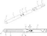
도 1은 종래 전자담배의 카트리지 구조를 설명하기 위한 도면이다.
도 2a, 2b는 본 발명의 제1 실시 예로 나타낸 카트리지 구조이다.
도 3a는 본 발명의 제2 실시 예로 나타낸 카트리지 구조이다.
도 3b는 본 발명의 제3 실시 예로 나타낸 카트리지 구조이다.
도 4a, 4b는 본 발명의 제4 실시 예로 나타낸 카트리지 구조이다.
도 5a, 5b는 본 발명의 제1 실시 예로 나타낸 카트리지 구조이다.1 is a view for explaining the cartridge structure of a conventional electronic cigarette.
2A and 2B are cartridge structures shown in the first embodiment of the present invention.
3A is a cartridge structure shown in the second embodiment of the present invention.
3B is a cartridge structure shown in the third embodiment of the present invention.
4A and 4B are cartridge structures shown in the fourth embodiment of the present invention.
5A and 5B are cartridge structures shown in the first embodiment of the present invention.
이하, 본 발명의 바람직한 실시 예를 첨부된 예시 도면에 의거 상세히 설명하면 다음과 같다.Hereinafter, preferred embodiments of the present invention will be described in detail with reference to the accompanying drawings.
먼저, 본 발명에 따른 카트리지는 금연 보조기의 조성물 용액이 적재되거나, 전자담배의 니코틴 용액이 적재되기 위한 원통형 구조의 하우징을 포함하고, 하우징의 일단에는 무화기와 결합하여, 용액을 무화기로 공급하기 위한 노즐이 구비되고, 타단에는 무화기로부터 생성된 기화물질을 흡입하기 위한 마우스피스가 장착된다. 상기 마우스피스는 중앙에 흡입홀을 구비하며, 흡입홀은 하우징의 외주면을 따라 상기 무화기와 연통하는 구조이다.First, the cartridge according to the present invention includes a housing having a cylindrical structure for loading the composition solution of the smoking cessation aid or the nicotine solution of the electronic cigarette, and coupled to the atomizer at one end of the housing, for supplying the solution to the atomizer. A nozzle is provided, and the other end is equipped with a mouthpiece for sucking the vaporized material generated from the atomizer. The mouthpiece has a suction hole in the center, the suction hole is in communication with the atomizer along the outer peripheral surface of the housing.
한편, 본 발명에서는 카트리지 일단에 장착되어 외력에 의해 카트리지 내부의 공기를 상기 노즐을 통해 배출되도록 하는 푸쉬 수단이 형성되어, 푸쉬 수단의 동작에 따라 카트리지 내부에 적재된 용액이 노즐을 통해 일정 용량으로 배출된다. 여기서, 상기 푸쉬 수단은 탄성체를 이용하거나, 탄성부재를 접목시켜 탄성력으로 인한 복원력을 형성할 수 있는 버튼 구조이다.On the other hand, in the present invention, a push means is mounted on one end of the cartridge to discharge the air inside the cartridge through the nozzle by an external force, so that the solution loaded inside the cartridge according to the operation of the push means has a predetermined capacity through the nozzle. Discharged. Here, the push means is a button structure that can use the elastic body, or by grafting the elastic member to form a restoring force due to the elastic force.
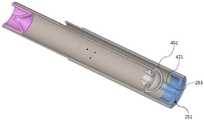
도 2a는 본 발명의 제1 실시 예로서 카트리지를 나타낸 사시도이다. 도시된 바와 같이, 카트리지(200)는 일측이 개방된 원통형 구조로 용액이 적재되고 금연보조기 또는 전자담배의 무화기로 삽설되는 삽설관(215)과, 상기 삽설관(215)의 타측으로 일부가 중첩되도록 상기 삽설관(215)을 수용하되, 상기 삽설관(215)의 외주부와 연통된 연통구(217)를 갖는 권취관(213)으로 구성된 하우징(211)을 포함하며, 상기 삽설관(215)의 일측으로 체결되어 상기 용액을 무화기로 배출하는 노즐(261)과, 상기 노즐(261)과 대향되도록 권취관(213)의 타측으로 결합되고 상기 연통구(217)와 연통되어 기화 물질을 흡입하도록 흡입홀(253)이 마련된 마우스피스(251)와, 상기 삽설관(215) 및 권취관(213)의 중첩 위치에 설치되며, 외부 가압력에 의해 상기 삽설관(215) 내부 압력을 일시적으로 증가시켜, 상기 용액이 노즐(261)을 통해 일정량 배출되도록 유도하도록 탄성 재질의 플라스틱으로 성형되는 푸쉬 수단(231)을 포함한다.2A is a perspective view showing a cartridge as a first embodiment of the present invention. As shown, the
여기서, 상기 하우징(211) 및 푸쉬 수단(231)은 PB(Polybutylene) 재질로 성형됨이 바람직하며, 상기 푸쉬 수단(231)의 성형 두께를 줄여 탄성을 유도한다. 상기 푸쉬 수단(231)은 탄성 구조를 갖도록 하기 위해, PB(Polybutylene) 재질로서 평탄 구조를 갖고 상측면에 돌기(233)를 형성할 수 있다. 즉, 상기 푸쉬 수단(231)은 돌기(233)를 가압함으로써, 삽설관(215) 내부의 용적을 줄여 용액이 노즐(261)을 통해 무화기로 배출되는 구조이다.Here, the
따라서, 상기 푸쉬 수단(231)과 하우징(211)은 서로 다른 재질로 사출해야 하며, 본 발명에서는 이중사출 방식을 이용한 일체형 성형이 바람직하다. 필요에 따라, 서로 다른 재질을 각각 사출한 후, 접합(Bonding) 시켜 제조할 수 있음은 당연할 것이다.Therefore, the push means 231 and the
도 2b는 본 실시 예에 따른 카트리지의 단면을 나타낸 도면이다. 도시된 바와 같이, 일측이 개방된 삽설관(215)으로 노즐(261)이 장착되고, 상기 권취관(213)은 삽설관(215)을 일부 수용하도록 삽설관(215)과 권취관(213) 사이로 연통구(217)를 형성하며, 연통구(217)는 권취관(213)의 타측에 장착된 마우스피스(251)와 연통되는 구조이다. 따라서, 상기 삽설관(215)이 무화기에 삽입 설치될 때, 상기 연통구(217)는 무화기에 인입되며, 무화기를 통해 기화되는 기화물질이 연통구(217)를 거쳐 상기 권취관(213) 및 마우스피스(251)의 흡입홀(253)로 공급된다.2B is a view showing a cross section of the cartridge according to the present embodiment. As shown, the
여기서, 상기 푸쉬 수단(231)은 삽설관(215) 및 권취관(213)의 중첩 위치에서 PB 재질로 성형함에 따라, 사용자가 돌기(233)를 이용하여 푸쉬 수단(231)을 가압할 경우, 삽설관(215) 내부에 적재된 용액이 상기 노즐(261)을 통해 무화기로 공급된다. 즉, 사용자가 권취관(213)을 파지하여 끽연을 할 경우, 파지 과정에서 간헐적으로 돌기(233)를 가압하며, 푸쉬 수단(231)의 탄성으로 인해 삽설관(215)의 용적이 줄게 된다. 따라서, 푸쉬 수단(231)은 삽설관(215)의 내부 공기를 가압하고, 이는 적재된 용액이 삽설관(215)의 용적 변화에 대응하여 노즐(261)을 통해 무화기로 배출된다.Here, when the push means 231 is formed of a PB material in the overlapping position of the
금연보조기 또는 전자담배를 사용할 경우, 용액 공급은 휴지 상태 즉, 카트리지가 하향으로 기울어진 상태에서 이루어지기 때문에, 노즐(261)을 통해 용액만을 일정량 공급할 수 있다. 물론, 삽설관(215) 내부에 적재되는 용액의 용량에 따라, 배출되는 용액의 용량이 가변될 수 있으나, 상기 노즐(261)의 용량과 푸쉬 수단(231)의 용적 변화량의 차이는 매우 크기 때문에, 용액의 배출 오차는 미비하게 된다.In the case of using the smoking cessation aid or the electronic cigarette, since the solution supply is at rest, that is, the cartridge is inclined downward, only a predetermined amount of the solution may be supplied through the
본 발명에 따른 카트리지의 삽설관(215)은 직경 8mm이고, 길이가 37mm로서, 노즐(261)을 제외한 용액의 적재되는 공간은 1858.88㎣이다. 이에 노즐의 관통구 직경은 0.4mm, 길이 1.2mm로서 체적은 0.48㎣이고, 삽설관(215) 내부 공간을 가압하는 상기 푸쉬 수단(231)의 두께는 0.15mm 내지 0.22mm이며, 길이는 18mm × 5mm로서 면적은 90㎟이다. 상기 푸쉬 수단(231)이 곡률 형태로 가압되고, 곡률 직경이 50mm일 경우, 푸쉬 수단(231)에 의해 삽설관(215)의 용적 변화량은 대략 580㎣이며, 노즐의 관통구 직경 대비 삽설관의 용적 변화량 비율은 1208배이다. 따라서, 삽설관(215) 내부에 적재된 용액이 적더라도, 푸쉬 수단(231)의 가압력은 용액을 노즐을 통해 배출되도록 가압하며, 적재 용액의 용량에 큰 변화 없이 일정 용량의 용액을 배출하게 된다.The
도 3a는 본 발명의 다른 실시 예로 나타낸 카트리지 사시도이다. 도시된 바와 같이, 푸쉬 수단(231)의 형상이 변형된 것으로, PB 재질의 하우징(211)과 더불어, 실리콘 재질의 푸쉬 수단(231)을 제시할 수 있다.Figure 3a is a perspective view of the cartridge shown in another embodiment of the present invention. As illustrated, the shape of the push means 231 is modified, and together with the
즉, 카트리지(200)는 일측이 개방된 원통형 구조로 용액이 적재되고 금연보조기 또는 전자담배의 무화기로 삽설되는 삽설관(215)과, 상기 삽설관(215)의 타측으로 일부가 중첩되도록 상기 삽설관(215)을 수용하되, 상기 삽설관(215)의 외주부와 연통된 연통구(217)를 갖는 권취관(213)으로 구성된 하우징(211)을 포함하며, 상기 삽설관(215)의 일측으로 체결되어 상기 용액을 무화기로 배출하는 노즐(261)과, 상기 노즐(261)과 대향되도록 권취관(213)의 타측으로 결합되고 상기 연통구(217)와 연통되어 기화 물질을 흡입하도록 흡입홀(253)이 마련된 마우스피스(251)와, 상기 삽설관(215) 및 권취관(213)의 중첩 위치에 설치되며, 외부 가압력에 의해 상기 삽설관(215)의 용적을 가변시켜 상기 용액이 노즐(261)을 통해 배출되도록 유도하는 실리콘 재질의 푸쉬 수단(231)으로 이루어진다.That is, the
여기서, 실리콘 재질의 푸쉬 수단(231)은 용액이 적재되는 삽설관(215)과 연통하도록 끼움 결합된 후, 소정의 본딩 과정을 거쳐 하우징(211)과 일체화된 구조로 제조된다. 상기 실리콘 재질은 그 경도를 조절하여 제조할 수 있으나, 전술된 PB 재질보다 경도가 낮게 성형함으로써, 외관의 미려함과 더불어 사용의 편의성을 높일 수 있다.Here, the push means 231 of the silicon material is fitted to communicate with the
상기 실리콘 재질의 푸쉬 수단(231)은 삽설관(215)의 일측 외주면 상으로 관통홀을 형성하고, 상기 관통홀의 내주면과 푸쉬 수단(231)의 외주부를 접합하는 구조이다. 따라서, 푸쉬 수단(231)과 삽설관(215) 사이에는 밀폐된 구조로서, 푸쉬 수단(231)을 가압 시 상기 삽설관(215)의 내부 용적을 축소시킴으로써, 삽설관(215)에 적재된 용액이 노즐(261)을 통해 배출되도록 한다. 또한, 상기 실리콘 재질의 푸쉬 수단(231)은 도시된 바와 같이, 하우징(211)의 외주부 일단에 장착되고 있으나, 상기 연통구(217)를 회피하여 적어도 둘 이상이 대향하도록 설치될 수 있다.The silicon push means 231 has a through hole formed on one outer circumferential surface of the
한편, 도 3b는 푸쉬 수단(231)이 튜브 형태로 구현됨을 나타낸 도면이며, 상기 삽설관(215)에 내설되고 일단이 상기 노즐(261)과 접합된 튜브 구조로서, 튜브의 외주부 일단에는 노브를 형성하되, 노브가 관통홀을 통해 돌출된다.On the other hand, Figure 3b is a view showing that the push means 231 is implemented in the form of a tube, the tube structure is built in the
즉, 도시된 바와 같이 카트리지(200)는 일측이 개방된 원통형 구조로 용액이 적재되고 금연보조기 또는 전자담배의 무화기로 삽설되는 삽설관(215)과, 상기 삽설관(215)의 타측으로 일부가 중첩되도록 상기 삽설관(215)을 수용하되, 상기 삽설관(215)의 외주부와 연통된 연통구(217)를 갖는 권취관(213)으로 구성되며, 상기 삽설관(215)이 외부와 연통가능한 관통홀(311)이 구비되는 하우징(211)과, 상기 삽설관(215)의 일측으로 체결되어 상기 용액을 무화기로 배출하는 노즐(261)과, 상기 노즐(261)과 대향되도록 권취관(213)의 타측으로 결합되고 상기 연통구(217)와 연통되어 기화 물질을 흡입하도록 흡입홀(253)이 마련된 마우스피스(251)와, 일단으로 개구면을 갖고, 상기 개구면에 노즐(261)이 접합된 후, 상기 삽설관(215)에 내설되어 용액이 충진되며, 관통홀(311)을 통해 외부 가압력이 인가될 때, 충진된 용액이 노즐(261)을 통해 배출되는 튜브(321)가 포함된 푸쉬 수단(231)으로 이루어진다.That is, as shown, the
상기 튜브(321)는 상기 관통홀(311)과 대향되는 위치에서 돌출 연장되는 노브(323)을 형성한다. 따라서, 상기 노브(323)에 외력이 가압될 때, 상기 튜브(321)는 탄성력을 갖고 외형이 변형되어, 튜브(323) 내에 적재된 용액을 상기 노즐(261)로 배출한다. 상기 튜브(321) 또한 인체에 무해한 실리콘 재질로 성형됨이 바람직할 것이나, 필요에 따라 고무재질로 성형될 수 있다.The
이와 같이, 본 발명에서 용액을 적재하기 위한 구조로서 튜브 형태가 가능한 것은, 본 발명에서 제시되는 카트리지가 1회용으로 적용되기 때문이다. 이는 별도의 충진 밸브를 형성하지 않아 제조의 편의성 및 내구성을 높일 뿐만 아니라, 용액의 노출을 방지하여 제품의 안정성을 확보할 수 있게 된다.As such, the tubular shape is possible as the structure for loading the solution in the present invention, because the cartridge presented in the present invention is applied for single use. This does not form a separate filling valve to increase the convenience and durability of the manufacturing, as well as to prevent the exposure of the solution to ensure the stability of the product.
도 4a는 본 발명의 다른 실시 예로서, 상기 푸쉬 수단(231)이 카트리지(200)의 후방에 설치되어 마우스피스(251)를 통해 삽설관(211) 내부가 가압되는 밸로우즈(Bellows) 타입으로 제시됨을 보이고 있다.4A illustrates a bellows type in which the push means 231 is installed at the rear of the
즉, 도시된 바와 같이 카트리지(200)는 양단이 개방된 원통형 구조로 용액이 적재되고 금연보조기 또는 전자담배의 무화기로 삽설되는 삽설관(215)과, 상기 삽설관(215)의 일부가 중첩되도록 상기 삽설관(215)을 수용하되, 상기 삽설관(215)의 외주부와 연통된 연통구(217)를 갖는 권취관(213)으로 이루어진 하우징(211)과, 상기 삽설관(215)의 일측으로 체결되어 상기 용액을 무화기로 배출하는 노즐(261)과, 상기 노즐(261)과 대향되도록 권취관(213)의 타측으로 결합되고 상기 연통구(217)와 연통되어 기화 물질을 흡입하도록 흡입홀(253)이 마련된 마우스피스(251)와, 상기 삽설관(215)의 타측으로 체결되고 상기 마우스피스(251)에 의해 가압되어 삽설관(215)에 적재된 용액이 상기 노즐(261)을 통해 배출되는 푸쉬 수단(231)으로 구성된다.That is, as shown, the
상기 푸쉬 수단(231)은 고무 또는 실리콘과 같은 탄성 재질로 성형되고 다수의 주름을 포함하며, 압축 공기를 상기 삽설관(215) 내부로 공급하는 벨로우즈(bellows:401) 구조이다. 상기 벨로우즈(401)는 개구면을 갖는 전방이 삽설관(215)의 타단과 접합되어 밀폐되며, 슬라이드 유동이 가능한 마우스피스(251)는 상기 벨로우즈(401)의 후방에 접촉된다.The push means 231 is formed of an elastic material such as rubber or silicone and includes a plurality of pleats, and has a bellows (401) structure for supplying compressed air into the
따라서, 상기 마우스피스(251)를 외력에 의해 가압할 경우, 마우스피스(251)가 상기 벨로우즈(401)를 가압함으로써, 삽설관(215) 내부의 공기를 가압한다. 이는 삽설관(215)에 적재된 용액을 가압하여, 용액이 노즐(261)을 통해 배출되도록 유도하는 것이다. 이후, 마우스피스(251)의 외력이 상실될 때, 벨로우즈(401)의 구조적 물성인 탄지력에 의해 마우스피스(251)가 원위치로 복귀한다.Therefore, when the
한편, 상기 벨로우즈(401)는 구조적 특성상 압축 탄성을 보유하고 있으나, 이에 대한 반응속도가 저하되기 때문에, 별도의 탄성 스프링을 장착할 수 있을 것이다. 이는 도시된 바와 같이, 상기 삽설관(215)의 타측단과 마우스피스(251) 사이로 스프링(403)을 장착하여, 마우스피스(251)의 가압력에 대응하는 탄성을 충분히 보유하도록 할 수 있다. 필요에 따라, 상기 스프링(403)은 벨로우즈(401) 내부에 장착되거나, 벨로우즈(401)의 외피에 밀착 설치될 수 있을 것이다.On the other hand, the
도 4b는 도 4a의 내부의 주요 구성을 설명하기 위한 도면이다. 도시된 바와 같이, 상기 권취관(213)과 삽설관(215) 사이에 연통구(217)가 마련되며, 연통구(217)는 상기 마우스피스(251)의 흡입홀(253)과 연통한다. 이에, 상기 흡입홀(253)의 종단은 상기 밸로우즈(401)의 후방에 밀착되나, 흡입홀(253)의 종단부 일측에 연통홈(403)이 마련된다. 따라서, 상기 연통구(217)를 통해 유입되는 기화 물질은 권취관(213)의 내부를 따라 마우스피스(251)로 공급되고, 상기 연통홈(421)을 거쳐 흡입홀(253)로 흡입된다. 이로 인해, 상기 흡입홀(253)과 밸로우즈(401) 간 밀착된 구조임에도 불구하고, 상기 연통홈(403)에 의해 기화물질을 흡입할 수 있는 것이다.FIG. 4B is a diagram for explaining a main configuration of the inside of FIG. 4A. As shown, a
본 실시 예에서 적용되는 밸로우즈(401)는 그 크기(용량)에 따라 상기 스프링(403)의 장착 여부를 결정할 수 있는데, 용량이 큰 밸로우즈(401)의 경우 고유 탄성에 의한 복원력이 크기 때문에, 별도의 스프링이 장착되지 않지만, 카트리지의 용량, 크기에 따라 작은 용량의 밸로우즈(401)를 사용할 경우, 스프링이 장착됨이 바람직할 것이다.The
한편, 본 실시 예에서 제시되는 푸쉬 수단(231)을 벨로우즈(401)로 제한하였으나, 벨로우즈(401) 이외에 반구형태를 갖는 에어백으로 사용될 수 있다. 도 5에 도시된 바와 같이, 상기 에어백(451)의 평면은 삽설관(215)의 타단에 밀착 고정되어 개구부를 형성하고, 곡면은 밀폐된 구조로서 상기 마우스피스(251)와 밀착된다. 또한, 상기 마우스피스(251)의 흡입홀(253) 종단은 전술된 바와 같이 연통홈(403)을 형성함에 따라, 연통구(217)를 통해 유입되는 기화물질을 흡입할 수 있도록 한다.On the other hand, the push means 231 presented in the present embodiment is limited to the
여기서, 상기 에어백(451)은 삽설관(215)의 타단에 관통구를 형성하고, 관통구와 에어백(451)의 평면과 밀착되는데, 필요에 따라 삽설관(215)의 관통구와 에어백(451)의 개구부가 대응하도록 접합되거나, 또는 에어백(451)의 평면에 형성된 개구부가 돌출 연장되도록 성형한 후, 상기 관통구에 삽설 및 접합할 수 있다. 본 실시 예에서 또한 상기 마우스피스(251)는 외부로 이탈되지 않는 범위 내에서 권취관(213)의 내주면을 따라 소정 거리 슬라이드 유동한다. 상기 마우스피스(251)는 에어백(451)의 탄지력에 의해 외향되게 가압된 상태를 유지하며, 사용자가 마우스피스(251)를 내향으로 가압할 경우, 상기 에어백(451)이 수축되어 상기 삽설관(215)으로 공기압이 전달된다. 따라서, 상기 삽설관(215)에 적재된 용액은 노즐(261)을 통해 외부로 배출된다.
Here, the
전술된 바와 같이, 본 발명에 따른 카트리지는 외력에 의한 가압력을 이용하여 적재된 용액이 노즐을 통해 일정량 배출되도록 함에 따라, 무화기를 통해 기화되는 용액을 일정하게 유지할 수 있으며, 이로 인해 과다한 용액 배출로 인한 용액의 흡입을 방지하고, 과소한 용액 배출로 인한 불필요한 요소의 연소를 방지하여 위해 요소를 사전에 방지한다. 따라서, 본 발명에서 제시되는 카트리지는 사용자에 대한 인체 유해요소가 억제되어 국민건강을 도모하기 때문에, 산업적 이용가치가 충분히 높을 것으로 판단된다.
As described above, the cartridge according to the present invention by using the pressing force by the external force is to discharge a certain amount through the nozzle, it is possible to maintain a constant vaporized solution through the atomizer, thereby causing excessive solution discharge It prevents the inhalation of the solution due to, and prevents the burning of unnecessary elements due to excessive discharge of the solution to prevent the element in advance. Therefore, since the cartridge presented in the present invention promotes public health by suppressing harmful factors to the user, it is judged that the industrial use value is sufficiently high.
200 : 카트리지211 : 하우징
213 : 권취관215 : 삽설관
217 : 연통구231 : 푸쉬 수단
233 : 돌기251 : 마우스피스
253 : 흡입홀261 : 노즐
311 : 관통홀321 : 튜브
323 : 노브401 : 벨로우즈
403 : 스프링421 : 연통홈
451 : 에어백200: cartridge 211: housing
213: winding tube 215: intubation tube
217: communication port 231: push means
233: projection 251: mouthpiece
253: suction hole 261: nozzle
311: through hole 321: tube
323: knob 401: bellows
403: spring 421: communication groove
451: Airbag
Claims (10)
Translated fromKorean일측이 개방된 원통형 구조로 용액이 적재되고 금연보조기 또는 전자담배의 무화기로 삽설되는 삽설관(215);
상기 삽설관(215)의 타측으로 일부가 중첩되도록 상기 삽설관(215)을 수용하되, 상기 삽설관(215)의 외주부와 연통된 연통구(217)를 갖는 권취관(213)으로 구성된 하우징(211);
상기 삽설관(215)의 일측으로 체결되어 상기 용액을 무화기로 배출하는 노즐(261);
상기 노즐(261)과 대향되도록 권취관(213)의 타측으로 결합되고 상기 연통구(217)와 연통되어 기화 물질을 흡입하도록 흡입홀(253)이 마련된 마우스피스(251); 및
상기 삽설관(215)의 내부와 연통하여 외부 가압력에 의해 상기 삽설관(215) 내부 압력을 일시적으로 증가시켜, 상기 용액이 노즐(261)을 통해 일정량 배출되도록 유도하는 푸쉬 수단(231)으로 이루어진 것을 특징으로 하는 금연보조기의 수동 주입 노즐형 카트리지.In the nozzle type cartridge for manually discharging the loading solution of the smoking aid or electronic cigarette,
Insertion tube 215, the solution is loaded into a cylindrical structure open on one side and inserted into the atomizer of the smoking cessation aid or electronic cigarette;
A housing composed of a winding tube 213 which accommodates the inserting tube 215 so that a part of the inserting tube 215 overlaps with the other side of the inserting tube 215, and has a communication port 217 communicating with an outer circumferential portion of the inserting tube 215 ( 211);
A nozzle 261 fastened to one side of the intubation tube 215 to discharge the solution to the atomizer;
A mouthpiece 251 coupled to the other side of the winding tube 213 so as to face the nozzle 261 and communicating with the communication port 217 and provided with a suction hole 253 for sucking vaporized material; And
The push means 231 communicates with the inside of the insertion tube 215 to temporarily increase the internal pressure of the insertion tube 215 by an external pressing force, thereby inducing the solution to be discharged through a nozzle 261. Manual injection nozzle type cartridge of the smoking cessation aid.
상기 푸쉬 수단(231)은 상기 삽설관(215) 및 권취관(213)의 중첩 위치에 설치되며, 탄성 재질의 플라스틱으로 평탄 구조를 갖고, 중앙 위치에 돌기(233)가 형성된 것을 특징으로 하는 금연보조기의 수동 주입 노즐형 카트리지.The method of claim 1,
The push means 231 is installed in the overlapping position of the insertion pipe 215 and the winding pipe 213, has a flat structure of plastic of elastic material, characterized in that the non-smoking characterized in that the projection 233 is formed in the center position Manual injection nozzle cartridge of the brace.
상기 상기 하우징(211) 및 푸쉬 수단(231)은 PB(Polybutylene), PE(Polyethylene) PP(Polypropylene) 중 어느 하나의 재질로서 성형되는 것을 특징으로 하는 금연보조기의 수동 주입 노즐형 카트리지.The method of claim 2,
The housing (211) and the push means (231) is a manual injection nozzle type cartridge of a smoking cessation aid, characterized in that formed from any one of the material of polybutylene (PB), polyethylene (PP) polypropylene (PP).
상기 푸쉬 수단(231)은 상기 삽설관(215) 및 권취관(213)의 중첩 위치에 설치되며, 실리콘 재질로 성형되어 상기 하우징(211)과 일체화된 것을 특징으로 하는 금연보조기의 수동 주입 노즐형 카트리지.The method of claim 1,
The push means 231 is installed at the overlapping position of the insertion tube 215 and the winding tube 213, and is formed of a silicone material and is integrated with the housing 211, the manual injection nozzle type of the smoking cessation aid cartridge.
상기 푸쉬 수단(231)은 대향되도록 두 개가 설치되는 것을 특징으로 하는 금연보조기의 수동 주입 노즐형 카트리지.The method of claim 4, wherein
Manual injection nozzle type cartridge of the smoking cessation aid, characterized in that the two push means 231 are installed so as to face each other.
일단으로 개구면을 갖고, 상기 개구면에 노즐(261)이 접합된 후, 상기 삽설관(215)에 내설되어 용액이 충진되며, 외부 가압력이 인가될 때 충진된 용액을 노즐(261)로 배출시키는 튜브(321)가 더 포함되는 것을 특징으로 하는 금연보조기의 수동 주입 노즐형 카트리지.The method of claim 1 wherein the push means 231,
It has an opening surface at one end, and after the nozzle 261 is bonded to the opening surface, it is built in the insertion tube 215 to fill the solution, and discharges the filled solution to the nozzle 261 when an external pressing force is applied. Manual injection nozzle type cartridge of the smoking cessation aid, characterized in that it further comprises a tube 321.
상기 삽설관(215) 및 권취관(213)의 중첩 위치에 관통홀(311)이 형성되고, 상기 튜브(321)는 상기 관통홀(311)과 대응되는 위치에서 돌출 연장되도록 노브(323)를 형성하는 것을 특징으로 하는 금연보조기의 수동 주입 노즐형 카트리지.The method according to claim 6,
A through hole 311 is formed at an overlapping position of the insertion tube 215 and the winding tube 213, and the tube 321 is provided with a knob 323 to protrude and extend at a position corresponding to the through hole 311. Manual injection nozzle type cartridge of the smoking cessation aid, characterized in that forming.
상기 마우스피스(251)는 삽설관(215)의 내부면을 따라 슬라이드 유동되며;
상기 푸쉬 수단(231)은, 상기 삽설관(215)의 타측으로 체결되고 상기 마우스피스(251)에 의해 가압되어 삽설관(215)에 적재된 용액이 상기 노즐(261)을 통해 배출되도록 다수의 주름을 갖는 탄성 재질의 벨로우즈(bellows:401)이고;
상기 벨로우즈(401)는 개구면을 갖는 전방이 삽설관(215)의 타단과 접합되어 밀폐되며, 상기 마우스피스(251)는 상기 벨로우즈(401)의 후방에 접촉하는 것을 특징으로 하는 금연보조기의 수동 주입 노즐형 카트리지.The method of claim 1,
The mouthpiece 251 slides along the inner surface of the intubation tube 215;
The push means 231 is fastened to the other side of the intubation tube 215 and pressurized by the mouthpiece 251 so that the solution loaded in the intubation tube 215 is discharged through the nozzle 261. Bellows 401 of elastic material having pleats;
The bellows 401 is closed in front of the bellows 401 is joined with the other end of the intubation tube 215, the mouthpiece 251 is in contact with the rear of the bellows 401 manual Injection nozzle cartridge.
상기 마우스피스(251)는 삽설관(215)의 내부면을 따라 슬라이드 유동되며;
상기 푸쉬 수단(231)은, 상기 삽설관(215)의 타측으로 체결되고 상기 마우스피스(251)에 의해 가압되어 삽설관(215)에 적재된 용액이 상기 노즐(261)을 통해 배출되도록 반구 형상을 갖고 탄성 재질로 이루어진 에어백(451)이고;
상기 에어백(451)은 개구면을 갖는 전방이 삽설관(215)의 타단과 접합되어 밀폐되며, 상기 마우스피스(251)는 상기 에어백(451)의 후방에 접촉하는 것을 특징으로 하는 금연보조기의 수동 주입 노즐형 카트리지.The method of claim 1,
The mouthpiece 251 slides along the inner surface of the intubation tube 215;
The push means 231 is fastened to the other side of the insertion tube 215 and pressurized by the mouthpiece 251 so that the solution loaded in the insertion tube 215 is discharged through the nozzle 261 An airbag 451 having an elastic material;
The airbag 451 is closed in front of the airbag 451 is joined with the other end of the insertion tube 215, the mouthpiece 251 is in contact with the rear of the airbag 451, manual Injection nozzle cartridge.
상기 삽설관(215)의 타단과 상기 마우스피스(251) 사이에 스프링(403)이 장착되는 것을 특징으로 하는 금연보조기의 수동 주입 노즐형 카트리지.10. The method according to claim 8 or 9,
Manual injection nozzle type cartridge of the smoking cessation aid, characterized in that the spring (403) is mounted between the other end of the insertion tube (215) and the mouthpiece (251).
Priority Applications (1)
| Application Number | Priority Date | Filing Date | Title |
|---|---|---|---|
| KR1020110062581AKR20130001750A (en) | 2011-06-28 | 2011-06-28 | Nozzle type cartridge having a function of manual injection for quit smoking auxiliary appratus |
Applications Claiming Priority (1)
| Application Number | Priority Date | Filing Date | Title |
|---|---|---|---|
| KR1020110062581AKR20130001750A (en) | 2011-06-28 | 2011-06-28 | Nozzle type cartridge having a function of manual injection for quit smoking auxiliary appratus |
Publications (1)
| Publication Number | Publication Date |
|---|---|
| KR20130001750Atrue KR20130001750A (en) | 2013-01-07 |
Family
ID=47834646
Family Applications (1)
| Application Number | Title | Priority Date | Filing Date |
|---|---|---|---|
| KR1020110062581AAbandonedKR20130001750A (en) | 2011-06-28 | 2011-06-28 | Nozzle type cartridge having a function of manual injection for quit smoking auxiliary appratus |
Country Status (1)
| Country | Link |
|---|---|
| KR (1) | KR20130001750A (en) |
Cited By (9)
| Publication number | Priority date | Publication date | Assignee | Title |
|---|---|---|---|---|
| CN103504480A (en)* | 2013-09-30 | 2014-01-15 | 赵洪伟 | Machine for self-help smoking quitting |
| CN103519350A (en)* | 2013-10-15 | 2014-01-22 | 深圳市合元科技有限公司 | Electronic cigarette atomization device, battery device and electronic cigarette |
| KR101461138B1 (en)* | 2013-06-12 | 2014-11-20 | 이재홍 | Tobacco for stopping smoking having nozzles worked by button |
| EP3005889A4 (en)* | 2013-05-28 | 2017-03-29 | Kimree Hi-Tech Inc. | Thermoplastic elastomer composite material, electronic cigarette component, and method for manufacturing the electronic cigarette component |
| WO2019211321A1 (en)* | 2018-05-01 | 2019-11-07 | Nerudia Limited | Consumable for smoking substitute device |
| KR20210088390A (en)* | 2020-01-06 | 2021-07-14 | 주식회사 케이티앤지 | Aerosol generating device |
| US12022880B2 (en) | 2020-01-06 | 2024-07-02 | Kt&G Corporation | Aerosol generating device preventing reuse of an aerosol generating article by detecting discoloration of a wrapper of the aerosol generating article |
| US12059029B2 (en) | 2020-01-06 | 2024-08-13 | Kt&G Corporation | Aerosol generating device with a cutting portion |
| US12408699B2 (en) | 2020-01-06 | 2025-09-09 | Kt&G Corporation | Aerosol generating device |
- 2011
- 2011-06-28KRKR1020110062581Apatent/KR20130001750A/ennot_activeAbandoned
Cited By (11)
| Publication number | Priority date | Publication date | Assignee | Title |
|---|---|---|---|---|
| EP3005889A4 (en)* | 2013-05-28 | 2017-03-29 | Kimree Hi-Tech Inc. | Thermoplastic elastomer composite material, electronic cigarette component, and method for manufacturing the electronic cigarette component |
| KR101461138B1 (en)* | 2013-06-12 | 2014-11-20 | 이재홍 | Tobacco for stopping smoking having nozzles worked by button |
| CN103504480A (en)* | 2013-09-30 | 2014-01-15 | 赵洪伟 | Machine for self-help smoking quitting |
| CN103504480B (en)* | 2013-09-30 | 2016-01-20 | 赵洪伟 | Self-service smoking cessation machine |
| CN103519350A (en)* | 2013-10-15 | 2014-01-22 | 深圳市合元科技有限公司 | Electronic cigarette atomization device, battery device and electronic cigarette |
| CN103519350B (en)* | 2013-10-15 | 2016-01-27 | 深圳市合元科技有限公司 | Electronic cigarette atomization device, cell apparatus and electronic cigarette |
| WO2019211321A1 (en)* | 2018-05-01 | 2019-11-07 | Nerudia Limited | Consumable for smoking substitute device |
| KR20210088390A (en)* | 2020-01-06 | 2021-07-14 | 주식회사 케이티앤지 | Aerosol generating device |
| US12022880B2 (en) | 2020-01-06 | 2024-07-02 | Kt&G Corporation | Aerosol generating device preventing reuse of an aerosol generating article by detecting discoloration of a wrapper of the aerosol generating article |
| US12059029B2 (en) | 2020-01-06 | 2024-08-13 | Kt&G Corporation | Aerosol generating device with a cutting portion |
| US12408699B2 (en) | 2020-01-06 | 2025-09-09 | Kt&G Corporation | Aerosol generating device |
Similar Documents
| Publication | Publication Date | Title |
|---|---|---|
| KR20130001750A (en) | Nozzle type cartridge having a function of manual injection for quit smoking auxiliary appratus | |
| JP7016395B2 (en) | Cartridges, battery units and e-cigarettes | |
| CN113329647B (en) | Aerosol delivery device | |
| JP7326158B2 (en) | Refillable aerosol delivery device and related methods | |
| RU2714784C1 (en) | Electronic vapour delivery system | |
| US11160306B2 (en) | Electronic smoking device having a pump mechanism | |
| CN108289510B (en) | Electrically operated aerosol-generating system with liquid pump | |
| US11937637B2 (en) | Aerosol source for a vapor provision system | |
| JP4739322B2 (en) | Electronic atomized tobacco | |
| KR101426352B1 (en) | Electronic cigarette | |
| KR101084048B1 (en) | Electronic cigarette | |
| IL272286B2 (en) | A cartridge for an aerosol-generating system | |
| KR20190139255A (en) | Aerosol delivery device with ceramic wicking element | |
| US20190216134A1 (en) | Syringe refiller for an electronic smoking device | |
| KR101094727B1 (en) | Electronic cigarette | |
| RU2740761C1 (en) | Steam generation systems | |
| CN104254356A (en) | Electronic smoking article | |
| US20200397059A1 (en) | Lava2 Vaporizer Device and Cartridge System | |
| CN113613517A (en) | Flow directing member for a vapor supply system | |
| KR20130031550A (en) | Cartridge with separated volume for electric cigarette | |
| KR200454619Y1 (en) | E-cigarette cartridge | |
| EP3840166A1 (en) | Aerosol delivery device/system | |
| EP3838025A1 (en) | Aerosol delivery device | |
| EP3838020A1 (en) | Aerosol delivery device/system | |
| CN118102937A (en) | Aerosol delivery device/system |
Legal Events
| Date | Code | Title | Description |
|---|---|---|---|
| A201 | Request for examination | ||
| PA0109 | Patent application | Patent event code:PA01091R01D Comment text:Patent Application Patent event date:20110628 | |
| PA0201 | Request for examination | ||
| PG1501 | Laying open of application | ||
| E902 | Notification of reason for refusal | ||
| PE0902 | Notice of grounds for rejection | Comment text:Notification of reason for refusal Patent event date:20130201 Patent event code:PE09021S01D | |
| E701 | Decision to grant or registration of patent right | ||
| PE0701 | Decision of registration | Patent event code:PE07011S01D Comment text:Decision to Grant Registration Patent event date:20130822 | |
| PC1904 | Unpaid initial registration fee |