KR20120131788A - Inertial Sensor And Method of Manufacturing The Same - Google Patents
Inertial Sensor And Method of Manufacturing The SameDownload PDFInfo
- Publication number
- KR20120131788A KR20120131788AKR1020110050200AKR20110050200AKR20120131788AKR 20120131788 AKR20120131788 AKR 20120131788AKR 1020110050200 AKR1020110050200 AKR 1020110050200AKR 20110050200 AKR20110050200 AKR 20110050200AKR 20120131788 AKR20120131788 AKR 20120131788A
- Authority
- KR
- South Korea
- Prior art keywords
- patterning
- membrane
- substrate
- mass
- inertial sensor
- Prior art date
- Legal status (The legal status is an assumption and is not a legal conclusion. Google has not performed a legal analysis and makes no representation as to the accuracy of the status listed.)
- Withdrawn
Links
Images


Classifications
- B—PERFORMING OPERATIONS; TRANSPORTING
- B81—MICROSTRUCTURAL TECHNOLOGY
- B81C—PROCESSES OR APPARATUS SPECIALLY ADAPTED FOR THE MANUFACTURE OR TREATMENT OF MICROSTRUCTURAL DEVICES OR SYSTEMS
- B81C1/00—Manufacture or treatment of devices or systems in or on a substrate
- B81C1/00015—Manufacture or treatment of devices or systems in or on a substrate for manufacturing microsystems
- B81C1/00134—Manufacture or treatment of devices or systems in or on a substrate for manufacturing microsystems comprising flexible or deformable structures
- B81C1/00158—Diaphragms, membranes
- G—PHYSICS
- G01—MEASURING; TESTING
- G01P—MEASURING LINEAR OR ANGULAR SPEED, ACCELERATION, DECELERATION, OR SHOCK; INDICATING PRESENCE, ABSENCE, OR DIRECTION, OF MOVEMENT
- G01P15/00—Measuring acceleration; Measuring deceleration; Measuring shock, i.e. sudden change of acceleration
- G01P15/02—Measuring acceleration; Measuring deceleration; Measuring shock, i.e. sudden change of acceleration by making use of inertia forces using solid seismic masses
- G01P15/08—Measuring acceleration; Measuring deceleration; Measuring shock, i.e. sudden change of acceleration by making use of inertia forces using solid seismic masses with conversion into electric or magnetic values
- G—PHYSICS
- G01—MEASURING; TESTING
- G01C—MEASURING DISTANCES, LEVELS OR BEARINGS; SURVEYING; NAVIGATION; GYROSCOPIC INSTRUMENTS; PHOTOGRAMMETRY OR VIDEOGRAMMETRY
- G01C19/00—Gyroscopes; Turn-sensitive devices using vibrating masses; Turn-sensitive devices without moving masses; Measuring angular rate using gyroscopic effects
- G01C19/56—Turn-sensitive devices using vibrating masses, e.g. vibratory angular rate sensors based on Coriolis forces
- G—PHYSICS
- G01—MEASURING; TESTING
- G01P—MEASURING LINEAR OR ANGULAR SPEED, ACCELERATION, DECELERATION, OR SHOCK; INDICATING PRESENCE, ABSENCE, OR DIRECTION, OF MOVEMENT
- G01P15/00—Measuring acceleration; Measuring deceleration; Measuring shock, i.e. sudden change of acceleration
- G01P15/02—Measuring acceleration; Measuring deceleration; Measuring shock, i.e. sudden change of acceleration by making use of inertia forces using solid seismic masses
- G01P15/08—Measuring acceleration; Measuring deceleration; Measuring shock, i.e. sudden change of acceleration by making use of inertia forces using solid seismic masses with conversion into electric or magnetic values
- G01P15/0802—Details
- G—PHYSICS
- G01—MEASURING; TESTING
- G01P—MEASURING LINEAR OR ANGULAR SPEED, ACCELERATION, DECELERATION, OR SHOCK; INDICATING PRESENCE, ABSENCE, OR DIRECTION, OF MOVEMENT
- G01P15/00—Measuring acceleration; Measuring deceleration; Measuring shock, i.e. sudden change of acceleration
- G01P15/02—Measuring acceleration; Measuring deceleration; Measuring shock, i.e. sudden change of acceleration by making use of inertia forces using solid seismic masses
- G01P15/08—Measuring acceleration; Measuring deceleration; Measuring shock, i.e. sudden change of acceleration by making use of inertia forces using solid seismic masses with conversion into electric or magnetic values
- G01P15/09—Measuring acceleration; Measuring deceleration; Measuring shock, i.e. sudden change of acceleration by making use of inertia forces using solid seismic masses with conversion into electric or magnetic values by piezoelectric pick-up
- G01P15/0922—Measuring acceleration; Measuring deceleration; Measuring shock, i.e. sudden change of acceleration by making use of inertia forces using solid seismic masses with conversion into electric or magnetic values by piezoelectric pick-up of the bending or flexing mode type
- G—PHYSICS
- G01—MEASURING; TESTING
- G01P—MEASURING LINEAR OR ANGULAR SPEED, ACCELERATION, DECELERATION, OR SHOCK; INDICATING PRESENCE, ABSENCE, OR DIRECTION, OF MOVEMENT
- G01P15/00—Measuring acceleration; Measuring deceleration; Measuring shock, i.e. sudden change of acceleration
- G01P15/18—Measuring acceleration; Measuring deceleration; Measuring shock, i.e. sudden change of acceleration in two or more dimensions
- H—ELECTRICITY
- H10—SEMICONDUCTOR DEVICES; ELECTRIC SOLID-STATE DEVICES NOT OTHERWISE PROVIDED FOR
- H10N—ELECTRIC SOLID-STATE DEVICES NOT OTHERWISE PROVIDED FOR
- H10N99/00—Subject matter not provided for in other groups of this subclass
- B—PERFORMING OPERATIONS; TRANSPORTING
- B81—MICROSTRUCTURAL TECHNOLOGY
- B81B—MICROSTRUCTURAL DEVICES OR SYSTEMS, e.g. MICROMECHANICAL DEVICES
- B81B2201/00—Specific applications of microelectromechanical systems
- B81B2201/02—Sensors
- B81B2201/0228—Inertial sensors
- B81B2201/0235—Accelerometers
- B—PERFORMING OPERATIONS; TRANSPORTING
- B81—MICROSTRUCTURAL TECHNOLOGY
- B81B—MICROSTRUCTURAL DEVICES OR SYSTEMS, e.g. MICROMECHANICAL DEVICES
- B81B2203/00—Basic microelectromechanical structures
- B81B2203/05—Type of movement
- B81B2203/053—Translation according to an axis perpendicular to the substrate
- B—PERFORMING OPERATIONS; TRANSPORTING
- B81—MICROSTRUCTURAL TECHNOLOGY
- B81B—MICROSTRUCTURAL DEVICES OR SYSTEMS, e.g. MICROMECHANICAL DEVICES
- B81B3/00—Devices comprising flexible or deformable elements, e.g. comprising elastic tongues or membranes
- B81B3/0062—Devices moving in two or more dimensions, i.e. having special features which allow movement in more than one dimension
- B—PERFORMING OPERATIONS; TRANSPORTING
- B81—MICROSTRUCTURAL TECHNOLOGY
- B81B—MICROSTRUCTURAL DEVICES OR SYSTEMS, e.g. MICROMECHANICAL DEVICES
- B81B3/00—Devices comprising flexible or deformable elements, e.g. comprising elastic tongues or membranes
- B81B3/0064—Constitution or structural means for improving or controlling the physical properties of a device
- B81B3/0067—Mechanical properties
- B81B3/007—For controlling stiffness, e.g. ribs
- B—PERFORMING OPERATIONS; TRANSPORTING
- B81—MICROSTRUCTURAL TECHNOLOGY
- B81C—PROCESSES OR APPARATUS SPECIALLY ADAPTED FOR THE MANUFACTURE OR TREATMENT OF MICROSTRUCTURAL DEVICES OR SYSTEMS
- B81C1/00—Manufacture or treatment of devices or systems in or on a substrate
- B81C1/00436—Shaping materials, i.e. techniques for structuring the substrate or the layers on the substrate
- B81C1/00444—Surface micromachining, i.e. structuring layers on the substrate
- B81C1/00468—Releasing structures
- B81C1/00484—Processes for releasing structures not provided for in group B81C1/00476
- B—PERFORMING OPERATIONS; TRANSPORTING
- B81—MICROSTRUCTURAL TECHNOLOGY
- B81C—PROCESSES OR APPARATUS SPECIALLY ADAPTED FOR THE MANUFACTURE OR TREATMENT OF MICROSTRUCTURAL DEVICES OR SYSTEMS
- B81C1/00—Manufacture or treatment of devices or systems in or on a substrate
- B81C1/00436—Shaping materials, i.e. techniques for structuring the substrate or the layers on the substrate
- B81C1/00523—Etching material
- B81C1/00531—Dry etching
- B—PERFORMING OPERATIONS; TRANSPORTING
- B81—MICROSTRUCTURAL TECHNOLOGY
- B81C—PROCESSES OR APPARATUS SPECIALLY ADAPTED FOR THE MANUFACTURE OR TREATMENT OF MICROSTRUCTURAL DEVICES OR SYSTEMS
- B81C1/00—Manufacture or treatment of devices or systems in or on a substrate
- B81C1/00436—Shaping materials, i.e. techniques for structuring the substrate or the layers on the substrate
- B81C1/00523—Etching material
- B81C1/00539—Wet etching
- B—PERFORMING OPERATIONS; TRANSPORTING
- B81—MICROSTRUCTURAL TECHNOLOGY
- B81C—PROCESSES OR APPARATUS SPECIALLY ADAPTED FOR THE MANUFACTURE OR TREATMENT OF MICROSTRUCTURAL DEVICES OR SYSTEMS
- B81C1/00—Manufacture or treatment of devices or systems in or on a substrate
- B81C1/00436—Shaping materials, i.e. techniques for structuring the substrate or the layers on the substrate
- B81C1/00555—Achieving a desired geometry, i.e. controlling etch rates, anisotropy or selectivity
- B81C1/00563—Avoid or control over-etching
- B81C1/00571—Avoid or control under-cutting
- B—PERFORMING OPERATIONS; TRANSPORTING
- B81—MICROSTRUCTURAL TECHNOLOGY
- B81C—PROCESSES OR APPARATUS SPECIALLY ADAPTED FOR THE MANUFACTURE OR TREATMENT OF MICROSTRUCTURAL DEVICES OR SYSTEMS
- B81C2201/00—Manufacture or treatment of microstructural devices or systems
- B81C2201/01—Manufacture or treatment of microstructural devices or systems in or on a substrate
- B81C2201/0101—Shaping material; Structuring the bulk substrate or layers on the substrate; Film patterning
- B81C2201/0128—Processes for removing material
- B81C2201/013—Etching
- B81C2201/0132—Dry etching, i.e. plasma etching, barrel etching, reactive ion etching [RIE], sputter etching or ion milling
- B—PERFORMING OPERATIONS; TRANSPORTING
- B81—MICROSTRUCTURAL TECHNOLOGY
- B81C—PROCESSES OR APPARATUS SPECIALLY ADAPTED FOR THE MANUFACTURE OR TREATMENT OF MICROSTRUCTURAL DEVICES OR SYSTEMS
- B81C2201/00—Manufacture or treatment of microstructural devices or systems
- B81C2201/01—Manufacture or treatment of microstructural devices or systems in or on a substrate
- B81C2201/0101—Shaping material; Structuring the bulk substrate or layers on the substrate; Film patterning
- B81C2201/0128—Processes for removing material
- B81C2201/013—Etching
- B81C2201/0133—Wet etching
- B—PERFORMING OPERATIONS; TRANSPORTING
- B81—MICROSTRUCTURAL TECHNOLOGY
- B81C—PROCESSES OR APPARATUS SPECIALLY ADAPTED FOR THE MANUFACTURE OR TREATMENT OF MICROSTRUCTURAL DEVICES OR SYSTEMS
- B81C2201/00—Manufacture or treatment of microstructural devices or systems
- B81C2201/01—Manufacture or treatment of microstructural devices or systems in or on a substrate
- B81C2201/0101—Shaping material; Structuring the bulk substrate or layers on the substrate; Film patterning
- B81C2201/0128—Processes for removing material
- B81C2201/013—Etching
- B81C2201/0135—Controlling etch progression
- B81C2201/014—Controlling etch progression by depositing an etch stop layer, e.g. silicon nitride, silicon oxide, metal
- C—CHEMISTRY; METALLURGY
- C09—DYES; PAINTS; POLISHES; NATURAL RESINS; ADHESIVES; COMPOSITIONS NOT OTHERWISE PROVIDED FOR; APPLICATIONS OF MATERIALS NOT OTHERWISE PROVIDED FOR
- C09K—MATERIALS FOR MISCELLANEOUS APPLICATIONS, NOT PROVIDED FOR ELSEWHERE
- C09K13/00—Etching, surface-brightening or pickling compositions
- C09K13/04—Etching, surface-brightening or pickling compositions containing an inorganic acid
- C09K13/08—Etching, surface-brightening or pickling compositions containing an inorganic acid containing a fluorine compound
- G—PHYSICS
- G01—MEASURING; TESTING
- G01P—MEASURING LINEAR OR ANGULAR SPEED, ACCELERATION, DECELERATION, OR SHOCK; INDICATING PRESENCE, ABSENCE, OR DIRECTION, OF MOVEMENT
- G01P15/00—Measuring acceleration; Measuring deceleration; Measuring shock, i.e. sudden change of acceleration
- G01P15/02—Measuring acceleration; Measuring deceleration; Measuring shock, i.e. sudden change of acceleration by making use of inertia forces using solid seismic masses
- G01P15/08—Measuring acceleration; Measuring deceleration; Measuring shock, i.e. sudden change of acceleration by making use of inertia forces using solid seismic masses with conversion into electric or magnetic values
- G01P2015/0805—Measuring acceleration; Measuring deceleration; Measuring shock, i.e. sudden change of acceleration by making use of inertia forces using solid seismic masses with conversion into electric or magnetic values being provided with a particular type of spring-mass-system for defining the displacement of a seismic mass due to an external acceleration
- G01P2015/0822—Measuring acceleration; Measuring deceleration; Measuring shock, i.e. sudden change of acceleration by making use of inertia forces using solid seismic masses with conversion into electric or magnetic values being provided with a particular type of spring-mass-system for defining the displacement of a seismic mass due to an external acceleration for defining out-of-plane movement of the mass
- G01P2015/084—Measuring acceleration; Measuring deceleration; Measuring shock, i.e. sudden change of acceleration by making use of inertia forces using solid seismic masses with conversion into electric or magnetic values being provided with a particular type of spring-mass-system for defining the displacement of a seismic mass due to an external acceleration for defining out-of-plane movement of the mass the mass being suspended at more than one of its sides, e.g. membrane-type suspension, so as to permit multi-axis movement of the mass
- G—PHYSICS
- G01—MEASURING; TESTING
- G01P—MEASURING LINEAR OR ANGULAR SPEED, ACCELERATION, DECELERATION, OR SHOCK; INDICATING PRESENCE, ABSENCE, OR DIRECTION, OF MOVEMENT
- G01P15/00—Measuring acceleration; Measuring deceleration; Measuring shock, i.e. sudden change of acceleration
- G01P15/02—Measuring acceleration; Measuring deceleration; Measuring shock, i.e. sudden change of acceleration by making use of inertia forces using solid seismic masses
- G01P15/08—Measuring acceleration; Measuring deceleration; Measuring shock, i.e. sudden change of acceleration by making use of inertia forces using solid seismic masses with conversion into electric or magnetic values
- G01P2015/0862—Measuring acceleration; Measuring deceleration; Measuring shock, i.e. sudden change of acceleration by making use of inertia forces using solid seismic masses with conversion into electric or magnetic values being provided with particular means being integrated into a MEMS accelerometer structure for providing particular additional functionalities to those of a spring mass system
- G01P2015/0871—Measuring acceleration; Measuring deceleration; Measuring shock, i.e. sudden change of acceleration by making use of inertia forces using solid seismic masses with conversion into electric or magnetic values being provided with particular means being integrated into a MEMS accelerometer structure for providing particular additional functionalities to those of a spring mass system using stopper structures for limiting the travel of the seismic mass
Landscapes
- Physics & Mathematics (AREA)
- General Physics & Mathematics (AREA)
- Engineering & Computer Science (AREA)
- Manufacturing & Machinery (AREA)
- Radar, Positioning & Navigation (AREA)
- Remote Sensing (AREA)
- Microelectronics & Electronic Packaging (AREA)
- Pressure Sensors (AREA)
- Gyroscopes (AREA)
Abstract
Translated fromKoreanDescription
Translated fromKorean본 발명은 관성센서 및 그 제조방법에 관한 것이다.The present invention relates to an inertial sensor and a method of manufacturing the same.
최근, 관성센서는 인공위성, 미사일, 무인 항공기 등의 군수용으로부터 에어백(Air Bag), ESC(Electronic Stability Control), 차량용 블랙박스(Black Box) 등 차량용, 캠코더의 손떨림 방지용, 핸드폰이나 게임기의 모션 센싱용, 네비게이션용 등 다양한 용도로 사용되고 있다.
Recently, the inertial sensor is used for military equipment such as satellites, missiles, and unmanned aerial vehicles. It is used for various purposes such as navigation and navigation.
이러한 관성센서는 가속도와 각속도를 측정하기 위해서, 일반적으로 멤브레인(Membrane) 등의 탄성 기판에 질량체를 접착시킨 구성을 채용하고 있다. 상기 구성을 통해서, 관성센서는 질량체에 인가되는 관성력을 측정하여 가속도를 산출하거나, 질량체에 인가되는 코리올리힘을 측정하여 각속도를 산출할 수 있는 것이다.
In order to measure acceleration and angular velocity, such an inertial sensor generally adopts a structure in which a mass body is bonded to an elastic substrate such as a membrane. Through the above configuration, the inertial sensor can calculate the acceleration by measuring the inertial force applied to the mass, or calculate the angular velocity by measuring the Coriolis force applied to the mass.
구체적으로, 관성센서를 이용하여 가속도와 각속도를 측정하는 과정을 살펴보면 다음과 같다. 우선, 가속도는 뉴톤의 운동법칙 "F=ma" 식에 의해 구할 수 있으며, 여기서, "F"는 질량체에 작용하는 관성력, "m"은 질량체의 질량, "a"는 측정하고자 하는 가속도이다. 이중, 질량체에 작용하는 힘(F)을 감지하여 일정값인 질량체의 질량(m)으로 나누면, 가속도(a)를 구할 수 있다. 또한, 각속도는 코리올리힘(Coriolis Force) "F=2mΩ?v" 식에 의해 구할 수 있으며, 여기서 "F"는 질량체에 작용하는 코리올리힘, "m"은 질량체의 질량, "Ω"는 측정하고자 하는 각속도, "v"는 질량체의 운동속도이다. 이중, 질량체의 운동속도(v)와 질량체의 질량(m)은 이미 인지하고 있는 값이므로, 질량체에 작용하는 코리올리힘(F)을 감지하면 각속도(Ω)를 구할 수 있다.
Specifically, the process of measuring acceleration and angular velocity using an inertial sensor is as follows. First, the acceleration can be obtained by Newton's law of motion "F = ma", where "F" is the inertia force acting on the mass, "m" is the mass of the mass, and "a" is the acceleration to be measured. Among them, the acceleration (a) can be obtained by detecting the force (F) acting on the mass and dividing by the mass (m) of the mass. In addition, the angular velocity can be obtained by the Coriolis Force "F = 2mΩ? V" formula, where "F" is the Coriolis force acting on the mass, "m" is the mass of the mass, and "Ω" is to be measured. The angular velocity, "v", is the velocity of the mass. Since the velocity (v) of the mass and the mass (m) of the mass are already known, the angular velocity (Ω) can be obtained by sensing the Coriolis force (F) acting on the mass.
상술한 바와 같이, 관성센서가 가속도(a)를 측정할 때, 상기 질량체에는 관성력(F)에 의하여 변위가 발생하게 된다. 또한, 관성센서가 각속도(Ω)를 측정할 때, 상기 질량체를 운동속도(v)로 진동시켜야 한다. 이와 같이, 가속도(a)나 각속도(Ω)를 측정하기 위해서는 멤브레인의 탄성에 따라 질량체의 이동이 필수적이고, 관성센서의 감도를 향상시키기 위해서 질량체의 질량은 큰 것이 바람직하고 멤브레인의 스프링상수가 작은 것이 바람직하다.
As described above, when the inertial sensor measures the acceleration (a), displacement occurs in the mass due to the inertial force (F). In addition, when the inertial sensor measures the angular velocity (Ω), the mass must be vibrated at the movement speed (v). Thus, in order to measure the acceleration (a) or the angular velocity (Ω), the movement of the mass is necessary according to the elasticity of the membrane, and in order to improve the sensitivity of the inertial sensor, the mass of the mass is preferably large and the spring constant of the membrane is small. It is preferable.
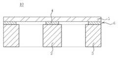
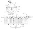
도 1 내지 도 3은 종래기술에 따른 관성센서의 제조방법을 공정순서대로 도시한 공정단면도이고, 이를 참조하여 종래기술의 문제점을 살펴본다.1 to 3 is a process cross-sectional view showing the manufacturing method of the inertial sensor according to the prior art in the process order, and looks at the problems of the prior art with reference to this.
우선, 도 1 내지 2에 도시된 바와 같이, SOI(Silicon On Insulator) 기판을 준비한 후, SOI 기판의 지지기판(1)을 선택적으로 제거하여 질량체(2)와 포스트(3)를 형성한다.First, as shown in FIGS. 1 and 2, after preparing a silicon on insulator (SOI) substrate, the
그후, 도 3에 도시된 바와 같이, 질량체(2)와 포스트(3) 사이에 에칭액을 공급하여 절연층(6; 산화실리콘)을 선택적으로 제거하여 접합층(4)을 형성한다. 이때, 접합층(4)의 면적은 멤브레인(5)의 스프링상수를 결정한다. 구체적으로, 접합층(4)의 면적이 좁아지면 실질적으로 탄성을 갖는 멤브레인(5)의 면적이 넓어져 스프링상수가 감소하고 그에 따라 관성센서(10)의 감도를 높일 수 있다. 따라서, 접합층(4)의 면적은 좁아질수록 바람직하지만, 질량체(2)와 포스트(3) 사이로 에칭액을 공급하여 접합층(4)을 제거하므로, 언더컷(Undercut) 현상을 고려한다고 하더라도 접합층(4)의 면적은 질량체(2)의 단면적의 영향을 받는다. 따라서, 접합층(4)의 면적을 좁히기 위해서는 질량체(2)의 단면적 역시 좁혀야 하지만, 이 경우 질량체(2)의 질량이 감소해 관성센서(10)의 감도가 떨어진다.Thereafter, as shown in FIG. 3, an etching solution is supplied between the
결국, 종래기술에 따른 관성센서(10)은 제조공정 상 질량체(2)의 질량을 증가시키면서 멤브레인(5)의 스프링상수를 감소시킬 수 없어 관성센서(10)의 감도를 향상시키는데 한계가 존재한다.
As a result, the
본 발명은 상기와 같은 문제점을 해결하기 위해 안출된 것으로서, 본 발명의 목적은 질량체에 상하방향으로 관통되도록 패터닝된 패터닝부를 채용하여 접합층의 면적을 좁힘으로써, 멤브레인의 스프링상수를 감소시켜 감도를 향상시킬 수 있는 관성센서 및 그 제조방법을 제공하기 위한 것이다.
The present invention has been made to solve the above problems, an object of the present invention is to reduce the spring constant of the membrane by reducing the spring constant of the membrane by employing a patterning portion patterned to penetrate in the vertical direction to the mass body, thereby reducing the sensitivity An object of the present invention is to provide an inertial sensor and a method of manufacturing the same.
본 발명의 바람직한 실시예에 따른 관성센서는 판상의 멤브레인, 상기 멤브레인의 중앙부분 하부에 배치되되, 중심부에 구비된 접합부 및 상기 접합부의 외측에 구비되어 상하방향으로 관통되도록 패터닝된 패터닝부를 포함하는 질량체 및 상기 멤브레인과 상기 접합부에 사이에 형성되되, 상기 패터닝부의 내측에 구비된 제1 접합층을 포함하여 구성된다.An inertial sensor according to a preferred embodiment of the present invention is a mass body including a plate-like membrane, disposed below the central portion of the membrane, the junction portion provided in the center and the patterning portion provided on the outer side of the junction portion and patterned to penetrate in the vertical direction. And a first bonding layer formed between the membrane and the bonding portion and provided inside the patterning portion.
여기서, 상기 제1 접합층은 상기 패터닝부를 마스크로 등방성 식각을 통해서 선택적으로 제거되어, 상기 제1 접합층은 상기 패터닝부의 내측에 구비된 것을 특징으로 한다.Here, the first bonding layer is selectively removed by isotropic etching with the patterning portion as a mask, the first bonding layer is characterized in that provided on the inside of the patterning portion.
또한, 상기 패터닝부는 다수의 홀이 형성되어 상하방향으로 관통되도록 패터닝된 것을 특징으로 한다.In addition, the patterning unit is characterized in that the plurality of holes are formed and patterned to penetrate in the vertical direction.
또한, 상기 패터닝부는 상기 접합부로부터 상기 접합부의 외측으로 연장된 다수의 제1 리브부가 형성되어 상하방향으로 관통되도록 패터닝된 것를 특징으로 한다.In addition, the patterning part is characterized in that the plurality of first ribs extending from the junction to the outside of the junction is formed to be patterned to penetrate in the vertical direction.
또한, 상기 패터닝부는 상기 접합부로부터 상기 접합부의 외측으로 연장된 다수의 제1 리브부 및 상기 제1 리브부의 측면으로부터 소정간격 마다 상기 접합부의 외측으로 연장된 다수의 제2 리브부가 형성되어 상하방향으로 관통되도록 패터닝된 것을 특징으로 한다.The patterning part may include a plurality of first rib parts extending from the joint part to the outside of the joint part and a plurality of second rib parts extending outward from the joint part at predetermined intervals from side surfaces of the first rib part, and are disposed in the vertical direction. It is characterized in that it is patterned to penetrate.
또한, 상기 질량체를 둘러싸도록 상기 멤브레인의 테두리 하부에 배치된 포스트 및 상기 멤브레인과 상기 포스트의 사이에 형성된 제2 접합층을 더 포함하는 것을 특징으로 한다.The apparatus may further include a post disposed under the edge of the membrane to surround the mass and a second bonding layer formed between the membrane and the post.
또한, 상기 포스트로부터 상기 질량체 방향으로 연장되되 상기 멤브레인의 하면과 소정간격 이격되어 형성된 지지부를 더 포함하는 것을 특징으로 한다.
The apparatus may further include a support extending from the post in the direction of the mass and spaced apart from the lower surface of the membrane by a predetermined distance.
본 발명의 바람직한 실시예에 따른 관성센서의 제조방법은 (A) 제1 기판, 제2 기판 및 멤브레인 순으로 적층된 베이스 부재를 준비하는 단계, (B) 상기 제1 기판의 중앙부분에 질량체가 형성되도록 상기 제1 기판을 패터닝하는 동시에, 중심부에 구비된 접합부 및 상기 접합부의 외측에 구비된 패터닝부를 포함하는 상기 질량체 중 상기 패터닝부를 상하방향으로 관통되도록 패터닝하는 단계 및 (C) 상기 패터닝부를 마스크로 등방성 식각을 통해서 상기 멤브레인과 상기 패터닝부 사이의 상기 제2 기판을 선택적으로 제거하여 상기 패터닝부의 내측에 잔존하는 상기 제2 기판으로 제1 접합층을 형성하는 단계를 포함하여 구성된다.In the method of manufacturing an inertial sensor according to a preferred embodiment of the present invention, (A) preparing a base member laminated in the order of the first substrate, the second substrate and the membrane, (B) a mass body in the central portion of the first substrate Patterning the first substrate so as to be formed, and patterning the patterning portion to penetrate the patterning portion vertically among the mass bodies including a bonding portion provided at a center portion and a patterning portion provided at an outer side of the bonding portion; and (C) masking the patterning portion. And selectively removing the second substrate between the membrane and the patterning portion through furnace isotropic etching to form a first bonding layer with the second substrate remaining inside the patterning portion.
여기서, 상기 (B) 단계에서, 다수의 홀을 형성하여 상기 패터닝부를 상하방향으로 관통되도록 패터닝하는 것을 특징으로 한다.Here, in the step (B), by forming a plurality of holes characterized in that the patterning to penetrate in the vertical direction.
또한, 상기 (B) 단계에서, 상기 접합부로부터 상기 접합부의 외측으로 연장된 다수의 제1 리브부를 형성하여 상기 패터닝부를 상하방향으로 관통되도록 패터닝하는 것을 특징으로 한다.In addition, in the step (B), a plurality of first ribs extending from the junction to the outside of the junction is formed by patterning the patterning portion to penetrate in the vertical direction.
또한, 상기 (B) 단계에서, 상기 접합부로부터 상기 접합부의 외측으로 연장된 다수의 제1 리브부 및 상기 제1 리브부의 측면으로부터 소정간격 마다 상기 접합부의 외측으로 연장된 다수의 제2 리브부를 형성하여 상기 패터닝부를 상하방향으로 관통되도록 패터닝하는 것을 특징으로 한다.In addition, in the step (B), a plurality of first rib portions extending from the junction portion to the outside of the junction portion and a plurality of second rib portions extending outside the junction portion at predetermined intervals from side surfaces of the first rib portion are formed. By patterning the patterning part to penetrate in the vertical direction.
또한, 상기 (B) 단계에서, 상기 제1 기판의 테두리에 상기 질량체를 둘러싸는 포스트가 형성되도록 상기 제1 기판을 패터닝하는 것을 특징으로 한다.In the step (B), the first substrate is patterned such that a post surrounding the mass body is formed at an edge of the first substrate.
또한, 상기 (C) 단계에서, 상기 질량체와 상기 포스트를 마스크로 등방성 식각을 통해서 상기 제2 기판을 선택적으로 제거하여 상기 멤브레인과 상기 포스트 사이에 잔존하는 상기 제2 기판으로 제2 접합층을 형성하는 것을 특징으로 한다.In the step (C), the second substrate is selectively removed by isotropic etching with the mass and the post as a mask to form a second bonding layer with the second substrate remaining between the membrane and the post. Characterized in that.
또한, 상기 (B) 단계에서, 비등방성 식각을 통해서 상기 제1 기판을 패터닝하는 동시에, 상기 패터닝부를 패터닝하는 것을 특징으로 한다.Further, in the step (B), the first substrate is patterned through anisotropic etching, and at the same time, the patterning unit is patterned.
또한, 상기 (B) 단계에서, 상기 포스트로부터 상기 질량체 방향으로 연장된 지지부가 형성되도록 상기 제1 기판을 패터닝하고, 상기 (C) 단계에서, 등방성 식각을 통해서 상기 멤브레인과 상기 지지부 사이의 상기 제2 기판을 제거하여 상기 멤브레인의 하면과 상기 지지부를 이격시키는 것을 특징으로 한다.
Further, in the step (B), the first substrate is patterned to form a support extending from the post in the direction of the mass, and in the step (C), the first portion between the membrane and the support isotropically etched through isotropic etching. 2, the lower surface of the membrane is separated from the support by removing the substrate.
본 발명의 특징 및 이점들은 첨부도면에 의거한 다음의 상세한 설명으로부터 더욱 명백해질 것이다.The features and advantages of the present invention will become more apparent from the following detailed description based on the accompanying drawings.
이에 앞서 본 명세서 및 청구범위에 사용된 용어나 단어는 통상적이고 사전적인 의미로 해석되어서는 아니되며, 발명자가 그 자신의 발명을 가장 최선의 방법으로 설명하기 위해 용어의 개념을 적절하게 정의할 수 있다는 원칙에 입각하여 본 발명의 기술적 사상에 부합되는 의미와 개념으로 해석되어야만 한다.
Prior to that, terms and words used in the present specification and claims should not be construed in a conventional and dictionary sense, and the inventor may properly define the concept of the term in order to best explain its invention It should be construed as meaning and concept consistent with the technical idea of the present invention.
본 발명에 따르면, 질량체에 상하방향으로 관통하도록 패터닝된 패터닝부를 채용하고, 상기 패터닝부를 마스크로 등방성 식각을 통해서 접합층의 면적을 좁힘으로써, 멤브레인의 스프링상수를 감소시켜 관성센서의 감도를 향상시킬 수 있는 효과가 있다.
According to the present invention, by patterning the patterned portion to penetrate in the vertical direction to the mass body, and by narrowing the area of the bonding layer through the isotropic etching with the patterned portion as a mask, the spring constant of the membrane is reduced to improve the sensitivity of the inertial sensor It can be effective.
또한, 본 발명에 따르면, 패터닝부를 이용하여 제1 접합층의 면적을 자유롭게 제어할 수 있으므로, 질량체의 단면적을 넓게 설계할 수 있어 질량체의 질량을 증가시킬 수 있고, 그에 따라 관성센서의 감도를 향상시킬 수 있는 장점이 있다.
In addition, according to the present invention, since the area of the first bonding layer can be freely controlled by using the patterning unit, the cross-sectional area of the mass can be designed to increase the mass of the mass, thereby improving the sensitivity of the inertial sensor. There is an advantage to this.
또한, 본 발명에 따르면, 질량체에 상하방향으로 관통하도록 패터닝된 패터닝부를 형성하여 진동시 공기의 점성으로 인한 감쇠력을 저감시킴으로써, 질량체의 변위가 증가되어 관성센서의 감도를 높일 수 있는 효과가 있다.
In addition, according to the present invention, by forming a patterning portion patterned to penetrate the mass in the vertical direction to reduce the damping force due to the viscosity of the air during vibration, the displacement of the mass is increased, thereby increasing the sensitivity of the inertial sensor.
도 1 내지 도 3은 종래기술에 따른 관성센서의 제조방법을 공정순서대로 도시한 공정단면도;
도 4는 본 발명의 바람직한 실시예에 따른 관성센서의 단면도;
도 5는 본 발명의 바람직한 실시예에 따른 관성센서의 질량체 및 포스트의 평면도;
도 6 내지 도 7은 도 5에 도시된 질량체 및 포스트의 변형예를 도시한 평면도;
도 8은 본 발명의 바람직한 실시예에 따른 관성센서의 변형예를 도시한 단면도;
도 9는 도 8에 도시된 관성센서의 하방 변위를 제한하는 과정을 도시한 단면도;
도 10은 도 8에 도시된 관성센서의 질량체, 포스트 및 지지부의 평면도; 및
도 11 내지 도 14는 본 발명의 바람직한 실시예에 따른 관성센서의 제조방법을 공정순서대로 도시한 공정단면도이다.1 to 3 is a process cross-sectional view showing the manufacturing method of the inertial sensor according to the prior art in the process order;
4 is a sectional view of an inertial sensor according to a preferred embodiment of the present invention;
5 is a plan view of a mass and a post of an inertial sensor according to a preferred embodiment of the present invention;
6 to 7 are plan views showing modifications of the mass and the post shown in FIG. 5;
8 is a sectional view showing a modification of the inertial sensor according to a preferred embodiment of the present invention;
9 is a cross-sectional view showing a process of limiting the downward displacement of the inertial sensor shown in FIG. 8;
10 is a plan view of a mass, a post and a support of the inertial sensor shown in FIG. 8; And
11 to 14 are process cross-sectional views showing the manufacturing method of the inertial sensor according to the preferred embodiment of the present invention in the order of process.
본 발명의 목적, 특정한 장점들 및 신규한 특징들은 첨부된 도면들과 연관되어지는 이하의 상세한 설명과 바람직한 실시예들로부터 더욱 명백해질 것이다. 본 명세서에서 각 도면의 구성요소들에 참조번호를 부가함에 있어서, 동일한 구성 요소들에 한해서는 비록 다른 도면상에 표시되더라도 가능한 한 동일한 번호를 가지도록 하고 있음에 유의하여야 한다. 또한, "제1", "제2" 등의 용어는 하나의 구성요소를 다른 구성요소로부터 구별하기 위해 사용되는 것으로, 구성요소가 상기 용어들에 의해 제한되는 것은 아니다. 그리고, 본 발명을 설명함에 있어서, 본 발명의 요지를 불필요하게 흐릴 수 있는 관련된 공지 기술에 대한 상세한 설명은 생략하도록 한다.
BRIEF DESCRIPTION OF THE DRAWINGS The objectives, specific advantages and novel features of the present invention will become more apparent from the following detailed description taken in conjunction with the accompanying drawings, in which: FIG. It should be noted that, in the present specification, the reference numerals are added to the constituent elements of the drawings, and the same constituent elements are assigned the same number as much as possible even if they are displayed on different drawings. In addition, terms such as “first” and “second” are used to distinguish one component from another component, and the component is not limited by the terms. In the following description of the present invention, a detailed description of related arts which may unnecessarily obscure the gist of the present invention will be omitted.
이하, 첨부된 도면을 참조하여 본 발명의 바람직한 실시예를 상세히 설명하기로 한다.
Hereinafter, preferred embodiments of the present invention will be described in detail with reference to the accompanying drawings.
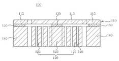
도 4는 본 발명의 바람직한 실시예에 따른 관성센서의 단면도이고, 도 5는 본 발명의 바람직한 실시예에 따른 관성센서의 질량체 및 포스트의 평면도이며, 도 6 내지 도 7은 도 5에 도시된 질량체 및 포스트의 변형예를 도시한 평면도이다.
4 is a cross-sectional view of an inertial sensor according to a preferred embodiment of the present invention, FIG. 5 is a plan view of a mass body and a post of an inertial sensor according to a preferred embodiment of the present invention, and FIGS. 6 to 7 are mass bodies shown in FIG. And a plan view showing a modification of the post.
도 4 내지 도 5에 도시된 바와 같이, 본 실시예에 따른 관성센서(100)는 판상의 멤브레인(110), 멤브레인(110)의 중앙부분(113) 하부에 배치되되, 중심부에 구비된 접합부(123) 및 접합부(123)의 외측에 구비되어 상하방향으로 관통되도록 패터닝된 패터닝부(125)를 포함하는 질량체(120) 및 멤브레인(110)과 접합부(123)에 사이에 형성되되, 패터닝부(125)의 내측에 구비된 제1 접합층(130)을 포함하는 구성이다.
4 to 5, the
상기 멤브레인(110)은 판상으로 형성되어 질량체(120)가 진동할 수 있도록 탄성을 갖는다. 여기서, 멤브레인(110)의 경계는 정확히 구획되는 것은 아니지만, 멤브레인(110)의 중앙에 구비된 중앙부분(113)과 멤브레인(110)의 외곽을 따라 구비된 테두리(115)로 구획될 수 있다. 이때, 멤브레인(110)의 중앙부분(113) 하부에는 질량체(120)가 배치되므로, 멤브레인(110)의 중앙부분(113)은 질량체(120)의 움직임에 대응하는 변위가 발생한다. 또한, 멤브레인(110)의 테두리(115) 하부에는 포스트(140)가 배치되어, 멤브레인(110)의 중앙부분(113)을 지지하는 역할을 수행한다. 한편, 멤브레인(110)에는 PZT(Lead Zirconate Titanate) 등의 압전체와 전극이 형성되어 압전효과를 이용하여 질량체(120)의 변위를 감지하거나 역압전효과를 이용하여 질량체(120)를 진동시킬 수 있다. 다만, 본 실시예에 따른 관성센서(100)는 반드시 압전체를 이용하는 압전방식이어야 하는 것은 아니고, 압저항방식이나 정전용량방식 등 당업계에 공지된 모든 구동방식 또는 감지방식일 수 있다.
The
상기 질량체(120)는 관성력이나 코리올리힘에 의해서 변위가 발생하는 것으로, 멤브레인(110)의 중앙부분(113) 하부에 배치된다. 구체적으로, 질량체(120)는 중심부에 구비된 접합부(123)와 접합부(123)의 외측에 구비된 패터닝부(125)로 구획된다. 여기서, 접합부(123)는 제1 접합층(130)으로 멤브레인(110)의 하면에 부착되는 부분이다. 또한, 패터닝부(125)는 상하방향(판상의 멤브레인(110)에 대해 수직방향)으로 관통되도록 패터닝된 부분으로, 패터닝부(125)와 멤브레인(110)의 하면 사이에는 제1 접합층(130)이 존재하지 않는다. 패터닝부(125)와 멤브레인(110) 사이에 제1 접합층(130)이 존재하지 않는 이유는 제조공정 중 패터닝부(125)를 마스크로 등방성 식각을 통해서 제1 접합층(130)을 선택적으로 제거하기 때문이다. 전술한 바와 같이, 질량체(120) 중 접합부(123)만이 제1 접합층(130)에 의해서 멤브레인(110)의 하면에 부착되고, 패터닝부(125)는 멤브레인(110)의 하면에 부착되지 않는다. 따라서, 종래기술에 따른 관성센서와 비교할 때, 제1 접합층(130)의 면적을 좁힐 수 있어 상대적으로 멤브레인(110)의 스프링상수를 감소시킬 수 있다. 또한, 패터닝부(125)를 이용하여 제1 접합층(130)의 면적을 자유롭게 제어할 수 있으므로, 질량체(120)의 단면적을 넓게 설계할 수 있어 질량체(120)의 질량을 증가시킬 수 있다. 이와 같이, 본 실시예에 따른 관성센서(100)는 멤브레인(110)의 스프링상수를 감소시킬 수 있고, 질량체(120)의 질량을 증가시킬 수 있으므로, 최종적으로는 동일한 가속도 또는 각속도에 대하여 질량체(120)의 변위를 증가시킬 수 있어 감도를 향상시킬 수 있다.The
한편, 질량체(120)의 패터닝부(125)의 형상은 마스크로 이용할 수 있도록 상하방향을 관통하는 구성이면 특별히 한정되지 않는다. 다만, 패터닝부(125)를 마스크로 등방성 식각을 통해서 제1 접합층(130)을 균등하게 제거하기 위해서, 패터닝부(125)는 다수의 홀(126)을 형성하여 패터닝하는 것이 바람직하고, 더욱 바람직하게는 다수의 홀(126)을 일정간격(△P)으로 형성한다(도 5 참조). 이외에도, 패터닝부(125)는 도 6 내지 도 7에 도시된 바와 같이, 리브(rib)부(127, 128)가 형성되도록 패터닝할 수 있다. 구체적으로, 패터닝부(125)는 접합부(123)로부터 접합부(123)의 외측으로 연장된 다수의 제1 리브부(127)가 형성되도록 패터닝할 수 있다(도 6 참조). 또는, 상기 제1 리브부(127)와 제1 리브부(127)의 측면으로부터 소정간격 마다 접합부(123)의 외측으로 연장된 다수의 제2 리브부(128)가 형성되도록 패터닝할 수 있다(도 7 참조). 즉, 패터닝부(125)에 접합부(123)의 외측 방향으로 다수의 슬릿(129)을 가공함으로써, 상기 제1 리브부(127) 또는 제2 리브부(128)가 형성되도록 패터닝할 수 있는 것이다. 한편, 패터닝부(125)에 다수의 슬릿(129)을 가공하고, 상기 슬릿(129) 사이로 지지부(160)를 배치할 수 있는데(도 10 참조), 이에 관한 구체적인 설명은 후술하도록 한다.In addition, the shape of the
전술한 바와 같이, 질량체(120)의 패터닝부(125)는 상하방향으로 관통되어 공기의 소통이 자유로우므로, 진동시 공기의 점성으로 인한 감쇠력이 저감되고, 그에 따라 질량체(120)의 변위가 증가되어 관성센서(100)의 감도를 높일 수 있는 효과가 있다.
As described above, since the
도 4에 도시된 바와 같이, 상기 제1 접합층(130)은 멤브레인(110)과 접합부(123) 사이에 형성되어 질량체(120)를 멤브레인(110)에 접합시키는 역할을 한다. 전술한 바와 같이, 제1 접합층(130)은 제조공정 중 패터닝부(125)를 마스크로 이용한 등방성 식각을 통해서 제거되므로, 패터닝부(125)의 내측에만 구비된다.
As shown in FIG. 4, the
한편, 멤브레인(110)의 테두리(115) 하부에는 멤브레인(110)의 지지하는 포스트(140)가 배치된다. 여기서, 포스트(140)는 질량체(120)가 변위를 일으킬 수 있는 공간을 확보하도록 질량체(120)를 둘러싸는 중공(中空)형으로 형성된다. 예를 들어, 포스트(140)는 중심에 공동(空洞)이 형성된 사각기둥 형상으로 형성될 수 있다(도 5 참조). 한편, 멤브레인(110)과 포스트(140) 사이에는 제2 접합층(150)이 형성되어, 포스트(140)는 제2 접합층(150)에 의해서 멤브레인(110)의 하면에 접합된다(도 4 참조).
Meanwhile, a
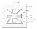
또한, 도 8은 본 발명의 바람직한 실시예에 따른 관성센서의 변형예를 도시한 단면도이고, 도 9는 도 8에 도시된 관성센서의 하방 변위를 제한하는 과정을 도시한 단면도이며, 도 10은 도 8에 도시된 관성센서의 질량체, 포스트 및 지지부의 평면도이다.In addition, Figure 8 is a cross-sectional view showing a modification of the inertial sensor according to a preferred embodiment of the present invention, Figure 9 is a cross-sectional view showing a process of limiting the downward displacement of the inertial sensor shown in Figure 8, Figure 10 8 is a plan view of a mass, a post, and a support of the inertial sensor shown in FIG. 8.
도 8 내지 도 10에 도시된 바와 같이, 본 실시예에 따른 관성센서(100)는 질량체(120)의 하방 변위를 제한하는 역할을 수행하는 지지부(160)를 더 포함할 수 있다. 여기서, 지지부(160)는 포스트(140)의 내측면을 따라 소정간격으로 4개가 핀 형상으로 형성되어 질량체(120) 방향으로 연장될 수 있다(도 10 참조). 다만, 지지부(160)는 반드시 4개가 구비되어야 하는 것은 아니고, 포스트(140)의 내측면을 따라 등간격으로 2개 이상 형성될 수도 있다. 즉, 지지부(160)는 포스트(140)의 내측면을 따라 180도 간격으로 2개가 형성되거나, 120도 간격으로 3개가 형성될 수 있는 것이다. 한편, 패터닝부(125)에 다수의 슬릿(129)을 가공한 경우, 핀 형상의 지지부(160)는 상기 슬릿(129) 사이를 따라 질량체(120)의 접합부(123) 직전까지 연장될 수 있다. 따라서, 질량체(120)의 크기를 유지하면서도 지지부(160)의 길이를 자유롭게 조절할 수 있어 질량체(120)의 하방 변위를 제한하기 용이하고 관성센서(100)의 내부 공간을 효율적으로 활용할 수 있다. 또한, 지지부(160)는 멤브레인(110)의 하면과 소정간격(D) 이격되도록 배치된다(도 8 참조). 상기 소정간격(D)은 질량체(120)의 하방변위를 제한하는 기준으로, 허용치를 초과하는 과도한 힘이 질량체(120)에 작용하더라도 질량체(120)의 하측 방향 변위는 지지부(160)와 멤브레인(110) 사이의 소정간격(D)으로 제한된다(도 9 참조).
As shown in FIGS. 8 to 10, the
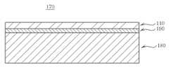
도 11 내지 도 14는 본 발명의 바람직한 실시예에 따른 관성센서의 제조방법을 공정순서대로 도시한 공정단면도이다.11 to 14 are process cross-sectional views showing the manufacturing method of the inertial sensor according to the preferred embodiment of the present invention in the order of process.
도 11 내지 도 14에 도시된 바와 같이, 본 실시예에 따른 관성센서(100)는 (A) 제1 기판(180), 제2 기판(190) 및 멤브레인(110) 순으로 적층된 베이스 부재(170)를 준비하는 단계, (B) 제1 기판(180)의 중앙부분(183)에 질량체(120)가 형성되도록 제1 기판(180)을 패터닝하는 동시에, 중심부에 구비된 접합부(123) 및 접합부(123)의 외측에 구비된 패터닝부(125)를 포함하는 질량체(120) 중 패터닝부(125)를 상하방향으로 관통되도록 패터닝하는 단계 및 (C) 패터닝부(125)를 마스크로 등방성 식각을 통해서 멤브레인(110)과 패터닝부(125) 사이의 제2 기판(190)을 선택적으로 제거하여 패터닝부(125)의 내측에 잔존하는 제2 기판(190)으로 제1 접합층(130)을 형성하는 단계를 포함하는 구성이다.
11 to 14, the
우선, 도 11에 도시된 바와 같이, 제1 기판(180), 제2 기판(190) 및 멤브레인(110) 순으로 적층된 베이스 부재(170)를 준비하는 단계이다. 여기서, 베이스 부재(170)의 재질은 특별히 한정되는 것은 아니지만, MEMS(Micro Electro Mechanical Systems) 공정이 용이한 SOI(Silicon On Insulator) 기판을 이용하는 것이 바람직하다. 이 경우, 제1 기판(180)이 SOI기판의 지지기판이 되고, 제2 기판(190)이 SOI기판의 절연층(산화실리콘)이 되며, 멤브레인(110)이 SOI기판의 상부실리콘층이 된다.
First, as shown in FIG. 11, a step of preparing the
다음, 도 12 내지 도 13에 도시된 바와 같이, 제1 기판(180)을 패터닝하여 질량체(120)를 형성하는 동시에, 질량체(120)의 패터닝부(125)를 상하방향으로 관통되도록 패터닝하는 단계이다. 구체적으로, 제1 기판(180) 중 중앙부분(183)에 질량체(120)가 형성되어야 한다. 또한, 질량체(120)는 중심부에 구비된 접합부(123)와 접합부(123)의 외측에 구비된 패터닝부(125)로 구획되는데, 상기 패터닝부(125)는 상하방향으로 관통되어야 한다. 따라서, 질량체(120)와 패터닝부(125)의 형상에 대응하는 마스크(187)를 제1 기판(180)에 배치한 후(도 12 참조), 식각 공정을 통해서 제1 기판(180)을 선택적으로 제거한다(도 13 참조). 이때, 식각 공정은 멤브레인(110)의 수직방향으로 제1 기판(180)이 제거되도록 비등방성 식각을 이용하는 것이 바람직하다. 상기 비등방성 식각은 특별히 한정되는 것은 아니지만, 건식 식각인 것이 바람직하고, 더욱 바람직하게는 DRIE(Deep Reactive Ion Etching)를 이용할 수 있다. DRIE는 플라즈마에 의해 형성된 이온의 물리적 충돌과 화학적 반응을 동시에 진행시켜 식각을 수행하는 공정이다. 특히, DRIE는 정밀하게 제1 기판(180)을 제거할 수 있을 뿐 만 아니라, 물질에 따른 선택적 에칭이 가능하므로 제1 기판(180)과 마스크(187) 중 정확히 제1 기판(180)만 식각할 수 있는 장점이 있다.Next, as shown in FIGS. 12 to 13, the
이때, 상기 패터닝부(125)에는 다수의 홀(126)을 형성하거나(도 5 참조), 접합부(123)로부터 접합부(123)의 외측으로 연장된 다수의 제1 리브부(127)를 형성하거나(도 6 참조), 제1 리브부(127)에 추가적으로 제1 리브부(127)의 측면으로부터 소정간격 마다 접합부(123)의 외측으로 연장된 다수의 제2 리브부(128)를 형성할 수 있다(도 7 참조).In this case, a plurality of
한편, 제1 기판(180)을 패터닝하여 제1 기판(180)의 중앙부분(183)에 질량체(120)를 형성하는 동시에, 제1 기판(180)의 테두리(185)에 질량체(120)를 둘러싸는 포스트(140)를 형성할 수 있다. 또한, 질량체(120) 및 포스트(140)와 동시에, 제1 기판(180)을 패터닝하여 포스트(140)로부터 질량체(120) 방향으로 연장된 지지부(160)가 형성할 수 있다(도 8 참조). 구체적으로, 하나의 마스크(187)에 질량체(120), 포스트(140) 및 지지부(160)의 형상에 대응하는 마스크(187)를 제1 기판(180)에 배치한 후, 식각 공정을 통해서 제1 기판(180)을 선택적으로 제거하면, 질량체(120), 포스트(140) 및 지지부(160)를 동시에 형성할 수 있다.
Meanwhile, the
다음, 도 14에 도시된 바와 같이, 패터닝부(125)를 마스크로 등방성 식각을 통해서 멤브레인(110)과 패터닝부(125) 사이의 제2 기판(190)을 선택적으로 제거하여 패터닝부(125)의 내측에 잔존하는 제2 기판(190)으로 제1 접합층(130)을 형성하는 단계이다. 이전 단계에서 패터닝부(125)를 상하방향으로 관통되도록 패터닝하였으므로, 본 단계에서 패터닝부(125)를 마스크로 등방성 식각을 수행할 수 있다. 등방성 식각을 통해서 제2 기판(190)을 제거하므로, 제2 기판(190)은 두께 방향뿐만 아니라 평면 방향으로도 제거되는 언더컷(Undercut) 현상이 발생한다. 따라서, 패터닝부(125)와 멤브레인(110) 사이의 제2 기판(190)을 모두 제거할 수 있고, 최종적으로 패터닝부(125)의 내측에만 잔존하는 제2 기판(190)으로 제1 접합층(130)을 형성할 수 있다. 다만, 패터닝부(125)와 멤브레인(110) 사이의 제2 기판(190)을 완전히 제거하기 위해서는, 제2 기판(190) 중 홀(126) 사이에 대응하는 소정부분(R; 도 14의 확대도 참조)이 제거되어야 한다. 그런데, 상기 소정부분(R)은 인접한 두 홀(126)로부터 언더컷 현상이 발생하여 평면 방향으로 일정한 깊이(△E)가 제거된다. 따라서, 등방성 식각이 제2 기판(190)을 평면 방향으로 제거하는 깊이(△E)가 패터닝부(125)의 홀(126) 간격(△P)의 1/2보다 커야 패터닝부(125)와 멤브레인(110) 사이의 제2 기판(190)을 완전히 제거할 수 있다(△E>△P/2). 다만, 도 5의 확대도에 도시된 바와 같이, 상술한 내용은 최단 간격(△P)으로 인접한 두 홀(126)을 기준으로 설명한 것이고, 대각선상으로 인접한 두 홀(126)을 기준으로 설명한다면, 등방성 식각이 제2 기판(190)을 제거하는 깊이(△E)는 패터닝부(125)의 홀(126) 간격(△P)의 √2×1/2보다 커야 한다.Next, as shown in FIG. 14, the
또한, 패터닝부(125)에 홀(126)을 형성한 것을 기준으로 설명하였지만, 제1 리브부(127) 또는 제2 리브부(128)를 형성한 경우에도 등방성 식각이 제2 기판(190)을 평면 방향으로 제거하는 깊이(△E)가 패터닝부(125)의 슬릿(129) 간격(△P; 도 6 내지 도 7 참조)의 1/2보다 큰 것이 바람직하다. 한편, 상기 등방성 식각은 특별히 한정되는 것은 아니지만, 에칭액을 이용하는 습식 식각을 이용하는 것이 바람직하고, 에칭액으로는 HF수용액을 이용할 수 있다.In addition, although the
전술한 바와 같이, 멤브레인(110)과 패터닝부(125) 사이의 제2 기판(190)을 제거하여 제1 접합층(130)을 형성하므로, 제1 접합층(130)의 면적을 좁힐 수 있어 상대적으로 멤브레인(110)의 스프링상수를 감소시킴으로써 관성센서(100)의 감도를 향상시킬 수 있다.
As described above, since the
한편, 이전 단계에서 제1 기판(180)을 패터닝하여 포스트(140)를 형성한 경우, 본 단계에서 질량체(120)와 포스트(140)를 마스크로 등방성 식각을 통해서 제2 기판(190)을 선택적으로 제거하여 멤브레인(110)과 포스트(140) 사이에 잔존하는 제2 기판(190)으로 제2 접합층(150)을 형성할 수 있다.Meanwhile, when the
그리고, 이전 단계에서 제1 기판(180)을 패터닝하여 지지부(160)를 형성한 경우, 본 단계에서 등방성 식각을 통해서 멤브레인(110)과 지지부(160) 사이의 제2 기판(190)을 제거하여 멤브레인(110)의 하면과 지지부(160)를 이격시킬 수 있다(도 8 참조).
In the previous step, when the
이상 본 발명을 구체적인 실시예를 통하여 상세히 설명하였으나, 이는 본 발명을 구체적으로 설명하기 위한 것으로, 본 발명에 따른 관성센서 및 그 제조방법은 이에 한정되지 않으며, 본 발명의 기술적 사상 내에서 당해 분야의 통상의 지식을 가진 자에 의해 그 변형이나 개량이 가능함은 명백하다고 할 것이다. 본 발명의 단순한 변형 내지 변경은 모두 본 발명의 영역에 속하는 것으로 본 발명의 구체적인 보호 범위는 첨부된 특허청구범위에 의하여 명확해질 것이다.
Although the present invention has been described in detail through specific embodiments, this is for explaining the present invention in detail, and an inertial sensor and a method of manufacturing the same according to the present invention are not limited thereto. It will be apparent that modifications and improvements are possible by those skilled in the art. It will be understood by those skilled in the art that various changes in form and details may be made therein without departing from the spirit and scope of the invention as defined by the appended claims.
100: 관성센서110: 멤브레인
113: 멤브레인의 중앙부분115: 멤브레인의 테두리
120: 질량체123: 접합부
125: 패터닝부126: 홀
127: 제1 리브부128: 제2 리브부
129: 슬릿130: 제1 접합층
140: 포스트150: 제2 접합층
160: 지지부170: 베이스 부재
180: 제1 기판183: 제1 기판의 중앙부분
185: 제1 기판의 테두리187: 마스크
190: 제2 기판D: 소정간격
R: 소정부분△E: 평면 방향으로 제거되는 깊이
△P: 홀/슬릿 간격100: inertial sensor 110: membrane
113: central portion of the membrane 115: membrane edge
120: mass 123: junction
125: patterning portion 126: hole
127: first rib portion 128: second rib portion
129: slit 130: first bonding layer
140: post 150: second bonding layer
160: support 170: base member
180: first substrate 183: central portion of the first substrate
185: Border of the first substrate 187: Mask
190: second substrate D: predetermined interval
R: predetermined portion ΔE: depth removed in the planar direction
ΔP: Hole / Slit Spacing
Claims (15)
Translated fromKorean상기 멤브레인의 중앙부분 하부에 배치되되, 중심부에 구비된 접합부 및 상기 접합부의 외측에 구비되어 상하방향으로 관통되도록 패터닝된 패터닝부를 포함하는 질량체; 및
상기 멤브레인과 상기 접합부에 사이에 형성되되, 상기 패터닝부의 내측에 구비된 제1 접합층;
을 포함하는 것을 특징으로 하는 관성센서.
Plate-like membranes;
A mass body disposed below the central portion of the membrane and including a junction portion provided at a center portion and a patterning portion provided outside the junction portion and patterned to penetrate upward and downward; And
A first bonding layer formed between the membrane and the bonding portion and provided inside the patterning portion;
An inertial sensor comprising a.
상기 제1 접합층은 상기 패터닝부를 마스크로 등방성 식각을 통해서 선택적으로 제거되어, 상기 제1 접합층은 상기 패터닝부의 내측에 구비된 것을 특징으로 하는 관성센서.
The method according to claim 1,
And the first bonding layer is selectively removed through isotropic etching with the patterning unit as a mask, and the first bonding layer is provided inside the patterning unit.
상기 패터닝부는 다수의 홀이 형성되어 상하방향으로 관통되도록 패터닝된 것을 특징으로 하는 관성센서.
The method according to claim 1,
The patterning unit is an inertial sensor characterized in that a plurality of holes are formed and patterned to penetrate in the vertical direction.
상기 패터닝부는 상기 접합부로부터 상기 접합부의 외측으로 연장된 다수의 제1 리브부가 형성되어 상하방향으로 관통되도록 패터닝된 것를 특징으로 하는 관성센서.
The method according to claim 1,
The patterning unit is an inertial sensor characterized in that the plurality of first ribs extending from the junction to the outside of the junction is formed to penetrate in the vertical direction.
상기 패터닝부는 상기 접합부로부터 상기 접합부의 외측으로 연장된 다수의 제1 리브부 및 상기 제1 리브부의 측면으로부터 소정간격 마다 상기 접합부의 외측으로 연장된 다수의 제2 리브부가 형성되어 상하방향으로 관통되도록 패터닝된 것을 특징으로 하는 관성센서.
The method according to claim 1,
The patterning part may include a plurality of first rib parts extending from the joint part to the outside of the joint part and a plurality of second rib parts extending out of the joint part at predetermined intervals from side surfaces of the first rib part to penetrate in the vertical direction. Inertial sensor characterized in that the patterned.
상기 질량체를 둘러싸도록 상기 멤브레인의 테두리 하부에 배치된 포스트; 및
상기 멤브레인과 상기 포스트의 사이에 형성된 제2 접합층;
을 더 포함하는 것을 특징으로 하는 관성센서.
The method according to claim 1,
A post disposed below the edge of the membrane to surround the mass; And
A second bonding layer formed between the membrane and the post;
Inertial sensor, characterized in that it further comprises.
상기 포스트로부터 상기 질량체 방향으로 연장되되 상기 멤브레인의 하면과 소정간격 이격되어 형성된 지지부를 더 포함하는 것을 특징으로 하는 관성센서.
The method of claim 6,
And a support portion extending from the post in the direction of the mass and spaced apart from the lower surface of the membrane by a predetermined distance.
(B) 상기 제1 기판의 중앙부분에 질량체가 형성되도록 상기 제1 기판을 패터닝하는 동시에, 중심부에 구비된 접합부 및 상기 접합부의 외측에 구비된 패터닝부를 포함하는 상기 질량체 중 상기 패터닝부를 상하방향으로 관통되도록 패터닝하는 단계; 및
(C) 상기 패터닝부를 마스크로 등방성 식각을 통해서 상기 멤브레인과 상기 패터닝부 사이의 상기 제2 기판을 선택적으로 제거하여 상기 패터닝부의 내측에 잔존하는 상기 제2 기판으로 제1 접합층을 형성하는 단계;
를 포함하는 것을 특징으로 하는 관성센서의 제조방법.
(A) preparing a base member laminated in the order of the first substrate, the second substrate and the membrane;
(B) patterning the first substrate such that a mass is formed in a central portion of the first substrate, and at the same time, the patterning part of the mass including a bonding portion provided at a central portion and a patterning portion provided at an outer side of the bonding portion in a vertical direction; Patterning to penetrate; And
(C) selectively removing the second substrate between the membrane and the patterning portion through isotropic etching with the patterning portion as a mask to form a first bonding layer with the second substrate remaining inside the patterning portion;
Method of manufacturing an inertial sensor comprising a.
상기 (B) 단계에서,
다수의 홀을 형성하여 상기 패터닝부를 상하방향으로 관통되도록 패터닝하는 것을 특징으로 하는 관성센서의 제조방법.
The method according to claim 8,
In the step (B)
Forming a plurality of holes to pattern the patterning portion to penetrate in the vertical direction.
상기 (B) 단계에서,
상기 접합부로부터 상기 접합부의 외측으로 연장된 다수의 제1 리브부를 형성하여 상기 패터닝부를 상하방향으로 관통되도록 패터닝하는 것을 특징으로 하는 관성센서의 제조방법.
The method according to claim 8,
In the step (B)
And forming a plurality of first ribs extending from the junction to the outside of the junction to pattern the patterning portion so as to penetrate in the vertical direction.
상기 (B) 단계에서,
상기 접합부로부터 상기 접합부의 외측으로 연장된 다수의 제1 리브부 및 상기 제1 리브부의 측면으로부터 소정간격 마다 상기 접합부의 외측으로 연장된 다수의 제2 리브부를 형성하여 상기 패터닝부를 상하방향으로 관통되도록 패터닝하는 것을 특징으로 하는 관성센서의 제조방법.
The method according to claim 8,
In the step (B)
A plurality of first rib portions extending from the junction portion to the outside of the junction portion and a plurality of second rib portions extending outwardly of the junction portion at predetermined intervals from side surfaces of the first rib portion so as to penetrate the patterning portion in a vertical direction; Method of manufacturing an inertial sensor characterized in that the patterning.
상기 (B) 단계에서,
상기 제1 기판의 테두리에 상기 질량체를 둘러싸는 포스트가 형성되도록 상기 제1 기판을 패터닝하는 것을 특징으로 하는 관성센서의 제조방법.
The method according to claim 8,
In the step (B)
And patterning the first substrate such that a post surrounding the mass is formed at an edge of the first substrate.
상기 (C) 단계에서,
상기 질량체와 상기 포스트를 마스크로 등방성 식각을 통해서 상기 제2 기판을 선택적으로 제거하여 상기 멤브레인과 상기 포스트 사이에 잔존하는 상기 제2 기판으로 제2 접합층을 형성하는 것을 특징으로 하는 관성센서의 제조방법.
The method of claim 12,
In the step (C),
The second substrate is selectively formed by isotropic etching with the mass and the post as a mask to form a second bonding layer with the second substrate remaining between the membrane and the post. Way.
상기 (B) 단계에서,
비등방성 식각을 통해서 상기 제1 기판을 패터닝하는 동시에, 상기 패터닝부를 패터닝하는 것을 특징으로 하는 관성센서의 제조방법.
The method according to claim 8,
In the step (B)
And patterning the patterned portion at the same time as patterning the first substrate through anisotropic etching.
상기 (B) 단계에서,
상기 포스트로부터 상기 질량체 방향으로 연장된 지지부가 형성되도록 상기 제1 기판을 패터닝하고,
상기 (C) 단계에서,
등방성 식각을 통해서 상기 멤브레인과 상기 지지부 사이의 상기 제2 기판을 제거하여 상기 멤브레인의 하면과 상기 지지부를 이격시키는 것을 특징으로 하는 관성센서의 제조방법.The method of claim 12,
In the step (B)
Patterning the first substrate to form a support extending from the post in the direction of the mass body,
In the step (C),
And removing the second substrate between the membrane and the support part by isotropic etching to space the lower surface of the membrane from the support part.
Priority Applications (3)
| Application Number | Priority Date | Filing Date | Title |
|---|---|---|---|
| KR1020110050200AKR20120131788A (en) | 2011-05-26 | 2011-05-26 | Inertial Sensor And Method of Manufacturing The Same |
| US13/177,485US8887569B2 (en) | 2010-05-26 | 2011-07-06 | Inertial sensor and method of manufacturing the same |
| US14/514,356US9919917B2 (en) | 2011-05-26 | 2014-10-14 | Inertial sensor and method of manufacturing the same |
Applications Claiming Priority (1)
| Application Number | Priority Date | Filing Date | Title |
|---|---|---|---|
| KR1020110050200AKR20120131788A (en) | 2011-05-26 | 2011-05-26 | Inertial Sensor And Method of Manufacturing The Same |
Publications (1)
| Publication Number | Publication Date |
|---|---|
| KR20120131788Atrue KR20120131788A (en) | 2012-12-05 |
Family
ID=45020961
Family Applications (1)
| Application Number | Title | Priority Date | Filing Date |
|---|---|---|---|
| KR1020110050200AWithdrawnKR20120131788A (en) | 2010-05-26 | 2011-05-26 | Inertial Sensor And Method of Manufacturing The Same |
Country Status (2)
| Country | Link |
|---|---|
| US (2) | US8887569B2 (en) |
| KR (1) | KR20120131788A (en) |
Families Citing this family (2)
| Publication number | Priority date | Publication date | Assignee | Title |
|---|---|---|---|---|
| KR101194536B1 (en)* | 2011-04-20 | 2012-10-24 | 삼성전기주식회사 | Method of manufacturing inertial sensor |
| US20190110132A1 (en)* | 2015-09-18 | 2019-04-11 | Vesper Technologies Inc. | Plate Spring |
Family Cites Families (8)
| Publication number | Priority date | Publication date | Assignee | Title |
|---|---|---|---|---|
| FR2700065B1 (en)* | 1992-12-28 | 1995-02-10 | Commissariat Energie Atomique | Method of manufacturing accelerometers using silicon on insulator technology. |
| JP4216525B2 (en)* | 2002-05-13 | 2009-01-28 | 株式会社ワコー | Acceleration sensor and manufacturing method thereof |
| JP4272115B2 (en)* | 2004-06-03 | 2009-06-03 | Okiセミコンダクタ株式会社 | Acceleration sensor and manufacturing method thereof |
| JP4540467B2 (en)* | 2004-12-22 | 2010-09-08 | Okiセミコンダクタ株式会社 | Structure of acceleration sensor and manufacturing method thereof |
| JP2007248147A (en)* | 2006-03-14 | 2007-09-27 | Oki Electric Ind Co Ltd | Structure of acceleration sensor and its manufacturing method |
| US7845229B2 (en)* | 2006-08-11 | 2010-12-07 | Rohm Co., Ltd. | Acceleration sensor |
| KR101310564B1 (en)* | 2010-12-15 | 2013-09-23 | 삼성전기주식회사 | Inertial Sensor |
| KR20160028825A (en)* | 2014-09-04 | 2016-03-14 | 삼성전기주식회사 | Acoustic resonator and manufacturing method of the acoustic resonator |
- 2011
- 2011-05-26KRKR1020110050200Apatent/KR20120131788A/ennot_activeWithdrawn
- 2011-07-06USUS13/177,485patent/US8887569B2/enactiveActive
- 2014
- 2014-10-14USUS14/514,356patent/US9919917B2/enactiveActive
Also Published As
| Publication number | Publication date |
|---|---|
| US9919917B2 (en) | 2018-03-20 |
| US20150031161A1 (en) | 2015-01-29 |
| US8887569B2 (en) | 2014-11-18 |
| US20110290022A1 (en) | 2011-12-01 |
Similar Documents
| Publication | Publication Date | Title |
|---|---|---|
| KR101273700B1 (en) | Micro Electro Mechanical Systems Component | |
| KR101843185B1 (en) | Inertial Sensor | |
| US8739628B2 (en) | Inertial sensor | |
| JP6067026B2 (en) | Micro electro mechanical system (MEMS) | |
| JP6893179B2 (en) | MEMS inertial measuring device with tilted electrodes for orthogonal tuning | |
| KR20120131789A (en) | Inertial Sensor | |
| KR20130016607A (en) | Inertial sensor and method of manufacturing the same | |
| KR101321270B1 (en) | Inertial Sensor | |
| KR20130067336A (en) | Inertial sensor | |
| TWI634330B (en) | Angular velocity acquisition device | |
| KR20120131788A (en) | Inertial Sensor And Method of Manufacturing The Same | |
| KR20120121564A (en) | Inertial sensor | |
| KR20120105161A (en) | Inertial sensor and method of manufacturing the same | |
| US20070017289A1 (en) | Three-dimensional acceleration sensor and method for fabricating the same | |
| KR101310502B1 (en) | Inertial Sensor | |
| US9052195B2 (en) | Inertial sensor for detecting angular velocity | |
| KR100519818B1 (en) | A method for manufacturing the micro inertia sensor | |
| US8984942B2 (en) | Suspended masses in micro-mechanical devices | |
| KR20120133524A (en) | Inertial Sensor | |
| KR20060124267A (en) | Planar triaxial inertial measurement system without misalignment | |
| KR20130116457A (en) | Inertial sensor and measuring method for angular velocity using the same | |
| KR101264549B1 (en) | Method of manufacturing inertial sensor | |
| KR20140027783A (en) | Inertial sensor | |
| JP2006226924A (en) | Dynamic quantity sensor | |
| KR20120065804A (en) | Inertial sensor |
Legal Events
| Date | Code | Title | Description |
|---|---|---|---|
| PA0109 | Patent application | Patent event code:PA01091R01D Comment text:Patent Application Patent event date:20110526 | |
| PG1501 | Laying open of application | ||
| PC1203 | Withdrawal of no request for examination | ||
| WITN | Application deemed withdrawn, e.g. because no request for examination was filed or no examination fee was paid |