KR20120131411A - Portable terminal - Google Patents
Portable terminalDownload PDFInfo
- Publication number
- KR20120131411A KR20120131411AKR1020110049560AKR20110049560AKR20120131411AKR 20120131411 AKR20120131411 AKR 20120131411AKR 1020110049560 AKR1020110049560 AKR 1020110049560AKR 20110049560 AKR20110049560 AKR 20110049560AKR 20120131411 AKR20120131411 AKR 20120131411A
- Authority
- KR
- South Korea
- Prior art keywords
- terminal device
- mobile terminal
- connector
- cable
- portable terminal
- Prior art date
- Legal status (The legal status is an assumption and is not a legal conclusion. Google has not performed a legal analysis and makes no representation as to the accuracy of the status listed.)
- Granted
Links
Images


Classifications
- G—PHYSICS
- G06—COMPUTING OR CALCULATING; COUNTING
- G06F—ELECTRIC DIGITAL DATA PROCESSING
- G06F1/00—Details not covered by groups G06F3/00 - G06F13/00 and G06F21/00
- G06F1/16—Constructional details or arrangements
- G—PHYSICS
- G06—COMPUTING OR CALCULATING; COUNTING
- G06F—ELECTRIC DIGITAL DATA PROCESSING
- G06F1/00—Details not covered by groups G06F3/00 - G06F13/00 and G06F21/00
- G06F1/16—Constructional details or arrangements
- G06F1/1613—Constructional details or arrangements for portable computers
- G—PHYSICS
- G06—COMPUTING OR CALCULATING; COUNTING
- G06F—ELECTRIC DIGITAL DATA PROCESSING
- G06F1/00—Details not covered by groups G06F3/00 - G06F13/00 and G06F21/00
- G06F1/16—Constructional details or arrangements
- G06F1/1613—Constructional details or arrangements for portable computers
- G06F1/1626—Constructional details or arrangements for portable computers with a single-body enclosure integrating a flat display, e.g. Personal Digital Assistants [PDAs]
- G—PHYSICS
- G06—COMPUTING OR CALCULATING; COUNTING
- G06F—ELECTRIC DIGITAL DATA PROCESSING
- G06F1/00—Details not covered by groups G06F3/00 - G06F13/00 and G06F21/00
- G06F1/16—Constructional details or arrangements
- G06F1/1613—Constructional details or arrangements for portable computers
- G06F1/1633—Constructional details or arrangements of portable computers not specific to the type of enclosures covered by groups G06F1/1615 - G06F1/1626
- G06F1/1635—Details related to the integration of battery packs and other power supplies such as fuel cells or integrated AC adapter
- G—PHYSICS
- G06—COMPUTING OR CALCULATING; COUNTING
- G06F—ELECTRIC DIGITAL DATA PROCESSING
- G06F1/00—Details not covered by groups G06F3/00 - G06F13/00 and G06F21/00
- G06F1/16—Constructional details or arrangements
- G06F1/1613—Constructional details or arrangements for portable computers
- G06F1/1633—Constructional details or arrangements of portable computers not specific to the type of enclosures covered by groups G06F1/1615 - G06F1/1626
- G06F1/1662—Details related to the integrated keyboard
- G06F1/1666—Arrangements for reducing the size of the integrated keyboard for transport, e.g. foldable keyboards, keyboards with collapsible keys
- G—PHYSICS
- G06—COMPUTING OR CALCULATING; COUNTING
- G06F—ELECTRIC DIGITAL DATA PROCESSING
- G06F13/00—Interconnection of, or transfer of information or other signals between, memories, input/output devices or central processing units
- G06F13/14—Handling requests for interconnection or transfer
Landscapes
- Engineering & Computer Science (AREA)
- Theoretical Computer Science (AREA)
- Computer Hardware Design (AREA)
- Physics & Mathematics (AREA)
- General Engineering & Computer Science (AREA)
- General Physics & Mathematics (AREA)
- Human Computer Interaction (AREA)
- Power Engineering (AREA)
- Telephone Set Structure (AREA)
Abstract
Translated fromKoreanDescription
Translated fromKorean본 발명은 이동식 단말기기에 관한 것이다.The present invention relates to a mobile terminal device.
최근 이동식 단말 장치의 개발이 활발해짐에 따라, 이동식 컴퓨터(예를 들면, 노트북 컴퓨터, 넷북, 태블릿 PC 등)가 널리 보급되고 있다. 또한, 이동식 단말 장치에 인터넷 통신과 정보검색 등 컴퓨터 지원 기능이 추가된 이른바 스마트폰 또한 상용화되고 있다.BACKGROUND With the recent development of mobile terminal devices, mobile computers (eg, notebook computers, netbooks, tablet PCs, etc.) have become widespread. In addition, so-called smart phones, in which computer-assisted functions such as internet communication and information retrieval are added to mobile terminal devices, are also commercially available.
현재는 이동식 컴퓨터와 이동식 단말 장치를 연계시켜 사용하고자 하는 노력이 없는 것이 사실이다.At present, there is no effort to use a mobile computer and a mobile terminal device in conjunction.
통상적으로 이동식 컴퓨터는 이동식 단말 장치에 비해 대용량 배터리를 장착하고 있는 반면, 그 부피 및 사용 환경의 제약 때문에 사용시간은 이동식 단말 장치에 비해 통상적으로 짧을 수 밖에 없다.In general, the mobile computer is equipped with a large capacity battery compared to the mobile terminal device, the use time is usually shorter than the mobile terminal device due to the constraints of the volume and the use environment.
따라서, 이동식 컴퓨터의 고용량 배터리로부터 이동식 단말 장치에 전원을 공급할 시에는 상대적으로 저용량 배터리를 통해 구동되는 이동식 단말 장치의 동작 시간을 연장시킬 수 있다. 또한, 이동식 단말 장치와 별도의 장치(예를 들면, 광학줌 기능의 렌즈경통을 포함하는 고성능 카메라 모듈) 간의 연동 동작 또한 고용량 배터리에 의해 안정적으로 이루어질 수 있다.Therefore, when powering the mobile terminal device from the high capacity battery of the mobile computer, it is possible to extend the operation time of the mobile terminal device driven by the relatively low capacity battery. In addition, the interlocking operation between the mobile terminal device and a separate device (eg, a high performance camera module including a lens barrel having an optical zoom function) may also be stably performed by a high capacity battery.
또한, 본 발명의 목적은 이동식 단말기기의 대용량 배터리로부터 공급되는 전원에 의해 휴대 단말 장치가 동작될 수 있도록 하는 것이다.In addition, an object of the present invention is to enable the portable terminal device to be operated by the power supplied from the large capacity battery of the mobile terminal device.
한편, 본 발명의 다른 목적은 이동식 단말기기의 대용량 배터리로부터 공급되는 전원에 의해 휴대 단말 장치와 고성능 외부장치가 연동 동작을 할 수 있도록 하는 것이다.On the other hand, another object of the present invention is to enable the mobile terminal device and the high-performance external device to interoperate by the power supplied from the large capacity battery of the mobile terminal device.
또한, 본 발명의 다른 목적은 휴대 단말 장치가 이동식 단말기기의 대화면, 입력 자판부를 활용할 수 있도록 함으로써, 확장성 또는 편리성을 향상시킬 수 있도록 하는 것이다.In addition, another object of the present invention is to enable the portable terminal device to utilize the large screen, the input keyboard of the mobile terminal device, thereby improving the expandability or convenience.
한편, 본 발명의 다른 목적은 휴대 단말 장치가 이동식 단말기기의 프로세서의 역할, 즉, 본체 역할을 할 수 있도록 함으로써, 이동식 단말기기의 부품수, 무게, 부피를 줄이고 가격 또한 낮아질 수 있도록 하는 것이다.On the other hand, another object of the present invention is to enable the portable terminal device to play the role of the processor of the mobile terminal device, that is, the main body, to reduce the number of parts, weight, volume of the mobile terminal device and also to lower the price.
또한, 본 발명의 다른 목적은 이동식 단말 장치와 외부 장치 간 연결 길이를 연장할 수 있도록 하고, 연장을 위한 케이블을 이동식 단말기기의 손잡이로서 사용함으로써 간편한 이동 등이 가능해지도록 하는 것이다.In addition, another object of the present invention is to be able to extend the connection length between the mobile terminal device and the external device, and to enable easy movement and the like by using a cable for extension as a handle of the mobile terminal device.
한편, 본 발명의 또 다른 목적은 이동식 단말기기의 부피를 줄이되, 많은 수납 공간을 가질 수 있도록 하는 것이다.On the other hand, another object of the present invention is to reduce the volume of the mobile terminal device, to have a large storage space.
본 발명의 일 실시예에 따르면, 자판을 포함하는 본체, 디스플레이부를 포함하며, 상기 본체의 일 모서리에 형성된 절첩부를 축으로 개폐되는 덮개부, 양단이 상기 절첩부의 양단에 결합되며, 일단에는 휴대 단말 장치와 연결 가능한 제1 커넥터, 및 외부장치와 연결 가능한 제2 커넥터가 형성된 제1 케이블을 포함하는 이동식 단말기기가 제공된다.According to an embodiment of the present invention, a main body including a keyboard, a display unit, a cover part which is opened and closed by an axis of a folding part formed at one corner of the main body, both ends are coupled to both ends of the folding part, A mobile terminal device including a first cable having a first connector connectable to a portable terminal device and a second connector connectable to an external device is provided.
상기 이동식 단말기기는, 상기 절첩부에 형성되는 2개의 결합부에 양단이 탈착 가능하게 결합되며, 분리시 양단이 각각 상기 제2 커넥터와 상기 외부장치와 연결 가능한 제2 케이블을 더 포함할 수 있다.The mobile terminal device may further include a second cable having both ends detachably coupled to two coupling parts formed at the folding portion, and both ends thereof may be connected to the second connector and the external device, respectively.
상기 제1 커넥터와 제2 커넥터는 서로 맞물리는 형태로 결합 가능하다.The first connector and the second connector may be coupled to each other in engagement with each other.
상기 제1 케이블은 상기 제1 커넥터를 통해 상기 휴대 단말 장치에 전원을 공급할 수 있다.The first cable may supply power to the portable terminal device through the first connector.
상기 제1 케이블 및 상기 제1 커넥터는 상기 이동식 단말기기와 상기 휴대 단말 장치 간의 데이터 전달 경로가 될 수 있다.The first cable and the first connector may be a data transfer path between the mobile terminal and the portable terminal device.
상기 제1 케이블이 상기 제1 커넥터를 통해 상기 휴대 단말 장치와 연결될 때, 상기 디스플레이부는 상기 휴대 단말 장치에 의해 구동되는 동작을 디스플레이할 수 있다.When the first cable is connected to the portable terminal device through the first connector, the display unit may display an operation driven by the portable terminal device.
상기 제1 케이블이 상기 제1 커넥터를 통해 상기 휴대 단말 장치와 연결될 때, 상기 자판부에 의해 상기 휴대 단말 장치의 동작이 제어될 수 있다.When the first cable is connected to the portable terminal device through the first connector, the operation of the portable terminal device can be controlled by the keyboard unit.
상기 외부장치는 카메라 모듈이고, 상기 카메라 모듈을 통해 수집된 영상은 상기 제2 커넥터와 제1 커넥터를 통해 상기 휴대 단말 장치에 전달될 수 있다.The external device may be a camera module, and the image collected through the camera module may be transmitted to the portable terminal device through the second connector and the first connector.
상기 본체의 적어도 일부에는 절첩 가능한 자판이 형성될 수 있다.A collapsible keyboard may be formed on at least a portion of the main body.
상기 절첩 가능한 자판은, 문자키들을 포함하는 제1 부분, 방향키 및 숫자키를 포함하는 제2 부분을 포함하고, 상기 제1 부분은 상기 본체에 고정되어 있으며, 상기 제2 부분은 상기 제1 부분과 제2 부분의 경계에 형성되는 힌지부를 통해 상기 제1 부분에 대해 절첩이 가능하다.The collapsible keyboard includes a first part including character keys, a second part including a direction key and a numeric key, wherein the first part is fixed to the main body, and the second part is the first part. The hinge portion formed at the boundary between the second portion and the second portion allows folding of the first portion.
상기 제1 부분 상에 있어서, 상기 제2 부분이 상기 제1 부분에 대해 접힐 때, 상기 제2 부분에 의해 덮히지 않는 공간에는 수납부가 형성될 수 있다.On the first portion, when the second portion is folded with respect to the first portion, an accommodating portion may be formed in a space not covered by the second portion.
상기 본체에 있어서, 상기 절첩부와 인접한 공간에는 배터리 장착부가 형성되고, 상기 자판은 상기 배터리 장착부를 사이에 두고 상기 절첩부와 이격되어 형성될 수 있다.In the main body, a battery mounting portion may be formed in a space adjacent to the folding portion, and the keyboard may be spaced apart from the folding portion with the battery mounting portion therebetween.
본 발명에 따르면, 이동식 단말기기의 액세서리로 이용되는 케이블을 통해 휴대 단말 장치에 대용량 전원을 공급할 수 있다.According to the present invention, a large capacity power can be supplied to a portable terminal device through a cable used as an accessory of a mobile terminal device.
본 발명에 따르면, 휴대 단말 장치가 이동식 단말기기의 대화면, 입력 자판부를 활용할 수 있고, 이에 따라, 확장성 또는 편리성을 향상될 수 있다.According to the present invention, the portable terminal device can utilize the large screen and the input keyboard of the mobile terminal device, thereby improving the expandability or convenience.
본 발명에 따르면, 휴대 단말 장치가 이동식 단말기기의 프로세서의 역할, 즉, 본체 역할을 할 수 있기 때문에, 이동식 단말기기의 부품수, 무게, 부피가 줄어늘고 가격 또한 최소화될 수 있다.According to the present invention, since the portable terminal device may serve as a processor of the mobile terminal device, that is, a main body, the number, weight, and volume of the mobile terminal device may be reduced, and the price may be minimized.
본 발명에 따르면, 이동식 단말기기의 액세서리로 이용되는 케이블을 통해 휴대 단말 장치와 고성능 카메라 모듈 등의 외부장치가 연결되어 연동할 수 있게 된다.According to the present invention, a portable terminal device and an external device such as a high performance camera module can be connected and interworked through a cable used as an accessory of a mobile terminal device.
본 발명에 따르면, 이동식 단말기기의 액세서리로 이용되는 케이블을 통해 휴대 단말 장치와 외부장치의 연결 길이가 연장될 수 있다.According to the present invention, the connection length of the portable terminal device and the external device can be extended through a cable used as an accessory of the mobile terminal device.
본 발명에 따르면, 이동식 단말기기의 자판이 절첩식으로 형성되기 때문에, 이동식 단말기기의 너비가 줄어들 수 있으면서도, 절첩시 남는 공간을 수납 공간으로 이용할 수 있다.According to the present invention, since the keyboard of the mobile terminal device is formed to be folded, it is possible to reduce the width of the mobile terminal device and to use the remaining space at the time of folding as a storage space.
도 1a 및 도 1b는 본 발명의 일 실시예에 따른 이동식 단말기기의 폐쇄시 구성을 나타내는 도면이다.
도 2 및 도 3은 본 발명의 일 실시예에 따른 이동식 단말기기의 개방시 구성을 나타내는 도면이다.1A and 1B are views illustrating a configuration when closing a mobile terminal device according to an embodiment of the present invention.
2 and 3 are views showing the configuration when opening a mobile terminal device according to an embodiment of the present invention.
후술하는 본 발명에 대한 상세한 설명은, 본 발명이 실시될 수 있는 특정 실시예를 예시로서 도시하는 첨부 도면을 참조한다. 이들 실시예는 당업자가 본 발명을 실시할 수 있기에 충분하도록 상세히 설명된다. 본 발명의 다양한 실시예는 서로 다르지만 상호 배타적일 필요는 없음이 이해되어야 한다. 예를 들어, 여기에 기재되어 있는 특정 형상, 구조 및 특성은 일 실시예에 관련하여 본 발명의 정신 및 범위를 벗어나지 않으면서 다른 실시예로 구현될 수 있다. 또한, 각각의 개시된 실시예 내의 개별 구성요소의 위치 또는 배치는 본 발명의 정신 및 범위를 벗어나지 않으면서 변경될 수 있음이 이해되어야 한다. 따라서, 후술하는 상세한 설명은 한정적인 의미로서 취하려는 것이 아니며, 본 발명의 범위는, 적절하게 설명된다면, 그 청구항들이 주장하는 것과 균등한 모든 범위와 더불어 첨부된 청구항에 의해서만 한정된다. 도면에서 유사한 참조부호는 여러 측면에 걸쳐서 동일하거나 유사한 기능을 지칭한다.DETAILED DESCRIPTION The following detailed description of the invention refers to the accompanying drawings that show, by way of illustration, specific embodiments in which the invention may be practiced. These embodiments are described in sufficient detail to enable those skilled in the art to practice the invention. It should be understood that the various embodiments of the present invention are different, but need not be mutually exclusive. For example, certain features, structures, and characteristics described herein may be implemented in other embodiments without departing from the spirit and scope of the invention in connection with an embodiment. It is also to be understood that the position or arrangement of the individual components within each disclosed embodiment may be varied without departing from the spirit and scope of the invention. The following detailed description is, therefore, not to be taken in a limiting sense, and the scope of the present invention is to be limited only by the appended claims, along with the full scope of equivalents to which such claims are entitled, if properly explained. In the drawings, like reference numerals refer to the same or similar functions throughout the several views.
이하에서는, 본 발명이 속하는 기술분야에서 통상의 지식을 가진 자가 본 발명을 용이하게 실시할 수 있도록 하기 위하여, 본 발명의 바람직한 실시예들에 관하여 첨부된 도면을 참조하여 상세히 설명하기로 한다.DETAILED DESCRIPTION Hereinafter, preferred embodiments of the present invention will be described in detail with reference to the accompanying drawings so that those skilled in the art can easily implement the present invention.
[본 발명의 바람직한 실시예][Preferred Embodiment of the Present Invention]
본 명세서에서, "이동식 단말기기"라 함은 웹 패드, 이동 전화기, 개인용 컴퓨터(예를 들어, 노트북 컴퓨터, 넷북 등), 태블릿 PC, 스마트폰(휴대전화에 인터넷 통신과 정보검색 등 컴퓨터 지원 기능을 추가한 지능형 단말기) 등과 같이 메모리 수단을 구비하고 마이크로 프로세서를 탑재하여 연산 능력을 갖춘 디지털 기기라면 얼마든지 본 발명의 실시예에 따른 "이동식 단말기기"로서 이용될 수 있다.In the present specification, the term "mobile terminal device" refers to a web pad, a mobile phone, a personal computer (for example, a laptop computer, a netbook, etc.), a tablet PC, a smart phone (computer communication functions such as Internet communication and information retrieval on a mobile phone). An intelligent terminal having a memory means and a microprocessor mounted thereon can be used as a " mobile terminal device " according to an embodiment of the present invention.
이동식 단말기기의 구성Configuration of the mobile terminal device
도 1a, 도 1b 및 도 2는 본 발명의 일 실시예에 따른 이동식 단말기기(100)의 구성을 나타내는 도면이다.1A, 1B, and 2 are diagrams illustrating a configuration of a
본 발명의 이동식 단말기기(100)는 힌지 등의 수단을 통해서 개방 또는 폐쇄될 수 있다. 즉, 본 발명의 이동식 단말기기(100)는 절첩식으로 구성될 수 있다.The
도 1a 및 도 1b는 이동식 단말기기(100)를 폐쇄시켰을 때의 모습을 나타내는 도면이고, 도 2는 이동식 단말기기(100)를 개방시켰을 때의 모습을 나타내는 도면이다.1A and 1B are views showing a state when the
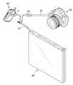
도 1a 및 도 1b를 참조하면, 본 발명의 이동식 단말기기(100)는 절첩부(110)에 의해 개방 및 폐쇄될 수 있다. 절첩부(110)에는 힌지부(미도시됨) 등이 형성되어 이동식 단말기기(100)의 개방 및 폐쇄를 가능하게 한다. 이하에서는 힌지부(미도시됨)가 형성되어 이동식 단말기기(100)의 개방 및 폐쇄 시 회전 축이 되는 부분을 포함하는 개념으로서 절첩부(110)라는 용어를 사용하기로 한다.1A and 1B, the
본 발명의 이동식 단말기기(100)는 절첩부(110)의 양단(111, 112) 사이에 연결될 수 있는 제1 케이블(120)을 포함한다. 제1 케이블(120)의 양단 중 일단은 절첩부(110)의 양단 중 일단에 고정되어 있을 수 있다. 또한, 제1 케이블(120)의 양단 중 타단은 절첩부(110)의 양단(111, 112) 중 타단에 탈착 가능하도록 고정될 수 있다. 그러나, 제1 케이블(120) 양단이 모두 각각 절첩부(110)의 양단(111, 112)에 탈착 가능하도록 고정될 수도 있다.The
제1 케이블(120)의 양단 중 일단은 절첩부(110)의 일단에 연결되어 이동식 단말기기(100)의 전원과 연결될 수 있다. 이동식 단말기기(100)의 전원은 배터리 등으로 구현될 수 있다. 이를 위해 제1 케이블(120)의 일단이 고정되거나 탈착 가능하게 연결되는 절첩부(110)의 일단은 회로적으로 이동식 단말기기(100)의 배터리와 전기적으로 연결되어 있을 수 있다. 제1 케이블(120)의 일단은 통상의 소켓 방식 등을 통해 절첩부(110)의 일단과 연결될 수 있다.One end of both ends of the
제1 케이블(120)의 타단은 절첩부(110)의 타단과 물리적으로 탈착 가능하게 연결된다. 본 발명의 일 실시예에 따르면, 절첩부(110)의 타단 및 제1 케이블(120)의 타단에는 고리가 형성될 수 있다. 절첩부(110)의 타단에 형성된 고리와 제1 케이블(120)의 타단에 형성된 고리는 서로 탈착 가능하게 연결될 수 있도록 구성되는 통상의 고리로서 구현될 수 있다. 제1 케이블(120)의 길이는 적절한 길이로 형성될 수 있다. 예를 들면, 제1 케이블(120)의 길이는 절첩부(110) 길이(l)보다 크게 형성될 수 있다. 사용자는 제1 케이블(120)의 양단을 절첩부(110)의 양단에 결합하여, 제1 케이블(120)을 손잡이 또는 몸에 매달 수 있는 끈으로 사용하여 이동식 단말기기(100)를 편리하게 들고 다닐 수 있다.The other end of the
한편, 제1 케이블(120)의 타단에는 제1 커넥터(121) 및 제2 커넥터(122)가 연결된다. 제1 커넥터(121)와 제2 커넥터(122)는 서로 암수 결합된다. 즉, 제1 커넥터(121)와 제2 커넥터(122)가 서로 탈착 가능하게 결합되되, 제1 커넥터(121)와 제2 커넥터(122) 중 어느 하나가 암 커넥터의 구성을 갖고, 다른 하나가 수 커넥터의 구성을 가짐으로써 서로 암수(female/male) 결합되어 미사용시에는 깔끔함을 유지할 수 있게 해준다. 본 발명의 일 실시예에 따르면, 제1 커넥터(121)는 USB(Universal Serial Bus) 커넥터의 수(male) 타입 단자가 삽입될 수 있는 암(female) 타입 단자일 수 있고, 제2 커넥터(122)는 UBS 커넥터의 암(female) 타입 단자일 수 있다.On the other hand, the other end of the
또한, 본 발명의 일 실시예에 따른 이동식 단말기기(100)는 절첩부(110)의 임의의 두 지점에 양단이 연결된 제2 케이블(130)을 더 포함할 수 있다. 이를 위해 절첩부(110)의 임의의 두 지점에는 결합부(113, 114)가 형성될 수 있다. 결합부(113, 114)는 제2 케이블(130)의 양단에 형성된 단자가 물리적으로 결합되어 고정될 수 있도록 해준다. 본 발명의 일 실시예에 따르면 제2 케이블(130)은 USB 케이블일 수 있고, 제2 케이블(130)의 일단 또는 양단은 USB 케이블의 수(male) 타입 단자일 수 있다. 제2 케이블(130)의 일단이 USB 케이블의 수(male) 타입 단자일 때, 타단은 암(female) 타입 단자일 수 있다. 제2 케이블(130)의 길이는 결합부(113, 114) 간의 거리보다 길게 형성될 수 있다. 이에 의해 사용자는 결합부(113, 114)에 양단이 결합된 제2 케이블을 손잡이로서 이용하여 이동식 단말기기(100)를 손쉽게 들고 다닐 수 있다.In addition, the mobile
도 1b는 본 발명의 일 실시예에 따른 이동식 단말기기(100)의 일 동작예를 나타낸 것이다.Figure 1b shows an operation example of the mobile
도 1b를 참조하면, 본 발명의 이동식 단말기기(100)에 탈착 가능하게 결합되는 제1 케이블(120)의 일단에 연결된 제1 커넥터(121)가 별도의 휴대 단말 장치(200)와 연결될 수 있다. 별도의 휴대 단말 장치(200)는 이동 전화기, 스마트폰(휴대전화에 인터넷 통신과 정보검색 등 컴퓨터 지원 기능을 추가한 지능형 단말기) 등일 수 있다. 앞선 설명에서 제1 커넥터(121)는 USB 커넥터의 수(male) 타입 단자인 것으로 예시하였으나, 제1 커넥터(121)는 이와는 다른 커넥터, 예를 들면, RS232/RS422 단자, DVI(Digital Visual Interface) 단자, RGB 단자, LVDS 단자, UART 단자 등 중 하나 이상으로 구성될 수도 있다. 이 때, 이에 대응하여 제1 케이블(120)은 RS232/RS422 케이블, DVI 케이블, RGB 케이블, LVDS 케이블, UART 케이블 등 중 하나 이상일 수 있다. 제1 커넥터(121)는 별도의 휴대 단말 장치(200)에 형성된 대응 단자를 통해 결합될 수 있다.Referring to FIG. 1B, a
제1 커넥터(121)가 휴대 단말 장치(200)와 전기적으로 연결됨에 따라 휴대 단말 장치(200)에는 이동식 단말기기(100)의 배터리로부터 전원을 공급받을 수 있다. 통상적으로 휴대 단말 장치(200)는 소용량의 배터리로 동작하는데, 후술할 고 성능 경통(예를 들면, 광학줌 기능을 갖는 렌즈 경통)을 포함하는 카메라 모듈(300)을 동작시키기 위해서는 대용량의 배터리가 필요하다. 본 발명의 일 실시예에 따르면, 휴대 단말 장치(200)가 상대적으로 대용량인 이동식 단말기기(100)의 배터리로부터 전원을 공급받기 때문에, 무리 없이 카메라 모듈(300)을 동작시킬 수 있게 된다.As the
또한, 본 발명의 일 실시예에 따르면, 제1 커넥터(121)가 휴대 단말 장치(200)와 전기적으로 연결됨에 따라 이동식 단말기기(100)와 휴대 단말 장치(200) 간 데이터 전달 경로가 형성되게 되고, 휴대 단말 장치(200)가 이동식 단말기기(100)의 프로세서(즉, 본체)로서의 역할을 할 수 있다. 이 때, 이동식 단말기기(100)의 디스플레이부(151; 도 2 참조)가 휴대 단말 장치(200)의 제어에 따른 표시부로서의 역할을 하게 된다. 또한, 본 발명의 다른 실시예에 따르면, 휴대 단말 장치(200)가 프로세서의 역할을 하고, 이동식 단말기기(100)의 자판부(143; 도 2 참조)가 동작 제어를 위한 입력부, 이동식 단말기기(100)의 디스플레이부(151)가 출력부로서의 역할을 할 수도 있게 된다. 이에 따라, 휴대 단말 장치(200)가 이동식 단말기기(100)의 대화면 디스플레이부(151) 또는 입력 자판부(143)를 활용할 수 있게 되며, 확장성, 편리성이 향상되게 된다. 그리고, 휴대 단말 장치(200)가 이동식 단말기기(100)의 본체로서의 역할을 대신할 수 있기 때문에, 이동식 단말기기(100)에는 본체 기능이 생략될 수도 있어 무게가 가벼워질 수 있고, 부피가 감소될 수도 있다. 또한, 이에 따라 이동식 단말기기(100)의 제품 가격도 현저히 낮아질 수 있게 된다.In addition, according to an embodiment of the present invention, as the
제1 케이블(120)의 일단에 연결되는 제2 커넥터(122)는 고성능 경통(예를 들면, 광학줌 기능을 갖는 렌즈 경통)을 포함하는 카메라 모듈(300)과 연결될 수 있다. 도 1b에서는 카메라 모듈(300)을 예시하였지만, 카메라 모듈(300) 외의 다른 장치, 예를 들면, 휴대 단말 장치(200)와 연동하여 동작할 수 있는 모듈 등의 장치가 제2 커넥터(122)와 연결될 수도 있다. 앞선 설명에서 제2 커넥터(122)는 USB 커넥터의 암(female) 타입 단자인 것으로 예시하였으나, 제2 커넥터(122)는 이와는 다른 커넥터, 예를 들면, RS232/RS422 단자, DVI(Digital Visual Interface) 단자, RGB 단자, LVDS 단자, UART 단자 등으로 구성될 수도 있다. 예를 들면, 제2 커넥터(122)가 UBS 커넥터의 암(female) 타입인 경우, 카메라 모듈(300)에 구비된 UBS 수(male) 타입 단자와 연결될 수 있다. 제2 커넥터(121)가 카메라 모듈(300)과 연결됨에 따라, 카메라 모듈(300)에 존재하는 데이터 또는 카메라 모듈(300)을 통해 수집되는 데이터가 제2 커넥터(122) 및 제1 커넥터(121)를 통해 휴대 단말 장치(200)로 전송될 수 있다. 또한, 휴대 단말 장치(200)로부터 입력되는 명령 또는 정보가 제1 커넥터(121) 및 제2 커넥터(122)를 통해 카메라 모듈(300)로 전송될 수도 있다.The
본 발명의 일 실시예에 따르면, 제2 커넥터(122)와 카메라 모듈(300) 사이에는 제2 케이블(130)이 연결될 수도 있다. 즉, 제2 케이블(130)의 양단이 각각 제2 커넥터(122)와 카메라 모듈(300)에 연결됨으로써 휴대 단말 장치(200)와 카메라 모듈(300) 간의 연결 거리를 연장할 수도 있다. 예를 들면, 제2 케이블(130)의 일단에 구비된 USB 수(male) 타입 단자가 제2 커넥터(122)에 연결되고, 제2 케이블(130)의 타단에 구비된 USB 수(male) 타입 단자 또는 암(female) 타입 단자가 카메라 모듈(300)과 연결될 수 있다. 제2 케이블(130)에 의해 카메라 모듈(300)의 이동성은 더욱 자유로워진다. 이에 따라, 카메라 모듈(300)은 멀리 떨어진 곳에 두어 원하는 장면을 촬영하고, 휴대 단말 장치(200)를 통해 해당 촬영 장면을 확인하는 것이 가능해진다. 예를 들면, 사용자가 위치하는 곳과 멀리 떨어진 곳(예를 들면, 높은 위치)에 카메라 모듈(300)을 두어 촬영을 해야하는 경우에도, 사용자는 확인 가능한 곳에 위치하는 휴대 단말 장치(200)를 통해 현재 카메라 모듈(300)이 촬영하고 있는 장면을 확인할 수 있다.According to an embodiment of the present invention, the
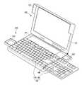
이하에서는 이동식 단말기기(100)의 개방 시 모습을 나타내는 도 2를 참조하여 이동식 단말기기(100)의 구성을 더욱 상세히 설명하기로 한다.Hereinafter, the configuration of the mobile
도 2를 참조하면, 이동식 단말기기(100)는 자판부를 포함하는 본체(140), 및 디스플레이부를 포함하는 덮개부(150)를 포함한다.Referring to FIG. 2, the mobile
본체(140)는 배터리 장착부(141), 제1 수납부(142), 자판부(143)를 포함할 수 있다.The
배터리 장착부(141)는 이동식 단말기기(100)의 동작에 필요한 전원을 공급하는 배터리가 장착되는 부분이다. 전술한 바와 같이 제1 케이블(120) 및 제1 커넥터(121)를 통해 이동식 단말기기(100)와 별도의 휴대 단말 장치(200)가 연결되는 경우에는 배터리 장착부(141)에 장착된 배터리로부터의 전원이 휴대 단말 장치(200)로도 공급될 수 있다. 본 발명의 일 실시예에 따르면, 배터리 장착부(141)가 본체(140)의 상부, 즉, 절첩부(110)와 최대한 가깝게 위치하고 있기 때문에, 덮개부(150)에 형성된 디스플레이부(151)로 전원을 공급할 시의 전력 손실이 최소화될 수 있다. 배터리 장착부(141) 근처, 예를 들면, 배터리 장착부(141)의 양측부 중 일측부에는 제1 수납부(142)가 형성된다. 제1 수납부(142)는 이동식 단말기기(100)와 제1 케이블(120) 및 제2 커넥터(122)를 통해 연결될 수 있는 카메라 모듈(300)이 수납되는 부분일 수 있으나, 이와는 다른 물건이 수납될 수도 있다. 제1 수납부(142)는 뚜껑에 의해 개폐되는 형태로 구현될 수도 있고, 본체(140)의 측부로부터 인출 및 인입이 가능한 서랍 형태로 구현될 수도 있다. 도 2는 서랍 형태로 구현된 제1 수납부(142)의 일례를 나타낸다.The
본 발명의 일 실시예에 따르면, 본체(140)는 절첩 가능한 자판부(143)를 포함한다. 자판부(143)에는 힌지부(144)가 형성되어 있어서, 힌지부(144)를 축으로 하여 절첩 가능하다.According to an embodiment of the present invention, the
도 2는 자판부(143)가 펼쳐진 경우의 구성을 나타내는 도면이며, 도 3은 자판부(143)가 힌지부(144)를 축으로 하여 접혀진 경우의 구성을 나타내는 도면이다.FIG. 2 is a diagram showing the configuration when the
자판부(143)는 문자 입력을 가능하게 하는 제1 부분(145), 숫자키 및 방향키를 포함하는 제2 부분(146)으로 구성된다. 문자 입력을 가능하게 하는 부분은 QWERTY 자판으로 구성될 수 있다. 제1 부분(145)과 제2 부분(146)의 경계에는 힌지부(144)가 형성된다. 제1 부분(145)은 본체(140)에 고정되며, 그 너비는 본체(140)의 너비와 실질적으로 동일할 수 있다. 힌지부(144)는 본체(140)의 양측단 중 어느 한 측단을 따라 형성될 수 있고, 제2 부분(146)은 힌지부(144)를 축으로 하여 절첩 가능하다. 통상적으로 문자 자판을 포함하는 제1 부분(145)의 너비가 숫자키 및 방향키를 포함하는 제2 부분(146)에 비해 넓은 폭을 갖는다. 따라서, 도 3에 도시되는 바와 같이, 제2 부분(146)을 힌지부(144)를 축으로 하여 제1 부분(145)에 대해 접었을 시에는 제1 부분(145) 상에 소정 공간이 생기게 된다. 해당 공간의 너비는 제1 부분(145)과 제2 부분(146)의 너비 차와 동일하고, 높이는 제2 부분(146)의 높이와 동일하다. 이 공간은 소정의 물건이 놓이는 수납공간으로서 기능할 수 있다. 예를 들면, 이 공간은 제2 수납부(147)로서 기능할 수 있으며, 여기에는 지갑 등이 수납될 수 있다. 도 3에는 제2 수납부(147)에 단순히 지갑이 놓여지는 경우를 도시하였으나, 이와는 달리 배터리 장착부(141)의 하단측에 형성되는 힌지부(미도시됨)를 축으로 하여 절첩 가능한 제2 수납부(147)가 형성될 수도 있다. 이에 따르면, 사용자가 이동식 단말기기(100)를 사용하지 않을 시에는 제2 수납부(147)를 자판부(143)의 제1 부분(145) 상에 놓이도록 하고, 이동식 단말기기(100)를 사용할 시에는 제2 수납부(147)를 힌지부를 축으로 하여 회전시켜 배터리 장착부(141) 상에 놓이도록 할 수 있다.The
본 발명의 일 실시예에 따르면 본체(140)에 있어서 자판부(143)의 하면 부분에는 제3 수납부(148)가 더 형성될 수도 있다. 제3 수납부(148)는 본체(140)의 측부로부터 인출 및 인입 가능하도록 서랍 형태로 형성될 수 있다.According to an embodiment of the present invention, a third
한편, 본 발명의 일 실시예에 따른 덮개부(150)는 디스플레이부(151)를 포함하고, 절첩부(110)를 축으로 하여 본체(140)에 대해 개폐된다. 덮개부(150)의 모서리부 중 적어도 일부에는 날개부(152)가 형성된다. 날개부(152)는 덮개부(150)가 본체(140)에 대해 폐쇄되었을 때, 본체(140)의 테두리를 감싸는 기능을 수행한다. 이에 의해 자판부(143)의 제1 부분(145) 상의 제2 수납부(147)에 불안정하게 놓인 지갑 등이 본체(140) 밖으로 이탈되지 않도록 한다. 도면에서는 날개부(152)가 덮개부(150)의 가장자리 중 절첩부(111)가 형성된 모서리를 제외한 나머지 모서리에 형성되는 것으로 도시되었으나, 이와는 달리, 그 중 일부에만 형성될 수도 있다.On the other hand, the
이상에서 본 발명이 구체적인 구성요소 등과 같은 특정 사항들과 한정된 실시예 및 도면에 의해 설명되었으나, 이는 본 발명의 보다 전반적인 이해를 돕기 위해서 제공된 것일 뿐, 본 발명이 상기 실시예들에 한정되는 것은 아니며, 본 발명이 속하는 기술분야에서 통상적인 지식을 가진 자라면 이러한 기재로부터 다양한 수정 및 변형을 꾀할 수 있다.Although the present invention has been described by specific embodiments such as specific components and the like, but the embodiments and the drawings are provided to assist in a more general understanding of the present invention, the present invention is not limited to the above embodiments. For those skilled in the art, various modifications and variations can be made from these descriptions.
따라서, 본 발명의 사상은 상기 설명된 실시예에 국한되어 정해져서는 아니되며, 후술하는 특허청구범위뿐만 아니라 이 특허청구범위와 균등하게 또는 등가적으로 변형된 모든 것들은 본 발명의 사상의 범주에 속한다고 할 것이다.
Therefore, the spirit of the present invention should not be limited to the embodiments described above, and all of the equivalents or equivalents of the claims, as well as the claims below, are included in the scope of the spirit of the present invention. I will say.
100: 이동식 단말기기
200: 휴대 단말 장치
110: 절첩부
111, 112: 절첩부 양단
113, 114: 결합부
120: 제1 케이블
121: 제1 커넥터
122: 제2 커넥터
130: 제2 케이블
140: 본체
141: 배터리 장착부
142: 제1 수납부
143: 자판부
147: 제2 수납부
148: 제3 수납부
150: 덮개부
151: 디스플레이부
152: 날개부100: mobile terminal device
200: mobile terminal device
110: fold
111, 112: Fold ends
113, 114: coupling part
120: first cable
121: first connector
122: second connector
130: second cable
140: main body
141: battery compartment
142: first storage
143: keyboard
147: second storage portion
148: third storage portion
150: cover part
151: display unit
152: wing
Claims (12)
Translated fromKorean디스플레이부를 포함하며, 상기 본체의 일 모서리에 형성된 절첩부를 축으로 개폐되는 덮개부; 및
양단이 상기 절첩부의 양단에 결합되며, 일단에는 휴대 단말 장치와 연결 가능한 제1 커넥터, 및 외부장치와 연결 가능한 제2 커넥터가 형성된 제1 케이블을 포함하는 이동식 단말기기.A main body including a keyboard;
A cover part including a display part and opening and closing a folding part formed at one corner of the main body by a shaft; And
Both ends are coupled to both ends of the folding portion, and a mobile terminal device comprising a first cable having a first connector connected to the portable terminal device, and a second connector connectable to an external device.
상기 절첩부에 형성되는 2개의 결합부에 양단이 탈착 가능하게 결합되며, 분리시 양단이 각각 상기 제2 커넥터와 상기 외부장치와 연결 가능한 제2 케이블을 더 포함하는 이동식 단말기기.The method of claim 1,
Both ends are detachably coupled to the two coupling portions formed in the folding portion, the mobile terminal device further comprises a second cable at both ends can be connected to the second connector and the external device, respectively.
상기 제1 커넥터와 제2 커넥터는 서로 맞물리는 형태로 결합 가능한 이동식 단말기기.The method of claim 1,
The first connector and the second connector is a mobile terminal device capable of coupling in the form of engagement with each other.
상기 제1 케이블은 상기 제1 커넥터를 통해 상기 휴대 단말 장치에 전원을 공급하는 이동식 단말기기.The method of claim 1,
The first cable is a mobile terminal device for supplying power to the portable terminal device through the first connector.
상기 제1 케이블 및 상기 제1 커넥터는 상기 이동식 단말기기와 상기 휴대 단말 장치 간의 데이터 전달 경로가 되는 이동식 단말기기.The method of claim 1,
And the first cable and the first connector are data transfer paths between the mobile terminal and the portable terminal device.
상기 제1 케이블이 상기 제1 커넥터를 통해 상기 휴대 단말 장치와 연결될 때,
상기 디스플레이부는 상기 휴대 단말 장치에 의해 구동되는 동작을 디스플레이하는 이동식 단말기기.The method of claim 5,
When the first cable is connected with the portable terminal device through the first connector,
And the display unit displays an operation driven by the portable terminal device.
상기 제1 케이블이 상기 제1 커넥터를 통해 상기 휴대 단말 장치와 연결될 때,
상기 자판부에 의해 상기 휴대 단말 장치의 동작이 제어되는 이동식 단말기기.The method of claim 5,
When the first cable is connected with the portable terminal device through the first connector,
A mobile terminal device in which the operation of the portable terminal device is controlled by the keyboard unit.
상기 외부장치는 카메라 모듈이고, 상기 카메라 모듈을 통해 수집된 영상은 상기 제2 커넥터와 제1 커넥터를 통해 상기 휴대 단말 장치에 전달되는 이동식 단말기기.The method of claim 1,
The external device is a camera module, and the image collected through the camera module is transferred to the mobile terminal device through the second connector and the first connector.
상기 본체의 적어도 일부에는 절첩 가능한 자판부가 형성된 이동식 단말기기.The method of claim 1,
At least a portion of the main body is a mobile terminal device is formed a collapsible keyboard.
상기 절첩 가능한 자판부는,
문자키들을 포함하는 제1 부분; 및
방향키 및 숫자키를 포함하는 제2 부분을 포함하고,
상기 제1 부분은 상기 본체에 고정되어 있으며, 상기 제2 부분은 상기 제1 부분과 제2 부분의 경계에 형성되는 힌지부를 통해 상기 제1 부분에 대해 절첩이 가능한 이동식 단말기기.10. The method of claim 9,
The foldable keyboard part,
A first portion comprising character keys; And
A second part including a direction key and a numeric key,
And the first portion is fixed to the main body, and the second portion is foldable with respect to the first portion via a hinge portion formed at a boundary between the first portion and the second portion.
상기 제1 부분 상에 있어서, 상기 제2 부분이 상기 제1 부분에 대해 접힐 때, 상기 제2 부분에 의해 덮히지 않는 공간에는 수납부가 형성되는 이동식 단말기기.The method of claim 10,
And a receiving portion is formed in the space not covered by the second portion when the second portion is folded with respect to the first portion on the first portion.
상기 본체에 있어서, 상기 절첩부와 인접한 공간에는 배터리 장착부가 형성되고, 상기 자판부는 상기 배터리 장착부를 사이에 두고 상기 절첩부와 이격되어 형성되는 이동식 단말기기.
10. The method of claim 9,
In the main body, a battery mounting portion is formed in a space adjacent to the folding portion, the keyboard portion is a mobile terminal device formed spaced apart from the folding portion with the battery mounting portion therebetween.
Priority Applications (2)
| Application Number | Priority Date | Filing Date | Title |
|---|---|---|---|
| KR1020110049560AKR101879873B1 (en) | 2011-05-25 | 2011-05-25 | Portable terminal |
| PCT/KR2012/004159WO2012161548A2 (en) | 2011-05-25 | 2012-05-25 | Mobile terminal device |
Applications Claiming Priority (1)
| Application Number | Priority Date | Filing Date | Title |
|---|---|---|---|
| KR1020110049560AKR101879873B1 (en) | 2011-05-25 | 2011-05-25 | Portable terminal |
Publications (2)
| Publication Number | Publication Date |
|---|---|
| KR20120131411Atrue KR20120131411A (en) | 2012-12-05 |
| KR101879873B1 KR101879873B1 (en) | 2018-07-18 |
Family
ID=47217925
Family Applications (1)
| Application Number | Title | Priority Date | Filing Date |
|---|---|---|---|
| KR1020110049560AActiveKR101879873B1 (en) | 2011-05-25 | 2011-05-25 | Portable terminal |
Country Status (2)
| Country | Link |
|---|---|
| KR (1) | KR101879873B1 (en) |
| WO (1) | WO2012161548A2 (en) |
Cited By (1)
| Publication number | Priority date | Publication date | Assignee | Title |
|---|---|---|---|---|
| FR3029042A1 (en)* | 2014-11-25 | 2016-05-27 | Orange | DEVICE FOR INTERNET ACCESS VIA A MOBILE COMMUNICATION NETWORK |
Family Cites Families (7)
| Publication number | Priority date | Publication date | Assignee | Title |
|---|---|---|---|---|
| KR100402711B1 (en)* | 1999-07-31 | 2003-10-22 | 서유진 | Disk storage device |
| KR200202131Y1 (en)* | 2000-03-27 | 2000-11-15 | 박상훈 | Information handling terminal |
| JP2003005270A (en)* | 2001-06-27 | 2003-01-08 | Canon Inc | Connection cable for camera |
| JP2004118794A (en)* | 2002-09-30 | 2004-04-15 | Brother Ind Ltd | Input device having a windable display and a foldable keyboard, and a personal computer having the input device |
| US20050085278A1 (en)* | 2003-10-15 | 2005-04-21 | Chao-Hua Lin | Data and charge adaptor for mobile device |
| KR20060069017A (en)* | 2004-12-17 | 2006-06-21 | 엘지전자 주식회사 | Device with portable terminal holder |
| KR20100083580A (en)* | 2009-01-14 | 2010-07-22 | 정관선 | System for driving mobile device using monitor and method thereof |
- 2011
- 2011-05-25KRKR1020110049560Apatent/KR101879873B1/enactiveActive
- 2012
- 2012-05-25WOPCT/KR2012/004159patent/WO2012161548A2/enactiveApplication Filing
Cited By (2)
| Publication number | Priority date | Publication date | Assignee | Title |
|---|---|---|---|---|
| FR3029042A1 (en)* | 2014-11-25 | 2016-05-27 | Orange | DEVICE FOR INTERNET ACCESS VIA A MOBILE COMMUNICATION NETWORK |
| WO2016083715A1 (en)* | 2014-11-25 | 2016-06-02 | Orange | Device for internet access via a mobile communication network |
Also Published As
| Publication number | Publication date |
|---|---|
| KR101879873B1 (en) | 2018-07-18 |
| WO2012161548A2 (en) | 2012-11-29 |
| WO2012161548A3 (en) | 2013-03-21 |
Similar Documents
| Publication | Publication Date | Title |
|---|---|---|
| KR101641229B1 (en) | Module for expanding function of electronic device and mobile device having the same | |
| US9785191B2 (en) | Asymmetric computer tablet and docking system | |
| US20210223825A1 (en) | Computing device modules | |
| US8284543B2 (en) | Structure of keyboard combinable with electronic device | |
| KR20190065416A (en) | Modular Computing System | |
| US20120281356A1 (en) | Cases for tablet computers and methods | |
| JP7636504B2 (en) | Display device | |
| KR102167051B1 (en) | Portable device | |
| US20100069117A1 (en) | USB enabled mobile phone handset | |
| EP2887179B1 (en) | Protective cover for electronic device | |
| KR101546053B1 (en) | Portable Memory Drive of Multi-purpose | |
| US6215985B1 (en) | Mobile communicator | |
| JP2009267490A (en) | Expansion apparatus | |
| CN101770155A (en) | Portable electronic product with projection device | |
| KR20120131411A (en) | Portable terminal | |
| CN111684389B (en) | Portable device for processing, transmitting and receiving information, sound and video | |
| KR102215610B1 (en) | Folding multimedia terminal | |
| CN207777932U (en) | A kind of built-in more folding apparatus and the portable computer comprising the equipment | |
| JP6105793B1 (en) | Electronic device and keyboard device | |
| GB2611723A (en) | Display apparatus | |
| KR20070069263A (en) | Battery Packs for Notebook Computers with Port Replicators | |
| JP2008205724A (en) | Personal digital assistant |
Legal Events
| Date | Code | Title | Description |
|---|---|---|---|
| PA0109 | Patent application | St.27 status event code:A-0-1-A10-A12-nap-PA0109 | |
| R18-X000 | Changes to party contact information recorded | St.27 status event code:A-3-3-R10-R18-oth-X000 | |
| PN2301 | Change of applicant | St.27 status event code:A-3-3-R10-R13-asn-PN2301 St.27 status event code:A-3-3-R10-R11-asn-PN2301 | |
| R17-X000 | Change to representative recorded | St.27 status event code:A-3-3-R10-R17-oth-X000 | |
| PG1501 | Laying open of application | St.27 status event code:A-1-1-Q10-Q12-nap-PG1501 | |
| PN2301 | Change of applicant | St.27 status event code:A-3-3-R10-R13-asn-PN2301 St.27 status event code:A-3-3-R10-R11-asn-PN2301 | |
| R18-X000 | Changes to party contact information recorded | St.27 status event code:A-3-3-R10-R18-oth-X000 | |
| R18-X000 | Changes to party contact information recorded | St.27 status event code:A-3-3-R10-R18-oth-X000 | |
| R17-X000 | Change to representative recorded | St.27 status event code:A-3-3-R10-R17-oth-X000 | |
| PN2301 | Change of applicant | St.27 status event code:A-3-3-R10-R13-asn-PN2301 St.27 status event code:A-3-3-R10-R11-asn-PN2301 | |
| R18-X000 | Changes to party contact information recorded | St.27 status event code:A-3-3-R10-R18-oth-X000 | |
| PA0201 | Request for examination | St.27 status event code:A-1-2-D10-D11-exm-PA0201 | |
| PN2301 | Change of applicant | St.27 status event code:A-3-3-R10-R13-asn-PN2301 St.27 status event code:A-3-3-R10-R11-asn-PN2301 | |
| P11-X000 | Amendment of application requested | St.27 status event code:A-2-2-P10-P11-nap-X000 | |
| P13-X000 | Application amended | St.27 status event code:A-2-2-P10-P13-nap-X000 | |
| E902 | Notification of reason for refusal | ||
| PE0902 | Notice of grounds for rejection | St.27 status event code:A-1-2-D10-D21-exm-PE0902 | |
| PN2301 | Change of applicant | St.27 status event code:A-3-3-R10-R13-asn-PN2301 St.27 status event code:A-3-3-R10-R11-asn-PN2301 | |
| T11-X000 | Administrative time limit extension requested | St.27 status event code:U-3-3-T10-T11-oth-X000 | |
| T11-X000 | Administrative time limit extension requested | St.27 status event code:U-3-3-T10-T11-oth-X000 | |
| E13-X000 | Pre-grant limitation requested | St.27 status event code:A-2-3-E10-E13-lim-X000 | |
| P11-X000 | Amendment of application requested | St.27 status event code:A-2-2-P10-P11-nap-X000 | |
| P13-X000 | Application amended | St.27 status event code:A-2-2-P10-P13-nap-X000 | |
| E701 | Decision to grant or registration of patent right | ||
| PE0701 | Decision of registration | St.27 status event code:A-1-2-D10-D22-exm-PE0701 | |
| GRNT | Written decision to grant | ||
| PR0701 | Registration of establishment | St.27 status event code:A-2-4-F10-F11-exm-PR0701 | |
| PR1002 | Payment of registration fee | St.27 status event code:A-2-2-U10-U11-oth-PR1002 Fee payment year number:1 | |
| PG1601 | Publication of registration | St.27 status event code:A-4-4-Q10-Q13-nap-PG1601 | |
| R18-X000 | Changes to party contact information recorded | St.27 status event code:A-5-5-R10-R18-oth-X000 | |
| PR1001 | Payment of annual fee | St.27 status event code:A-4-4-U10-U11-oth-PR1001 Fee payment year number:4 | |
| R18-X000 | Changes to party contact information recorded | St.27 status event code:A-5-5-R10-R18-oth-X000 | |
| PR1001 | Payment of annual fee | St.27 status event code:A-4-4-U10-U11-oth-PR1001 Fee payment year number:5 | |
| PR1001 | Payment of annual fee | St.27 status event code:A-4-4-U10-U11-oth-PR1001 Fee payment year number:6 | |
| PR1001 | Payment of annual fee | St.27 status event code:A-4-4-U10-U11-oth-PR1001 Fee payment year number:7 | |
| P14-X000 | Amendment of ip right document requested | St.27 status event code:A-5-5-P10-P14-nap-X000 | |
| PR1001 | Payment of annual fee | St.27 status event code:A-4-4-U10-U11-oth-PR1001 Fee payment year number:8 |