KR20120129488A - Magnetic connecting device - Google Patents
Magnetic connecting deviceDownload PDFInfo
- Publication number
- KR20120129488A KR20120129488AKR1020110047769AKR20110047769AKR20120129488AKR 20120129488 AKR20120129488 AKR 20120129488AKR 1020110047769 AKR1020110047769 AKR 1020110047769AKR 20110047769 AKR20110047769 AKR 20110047769AKR 20120129488 AKR20120129488 AKR 20120129488A
- Authority
- KR
- South Korea
- Prior art keywords
- power
- external device
- terminal
- connector
- communication terminal
- Prior art date
- Legal status (The legal status is an assumption and is not a legal conclusion. Google has not performed a legal analysis and makes no representation as to the accuracy of the status listed.)
- Ceased
Links
- 230000005291magnetic effectEffects0.000titleclaimsabstractdescription53
- 238000004891communicationMethods0.000claimsabstractdescription122
- 238000000034methodMethods0.000claimsdescription44
- 230000005298paramagnetic effectEffects0.000claimsdescription14
- 230000005294ferromagnetic effectEffects0.000claimsdescription13
- 239000002907paramagnetic materialSubstances0.000claimsdescription12
- 239000003302ferromagnetic materialSubstances0.000claimsdescription11
- 239000000696magnetic materialSubstances0.000claimsdescription6
- 238000012546transferMethods0.000abstractdescription9
- 230000008878couplingEffects0.000abstractdescription3
- 238000010168coupling processMethods0.000abstractdescription3
- 238000005859coupling reactionMethods0.000abstractdescription3
- 238000009499grossingMethods0.000description7
- 238000004804windingMethods0.000description5
- 230000006641stabilisationEffects0.000description3
- 238000011105stabilizationMethods0.000description3
- 230000005540biological transmissionEffects0.000description2
- 238000013461designMethods0.000description2
- 230000006866deteriorationEffects0.000description2
- 238000010586diagramMethods0.000description2
- 239000000463materialSubstances0.000description2
- 239000003381stabilizerSubstances0.000description2
- 230000000087stabilizing effectEffects0.000description2
- 238000006243chemical reactionMethods0.000description1
- 238000010276constructionMethods0.000description1
- 238000011161developmentMethods0.000description1
- 238000005516engineering processMethods0.000description1
- 230000006698inductionEffects0.000description1
- 230000001939inductive effectEffects0.000description1
- 238000004519manufacturing processMethods0.000description1
- 230000002093peripheral effectEffects0.000description1
- 238000000926separation methodMethods0.000description1
- 238000005728strengtheningMethods0.000description1
Images


Classifications
- H—ELECTRICITY
- H01—ELECTRIC ELEMENTS
- H01R—ELECTRICALLY-CONDUCTIVE CONNECTIONS; STRUCTURAL ASSOCIATIONS OF A PLURALITY OF MUTUALLY-INSULATED ELECTRICAL CONNECTING ELEMENTS; COUPLING DEVICES; CURRENT COLLECTORS
- H01R13/00—Details of coupling devices of the kinds covered by groups H01R12/70 or H01R24/00 - H01R33/00
- H01R13/62—Means for facilitating engagement or disengagement of coupling parts or for holding them in engagement
- H01R13/6205—Two-part coupling devices held in engagement by a magnet
- H—ELECTRICITY
- H01—ELECTRIC ELEMENTS
- H01R—ELECTRICALLY-CONDUCTIVE CONNECTIONS; STRUCTURAL ASSOCIATIONS OF A PLURALITY OF MUTUALLY-INSULATED ELECTRICAL CONNECTING ELEMENTS; COUPLING DEVICES; CURRENT COLLECTORS
- H01R11/00—Individual connecting elements providing two or more spaced connecting locations for conductive members which are, or may be, thereby interconnected, e.g. end pieces for wires or cables supported by the wire or cable and having means for facilitating electrical connection to some other wire, terminal, or conductive member, blocks of binding posts
- H01R11/11—End pieces or tapping pieces for wires, supported by the wire and for facilitating electrical connection to some other wire, terminal or conductive member
- H01R11/30—End pieces held in contact by a magnet
- H—ELECTRICITY
- H02—GENERATION; CONVERSION OR DISTRIBUTION OF ELECTRIC POWER
- H02J—CIRCUIT ARRANGEMENTS OR SYSTEMS FOR SUPPLYING OR DISTRIBUTING ELECTRIC POWER; SYSTEMS FOR STORING ELECTRIC ENERGY
- H02J7/00—Circuit arrangements for charging or depolarising batteries or for supplying loads from batteries
- H02J7/0042—Circuit arrangements for charging or depolarising batteries or for supplying loads from batteries characterised by the mechanical construction
- H02J7/0044—Circuit arrangements for charging or depolarising batteries or for supplying loads from batteries characterised by the mechanical construction specially adapted for holding portable devices containing batteries
Landscapes
- Engineering & Computer Science (AREA)
- Power Engineering (AREA)
- Charge And Discharge Circuits For Batteries Or The Like (AREA)
- Details Of Connecting Devices For Male And Female Coupling (AREA)
- Near-Field Transmission Systems (AREA)
Abstract
Translated fromKoreanDescription
Translated fromKorean본 발명은 통신형 전원 마그네틱 커넥터를 갖는 마그네틱 커넥팅 장치에 관한 것이다.
The present invention relates to a magnetic connecting device having a communication power supply magnetic connector.
일반적으로 휴대폰, 스마트폰 및 PDA(Personal Digital Assistant)와 같은 모바일단말기는 이동성이 좋고, 휴대가 간편하여 보편적으로 사용되고 있다. 이에 따라 모바일단말기의 배터리를 충전하는 유선 충전기도 제조된 배터리의 형태나 규격에 맞추어 서로 다른 형태로 제조되고 있고, 소비자의 요구에 부합되도록 모바일단말기의 기능 향상과 경량화를 추구하려는 경향으로 인하여 동일한 제조업체에서도 다양한 형태의 모바일단말기와 이에 맞는 다양한 형태의 충전기가 제조되고 있다.In general, mobile terminals such as mobile phones, smart phones, and PDAs (Personal Digital Assistants) are widely used because of their good mobility and ease of portability. Accordingly, wired chargers that charge the battery of the mobile terminal are also manufactured in different forms according to the type or size of the manufactured battery, and the same manufacturers due to the tendency to improve the functionality and weight of the mobile terminal to meet the needs of consumers. Also in various forms of mobile terminals and various types of chargers are being manufactured.
최근에는 기술의 발달에 따라 새로운 충전기가 보급되고 있다. 이러한 충전기로는 기존의 충전 방식의 문제점을 해결하기 위하여 전기적 접촉없이 자기유도 방식을 이용하여 배터리를 충전하는 무접점 충전 방식이 사용되고 있다.Recently, new chargers have been widely used according to the development of technology. In order to solve the problem of the conventional charging method, a non-contact charging method for charging a battery using a magnetic induction method without an electrical contact is used as the charger.
이러한 무접점 충전 방식인 무선전력전송기기(Inductive Charger)의 경우에는 충전을 위해 외부기기를 충전패드에 올려놓거나 거치하는 형태를 통해 무선으로 전력을 전송하는 편리한 측면이 있다. 하지만, 에너지전달 측면에서 충전패드와 충전기 사이의 비접촉 공간에 크기에 따라 그 효율이 떨어지고, 설계가 비교적 복잡할 수 있으며, 제조 단가도 비싸다는 문제점이 있다.
In the case of the inductive charger, which is a contactless charging method, there is a convenient aspect of transmitting power wirelessly by placing or mounting an external device on a charging pad for charging. However, in terms of energy transfer, the efficiency may be reduced depending on the size of the non-contact space between the charging pad and the charger, the design may be relatively complicated, and the manufacturing cost may be expensive.
본 발명은 통신형 마그네틱 커넥터를 통해 외부기기와 자기적 및 전기적으로 결합하고, 결합시에 통신을 통해 외부기기를 확인한 후 동작전원을 전달함으로써, 사용상의 편의성과 안전성을 확보할 수 있는 마그네틱 커넥팅 장치를 제공하기 위한 것이다.The present invention magnetically and electrically coupled to an external device through a communication type magnetic connector, and by confirming the external device through the communication at the time of coupling, by transmitting the operating power, a magnetic connecting device that can ensure the convenience and safety of use It is to provide.
본 발명이 이루고자 하는 기술적 과제들은 이상에서 언급한 기술적 과제들로 제한되지 않으며, 언급되지 않은 다른 기술적 과제들은 아래의 기재로부터 본 발명이 속하는 기술분야에서 통상의 지식을 가진 자에게 명확하게 이해될 수 있을 것이다.
It is to be understood that both the foregoing general description and the following detailed description are exemplary and explanatory and are not intended to limit the invention to the particular embodiments that are described. It is to be understood that both the foregoing general description and the following detailed description are exemplary and explanatory and are not restrictive of the invention, There will be.
상기 목적을 달성하기 위한 본 발명의 커넥팅 장치는, 외부기기의 커넥터와 자기적으로 결합되며 전원을 외부기기로 전달하는 복수의 전원단자; 및 상기 복수의 전원단자에 인접하여 배치되어 상기 외부기기의 커넥터와 접촉되고 외부기기의 결합시 데이터가 송수신되는 적어도 하나의 통신단자;를 포함할 수 있다.The connecting device of the present invention for achieving the above object, a plurality of power terminals that are magnetically coupled to the connector of the external device and transfers power to the external device; And at least one communication terminal disposed adjacent to the plurality of power terminals to be in contact with a connector of the external device and to transmit and receive data when the external device is coupled.
구체적으로, 상기 복수의 전원단자는 서로 다른 극성의 자성체로 형성될 수 있고, 상기 전원단자는 영구자석, 강자성체 및 상자성체 중 어느 하나로 구성될 수 있다.Specifically, the plurality of power terminals may be formed of magnetic materials having different polarities, and the power terminals may be formed of any one of a permanent magnet, a ferromagnetic body, and a paramagnetic body.
상기 전원단자는 직류전원 또는 교류전원을 외부기기로 전달할 수 있다.The power terminal may transmit DC power or AC power to an external device.
상기 통신단자는 영구자석, 강자성체 및 상자성체 중 어느 하나로 구성될 수 있다.The communication terminal may be configured of any one of a permanent magnet, a ferromagnetic material, and a paramagnetic material.
상기 외부기기의 결합시에 상기 통신단자를 통해 외부기기의 연결 여부를 확인한 후 상기 전원단자를 통한 외부기기로의 전원공급 여부를 제어하는 제어부를 더 포함할 수 있고, 상기 제어부는 외부기기의 결합시에 외부기기로부터 읽어온 식별정보와 미리 설정된 식별정보를 상호 비교하여 전원공급 여부를 결정할 수 있다.The control unit may further include a control unit for controlling whether to supply power to an external device through the power terminal after checking whether the external device is connected through the communication terminal when the external device is coupled. The identification information read from the external device and the predetermined identification information may be compared with each other to determine whether to supply power.
상기 제어부는, 외부기기의 결합시에 외부기기로 식별정보를 요청하고, 외부기기로부터 읽어온 식별정보를 미리 설정된 식별정보와 상호 비교하는 통신제어부; 및 상기 통신제어부의 비교 결과에 따라 스위치부를 제어하여 외부기기로의 전원공급 여부를 제어하는 전원제어부;를 포함할 수 있으며, 상기 스위치부는 직류출력단과 전원단자 사이에 배치되거나 교류출력단과 전원단자 사이에 배치될 수 있다.The control unit may include: a communication control unit for requesting identification information from an external device when the external device is combined, and comparing the identification information read from the external device with preset identification information; And a power control unit controlling the power supply to an external device by controlling the switch unit according to the comparison result of the communication control unit, wherein the switch unit is disposed between the DC output terminal and the power terminal or between the AC output terminal and the power terminal. Can be placed in.
상기 목적을 달성하기 위한 본 발명의 다른 커넥팅 장치는, 외부기기의 커넥터와 결합되며 전원을 외부기기로 전달하는 복수의 전원단자; 및 상기 복수의 전원단자에 인접하여 배치되어 외부기기의 커넥터와 자기적으로 결합되며, 외부기기의 결합시 데이터가 송수신되는 적어도 하나의 통신단자;를 포함할 수 있다.Another connecting device of the present invention for achieving the above object is coupled to the connector of the external device and a plurality of power terminals for transmitting power to the external device; And at least one communication terminal disposed adjacent to the plurality of power terminals and magnetically coupled to a connector of an external device, and data is transmitted and received when the external device is coupled.
구체적으로, 상기 복수의 전원단자는 서로 다른 극성의 자성체로 형성될 수 있고, 상기 전원단자는 영구자석, 강자성체 및 상자성체 중 어느 하나로 구성될 수 있다.Specifically, the plurality of power terminals may be formed of magnetic materials having different polarities, and the power terminals may be formed of any one of a permanent magnet, a ferromagnetic body, and a paramagnetic body.
상기 전원단자는 직류전원 또는 교류전원을 외부기기로 전달할 수 있다.The power terminal may transmit DC power or AC power to an external device.
상기 통신단자는 영구자석, 강자성체 및 상자성체 중 어느 하나로 구성될 수 있다.The communication terminal may be configured of any one of a permanent magnet, a ferromagnetic material, and a paramagnetic material.
상기 목적을 달성하기 위한 본 발명의 또다른 커넥팅 장치는, 전원공급기의 커넥터와 자기적으로 결합되며 전원을 전원공급기로부터 전달받은 복수의 전원단자; 및 상기 복수의 전원단자에 인접하여 배치되어 상기 전원공급기의 커넥터와 접촉되고 전원공급기의 결합시 데이터가 송수신되는 적어도 하나의 통신단자;를 포함할 수 있다.Another connecting device of the present invention for achieving the above object, a plurality of power terminals magnetically coupled to the connector of the power supply and received power from the power supply; And at least one communication terminal disposed adjacent to the plurality of power terminals to be in contact with the connector of the power supply and to transmit and receive data when the power supply is coupled.
상기 목적을 달성하기 위한 본 발명의 또다른 커넥팅 장치는, 전원공급기의 커넥터와 결합되며 전원을 전원공급기로부터 전달받는 복수의 전원단자; 및 상기 복수의 전원단자에 인접하여 배치되어 전원공급기의 커넥터와 자기적으로 결합되며, 전원공급기의 결합시 데이터가 송수신되는 적어도 하나의 통신단자;를 포함할 수 있다.Another connecting device of the present invention for achieving the above object is a plurality of power terminals coupled to the connector of the power supply and receiving power from the power supply; And at least one communication terminal disposed adjacent to the plurality of power terminals to be magnetically coupled to the connector of the power supply and to which data is transmitted and received when the power supply is coupled.
구체적으로, 상기 전원공급기의 결합시에 상기 통신단자를 통해 식별정보가 요청되면 미리 저장된 식별정보를 전원공급기로 전달하는 통신제어부를 더 포함할 수 있다.In detail, when identification information is requested through the communication terminal when the power supply is coupled, the communication control unit may further include a communication control unit which transmits the previously stored identification information to the power supply.
상기 목적을 달성하기 위한 본 발명의 또다른 커넥팅 장치는, 외부기기의 커넥터와 자기적으로 결합되며 전원을 외부기기로 전달하는 복수의 전원단자; 상기 복수의 전원단자에 인접하여 배치되어 외부기기의 커넥터와 결합되며 외부기기의 결합시 데이터가 송수신되는 적어도 하나의 통신단자; 및 상기 외부기기의 결합시에 통신단자를 통해 외부기기의 식별정보를 확인한 후 상기 전원단자를 통한 외부기기로의 전원공급 여부를 제어하는 제어부;를 포함할 수 있다.Another connecting device of the present invention for achieving the above object, a plurality of power terminals that are magnetically coupled to the connector of the external device and transfers power to the external device; At least one communication terminal disposed adjacent to the plurality of power terminals and coupled to a connector of an external device, and data is transmitted and received when the external device is coupled; And a controller configured to control whether power is supplied to the external device through the power terminal after checking the identification information of the external device through the communication terminal when the external device is combined.
구체적으로, 상기 전원단자에는 코일이 권선되고, 상기 제어부는 외부기기의 식별정보가 미리 설정된 정보가 아닐 경우 상기 코일로 전류를 공급하여 외부기기의 커넥터를 강제 분리시킬 수 있다.Specifically, a coil is wound around the power terminal, and the controller may force separation of the connector of the external device by supplying a current to the coil when the identification information of the external device is not preset information.
상기 목적을 달성하기 위한 본 발명의 또다른 커넥팅 장치는, 외부기기의 커넥터와 자기적으로 결합되며 전원을 외부기기로 전달하는 복수의 전원단자, 및 상기 복수의 전원단자 사이에 배치되어 외부기기의 커넥터와 접촉되며 외부기기의 결합시 데이터가 송수신되는 적어도 하나의 통신단자를 구비하는 메인커넥터; 및 상기 메인커넥터의 일측에 케이블을 통해 연장되며, 외부로부터 입력된 직류전원을 상기 메인커넥터로 전달하는 USB커넥터;를 포함할 수 있다.
Another connecting device of the present invention for achieving the above object is magnetically coupled to a connector of an external device and is disposed between the plurality of power terminals for transmitting power to the external device, and the plurality of power terminals of the external device A main connector in contact with the connector and having at least one communication terminal through which data is transmitted and received when the external device is coupled; And a USB connector extending through a cable to one side of the main connector and transferring DC power input from the outside to the main connector.
이상에서 설명한 바와 같이 본 발명의 마그네틱 커넥터의 경우 거치하거나 올려놓거나 또는 단독으로 커넥터만의 결합 형태를 가지는 등의 응용 가능한 다양한 형태를 가질 수 있어 무선전력전송기기에 비해 상대적으로 매우 간단하고 적은 비용으로 구성할 수 있으며, 사용상의 편의성에 있어서도 매우 간편한 구조를 가질 수 있다. 또한, 에너지전달 측면에서도 효율의 저하없는 전력 전송의 형태를 갖는 이점이 있다.
As described above, in the case of the magnetic connector of the present invention, the magnetic connector may have various forms, such as mounting or mounting, or having a coupling form of a connector alone. It can be configured and can have a very simple structure in terms of ease of use. In addition, there is an advantage in the form of power transmission without deterioration in efficiency in terms of energy transfer.
도 1은 본 발명에 의한 마그네틱 커넥팅 장치를 나타낸 개념도이다.
도 2 내지 도 7은 본 발명의 실시예에 의한 메인커넥터의 외형 구조를 나타낸 도면이다.
도 8은 본 발명의 실시예에 의한 마그네틱 커넥팅 장치를 나타낸 도면이다.
도 9는 본 발명의 일실시예에 의한 마그네틱 커넥터가 적용된 전원공급기의 세부 구성을 나타낸 도면이다.
도 10은 본 발명의 다른 실시예에 의한 마그네틱 커넥터가 적용된 전원공급기의 세부 구성을 나타낸 도면이다.
도 11은 본 발명의 또다른 실시예에 의한 마그네틱 커넥터가 적용된 전원공급기의 세부 구성을 나타낸 도면이다.
도 12는 본 발명의 또다른 실시예에 의한 마그네틱 커넥터가 적용된 전원공급기의 세부 구성을 나타낸 도면이다.1 is a conceptual diagram showing a magnetic connecting device according to the present invention.
2 to 7 is a view showing the external structure of the main connector according to an embodiment of the present invention.
8 is a view showing a magnetic connecting device according to an embodiment of the present invention.
9 is a view showing a detailed configuration of a power supply to which the magnetic connector according to an embodiment of the present invention is applied.
10 is a view showing a detailed configuration of a power supply to which the magnetic connector according to another embodiment of the present invention.
11 is a view showing a detailed configuration of a power supply to which the magnetic connector according to another embodiment of the present invention.
12 is a view showing a detailed configuration of a power supply to which the magnetic connector according to another embodiment of the present invention.
이하, 첨부된 도면을 참조하여 본 발명의 바람직한 실시예를 상세하게 설명한다. 도면들 중 동일한 구성요소들은 가능한 어느 곳에서든지 동일한 부호로 표시한다. 또한 본 발명의 요지를 불필요하게 흐릴 수 있는 공지 기능 및 구성에 대한 상세한 설명은 생략한다.Hereinafter, preferred embodiments of the present invention will be described in detail with reference to the accompanying drawings. Like elements in the figures are denoted by the same reference numerals wherever possible. In the following description, well-known functions or constructions are not described in detail since they would obscure the invention in unnecessary detail.
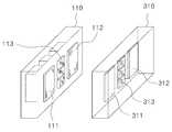
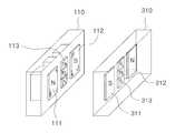
도 1은 본 발명에 의한 마그네틱 커넥팅 장치를 나타낸 개념도로서, 마그네틱 커넥팅 장치는 전원공급기(100)와 외부기기(300)에 각각 적용될 수 있다.1 is a conceptual view showing a magnetic connecting device according to the present invention, the magnetic connecting device may be applied to the
전원공급기(100)는 입력된 직류전원을 출력하거나 또는 외부로부터 입력된 상용 교류전원을 필요한 직류전원으로 변환하여 접속된 외부기기(300)로 공급하는 어댑터가 될 수 있으며, 외부기기(300)는 모바일단말기(휴대폰, PDA, 스마트폰 등)와 노트북, 컴퓨터 주변기기 등과 같은 직류전원을 공급받는 소용량 기기나, 대용량 교류 또는 직류전원을 공급받는 UPS기기, 전기자동차, 전기자전거 및 전기스쿠터 등이 될 수 있다.The
상기 전원공급기(100)와 외부기기(300)는 각각의 마그네틱 커넥터(110, 310)를 통해 전기적으로 연결될 수 있다. 이하, 설명의 편의상 전원공급기(100)의 커넥터(110)를 메인커넥터라 하고, 외부기기(300)의 커넥터(310)를 외부커넥터라 한다.The
상기 전원공급기(100)의 메인커넥터(110)와 외부기기(300)의 외부커넥터(310)는 도시된 바와 같이 동일한 구조 또는 서로 구조적으로 대응되는 요철 형상으로 형성될 수 있다. 상기 메인커넥터(110)와 외부커넥터(310)가 동일한 구조로 구성될 경우 상기 전원단자(111, 112)의 외측 일단과 통신단자(113)의 외측 일단은 동일한 수평면에 위치될 수 있다. 전원공급기(100)의 메인커넥터(110)와 외부기기(300)의 외부커넥터(310)는 서로 물리적으로 매칭 가능한 구조로 이루어질 수 있다.The
전원공급기(100)는 메인커넥터(110) 및 제어부(130)를 포함하며, 메인커넥터(110)는 제1 전원단자(111), 제2 전원단자(112), 및 통신단자(113)를 포함할 수 있다.The
외부기기(300)는 외부커넥터(310)를 포함하며, 외부커넥터(310)는 제1 전원단자(311), 제2 전원단자(312), 및 통신단자(313)를 포함할 수 있다. 복수의 전원단자(311, 312)는 전원공급기(100)의 전원단자(111, 112)와 자기적으로 각각 결합되며 전원을 전원공급기(100)로부터 전달받는다. 통신단자(313)는 복수의 전원단자(311, 312)에 인접하여 배치되어 전원공급기(100)의 통신단자(113)와 결합되며, 전원공급기(100)의 결합시 데이터가 송수신되는 적어도 하나 이상으로 구성될 수 있다. 도 1에서는 통신단자(113)가 3개로 도시되었지만 필요에 따라 가감될 수 있고, 그 배치 위치와 형태도 가변될 수 있다.The
상기에서 전원공급기(100)와 외부기기(300)가 전기적으로 연결될 경우 전원공급기(100)의 제어부(130)와 외부기기(300)는 미리 설정된 통신을 수행하도록 구성될 수 있다. 만일, 전원공급기(100)의 전원이 외부기기(300)로 공급되기 전이라면 외부기기(300)는 전원공급기(100)로부터 전달된 통신신호에 의해 구동되어 전원공급기(100)와 통신을 수행할 수 있다.When the
전원공급기(100)의 제1 전원단자(111)는 외부기기(300)의 제1 전원단자(311)와 자기적으로 결합되며, 외부기기(300)의 결합시 공급된 전원(DC+ 또는 AC1)을 외부기기(300)로 전달한다. 제2 전원단자(112)는 제1 전원단자(111)와 이격되어 설치되며, 외부기기(300)의 결합시 공급된 전원(DC- 또는 AC2)을 외부기기(300)의 제2 전원단자(312)로 전달한다. 여기서, 제1 전원단자(111)와 제2 전원단자(112)는 외부기기(300)의 외부커넥터(310)와의 방향성을 위하여 서로 다른 극성으로 형성되는 영구자석, 강자성체 및 상자성체 중 어느 하나가 될 수 있다. 예컨대, 제1 전원단자(111)가 N극이면 제2 전원단자(112)는 S극일 수 있다.The
통신단자(113)는 복수의 전원단자(111, 112)에 인접하여 배치되거나 복수의 전원단자(111, 112) 사이에 배치되어 외부기기(300)의 통신단자(313)와 접촉되며, 외부기기(300)의 결합시 데이터가 송수신된다. 상기 통신단자(113)는 영구자석, 강자성체 및 상자성체 중 어느 하나로 구성될 수 있다. 통신단자(113)는 데이터단자(D+, D-)와 신호단자(S) 및 접지단자(GND) 중 적어도 어느 하나를 포함할 수 있다.The
제어부(130)는 외부기기(300)의 결합시에 통신단자(113)를 통해 외부기기(300)의 연결 여부를 확인한 후 상기 전원단자(111, 112)를 통한 외부기기(300)로의 전원공급 여부를 제어할 수 있다. 즉, 제어부(130)는 외부기기(300)의 결합시에 외부기기(300)로부터 읽어온 식별정보와 미리 설정된 식별정보를 상호 비교하여 전원공급 여부를 결정하게 된다.The
한편, 제1 전원단자(111) 또는/및 제2 전원단자(112)의 주변에 설치되어 제1 전원단자(111) 또는/및 제2 전원단자(112)의 자기력을 강화시키기 위한 보조마그네트를 더 포함할 수 있다.On the other hand, the auxiliary magnet for strengthening the magnetic force of the
이와 같이 전원단자(111, 112)의 주변에 보조마그네트가 설치될 경우에는 전원단자(111, 112)가 마그네트가 아니라 비자성체로 구성될 수도 있다.When the auxiliary magnets are installed around the
도 2 내지 도 7은 메인커넥터와 외부커넥터의 다양한 구조를 나타낸 것으로, 메인커넥터(110)는 도 2에서와 같이 사각형 단면을 갖도록 구성될 수 있고, 도 7과 같이 원형 단면을 갖도록 구성될 수도 있다. 도 2 내지 도 6에서는 통신단자(113)가 복수의 전원단자(111, 112) 사이에 배치되어 있으며, 도 7에서는 통신단자(113)가 복수의 전원단자(111, 112)의 주변에 각각 배치되어 있다.2 to 7 illustrate various structures of the main connector and the external connector, the
또한, 메인커넥터(110)와 외부커넥터(310)는 일반적인 커넥터 형상이 아니라 플레이트 상에 전원단자(111,112)(311,312)와 통신단자(113)(313)가 각각 형성된 판 형상일 수도 있다.In addition, the
도 2에서와 같이 메인커넥터(110)의 제1 전원단자(111)와 제2 전원단자(112)는 영구자석, 강자성체 또는 상자성체로 구성되고, 통신단자(113)는 비자성체나 상자성체로 구성된 경우를 나타내었다. 도 2에서와 같이 메인커넥터(110)의 각 단자(111~113)는 표면으로부터 다소 돌출될 수 있으며, 각 단자(111~113)의 일단은 동일 수평면에 위치될 수 있다. 그리고, 외부커넥터(310)의 각 단자(311~313)는 표면으로부터 다소 매몰될 수 있는 데, 메인커넥터(110)의 돌출 높이는 외부커넥터(310)의 매몰 깊이와 동일하거나 더 커야 한다.2, the first
도 3에서와 같이 메인커넥터(110)의 제1 전원단자(111)와 제2 전원단자(112)는 비자성체나 상자성체로 구성되고, 통신단자(113)는 영구자석, 강자성체 또는 상자성체로 구성된 경우를 나타내었다.As shown in FIG. 3, when the
도 4의 경우에는 메인커넥터(110)의 제1 전원단자(111)와 제2 전원단자(112) 및 통신단자(113)가 모두 영구자석, 강자성체 및 상자성체 중 적어도 어느 하나로 구성된 경우를 도시하였다. 본 발명에 기재된 마그네트는 영구자석, 강자성체 및 상자성체 중 어느 하나를 의미한다. 이와 같이 모든 단자(111~113)를 마그네트로 구성할 경우에는 N극과 S극을 교대로 형성하는 것이 아니라 N극과 S극을 반으로 나누어서 일괄 형성하는 것이 자기력과 방향성을 위해 유리할 수 있다.4 illustrates a case in which the
여기서, 메인커넥터(110)와 자기적으로 결합되는 외부커넥터(310)의 각 단자(311~313)는 도 2 내지 도 4에 도시된 바와 같이 메인커넥터(110)의 각 단자(111~113)에 대응되는 자극으로 형성될 수 있다.Here, each terminal 311 ˜ 313 of the
또한, 외부커넥터(310)는 도 5에 도시된 바와 같이 영구자석이 아니라 강자성체 또는 상자성체로도 구성될 수 있다. 즉, 메인커넥터(110)의 단자(111~113)가 영구자석일 경우에도 외부커넥터(310)의 각 단자(311~313)는 강자성체 또는 상자성체로 구성될 수 있다. 중요한 것은 메인커넥터(110)의 각 단자(111~113)와 외부커넥터(310)의 각 단자(311~313) 중 적어도 어느 하나가 영구자석이면 된다는 것이다.In addition, the
도 6은 메인커넥터(110)와 외부커넥터(310) 간의 장착 방향성을 위하여, 메인커넥터(110)의 일정 위치에 돌기(119)가 형성된 것을 도시하였다. 외부커넥터(310)에는 돌기(119)에 대응되는 위치에 요홈(319)이 형성된다. 돌기(119)와 요홈(319)은 필요에 따라 다양한 형태나 개수로 형성될 수 있다. 메인커넥터(110)와 외부커넥터(310)에 돌기(119)와 요홈(319)이 각각 형성되어 있을 경우에는 메인커넥터(110)의 모든 단자(111~113)가 동일한 자극(N극 또는 S극)으로 형성되어도 무방하다. 이때 외부커넥터(310)는 영구자석이 아니라 강자성체 또는 상자성체로 구성되어도 무방하다.FIG. 6 illustrates that the
도 7의 경우에는 메인커넥터가 원형인 경우를 나타낸 것으로, 이 경우에도 제1 전원단자(111)와 제2 전원단자(112)는 서로 다른 극성으로 형성된다.In FIG. 7, the main connector has a circular shape. In this case, the first
상기에서 전원공급기(100)와 외부기기(300)와의 통신 방식은, SCI(Serial Communication Interface) 방식, CAN(Controller Area Network) 방식, 및 PLC(Power Line Communication) 방식 중 적어도 어느 하나일 수 있으며, SCI 방식은 EEPROM통신, RS232, RS422, RS485, 및 I2C 방식 등이 있을 수 있다. 상기 전원공급기(100)와 외부기기(300)와의 통신 방식에 따라 커넥터(110, 310)의 구조와 단자(111~113)의 수 및 단자의 배치 형태 등이 결정될 것이다.The communication method between the
즉, 메인커넥터(110)는 필요에 따라 판 형상이나 사각이나 다각형, 원형 및 타원형 중 적어도 어느 하나의 형태를 가질 수 있으며, 사이즈도 다양하게 가변될 수 있음은 당연하다. 물론, 외부기기(300)의 외부커넥터(310)도 전원공급기(100)의 메인커넥터(110)에 대응되는 형상을 가질 것이다.That is, the
한편, 본 발명에서는 메인커넥터(110)와 외부커넥터(310)를 면접촉 방식으로 도시하였는데, 각 단자의 접촉성과 설계 여유도를 향상시키기 위해 제1 전원단자(111)와 제2 전원단자(112) 및 통신단자(113)의 내측에 소정의 탄성체(미 도시됨)를 설치할 수도 있다. 탄성체는 스프링이나 고무 등이 될 수 있다.Meanwhile, in the present invention, the
물론, 외부커넥터(310)의 각 단자(311, 312, 313)에도 탄성체가 설치될 수 있으며, 두 커넥터(110, 310)에 모두 탄성체가 설치될 수도 있다. 메인커넥터(110)에 탄성체가 설치될 경우 각 단자(111, 112, 113)는 외부로 돌출되도록 구성되고, 외부커넥터(310)의 각 단자(311, 312, 313)는 홈에 다소 삽입되는 형태가 될 것이다.Of course, an elastic body may be installed at each terminal 311, 312, 313 of the
도 8은 본 발명의 실시예에 의한 마그네틱 커넥팅 장치를 나타낸 도면으로서, 마그네틱 커넥팅 장치는 전원공급기(100)와 외부기기(300)에 각각 적용될 수 있다.8 is a view showing a magnetic connecting device according to an embodiment of the present invention, the magnetic connecting device may be applied to the
전원공급기(100)는 메인커넥터(110) 및 제어부(130)를 포함하며, 메인커넥터(110)는 제1 전원단자(111), 제2 전원단자(112), 및 통신단자(113)를 포함할 수 있다.The
외부기기(300)는 외부커넥터(310)와 통신제어부(350)를 포함하며, 외부커넥터(310)는 제1 전원단자(311), 제2 전원단자(312), 및 통신단자(313)를 포함할 수 있다. 복수의 전원단자(311, 312)는 전원공급기(100)의 메인커넥터(110)와 결합되며 전원을 전원공급기(100)로부터 전달받고, 통신단자(313)는 복수의 전원단자(311, 312)에 인접하여 배치되어 전원공급기(100)의 커넥터(110)와 자기적으로 결합되며, 전원공급기의 결합시 데이터가 송수신되는 적어도 하나 이상으로 구성될 수 있다. 통신제어부(350)는 전원공급기(100)의 결합시에 통신단자(313)를 통해 식별정보(Identification)가 요청되면 미리 저장된 식별정보를 전원공급기(100)로 전달하도록 구성되어 있다.The
즉, 전원공급기(100)와 외부기기(300)가 전기적으로 연결될 경우 전원공급기(100)의 제어부(130)와 외부기기(300)의 통신제어부(350)는 미리 설정된 통신을 수행하도록 구성되어 있다. 만일, 전원공급기(100)의 전원이 외부기기(300)로 공급되기 전이라면 외부기기(300)의 통신제어부(350)는 내장된 배터리(390)에 의해 구동되어 전원공급기(100)와 통신을 수행할 수 있다. 여기에서, 외부기기(300)는 내장된 배터리가 없을 경우에는 전원공급기(100)로부터 전달된 통신신호에 의해 구동되어 전원공급기(100)와 통신을 수행할 수 있다.That is, when the
이하, 전원공급기(100)와 그 메인커넥터(110)를 중심으로 본 발명을 설명하고자 한다.Hereinafter, the present invention will be described based on the
전원공급기(100)의 제1 전원단자(111)는 외부기기(300)의 외부커넥터(310)와 자기적으로 결합되며, 외부기기(300)의 결합시 공급된 전원(DC+ 또는 AC1)을 외부기기(300)로 전달한다. 제2 전원단자(112)는 제1 전원단자(111)와 일정간격 이격되어 설치되며, 외부기기(300)의 결합시 공급된 전원(DC- 또는 AC2)을 외부기기(300)로 전달한다.The
통신단자(113)는 복수의 전원단자(111, 112)에 인접하여 배치되거나 복수의 전원단자(111, 112) 사이에 배치되어 외부기기(300)의 외부커넥터(310)와 접촉되며, 외부기기(300)의 결합시 데이터가 송수신된다. 상기 통신단자(113)는 영구자석, 강자성체 및 상자성체 중 어느 하나로 구성될 수 있다. 통신단자(113)는 데이터단자(D+, D-)와 신호단자(S) 및 접지단자(GND) 중 적어도 어느 하나를 포함할 수 있다.The
제어부(130)는 외부기기(300)의 결합시에 통신단자(113)를 통해 외부기기(300)의 연결 여부를 확인한 후 상기 전원단자(111, 112)를 통한 외부기기(300)로의 전원공급 여부를 제어하게 된다. 즉, 제어부(130)는 외부기기(300)의 결합시에 외부기기(300)로부터 읽어온 식별정보와 미리 설정된 식별정보를 상호 비교하여 전원공급 여부를 결정하게 된다. 상기에서 식별정보는 제품정보나 고유번호 등이 될 수 있다.The
따라서, 제어부(130)는 외부기기(300)가 전원공급기(100)에 연결될 경우에만 전원이 제1 전원단자(111)와 제2 전원단자(112)로 출력되도록 한다. 이와 같이 구성하는 가장 큰 이유는 메인커넥터(110)에 이물질이 접촉될 경우에 감전 등의 안전사고로부터 안전성을 보장할 수 있기 때문이다.Therefore, the
도 9는 본 발명의 일실시예에 의한 마그네틱 커넥터가 적용된 전원공급기의 세부 구조를 나타낸 도면으로서, 전원공급기(100)는 안정화부(101), 평활부(102), 변압부(103), 정류부(104), 스위치부(105), 메인커넥터(110) 및 제어부(130)를 포함할 수 있다. 전원공급기(100)는 도 8과 같이 외부기기(300)와 연결될 수 있다.9 is a view showing a detailed structure of the power supply to which the magnetic connector according to an embodiment of the present invention is applied, the
안정화부(101)는 외부로부터 입력되는 상용 교류전압, 예컨대 AC 110V 또는 AC 220V를 대략 1.414배로 승압시키거나 입력된 교류전압을 안정화시키도록 구성되어 있다.The
평활부(102)는 안정화부(101)에서 출력되는 전압을 평활시켜서 직류전압에 가까운 전압을 출력한다. 즉, 평활부(102)는 안정화부(101)에서 출력되는 전압에 포함된 리플(ripple)을 최소화시켜 리플 노이즈를 감소시킨다.The smoothing
변압부(103)는 평활부(102)에서 출력되는 전압을 필요한 전압 레벨로 강하시켜서 출력한다. 변압부(103)는 1차 권선과 2차 권선으로 구성된다. 1차 권선과 2차 권선의 수를 적절히 조정함으로써 출력단에 나타나는 노이즈를 감소시킬 수가 있다.The
정류부(104)는 변압부(103)의 2차 권선에서 출력되는 전압을 정류하여 메인커넥터(110) 측으로 직류전압을 출력한다. 변압부(103)의 2차측에 발생하는 전압은 구형파에 가깝기 때문에 정류부(104)는 이를 정류하여 메인커넥터(110)를 통해 출력되는 전압을 직류전압으로 만들어준다. 정류부(104)는 인덕터 코일(inductor coil)을 사용하여 리플 노이즈를 최소화시킴에 따라 출력전압을 보다 직류전압에 가깝도록 만들 수 있다.The
스위치부(105)는 직류출력단인 정류부(104)와 메인커넥터(110)의 전원단자 사이에 설치되어 소정의 제어신호에 따라 스위칭되어 정류부(104)로부터 입력되는 전원을 메인커넥터(110)의 전원단자로 출력하게 된다. 물론, 스위치부(105)는 제어신호에 의해 스위칭될 수도 있지만, 사용자에 의한 선택에 따라 스위칭(on/off)되도록 구성될 수도 있다.The
메인커넥터(110)는 외부기기(300)의 외부커넥터(310)와 자기적으로 결합되어 외부기기(300)의 외부커넥터(310)로 데이터의 송수신과 동작전원을 전달하게 된다. 메인커넥터(110)는 제1 전원단자(111), 제2 전원단자(112), 및 통신단자(113)를 포함하여 이루어져 있다. 즉, 메인커넥터(110)는 외부기기(300)의 외부커넥터(310)와 자기적으로 결합되며, 외부기기(300)의 결합시 공급된 전원을 외부기기(300)로 전달하는 제1 전원단자(111)와, 상기 제1 전원단자(111)와 일정 간격 이격되어 설치되며, 외부기기(300)의 결합시 공급된 전원을 외부기기(300)로 전달하는 제2 전원단자(112), 및 복수의 전원단자(111, 112) 사이에 배치되어 외부기기(300)의 외부커넥터(310)와 접촉되며 외부기기(300)의 결합시 데이터가 송수신되는 통신단자(113)로 구성될 수 있다. 여기서, 제1 전원단자(111)와 제2 전원단자(112)는 외부기기(300)의 외부커넥터(310)와의 방향성을 위하여 서로 다른 극성의 마그네트로 형성될 수 있다. 통신단자(113)도 필요에 따라 마그네트로 구성될 수 있다.The
제어부(130)는 외부기기(300)의 결합시에 통신단자(113)를 통해 외부기기(300)의 식별정보를 확인한 후 상기 전원단자(111, 112)를 통한 외부기기(300)로의 전원공급 여부를 제어하게 된다. 구체적으로, 제어부(130)는 도시된 바와 같이 통신제어부(131)와 전원제어부(135)로 구성될 수 있다. 즉, 통신제어부(131)는 메인커넥터(110)에 외부기기(300)의 결합시에 외부기기(300)로 식별정보를 요청하고, 요청 명령에 따라 외부기기(300)의 통신제어부(350)로부터 읽어온 식별정보를 미리 설정된 식별정보와 상호 비교하게 된다. 전원제어부(135)는 통신제어부(131)의 비교 결과에 따라 스위치부(105)를 제어하여 외부기기(300)로의 전원공급 여부를 결정하게 된다. 따라서, 제어부(130)는 설정된 외부기기(300)가 전원공급기(100)에 연결될 경우에만 전원이 제1 전원단자(111)와 제2 전원단자(112)로 출력되도록 한다.The
이와 같이 본 발명에서는 전원공급기(100)와 외부기기(300)가 자기적으로 연결될 경우 외부기기(300)로 전원을 공급하기 전에 전원공급기(100)의 제어부(130)와 외부기기(300)의 통신제어부(350)는 미리 설정된 통신을 수행하도록 구성되어 있다. 만일, 전원공급기(100)의 전원이 외부기기(300)로 공급되기 전이라면 외부기기(300)의 통신제어부(350)는 내장된 배터리(390) 또는 통신단자(113)를 통해 입력된 신호에 의해 구동되어 전원공급기(100)와 통신을 수행하게 될 것이다.As such, in the present invention, when the
도 10은 본 발명의 다른 실시예에 의한 마그네틱 커넥터가 적용된 전원공급기의 세부 구조를 나타낸 도면으로서, 전원공급기(100)는 안정화부(101), 평활부(102), 변압부(103), 정류부(104), 스위치부(105), 메인커넥터(110) 및 제어부(130)를 포함할 수 있다. 전원공급기(100)는 도 8과 같이 외부기기(300)와 연결될 수 있다.10 is a view showing a detailed structure of the power supply to which the magnetic connector according to another embodiment of the present invention, the
도 10은 도 9와 다르게 메인커넥터 측으로 직류전원이 아니라 교류전원이 인가되는 것에 큰 특징이 있으며, 이를 중심으로 간단하게 살펴본다.FIG. 10 has a big feature that AC power is applied to the main connector side instead of DC power, differently from FIG. 9.
즉, 정류부(104)는 변압부(103)의 2차 권선에서 출력되는 전압을 정류하여 제어부(130) 측으로 출력한다.That is, the
스위치부(105)는 교류입력단과 메인커넥터(110) 사이에 설치되어 소정의 제어신호에 따라 스위칭되어 외부로부터 입력된 교류전원을 메인커넥터(110)로 출력하게 된다.The
메인커넥터(110)는 외부기기(300)의 외부커넥터(310)와 자기적으로 결합되어 외부기기(300)의 외부커넥터(310)로 데이터의 송수신과 동작전원을 전달하게 된다. 메인커넥터(110)는 제1 전원단자(111), 제2 전원단자(112), 및 통신단자(113)를 포함하여 이루어져 있다.The
제어부(130)는 외부기기(300)의 결합시에 통신단자(113)를 통해 외부기기(300)의 식별정보를 확인한 후 상기 전원단자(111, 112)를 통한 외부기기(300)로의 전원공급 여부를 제어하게 된다. 구체적으로, 제어부(130)는 도시된 바와 같이 통신제어부(131)와 전원제어부(135)로 구성될 수 있다. 즉, 통신제어부(131)는 메인커넥터(110)에 외부기기(300)의 결합시에 외부기기(300)로 식별정보를 요청하고, 요청 명령에 따라 외부기기(300)의 통신제어부(350)로부터 읽어온 식별정보를 미리 설정된 식별정보와 상호 비교하게 된다. 전원제어부(135)는 통신제어부(131)의 비교 결과에 따라 스위치부(105)를 제어하여 외부기기(300)로의 전원공급 여부를 결정하게 된다. 따라서, 제어부(130)는 설정된 외부기기(300)가 전원공급기(100)에 연결될 경우에만 입력된 교류전원이 제1 전원단자(111)와 제2 전원단자(112)로 출력되도록 한다.The
도 11은 본 발명의 또다른 실시예에 의한 마그네틱 커넥터가 적용된 전원공급기의 세부 구조를 나타낸 도면으로서, 전원공급기(100)는 안정화부(101), 평활부(102), 변압부(103), 정류부(104), 스위치부(105), 메인커넥터(110), 코일(121, 122) 및 제어부(130)를 포함할 수 있다. 전원공급기(100)는 도 8과 같이 외부기기(300)와 연결될 수 있다.11 is a view illustrating a detailed structure of a power supply to which a magnetic connector is applied according to another embodiment of the present invention, wherein the
도 11은 도 9와 다르게 전원단자(111, 112)에 코일이 권선되어 있어 외부에서 인가되는 전류방향에 따라 전원단자와 동일한 극성 또는 다른 극성을 가질 수 있다.In FIG. 11, unlike FIG. 9, a coil is wound around
즉, 메인커넥터(110)는 외부기기(300)의 외부커넥터(310)와 자기적으로 결합되어 외부기기(300)의 외부커넥터(310)로 데이터의 송수신과 동작전원을 전달하게 된다. 메인커넥터(110)는 제1 전원단자(111), 제2 전원단자(112), 및 통신단자(113)를 포함하여 이루어져 있다.In other words, the
제어부(130)는 외부기기(300)의 결합시에 통신단자(113)를 통해 외부기기(300)의 식별정보를 확인한 후 상기 전원단자(111, 112)를 통한 외부기기(300)로의 전원공급 여부를 제어하게 된다. 구체적으로, 제어부(130)는 도시된 바와 같이 통신제어부(131)와 전원제어부(135)로 구성될 수 있다. 즉, 통신제어부(131)는 메인커넥터(110)에 외부기기(300)의 결합시에 외부기기(300)로 식별정보를 요청하고, 요청 명령에 따라 외부기기(300)의 통신제어부(350)로부터 읽어온 식별정보를 미리 설정된 식별정보와 상호 비교하게 된다. 전원제어부(135)는 통신제어부(131)의 비교 결과 외부기기의 식별정보가 미리 저장된 식별정보와 동일할 경우 스위치부(105)를 온시켜 외부기기(300)로 동작전원을 공급하게 된다.The
전원제어부(135)는 외부기기(300)의 식별정보가 미리 저장된 식별정보와 다를 경우에는 스위치부(105)를 오프시킴과 아울러 전원단자(111, 112)에 각각 권선된 코일(121, 122)로 전류를 인가하여 메인커넥터(110)의 전원단자(111, 112)가 외부기기(300)의 전원단자(311, 312)와 동일한 극성으로 자기화시킴으로써, 외부기기(300)의 외부커넥터(310)를 강제 분리시킬 수 있다. 즉, 코일(121, 122)은 전원단자(111, 112)에 권선되어 인가되는 전류에 따라 자기장을 발생하여 전원단자(111, 112)의 자기력을 약화시키는 전자석으로 동작된다. 코일(121, 122)에는 전원단자(111, 112)의 자기력을 약화시키는 방향으로 자기장이 발생되도록 전류가 인가된다.When the identification information of the
한편, 제어부(130)는 외부에서 과전류(OCP; over current protection), 과전압(OVP; over voltage protection) 또는 과온도(OTP; over temperature protection)에 대한 신호가 입력될 경우에도 전원단자(111, 112)에 각각 권선된 코일(121, 122)로 전류를 인가하여 메인커넥터(110)의 전원단자(111, 112)가 외부기기(300)의 전원단자(311, 312)와 동일한 극성으로 자기화시킴으로써, 외부기기(300)의 외부커넥터(310)를 강제로 분리시킬 수도 있다.On the other hand, the
따라서, 제어부(130)는 설정된 외부기기(300)가 전원공급기(100)에 연결될 경우에만 입력된 직류전원 또는 교류전원이 제1 전원단자(111)와 제2 전원단자(112)로 출력되도록 한다. 도 9 및 도 10의 메인커넥터(110)에서도 전원단자(111, 112)와 통신단자(113)는 마그네트 또는 전자석 중 적어도 어느 하나로 구성될 수 있다.Therefore, the
도 12는 본 발명의 또다른 실시예에 의한 마그네틱 커넥터가 적용된 전원공급기를 나타낸 개념도로서, 전원공급기(100)는 메인커넥터(110)와 제어부(130) 및 USB커넥터(150)를 포함할 수 있다. 전원공급기(100)는 도 8과 같이 외부기기(300)와 연결될 수 있다.12 is a conceptual diagram illustrating a power supply to which a magnetic connector is applied according to another embodiment of the present invention, the
메인커넥터(110)는, 외부기기(300)의 외부커넥터(310)와 자기적으로 결합되며 전원을 외부기기(300)로 전달하는 복수의 전원단자(111, 112)와, 상기 복수의 전원단자(111, 112) 사이에 배치되어 외부기기(300)의 외부커넥터(310)와 접촉되며 외부기기(300)의 결합시 데이터가 송수신되는 적어도 하나의 통신단자(113)를 구비한다.The
제어부(130)는 외부기기(300)의 결합시에 상기 통신단자(113)를 통해 외부기기(300)의 식별정보를 확인한 후 상기 전원단자(111, 112)를 통한 외부기기(300)로의 전원공급 여부를 제어하게 된다. 여기서, 제어부(130)는 메인커넥터(110)의 내부에 내장되어 일체로 형성되는 것으로 나타내었으나, 필요에 따라 메인커넥터(110)의 외부에 설치될 수도 있다.The
USB커넥터(150)는 메인커넥터(110)의 일측에 케이블(140)을 통해 연장되며, 외부(예를 들어, 컴퓨터)로부터 입력된 직류전원(DC+, DC-)과 데이터(D+, D-)를 메인커넥터(110)로 전달하게 된다.The
이와 같이 도 12의 전원공급기(100)에서는 메인커넥터(110)가 외부기기(300)의 외부커넥터(310)와 결합되면, 컴퓨터나 어댑터 등으로부터 입력되는 직류전원은 USB커넥터(150)와 메인커넥터(110)를 통해 외부기기(300)로 전달된다. 전원공급기(100)를 USB커넥터 타입의 휴대용으로 제작함에 따라 사용의 편의성을 향상시킬 수 있다.As described above, in the
이와 같이 구성된 메인커넥터를 특정 위치에 거치하거나 메인커넥터에 외부기기를 올려놓거나 또는 메인커넥터를 외부기기의 외부커넥터와 단순 결합하는 형태를 가지는 등의 응용 가능한 다양한 형태를 가질 수 있다. 이는 일반적인 무선전력전송기기에 비해 상대적으로 매우 간단하고 적은 비용으로 구성할 수 있고, 사용에 있어서도 매우 간편하고 편리한 구조를 갖게 된다. 또한, 에너지전달 측면에서도 효율의 저하없는 전력 전달의 형태를 갖는다.The main connector configured as described above may be mounted in a specific position, put an external device on the main connector, or have a form in which the main connector is simply combined with an external device of the external device. This is relatively simple compared to the general wireless power transmission device and can be configured at a low cost, and also has a very simple and convenient structure in use. In addition, in terms of energy transfer, it has a form of power transfer without deterioration of efficiency.
상기의 본 발명은 바람직한 실시예를 중심으로 살펴보았으며, 본 발명이 속하는 기술분야에서 통상의 지식을 가진 자는 본 발명의 본질적 기술 범위 내에서 상기 본 발명의 상세한 설명과 다른 형태의 실시예들을 구현할 수 있을 것이다. 여기서 본 발명의 본질적 기술범위는 특허청구범위에 나타나 있으며, 그와 동등한 범위 내에 있는 모든 차이점은 본 발명에 포함된 것으로 해석되어야 할 것이다.
The present invention has been described with reference to the preferred embodiments, and those skilled in the art to which the present invention pertains to the detailed description of the present invention and other forms of embodiments within the essential technical scope of the present invention. Could be. Here, the essential technical scope of the present invention is shown in the claims, and all differences within the equivalent range will be construed as being included in the present invention.
100: 전원공급기 101: 안정화부
102: 평활부 103: 변환부
104: 정류부 105: 스위치부
110: 메인커넥터 111,112: 전원단자
113: 통신단자 121,122: 전자석(코일)
130: 제어부 131: 통신제어부
135: 전원제어부 150: USB커넥터
300: 외부기기 310: 외부커넥터
350: 통신제어부 390: 배터리100: power supply 101: stabilization unit
102: smoothing unit 103: conversion unit
104: rectifier 105: switch
110:
113: communication terminal 121,122: electromagnet (coil)
130: control unit 131: communication control unit
135: power control unit 150: USB connector
300: external device 310: external connector
350: communication control unit 390: battery
Claims (40)
Translated fromKorean상기 복수의 전원단자에 인접하여 배치되어 상기 외부기기의 커넥터와 접촉되고 외부기기의 결합시 데이터가 송수신되는 적어도 하나의 통신단자;를 포함하는 마그네틱 커넥팅 장치.A plurality of power terminals magnetically coupled to the connector of the external device and transferring power to the external device; And
And at least one communication terminal disposed adjacent to the plurality of power terminals to be in contact with a connector of the external device and to transmit and receive data when the external device is coupled.
상기 복수의 전원단자는 서로 다른 극성의 자성체로 형성되는 마그네틱 커넥팅 장치.The method according to claim 1,
And a plurality of power terminals are formed of magnetic materials having different polarities.
상기 전원단자는 영구자석, 강자성체 및 상자성체 중 어느 하나로 구성되는 마그네틱 커넥팅 장치.The method according to claim 1,
The power terminal is a magnetic connecting device consisting of any one of a permanent magnet, ferromagnetic and paramagnetic.
상기 전원단자는 코일이 권선된 전자석으로 구성되는 마그네틱 커넥팅 장치.The method according to claim 1,
The power terminal is a magnetic connecting device consisting of an electromagnet wound around the coil.
상기 전원단자는 직류전원 또는 교류전원을 외부기기로 전달하는 마그네틱 커넥팅 장치.The method according to claim 1,
The power terminal is a magnetic connecting device for transmitting a DC power or AC power to an external device.
상기 통신단자는 영구자석, 강자성체 및 상자성체 중 어느 하나로 구성되는 마그네틱 커넥팅 장치.The method according to claim 1,
The communication terminal is a magnetic connecting device consisting of any one of a permanent magnet, a ferromagnetic material and a paramagnetic material.
상기 전원단자의 외측 일단과 통신단자의 외측 일단은 동일한 수평면에 위치되는 마그네틱 커넥팅 장치.The method according to claim 1,
And an outer end of the power terminal and an outer end of the communication terminal are located on the same horizontal plane.
상기 외부기기의 결합시에 상기 통신단자를 통해 외부기기의 연결 여부를 확인한 후 상기 전원단자를 통한 외부기기로의 전원공급 여부를 제어하는 제어부;를 더 포함하는 마그네틱 커넥팅 장치.The method according to claim 1,
And a control unit which controls whether to supply power to an external device through the power terminal after checking whether the external device is connected through the communication terminal when the external device is coupled.
상기 제어부는 외부기기의 결합시에 외부기기로부터 읽어온 식별정보와 미리 설정된 식별정보를 상호 비교하여 전원공급 여부를 결정하는 마그네틱 커넥팅 장치.The method according to claim 8,
The control unit is a magnetic connecting device for determining whether the power supply by comparing the identification information read from the external device and the predetermined identification information when the external device is combined.
상기 제어부는, 외부기기의 결합시에 외부기기로 식별정보를 요청하고, 외부기기로부터 읽어온 식별정보를 미리 설정된 식별정보와 상호 비교하는 통신제어부; 및 상기 통신제어부의 비교 결과에 따라 스위치부를 제어하여 외부기기로의 전원공급 여부를 제어하는 전원제어부;를 포함하는 마그네틱 커넥팅 장치.The method according to claim 8,
The control unit may include: a communication control unit for requesting identification information from an external device when the external device is combined, and comparing the identification information read from the external device with preset identification information; And a power control unit controlling a switch unit according to a comparison result of the communication control unit to control whether or not power is supplied to an external device.
상기 스위치부는 직류출력단과 전원단자 사이에 배치되는 마그네틱 커넥팅 장치.The method of claim 10,
The switch unit is a magnetic connecting device disposed between the DC output terminal and the power terminal.
상기 스위치부는 교류출력단과 전원단자 사이에 배치되는 마그네틱 커넥팅 장치.The method of claim 10,
The switch unit is a magnetic connecting device disposed between the AC output terminal and the power terminal.
상기 통신단자와 외부기기와의 통신 방식은, SCI(Serial Communication Interface), CAN(Controller Area Network), 및 PLC(Power Line Communication) 중 적어도 어느 하나인 마그네틱 커넥팅 장치.
The method according to claim 1,
The communication method between the communication terminal and an external device is at least one of a serial communication interface (SCI), a controller area network (CAN), and a power line communication (PLC).
상기 복수의 전원단자에 인접하여 배치되어 외부기기의 커넥터와 자기적으로 결합되며, 외부기기의 결합시 데이터가 송수신되는 적어도 하나의 통신단자;를 포함하는 마그네틱 커넥팅 장치.A plurality of power terminals coupled to a connector of the external device and transferring power to the external device; And
And at least one communication terminal disposed adjacent to the plurality of power terminals and magnetically coupled to a connector of an external device, wherein data is transmitted and received when the external device is coupled.
상기 통신단자는 영구자석, 강자성체 및 상자성체 중 어느 하나로 구성되는 마그네틱 커넥팅 장치.The method according to claim 14,
The communication terminal is a magnetic connecting device consisting of any one of a permanent magnet, a ferromagnetic material and a paramagnetic material.
상기 통신단자는 복수의 전원단자 사이에 배치되는 마그네틱 커넥팅 장치.The method according to claim 14,
The communication terminal is a magnetic connecting device disposed between a plurality of power terminals.
상기 복수의 전원단자는 서로 다른 극성의 자성체로 형성되는 마그네틱 커넥팅 장치.The method according to claim 14,
And a plurality of power terminals are formed of magnetic materials having different polarities.
상기 외부기기의 결합시에 상기 통신단자를 통해 외부기기의 연결 여부를 확인한 후 상기 전원단자를 통한 외부기기로의 전원공급 여부를 제어하는 제어부;를 더 포함하는 마그네틱 커넥팅 장치.The method according to claim 14,
And a control unit which controls whether to supply power to an external device through the power terminal after checking whether the external device is connected through the communication terminal when the external device is coupled.
상기 제어부는 외부기기의 결합시에 외부기기로부터 읽어온 식별정보와 미리 설정된 식별정보를 상호 비교하여 전원공급 여부를 결정하는 마그네틱 커넥팅 장치.
19. The method of claim 18,
The control unit is a magnetic connecting device for determining whether the power supply by comparing the identification information read from the external device and the predetermined identification information when the external device is combined.
상기 복수의 전원단자에 인접하여 배치되어 상기 전원공급기의 커넥터와 접촉되고 전원공급기의 결합시 데이터가 송수신되는 적어도 하나의 통신단자;를 포함하는 마그네틱 커넥팅 장치.A plurality of power terminals magnetically coupled to the connector of the power supply and receiving power from the power supply; And
And at least one communication terminal disposed adjacent to the plurality of power terminals to be in contact with the connector of the power supply and to transmit and receive data when the power supply is coupled.
상기 복수의 전원단자는 서로 다른 극성의 자성체로 형성되는 마그네틱 커넥팅 장치.The method of claim 20,
And a plurality of power terminals are formed of magnetic materials having different polarities.
상기 전원단자는 영구자석, 강자성체 및 상자성체 중 어느 하나로 구성되는 마그네틱 커넥팅 장치.The method of claim 20,
The power terminal is a magnetic connecting device consisting of any one of a permanent magnet, ferromagnetic and paramagnetic.
상기 전원단자는 직류전원 또는 교류전원을 전원공급기로부터 전달받은 마그네틱 커넥팅 장치.The method of claim 20,
The power terminal is a magnetic connecting device that receives a DC power or AC power from a power supply.
상기 통신단자는 영구자석, 강자성체 및 상자성체 중 어느 하나로 구성되는 마그네틱 커넥팅 장치.The method of claim 20,
The communication terminal is a magnetic connecting device consisting of any one of a permanent magnet, a ferromagnetic material and a paramagnetic material.
상기 전원단자의 외측 일단과 통신단자의 외측 일단은 동일한 수평면에 위치되는 마그네틱 커넥팅 장치.The method of claim 20,
And an outer end of the power terminal and an outer end of the communication terminal are located on the same horizontal plane.
상기 전원공급기의 결합시에 상기 통신단자를 통해 식별정보가 요청되면 미리 저장된 식별정보를 전원공급기로 전달하는 통신제어부;를 더 포함하는 마그네틱 커넥팅 장치.
The method of claim 20,
And a communication control unit for transmitting previously stored identification information to a power supply when identification information is requested through the communication terminal when the power supply is coupled.
상기 복수의 전원단자에 인접하여 배치되어 전원공급기의 커넥터와 자기적으로 결합되며, 전원공급기의 결합시 데이터가 송수신되는 적어도 하나의 통신단자;를 포함하는 마그네틱 커넥팅 장치.A plurality of power terminals coupled to the connector of the power supply and receiving power from the power supply; And
And at least one communication terminal disposed adjacent to the plurality of power terminals and magnetically coupled to the connector of the power supply, wherein at least one communication terminal transmits and receives data when the power supply is coupled.
상기 통신단자는 영구자석, 강자성체 및 상자성체 중 어느 하나로 구성되는 마그네틱 커넥팅 장치.The method of claim 27,
The communication terminal is a magnetic connecting device consisting of any one of a permanent magnet, a ferromagnetic material and a paramagnetic material.
상기 통신단자는 복수의 전원단자 사이에 배치되는 마그네틱 커넥팅 장치.The method of claim 27,
The communication terminal is a magnetic connecting device disposed between a plurality of power terminals.
상기 복수의 전원단자는 서로 다른 극성의 자성체로 형성되는 마그네틱 커넥팅 장치.The method of claim 27,
And a plurality of power terminals are formed of magnetic materials having different polarities.
상기 전원공급기의 결합시에 상기 통신단자를 통해 식별정보가 요청되면 미리 저장된 식별정보를 전원공급기로 전달하는 통신제어부;를 더 포함하는 마그네틱 커넥팅 장치.
The method of claim 27,
And a communication control unit for transmitting previously stored identification information to a power supply when identification information is requested through the communication terminal when the power supply is coupled.
상기 복수의 전원단자에 인접하여 배치되어 외부기기의 커넥터와 결합되며 외부기기의 결합시 데이터가 송수신되는 적어도 하나의 통신단자; 및
상기 외부기기의 결합시에 통신단자를 통해 외부기기의 식별정보를 확인한 후 상기 전원단자를 통한 외부기기로의 전원공급 여부를 제어하는 제어부;를 포함하는 마그네틱 커넥팅 장치.A plurality of power terminals magnetically coupled to the connector of the external device and transferring power to the external device;
At least one communication terminal disposed adjacent to the plurality of power terminals and coupled to a connector of an external device, and data is transmitted and received when the external device is coupled; And
And a controller configured to control whether power is supplied to the external device through the power terminal after checking the identification information of the external device through the communication terminal when the external device is combined.
상기 전원단자는 영구자석, 강자성체 및 상자성체 중 어느 하나로 구성되는 마그네틱 커넥팅 장치.The method according to claim 32,
The power terminal is a magnetic connecting device consisting of any one of a permanent magnet, ferromagnetic and paramagnetic.
상기 전원단자에는 코일이 권선되고,
상기 제어부는 외부기기의 식별정보가 미리 설정된 정보가 아닐 경우 상기 코일로 전류를 공급하여 외부기기의 커넥터를 강제 분리시키는 마그네틱 커넥팅 장치.The method according to claim 32,
A coil is wound around the power terminal,
The control unit is a magnetic connecting device for forcibly disconnecting the connector of the external device by supplying a current to the coil when the identification information of the external device is not predetermined information.
상기 통신단자는 영구자석, 강자성체 및 상자성체 중 어느 하나로 구성되는 마그네틱 커넥팅 장치.
The method according to claim 32,
The communication terminal is a magnetic connecting device consisting of any one of a permanent magnet, a ferromagnetic material and a paramagnetic material.
상기 메인커넥터의 일측에 케이블을 통해 연장되며, 외부로부터 입력된 직류전원을 상기 메인커넥터로 전달하는 USB커넥터;를 포함하는 마그네틱 커넥팅 장치.A plurality of power terminals magnetically coupled to the connector of the external device and transferring power to the external device, and at least one disposed between the plurality of power terminals to contact the connector of the external device and transmitting / receiving data when the external device is coupled A main connector having a communication terminal; And
And a USB connector extending through a cable to one side of the main connector and transferring a DC power input from the outside to the main connector.
상기 외부기기의 결합시에 상기 통신단자를 통해 외부기기의 연결 여부를 확인한 후 상기 전원단자를 통한 외부기기로의 전원공급 여부를 제어하는 제어부;를 더 포함하는 마그네틱 커넥팅 장치.37. The method of claim 36,
And a control unit which controls whether to supply power to an external device through the power terminal after checking whether the external device is connected through the communication terminal when the external device is coupled.
상기 제어부는 메인커넥터의 내부에 내장되는 마그네틱 커넥팅 장치.37. The method of claim 36,
The control unit is a magnetic connecting device embedded in the main connector.
상기 전원단자는 영구자석, 강자성체 및 상자성체 중 어느 하나로 구성되는 마그네틱 커넥팅 장치.37. The method of claim 36,
The power terminal is a magnetic connecting device consisting of any one of a permanent magnet, ferromagnetic and paramagnetic.
상기 통신단자는 영구자석, 강자성체 및 상자성체 중 어느 하나로 구성되는 마그네틱 커넥팅 장치.37. The method of claim 36,
The communication terminal is a magnetic connecting device consisting of any one of a permanent magnet, a ferromagnetic material and a paramagnetic material.
Priority Applications (3)
| Application Number | Priority Date | Filing Date | Title |
|---|---|---|---|
| KR1020110047769AKR20120129488A (en) | 2011-05-20 | 2011-05-20 | Magnetic connecting device |
| US13/349,850US20120295451A1 (en) | 2011-05-20 | 2012-01-13 | Magnetic connecting device |
| PCT/KR2012/000337WO2012161399A1 (en) | 2011-05-20 | 2012-01-13 | Magnetic connecting device |
Applications Claiming Priority (1)
| Application Number | Priority Date | Filing Date | Title |
|---|---|---|---|
| KR1020110047769AKR20120129488A (en) | 2011-05-20 | 2011-05-20 | Magnetic connecting device |
Publications (1)
| Publication Number | Publication Date |
|---|---|
| KR20120129488Atrue KR20120129488A (en) | 2012-11-28 |
Family
ID=47175237
Family Applications (1)
| Application Number | Title | Priority Date | Filing Date |
|---|---|---|---|
| KR1020110047769ACeasedKR20120129488A (en) | 2011-05-20 | 2011-05-20 | Magnetic connecting device |
Country Status (3)
| Country | Link |
|---|---|
| US (1) | US20120295451A1 (en) |
| KR (1) | KR20120129488A (en) |
| WO (1) | WO2012161399A1 (en) |
Cited By (8)
| Publication number | Priority date | Publication date | Assignee | Title |
|---|---|---|---|---|
| WO2015002340A1 (en)* | 2013-07-03 | 2015-01-08 | (주)대한특수금속 | Data cable device having multiple connectors |
| US9006723B2 (en) | 2013-05-24 | 2015-04-14 | Samsung Display Co., Ltd. | Organic light-emitting diode (OLED) display |
| KR20170041065A (en)* | 2015-10-06 | 2017-04-14 | 엘지디스플레이 주식회사 | Connector and electronic device having therreof |
| WO2017073918A1 (en)* | 2015-10-27 | 2017-05-04 | 이동훈 | Usb flash drive |
| WO2017126925A1 (en)* | 2016-01-22 | 2017-07-27 | (주)에스피에스 | Magnetic connecting apparatus |
| CN110649671A (en)* | 2018-12-26 | 2020-01-03 | 苏州乐轩科技有限公司 | Charging station, charging system and charging method |
| KR102253555B1 (en)* | 2019-12-10 | 2021-05-20 | 주식회사 현대케피코 | Battery pack system |
| KR102676415B1 (en)* | 2023-09-27 | 2024-06-19 | 주식회사 디에스나이키 | The wireless charging device of the electric mobile rack |
Families Citing this family (96)
| Publication number | Priority date | Publication date | Assignee | Title |
|---|---|---|---|---|
| US7311526B2 (en) | 2005-09-26 | 2007-12-25 | Apple Inc. | Magnetic connector for electronic device |
| US7351066B2 (en) | 2005-09-26 | 2008-04-01 | Apple Computer, Inc. | Electromagnetic connector for electronic device |
| JP4650524B2 (en)* | 2008-06-24 | 2011-03-16 | ソニー株式会社 | COMMUNICATION DEVICE, COMMUNICATION METHOD, COMMUNICATION SYSTEM, AND COMPUTER PROGRAM |
| US9847636B2 (en) | 2012-10-03 | 2017-12-19 | Ideal Industries, Inc. | Low voltage buss system |
| EP2493029B1 (en)* | 2011-02-28 | 2013-04-03 | General Electric Company | Magnetic connector system |
| US8888500B2 (en) | 2011-06-30 | 2014-11-18 | Apple Inc. | Robust magnetic connector |
| US9065205B2 (en) | 2011-08-11 | 2015-06-23 | Apple Inc. | Connector insert having a cable crimp portion with protrusions and a receptacle having label in the front |
| US11144630B2 (en) | 2011-12-30 | 2021-10-12 | Bedrock Automation Platforms Inc. | Image capture devices for a secure industrial control system |
| US9467297B2 (en) | 2013-08-06 | 2016-10-11 | Bedrock Automation Platforms Inc. | Industrial control system redundant communications/control modules authentication |
| US11314854B2 (en) | 2011-12-30 | 2022-04-26 | Bedrock Automation Platforms Inc. | Image capture devices for a secure industrial control system |
| US9449756B2 (en) | 2013-05-02 | 2016-09-20 | Bedrock Automation Platforms Inc. | Electromagnetic connectors |
| US10834094B2 (en) | 2013-08-06 | 2020-11-10 | Bedrock Automation Platforms Inc. | Operator action authentication in an industrial control system |
| US10834820B2 (en) | 2013-08-06 | 2020-11-10 | Bedrock Automation Platforms Inc. | Industrial control system cable |
| US9437967B2 (en) | 2011-12-30 | 2016-09-06 | Bedrock Automation Platforms, Inc. | Electromagnetic connector for an industrial control system |
| US8868813B2 (en) | 2011-12-30 | 2014-10-21 | Bedrock Automation Platforms Inc. | Communications control system with a serial communications interface and a parallel communications interface |
| US9727511B2 (en) | 2011-12-30 | 2017-08-08 | Bedrock Automation Platforms Inc. | Input/output module with multi-channel switching capability |
| US9191203B2 (en) | 2013-08-06 | 2015-11-17 | Bedrock Automation Platforms Inc. | Secure industrial control system |
| US8971072B2 (en) | 2011-12-30 | 2015-03-03 | Bedrock Automation Platforms Inc. | Electromagnetic connector for an industrial control system |
| US8862802B2 (en) | 2011-12-30 | 2014-10-14 | Bedrock Automation Platforms Inc. | Switch fabric having a serial communications interface and a parallel communications interface |
| US11967839B2 (en) | 2011-12-30 | 2024-04-23 | Analog Devices, Inc. | Electromagnetic connector for an industrial control system |
| US12061685B2 (en) | 2011-12-30 | 2024-08-13 | Analog Devices, Inc. | Image capture devices for a secure industrial control system |
| US9600434B1 (en) | 2011-12-30 | 2017-03-21 | Bedrock Automation Platforms, Inc. | Switch fabric having a serial communications interface and a parallel communications interface |
| KR101204510B1 (en)* | 2012-07-09 | 2012-11-26 | (주)에스피에스 | Charging device for mobile phone |
| US9538313B2 (en)* | 2012-08-23 | 2017-01-03 | Intel Corporation | Apparatus, system and method of docking a mobile device with wireless connector |
| US9912100B2 (en) | 2012-10-03 | 2018-03-06 | Ideal Industries, Inc. | Low voltage buss system |
| US10186801B2 (en) | 2012-10-03 | 2019-01-22 | Ideal Industries, Inc. | Low voltage buss system |
| GB2506873A (en)* | 2012-10-10 | 2014-04-16 | Static Systems Group Plc | Plug case and socket with magnetic engagement |
| US8936472B1 (en)* | 2012-11-05 | 2015-01-20 | Christmas Northeast, Inc. | Magnetic repulsion-based coupling in an electrical connector |
| US9649250B2 (en)* | 2013-01-09 | 2017-05-16 | GS Design HK, Limited | Personal massager |
| US9603772B2 (en)* | 2013-02-05 | 2017-03-28 | Physio-Control, Inc. | Beam mechanical compression device |
| KR101265730B1 (en)* | 2013-02-20 | 2013-05-21 | (주)에스피에스 | Magnetic connector module having a circuit for restricting power supply |
| CN203445280U (en)* | 2013-07-26 | 2014-02-19 | 富士康(昆山)电脑接插件有限公司 | Electric connector |
| US10613567B2 (en) | 2013-08-06 | 2020-04-07 | Bedrock Automation Platforms Inc. | Secure power supply for an industrial control system |
| US9614378B2 (en)* | 2013-09-30 | 2017-04-04 | Apple Inc. | Inductive charging interface with magnetic retention for electronic devices and accessories |
| US9300083B2 (en)* | 2013-09-30 | 2016-03-29 | Apple Inc. | Stackable magnetically-retained connector interface |
| WO2015070321A1 (en) | 2013-11-13 | 2015-05-21 | Szeto Timothy Jing Yin | Magnetic connectors |
| JP6115502B2 (en)* | 2014-03-24 | 2017-04-19 | トヨタ自動車株式会社 | Charger |
| CN105281061A (en) | 2014-07-07 | 2016-01-27 | 基岩自动化平台公司 | Industrial control system cable |
| US9531118B2 (en) | 2014-07-10 | 2016-12-27 | Norman R. Byrne | Electrical power coupling with magnetic connections |
| US9141086B1 (en)* | 2014-08-11 | 2015-09-22 | Apple Inc. | Magnetic actuated attachment mechanisms for wearable devices |
| KR20170069285A (en) | 2014-10-20 | 2017-06-20 | 나노포트 테크놀로지 인크. | Connectors with movable magnetic components and method of connecting devices |
| GB2536617B (en)* | 2015-03-05 | 2021-07-14 | Adaptalux Ltd | Electrical connector and lighting apparatus |
| EP3089273A1 (en)* | 2015-05-01 | 2016-11-02 | Standard Innovation Corporation | Variable geometry non-mechanical device connector interfaces |
| CN108140984A (en)* | 2015-09-18 | 2018-06-08 | 理想工业公司 | Low-voltage bus bar system |
| US10455375B2 (en)* | 2015-11-21 | 2019-10-22 | Nanoport Technology Inc. | Controlling access to a hardware resource of an electronic device by a magnetically attachable electronic device |
| US20170149171A1 (en)* | 2015-11-21 | 2017-05-25 | Nanoport Technology Inc. | Magnetic connectors for physical connection and data and power exchange between devices |
| US9774136B2 (en) | 2015-12-02 | 2017-09-26 | Nanoport Technology Inc. | Self-aligning connector |
| US10177507B2 (en) | 2016-02-12 | 2019-01-08 | Norman R. Byrne | Electrical power load switch with connection sensor |
| US9614322B1 (en) | 2016-03-08 | 2017-04-04 | Christmas Northeast, Inc. | Magnetic repulsion-based electrical connector |
| US9899813B1 (en) | 2016-03-08 | 2018-02-20 | Christmas Northeast, Inc. | Structural electric power distribution system |
| USD815593S1 (en) | 2016-04-21 | 2018-04-17 | Scosche Industries, Inc. | Battery pack with magnetic attachment |
| US9653844B1 (en) | 2016-05-12 | 2017-05-16 | Nanoport Technology Inc. | Electronic device connectors with rotatable anchors |
| US20180013307A1 (en)* | 2016-07-07 | 2018-01-11 | Pavan Pudipeddi | Method and system for managing wiredly and wirelessly charging rechargeable devices as well as wirelessly managing rechargeable batteries thereof using a smart adaptor subsystem |
| US9954309B2 (en)* | 2016-07-20 | 2018-04-24 | Intel Corporation | Magnetic detachable electrical connections between circuits |
| US9735893B1 (en) | 2016-07-21 | 2017-08-15 | Intel Corporation | Patch system for in-situ therapeutic treatment |
| US10039186B2 (en) | 2016-09-16 | 2018-07-31 | Intel Corporation | Stretchable and flexible electrical substrate interconnections |
| JP2018055994A (en)* | 2016-09-29 | 2018-04-05 | Smk株式会社 | Socket arc discharge prevention structure |
| US9893438B1 (en) | 2016-09-30 | 2018-02-13 | Intel Corporation | Electrical connectors for high density attach to stretchable boards |
| MX371369B (en) | 2016-10-07 | 2020-01-28 | Norman R Byrne | Electrical power cord with intelligent switching. |
| US10505392B2 (en) | 2016-12-01 | 2019-12-10 | Scosche Industries, Inc. | Magnetic device mount |
| US10674619B1 (en)* | 2017-01-06 | 2020-06-02 | Edward Lee Heffner | Power source with magnetic connection |
| US11491884B2 (en) | 2017-01-19 | 2022-11-08 | Curtis Instruments Inc. | Magnetic charger connector for wheelchair |
| US10396492B2 (en) | 2017-02-20 | 2019-08-27 | Christmas Northeast, Inc. | Electric power distribution using magnetic electrical connectors |
| US11170924B2 (en)* | 2017-03-02 | 2021-11-09 | Microsoft Technology Licensing, Llc | Computing devices, removable support devices, and methods of use |
| NO20170364A1 (en)* | 2017-03-13 | 2018-08-06 | Arne Veidung Innovation As | Adapter assembly for contactless transfer of electrical power |
| USD870093S1 (en) | 2017-10-25 | 2019-12-17 | Scosche Industries, Inc. | Desk attachment for magnetic device mount |
| EP3511799B1 (en)* | 2018-01-16 | 2022-08-03 | Nokia Technologies Oy | An apparatus, system and method for communicating data |
| EP3804828B1 (en) | 2018-05-31 | 2023-08-09 | Zeon Corporation | Connection unit |
| US10931058B2 (en)* | 2018-09-24 | 2021-02-23 | Apple Inc. | Gaskets for sealing spring-loaded contacts |
| US10357063B1 (en)* | 2018-10-03 | 2019-07-23 | Db Innovation Inc. | Vaporization device charger |
| CN109304043B (en)* | 2018-11-20 | 2020-12-15 | 深圳市优必选科技有限公司 | Electronic building block module and electronic building block set |
| US11402873B2 (en)* | 2018-12-19 | 2022-08-02 | Apple Inc. | Release mechanisms for coupled devices |
| USD886735S1 (en) | 2018-12-27 | 2020-06-09 | Scosche Inudstries, Inc. | Modular watch charging station |
| USD887350S1 (en) | 2018-12-27 | 2020-06-16 | Scosche Industries, Inc. | Modular tablet charging station |
| US11509149B2 (en) | 2018-12-27 | 2022-11-22 | Scosche Industries, Inc. | Modular device charging station |
| USD887349S1 (en) | 2018-12-27 | 2020-06-16 | Scosche Industries, Inc. | Modular smartphone inductive charging station |
| US11011921B2 (en) | 2018-12-31 | 2021-05-18 | Scosche Industries, Inc. | Inductive charger with rotatable magnetic mount |
| USD890158S1 (en) | 2019-01-02 | 2020-07-14 | Scosche Industries, Inc. | Rotatable head magnetic device mount |
| USD896734S1 (en) | 2019-01-04 | 2020-09-22 | Scosche Industries, Inc. | Adhesive mount base |
| USD890159S1 (en) | 2019-01-04 | 2020-07-14 | Scosche Industries, Inc. | Suction cup mount base |
| USD890739S1 (en) | 2019-01-04 | 2020-07-21 | Scosche Industries, Inc. | Suction cup mount with multi-part stalk |
| DE102019002847A1 (en)* | 2019-04-17 | 2020-10-22 | Mbda Deutschland Gmbh | Breakable electrical connection arrangement for or on a vehicle, in particular a wing, a missile and a method for launching a missile |
| KR102836731B1 (en)* | 2019-05-29 | 2025-07-22 | 삼성디스플레이 주식회사 | Housing member and flexible display device including the same |
| US11424561B2 (en) | 2019-07-03 | 2022-08-23 | Norman R. Byrne | Outlet-level electrical energy management system |
| US11424573B2 (en) | 2020-09-24 | 2022-08-23 | Apple Inc. | Magnetic connectors with self-centering floating contacts |
| US20220297798A1 (en)* | 2021-03-16 | 2022-09-22 | Tien Hsin Industries Co., Ltd. | Electronic derailleur |
| CN113022272B (en)* | 2021-03-22 | 2021-11-09 | 苏州贝昂科技有限公司 | Dust collection mechanism, vehicle-mounted air purifier and fan |
| CN113422437A (en)* | 2021-07-21 | 2021-09-21 | Oppo广东移动通信有限公司 | Charging assembly and electronic equipment assembly |
| CN113852166B (en)* | 2021-09-27 | 2024-04-23 | Oppo广东移动通信有限公司 | Electronic devices, charging cables, and wireless charging device components |
| CN113852165B (en)* | 2021-09-27 | 2024-05-03 | Oppo广东移动通信有限公司 | Electronic equipment, charging connecting wire and wireless charging equipment assembly |
| EP4190497A1 (en)* | 2021-12-01 | 2023-06-07 | Hilti Aktiengesellschaft | System comprising a machine tool and a power supply device, connection method, and interface |
| USD1038924S1 (en) | 2021-12-08 | 2024-08-13 | Scosche Industries, Inc. | Magnetic device mount |
| USD1006010S1 (en) | 2021-12-30 | 2023-11-28 | Scosche Industries, Inc. | Magnetic device mounting head |
| USD1061500S1 (en) | 2022-01-04 | 2025-02-11 | Scosche Industries, Inc. | Charging cradle |
| USD1080535S1 (en) | 2023-04-13 | 2025-06-24 | Scosche Industries, Inc. | Modular tablet charging station |
| USD1073440S1 (en) | 2023-06-09 | 2025-05-06 | Scosche Industries, Inc. | Container magnetic device mount |
Family Cites Families (35)
| Publication number | Priority date | Publication date | Assignee | Title |
|---|---|---|---|---|
| US2170287A (en)* | 1937-06-14 | 1939-08-22 | Walter L Kinnebrew | Detachable electrical connector |
| US2489475A (en)* | 1947-12-18 | 1949-11-29 | Dings Magnetic Separator Co | Magnetic welder's ground clamp |
| US2573920A (en)* | 1949-04-25 | 1951-11-06 | Mcleod William | Coupling actuated magnetic switch |
| US3363214A (en)* | 1966-01-21 | 1968-01-09 | Charles T. Wright | Magnetic plug adapter |
| US3521216A (en)* | 1968-06-19 | 1970-07-21 | Manuel Jerair Tolegian | Magnetic plug and socket assembly |
| US3816679A (en)* | 1973-07-23 | 1974-06-11 | J Hotchkiss | Magnetically operated electrical connector |
| US4317969A (en)* | 1978-09-01 | 1982-03-02 | Hannes Riegler | Electrical line-connector |
| JPH09147978A (en)* | 1995-11-29 | 1997-06-06 | Yazaki Corp | Connector with magnetic locking mechanism |
| US5812356A (en)* | 1996-08-14 | 1998-09-22 | Dell U.S.A., L.P. | Computer docking system having an electromagnetic lock |
| DE29615005U1 (en)* | 1996-08-29 | 1996-11-21 | Bullinger, Achim, 89551 Königsbronn | Electromechanical connection device |
| JP3817815B2 (en)* | 1997-03-11 | 2006-09-06 | 住友電気工業株式会社 | Electromagnetic connector |
| DE19930642A1 (en)* | 1999-07-02 | 2001-01-04 | Magcode Ag | Electromechanical connection device |
| ES2187260B1 (en)* | 2001-01-02 | 2004-09-16 | Ciba Specialty Chemicals Holding Inc. | PROCEDURE FOR THE EXTRUSION OF CHEMICAL PRODUCTS. |
| US6568942B2 (en)* | 2001-02-09 | 2003-05-27 | Eastern Sources Housewares (Hong Kong) Limited | Electric appliance and a detachable cord thereof |
| JP2002354678A (en)* | 2001-05-29 | 2002-12-06 | Canon Inc | Power generation device and control method thereof |
| DE10242645A1 (en)* | 2002-09-13 | 2004-03-25 | Magcode Ag | Method of creating electrical connection to modules e.g. in motor vehicle, by using magnetic bodies in current providing unit and current receiving unit to form contact automatically |
| US20040209489A1 (en)* | 2003-04-21 | 2004-10-21 | Clapper Edward O. | Apparatus for automatic docking |
| DE102004006259B3 (en)* | 2004-02-09 | 2005-10-13 | S-Y Systems Technologies Europe Gmbh | Contact arrangement with a battery and an electric cable |
| US7025597B1 (en)* | 2005-06-21 | 2006-04-11 | Chienti Enterprise Co., Ltd. | Battery conducting device for motorized scooter |
| US7311526B2 (en)* | 2005-09-26 | 2007-12-25 | Apple Inc. | Magnetic connector for electronic device |
| US7351066B2 (en)* | 2005-09-26 | 2008-04-01 | Apple Computer, Inc. | Electromagnetic connector for electronic device |
| US7331793B2 (en)* | 2005-12-16 | 2008-02-19 | Motorola, Inc. | Magnetic connector |
| FI119456B (en)* | 2006-01-31 | 2008-11-14 | Polar Electro Oy | The connector mechanism |
| US20070259536A1 (en)* | 2006-03-09 | 2007-11-08 | Rsga International, Inc. | Communication Connector |
| GB2445774B (en)* | 2007-01-18 | 2011-12-28 | Inductronics Technology Ltd | A two part inductive connector where the parts rotate into a locked engagement |
| US7771202B2 (en)* | 2008-01-07 | 2010-08-10 | Einam Yitzhak Amotz | Apparatus for transferring alternating current electrical power |
| US7931472B2 (en)* | 2008-01-07 | 2011-04-26 | Arnon Haim David | Apparatus for transferring electric power from a mobile unit placed in various orientation on a stationary unit |
| CN101515685A (en)* | 2008-02-21 | 2009-08-26 | 鸿富锦精密工业(深圳)有限公司 | Electric connector, and plug and socket thereof |
| CN101714676A (en)* | 2008-10-06 | 2010-05-26 | 鸿富锦精密工业(深圳)有限公司 | Charging unit |
| US7871272B2 (en)* | 2009-03-20 | 2011-01-18 | Casco Products Corporation | Sliding window magnetic electrical connector |
| CN101860047B (en)* | 2009-04-11 | 2014-07-23 | 鸿富锦精密工业(深圳)有限公司 | Charging system and corresponding electronic device as well as charging device and automatic power off method |
| WO2011037889A1 (en)* | 2009-09-22 | 2011-03-31 | Med-El Elektromedizinische Geraete Gmbh | Communications/audio interface with self-orienting magnet attachment system |
| US7874844B1 (en)* | 2010-02-02 | 2011-01-25 | Fitts Jr Darrell Lynn | Universal magnetic power supply adaptor |
| US8152533B1 (en)* | 2011-08-04 | 2012-04-10 | Cheng Uei Precision Industry Co., Ltd. | Electrical connector |
| US8388354B1 (en)* | 2011-12-01 | 2013-03-05 | Cheng Uei Precision Industry Co., Ltd. | Electrical connector |
- 2011
- 2011-05-20KRKR1020110047769Apatent/KR20120129488A/ennot_activeCeased
- 2012
- 2012-01-13USUS13/349,850patent/US20120295451A1/ennot_activeAbandoned
- 2012-01-13WOPCT/KR2012/000337patent/WO2012161399A1/enactiveApplication Filing
Cited By (8)
| Publication number | Priority date | Publication date | Assignee | Title |
|---|---|---|---|---|
| US9006723B2 (en) | 2013-05-24 | 2015-04-14 | Samsung Display Co., Ltd. | Organic light-emitting diode (OLED) display |
| WO2015002340A1 (en)* | 2013-07-03 | 2015-01-08 | (주)대한특수금속 | Data cable device having multiple connectors |
| KR20170041065A (en)* | 2015-10-06 | 2017-04-14 | 엘지디스플레이 주식회사 | Connector and electronic device having therreof |
| WO2017073918A1 (en)* | 2015-10-27 | 2017-05-04 | 이동훈 | Usb flash drive |
| WO2017126925A1 (en)* | 2016-01-22 | 2017-07-27 | (주)에스피에스 | Magnetic connecting apparatus |
| CN110649671A (en)* | 2018-12-26 | 2020-01-03 | 苏州乐轩科技有限公司 | Charging station, charging system and charging method |
| KR102253555B1 (en)* | 2019-12-10 | 2021-05-20 | 주식회사 현대케피코 | Battery pack system |
| KR102676415B1 (en)* | 2023-09-27 | 2024-06-19 | 주식회사 디에스나이키 | The wireless charging device of the electric mobile rack |
Also Published As
| Publication number | Publication date |
|---|---|
| US20120295451A1 (en) | 2012-11-22 |
| WO2012161399A1 (en) | 2012-11-29 |
Similar Documents
| Publication | Publication Date | Title |
|---|---|---|
| KR20120129488A (en) | Magnetic connecting device | |
| KR101246878B1 (en) | Charging device using magnet | |
| KR101711912B1 (en) | Apparatus and method for efficient wireless charging mobile terminal | |
| US20240063446A1 (en) | Feed unit, feed system, and electronic device for increasing power supplied to a battery based on a device state and/or a control of a charging current | |
| CN105515216B (en) | Apparatus and method for wirelessly transmitting power | |
| KR101243587B1 (en) | Non-contract charging device, non-contact charghing system and non-contact charging method | |
| US10224761B2 (en) | Method for controlling power in a wireless power transmission apparatus and a wireless power transmission apparatus | |
| US9899145B2 (en) | Winding arrangements in wireless power transfer systems | |
| JP6315483B2 (en) | Apparatus and method for providing compatibility in wireless power transmission system | |
| US20080116847A1 (en) | Systems and methods for wireless power transfer | |
| US20100264872A1 (en) | Charging device, and portable electronic device employing the same, and charging system | |
| EP2634892A2 (en) | Wireless power receiver and controlling method thereof | |
| JP2012143091A (en) | Remotely and wirelessly driven charger | |
| US8704628B2 (en) | Wireless power transmission system, wireless power transmission apparatus and wireless power receiving apparatus therefor | |
| KR101994740B1 (en) | Non contact type power transmitting appratus, non contact type power transmitting-receiving appratus, contact-non contact type power transmitting appratus and contact-non contact type power transmitting-receiving appratus | |
| KR20090098239A (en) | Wireless power transmission device and wireless charging system using same | |
| CN103326406A (en) | Portable electronic device | |
| KR101251316B1 (en) | Power supply for charging a battery | |
| US20160204621A1 (en) | Power Feeding Device and Non-Contact Power Transmission Device | |
| US20190393712A1 (en) | Wireless charging system including boost converter and transmission coil structure | |
| JP2015231329A (en) | Wireless power transmission device | |
| CN204441983U (en) | A kind of electric motor car and the wireless charging device for electric motor car | |
| CN107710555A (en) | Wireless power transmission apparatus and its control method | |
| CN104467202A (en) | Magnetic suspension wireless charging device | |
| KR101136917B1 (en) | Wireless charger and charging method |
Legal Events
| Date | Code | Title | Description |
|---|---|---|---|
| A201 | Request for examination | ||
| PA0109 | Patent application | Patent event code:PA01091R01D Comment text:Patent Application Patent event date:20110520 | |
| PA0201 | Request for examination | ||
| PE0902 | Notice of grounds for rejection | Comment text:Notification of reason for refusal Patent event date:20120921 Patent event code:PE09021S01D | |
| PG1501 | Laying open of application | ||
| E601 | Decision to refuse application | ||
| PE0601 | Decision on rejection of patent | Patent event date:20130627 Comment text:Decision to Refuse Application Patent event code:PE06012S01D Patent event date:20120921 Comment text:Notification of reason for refusal Patent event code:PE06011S01I |