KR20120121278A - Gravity compensation device installation to small size actuator of joint style robot - Google Patents
Gravity compensation device installation to small size actuator of joint style robotDownload PDFInfo
- Publication number
- KR20120121278A KR20120121278AKR1020110039161AKR20110039161AKR20120121278AKR 20120121278 AKR20120121278 AKR 20120121278AKR 1020110039161 AKR1020110039161 AKR 1020110039161AKR 20110039161 AKR20110039161 AKR 20110039161AKR 20120121278 AKR20120121278 AKR 20120121278A
- Authority
- KR
- South Korea
- Prior art keywords
- gravity
- rotating body
- compensation device
- fixed
- small actuator
- Prior art date
- Legal status (The legal status is an assumption and is not a legal conclusion. Google has not performed a legal analysis and makes no representation as to the accuracy of the status listed.)
- Granted
Links
- 230000005484gravityEffects0.000titleclaimsabstractdescription103
- 238000009434installationMethods0.000title1
- 239000003638chemical reducing agentSubstances0.000claimsabstractdescription6
- 230000008878couplingEffects0.000claimsabstractdescription5
- 238000010168coupling processMethods0.000claimsabstractdescription5
- 238000005859coupling reactionMethods0.000claimsabstractdescription5
- 238000000034methodMethods0.000claimsdescription6
- 230000002457bidirectional effectEffects0.000claimsdescription3
- 230000009467reductionEffects0.000abstractdescription9
- 230000008859changeEffects0.000abstractdescription7
- 238000010586diagramMethods0.000description2
- 230000006835compressionEffects0.000description1
- 238000007906compressionMethods0.000description1
- 230000007423decreaseEffects0.000description1
- 230000000694effectsEffects0.000description1
- 230000004048modificationEffects0.000description1
- 238000012986modificationMethods0.000description1
- 230000008569processEffects0.000description1
- 239000002699waste materialSubstances0.000description1
Images


Classifications
- B—PERFORMING OPERATIONS; TRANSPORTING
- B25—HAND TOOLS; PORTABLE POWER-DRIVEN TOOLS; MANIPULATORS
- B25J—MANIPULATORS; CHAMBERS PROVIDED WITH MANIPULATION DEVICES
- B25J19/00—Accessories fitted to manipulators, e.g. for monitoring, for viewing; Safety devices combined with or specially adapted for use in connection with manipulators
- B25J19/06—Safety devices
- B—PERFORMING OPERATIONS; TRANSPORTING
- B25—HAND TOOLS; PORTABLE POWER-DRIVEN TOOLS; MANIPULATORS
- B25J—MANIPULATORS; CHAMBERS PROVIDED WITH MANIPULATION DEVICES
- B25J11/00—Manipulators not otherwise provided for
- B25J11/005—Manipulators for mechanical processing tasks
- B—PERFORMING OPERATIONS; TRANSPORTING
- B25—HAND TOOLS; PORTABLE POWER-DRIVEN TOOLS; MANIPULATORS
- B25J—MANIPULATORS; CHAMBERS PROVIDED WITH MANIPULATION DEVICES
- B25J19/00—Accessories fitted to manipulators, e.g. for monitoring, for viewing; Safety devices combined with or specially adapted for use in connection with manipulators
- B25J19/0066—Means or methods for maintaining or repairing manipulators
- B—PERFORMING OPERATIONS; TRANSPORTING
- B25—HAND TOOLS; PORTABLE POWER-DRIVEN TOOLS; MANIPULATORS
- B25J—MANIPULATORS; CHAMBERS PROVIDED WITH MANIPULATION DEVICES
- B25J19/00—Accessories fitted to manipulators, e.g. for monitoring, for viewing; Safety devices combined with or specially adapted for use in connection with manipulators
- B25J19/0075—Means for protecting the manipulator from its environment or vice versa
- B—PERFORMING OPERATIONS; TRANSPORTING
- B25—HAND TOOLS; PORTABLE POWER-DRIVEN TOOLS; MANIPULATORS
- B25J—MANIPULATORS; CHAMBERS PROVIDED WITH MANIPULATION DEVICES
- B25J9/00—Programme-controlled manipulators
- B25J9/02—Programme-controlled manipulators characterised by movement of the arms, e.g. cartesian coordinate type
- B25J9/04—Programme-controlled manipulators characterised by movement of the arms, e.g. cartesian coordinate type by rotating at least one arm, excluding the head movement itself, e.g. cylindrical coordinate type or polar coordinate type
- B25J9/041—Cylindrical coordinate type
- B25J9/042—Cylindrical coordinate type comprising an articulated arm
- B—PERFORMING OPERATIONS; TRANSPORTING
- B25—HAND TOOLS; PORTABLE POWER-DRIVEN TOOLS; MANIPULATORS
- B25J—MANIPULATORS; CHAMBERS PROVIDED WITH MANIPULATION DEVICES
- B25J9/00—Programme-controlled manipulators
- B25J9/06—Programme-controlled manipulators characterised by multi-articulated arms
- B—PERFORMING OPERATIONS; TRANSPORTING
- B25—HAND TOOLS; PORTABLE POWER-DRIVEN TOOLS; MANIPULATORS
- B25J—MANIPULATORS; CHAMBERS PROVIDED WITH MANIPULATION DEVICES
- B25J9/00—Programme-controlled manipulators
- B25J9/16—Programme controls
- B25J9/1674—Programme controls characterised by safety, monitoring, diagnostic
Landscapes
- Engineering & Computer Science (AREA)
- Robotics (AREA)
- Mechanical Engineering (AREA)
- Manipulator (AREA)
Abstract
Translated fromKoreanDescription
Translated fromKorean본 발명은 관절형 로봇의 소형 액추에이터에 장착되는 중력보상장치에 관한 것으로서, 더욱 상세하게는, 다수의 액추에이터들로 구성된 다관절 로봇의 소형 액추에이터 모듈에 포함된 모터의 크기 변경이나, 감속기어 변경 등을 사용하지 않고 중력보상을 실행되도록 소형 액추에이터 모듈에 탈부착되는 탄성수단을 갖도록 조립된 회전체와 고정체에 포함된 토션 스프링 구조체는 소형 경량화시키며, 중력 토크에 의하여 발생되는 회전각에 따라 자연 보상시키고, 에너지 효율을 증가시키며, 토션 스프링의 특성을 이용하여 기어 망실을 방지하고, 필요한 방향으로의 중력 토크를 보상하는 관절형 로봇의 소형 액추에이터에 장착되는 중력보상장치에 관한 것이다.
The present invention relates to a gravity compensation device mounted to a small actuator of the articulated robot, and more particularly, to change the size of the motor included in the small actuator module of the articulated robot composed of a plurality of actuators, change the reduction gear, etc. The torsion spring structure included in the rotating body and the fixed body assembled to have the elastic means detachable to the small actuator module to perform the gravity compensation without the use of a small size, light weight, natural compensation according to the rotation angle generated by the gravity torque The present invention relates to a gravity compensation device mounted on a small actuator of an articulated robot that increases energy efficiency, prevents gear loss by using a characteristic of a torsion spring, and compensates gravity torque in a required direction.
일반적으로 로봇이나 자동화 기계의 구동모터의 회전축에 연결된 링크에 가해지는 부하는 회전각에 따라 중력의 영향으로 부하 토크(이하 '중력 토크'라 함)가 증가한다.In general, the load applied to the link connected to the rotary shaft of the drive motor of a robot or automated machine increases the load torque (hereinafter referred to as 'gravity torque') due to the influence of gravity.
즉, 작업물체나 로봇 팔이 회전할 때, 회전각이 커짐에 따라 중력으로 인한 모멘트가 커져, 구동모터에는 회전각에 비례하여 커지는 부하모멘트가 발생한다.That is, when the workpiece or robot arm rotates, the moment due to gravity increases as the rotation angle increases, and a load moment that increases in proportion to the rotation angle occurs in the driving motor.
이러한 부하모멘트에 대항하기 위하여 모터는 부하의 회전력에 상기 부하모멘트를 극복하는 출력을 더하여야 한다.To counter this load moment, the motor must add an output that overcomes the load moment to the torque of the load.
일반적인 관절형 로봇의 소형 액추에이터는 입력신호에 따라 회전 속도 및 각도 포지션을 목표 제어되고 있다.Miniature actuators of general articulated robots are controlled for rotational speed and angular position according to input signals.
관절형 로봇은 그 형태의 구속 조건과 중력의 영향으로 아무런 일을 하지 않는 경우에도 에너지를 소모하고 그 부하 특성이 높은 경우에 고장의 원인이 되기도 한다.Articulated robots consume energy even when they are not doing anything under the influence of their constraints and gravity, and can cause failures when their load characteristics are high.
한편, 구동모터에서 출력되는 구동축의 회전속도와 구동 토크는 서로 반비례의 관계에 있으므로, 감속기어 등을 채용하여 회전속도를 낮추고 구동 토크를 올릴 수 있다. 이때 감속비가 커질수록 감속기어 등은 복잡하고 커지게 되는 경향이 있다.On the other hand, since the rotational speed and the drive torque of the drive shaft output from the drive motor are inversely related to each other, it is possible to reduce the rotational speed and increase the drive torque by employing a reduction gear. In this case, as the reduction ratio increases, the reduction gear tends to be complicated and large.
따라서 구동모터에 감속기어 등을 마련하여 중력 토크가 포함된 부하 모멘트에 대항할 수 있는 회전력을 출력할 수 있지만, 이와 같이 감속기어 등을 채용하는 경우에도 일정한 회전속도를 유지하고자 하는 경우에는 모터의 대용량화가 불가피하다.Therefore, a reduction gear or the like can be provided in the drive motor to output rotational force that can counteract the load moment including gravity torque.However, in case of adopting the reduction gear or the like, in order to maintain a constant rotation speed, Large capacity is inevitable.
종래에 소형 액추에이터에 적용된 중력보상장치는 존재하지 않는다.
There is no gravity compensation device conventionally applied to small actuators.
상기 종래 기술에 따른 문제점을 해결하기 위한 본 발명의 목적은, 다수의 액추에이터들로 구성된 다관절 로봇의 소형 액추에이터 모듈에 포함된 모터의 크기 변경이나, 감속기어 변경 등을 사용하지 않고 중력보상을 실행되도록 소형 액추에이터 모듈에 탈부착되는 탄성수단을 갖도록 조립된 회전체와 고정체에 포함된 토션 스프링 구조체는 소형 경량화시키며, 중력 토크에 의하여 발생되는 회전각에 따라 자연 보상시키고, 에너지 효율을 증가시키며, 토션 스프링의 특성을 이용하여 기어 망실을 방지하고, 필요한 방향으로의 중력 토크를 보상하는 관절형 로봇의 소형 액추에이터에 장착되는 중력보상장치에 관한 것이다.
An object of the present invention for solving the problems according to the prior art, to perform the compensation of gravity without using a change in the size of the motor included in the small actuator module of the articulated robot consisting of a plurality of actuators, change in the reduction gear, etc. The torsion spring structure included in the rotating body and the fixed body assembled to have the elastic means detachably attached to the small actuator module is compact and lightweight, and compensates naturally according to the rotation angle generated by the gravity torque, increases energy efficiency, and torsion The present invention relates to a gravity compensator mounted on a small actuator of an articulated robot that prevents gear loss by using the characteristics of a spring and compensates gravity torque in a required direction.
상기 기술적 과제를 해결하기 위한 본 발명의 관절형 로봇의 소형 액추에이터에 장착되는 중력보상장치는, 다수의 액추에이터들 및 이들을 상호 연결하는 연결 부재들을 포함하도록 구성된 다관절 로봇의 구조체에 연결되어 상기 구조체에 대하여 각 관절들이 회전 가능하게 지지하면서 동력을 발생시키는 구동모터에 직결된 감속기로 구성된 관절구동기와 회전각을 검출하는 센서, PID 제어기 및 모터 드라이브를 내부에 포함하여 구성된 소형 액추에이터 모듈과; 상기 액추에이터 모듈의 일측에 대접하여 밀착하는 결합을 이루며, 내부의 관절구동기에 연결되어 소정의 범위로 원형회전 가능하도록 하는 볼 베어링을 중심으로 통과하는 원판으로서, 회전되는 회전체와; 상기 회전체에 대접하여 밀착하는 원판으로서, 볼 베어링을 내장하면서 일측으로 고정하며, 회전체가 원형회전 가능하도록 지지하는 고정체와; 상기 회전체와 고정체의 내측으로 각각 소정의 홈으로 형성된 원형슬롯을 구비하고, 상기 원형슬롯에 안착으로 일정한 원형을 유지하면서 한 번 이상 권선되어 양 끝단에 대칭으로 걸림부를 형성하여 원형슬롯에서 각각 회전체와 고정체에 구성된 고정부에 고정되어 회전가능하도록 장착된 토션 스프링과; 상기 토션 스프링의 양측 걸림부가 각각 다르게 회전체와 고정체의 고정부에 지지되어 회전체의 시계방향과 반시계 방향으로 탄성력을 발생시키는 탄성수단으로 상기 회전체의 회전각에 따라 중력 토크에 의한 중력부하가 발생되면, 상기 탄성수단에서 발생되는 원형회전방향의 탄성력에 의하여 보상되는 중력보상장치;를 특징으로 한다.The gravity compensation device mounted on the small actuator of the articulated robot of the present invention for solving the above technical problem is connected to the structure of the articulated robot configured to include a plurality of actuators and connecting members interconnecting them to the structure. A small actuator module including a joint driver composed of a reducer connected directly to a driving motor generating power while supporting each joint rotatably, a sensor detecting a rotation angle, a PID controller, and a motor drive; A disk which forms a coupling to be in close contact with one side of the actuator module and is connected to an internal joint driver and passes around a ball bearing to enable circular rotation within a predetermined range, the rotating body being rotated; A disc for close contact with the rotating body, the fixed body supporting the rotating body so as to rotate in a circular direction while having a ball bearing therein; A circular slot formed into a predetermined groove in each of the rotating body and the fixed body, each of which is wound one or more times while maintaining a constant circular shape by seating on the circular slot and symmetrically engaging parts at both ends thereof, respectively, in the circular slot. A torsion spring fixed to the fixed part constituted by the rotating body and the fixed body to be rotatable; Gravity due to gravity torque according to the rotational angle of the rotating body by the elastic means for supporting the two sides of the torsion spring, respectively, differently supported by the fixed parts of the rotating body and the fixed body to generate elastic force in the clockwise and counterclockwise direction of the rotating body. When the load is generated, the gravity compensation device is compensated by the elastic force in the circular rotation direction generated by the elastic means;
바람직하게, 상기 회전체와 고정체의 내부에는 원형방향으로 운동을 안내해주는 원형슬롯의 가이드가 설치되는 것을 특징으로 한다.Preferably, the inside of the rotating body and the fixed body is characterized in that the guide of the circular slot for guiding the movement in the circular direction.
바람직하게, 상기 중력보상장치는, 원형슬롯을 구비하는 회전체와 고정체의 고정부에 토션 스프링의 걸림부가 각각 다르게 고정되어 양방향 회전에 대한 중력 토크를 보상하는 것을 특징으로 한다.Preferably, the gravity compensating device is characterized in that the engaging portion of the torsion spring is fixed to the rotating body having a circular slot and the fixed body of the fixed body differently to compensate for the gravity torque for bidirectional rotation.
바람직하게, 상기 중력보상장치는, 시계방향으로 회전시 반시계 방향으로의 토션 스프링 복원력 발생하는 것으로 회전각이 커짐에 따라 부하가 커지는 방향의 반대 방향으로 중력 토크를 보상하는 것을 특징으로 한다.Preferably, the gravity compensator is to generate a torsion spring restoring force in a counterclockwise direction when rotated in a clockwise direction to compensate the gravity torque in a direction opposite to the direction in which the load increases as the rotation angle increases.
바람직하게, 상기 중력보상장치는, 소형 액추에이터에 장착되어 로봇 관절이 중력에 의해 낙하하지 않도록 현재 위치를 유지하기 위한 토크인 것을 특징으로 한다.Preferably, the gravity compensation device, characterized in that the torque is for mounting the small actuator to maintain the current position so that the robot joint does not fall by gravity.
바람직하게, 상기 중력보상장치는, 탄성수단을 갖도록 조립된 회전체와 고정체에 포함된 토션 스프링으로 다관절 로봇의 구조체에 구성되는 소형 액추에이터 모듈에서 탈부착 가능한 것을 특징으로 한다.
Preferably, the gravity compensation device, characterized in that detachable from the small actuator module configured in the structure of the articulated robot by a torsion spring included in the rotating body and the fixed body having an elastic means.
상술한 바와 같은 본 발명은, 탄성수단을 갖도록 조립된 회전체와 고정체에 포함된 토션 스프링은 다관절 로봇의 구조체에 구성되는 소형 액추에이터 모듈에서 탈부착 가능하며, 다관절 로봇의 적정 위치에 내장 설치가 가능하고, 에너지 효율을 증가시키면서 토션 스프링의 특성을 이용하여 기어 망실을 방지하며, 궁극적으로 필요한 방향으로의 토크 성능을 향상시키는 효과가 있다.The present invention as described above, the torsion spring included in the rotating body and the fixed body assembled to have an elastic means is detachable from the small actuator module configured in the structure of the articulated robot, and installed in the proper position of the articulated robot It is possible to use the characteristics of the torsion spring while increasing the energy efficiency to prevent gear loss, and ultimately have the effect of improving the torque performance in the required direction.
이러한, 다관절 로봇의 구조체에 구성되는 소형 액추에이터 모듈에 구성되어 회전각이 커짐에 따라 부하가 커지는 방향의 반대방향으로 토크의 보상이 일어나 부하를 줄임에 따라 실질 토크의 향상 및 에너지 효율의 증대를 가져올 수 있다.In the small actuator module of the articulated robot structure, the torque is compensated in the direction opposite to the direction in which the load increases as the rotation angle increases, thereby reducing the load, thereby improving real torque and increasing energy efficiency. I can bring it.
아울러, 소형 액추에이터에 적용이 가능하여 중력보상장치에 의한 중력보상에 효과적이다.In addition, since it can be applied to a small actuator is effective for gravity compensation by the gravity compensation device.
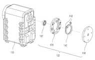
도 1은 본 발명에 따른 관절형 로봇의 소형 액추에이터에 장착되는 중력보상장치의 전체 구성도.
도 2는 본 발명에 따른 관절형 로봇의 소형 액추에이터에 장착되는 중력보상장치의 일분 분해 사시도.
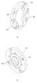
도 3은 본 발명에 따른 관절형 로봇의 소형 액추에이터에 장착되는 중력보상장치의 일측 사시도.
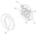
도 4는 본 발명에 따른 관절형 로봇의 소형 액추에이터에 장착되는 중력보상장치의 회전체와 고정체를 방향에 따라 도시한 도면.
도 5는 본 발명에 따른 관절형 로봇의 소형 액추에이터에 장착되는 중력보상장치의 분해 사시도.
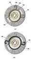
도 6은 본 발명에 따른 관절형 로봇의 소형 액추에이터에 장착되는 중력보상장치의 회전체 일부 분해도.
도 7은 본 발명에 따른 관절형 로봇의 소형 액추에이터에 장착되는 중력보상장치의 작동 예시도.1 is an overall configuration diagram of a gravity compensation device mounted to a small actuator of the articulated robot according to the present invention.
Figure 2 is an exploded perspective view of the gravity compensation device mounted on the small actuator of the articulated robot according to the present invention.
Figure 3 is a perspective view of one side of the gravity compensation device mounted to a small actuator of the articulated robot according to the present invention.
Figure 4 is a view showing the rotational body and the stationary body of the gravity compensation device mounted on the small actuator of the articulated robot according to the present invention in a direction.
Figure 5 is an exploded perspective view of the gravity compensation device mounted on the small actuator of the articulated robot according to the present invention.
Figure 6 is an exploded view of a part of the rotating body of the gravity compensation device mounted on the small actuator of the articulated robot according to the present invention.
7 is an operation example of a gravity compensation device mounted to a small actuator of the articulated robot according to the present invention.
상기한 목적을 달성하기 위한 본 발명은,The present invention for achieving the above object,
다수의 액추에이터들 및 이들을 상호 연결하는 연결 부재들을 포함하도록 구성된 다관절 로봇의 구조체에 연결되어 상기 구조체에 대하여 각 관절들이 회전 가능하게 지지하면서 동력을 발생시키는 구동모터에 직결된 감속기로 구성된 관절구동기와 회전각을 검출하는 센서, PID 제어기 및 모터 드라이브를 내부에 포함하여 구성된 소형 액추에이터 모듈과;An articulator configured as a reducer connected directly to a structure of an articulated robot configured to include a plurality of actuators and connecting members interconnecting the same, and directly connected to a drive motor that generates power while rotatably supporting each joint with respect to the structure; A small actuator module including a sensor for detecting a rotation angle, a PID controller, and a motor drive therein;
상기 액추에이터 모듈의 일측에 대접하여 밀착하는 결합을 이루며, 내부의 관절구동기에 연결되어 소정의 범위로 원형회전 가능하도록 하는 볼 베어링을 중심으로 통과하는 원판으로서, 회전되는 회전체와;A disk which forms a coupling to be in close contact with one side of the actuator module and is connected to an internal joint driver and passes around a ball bearing to enable circular rotation within a predetermined range, the rotating body being rotated;
상기 회전체에 대접하여 밀착하는 원판으로서, 볼 베어링을 내장하면서 일측으로 고정하며, 회전체가 원형회전 가능하도록 지지하는 고정체와;A disc for close contact with the rotating body, the fixed body supporting the rotating body so as to rotate in a circular direction while having a ball bearing therein;
상기 회전체와 고정체의 내측으로 각각 소정의 홈으로 형성된 원형슬롯을 구비하고, 상기 원형슬롯에 안착으로 일정한 원형을 유지하면서 한 번 이상 권선되어 양 끝단에 대칭으로 걸림부를 형성하여 원형슬롯에서 각각 회전체와 고정체에 구성된 고정부에 고정되어 회전가능하도록 장착된 토션 스프링과;A circular slot formed into a predetermined groove in each of the rotating body and the fixed body, each of which is wound one or more times while maintaining a constant circular shape by seating on the circular slot and symmetrically engaging parts at both ends thereof, respectively, in the circular slot. A torsion spring fixed to the fixed part constituted by the rotating body and the fixed body to be rotatable;
상기 토션 스프링의 양측 걸림부가 각각 다르게 회전체와 고정체의 고정부에 지지되어 회전체의 시계방향과 반시계 방향으로 탄성력을 발생시키는 탄성수단으로 상기 회전체의 회전각에 따라 중력 토크에 의한 중력부하가 발생되면, 상기 탄성수단에서 발생되는 원형회전방향의 탄성력에 의하여 보상되는 중력보상장치; 를 특징으로 하는 관절형 로봇의 소형 액추에이터에 장착되는 중력보상장치를 제공함으로써 달성하였다.Gravity due to gravity torque according to the rotational angle of the rotating body by the elastic means for supporting the two sides of the torsion spring, respectively, differently supported by the fixed parts of the rotating body and the fixed body to generate elastic force in the clockwise and counterclockwise direction of the rotating body. A load compensation device, the gravity compensation device being compensated by the elastic force in the circular rotation direction generated by the elastic means; It was achieved by providing a gravity compensation device mounted to a small actuator of the articulated robot.
이하, 본 발명의 바람직한 실시 예를 첨부한 도면에 의하여 상세하게 설명한다.Hereinafter, preferred embodiments of the present invention will be described in detail with reference to the accompanying drawings.
이에 앞서, 본 명세서 및 청구범위에 사용된 용어나 단어는 통상적이거나 사전적인 의미로 한정해서 해석되어서는 아니 되며, 발명자는 그 자신의 발명을 가장 최선의 방법으로 설명하기 위해 용어의 개념을 적절하게 정의할 수 있다는 원칙에 입각하여 본 발명의 기술적 사상에 부합하는 의미와 개념으로 해석되어야만 한다.Prior to this, terms and words used in the present specification and claims should not be construed as limited to ordinary or dictionary terms, and the inventor should appropriately interpret the concepts of the terms appropriately It should be interpreted in accordance with the meaning and concept consistent with the technical idea of the present invention based on the principle that it can be defined.
따라서, 본 명세서에 기재된 실시 예와 도면에 도시된 구성은 본 발명의 가장 바람직한 하나의 실시 예에 불과할 뿐이고, 본 발명의 기술적 사상을 모두 대변하는 것은 아니므로, 본 출원시점에 있어서 이들을 대체할 수 있는 다양한 균등물과 변형 예들이 있을 수 있음을 이해하여야 한다.Therefore, the embodiments described in the specification and the drawings shown in the drawings are only one of the most preferred embodiments of the present invention, and do not represent all of the technical idea of the present invention, they can be replaced at the time of the present application It should be understood that there may be various equivalents and variations.
도 1은 본 발명에 따른 관절형 로봇의 소형 액추에이터에 장착되는 중력보상장치의 전체 구성도이고, 도 2는 본 발명에 따른 관절형 로봇의 소형 액추에이터에 장착되는 중력보상장치의 일분 분해 사시도이다.1 is an overall configuration diagram of a gravity compensation device mounted to the small actuator of the articulated robot according to the present invention, Figure 2 is a partial exploded perspective view of the gravity compensation device mounted to the small actuator of the articulated robot according to the present invention.
도시된 바와 같이, 본 발명에 따른 관절형 로봇의 소형 액추에이터에 장착되는 중력보상장치는 다수의 액추에이터들로 구성된 다관절 로봇의 소형 액추에이터 모듈(110)에 포함된 모터의 크기 변경이나, 감속기어 변경 등을 사용하지 않고 중력보상을 실행되도록 소형 액추에이터 모듈(110)에 탈부착되는 탄성수단을 갖도록 조립된 회전체(120)와 고정체(130)에 포함된 토션 스프링(140) 구조체는 소형 경량화시키며, 중력 토크에 의하여 발생되는 회전각에 따라 자연 보상시키고, 에너지 효율을 증가시키며, 토션 스프링(140)의 특성을 이용하여 기어 망실을 방지하고, 필요한 방향으로의 중력 토크를 보상하는 것이다.As shown, the gravity compensation device mounted on the small actuator of the articulated robot according to the present invention is to change the size of the motor included in the
아울러, 인간의 동작과 닮은 운동을 행하는 기계장치인 소형 로봇은 복수의 관절을 갖도록 구성하며, 관절이 쉽게 움직일 수 있도록 소형 액추에이터 모듈(110)를 구성한다.In addition, the small robot, which is a mechanical device that performs a motion similar to a human motion, is configured to have a plurality of joints, and configures a
상기 소형 로봇의 구동모터 회전축에 중력의 영향으로 증가한 중력 토크를 줄이거나 상쇄시키기 위해서 토션 스프링(140)의 압축력이나 인장력을 이용하여 중력을 보상할 수 있는 중력보상장치(150)를 구성하여, 이를 구동모터의 회전축에 직결하거나 회전축에 부착된 감속기의 축에 직결하여 사용하는 장치이다.In order to reduce or offset the gravity torque increased by the influence of gravity on the drive motor rotation axis of the small robot by configuring a
일실시예로 로봇의 팔 관절에 구성되는 소형 액추에이터 모듈(110)은 다수의 액추에이터들 및 이들을 상호 연결하는 연결 부재들을 포함하도록 구성된다.In one embodiment, the
상기 소형 액추에이터 모듈은(110) 로봇의 다관절 구조체에 연결되어 상기 구조체에 대하여 각 관절들이 회전 가능하게 지지한다.The
상기 소형 액추에이터 모듈(110)를 구동을 위해 동력을 발생시키는 구동모터에 직결된 감속기로 구성된 관절구동기와 회전각을 검출하는 센서, PID 제어기 및 모터 드라이브를 내부에 포함하여 구성된다.The
이때, 본 발명은 로봇 팔과 같은 관절의 소형 액추에이터 모듈(110)에 중력보상장치(150)가 장착되어 중력의 보상 토크를 구동모터에 출력하여 상기 로봇 팔이 현재 위치를 유지하도록하는 것이다.At this time, according to the present invention, the
아울러, 상기 중력보상장치(150)는 도 3 내지 도 6에 도시한 바와 같이 원판 구조를 가지는 회전체(120) 및 고정체(130)의 내부에 결합을 이루는 토션 스프링(140)으로 구성된다.In addition, the
먼저 회전체(120)는 소형 액추에이터 모듈(110)의 일측에 직접 대접하여 밀착하는 결합을 이룬다.First, the rotating
상기 회전체(120)는 소형 액추에이터 모듈(110) 내부의 관절구동기에 연결되어 소정의 범위로 원형회전 가능하도록 하는 볼 베어링(102)을 중심으로 통과하는 원판이다.The rotating
즉, 상기 회전체(120)는 소형 액추에이터 모듈(110)의 구동모터와 직접 연결되어 회전되는 회전체(120)이다.That is, the rotating
그리고, 상기 회전체(120)에 대접하여 밀착하는 원판으로서 구성된 고정체(130)가 구성된다.And the fixed
상기 고정체(130)는 볼 베어링(102)을 내장하면서 일측으로 고정한다.The
상기 고정체(130)는 회전체(120)의 일측에 고정되면서 회전체(120)가 원형회전 가능하도록 지지한다.The
이렇게, 상호 결합한 상기 회전체(120)와 고정체(130)의 내측으로 탄성력 가지는 토션 스프링(140)이 결합을 이룬다.In this way, the
상기 회전체(120)와 고정체(130) 내부에 각각 소정의 홈으로 형성된 원형슬롯(104)을 구비하고, 상기 원형슬롯(104)에 토션 스프링(140)이 탄성 유지되도록 안착된다.The
상기 원형슬롯(104)은 회전체(120)와 고정체(130)의 내부에는 원형방향으로 운동을 안내해주는 원형슬롯(104)의 가이드로 토션 스프링(140)을 안착할 수 있는 공간을 확보하며, 회전운동을 가이드 한다.The circular slot 104 is a guide of the circular slot 104 to guide the movement in the circular direction inside the
상기 토션 스프링(140)은 일정한 원형을 유지하면서 한 번 이상 권선되어 양 끝단에 대칭으로 걸림부(142)를 형성한 것이다.The
아울러, 상기 토션 스프링(140)은 회전체(120)와 고정부(130)에 구성된 원형슬롯(104)에 각각 소정으로 돌출을 이루는 고정부(106)가 구비되며, 상기 토션 스프링(140)의 걸림부(142)가 각각 다른 위치에 고정된다.In addition, the
상기 토션 스프링(140)은 각각 회전체(120)와 고정체(130)에 구성된 고정부(106)에 고정되어 회전체(120)의 회전에 따라 회전가능하도록 장착된 것이다.The
상기 토션 스프링(140)은 회전체(120)와 고정체(130) 내부에 결합되며 회전에 따른 탄성수단으로 구성된다.The
이와 같은 중력보상장치(150)로 구성되는 토션 스프링(140)의 양측 걸림부(142)가 각각 다르게 회전체(120)와 고정체(130)의 고정부(106)에 지지 고정되어 회전체의 시계방향과 반시계 방향으로 탄성력을 발생시키는 탄성수단으로 상기 회전체(120)의 회전각에 따라 중력 토크에 의한 중력부하가 발생된다.Both sides of the engaging
상기 탄성수단에서 발생되는 회전체(120) 원형회전방향의 탄성력에 의하여 중력 보상이 이루어진다.Gravity compensation is performed by the elastic force in the circular rotation direction of the
즉, 상기 중력보상장치(150)는 원형슬롯(104)에 안착되어 회전체(120)와 고정체(130)의 고정부(106)에 토션 스프링(140)의 걸림부(142)가 각각 다르게 고정되어 양방향 회전에 대한 중력 토크를 보상하는 것이다.That is, the
도 7에 도시한 바와 같이 (a)를 고정체(130)와 회전체(120)의 위치는 중력 부하를 받지 않는 기본 형태로 하고, (b)에서 반시계 방향으로 90도 회전하면 부하와 하중을 받는 위치라 가정했을 때, (a)에서 토션 스프링(140)은 기본 형태를 유지하므로 토션 스프링(140)의 탄성력에 의한 보상이 일어나지 않지마, (b)와 같이 회전하는 과정에서 시계방향으로 토션 스프링(140)의 복원력이 발생하여 중력과 하중에 대한 보상을 할 수 있다.As shown in FIG. 7, the position of the
상기 토션 스프링(140)의 방향을 바꾸면 시계방향으로 회전시에 반시계 방향으로의 토션 스프링(140) 복원력이 발생하며, 하중의 크기에 따라 토션 스프링(140)의 종류, 형태, 고정체(130)와 회전체(120)에 체결되는 각도 등을 설정하여 적용할 수 있다.When the direction of the
정리하면, 소형 액추에이터 모듈(110)의 구동모터에 중력보상장치(150)의 볼 베어링(102)이 축으로 결합을 이루고, 구동모터의 회전에 따라 회전체(120)는 같이 회전하며, 회전체(120)에 결합된 로봇 팔이 회전함에 따라 중력의 영향을 받을 때, 상기 회전체(120)와 고정체(130) 내부에 구성된 토션 스프링(140)으로 구성된 탄성수단으로 회전방향에 따라 압축한다.In summary, the
상기 로봇 팔 등이 회전할 때, 중력으로 인하여 회전각이 커짐에 따라 부하가 커지는 반대 방향으로 토크의 보상이 일어나 부하를 줄임에 따라 토크는 구동모터에 가해지는 중력으로 인한 중력 토크의 양을 보상해주게 된다.As the robot arm rotates, the torque compensates in the opposite direction as the load increases as the rotation angle increases due to gravity, and as the load decreases, the torque compensates the amount of gravity torque due to gravity applied to the driving motor. You will.
아울러, 중력보상장치(150)는 회전체(120)의 시계방향으로 회전시 반시계 방향으로의 토션 스프링(140) 복원력 발생하는 것으로 회전각이 커짐에 따라 부하가 커지는 방향의 반대 방향으로 중력 토크를 보상하게 된다.In addition, the
한편, 상기 중력보상장치(150)는 탄성수단을 갖도록 조립된 회전체(120)와 고정체(130)에 포함된 토션 스프링(140)으로 다관절 로봇의 구조체에 구성되는 소형 액추에이터 모듈(110)에서 탈부착 가능하도록 구성된다.On the other hand, the
아울러, 상기 중력보상장치(150)는 실시예로 소형 액추에이터 모듈(110)에 장착되어 로봇 팔이 중력에 의해 낙하하지 않도록 현재 위치를 유지하기 위한 토크이다.In addition, the
상기 중력보상장치(150)는 실시예에 의한 로봇 팔의 관절을 구동하는 구동모터 구동에 의해 동작을 수행하는 중에 상기 관절에 작용하는 중력의 보상 토크가 이루어진다.The
이와 같이, 상기 중력보상장치(150)에 의해 회전각에 비례하여 증가되는 탄성력에 의하여 상기 중력 토크를 보상할 수 있으므로 구동모터의 출력 낭비를 줄이고, 구동모터에 가중되는 부하량을 축소시킬 수 있으므로, 소형 경량의 장치를 구성할 수 있게 된다.As such, the gravity torque can be compensated for by the elastic force increased in proportion to the rotation angle by the
아울러, 로봇의 소형 액추에이터 모듈(110)로 이루어진 관절의 구동으로 회전체(120)의 회전각에 따라 증가하는 중력으로 인한 토크를 보상하기 위한 중력보상장치(150)로 이용될 수 있으며, 특히 다축 관절을 가진 이족보행로봇 등에 이용될 수 있다.In addition, the drive of the joint consisting of a
이상과 같이, 본 발명은 비록 한정된 실시 예와 도면에 의해 설명되었으나, 본 발명은 이것에 의해 한정되지 않으며, 본 발명이 속하는 기술분야에서 통상의 지식을 가진 자에 의해 본 발명의 기술 사상과 아래에 기재될 청구범위의 균등 범위 내에서 다양한 수정 및 변형이 가능함은 물론이다.
While the present invention has been particularly shown and described with reference to exemplary embodiments thereof, it is to be understood that the invention is not limited to the disclosed exemplary embodiments. Various modifications and variations are possible within the scope of the appended claims.
102:볼 베어링104:원형슬롯
106:고정부110:소형 액추에이터 모듈
120:회전체130:고정체
140:토션 스프링142:걸림부
150:중력보상장치102: ball bearing 104: round slot
106: fixed part 110: small actuator module
120: rotating body 130: fixed body
140: torsion spring 142: hook
150: gravity compensation device
Claims (6)
Translated fromKorean상기 액추에이터 모듈의 일측에 대접하여 밀착하는 결합을 이루며, 내부의 관절구동기에 연결되어 소정의 범위로 원형회전 가능하도록 하는 볼 베어링을 중심으로 통과하는 원판으로서, 회전되는 회전체와;
상기 회전체에 대접하여 밀착하는 원판으로서, 볼 베어링을 내장하면서 일측으로 고정하며, 회전체가 원형회전 가능하도록 지지하는 고정체와;
상기 회전체와 고정체의 내측으로 각각 소정의 홈으로 형성된 원형슬롯을 구비하고, 상기 원형슬롯에 안착으로 일정한 원형을 유지하면서 한 번 이상 권선되어 양 끝단에 대칭으로 걸림부를 형성하여 원형슬롯에서 각각 회전체와 고정체에 구성된 고정부에 고정되어 회전가능하도록 장착된 토션 스프링과;
상기 토션 스프링의 양측 걸림부가 각각 다르게 회전체와 고정체의 고정부에 지지되어 회전체의 시계방향과 반시계 방향으로 탄성력을 발생시키는 탄성수단으로 상기 회전체의 회전각에 따라 중력 토크에 의한 중력부하가 발생되면, 상기 탄성수단에서 발생되는 원형회전방향의 탄성력에 의하여 보상되는 중력보상장치; 를 특징으로 하는 관절형 로봇의 소형 액추에이터에 장착되는 중력보상장치.
An articulator configured as a reducer connected directly to a structure of an articulated robot configured to include a plurality of actuators and connecting members interconnecting the same, and directly connected to a drive motor that generates power while rotatably supporting each joint with respect to the structure; A small actuator module including a sensor for detecting a rotation angle, a PID controller, and a motor drive therein;
A disk which forms a coupling to be in close contact with one side of the actuator module and is connected to an internal joint driver and passes around a ball bearing to enable circular rotation within a predetermined range, the rotating body being rotated;
A disc for close contact with the rotating body, the fixed body supporting the rotating body so as to rotate in a circular direction while having a ball bearing therein;
A circular slot formed into a predetermined groove in each of the rotating body and the fixed body, each of which is wound one or more times while maintaining a constant circular shape by seating on the circular slot and symmetrically engaging parts at both ends thereof, respectively, in the circular slot. A torsion spring fixed to the fixed part constituted by the rotating body and the fixed body to be rotatable;
Gravity due to gravity torque according to the rotational angle of the rotating body by the elastic means for supporting the two sides of the torsion spring, respectively, differently supported by the fixed parts of the rotating body and the fixed body to generate elastic force in the clockwise and counterclockwise direction of the rotating body. A load compensation device, the gravity compensation device being compensated by the elastic force in the circular rotation direction generated by the elastic means; Gravity compensation device mounted to the small actuator of the articulated robot.
상기 회전체와 고정체의 내부에는 원형방향으로 운동을 안내해주는 원형슬롯의 가이드가 설치되는 것을 특징으로 하는 관절형 로봇의 소형 액추에이터에 장착되는 중력보상장치.
The method of claim 1,
A gravity compensation device mounted to the small actuator of the articulated robot, characterized in that the guide of the circular slot for guiding the movement in the circular direction inside the rotating body and the fixed body.
상기 중력보상장치는,
원형슬롯을 구비하는 회전체와 고정체의 고정부에 토션 스프링의 걸림부가 각각 다르게 고정되어 양방향 회전에 대한 중력 토크를 보상하는 것을 특징으로 하는 관절형 로봇의 소형 액추에이터에 장착되는 중력보상장치.
The method of claim 1,
The gravity compensation device,
Gravity compensator mounted to the small actuator of the articulated robot, characterized in that the engaging portion of the torsion spring is fixed differently to the fixed part of the rotating body and the fixed body having a circular slot to compensate for the gravity torque for bidirectional rotation.
상기 중력보상장치는,
시계방향으로 회전시 반시계 방향으로의 토션 스프링 복원력 발생하는 것으로 회전각이 커짐에 따라 부하가 커지는 방향의 반대 방향으로 중력 토크를 보상하는 것을 특징으로 하는 관절형 로봇의 소형 액추에이터에 장착되는 중력보상장치.
The method of claim 3,
The gravity compensation device,
Gravity compensation mounted on the small actuator of the articulated robot, which generates the torsion spring restoring force in the counterclockwise direction when rotating in the clockwise direction and compensates the gravity torque in the direction opposite to the direction in which the load increases as the rotation angle increases. Device.
상기 중력보상장치는,
소형 액추에이터에 장착되어 로봇 관절이 중력에 의해 낙하하지 않도록 현재 위치를 유지하기 위한 토크인 것을 특징으로 하는 관절형 로봇의 소형 액추에이터에 장착되는 중력보상장치.
The method of claim 3,
The gravity compensation device,
A gravity compensation device mounted to the small actuator of the articulated robot, characterized in that the torque is for mounting on the small actuator to maintain the current position so that the robot joint does not fall by gravity.
상기 중력보상장치는,
탄성수단을 갖도록 조립된 회전체와 고정체에 포함된 토션 스프링으로 다관절 로봇의 구조체에 구성되는 소형 액추에이터 모듈에서 탈부착 가능한 것을 특징으로 하는 관절형 로봇의 소형 액추에이터에 장착되는 중력보상장치.The method of claim 1,
The gravity compensation device,
A gravity compensation device mounted to the small actuator of the articulated robot, characterized in that the detachable from the small actuator module configured in the structure of the articulated robot by a torsion spring included in the rotating body and the fixed body assembled to have an elastic means.
Priority Applications (1)
| Application Number | Priority Date | Filing Date | Title |
|---|---|---|---|
| KR1020110039161AKR101265763B1 (en) | 2011-04-26 | 2011-04-26 | Gravity compensation device installation to small size actuator of joint style robot |
Applications Claiming Priority (1)
| Application Number | Priority Date | Filing Date | Title |
|---|---|---|---|
| KR1020110039161AKR101265763B1 (en) | 2011-04-26 | 2011-04-26 | Gravity compensation device installation to small size actuator of joint style robot |
Publications (2)
| Publication Number | Publication Date |
|---|---|
| KR20120121278Atrue KR20120121278A (en) | 2012-11-05 |
| KR101265763B1 KR101265763B1 (en) | 2013-05-16 |
Family
ID=47507756
Family Applications (1)
| Application Number | Title | Priority Date | Filing Date |
|---|---|---|---|
| KR1020110039161AActiveKR101265763B1 (en) | 2011-04-26 | 2011-04-26 | Gravity compensation device installation to small size actuator of joint style robot |
Country Status (1)
| Country | Link |
|---|---|
| KR (1) | KR101265763B1 (en) |
Cited By (4)
| Publication number | Priority date | Publication date | Assignee | Title |
|---|---|---|---|---|
| KR20150030900A (en)* | 2013-09-13 | 2015-03-23 | (주)미래컴퍼니 | Structure and design method of control arm |
| CN104526716A (en)* | 2014-12-17 | 2015-04-22 | 上海交通大学 | Energy storage and energy saving type gravity balancing device for industrial robot |
| US10471610B2 (en) | 2015-06-16 | 2019-11-12 | Samsung Electronics Co., Ltd. | Robot arm having weight compensation mechanism |
| KR20210113504A (en) | 2020-03-06 | 2021-09-16 | 현대자동차주식회사 | Wearable apparatus for assisting muscular strength equipped with gravity compensation divce |
- 2011
- 2011-04-26KRKR1020110039161Apatent/KR101265763B1/enactiveActive
Cited By (6)
| Publication number | Priority date | Publication date | Assignee | Title |
|---|---|---|---|---|
| KR20150030900A (en)* | 2013-09-13 | 2015-03-23 | (주)미래컴퍼니 | Structure and design method of control arm |
| CN104526716A (en)* | 2014-12-17 | 2015-04-22 | 上海交通大学 | Energy storage and energy saving type gravity balancing device for industrial robot |
| CN104526716B (en)* | 2014-12-17 | 2016-07-06 | 上海交通大学 | A kind of industrial robot energy-storage economical type gravity balance device |
| US10471610B2 (en) | 2015-06-16 | 2019-11-12 | Samsung Electronics Co., Ltd. | Robot arm having weight compensation mechanism |
| KR20210113504A (en) | 2020-03-06 | 2021-09-16 | 현대자동차주식회사 | Wearable apparatus for assisting muscular strength equipped with gravity compensation divce |
| US12127990B2 (en) | 2020-03-06 | 2024-10-29 | Hyundai Motor Company | Gravity compensator applied to wearable muscular strength assisting apparatus |
Also Published As
| Publication number | Publication date |
|---|---|
| KR101265763B1 (en) | 2013-05-16 |
Similar Documents
| Publication | Publication Date | Title |
|---|---|---|
| CN102069495B (en) | Parallel robot | |
| KR100806966B1 (en) | Joint device of robot | |
| ES2659412T3 (en) | System and actuator method | |
| US8434384B2 (en) | Weight compensation mechanism and method using bevel gear and robot arm using the same | |
| JP5344155B2 (en) | Camber angle variable mechanism | |
| KR101270031B1 (en) | Weight compensation mechanism and robot arm using the same | |
| JP6545894B2 (en) | Flapping device | |
| KR101265763B1 (en) | Gravity compensation device installation to small size actuator of joint style robot | |
| JP2022523966A (en) | Integrated joint module for robots and walking robots to which it is applied | |
| US11897122B2 (en) | Robot hand | |
| KR20150047076A (en) | Torque-free linkage unit | |
| JP6458162B2 (en) | Flapping equipment | |
| KR101265284B1 (en) | On small size actuator interior of joint style robot included all style gravity compensation device | |
| JP2011255493A (en) | Actuator module usable for various forms of joints | |
| CN106457948A (en) | Rotary damper | |
| JP2016060022A (en) | Robot upper body support structure | |
| KR100801799B1 (en) | Gravity Compensator of Motor | |
| KR20190041714A (en) | Apparatus of robot joint | |
| JP6581235B1 (en) | Link mechanism | |
| KR20110133309A (en) | Joint Structure of Articulated Robot with Torque Compensating Load Balancer | |
| KR101332694B1 (en) | a haptic device with weight compensation function | |
| KR101207853B1 (en) | Actuator module applicable in various joint type and joint structure using the same | |
| JP2013249865A (en) | Actuator | |
| TW201215796A (en) | Parallel robot | |
| JP2007526967A (en) | Motion transmission device having a parallel motion transmission structure providing three degrees of freedom of translation |
Legal Events
| Date | Code | Title | Description |
|---|---|---|---|
| A201 | Request for examination | ||
| PA0109 | Patent application | Patent event code:PA01091R01D Comment text:Patent Application Patent event date:20110426 | |
| PA0201 | Request for examination | ||
| E902 | Notification of reason for refusal | ||
| PE0902 | Notice of grounds for rejection | Comment text:Notification of reason for refusal Patent event date:20121010 Patent event code:PE09021S01D | |
| PG1501 | Laying open of application | ||
| E701 | Decision to grant or registration of patent right | ||
| PE0701 | Decision of registration | Patent event code:PE07011S01D Comment text:Decision to Grant Registration Patent event date:20130412 | |
| GRNT | Written decision to grant | ||
| PR0701 | Registration of establishment | Comment text:Registration of Establishment Patent event date:20130510 Patent event code:PR07011E01D | |
| PR1002 | Payment of registration fee | Payment date:20130513 End annual number:3 Start annual number:1 | |
| PG1601 | Publication of registration | ||
| FPAY | Annual fee payment | Payment date:20160510 Year of fee payment:4 | |
| PR1001 | Payment of annual fee | Payment date:20160510 Start annual number:4 End annual number:4 | |
| FPAY | Annual fee payment | Payment date:20170510 Year of fee payment:5 | |
| PR1001 | Payment of annual fee | Payment date:20170510 Start annual number:5 End annual number:5 | |
| FPAY | Annual fee payment | Payment date:20180509 Year of fee payment:6 | |
| PR1001 | Payment of annual fee | Payment date:20180509 Start annual number:6 End annual number:6 | |
| FPAY | Annual fee payment | Payment date:20190508 Year of fee payment:7 | |
| PR1001 | Payment of annual fee | Payment date:20190508 Start annual number:7 End annual number:7 | |
| PR1001 | Payment of annual fee | Payment date:20210504 Start annual number:9 End annual number:9 | |
| PR1001 | Payment of annual fee | Payment date:20220510 Start annual number:10 End annual number:10 | |
| PR1001 | Payment of annual fee | Payment date:20230509 Start annual number:11 End annual number:11 | |
| PR1001 | Payment of annual fee | Payment date:20240417 Start annual number:12 End annual number:12 | |
| PR1001 | Payment of annual fee | Payment date:20250325 Start annual number:13 End annual number:13 |