KR20120120618A - Apparatus and method for controlling air volume - Google Patents
Apparatus and method for controlling air volumeDownload PDFInfo
- Publication number
- KR20120120618A KR20120120618AKR1020110038314AKR20110038314AKR20120120618AKR 20120120618 AKR20120120618 AKR 20120120618AKR 1020110038314 AKR1020110038314 AKR 1020110038314AKR 20110038314 AKR20110038314 AKR 20110038314AKR 20120120618 AKR20120120618 AKR 20120120618A
- Authority
- KR
- South Korea
- Prior art keywords
- motor
- rotational speed
- input
- air volume
- signal
- Prior art date
- Legal status (The legal status is an assumption and is not a legal conclusion. Google has not performed a legal analysis and makes no representation as to the accuracy of the status listed.)
- Withdrawn
Links
- 238000000034methodMethods0.000titleclaimsabstractdescription21
- 230000003247decreasing effectEffects0.000claimsdescription3
- 238000006243chemical reactionMethods0.000description5
- 230000007274generation of a signal involved in cell-cell signalingEffects0.000description5
- 238000010586diagramMethods0.000description4
- 230000007423decreaseEffects0.000description2
- 238000007664blowingMethods0.000description1
- 238000007599dischargingMethods0.000description1
- 230000007257malfunctionEffects0.000description1
Images


Classifications
- B—PERFORMING OPERATIONS; TRANSPORTING
- B01—PHYSICAL OR CHEMICAL PROCESSES OR APPARATUS IN GENERAL
- B01D—SEPARATION
- B01D46/00—Filters or filtering processes specially modified for separating dispersed particles from gases or vapours
- B01D46/42—Auxiliary equipment or operation thereof
- B01D46/44—Auxiliary equipment or operation thereof controlling filtration
- H—ELECTRICITY
- H02—GENERATION; CONVERSION OR DISTRIBUTION OF ELECTRIC POWER
- H02P—CONTROL OR REGULATION OF ELECTRIC MOTORS, ELECTRIC GENERATORS OR DYNAMO-ELECTRIC CONVERTERS; CONTROLLING TRANSFORMERS, REACTORS OR CHOKE COILS
- H02P6/00—Arrangements for controlling synchronous motors or other dynamo-electric motors using electronic commutation dependent on the rotor position; Electronic commutators therefor
- H02P6/08—Arrangements for controlling the speed or torque of a single motor
- B—PERFORMING OPERATIONS; TRANSPORTING
- B01—PHYSICAL OR CHEMICAL PROCESSES OR APPARATUS IN GENERAL
- B01D—SEPARATION
- B01D2273/00—Operation of filters specially adapted for separating dispersed particles from gases or vapours
- B01D2273/30—Means for generating a circulation of a fluid in a filtration system, e.g. using a pump or a fan
Landscapes
- Chemical & Material Sciences (AREA)
- Chemical Kinetics & Catalysis (AREA)
- Engineering & Computer Science (AREA)
- Power Engineering (AREA)
- Control Of Electric Motors In General (AREA)
- Air Conditioning Control Device (AREA)
Abstract
Translated fromKoreanDescription
Translated fromKorean본 발명은 풍량을 조절하기 위하여 모터의 회전속도를 제어하는 풍량조절 장치 및 풍량 조절방법에 관한 것이다.The present invention relates to a flow rate adjusting device and a flow rate adjusting method for controlling the rotational speed of the motor to adjust the air volume.
공기 청정기 등에 구비된 송풍장치는 상기 공기 청정기 등이 흡입하였던 실내공기를 토출구를 통하여 본체 외부로 토출하는 역할을 수행한다. 상기 공기 청정기 등의 본체 내부에 흡입되었던 실내공기를 본체 외부로 토출시키는 송풍력을 제공하기 위하여 모터가 사용되며, 상기 모터의 회전속도에 따라 토출되는 풍량이 조절된다.The blower provided in the air purifier or the like serves to discharge the indoor air sucked by the air cleaner or the like to the outside of the main body through the discharge port. A motor is used to provide a blowing force for discharging the indoor air sucked into the main body of the air cleaner, etc. to the outside of the main body, and the amount of air discharged is adjusted according to the rotational speed of the motor.
상기 토출되는 풍량과 관련하여, 종래의 풍량조절장치는 모터의 회전속도가 이미 정해져 있는 1단, 2단 등의 버튼을 선택하여 토출되는 풍량을 선택하도록 하였다. 이 경우, 모터에 대한 제어를 간단하게 구현할 수 있지만, 사용자가 원하는 풍량에 대한 세밀한 제어를 제공하지 못하였다. 즉, 사용자는 이미 결정된 풍량이외의 다른 풍량을 선택할 수 없어 다양한 풍량을 요구하는 사용자의 욕구를 충족할 수 없는 문제점이 있었다.In relation to the discharged air volume, the conventional airflow control device selects the airflow volume to be discharged by selecting buttons such as the first stage, the second stage, and the like, in which the rotational speed of the motor is already determined. In this case, the control of the motor can be easily implemented, but it does not provide detailed control of the air volume desired by the user. That is, the user can not select the other air volume other than the predetermined air volume has a problem that can not meet the user's desire for a variety of air volume.
본 발명의 풍량조절 장치 및 풍량조절 방법은 사용자가 풍량을 자유롭게 제어할 수 있도록 하는 풍량조절 장치 및 풍량조절 방법을 제공하는 것을 목적으로 한다.An object of the present invention is to provide a flow rate control device and a flow rate control method for allowing a user to freely control the flow rate.
상기 과제를 해결하기 위한 본 발명의 일실시예에 의한 풍량조절장치는, 출력 풍량에 대한 정보를 기계적 입력으로 수신하는 입력부; 상기 수신된 기계적 입력을 전기적인 입력신호로 변환하는 신호 변환부; 상기 입력신호를 이용하여 모터의 회전속도를 결정하고, 상기 결정된 모터의 회전속도에 따라 상기 모터를 제어하는 제어신호를 생성하는 컨트롤러; 및 상기 제어신호에 따라 회전속도가 제어되는 상기 모터를 포함할 수 있다.Airflow control device according to an embodiment of the present invention for solving the above problems, the input unit for receiving the information on the output airflow as a mechanical input; A signal converter converting the received mechanical input into an electrical input signal; A controller for determining a rotational speed of the motor using the input signal and generating a control signal for controlling the motor according to the determined rotational speed of the motor; And the motor whose rotation speed is controlled according to the control signal.
여기서 상기 입력부는, 회전다이얼을 포함하며 상기 회전다이얼의 회전 정도를 이용하여 상기 출력 풍량에 대한 정보를 수신할 수 있다.The input unit may include a rotation dial and receive information on the output air volume using a degree of rotation of the rotation dial.
여기서 상기 신호 변환부는, 상기 수신된 기계적 입력에 의하여 저항의 크기가 변화되는 가변저항을 포함하고, 상기 가변저항의 양단 전압을 상기 입력신호로 할 수 있다.Here, the signal converter may include a variable resistor whose resistance is changed by the received mechanical input, and the voltage between both ends of the variable resistor may be used as the input signal.
여기서 상기 컨트롤러는, 상기 입력신호에 대응하는 모터의 회전 속도가 설정되어 있는 테이블을 이용하여 상기 모터의 회전속도를 결정할 수 있다.Here, the controller may determine the rotation speed of the motor by using a table in which the rotation speed of the motor corresponding to the input signal is set.
여기서 상기 풍량조절장치는, 입력신호 변환부 및 상기 컨트롤러 사이에 배치되는 노이즈제거부를 더 포함할 수 있다.Here, the air volume control device may further include a noise removing unit disposed between the input signal converter and the controller.
여기서 상기 컨트롤러는, 상기 결정된 모터의 회전 속도와 현재 모터의 회전 속도를 비교하여, 상기 결정된 모터의 회전 속도가 더 빠르면 상기 모터의 회전 속도를 증가시키고, 상기 결정된 모터의 회전 속도가 더 느리면 상기 모터의 회전 속도를 감소시킬 수 있다.
Here, the controller compares the determined rotational speed of the motor with the rotational speed of the current motor, and if the determined rotational speed of the motor is faster, increases the rotational speed of the motor, and if the determined rotational speed of the motor is slower, the motor. It can reduce the rotation speed of.
상기 과제를 해결하기 위한 본 발명의 다른 실시예에 의한 풍량조절장치는, 출력 풍량에 대한 정보를 기계적 입력으로 수신하는 입력부; 상기 수신된 기계적 입력을 이용하여 모터의 회전속도를 제어하는 제어신호를 생성하는 제어신호 생성부; 상기 제어신호에 따라 회전속도가 제어되는 모터; 및 상기 모터와 접지부 사이에 구비되어 상기 모터의 구동여부를 제어하는 스위치부를 포함할 수 있다.Airflow control device according to another embodiment of the present invention for solving the above problems, the input unit for receiving the information on the output airflow as a mechanical input; A control signal generator for generating a control signal for controlling the rotational speed of the motor by using the received mechanical input; A motor whose rotation speed is controlled according to the control signal; And a switch unit provided between the motor and the ground unit to control driving of the motor.
여기서 상기 입력부는, 회전다이얼을 포함하며, 상기 회전다이얼의 회전 정도를 이용하여 상기 출력 풍량에 대한 정보를 수신할 수 있다.The input unit may include a rotation dial, and may receive information about the output air volume using the degree of rotation of the rotation dial.
여기서 상기 제어신호 생성부는, 상기 입력부의 기계적 입력에 의하여 저항의 크기가 변화되는 가변저항을 포함하고, 상기 가변저항의 저항의 크기에 따라 변화하는 상기 모터의 양단 전압을 상기 제어신호로 할 수 있다.The control signal generator may include a variable resistor whose resistance is changed by a mechanical input of the input unit, and the voltage of both ends of the motor that varies according to the resistance of the variable resistor may be used as the control signal. .
여기서 상기 스위치부는, 트랜지스터를 포함하며, 상기 트랜지스터의 소스는 상기 모터와 연결되고, 드레인은 상기 접지부와 연결되어, 게이트부에 인가되는 전압에 의하여 상기 모터의 구동여부가 제어될 수 있다.The switch unit may include a transistor, a source of the transistor is connected to the motor, a drain is connected to the ground part, and driving of the motor may be controlled by a voltage applied to the gate part.
본 발명의 풍량조절 장치 및 풍량조절 방법은 가변저항을 이용하여 사용자가 원하는 풍량을 입력받을 수 있으므로, 사용자의 의사에 따라 사용자가 원하는 정도의 풍량을 제공하여 사용자의 만족도를 높일 수 있는 효과를 가진다.Since the air volume adjusting device and the air volume adjusting method of the present invention can receive a desired air volume by using a variable resistor, the user can increase the user's satisfaction by providing a desired air volume according to the user's intention. .
도1은 본 발명의 일 실시예에 의한 풍량조절장치를 도시한 회로도이다.
도2는 본 발명의 일 실시예에 의한 풍량조절방법을 나타낸 순서도이다.
도3은 본 발명의 다른 실시예에 의한 풍량조절장치를 도시한 회로도이다.
도4는 본 발명의 다른 실시예에 의한 풍량조절방법을 나타낸 순서도이다.1 is a circuit diagram showing the airflow control apparatus according to an embodiment of the present invention.
Figure 2 is a flow chart showing the airflow control method according to an embodiment of the present invention.
3 is a circuit diagram showing the airflow control apparatus according to another embodiment of the present invention.
Figure 4 is a flow chart showing the airflow control method according to another embodiment of the present invention.
이하, 첨부된 도면을 참조하여 본 발명이 속하는 기술분야에서 통상의 지식을 가진 자가 본 발명을 용이하게 실시할 수 있도록 바람직한 실시예를 상세히 설명한다. 다만, 본 발명의 바람직한 실시예를 상세하게 설명함에 있어, 관련된 공지 기능 또는 구성에 대한 구체적인 설명이 본 발명의 요지를 불필요하게 흐릴 수 있다고 판단되는 경우에는 그 상세한 설명을 생략한다. 또한, 유사한 기능 및 작용을 하는 부분에 대해서는 도면 전체에 걸쳐 동일한 부호를 사용한다.Hereinafter, exemplary embodiments of the present invention will be described in detail with reference to the accompanying drawings so that those skilled in the art may easily implement the present invention. In the following detailed description of the preferred embodiments of the present invention, a detailed description of known functions and configurations incorporated herein will be omitted when it may make the subject matter of the present invention rather unclear. In the drawings, like reference numerals are used throughout the drawings.
덧붙여, 명세서 전체에서, 어떤 부분이 다른 부분과 '연결'되어 있다고 할 때, 이는 '직접적으로 연결'되어 있는 경우뿐만 아니라, 그 중간에 다른 소자를 사이에 두고 '간접적으로 연결'되어 있는 경우도 포함한다. 또한, 어떤 구성요소를 '포함'한다는 것은, 특별히 반대되는 기재가 없는 한 다른 구성요소를 제외하는 것이 아니라 다른 구성요소를 더 포함할 수 있다는 것을 의미한다.
In addition, in the entire specification, when a part is referred to as being 'connected' to another part, it may be referred to as 'indirectly connected' not only with 'directly connected' . Also, to "include" an element means that it may include other elements, rather than excluding other elements, unless specifically stated otherwise.
도1은 본 발명의 일 실시예에 따른 풍량조절장치를 도시한 회로도이다.1 is a circuit diagram showing the airflow control apparatus according to an embodiment of the present invention.
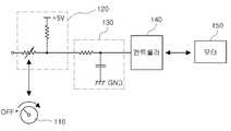
도1을 참조하면, 본 발명의 일 실시예에 따른 풍량조절장치는 입력부(110), 신호 변환부(120), 컨트롤러(140) 및 모터(150)을 포함할 수 있으며, 추가적으로, 상기 신호 변환부(120) 및 상기 컨트롤러(140) 사이에 노이즈제거부(130)를 더 포함할 수 있다.Referring to Figure 1, the airflow control apparatus according to an embodiment of the present invention may include an
이하 도1을 참조하여, 본 발명의 일 실시예에 따른 풍량조절장치를 설명한다.
Hereinafter, with reference to Figure 1, it will be described the air volume control device according to an embodiment of the present invention.
입력부(110)는, 출력 풍량에 대한 정보를 기계적 입력으로 수신할 수 있다. 상기 입력부(110)는 회전다이얼을 포함하여 구성될 수 있으며, 상기 회전 다이얼의 회전 정도를 이용하여 상기 출력 풍량에 대한 정보를 상기 풍량조절장치에 입력할 수 있다.The
상기 다이얼의 회전 가능 범위와 출력되는 풍량의 범위를 대응시켜 상기 다이얼의 회전 정도에 따라 출력 풍량이 선택될 수 있다. 예를 들어, 상기 풍량조절장치에 의하여 제공할 수 있는 최대 풍량을 100, 최소 풍량을 0으로 두었을 때, 상기 다이얼이 오른쪽으로 최대한 회전 할 수 있는 위치에서 100의 풍량을 제공하고, 상기 다이얼을 왼쪽으로 최대한 회전 할 수 있는 위치에서 0의 풍량을 제공하며, 다이얼이 나머지 위치에 있는 경우에는 상기 최대 다이얼의 위치에 대한 현재 다이얼의 위치의 비율에 의하여 풍량이 결정될 수 있다.The output air volume may be selected according to the degree of rotation of the dial by matching the rotatable range of the dial with the range of the output air volume. For example, when the maximum air volume that can be provided by the air volume control device is 100 and the minimum air volume is 0, the air volume of 100 is provided at a position where the dial can rotate to the right as far as possible, and the dial The air volume of 0 is provided at a position that can be rotated to the left as far as possible, and when the dial is at the remaining position, the air volume may be determined by a ratio of the position of the current dial to the position of the maximum dial.
상기 회전다이얼은 출력 풍량에 대한 정보를 상기 다이얼의 회전이라는 기계적 입력으로 구현한 실시예로서, 상기 회전다이얼이외에 기 설정된 범위 내에서 상하, 또는 좌우로 이동가능한 레버를 이용하여 상기 출력 풍량에 대한 정보를 상기 풍량조절장치에 기계적으로 입력할 수 있다.The rotary dial is an embodiment in which the information on the output air volume is implemented as a mechanical input called rotation of the dial, and the information on the output air volume using a lever that is movable up, down, left and right within a preset range other than the rotary dial. Can be mechanically input to the airflow control device.
상기 입력되는 출력 풍량에 대한 정보는 결국 상기 풍량조절장치가 출력해야 하는 풍량, 즉 목표풍량으로 볼 수 있다.
The information on the input output air volume can be viewed as the air volume that is to be output by the air volume control device, that is, the target air volume.
신호 변환부(120)는, 수신된 기계적 입력을 전기적인 입력신호로 변환할 수 있다. 상기 신호 변환부(120)는 상기 수신된 기계적 입력에 의하여 저항의 크기가 변화되는 가변저항을 포함하며, 상기 가변저항의 양단 전압을 상기 입력신호로 할 수 있다.The
구체적으로, 상기 신호 변환부(120)는 직렬로 연결된 고정저항 및 가변저항으로 구성될 수 있다. 상기 직렬 연결된 고정저항 및 가변저항의 양단에 일정한 전압을 인가하고, 상기 가변저항의 크기를 상기 회전다이얼의 회전 등 기계적 입력에 의하여 변화시키면, 상기 가변저항 양단의 전압 또한 상기 가변저항의 크기에 따라 변화된다.In detail, the
즉, 사용자가 상기 입력부(130)에서 회전다이얼의 회전 등 기계적 입력을 통하여 입력한 목표풍량이 상기 가변저항 양단의 전압으로 변환된 것이므로 상기 가변저항 양단의 전압을 상기 풍향조절장치의 입력신호로 할 수 있다.
That is, since the target air volume inputted by the user through the mechanical input such as rotation of the rotary dial by the
컨트롤러(140)는, 입력신호를 이용하여 모터(150)의 회전속도를 결정하고, 상기 결정된 모터(150)의 회전속도에 따라 상기 모터(150)를 제어하는 제어신호를 생성할 수 있다. 상기 컨트롤러(140)는 상기 입력신호에 대응하는 모터(150)의 회전속도가 설정되어 있는 테이블을 이용하여 상기 모터(150)의 회전속도를 결정할 수 있다.The
또한, 상기 컨트롤러(140)는 상기 결정된 모터(150)의 회전속도와 현재 모터(150)의 회전속도를 비교하여, 상기 결정된 모터(150)의 회전속도가 더 빠르면 상기 모터(150)의 회전 속도를 증가시키고, 상기 결정된 모터(150)의 회전속도가 더 느리면 상기 모터(150)의 회전 속도를 감소시키는 방법으로, 상기 모터(150)의 회전속도를 제어할 수 있다.In addition, the
상기 목표풍량에 대한 정보가 담겨있는 전기적 입력신호만으로는 얼마나 모터(150)를 회전하여야 상기 목표 풍량을 얻을 수 있는 지 알 수 없다. 따라서, 상기 컨트롤러(140)의 구성을 통하여 상기 목표풍량을 얻기 위한 모터(150)의 회전속도를 결정할 수 있다.It is not possible to know how to achieve the target air volume by rotating the
구체적으로, 상기 컨트롤러(140)는 상기 목표풍량을 얻기 위한 모터(150)의 회전속도를 결정하기 위하여, 상기 입력신호에 대응하는 모터(150)의 회전속도가 설정되어 있는 테이블을 이용할 수 있다. 상기 입력신호 즉, 가변저항의 양단 전압을 상기 신호 변환부(120)로부터 입력받으면, 테이블에서 상기 입력된 가변저항의 양단 전압과 대응되는 상기 모터(150)의 회전속도를 찾아서, 상기 모터(150)의 회전속도를 모터(150)의 목표회전속도로 결정할 수 있다.Specifically, the
상기 테이블을 이용하여 모터(150)의 회전속도를 결정하더라도, 상기 결정된 모터(150)의 회전속도를 얻기 위하여는 모터(150)의 동작을 제어하기 위한 제어신호가 필요하다. 따라서, 상기 컨트롤러(140)의 구성을 통하여 상기 모터(150)의 동작을 제어하기 위한 제어신호를 생성할 수 있다.Even if the rotation speed of the
구체적으로, 상기 결정된 모터(150)의 회전속도와 현재 모터(150)의 회전속도를 비교하여, 상기 결정된 모터(150)의 회전속도가 더 빠르면 상기 모터(150)의 회전 속도를 증가시키기 위한 제어신호를 발생시키고, 상기 결정된 모터(150)의 회전속도가 더 느리면 상기 모터(150)의 회전 속도를 감소시키는 제어신호를 발생시킬 수 있다.Specifically, by comparing the determined rotational speed of the
상기 모터(150)가 직류 모터인 경우, 상기 모터(150) 속도의 제어는 모터(150) 양단의 전압의 크기를 제어함으로써 구현할 수 있다. 모터(150) 양단의 전압의 크기가 커지면 모터(150)의 속도는 빨라지고, 모터(150) 양단의 전압의 크기가 작아지면 모터(150)의 속도는 느려진다. 따라서, 상기 컨트롤러(140)는 증폭기의 구성을 더 포함하여, 상기 입력신호를 일정한 비율로 증폭시켜 이를 제어신호로서 상기 모터(150)의 양단에 전압으로 공급할 수 있다.When the
또한, 상기 모터(150)가 교류 모터인 경우, 상기 컨트롤러(140)는 상기 입력신호에 따라 상기 모터(150)에 제공하는 교류 전압의 주파수를 변경시키는 제어신호를 생성할 수 있다. 교류 모터의 경우 입력되는 전압의 주파수에 따라서 모터의 회전속도가 변화되므로, 상기 교류 전압의 주파수를 변경시키는 제어신호를 이용하여 상기 모터(150)의 속도를 제어할 수 있다.
In addition, when the
모터(150)는 상기 제어신호에 따라 회전속도가 제어될 수 있다. 상기 모터(150)는 공기청정기 등 송풍장치가 토출하는 풍량을 모터(150)의 회전속도를 이용하여 조절할 수 있다. 상기 모터(150)는 상기 공기청정기 등 송풍장치 내부의 공기를 외부로 토출하기 위하여 상기 모터(150)의 회전축에 팬(fan)을 구비할 수 있다.
The rotation speed of the
추가적으로, 상기 풍량조절장치는 상기 신호 변환부(120) 및 상기 컨트롤러(140) 사이에 노이즈제거부(130)를 더 포함할 수 있다.In addition, the air volume adjusting device may further include a
상기 노이즈제거부(130)는 상기 신호 변환부(120)에서 상기 컨트롤러(140)로 입력되는 입력신호에 대하여 존재할 수 있는 노이즈를 제거할 수 있으며, 상기 노이즈 제거를 위하여 상기 노이즈제거부(130)는 저역통과필터(LPF:Low Pass Filter)일 수 있다.The
상기 컨트롤러(140)는 상기 신호 변환부(120)로부터 수신한 입력신호를 증폭하여 모터(150)의 구동을 위한 모터(150) 양단 전압으로 제공할 수 있다. 이 경우에 있어서, 상기 입력신호에 존재하는 노이즈에 의하여 모터(150)의 양단에 지나치게 큰 전압이 인가될 수 있다. 상기 모터(150) 양단에 지나치게 큰 전압이 인가되면, 상기 모터(150)가 손상되거나 오작동을 일으켜 사고가 발생할 위험이 있다. 따라서, 이와 같은 위험을 미연에 방지하기 위하여, 상기 컨트롤러(140)에 입력되는 입력신호에 대하여 저역통과필터를 통과하도록하여 노이즈를 제거하도록 할 수 있다.
The
도2는 본 발명의 일 실시예에 따른 풍량조절방법을 나타낸 순서도이다.Figure 2 is a flow chart showing the airflow control method according to an embodiment of the present invention.
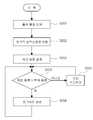
도2를 참조하면, 본 발명의 일 실시예에 따른 풍량조절방법은 출력 풍량 입력 단계(S201), 전기적 입력신호 변환 단계(S202), 목표 풍량 설정 단계(S203), 목표풍량과 현재풍량 비교단계(S204) 및 모터속도 제어단계(S205, S206)를 포함할 수 있다.Referring to Figure 2, the airflow control method according to an embodiment of the present invention, the output airflow input step (S201), the electrical input signal conversion step (S202), the target airflow setting step (S203), the target airflow and the current airflow comparison step (S204) and the motor speed control step (S205, S206).
이하, 도2를 참조하여, 본 발명의 일 실시예에 따른 풍량조절방법을 설명한다.
Hereinafter, with reference to Figure 2, it will be described the air flow control method according to an embodiment of the present invention.
출력 풍량 입력 단계(S201)는 출력 풍량에 대한 정보를 기계적 입력으로 수신할 수 있다. 상기 기계적 입력은 회전다이얼의 회전일 수 있으며, 상기 회전다이얼의 회전정도를 이용하여 상기 출력 풍량에 대한 정보를 입력받을 수 있다.
The output air volume input step S201 may receive information on the output air volume as a mechanical input. The mechanical input may be a rotation of a rotary dial, and may receive information about the output air volume using the degree of rotation of the rotary dial.
전기적 입력신호 변환 단계(S202)는 수신된 기계적 입력을 전기적인 입력신호로 변환할 수 있다. 구체적으로 직렬로 연결된 고정저항 및 가변저항에 일정한 전압이 인가되는 경우에 있어서, 상기 회전다이얼의 회전 등 기계적 입력에 의하여 상기 가변저항의 크기를 변화시키면, 상기 가변저항의 양단 전압 또한 상기 가변저항의 크기 변화에 따라 변화하게 된다.The electrical input signal conversion step S202 may convert the received mechanical input into an electrical input signal. Specifically, in the case where a constant voltage is applied to the fixed resistor and the variable resistor connected in series, when the magnitude of the variable resistor is changed by a mechanical input such as the rotation of the rotary dial, the voltage across both ends of the variable resistor is also changed. It changes as the size changes.
즉, 사용자가 상기 회전다이얼의 회전 등 기계적 입력을 통하여 입력한 출력 풍량에 대한 정보가 상기 가변저항 양단의 전압으로 변환할 수 있다.
That is, the information on the amount of output air inputted by the user through a mechanical input such as rotation of the rotary dial may be converted into a voltage across the variable resistor.
목표 풍량 설정 단계(S203)는 상기 변환된 전기적 입력신호를 이용하여 모터의 회전속도를 결정할 수 있으며, 상기 결정된 모터의 회전속도에 의하여 목표 풍량을 설정할 수 있다.In the target air flow setting step (S203), the rotation speed of the motor may be determined using the converted electrical input signal, and the target air flow may be set based on the determined rotation speed of the motor.
구체적으로 상기 입력신호에 대응하는 모터의 회전속도가 설정되어 있는 테이블을 이용하여 상기 모터의 회전속도를 결정할 수 있으며, 상기 결정된 모터의 회전속도에 따라 출력되는 풍량이 결정된다. 따라서, 상기 모터의 회전속도를 결정함으로써 목표 풍량을 설정할 수 있다.
Specifically, the rotational speed of the motor may be determined using a table in which the rotational speed of the motor corresponding to the input signal is set, and the amount of air outputted is determined according to the determined rotational speed of the motor. Therefore, the target air volume can be set by determining the rotational speed of the motor.
목표풍량과 현재풍량 비교단계(S204)는 상기 결정된 모터의 회전속도에 의하여 토출되는 풍량과 현재의 모터의 회전속도에 의하여 토출되는 풍량을 비교할 수 있다. 상기 풍량의 비교는 실제 토출되는 풍량을 비교할 수 있지만, 모터의 회전속도를 통하여 비교할 수도 있다.
The target air volume and the current air volume comparing step (S204) may compare the air volume discharged by the determined rotation speed of the motor and the air volume discharged by the current rotation speed of the motor. The air volume comparison may compare the actual air volume, but may also be compared through the rotational speed of the motor.
모터속도 제어단계(S205, S206)는 상기 목표풍량과 현재풍량 비교단계(S204)에서 비교한 결과에 따라 모터속도를 제어할 수 있다.The motor speed control steps S205 and S206 may control the motor speed according to a result of comparing the target air volume with the current air volume comparison step S204.
구체적으로, 상기 목표풍량이 현재풍량보다 크면, 모터의 회전속도를 상승시켜 토출되는 풍량을 증가시키고, 상기 목표풍량이 현재풍량보다 작으면, 모터의 회전속도를 하강시켜 토출되는 풍량을 감소시킬 수 있다.
Specifically, when the target air volume is greater than the current air flow rate, the rotational speed of the motor is increased to increase the discharged air volume. If the target air flow rate is smaller than the current air flow rate, the air flow rate is decreased by decreasing the rotational speed of the motor. have.
도3은 본 발명의 일 실시예에 따른 풍량조절장치를 나타낸 회로도이다.3 is a circuit diagram showing the airflow control apparatus according to an embodiment of the present invention.
도3을 참조하면, 본 발명의 일 실시예에 따른 풍량조절장치는, 입력부(310), 제어신호 생성부(320), 모터(330) 및 스위치부(340)를 포함할 수 있다.Referring to FIG. 3, the airflow control apparatus according to an embodiment of the present invention may include an
이하 도3을 참조하여, 본 발명의 다른 실시예에 따른 풍량조절장치를 설명한다.
Hereinafter, with reference to Figure 3, it will be described the air flow rate adjusting apparatus according to another embodiment of the present invention.
입력부(310)은, 출력 풍량에 대한 정보를 기계적 입력으로 수신할 수 있다. 상기 입력부(310)는 회전다이얼을 포함하여 구성될 수 있으며, 상기 회전다이얼의 회전 정도를 이용하여 상기 출력 풍량에 대한 정보를 상기 풍량조절장치에 입력할 수 있다. 이하, 구체적인 내용은 앞서 설명한 입력부(110)와 동일하므로 생략한다.
The
제어신호 생성부(320)는 상기 수신된 기계적 입력을 이용하여 모터(330)의 회전속도를 제어하는 제어신호를 생성할 수 있다. 상기 제어신호 생성부(320)는 상기 입력부(310)의 기계적 입력에 의하여 저항의 크기가 변화되는 가변저항을 포함하고, 상기 가변저항의 저항의 크기에 따라 변화하는 상기 모터(330)의 양단 전압을 상기 제어신호로 할 수 있다.The
상기 가변저항과 모터(330)는 도3에 도시된바와 같이 직렬로 연결될 수 있으며, 이 경우 상기 모터(330)의 양단에 인가되는 전압은 전압분배의 원칙에 따라 결정된다. 즉, 상기 가변저항의 저항의 크기가 작을수록 상기 모터(330)의 양단에 걸리는 전압의 크기는 커지며, 상기 가변저항의 저항의 크기가 클수록 상기 모터(330)의 양단에 걸리는 전압의 크기는 작아진다. 따라서, 상기 가변저항의 저항의 크기가 변화함에 따라 상기 모터(330) 양단에 걸리는 전압의 크기가 달라질 수 있다.The variable resistor and the
상기 모터(330) 양단에 걸리는 전압의 크기에 따라 상기 모터(330)의 회전속도가 변화되므로, 상기 모터(330)의 회전속도를 상기 모터(330)의 회전속도를 제어하는 제어신호로 할 수 있다.
Since the rotation speed of the
모터(330)는 상기 제어신호에 따라 회전속도가 제어될 수 있다. 상기 모터(330)는 공기청정기 등 송풍장치가 토출하는 풍량을 상기 모터(330)의 회전속도를 이용하여 조절할 수 있다. 상기 모터(330)는 상기 공기청정기 등 송풍장치 내부의 공기를 외부로 토출하기 위하여 상기 모터(330)의 회전축에 팬(fan)을 구비할 수 있다.
The
스위치부(340)는 상기 모터(330)와 접지부 사이에 구비되어 상기 모터(330)의 구동여부를 제어할 수 있다. 또한, 상기 스위치부(340)는 트랜지스터로 구성될 수 있으며, 상기 트랜지스터의 소스부는 상기 모터(330)와 연결되고, 드레인부는 상기 접지부와 연결되어, 게이트부에 인가되는 전압에 의하여 상기 모터(330)의 구동여부를 제어할 수 있다.The
상기 스위치부(340)는 상기 모터(330)와 접지부 사이의 전기적 연결을 연결할 수도 있고, 끊을 수도 있다. 상기 모터(330)와 접지부 사이의 전기적 연결이 끊어지면 상기 모터(330)는 구동될 수 없으므로, 상기 스위치부의 동작에 의하여 상기 모터(330)의 구동여부가 결정될 수 있다.The
구체적으로 상기 스위치부(340)가 트랜지스터로 구성되면, 상기 트랜지스터의 소스부는 상기 모터(330)와 연결되고, 드레인부는 접지부와 연결될 수 있다. 이 경우, 게이트부에 기 설정된 전압 이상이 인가되는 경우에 한하여 상기 소스부와 드레인부 사이에 전류가 흐를 수 있으므로, 상기 게이트부에 기 설정된 전압 이상이 인가되는 지 여부에 따라 상기 모터(330)의 구동여부를 결정할 수 있다.
Specifically, when the
도4는 본 발명의 일 실시예에 따른 풍량조절방법을 나타낸 순서도이다.Figure 4 is a flow chart showing the airflow control method according to an embodiment of the present invention.
도4를 참조하면, 본 발명의 일 실시예에 따른 풍량조절방법은 모터구동단계(S401), 출력 풍량 입력 단계(S402), 제어신호 생성 단계(S403), 및 모터속도 제어단계(S404, S405, S406)을 포함할 수 있다.4, the airflow control method according to an embodiment of the present invention, the motor driving step (S401), the output airflow input step (S402), the control signal generation step (S403), and the motor speed control steps (S404, S405) , S406).
이하, 도4를 참조하여, 본 발명의 일 실시예에 따른 풍량조절방법을 설명한다.
Hereinafter, with reference to Figure 4, it will be described in the air flow control method according to an embodiment of the present invention.
모터구동단계(S401)는 모터의 구동을 위한 신호의 입력 여부에 따라 모터의 구동여부를 결정할 수 있다. 상기 모터의 구동을 위한 신호는 모터와 접지부 사이에 존재하는 스위치부에 대한 개폐를 결정하는 신호일 수 있으며, 구체적으로 상기 스위치부는 트랜지스터로 구현될 수 있다. 이 경우 상기 모터의 구동을 위한 신호는 게이트 전압일 수 있다. 따라서, 상기 모터구동단계(S401)에서는 상기 게이트에 기 설정값 이상의 전압이 인가되는지 여부를 판단하여, 기 설정값 이상인 경우에 한하여 모터를 구동할 수 있다.
The motor driving step S401 may determine whether to drive the motor according to whether a signal for driving the motor is input. The signal for driving the motor may be a signal for determining the opening and closing of the switch unit existing between the motor and the ground unit. Specifically, the switch unit may be implemented as a transistor. In this case, the signal for driving the motor may be a gate voltage. Therefore, in the motor driving step (S401), it is determined whether a voltage equal to or greater than a preset value is applied to the gate, and the motor may be driven only when the voltage is equal to or greater than a preset value.
출력 풍량 입력 단계(S402)는 출력 풍량에 대한 정보를 기계적 입력으로 수신할 수 있다. 상기 기계적 입력은 회전다이얼의 회전일 수 있으며, 상기 회전다이얼의 회전정도를 이용하여 상기 출력 풍량에 대한 정보를 입력받을 수 있다.
The output air volume input step S402 may receive information on the output air volume as a mechanical input. The mechanical input may be a rotation of a rotary dial, and may receive information about the output air volume using the degree of rotation of the rotary dial.
제어신호 생성단계(S403)는 수신된 기계적 입력을 이용하여 모터의 회전속도를 제어하는 제어신호를 생성할 수 있다. 구체적으로, 가변저항과 직렬로 연결된 모터에 있어서, 상기 기계적 입력에 의하여 가변저항의 크기가 변화됨으로써, 상기 모터의 양단에 인가되는 전압의 크기를 조절할 수 있다. 상기 모터의 양단전압에 의하여 모터의 회전속도가 결정되므로, 상기 모터의 양단전압을 상기 모터의 회전속도를 제어하는 제어신호로 볼 수 있다. 즉, 상기 제어신호 생성단계(S403)는 상기 기계적 입력에 의하여 변화되는 가변저항을 이용하여 모터의 회전속도를 제어하는 제어신호를 생성할 수 있다.
Control signal generation step (S403) may generate a control signal for controlling the rotational speed of the motor by using the received mechanical input. Specifically, in the motor connected in series with the variable resistor, the magnitude of the variable resistor is changed by the mechanical input, thereby controlling the magnitude of the voltage applied to both ends of the motor. Since the rotation speed of the motor is determined by the voltage at both ends of the motor, the voltage at both ends of the motor may be viewed as a control signal for controlling the rotation speed of the motor. That is, the control signal generation step (S403) may generate a control signal for controlling the rotational speed of the motor by using a variable resistor changed by the mechanical input.
모터속도 제어단계(S404, S405, S406)는 상기 제어신호에 따라 모터의 속도를 제어할 수 있다. 현재 모터의 양단 전압에 비하여 상기 제어신호에 의하여 인가된 모터의 양단 전압이 상승하였다면, 상기 모터속도를 상승시켜 토출하는 풍량을 증가시킬 수 있다. 반대로, 현재 모터의 양단 전압에 비하여 상기 제어신호에 의하여 인가된 모터의 양단 전압이 하강하였다면, 상기 모터속도를 하강시켜 토출하는 풍량을 감소시킬 수 있다.
Motor speed control steps (S404, S405, S406) may control the speed of the motor in accordance with the control signal. If the voltage across the motor applied by the control signal is increased compared to the voltage between the current and the both ends of the motor, the amount of air discharged by increasing the motor speed may be increased. On the contrary, if the voltage at both ends of the motor applied by the control signal is lower than the voltage at both ends of the current motor, the amount of air discharged by lowering the motor speed can be reduced.
본 발명은 상술한 실시형태 및 첨부된 도면에 의해 한정되지 아니한다. 첨부된 청구범위에 의해 권리범위를 한정하고자 하며, 청구범위에 기재된 본 발명의 기술적 사상을 벗어나지 않는 범위 내에서 다양한 형태의 치환, 변형 및 변경이 가능하다는 것은 당 기술분야의 통상의 지식을 가진 자에게 자명할 것이다.The present invention is not limited by the above-described embodiment and the accompanying drawings. It will be understood by those skilled in the art that various changes in form and details may be made therein without departing from the spirit and scope of the invention as defined by the appended claims, .
110: 입력부120: 신호 변환부
130: 노이즈제거부140: 컨트롤러
150: 모터
S201: 출력 풍량 입력 단계S202: 전기적 입력신호 변환 단계
S203: 목표 풍량 설정 단계S204: 목표풍량과 현재풍량 비교단계
S205, S206: 모터속도 제어단계
310: 입력부320: 제어신호생성부
330: 모터340: 스위치부
S401: 모터구동단계 S402: 출력 풍량 입력 단계
S403: 제어신호 생성 단계S404, S405, S406: 모터속도 제어단계110: input unit 120: signal conversion unit
130: noise removing unit 140: controller
150: motor
S201: output air volume input step S202: electrical input signal conversion step
S203: target air volume setting step S204: target air volume and current air volume comparing step
S205, S206: motor speed control step
310: input unit 320: control signal generation unit
330: motor 340: switch unit
S401: Motor driving step S402: Output air flow input step
S403: Control signal generation step S404, S405, S406: Motor speed control step
Claims (10)
Translated fromKorean상기 수신된 기계적 입력을 전기적인 입력신호로 변환하는 신호 변환부;
상기 입력신호를 이용하여 모터의 회전속도를 결정하고, 상기 결정된 모터의 회전속도에 따라 상기 모터를 제어하는 제어신호를 생성하는 컨트롤러; 및
상기 제어신호에 따라 회전속도가 제어되는 상기 모터를 포함하는 풍량조절장치.
An input unit to receive information on the output air volume as a mechanical input;
A signal converter converting the received mechanical input into an electrical input signal;
A controller for determining a rotational speed of the motor using the input signal and generating a control signal for controlling the motor according to the determined rotational speed of the motor; And
Air flow rate control device including the motor is controlled to the rotational speed in accordance with the control signal.
상기 입력부는 회전다이얼을 포함하며, 상기 회전다이얼의 회전 정도를 이용하여 상기 출력 풍량에 대한 정보를 수신하는 풍량조절장치.
The method of claim 1,
The input unit includes a rotation dial, the air volume control device for receiving information on the output air volume using the degree of rotation of the rotary dial.
상기 신호 변환부는 상기 수신된 기계적 입력에 의하여 저항의 크기가 변화되는 가변저항을 포함하고, 상기 가변저항의 양단 전압을 상기 입력신호로 하는 풍량조절장치.
The method of claim 1,
And the signal converter includes a variable resistor whose resistance is changed by the received mechanical input, and uses the voltage at both ends of the variable resistor as the input signal.
상기 입력신호에 대응하는 모터의 회전 속도가 설정되어 있는 테이블을 이용하여 상기 모터의 회전속도를 결정하는 풍량조절장치.
The method of claim 1, wherein the controller,
And a rotation speed of the motor is determined by using a table in which the rotation speed of the motor corresponding to the input signal is set.
상기 신호 변환부 및 상기 컨트롤러 사이에 배치되는 노이즈제거부를 더 포함하는 풍량조절장치.
The method of claim 1,
And a noise removing unit disposed between the signal converter and the controller.
상기 결정된 모터의 회전 속도와 현재 모터의 회전 속도를 비교하여, 상기 결정된 모터의 회전 속도가 더 빠르면 상기 모터의 회전 속도를 증가시키고, 상기 결정된 모터의 회전 속도가 더 느리면 상기 모터의 회전 속도를 감소시키는 풍량조절장치.
The method of claim 1, wherein the controller,
By comparing the determined rotational speed of the motor and the rotational speed of the current motor, if the determined rotational speed of the motor is faster, the rotational speed of the motor is increased, and if the determined rotational speed of the motor is slower, the rotational speed of the motor is decreased. Airflow control device to let.
상기 수신된 기계적 입력을 이용하여 모터의 회전속도를 제어하는 제어신호를 생성하는 제어신호 생성부;
상기 제어신호에 따라 회전속도가 제어되는 모터; 및
상기 모터와 접지부 사이에 구비되어 상기 모터의 구동여부를 제어하는 스위치부를 포함하는 풍량조절장치.
An input unit to receive information on the output air volume as a mechanical input;
A control signal generator for generating a control signal for controlling the rotational speed of the motor by using the received mechanical input;
A motor whose rotation speed is controlled according to the control signal; And
And a switch unit disposed between the motor and the ground unit to control driving of the motor.
상기 입력부는 회전다이얼을 포함하며, 상기 회전다이얼의 회전 정도를 이용하여 상기 출력 풍량에 대한 정보를 수신하는 풍량조절장치.
The method of claim 7, wherein
The input unit includes a rotation dial, the air volume control device for receiving information on the output air volume using the degree of rotation of the rotary dial.
상기 제어신호 생성부는 상기 입력부의 기계적 입력에 의하여 저항의 크기가 변화되는 가변저항을 포함하고, 상기 가변저항의 저항의 크기에 따라 변화하는 상기 모터의 양단 전압을 상기 제어신호로 하는 풍량조절장치.
The method of claim 7, wherein
The control signal generating unit includes a variable resistor in which the magnitude of the resistance is changed by a mechanical input of the input unit, and the airflow control device using the voltage at both ends of the motor that varies according to the magnitude of the resistance of the variable resistor as the control signal.
상기 스위치부는 트랜지스터를 포함하며, 상기 트랜지스터의 소스는 상기 모터와 연결되고, 드레인은 상기 접지부와 연결되어, 게이트부에 인가되는 전압에 의하여 상기 모터의 구동여부가 제어되는 풍량조절장치.The method of claim 7, wherein
The switch unit includes a transistor, the source of the transistor is connected to the motor, the drain is connected to the ground portion, the air flow control device is controlled whether the motor is driven by a voltage applied to the gate portion.
Priority Applications (1)
| Application Number | Priority Date | Filing Date | Title |
|---|---|---|---|
| KR1020110038314AKR20120120618A (en) | 2011-04-25 | 2011-04-25 | Apparatus and method for controlling air volume |
Applications Claiming Priority (1)
| Application Number | Priority Date | Filing Date | Title |
|---|---|---|---|
| KR1020110038314AKR20120120618A (en) | 2011-04-25 | 2011-04-25 | Apparatus and method for controlling air volume |
Publications (1)
| Publication Number | Publication Date |
|---|---|
| KR20120120618Atrue KR20120120618A (en) | 2012-11-02 |
Family
ID=47507259
Family Applications (1)
| Application Number | Title | Priority Date | Filing Date |
|---|---|---|---|
| KR1020110038314AWithdrawnKR20120120618A (en) | 2011-04-25 | 2011-04-25 | Apparatus and method for controlling air volume |
Country Status (1)
| Country | Link |
|---|---|
| KR (1) | KR20120120618A (en) |
- 2011
- 2011-04-25KRKR1020110038314Apatent/KR20120120618A/ennot_activeWithdrawn
Similar Documents
| Publication | Publication Date | Title |
|---|---|---|
| US8054018B2 (en) | Multi-level programming of motor for a ventilation system | |
| TWI400874B (en) | Bi-power motor controlling system and motor controlling apparatus thereof | |
| JP2014059116A (en) | Air cleaner | |
| US20120274252A1 (en) | Fan motor control device | |
| CN109706874B (en) | Multi-pneumatic system of road sweeping equipment and driving and controlling method thereof | |
| JP4876674B2 (en) | Rotational speed control device | |
| CN102741619B (en) | Ventilator | |
| JP6255576B2 (en) | Ventilation equipment | |
| TWI472147B (en) | Fan speed control circuit | |
| KR20120120618A (en) | Apparatus and method for controlling air volume | |
| JP6865361B1 (en) | Ventilation device | |
| KR101103018B1 (en) | Constant air flow control of the ventilation system | |
| JP6130152B2 (en) | Range food | |
| US20130015792A1 (en) | Motor driving circuit and motor device | |
| JP6285000B2 (en) | Range food | |
| JP6290362B2 (en) | Range food | |
| JP6221057B2 (en) | Ventilation equipment | |
| WO2004010061A3 (en) | Energy store circuit for controlling rotor rotation | |
| JP2017122575A (en) | Range hood | |
| CN207198538U (en) | A kind of adaptive cooling control circuit of projector's height above sea level | |
| JP5267284B2 (en) | Control device for fan filter unit | |
| JP2015047000A (en) | Ventilation device | |
| US20230243361A1 (en) | Blower and method for controlling blower | |
| US20090108790A1 (en) | Control structure of an electric fan | |
| JP2014166048A (en) | Power use comparison device and method |
Legal Events
| Date | Code | Title | Description |
|---|---|---|---|
| PA0109 | Patent application | Patent event code:PA01091R01D Comment text:Patent Application Patent event date:20110425 | |
| PG1501 | Laying open of application | ||
| PC1203 | Withdrawal of no request for examination | ||
| WITN | Application deemed withdrawn, e.g. because no request for examination was filed or no examination fee was paid |