KR20120118352A - Mobile terminal - Google Patents
Mobile terminalDownload PDFInfo
- Publication number
- KR20120118352A KR20120118352AKR1020110035860AKR20110035860AKR20120118352AKR 20120118352 AKR20120118352 AKR 20120118352AKR 1020110035860 AKR1020110035860 AKR 1020110035860AKR 20110035860 AKR20110035860 AKR 20110035860AKR 20120118352 AKR20120118352 AKR 20120118352A
- Authority
- KR
- South Korea
- Prior art keywords
- slide member
- mobile terminal
- case
- slide
- recess
- Prior art date
- Legal status (The legal status is an assumption and is not a legal conclusion. Google has not performed a legal analysis and makes no representation as to the accuracy of the status listed.)
- Granted
Links
Images


Classifications
- H—ELECTRICITY
- H04—ELECTRIC COMMUNICATION TECHNIQUE
- H04B—TRANSMISSION
- H04B1/00—Details of transmission systems, not covered by a single one of groups H04B3/00 - H04B13/00; Details of transmission systems not characterised by the medium used for transmission
- H04B1/38—Transceivers, i.e. devices in which transmitter and receiver form a structural unit and in which at least one part is used for functions of transmitting and receiving
- G—PHYSICS
- G06—COMPUTING OR CALCULATING; COUNTING
- G06F—ELECTRIC DIGITAL DATA PROCESSING
- G06F1/00—Details not covered by groups G06F3/00 - G06F13/00 and G06F21/00
- G06F1/16—Constructional details or arrangements
- G06F1/1613—Constructional details or arrangements for portable computers
- G06F1/1615—Constructional details or arrangements for portable computers with several enclosures having relative motions, each enclosure supporting at least one I/O or computing function
- G06F1/1624—Constructional details or arrangements for portable computers with several enclosures having relative motions, each enclosure supporting at least one I/O or computing function with sliding enclosures, e.g. sliding keyboard or display
- G—PHYSICS
- G06—COMPUTING OR CALCULATING; COUNTING
- G06F—ELECTRIC DIGITAL DATA PROCESSING
- G06F1/00—Details not covered by groups G06F3/00 - G06F13/00 and G06F21/00
- G06F1/16—Constructional details or arrangements
- G—PHYSICS
- G06—COMPUTING OR CALCULATING; COUNTING
- G06F—ELECTRIC DIGITAL DATA PROCESSING
- G06F1/00—Details not covered by groups G06F3/00 - G06F13/00 and G06F21/00
- G06F1/16—Constructional details or arrangements
- G06F1/1613—Constructional details or arrangements for portable computers
- G06F1/1633—Constructional details or arrangements of portable computers not specific to the type of enclosures covered by groups G06F1/1615 - G06F1/1626
- G06F1/1637—Details related to the display arrangement, including those related to the mounting of the display in the housing
- G06F1/1647—Details related to the display arrangement, including those related to the mounting of the display in the housing including at least an additional display
- G—PHYSICS
- G06—COMPUTING OR CALCULATING; COUNTING
- G06F—ELECTRIC DIGITAL DATA PROCESSING
- G06F1/00—Details not covered by groups G06F3/00 - G06F13/00 and G06F21/00
- G06F1/16—Constructional details or arrangements
- G06F1/1613—Constructional details or arrangements for portable computers
- G06F1/1633—Constructional details or arrangements of portable computers not specific to the type of enclosures covered by groups G06F1/1615 - G06F1/1626
- G06F1/1675—Miscellaneous details related to the relative movement between the different enclosures or enclosure parts
- G06F1/1683—Miscellaneous details related to the relative movement between the different enclosures or enclosure parts for the transmission of signal or power between the different housings, e.g. details of wired or wireless communication, passage of cabling
- H—ELECTRICITY
- H04—ELECTRIC COMMUNICATION TECHNIQUE
- H04M—TELEPHONIC COMMUNICATION
- H04M1/00—Substation equipment, e.g. for use by subscribers
- H04M1/02—Constructional features of telephone sets
- H—ELECTRICITY
- H04—ELECTRIC COMMUNICATION TECHNIQUE
- H04M—TELEPHONIC COMMUNICATION
- H04M1/00—Substation equipment, e.g. for use by subscribers
- H04M1/02—Constructional features of telephone sets
- H04M1/0202—Portable telephone sets, e.g. cordless phones, mobile phones or bar type handsets
- H04M1/0206—Portable telephones comprising a plurality of mechanically joined movable body parts, e.g. hinged housings
- H04M1/0208—Portable telephones comprising a plurality of mechanically joined movable body parts, e.g. hinged housings characterized by the relative motions of the body parts
- H04M1/0235—Slidable or telescopic telephones, i.e. with a relative translation movement of the body parts; Telephones using a combination of translation and other relative motions of the body parts
- H04M1/0237—Sliding mechanism with one degree of freedom
- H—ELECTRICITY
- H04—ELECTRIC COMMUNICATION TECHNIQUE
- H04M—TELEPHONIC COMMUNICATION
- H04M1/00—Substation equipment, e.g. for use by subscribers
- H04M1/02—Constructional features of telephone sets
- H04M1/23—Construction or mounting of dials or of equivalent devices; Means for facilitating the use thereof
- H04M1/236—Construction or mounting of dials or of equivalent devices; Means for facilitating the use thereof including keys on side or rear faces
- H—ELECTRICITY
- H04—ELECTRIC COMMUNICATION TECHNIQUE
- H04M—TELEPHONIC COMMUNICATION
- H04M1/00—Substation equipment, e.g. for use by subscribers
- H04M1/60—Substation equipment, e.g. for use by subscribers including speech amplifiers
- H04M1/6033—Substation equipment, e.g. for use by subscribers including speech amplifiers for providing handsfree use or a loudspeaker mode in telephone sets
- H04M1/6041—Portable telephones adapted for handsfree use
- H—ELECTRICITY
- H04—ELECTRIC COMMUNICATION TECHNIQUE
- H04M—TELEPHONIC COMMUNICATION
- H04M2250/00—Details of telephonic subscriber devices
- H04M2250/22—Details of telephonic subscriber devices including a touch pad, a touch sensor or a touch detector
- H—ELECTRICITY
- H04—ELECTRIC COMMUNICATION TECHNIQUE
- H04M—TELEPHONIC COMMUNICATION
- H04M2250/00—Details of telephonic subscriber devices
- H04M2250/52—Details of telephonic subscriber devices including functional features of a camera
Landscapes
- Engineering & Computer Science (AREA)
- Theoretical Computer Science (AREA)
- Computer Hardware Design (AREA)
- Physics & Mathematics (AREA)
- Human Computer Interaction (AREA)
- General Engineering & Computer Science (AREA)
- General Physics & Mathematics (AREA)
- Signal Processing (AREA)
- Computer Networks & Wireless Communication (AREA)
- Mathematical Physics (AREA)
- Telephone Set Structure (AREA)
- Devices For Indicating Variable Information By Combining Individual Elements (AREA)
Abstract
Translated fromKoreanDescription
Translated fromKorean본 발명은 어느 바디가 다른 바디에 대하여 슬라이딩 이동하는 이동 단말기에 관한 것이다.The present invention relates to a mobile terminal in which one body slides relative to another body.
단말기(terminal)는 기능이 다양화됨에 따라 예를 들어, 사진이나 동영상의 촬영, 음악이나 동영상 파일의 재생, 게임, 방송의 수신 등의 복합적인 기능들을 갖춘 멀티미디어 기기(Multimedia player) 형태로 구현되고 있다.As the functions are diversified, the terminal is implemented in the form of a multimedia device having a complex function of, for example, taking pictures or moving pictures, playing music or moving picture files, receiving games and receiving broadcasts have.
단말기는 이동 가능여부에 따라 휴대용 단말기(mobile/portable terminal) 및 고정 단말기(stationary terminal)으로 나뉠 수 있다. 휴대용 단말기는 휴대가 가능하면서 음성 및 영상 통화를 수행할 수 있는 기능, 정보를 입?출력할 수 있는 기능 및 데이터를 저장할 수 있는 기능 등을 하나 이상 갖춘 휴대용 기기이다.The terminal can move And may be divided into a mobile terminal and a stationary terminal depending on whether the mobile terminal is a mobile terminal or a mobile terminal. A portable terminal is a portable device that is portable and has one or more functions for making voice and video calls, inputting and outputting information, and storing data.
이러한 단말기의 기능 지지 및 증대를 위해, 단말기의 구조적인 부분 및/또는 소프트웨어적인 부분을 개량하는 것이 고려될 수 있다.In order to support and enhance the functionality of such terminals, it may be considered to improve the structural and / or software parts of the terminal.
본 발명의 일 목적은 보다 단순한 구조를 가지며, 제1바디와 제2바디를 서로 상대 이동시킬 수 있는 슬라이드 모듈을 구비한 이동 단말기를 제공하기 위한 것이다.An object of the present invention is to provide a mobile terminal having a simpler structure, and having a slide module that can move the first body and the second body relative to each other.
본 발명의 다른 목적은 단말기 바디를 보다 슬림화할 수 있는 이동 단말기를 제공하기 위한 것이다.
Another object of the present invention is to provide a mobile terminal that can make the terminal body more slim.
이와 같은 본 발명의 해결 과제를 달성하기 위하여, 본 발명의 일 실시예에 따르는 이동 단말기는, 제1바디와 제2바디, 상기 제1바디에 장착되는 제1 디스플레이부 및 상기 제1바디와 제2바디를 서로에 대하여 상대 이동시키도록 형성되는 슬라이드 모듈을 더 포함하고, 상기 슬라이드 모듈은, 상기 제1바디에 결합되는 제1 슬라이드 부재 및 측단에 서로 교차하는 방향으로 각각 연장되는 제1절곡부와 제2절곡부를 구비하여, 상기 제1 슬라이드 부재의 측면의 적어도 일부를 감싸도록 형성되는 제2 슬라이드 부재를 포함하고, 상기 제1절곡부와 제2절곡부는 상기 제1 디스플레이부의 측면으로부터 일정 간격 이격되어 배치된다.In order to achieve the above object of the present invention, the mobile terminal according to an embodiment of the present invention, the first body and the second body, the first display unit mounted on the first body and the first body and the first Further comprising a slide module for moving the two bodies relative to each other, the slide module, the first slide member coupled to the first body and the first bent portion extending in the direction crossing each other on the side ends, respectively And a second slide member, the second slide member being formed to surround at least a portion of the side surface of the first slide member, wherein the first bent portion and the second bent portion are spaced a predetermined distance from the side surface of the first display portion. Spaced apart.
본 발명과 관련한 일 예에 따르면, 상기 제1바디는, 상기 제1바디의 외관을 형성하는 제1케이스와 제2케이스 및 제1 디스플레이부가 안착될 수 있도록, 상기 제2케이스의 일면에서 리세스되는 리세스부를 더 포함할 수 있다.According to an example related to the present invention, the first body is recessed on one surface of the second case so that the first case, the second case, and the first display unit forming the appearance of the first body can be seated. The recess may further include a recess.
본 발명과 관련한 일 예에 따르면, 상기 제1 슬라이드 부재는, 상기 리세스부에 대응하는 형상의 관통홀을 구비하고, 상기 리세스부는 상기 제1 슬라이드 부재와 결합시, 상기 관통홀에 적어도 일부가 삽입된다.According to an example related to the present disclosure, the first slide member may include a through hole having a shape corresponding to the recessed portion, and when the recessed portion is coupled to the first slide member, at least a part of the recessed portion may be formed in the through hole. Is inserted.
본 발명과 관련한 일 예에 따르면, 상기 슬라이드 모듈은, 상기 제1 슬라이드 부재와 제2 슬라이드 부재를 탄성적으로 연결하는 탄성구동부를 더 포함할 수 있다.According to an example related to the present disclosure, the slide module may further include an elastic driving unit for elastically connecting the first slide member and the second slide member.
본 발명과 관련한 일 예에 따르면, 상기 제1바디는, 장착되는 디스플레이부와 상기 탄성구동부의 일단과의 거리를 좁히도록, 상기 슬라이딩 모듈의 일부와 일체화되어 형성된다.According to an example related to the present invention, the first body is integrally formed with a part of the sliding module so as to narrow the distance between the display unit to be mounted and one end of the elastic driving unit.
또한 상기한 과제를 실현하기 위하여 본 발명은, 닫힌 상태와 열린 상태를 구현할 수 있도록 서로 연결되는 제1바디와 제2바디 및 상기 제1바디와 제2바디를 슬라이드 연결하는 슬라이드 모듈을 포함하고, 상기 슬라이드 모듈은, 상기 제1바디에 고정되는 제1 슬라이드 부재 및 상기 제1 슬라이드 부재의 측면에, 상기 제1 슬라이드 부재가 삽입되어 슬라이드 이동할 수 있도록 형성되는 레일홈을 구비하는 제2 슬라이드 부재를 포함하고, 상기 제1바디에 장착되는 디스플레이부와 상기 레일홈은 서로 적층되지 않도록, 동일 평면 상에 서로 이격되어 배치되는 이동 단말기를 개시한다.In addition, in order to realize the above object, the present invention includes a slide module for slidingly connecting the first body and the second body and the first body and the second body connected to each other to implement a closed state and an open state, The slide module may include a second slide member having a first slide member fixed to the first body and a rail groove formed at a side surface of the first slide member so that the first slide member is inserted and slides. And a display unit mounted on the first body and the rail groove are spaced apart from each other on the same plane so as not to be stacked on each other.
상기와 같이 구성되는 본 발명의 적어도 하나의 실시예에 관련된 이동 단말기는 레일홈이 디스플레이부의 하면에 적층되지 않고, 동일 평면상에 서로 이격되어 배치되므로, 제2 절곡부의 두께만큼 제1 바디의 두께를 줄일 수 있다.In the mobile terminal according to the at least one embodiment of the present invention configured as described above, since the rail grooves are not stacked on the lower surface of the display unit and are spaced apart from each other on the same plane, the thickness of the first body is equal to the thickness of the second bent portion. Can be reduced.
또한, 디스플레이부의 측방향 유동 방지와 관련된 형상 또는 이를 방지하기 위하여 추가되는 부품이 필요 없게 되어, 단말기의 경량화 및 제조공정의 간소화를 이룰 수 있다.In addition, the shape associated with preventing the lateral flow of the display unit or an additional component for preventing the same may be eliminated, thereby reducing the weight of the terminal and simplifying the manufacturing process.
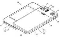
도 1은 본 발명의 일 실시예에 따르는 이동 단말기의 닫힌 상태를 나타내는 사시도.
도 2는 도 1의 이동 단말기의 열린 상태를 나타내는 사시도.
도 3은 도 2의 이동 단말기이 배면을 보인 사시도.
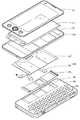
도 4는 도 1의 분해 사시도.
도 5는 본 발명의 일실시예와 관련된 상부바디의 배면도.
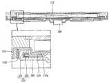
도 6a은 도 2의 라인(Ⅳ-Ⅳ)를 따라 절단한 상태에서의 제1바디의 단면도이고, 도 6b는 도 6a에서 제2케이스의 변형실시예를 도시한 도면.
도 7은 본 발명의 다른 일실시예에 따르는 도 1의 분해 사시도.
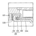
도 8은 본 발명의 다른 일실시예에 따르는 도 2의 라인(Ⅳ-Ⅳ)를 따라 절단한 상태에서의 제1바디의 단면도.1 is a perspective view showing a closed state of a mobile terminal according to an embodiment of the present invention.
2 is a perspective view illustrating an open state of the mobile terminal of FIG. 1.
3 is a perspective view showing the rear of the mobile terminal of FIG.
4 is an exploded perspective view of FIG. 1;
Figure 5 is a rear view of the upper body associated with an embodiment of the present invention.
FIG. 6A is a cross-sectional view of the first body in a state cut along the line IV-IV of FIG. 2, and FIG. 6B illustrates a modified embodiment of the second case in FIG. 6A.
Figure 7 is an exploded perspective view of Figure 1 according to another embodiment of the present invention.
8 is a cross-sectional view of the first body in a cut state along the line IV-IV of FIG. 2 in accordance with another embodiment of the present invention.
이하, 본 발명의 일실시예에 따르는 이동 단말기에 대하여 도면을 참조하여 보다 상세하게 설명한다. 본 명세서에서는 서로 다른 실시예라도 동일?유사한 구성에 대해서는 동일?유사한 참조번호를 부여하고, 그 설명은 처음 설명으로 갈음한다. 본 명세서에서 사용되는 단수의 표현은 문맥상 명백하게 다르게 뜻하지 않는 한, 복수의 표현을 포함한다.Hereinafter, a mobile terminal according to an embodiment of the present invention will be described in more detail with reference to the accompanying drawings. In the present specification, different embodiments are given the same or similar reference numerals for the same or similar configurations, and the description is replaced with the first description. As used herein, the singular forms "a", "an" and "the" include plural referents unless the context clearly dictates otherwise.
도 1과 도 2는 본 발명과 관련된 이동 단말기의 상면 사시도로서, 도 1은 이동 단말기가 닫힌 상태이고, 도 2는 이동 단말기가 열린 상태를 나타낸다.1 and 2 are top perspective views of a mobile terminal according to the present invention, FIG. 1 is a closed state of the mobile terminal, and FIG. 2 is a state in which the mobile terminal is opened.
도 1 및 도 2에서 보는 것과 같이, 이동 단말기(100)는 서로에 대해 이동 가능하게 결합되는 제1바디(110)와 제2바디(120)를 구비하고 있다. 도 1 및 도 2에 개시된 이동 단말기(100)는 특히, 폭방향(가로방향) 슬라이드 이동에 의하여 열림상태를 구현하는 예가 제시되고 있다. 다만, 본 발명은 길이방향(세로방향) 슬라이드 이동에 의하여 열림상태를 구현하는 예에도 적용될 수 있다.As shown in FIGS. 1 and 2, the
도 1에 예시된 바와 같이 제1바디(110)가 제2바디(120)와 중첩되게 배치된 상태를 닫힌 상태(closed configuration)라 칭할 수 있으며, 도 2에 예시된 바와 같이 제1바디(110)가 일 방향으로 이동되어 제2바디(120)의 적어도 일 부분이 노출한 상태를 열린 상태(open configuration,)라 칭할 수 있다. 본 실시예에서는 제1바디(110) 및 제2바디(120)의 베이스(130)에 대한 '이동'으로서 슬라이딩을 예시하고 있으나, 본 발명은 그에 제한되지 않는다. 예를 들어, 제1바디(110)와 제2바디(120) 중 어느 하나가 다른 하나에 대해 스윙(swing) 또는 스위블(swivel)되도록 구성될 수도 있다.As illustrated in FIG. 1, a state in which the
상기 이동 단말기(100)는 닫힌 상태에서 주로 대기 모드로 작동하지만 사용자의 조작에 의해 대기 모드가 해제되기도 한다. 그리고, 상기 이동 단말기(100)는 열린 상태에서 주로 통화 모드 등으로 작동하지만 사용자의 조작 또는 소정 시간의 경과에 의해 대기 모드로 전환되기도 한다.The
제1바디(110)와 제2바디(120)의 상면에 각각 배치될 수 있는 기능이나 부품은 이동 단말기(100)가 어떠한 기능을 강조하는가 또는 어떤 사용자 인터페이스(User Interface)를 추구하는가에 따라 다양한 예가 도출될 수 있다. 일 예로서, 도 2와 같이 상부 바디(110)의 상면에 디스플레이부(113)를 설치하고, 하부 바디(120)의 상면에 입력이나 제어명령을 위한 제2 조작부(123)를 설치할 수 있다.The functions or parts that can be disposed on the upper surfaces of the
상기 음향 출력부(114)는 리시버(Receiver) 또는 스피커(speaker)의 형태로 구현될 수 있다. 상기 제1 영상 입력부(115)는 사용자 등에 대한 이미지 또는 동영상을 촬영하기 위한 카메라 모듈과 같은 형태로 구현될 수 있다. 상기 제1 조작부(116)는 본 발명의 일 예에 관련된 이동 단말기의 동작을 제어하기 위한 명령을 입력받는다. 음향 입력부(117)는 마이크의 형태로 구현될 수 있다. 음향 입력부(117)는 디스플레이부(113)를 기준으로 음향 출력부(114)에 대칭되게 배치될 수 있다.The
제1바디(110)와 마찬가지로, 프론트 케이스(121)와 리어 케이스(122)가 제2바디(120)를 형성할 수 있다. 제2바디(120), 구체적으로 프론트 케이스(121)의 전면(front face)에는 제2 조작부(123, 도 2 참조)가 배치될 수 있다.Like the
제2바디(120)의 일 측에는 통화 등을 위한 안테나 외에 방송신호 수신용 안테나(132)가 배치될 수 있다. 상기 안테나(132)는 제2바디(120)에서 인출 가능하게 설치될 수 있다.
On one side of the
도 2를 참조하면, 제1바디(110)가 제2바디(120)에 대하여 슬라이딩되면, 이에 의해, 닫힌 상태(도 1의 상태)에서 제1바디(110)에 의해 오버랩되는 제2바디(120)의 전면에 배치된 제2 조작부(123)가 제1바디(110)에 대하여 노출된다.Referring to FIG. 2, when the
노출된 제2 조작부(123)의 키들은 디스플레이부(113)에서 출력되는 내용과 관련한 입력을 받도록 구성될 수 있다. 제2 조작부(123)가 언어키(한글 자음 및 모음/영어 알파벳 등) 및 숫자키를 포함할 수 있으며, 언어키는 쿼티(QWERTY) 배열을 이루도록 배치될 수 있다. 언어키가 쿼티 배열을 이루도록 배치됨에 따라, 사용자는 영문으로 문자, 메모, 이메일 등을 쉽게 작성할 수 있게 된다.The exposed keys of the
제2 조작부(123)가 터치 스크린이라면, 터치 스크린의 노출된 부분에는 키들로서 기능키의 아이콘이 터치 입력 가능한 상태로 출력될 수 있다. 예를 들어, 디스플레이부(113)에 동영상이 출력되는 경우라면, 기능키들은 일시정지, 재생, 뒤로, 앞으로, 재생 목록 등과 같은 기능의 구현을 위한 명령을 입력받도록 구성될 수 있다.If the
상기 설명에서는 제2바디(120)의 전면에 제2 조작부(123)가 배치되는 것을 기준으로 하였으나, 본 발명은 이에 한정되지 않는다. 예를 들어, 제2바디(120)의 전면에는 디스플레이부(113)와 연동되는 제2 디스플레이부가 배치될 수 있다.
In the above description, the
도 3은 도 2의 이동 단말기(100)이 배면을 보인 사시도이다.3 is a perspective view showing the rear side of the
본 도면을 참조하면, 제2바디(120)의 주면과 평행한(마주하는) 측면에는 제3 조작부(124), 인터페이스(126) 등이 배치될 수 있다.Referring to this drawing, a
상기 제1 내지 제3 조작부(116, 123, 124)는 사용자 입력부(user input portion)라 통칭될 수 있으며, 사용자가 촉각적인 느낌을 가면서 조작하게 되는 방식(tactile manner)이라면 어떤 방식이든 채용될 수 있다.The first to
예를 들어, 상기 사용자 입력부는 사용자의 푸시 또는 터치 조작에 의해 명령 또는 정보를 입력받을 수 있는 돔 스위치 또는 터치 스크린, 터치 패드로 구현되거나, 키를 회전시키는 휠 또는 조그 방식이나 조이스틱과 같이 조작하는 방식 등으로도 구현될 수 있다.For example, the user input unit may be implemented as a dome switch or a touch screen that can receive a command or information by a user's push or touch operation, a touch pad, or a wheel that rotates keys or a jog or a joystick. It may also be implemented in a manner and the like.
기능적인 면에서, 제1 조작부(116)는 시작, 종료, 스크롤 등과 같은 명령을 입력하기 위한 것이고, 제2 조작부(123)는 숫자 또는 문자, 심볼(symbol) 등을 입력하기 위한 것일 수 있다. 또한, 제3 조작부(124)는 제1 영상 입력부(115)의 활성화 등과 같은 특수한 기능을 수행하는 핫 키(hot-key)로서 작동할 수 있다.In the functional aspect, the
상기 인터페이스(126)는 본 발명과 관련된 이동 단말기(100)가 외부 기기와 데이터 교환 등을 할 수 있게 하는 통로가 된다. 예를 들어, 상기 인터페이스(126)는 유선 또는 무선으로, 이어폰과 연결하기 위한 접속단자, 근거리 통신을 위한 포트{예를 들어 적외선 포트(IrDA port), 블루투스 포트(Bluetooth port), 무선 랜 포트(wireless Lan port)등}, 또는 상기 이동 단말기에 전원을 공급하기 위한 전원공급 단자들 중 적어도 하나일 수 있다.The
상기 인터페이스(126)는 SIM(subscriber identification module) 또는 UIM(user identity module), 정보 저장을 위한 메모리 카드 등의 외장형 카드를 수용하는 카드 소켓일 수도 있다.The
제2바디(120)에는 상기 이동 단말기(100)에 전원을 공급하기 위한 전원공급부(127)가 장착된다. 상기 전원공급부(127)는, 예를 들어 충전 가능한 배터리로서 충전 등을 위하여 착탈 가능하게 결합될 수 있다.The
제2바디(120)의 리어 케이스(122)에는 또한 제2 영상 입력부(128)가 추가로 장착될 수 있다. 상기 제2 영상 입력부(128)는 제1 영상 입력부(115, 도 1 참조)와 실질적으로 반대되는 촬영 방향을 가지며, 제1 영상 입력부와 서로 다른 화소를 가지는 카메라일 수 있다.The second
예를 들어, 제1 영상 입력부(115)는 화상 통화 등의 경우에 사용자의 얼굴을 촬영하여 상대방에 전송함에 무리가 없도록 저화소를 가지며, 제2 영상 입력부(128)는 일반적인 피사체를 촬영하고 바로 전송하지는 않는 경우가 많기에 고 화소를 가지는 것이 바람직하다.For example, the first
제2 영상 입력부(128)에 인접하게는 플래쉬(129)와 거울부(130)가 추가로 배치된다. 상기 플래쉬(129)는 제2 영상 입력부(128)로 피사체를 촬영하는 경우에 상기 피사체를 향해 빛을 비추게 된다. 거울부(130)는 사용자가 제2 영상 입력부(128)를 이용하여 자신을 촬영(셀프 촬영)하고자 하는 경우에, 사용자 자신의 얼굴 등을 비춰볼 수 있게 한다.The
리어 케이스(122)에는 제2 음향 출력부(131)가 추가로 배치될 수도 있다.The second
상기 제2 음향 출력부(131)는 제1 음향 출력부(114, 도1 참조)와 함께 스테레오 기능을 구현할 수 있으며, 스피커폰 모드로 통화를 위하여 사용될 수도 있다.The second
이상에서는 제2 영상 입력부(128) 등이 리어 케이스(122)에 배치되는 것으로 설명하였으나, 반드시 그에 제한되는 것은 아니다. 예를 들어, 제2 영상 입력부(128) 등과 같이 리어 케이스(122)에 배치되는 것으로 설명한 구성들(128 내지 131) 중 적어도 하나 이상이 제1바디(110), 주로는 리어 케이스(112)에 장착되는 것도 가능하다. 그러한 경우라면, 상기 닫힌 상태에서 리어 케이스(112)에 배치되는 구성(들)이 제2바디(120)에 의해 보호되는 이점이 있다. 나아가, 제2 영상 입력부(128)가 별도로 구비되지 않더라도, 제1 영상 입력부(115)가 회전 가능하게 형성되어 제2 영상 입력부(128)의 촬영 방향까지 촬영 가능하도록 구성될 수도 있다.In the above description, the second
본 도면을 참조하면, 제1바디(110)의 슬라이딩 시에 제2바디(120)는 슬라이딩 되도록 하기 위하여, 제1바디(110)와 제2바디(120)는 슬라이드 모듈(360, 도 3 참조)에 의해 연결된다. 슬라이드 모듈(360)은 닫힌 상태 및 열린 상태 사이에서 제1바디(110)를 제2바디(120)에 대하여 슬라이딩시키도록 형성된다.Referring to this figure, in order to make the
제1바디(110)가 보다 많이 슬라이딩되면, 제2바디(120)의 전면의 노출되는 면적이 보다 넓어지게 된다. 노출 면적이 넓어짐에 따라 단말기의 하드웨어적 기능이 보다 향상될 수 있다. 예를 들어, 제2 조작부(123, 도 2 참조)의 언어키 및 숫자키가 보다 크게 형성될 수 있다.
As the
도 4는 도 1의 분해 사시도이고, 도 5는 본 발명의 일실시예와 관련된 상부바디의 배면도이며, 도 6a은 도 2의 라인(Ⅳ-Ⅳ)를 따라 절단한 상태에서의 제1바디의 단면도이고, 도 6b는 도 6a에서 제2케이스의 변형실시예를 도시한 도면이다.Figure 4 is an exploded perspective view of Figure 1, Figure 5 is a rear view of the upper body according to an embodiment of the present invention, Figure 6a is a first body in a state cut along the line (IV-IV) of Figure 2 6B is a cross-sectional view of a second embodiment in FIG. 6A.
도 1과 도 4를 참조하면, 상기 제1바디(110)의 외관을 이루는 케이스(케이싱, 하우징, 커버 등)는 제1케이스(프론트 케이스, 111)와 제2케이스(리어케이스, 112)에 의해 형성된다. 상기 제1케이스(111)와 제2케이스(112)에 의해 형성된 공간에는 각종 전자부품들이 내장된다. 제1케이스(111)와 제2케이스(112) 사이에는 적어도 하나의 중간 케이스들이 추가로 배치될 수도 있다. 상기 케이스들은 합성수지를 사출하여 형성되거나 금속 재질, 예를 들어 스테인레스 스틸(STS) 또는 티타늄(Ti) 등과 같은 금속 재질을 갖도록 형성될 수도 있다.1 and 4, a case (casing, housing, cover, etc.) forming the exterior of the
제1바디(110), 구체적으로 제1케이스(111)에는 디스플레이부(113), 음향 출력부(114), 제1 영상 입력부(115), 제1 조작부(116), 그리고 음향 입력부(117)가 배치될 수 있다.The
상기 디스플레이부(113)는 정보를 시각적으로 표현하는 디스플레이 모듈, 예를 들어 LCD(liquid crystal display) 모듈, OLED(Organic Light Emitting Diodes) 모듈, TOLED(Transparant OLED) 모듈 등을 포함한다.The
상기 디스플레이부(113)는 터치 스크린을 더 포함하여 사용자의 터치에 의한 정보의 입력 또한 가능하게 할 수도 있다. 통화 연결을 위해, 디스플레이부(113)에는 터치 입력 가능한 숫자 키들이 출력될 수 있다.The
디스플레이부(113)는 터치 시에 사용자가 느낄 수 있는 다양한 촉각 효과를 발생시키도록 형성될 수 있다. 이는 디스플레이부(113)와 연동하는 햅틱 모듈(haptic module)에 의하여 구현될 수 있다. 햅틱 모듈이 발생시키는 촉각 효과의 대표적인 예로는 진동이 있다. 햅틱 모듈은 디스플레이부(113) 뿐만 아니라 이동 단말기(100)의 구성 태양에 따라 다양하게 배치될 수 있다.
The
도시된 바와 같이, 본 발명의 일실시예에 따르는 이동 단말기(100)는 제1바디(110), 제2바디(120), 제1 디스플레이부(113) 및 슬라이드 모듈(200)을 포함한다.As shown, the
슬라이드 모듈(200)은 제1 슬라이드 부재(210), 탄성 구동부(220) 및 제2 슬라이드 부재(230)를 포함할 수 있다. 제1 슬라이드 부재(210)는 제1바디(110)에 결합하여 고정된다. 제1 슬라이드 부재(210)는 제2 슬라이드 부재(230)에 형성된 레일홈(233)에 적어도 일부가 삽입되어 슬라이드 이동한다.The
레일홈(233)은 서로 교차하는 제1절곡부(231)와 제2절곡부(232)를 포함하여 형성될 수 있다. 제1절곡부(231)는 제2 슬라이드 부재(230)의 측단으로부터 일정 각도로 절곡되고, 제2절곡부(232)는 제1절곡부(231)와 교차하도록 절곡되어 제1절곡부(231)와 제2절곡부(232)는 함께 레일홈(233)을 형성한다. 즉, 제1절곡부(231)와 제2절곡부(232)는 서로 교차하는 방향으로 절곡되어 제1 슬라이드 부재(210)의 측면을 감싸도록 형성되며, 제1 슬라이드 부재(210)가 삽입되어 슬라이드 이동을 할 수 있도록 레일홈(233)을 형성한다.The
이러한 레일홈(233)은 제1 디스플레이부(113)와 적층되지 않도록 동일 평면상에 서로 이격되어 배치된다. 이로 인하여, 단말기의 제1바디(110)의 두께를 줄일 수 있다. 일 예로, 디스플레이부, 제2 케이스(112), 제1 슬라이드 부재(210), 제2 슬라이드 부재(230)가 순서대로 적층되고, 레일홈(233)이 디스플레이부의 하면에 적층되는 경우, 제2절곡부(232)의 두께만큼 제1바디(110)의 두께가 두터워 진다. 하지만, 본 발명의 일실시예와 같이, 레일홈(233)이 디스플레이부의 하면에 적층되지 않고, 동일 평면상에 서로 이격되어 배치되면, 최소한 제2절곡부(232)의 두께만큼 제1바디(110)의 두께를 줄일 수 있다.The
그리고, 레일홈이 디스플레이부에 적층되는 구조에서는, 슬라이딩 동작의 완료시에는 스프링의 탄성 또는 복원력으로 인하여, 디스플레이부가 가압되거나, 디스플레이부에 충격이 발생할 수 있다. 그러나 레일홈(233)이 제1 디스플레이부(113)와 적층되지 않도록 동일 평면상에 서로 이격되어 배치됨으로써, 이와 같은 가압 또는 충격을 보다 완화할 수 있다. 왜냐하면, 레일홈이 디스플레이부에 적층되는 구조보다 본 발명에 따르는 경우, 탄성 구동부의 일단으로부터 제1바디 내의 각 부품들까지의 거리가 더 짧기 때문이다.In the structure in which the rail grooves are stacked on the display unit, when the sliding operation is completed, the display unit may be pressed or the display unit may be impacted due to the elasticity or the restoring force of the spring. However, since the
이로 인해, 레일홈의 측면에 위치하며, 제1케이스와 제2케이스에 의해 한정되는 공간에는 내충격성이 완화된 스피커 또는 마이크가 배치될 수 있으며, 기존에 비하여, 설계의 자유도가 향상되는 이점이 있다.
As a result, a speaker or a microphone which is located at the side of the rail groove and is limited by the first case and the second case may be disposed to reduce impact resistance. have.
또한, 제2 슬라이드 부재(230)에는, 결합되는 제2바디(120)에 안착되도록 제2바디(120)를 향하여 일면이 돌출되는 돌출부(234)가 형성된다. 돌출부(234)는 제1바디(110)와 제2바디(120) 사이의 형성되는 갭으로 얇은 판상의 카드와 같은 외부의 구조물이 삽입되어 연성회로기판(240)과 직접적으로 접촉하는 것을 차단할 수 있다. 즉, 카드와 같은 외부 구조물에 의해 연성회로기판(240)이 손상될 수 있는 데, 돌출부(234)를 형성함으로써 이를 방지할 수 있다.In addition, the
그리고, 돌출부(234)에는 상기 제1바디(110)와 제2바디(120) 간의 신호를 주고 받을 수 있는 연성회로기판(240)이 통관하도록 홀(235)이 형성된다. 또한, 제1 슬라이드 부재(210)는 일면으로부터 리세스된 홈(211)이 형성된다. 제1 슬라이드 부재(210)의 홈(211)에는 연성회로기판(240)이 배치될 수 있다.In addition, a
단말기가 닫힌 상태에서 열린 상태로 전환되게 되면, 연성회로기판(240)의 길이로 인하여, 연성회로기판(240) 자체가 꺾이거나 서로 겹치게 된다. 이러한 꺾임이나 겹침이 반복되면, 연성회로기판(240)이 파손된다.When the terminal is switched from the closed state to the open state, due to the length of the
따라서, 연성회로기판(240)의 양단이 각각 제1바디(110) 및 제2바디(120)와 결합되도록 충분한 길이를 갖도록 형성되어야 하며, 이 경우, 연성회로기판(240)의 양단이 각각 제1바디(110) 및 제2바디(120)와 결합될 때, 'S'자 형의 굴곡된 상태를 갖도록 배치되는 것이 바람직하다. 또한, 돌출부(234), 돌출부(234)에 형성된 홀(235) 및 제1 슬라이드 부재(210)에 형성된 홈(211)에 의해, 연성회로기판(240)이 보호될 수 있다.
Therefore, both ends of the
앞서 살펴본 바와 같이, 제1바디(110)는 외관을 형성하는 제1케이스(111)와 제2케이스(112)를 포함하여 형성될 수 있다.As described above, the
제1케이스(111) 또는 제2케이스(112)에는 슬라이딩시 구름 접촉하도록 레일홈(233)에 근접하게 배치되는 가이드부(112b)가 형성된다. 특히, 가이드부(112b)는 레일홈(233)의 제1 절곡부(231)와 마주보도록 배치되어, 슬라이딩시 레일홈(233)의 측방향 변형을 탄성적으로 지지할 수 있다.The
제2케이스(112)는 일면에서 기 설정된 간격만큼 리세스되는 리세스부(112b)를 포함하는 데, 리세스부(112b)에는 제1디스플레이부(113)가 안착될 수 있다. 이로써, 제1 디스플레이부(113)의 측방향 유동을 줄일 수 있으며, 이와 같은 구성에 의해, 제1 디스플레이부(113)의 측방향 유동 방지와 관련된 형상이나, 이를 방지하기 위해 추가되는 부품이 필요 없게 되어, 단말기의 경량화 및 제조공정의 간소화를 이룰 수 있다.The
그리고, 리세스부(112b)에는 리세스부(112b)를 덮도록 제1 슬라이드 부재(210)가 부착된다.The
도 6b에서 도시한 바와 같이, 제1 슬라이드 부재(210)와 제2 케이스(112)는 일체로 형성될 수 있다. 이 경우, 제1바디(110)의 두께를 제1 슬라이드 부재(210)의 두께 만큼 슬림화할 수 있다.As shown in FIG. 6B, the
제2바디(120)에는 제2 슬라이드 부재(230)가 안착되는 안착홈(141)이 형성된다. 안착홈(141)은 제2바디(120)의 일면으로부터 일정 깊이만큼 리세스되어, 제1바디(110)와 제2바디(120)가 일정 갭을 유지한 상태로 슬라이딩 할 수 있다. 이러한 안착홈(141)은 돌출부(234)의 일부가 안착될 수 있다.
The
도 7은 본 발명의 다른 일실시예에 따르는 도 1의 분해 사시도이고, 도 8은 본 발명의 다른 일실시예에 따르는 도 2의 라인(Ⅳ-Ⅳ)를 따라 절단한 상태에서의 제1바디(110)의 단면도이다.FIG. 7 is an exploded perspective view of FIG. 1 according to another embodiment of the present invention, and FIG. 8 is a first body in a state cut along the line IV-IV of FIG. 2 according to another embodiment of the present invention. 110 is a cross-sectional view.
본 발명의 다른 일실시예에 의하면, 상술한 실시예와 동일하게 단말기는 제1바디(110), 제2바디(120), 디스플레이부(113) 및 슬라이드 모듈(300)을 포함한다. 그리고, 슬라이드 모듈(300)은 제1 슬라이드 부재(310)와 제2 슬라이드 부재(320)를 포함할 수 있다.According to another embodiment of the present invention, the terminal includes the
다만, 제1 슬라이드 부재(310)는 제2케이스의 리세스부(112b)에 대응하는 형상의 관통홀(312)을 구비한다. 도시한 바와 같이, 관통홀(312)은 리세스부(112a)가 삽입될 수 있도록 형성되고, 삽입시 리세스부(112a)와 제1 슬라이드 부재(310)는 서로 적층되지 않고, 동일 평면상에 배치된다.However, the
이와 같이, 관통홀(312)에 리세스부(112a)가 삽입됨으로써, 제1바디(110)의 두께를 더욱 줄일 수 있다.As such, by inserting the
일반적으로, 디스플레이부(113), 제2 케이스(112), 제1 슬라이드 부재(310), 레일홈(333)의 제2절곡부 및 제2 슬라이드 부재(320)가 두께 방향으로 순서대로 적층되어 단말기를 구성할 수 있다. 하지만, 본 발명의 다른 실시예에 따르면, 디스플레이부(113), 제2 케이스(112) 및 제2 슬라이드 부재(320)만이 두께 방향으로 적층되므로, 제2절곡부와 제1 슬라이드 부재(310)의 두께 만큼 단말기의 두께를 감소시킬 수 있다.In general, the
상기와 같이 설명된 이동 단말기는 상기 설명된 실시예들의 구성과 방법이 한정되게 적용될 수 있는 것이 아니라, 상기 실시예들은 다양한 변형이 이루어질 수 있도록 각 실시예들의 전부 또는 일부가 선택적으로 조합되어 구성될 수도 있다.The mobile terminal described above can be applied to not only the configuration and method of the embodiments described above but also all or some of the embodiments may be selectively combined so that various modifications may be made to the embodiments It is possible.
Claims (22)
Translated fromKorean상기 제1바디에 장착되는 제1 디스플레이부; 및
상기 제1바디와 제2바디를 서로에 대하여 상대 이동시키도록 형성되는 슬라이드 모듈을 더 포함하고,
상기 슬라이드 모듈은,
상기 제1바디에 결합되는 제1 슬라이드 부재; 및
측단에 서로 교차하는 방향으로 각각 연장되는 제1절곡부와 제2절곡부를 구비하여, 상기 제1 슬라이드 부재의 측면의 적어도 일부를 감싸도록 형성되는 제2 슬라이드 부재를 포함하고,
상기 제1절곡부와 제2절곡부는 상기 제1 디스플레이부의 측면으로부터 일정 간격 이격되어 배치되는 것을 특징으로 하는 이동 단말기.First and second bodies;
A first display unit mounted to the first body; And
Further comprising a slide module formed to move the first body and the second body relative to each other,
The slide module,
A first slide member coupled to the first body; And
A second slide member having a first bent portion and a second bent portion extending at a side end in a direction crossing each other, the second slide member being formed to surround at least a part of the side surface of the first slide member,
The first bent portion and the second bent portion is a mobile terminal, characterized in that spaced apart from the side of the first display portion by a predetermined interval.
상기 제1바디는,
상기 제1바디의 외관을 형성하는 제1케이스와 제2케이스; 및
제1 디스플레이부가 안착될 수 있도록, 상기 제2케이스의 일면에서 리세스되는 리세스부를 더 포함하는 것을 특징으로 하는 이동 단말기.The method of claim 1,
The first body,
A first case and a second case forming an appearance of the first body; And
The mobile terminal further comprises a recess that is recessed on one surface of the second case so that the first display unit can be seated.
상기 제1 슬라이드 부재는,
상기 리세스부를 덮도록 상기 리세스부에 적층되는 것을 특징으로 하는 이동 단말기.The method of claim 2,
The first slide member,
A mobile terminal, characterized in that laminated on the recess to cover the recess.
상기 제1 슬라이드 부재는,
상기 리세스부에 대응하는 형상의 관통홀을 구비하고,
상기 리세스부는 상기 제1 슬라이드 부재와 결합시, 상기 관통홀에 적어도 일부가 삽입되는 것을 특징으로 하는 이동 단말기.The method of claim 2,
The first slide member,
It has a through hole of a shape corresponding to the recess,
The recess is coupled to the first slide member, the mobile terminal, characterized in that at least part is inserted into the through hole.
상기 제1케이스 또는 제2케이스는,
슬라이딩시 구름 접촉하도록, 상기 제2 슬라이드 부재에 근접하게 배치되는 가이드부를 포함하는 것을 특징으로 하는 이동 단말기.The method of claim 2,
The first case or the second case,
And a guide part disposed in close proximity to the second slide member so as to make a rolling contact when sliding.
상기 제1 슬라이드 부재와 상기 제2 케이스는 일체로 형성되는 것을 특징으로 하는 이동 단말기.The method of claim 2,
And the first slide member and the second case are integrally formed.
상기 제2 슬라이드 부재는,
결합되는 제2바디에 안착되며, 일면으로부터 상기 제2바디를 향하여 돌출되는 돌출부를 구비하는 것을 특징으로 하는 이동 단말기.The method of claim 1,
The second slide member,
The mobile terminal is mounted to the second body to be coupled, characterized in that it comprises a protrusion protruding toward the second body from one surface.
상기 돌출부는,
상기 제1바디와 제2바디 간의 신호를 주고 받을 수 있는 연성회로기판이 통관하도록 홀이 형성되는 것을 특징으로 하는 이동 단말기.The method of claim 7, wherein
The protrusion,
The mobile terminal, characterized in that the hole is formed so that the flexible circuit board through which the signal between the first body and the second body can pass through.
상기 제1 슬라이드 부재는,
일면으로부터 리세스된 홈을 구비하여, 상기 연성회로기판이 상기 홈을 따라 배치될 수 있도록 형성되는 것을 특징으로 하는 이동 단말기.9. The method of claim 8,
The first slide member,
And a groove recessed from one surface thereof so that the flexible circuit board can be disposed along the groove.
상기 제2바디는,
슬라이딩에 의해 노출되거나 덮히는 조작부를 더 구비하고,
상기 조작부는 상기 제1 디스플레이부와 관련된 시각정보를 표시하는 제2디스플레이부이거나, 복수의 키버튼들이 배열된 키패드로 형성되는 것을 특징으로 하는 이동 단말기.The method of claim 1,
The second body,
It is further provided with an operation portion exposed or covered by sliding,
The operation unit is a second display unit for displaying the visual information associated with the first display unit, or a mobile terminal, characterized in that formed of a keypad arranged a plurality of key buttons.
상기 슬라이드 모듈은,
상기 제1 슬라이드 부재와 제2 슬라이드 부재를 탄성적으로 연결하는 탄성구동부를 더 포함하는 것을 특징으로 하는 이동 단말기.The method of claim 1,
The slide module,
The mobile terminal further comprises an elastic drive unit for elastically connecting the first slide member and the second slide member.
상기 제1바디는,
상기 제1 디스플레이부와 상기 탄성구동부의 일단과의 거리를 좁히도록, 상기 슬라이딩 모듈의 일부와 일체화되어 형성되는 것을 특징으로 하는 이동 단말기.The method of claim 11,
The first body,
The mobile terminal, characterized in that formed integrally with a portion of the sliding module to narrow the distance between the first display unit and the one end of the elastic driving unit.
상기 제1바디와 제2바디를 슬라이드 연결하는 슬라이드 모듈을 포함하고,
상기 슬라이드 모듈은,
상기 제1바디에 고정되는 제1 슬라이드 부재; 및
상기 제1 슬라이드 부재의 측면에, 상기 제1 슬라이드 부재가 삽입되어 슬라이드 이동할 수 있도록 형성되는 레일홈을 구비하는 제2 슬라이드 부재를 포함하고,
상기 제1바디에 장착되는 디스플레이부와 상기 레일홈은 서로 적층되지 않도록, 동일 평면 상에 서로 이격되어 배치되는 것을 특징으로 하는 이동 단말기.First and second bodies connected to each other to implement a closed state and an open state; And
It includes a slide module for slidingly connecting the first body and the second body,
The slide module,
A first slide member fixed to the first body; And
A second slide member on a side surface of the first slide member, the second slide member having a rail groove formed to insert and slide the first slide member;
And a display unit and the rail groove mounted on the first body are spaced apart from each other on the same plane so as not to be stacked on each other.
상기 제2 슬라이드 부재는 상기 제2바디에 결합되는 것을 특징으로 하는 이동 단말기.The method of claim 13,
And the second slide member is coupled to the second body.
상기 제1바디는,
상기 제1바디의 외관을 형성하는 제1케이스와 제2케이스; 및
상기 디스플레이부가 안착될 수 있도록, 상기 제2케이스의 일면에서 리세스되는 리세스부를 더 포함하는 것을 특징으로 하는 이동 단말기.The method of claim 13,
The first body,
A first case and a second case forming an appearance of the first body; And
And a recess part recessed on one surface of the second case so that the display part is seated.
상기 제1 슬라이드 부재는,
상기 리세스부를 덮도록 상기 리세스부에 적층되는 것을 특징으로 하는 이동 단말기.16. The method of claim 15,
The first slide member,
A mobile terminal, characterized in that laminated on the recess to cover the recess.
상기 제1 슬라이드 부재는,
상기 리세스부에 대응하는 형상의 관통홀을 구비하고,
상기 리세스부는 상기 제1 슬라이드 부재와 결합시, 상기 관통홀에 적어도 일부가 삽입되는 것을 특징으로 하는 이동 단말기.16. The method of claim 15,
The first slide member,
It has a through hole of a shape corresponding to the recess,
The recess is coupled to the first slide member, the mobile terminal, characterized in that at least part is inserted into the through hole.
상기 제2 슬라이드 부재는,
결합되는 제2바디에 안착되며, 일면으로부터 상기 제2바디를 향하여 돌출되는 돌출부를 구비하는 것을 특징으로 하는 이동 단말기.The method of claim 13,
The second slide member,
The mobile terminal is mounted to the second body to be coupled, characterized in that it comprises a protrusion protruding toward the second body from one surface.
상기 돌출부는,
상기 제1바디와 제2바디 간의 신호를 주고 받을 수 있는 연성회로기판이 통관하도록 홀이 형성되는 것을 특징으로 하는 이동 단말기.19. The method of claim 18,
The protrusion,
The mobile terminal, characterized in that the hole is formed so that the flexible circuit board through which the signal between the first body and the second body can pass through.
상기 제1케이스 또는 제2케이스는,
슬라이딩시 구름 접촉하도록, 상기 레일홈에 근접하게 배치되는 가이드부를 포함하는 것을 특징으로 하는 이동 단말기.16. The method of claim 15,
The first case or the second case,
And a guide part disposed close to the rail groove so as to make a rolling contact when sliding.
상기 슬라이드 모듈은,
상기 제1 슬라이드 부재와 제2 슬라이드 부재를 탄성적으로 연결하는 탄성구동부를 더 포함하는 것을 특징으로 하는 이동 단말기.The method of claim 13,
The slide module,
The mobile terminal further comprises an elastic drive unit for elastically connecting the first slide member and the second slide member.
상기 제1바디는,
상기 디스플레이부와 상기 탄성구동부의 일단과의 거리를 좁히도록, 상기 슬라이딩 모듈의 일부와 일체화되어 형성되는 것을 특징으로 하는 이동 단말기.21. The method of claim 20,
The first body,
The mobile terminal, characterized in that formed integrally with a portion of the sliding module to narrow the distance between the display unit and one end of the elastic driving unit.
Priority Applications (5)
| Application Number | Priority Date | Filing Date | Title |
|---|---|---|---|
| KR1020110035860AKR101810463B1 (en) | 2011-04-18 | 2011-04-18 | Mobile terminal |
| TW101111907ATWI540875B (en) | 2011-04-18 | 2012-04-03 | Mobile terminal |
| EP12002424.5AEP2515198B1 (en) | 2011-04-18 | 2012-04-03 | Slidable mobile terminal |
| US13/447,068US8837155B2 (en) | 2011-04-18 | 2012-04-13 | Mobile terminal |
| CN201210111248.6ACN102752416B (en) | 2011-04-18 | 2012-04-16 | Mobile terminal |
Applications Claiming Priority (1)
| Application Number | Priority Date | Filing Date | Title |
|---|---|---|---|
| KR1020110035860AKR101810463B1 (en) | 2011-04-18 | 2011-04-18 | Mobile terminal |
Publications (2)
| Publication Number | Publication Date |
|---|---|
| KR20120118352Atrue KR20120118352A (en) | 2012-10-26 |
| KR101810463B1 KR101810463B1 (en) | 2017-12-19 |
Family
ID=45976620
Family Applications (1)
| Application Number | Title | Priority Date | Filing Date |
|---|---|---|---|
| KR1020110035860AExpired - Fee RelatedKR101810463B1 (en) | 2011-04-18 | 2011-04-18 | Mobile terminal |
Country Status (5)
| Country | Link |
|---|---|
| US (1) | US8837155B2 (en) |
| EP (1) | EP2515198B1 (en) |
| KR (1) | KR101810463B1 (en) |
| CN (1) | CN102752416B (en) |
| TW (1) | TWI540875B (en) |
Families Citing this family (9)
| Publication number | Priority date | Publication date | Assignee | Title |
|---|---|---|---|---|
| KR101578430B1 (en)* | 2009-07-13 | 2015-12-18 | 엘지전자 주식회사 | Mobile terminal |
| US8625290B2 (en)* | 2009-10-15 | 2014-01-07 | Samsung Electronics Co., Ltd. | Waterproof structure for portable terminal |
| USD738844S1 (en)* | 2013-06-27 | 2015-09-15 | Lg Electronics Inc. | Cellular phone |
| KR101547640B1 (en)* | 2013-09-16 | 2015-08-27 | (주) 프렉코 | Foldable flexible display device with guide device |
| US10474409B2 (en)* | 2014-09-19 | 2019-11-12 | Lenovo (Beijing) Co., Ltd. | Response control method and electronic device |
| US10503257B2 (en) | 2016-02-23 | 2019-12-10 | Blackberry Limited | Portable electronic device and method of providing haptic feedback |
| CN108600428B (en)* | 2018-04-02 | 2021-03-16 | 京东方科技集团股份有限公司 | Display device |
| JP6698144B1 (en)* | 2018-12-25 | 2020-05-27 | レノボ・シンガポール・プライベート・リミテッド | Electronics |
| USD975794S1 (en)* | 2021-02-07 | 2023-01-17 | Zhaoyu Wang | Toy phone |
Family Cites Families (3)
| Publication number | Priority date | Publication date | Assignee | Title |
|---|---|---|---|---|
| KR100652718B1 (en) | 2005-04-04 | 2006-12-01 | 엘지전자 주식회사 | Gear-driven slide module of mobile communication terminal and its opening and closing method |
| TWM341382U (en)* | 2008-04-23 | 2008-09-21 | Mobinnova Corp | Housing structure |
| TWI372964B (en)* | 2009-09-11 | 2012-09-21 | Htc Corp | Portable electronic device |
- 2011
- 2011-04-18KRKR1020110035860Apatent/KR101810463B1/ennot_activeExpired - Fee Related
- 2012
- 2012-04-03EPEP12002424.5Apatent/EP2515198B1/ennot_activeNot-in-force
- 2012-04-03TWTW101111907Apatent/TWI540875B/ennot_activeIP Right Cessation
- 2012-04-13USUS13/447,068patent/US8837155B2/ennot_activeExpired - Fee Related
- 2012-04-16CNCN201210111248.6Apatent/CN102752416B/ennot_activeExpired - Fee Related
Also Published As
| Publication number | Publication date |
|---|---|
| CN102752416A (en) | 2012-10-24 |
| US20120262887A1 (en) | 2012-10-18 |
| TW201246893A (en) | 2012-11-16 |
| US8837155B2 (en) | 2014-09-16 |
| KR101810463B1 (en) | 2017-12-19 |
| CN102752416B (en) | 2016-01-20 |
| EP2515198A2 (en) | 2012-10-24 |
| EP2515198A3 (en) | 2015-05-06 |
| EP2515198B1 (en) | 2017-10-18 |
| TWI540875B (en) | 2016-07-01 |
Similar Documents
| Publication | Publication Date | Title |
|---|---|---|
| KR101810463B1 (en) | Mobile terminal | |
| US8180417B2 (en) | Portable terminal | |
| KR101495173B1 (en) | Slide module and portable terminal having the same | |
| KR20120070361A (en) | Mobile terminal | |
| KR101554187B1 (en) | Hinge unit and portable terminal using the same | |
| KR20120101957A (en) | Connecting terminal and mobile terminal having the same | |
| KR101688941B1 (en) | Manufacturing method of portable terminal | |
| KR101201910B1 (en) | Mobile terminal | |
| KR101604703B1 (en) | Slide module and portable terminal having the same | |
| KR101918989B1 (en) | Mobile terminal | |
| US8923935B2 (en) | Mobile terminal and keypad manufacturing method thereof | |
| KR20080109494A (en) | Handheld terminal | |
| KR101610206B1 (en) | Portable terminal | |
| KR101545594B1 (en) | Mobile terminal | |
| KR101570380B1 (en) | Mobile terminal | |
| KR20080109493A (en) | Handheld terminal | |
| KR101545572B1 (en) | Slide module and portable terminal having same | |
| KR20130045107A (en) | Mobile device | |
| KR101595351B1 (en) | Portable terminal | |
| KR20120087731A (en) | Mobile terminal | |
| KR101529919B1 (en) | Portable terminal | |
| KR20130092037A (en) | Mobile terminal | |
| KR101474437B1 (en) | Mobile terminal | |
| KR101474435B1 (en) | Mobile terminal | |
| KR20080109286A (en) | Handheld terminal |
Legal Events
| Date | Code | Title | Description |
|---|---|---|---|
| PA0109 | Patent application | St.27 status event code:A-0-1-A10-A12-nap-PA0109 | |
| PG1501 | Laying open of application | St.27 status event code:A-1-1-Q10-Q12-nap-PG1501 | |
| PN2301 | Change of applicant | St.27 status event code:A-3-3-R10-R13-asn-PN2301 St.27 status event code:A-3-3-R10-R11-asn-PN2301 | |
| A201 | Request for examination | ||
| E13-X000 | Pre-grant limitation requested | St.27 status event code:A-2-3-E10-E13-lim-X000 | |
| P11-X000 | Amendment of application requested | St.27 status event code:A-2-2-P10-P11-nap-X000 | |
| P13-X000 | Application amended | St.27 status event code:A-2-2-P10-P13-nap-X000 | |
| PA0201 | Request for examination | St.27 status event code:A-1-2-D10-D11-exm-PA0201 | |
| D13-X000 | Search requested | St.27 status event code:A-1-2-D10-D13-srh-X000 | |
| D14-X000 | Search report completed | St.27 status event code:A-1-2-D10-D14-srh-X000 | |
| E902 | Notification of reason for refusal | ||
| PE0902 | Notice of grounds for rejection | St.27 status event code:A-1-2-D10-D21-exm-PE0902 | |
| E13-X000 | Pre-grant limitation requested | St.27 status event code:A-2-3-E10-E13-lim-X000 | |
| P11-X000 | Amendment of application requested | St.27 status event code:A-2-2-P10-P11-nap-X000 | |
| P13-X000 | Application amended | St.27 status event code:A-2-2-P10-P13-nap-X000 | |
| E701 | Decision to grant or registration of patent right | ||
| PE0701 | Decision of registration | St.27 status event code:A-1-2-D10-D22-exm-PE0701 | |
| GRNT | Written decision to grant | ||
| PR0701 | Registration of establishment | St.27 status event code:A-2-4-F10-F11-exm-PR0701 | |
| PR1002 | Payment of registration fee | St.27 status event code:A-2-2-U10-U11-oth-PR1002 Fee payment year number:1 | |
| PG1601 | Publication of registration | St.27 status event code:A-4-4-Q10-Q13-nap-PG1601 | |
| PN2301 | Change of applicant | St.27 status event code:A-5-5-R10-R13-asn-PN2301 St.27 status event code:A-5-5-R10-R11-asn-PN2301 | |
| PC1903 | Unpaid annual fee | St.27 status event code:A-4-4-U10-U13-oth-PC1903 Not in force date:20201214 Payment event data comment text:Termination Category : DEFAULT_OF_REGISTRATION_FEE | |
| PC1903 | Unpaid annual fee | St.27 status event code:N-4-6-H10-H13-oth-PC1903 Ip right cessation event data comment text:Termination Category : DEFAULT_OF_REGISTRATION_FEE Not in force date:20201214 |