KR20120114869A - Electric excavator system - Google Patents
Electric excavator systemDownload PDFInfo
- Publication number
- KR20120114869A KR20120114869AKR1020110032677AKR20110032677AKR20120114869AKR 20120114869 AKR20120114869 AKR 20120114869AKR 1020110032677 AKR1020110032677 AKR 1020110032677AKR 20110032677 AKR20110032677 AKR 20110032677AKR 20120114869 AKR20120114869 AKR 20120114869A
- Authority
- KR
- South Korea
- Prior art keywords
- cable
- power
- unit
- length
- controller
- Prior art date
- Legal status (The legal status is an assumption and is not a legal conclusion. Google has not performed a legal analysis and makes no representation as to the accuracy of the status listed.)
- Ceased
Links
- 238000001514detection methodMethods0.000claimsabstractdescription23
- 230000005540biological transmissionEffects0.000claimsabstractdescription4
- 238000004804windingMethods0.000claimsdescription5
- 238000000034methodMethods0.000claimsdescription4
- 230000001172regenerating effectEffects0.000abstractdescription6
- 239000000446fuelSubstances0.000abstractdescription5
- 230000000694effectsEffects0.000abstractdescription2
- 230000006870functionEffects0.000description6
- 230000005611electricityEffects0.000description3
- 239000010720hydraulic oilSubstances0.000description3
- 238000009412basement excavationMethods0.000description2
- 238000010276constructionMethods0.000description2
- 238000010586diagramMethods0.000description2
- 230000003287optical effectEffects0.000description2
- 230000002265preventionEffects0.000description2
- 239000002689soilSubstances0.000description2
- 238000004891communicationMethods0.000description1
- 238000005056compactionMethods0.000description1
- 239000004020conductorSubstances0.000description1
- 230000008878couplingEffects0.000description1
- 238000010168coupling processMethods0.000description1
- 238000005859coupling reactionMethods0.000description1
- 239000002803fossil fuelSubstances0.000description1
- 230000020169heat generationEffects0.000description1
- 230000006698inductionEffects0.000description1
- 238000003825pressingMethods0.000description1
- 239000011435rockSubstances0.000description1
Images


Classifications
- Y—GENERAL TAGGING OF NEW TECHNOLOGICAL DEVELOPMENTS; GENERAL TAGGING OF CROSS-SECTIONAL TECHNOLOGIES SPANNING OVER SEVERAL SECTIONS OF THE IPC; TECHNICAL SUBJECTS COVERED BY FORMER USPC CROSS-REFERENCE ART COLLECTIONS [XRACs] AND DIGESTS
- Y02—TECHNOLOGIES OR APPLICATIONS FOR MITIGATION OR ADAPTATION AGAINST CLIMATE CHANGE
- Y02T—CLIMATE CHANGE MITIGATION TECHNOLOGIES RELATED TO TRANSPORTATION
- Y02T10/00—Road transport of goods or passengers
- Y02T10/60—Other road transportation technologies with climate change mitigation effect
- Y02T10/72—Electric energy management in electromobility
Landscapes
- Operation Control Of Excavators (AREA)
Abstract
Translated fromKorean
Description
Translated fromKorean본 발명은 케이블 길이 검출 기능을 갖는 전기 굴삭기 시스템에 관한 것으로, 보다 상세하게는 전력공급부와 전력수신부가 분리된 상태로 작업이 가능하여 공간적 제약 없이 원거리 작업이 가능하도록 하며, 케이블이 연결된 경우에는 최대 이동거리와 최소 이동 거리의 범위 내에서의 작업을 안전하게 수행함과 아울러 충전시 케이블의 접속을 용이하게 한 케이블 길이 검출 기능을 갖는 전기 굴삭기 시스템에 관한 것이다.The present invention relates to an electric excavator system having a cable length detection function, and more particularly, it is possible to work in a state in which the power supply unit and the power receiving unit are separated, so that remote work can be performed without space limitation, The present invention relates to an electric excavator system having a cable length detection function that safely performs work within a range of moving distance and minimum moving distance and facilitates connection of a cable during charging.
일반적으로, 굴삭기는 건축 및 토목 공사시 땅을 파거나 메우는 굴삭작업, 경토ㆍ암반 파쇄 등의 브레이커 작업, 흙다짐과 같은 컴팩터 작업, 절단 등의 크라샤 작업과 같은 다양한 작업 기능을 가진 건설기계를 말한다.In general, an excavator is a construction machine with various work functions, such as excavation work to dig or fill the ground during construction and civil works, breaker work such as soil and rock crushing, compactor work such as soil compaction, and crusher work such as cutting. Say.
이러한 굴삭기는 보통 주행 동력을 얻기 위해 디젤 엔진 등의 엔진을 탑재하고 있고, 이 엔진의 힘을 이용하여 유압 펌프를 구동하며, 유압 펌프에서 토출되는 작동유를 유압 모터나 유압 실린더 등의 유압 액추에이터로 공급함으로써 주행용 크롤러 또는 타이어의 회전이나 붐, 아암, 버켓 등의 각 작업 부위를 동작시키고 있다.Such an excavator is usually equipped with an engine such as a diesel engine to obtain driving power, and uses the power of the engine to drive a hydraulic pump, and supply hydraulic oil discharged from the hydraulic pump to a hydraulic actuator such as a hydraulic motor or a hydraulic cylinder. As a result, each work part such as a traveling crawler or tire rotation, a boom, an arm, a bucket, or the like is operated.
이와 같이 주지된 굴삭기는 디젤 엔진과 같은 엔진을 탑재하고 있기 때문에 작업장소에 제한을 받지 않고 자유롭게 작업할 수 있는 장점을 가진다.Since such a well-known excavator is equipped with an engine such as a diesel engine, it has the advantage of being able to work freely without being restricted in the work place.
하지만, 화석연료인 경유는 갈수록 고갈되어 가고 있어 대체 에너지의 필요성이 심각하게 대두되고 있을 뿐만 아니라, 연료값이 비싸고, 중장비라는 특수성 때문에 특히 연료 소모량이 많아 운전비용이 증대되는 단점이 있어 왔다.However, diesel, which is a fossil fuel, is gradually being depleted, and the necessity of alternative energy is seriously raised, and fuel costs are high, and fuel consumption is particularly high due to the peculiarity of heavy equipment.
이를 해소하기 위한 일환으로, 전기에너지를 이용한 전기 굴삭기가 개시된 바 있다.As part of solving this problem, an electric excavator using electric energy has been disclosed.
개시된 전기 굴삭기는 예컨대, 도 1의 예시와 같이, 굴삭기의 유압 펌프 구동을 위한 엔진을 전동기로 대체하고, 전동기 구동용 전원을 케이블(10)을 통해 외부전원으로부터 공급함으로써 연료비를 70% 이상 줄일 수 있도록 한 것을 들 수 있는데, 이를 위해 외부에서 전원을 공급할 수 있도록 외부전원박스(20)와, 케이블(10)을 감을 수 있는 케이블드럼(22)과, 케이블(10)을 선회 분배시키는 케이블가이드(24)와, 케이블가이드(24)를 통해 인출 안내된 케이블(10)을 안전하게 굴삭기로 선회 유도하도록 굴삭기에 설치된 유도가이드(30)를 구비하고 있다.The disclosed electric excavator can reduce the fuel cost by 70% or more by, for example, replacing the engine for driving the hydraulic pump of the excavator with an electric motor, and supplying electric motor driving power from an external power source through the
그리하여, 굴삭기의 주행 및 작업 기능을 위한 유압 펌프 구동은 굴삭기에 탑재된 엔진 대용 전동기를 이용하여 유압 펌프의 구동을 전동기로 제어함으로써 기존 엔진형 굴삭기의 기능을 그대로 수행하였다.Therefore, the hydraulic pump drive for the traveling and working functions of the excavator performed the function of the existing engine type excavator by controlling the driving of the hydraulic pump with the electric motor using the engine substitute motor mounted on the excavator.
그런데, 이러한 전기 굴삭기는 케이블(10)을 이용하여 전원을 공급받는 구조이기 때문에 굴삭기가 가동될 수 있는 범위가 제한되는 한계를 가진다.However, since the electric excavator is structured to be powered using the
즉, 케이블(10)이 미치는 범위 내에서만 작업을 할 수 있기 때문에 작업반경이 매우 제한적이고, 원거리 작업이 불가하여 작업상 많은 불편함이 있었다.That is, since the work can be performed only within the range of the
한편, 종래 전기 굴삭기의 경우 운전석 내부의 주행페달에 전진스위치 및 후진스위치와 무선발신기를 설치하고, 고정설비인 외부전원박스(20) 측에는 상기 무선발신기에서 발신된 신호를 감지할 수 있도록 무선수신기를 설치하여, 전기 굴삭기의 전진 및 후진시 모터가 정회전 또는 역회전하면서 굴삭기의 원,근에 따라 케이블(10)을 감았다 풀었다를 반복함으로써 적정 장력을 유지함은 물론 케이블(10)의 파손을 방지하였다.Meanwhile, in the case of the conventional electric excavator, the forward switch and the reverse switch and the wireless transmitter are installed in the driving pedal inside the driver's seat, and the wireless receiver is able to sense the signal transmitted from the wireless transmitter on the
또한 , 알려진 바와 같이 전기 굴삭기는 몸체와 궤도로 구분되어 있고, 몸체가 궤도에 대하여 360°회전 가능하기 때문에 몸체의 방향에 따라 전진과 후진이 바뀔 수 있고, 이에 따라 주행페달을 밟았을 때 주행페달의 전,후진을 정확히 구분할 수 없기 때문에 주행페달과 연계한 케이블드럼(22)의 감고 푸는 제어는 사실상 불가능하고, 이를 통해 제어할 경우 케이블(10)이 단선되는 문제를 야기시킨다.In addition, as is known, the electric excavator is divided into a body and a track, and since the body can rotate 360 ° with respect to the track, the forward and reverse can be changed according to the direction of the body, and thus the travel pedal when the pedal is pressed Since it is impossible to accurately distinguish between forward and backward, it is virtually impossible to control the winding and unwinding of the
뿐만 아니라, 원거리 전기 굴삭기라는 특성상 전기 충전작업이 필수적으로 수반되는데 충전을 위한 전기 접속을 안전하고 용이하게 할 필요도 있다.In addition, due to the characteristics of a remote electric excavator, an electric charging operation is essential, and there is a need for safe and easy electrical connection for charging.
본 발명은 상술한 바와 같은 종래 기술상의 제반 문제점을 감안하여 이를 해결하고자 창출된 것으로, 전기 굴삭기가 케이블의 최대 및 최소 이동 거리 범위 내에서 케이블의 단선없이 안전하게 작업을 수행할 수 있도록 케이블 길이 검출 기능을 가지며, 케이블의 접속을 용이하게 한 전기 굴삭기 시스템을 제공함에 그 주된 목적이 있다.The present invention was created in view of the above-mentioned problems in the prior art, and has been created to solve this problem, so that an electric excavator can safely operate the cable within the maximum and minimum moving distances of the cable without disconnection of the cable. Its main purpose is to provide an electric excavator system which facilitates the connection of cables.
본 발명은 상기한 목적을 달성하기 위한 수단으로, 외부전원을 입력받아 충전전압으로 전환하고 다수의 제어용 버튼을 포함한 전원박스, 송전용 케이블을 감거나 풀도록 구비된 케이블드럼, 케이블드럼의 회전구동을 제어하는 드럼구동부, 전원박스에 연결되고 케이블드럼에 권취된 충전용 케이블이 엉키거나 꼬이지 않도록 선회되게 안내하는 케이블가이드와 케이블드럼의 케이블의 인출길이를 감지하는 길이검출부와, 길이검출부에서 검출된 케이블의 길이가 최대 또는 최소 인출 길이인 경우 이를 전력수신부 측으로 전송하는 송신부로 구성된 전력공급부와; 상기 전원공급부의 케이블이 접속/분리될 수 있는 케이블커넥터와 전동발전기 및 컨트롤러를 포함하고, 공급된 전력 및 전동발전기의 회생제동을 통해 얻은 전기를 충전하는 축전지, 상기 축전지에 연결되고 컨트롤러의 제어하에 과충전을 방지하는 과충전방지부, 상기 축전지에 연결되고 축전지의 전위차를 검출하여 컨트롤러로 출력하는 충전량검출부, 축전지에 연결되고 컨트롤러의 제어하에 축전지의 직류 전원을 교류 전원으로 바꾸어 전동발전기로 공급하는 인버터, 컨트롤러에 연결되어 축전지의 검출전위가 기준전위보다 낮을 때 알람을 송출하는 알람부, 전력공급부의 송신부가 전송한 케이블의 최대 또는 최소 인출 신호를 수신한 후 알람의 출력 또는 구동 정지를 위한 컨트롤러로 출력하는 수신부로 구성된 전력수신부;를 구비하고, 상기 케이블의 단부에는 부싱과, 부싱의 일단으로부터 연장된 원통형상의 단자접속부재로 구성된 소켓이 더 구비되며; 상기 굴삭기에 구비된 전원케이블의 단부에는 원뿔대 형태를 갖고 부싱에 삽입되는 도전접속구와, 도전접속구의 일부를 감싸는 외피로 구성된 플러그가 더 구비된 것을 특징으로 하는 케이블 길이 검출 기능을 갖는 전기 굴삭기의 케이블 접속장치를 제공한다.The present invention is a means for achieving the above object, a power box including a plurality of control buttons to receive the external power input to switch, a cable drum, a cable drum provided to wind or unwind the power transmission cable, rotational drive of the cable drum The drum drive unit for controlling the cable, the cable guide connected to the power box and guided so that the charging cable wound on the cable drum is not tangled or twisted, and the length detection unit for detecting the cable length of the cable drum, and the length detection unit A power supply comprising a transmitter for transmitting the cable to a power receiver, when the length of the cable is the maximum or minimum draw length; A battery connector including a cable connector to which the cable of the power supply unit can be connected / disconnected, a motor generator, and a controller, and a battery for charging power supplied through regenerative braking of the motor generator, connected to the battery and under the control of the controller. An overcharge preventing unit for preventing overcharge, a charge amount detecting unit connected to the battery and detecting the potential difference of the battery and outputting it to the controller, an inverter connected to the battery and converting the DC power of the battery into an AC power under the control of the controller and supplying the motor to an electric generator, An alarm unit that sends an alarm when the detection potential of the battery is lower than the reference potential, connected to the controller, and outputs to the controller for alarm output or operation stop after receiving the maximum or minimum withdrawal signal of the cable transmitted by the transmitter of the power supply unit. And a power receiver configured as a receiver. An end portion of the cable is further provided with a socket comprising a bushing and a cylindrical terminal connecting member extending from one end of the bushing; Cable end of the electric excavator having a cable length detection function further comprises a plug having a conical shape in the end of the power cable provided in the excavator and a conductive connector inserted into the bushing, the outer shell surrounding a portion of the conductive connector. Provide a connection device.
이때, 상기 길이검출센서는 상기 케이블의 권취 또는 인출을 위해 회전되는 케이블드럼의 회전수를 카운트하여 케이블의 최대 또는 최소 인출 거리를 감지하는 엔코더 또는 케이블에 부착된 식별표시를 인식하는 길이센서 중 하나로 구성되는 것에도 그 특징이 있다.In this case, the length detection sensor is one of the length sensor for recognizing the identification mark attached to the cable or the encoder to detect the maximum or minimum withdrawal distance of the cable by counting the number of revolutions of the cable drum rotated for winding or withdrawal of the cable It is also characterized by the configuration.
또한, 상기 단자접속부재에는 스프링을 통해 유동가능하며 케이블과 연결된 'ㅗ'형상의 제1단자, 제1단자와 간격을 두고 스프링에 의해 유동가능하며 도전접속구와 접촉되는 제2단자, 제1,2단자 사이에 개재된 도전판이 더 구비된 것에도 그 특징이 있다.In addition, the terminal connecting member is movable through a spring, and the second terminal, the first terminal, which is movable by a spring at a distance from the first terminal and the first terminal having a 'ㅗ' shape connected to the cable, and in contact with the conductive connector. It is also characterized by the fact that the conductive plate interposed between the two terminals is further provided.
본 발명에 따르면 전력공급부와 전력수신부를 분리 결합 가능하게 함으로써 작업 공간의 제약을 없애고 작업효율을 향상시키며, 친환경적이고 연료비를 절감하는 효과는 물론, 케이블의 인출 제한 범위 내에서 작업을 수행할 수 있도록 하는 것에 의해 작업 안전성을 향상시키며, 케이블의 접속을 용이하게 하는 효과를 얻을 수 있다.According to the present invention, the power supply unit and the power receiving unit can be separated and combined, thereby eliminating the constraints of the working space, improving the work efficiency, and reducing the cost of the fuel, as well as performing the work within the limit of drawing out the cable. By doing so, the work safety can be improved and the cable can be easily connected.
도 1은 종래 케이블식 전기 굴삭기의 예시도이다.
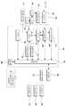
도 2는 본 발명에 따른 전기 굴삭기 시스템의 기능 구성을 나타내는 기능 블럭도이다.
도 3은 본 발명에 따른 전기 굴삭기 시스템에 적용되는 케이블 접속장치의 예시도이다.1 is an exemplary view of a conventional cable type electric excavator.
2 is a functional block diagram showing a functional configuration of the electric excavator system according to the present invention.
3 is an exemplary view of a cable connecting apparatus applied to the electric excavator system according to the present invention.
이하에서는, 첨부도면을 참고하여 본 발명에 따른 바람직한 실시예를 보다 상세하게 설명하기로 한다.Hereinafter, preferred embodiments of the present invention will be described in detail with reference to the accompanying drawings.
본 발명에 따른 전기 굴삭기 시스템은 앞서 설명한 종래 케이블식 전기 굴삭기의 개념을 가지면서 충전 개념을 포함하여 필요시 전력을 공급받아 충전하고, 작업시에는 충전된 전력을 사용하며, 작업에 필요한 전압을 확보하고 있는지를 검출하여 필요시 충전할 수 있도록 구성된다.The electric excavator system according to the present invention has the concept of the conventional cable type electric excavator described above, including the charging concept, and receives power when needed, uses charged power when working, and secures the voltage required for the work. It is configured to detect whether it is doing so and to charge it when necessary.
이와 관련하여, 본 발명에 따른 전기 굴삭기 시스템의 구성 블럭도를 보여 주는 도 2를 참조한다.In this regard, reference is made to FIG. 2, which shows a block diagram of an electric excavator system according to the invention.
도 2에 도시된 바와 같이, 본 발명에 따른 전기 굴삭기는 전력공급부(100)와 전력수신부(200)로 분리 구성된다.As shown in FIG. 2, the electric excavator according to the present invention includes a
이때, 전력공급부(100)는 기존처럼 외부에서 전원을 공급하는 장소에 설치되고, 전력수신부(200)는 굴삭기 본체에 설치된다.At this time, the
그리고, 상기 전력수신부(200)에는 상기 전력공급부(100)와 접속할 수 있도록 케이블커넥터(플러그와 소켓을 의미함)가 구비된다.In addition, the
보다 구체적으로, 도 2에 도시된 바와 같이, 전력공급부(100)는 전원박스(110)와, 케이블드럼(120), 케이블드럼(120)을 회전제어하는 드럼구동부(122), 케이블가이드(130), 길이검출부(140) 및 송신부(150)를 포함한다.More specifically, as shown in FIG. 2, the
이때, 상기 전원박스(110)는 다수의 컨트롤스위치를 구비하고 있으며, 외부전원이 연결되어 상기 전력수신부(200)와 접속시 외부전원으로부터 공급된 필요한 전력을 상기 전력수신부(200)로 공급할 수 있도록 설계되어 있다.In this case, the
또한, 상기 전력공급부(100)는 필요에 따라 복수로 설치될 수 있는데, 작업반경이 큰 경우 적정간격을 두고 다수 설치됨으로써 상기 전력수신부(200)를 통한 접속의 용이성을 제공하여 작업성을 더욱 높일 수 있다.In addition, the
그리고, 상기 케이블드럼(120)은 전원박스(110)를 통해 컨트롤된 전력을 송전하는 케이블(Cable)을 감거나 풀어 주면서 근거리는 물론 원거리까지 케이블 관리를 원활하게 하여 준다.In addition, the
이 경우, 상기 케이블드럼(120)은 동력원에 의해 구동될 수 있는데, 동력원으로는 구동모터를 들 수 있고, 또한 드럼구동부(122)에 의해 제어될 수 있다.In this case, the
아울러, 상기 케이블가이드(130)는 전력이 공급되는 케이블이 엉키거나 꼬이지 않도록 안내하도록 된 구조물로 도 1에 예시된 기존 케이블가이드 형태를 그대로 가질 수 있다.In addition, the
이 경우, 상기 케이블가이드(130)는 케이블이 권취된 케이블드럼(120)으로부터 인출된 케이블을 일정길이 범위까지 원활하게 인출될 수 있도록 안내한다.In this case, the
상기 길이검출부(140)는 케이블드럼(120)의 1회전 주기를 카운트하여 케이블의 인출 길이를 검출하는 엔코더 또는 케이블의 최대 또는 최소 인출 거리를 확인할 수 있도록 케이블에 부착된 자석을 감지하는 마그네틱 센서, 바코드 등의 광인식표시를 검출하는 광센서 등의 길이 감지센서로 구성된다.The
이 경우, 최대 인출 거리와 최소 인출 거리를 표시하기 위한 위치에는 서로 다른 수의 자석 또는 광인식표시를 형성하는 것에 의해 케이블의 최대 또는 최소 인출 거리를 산출한다.In this case, the maximum or minimum lead-out distance of the cable is calculated by forming different numbers of magnets or light recognition marks at positions for indicating the maximum lead-out distance and the minimum lead-out distance.
또한, 케이블의 최대 또는 최소 인출 거리를 감지한 경우 길이검출부(140)는 감지한 케이블의 최대 또는 최소 인출에 대한 신호를 드럼구동부(122)와 송신부(150)로 출력한다.In addition, when detecting the maximum or minimum withdrawal distance of the cable, the
드럼구동부(122)는 케이블의 최대 또는 최소 인출 신호를 수신하는 경우 케이블드럼(120)의 과도한 권취 또는 인출을 차단하여 케이블의 파손을 방지한다.The
뿐만 아니라, 상기 길이검출부(140)는 케이블의 최대 또는 최소 인출 신호를 송신한 후 케이블이 최대 또는 최소 인출 범위 내의 길이를 가지는 경우 케이블길이제한 해제 신호를 송신부(150)를 경유하여 수신부(201)로 전송하도록 구성된다.In addition, the
상기 송신부(150)는 길이검출부(140)에서 입력되는 케이블의 최대 또는 최소 인출 신호를 전력수신부(200)의 측의 수신부(201)로 송신하게 된다.The
이 경우, 송신부(150)와 수신부(201)는 무선통신을 수행하도록 구성되거나 케이블과 함께 구비되는 데이터 케이블을 통해 유선으로 연결 구성될 수도 있다.In this case, the
상술한 구성의 전력공급부(100)는 대한민국 공개특허 제2006-124455호에 개시된 바와 같이 지주의 상부에서 회전 가능하게 설치되는 작동간 등의 구성을 포함하는 형태로 구성될 수도 있다.The
여기에서, 상기 케이블가이드(130)를 거쳐 인출되는 케이블의 단부에는 도 3과 같은 케이블 접속장치를 구성하는 소켓(500)이 구비되고, 상기 소켓(500)에는 굴삭기측 전원케이블(310)에 연결된 플러그(400)가 접속될 수 있다.Here, the end of the cable drawn out through the
더욱 구체적으로, 상기 케이블 접속장치는 크게 플러그(400)와 소켓(500)으로 구성된다.More specifically, the cable connection device is largely composed of a
이때, 상기 플러그(400)는 굴삭기측에 구비되는 것으로 굴삭기의 전원케이블(310)이 결선된 상태를 유지하며, 선단에는 상기 전원케이블(310)의 내부에 구비된 도선과 연결된 도전접속구(410)가 마련되고, 상기 도전접속구(410)의 일부는 외피(420)에 의해 절연되며, 상기 외피(420)의 특정개소에는 상기 플러그(400)를 접속한 후 안전하게 고정하기 위한 볼트식 체결부재(430)가 구비된다.In this case, the
특히, 상기 도전접속구(410)는 선단을 향해 원뿔대 형태로 형성되도록 하여 접속의 용이성을 확보함이 더욱 바람직하다.In particular, the
그리고, 상기 소켓(500)은 상기 도전접속구(410)를 수용하는 부싱(510)과, 상기 부싱(510)의 일단으로부터 연장된 대략 원통형상의 단자접속부재(520)로 구성된다.The
아울러, 상기 단자접속부재(520)는 전원공급측 케이블과 연결된 상태에서 일정길이 유동가능하게 구비된 제1단자(522)를 내장하고, 상기 제1단자(522)와 간격을 두고 상기 단자접속부재(520) 내부에서 이탈되지 않고 유동되도록 구성되되 상기 도전접속구(410)와 접촉가능하도록 단자접속부재(520)로부터 노출되게 돌출된 제2단자(524)를 포함하는데, 이들 제1,2단자(522,524)는 대략 'ㅗ'형상을 갖지며, 평판인 부분이 서로 마주보게 단자접속부재(520) 내부에서 대향배치된다.In addition, the
한편, 상기 제1,2단자(522,524) 사이에는 원판 형상의 도전판(526)이 개재되며, 상기 제1,2단자(522,524) 각각은 스프링(530)에 의해 탄압된다.Meanwhile, a disc shaped
따라서, 상기 도전접속구(410)는 상기 제2단자(524)를 누르는 형태로 소켓(500)에 접속되고, 그러면 제2단자(524)가 눌리면서 도전판(526)을 사이에 두고 제1단자(522)와 탄성적으로 접촉되게 되어 항상 균일한 접촉을 유도할 수 있게 되어 안전하고 정확한 전기 접속을 유도할 수 있게 된다.Therefore, the
이때, 상기 소켓(500) 내부에는 필요에 따라 전압을 감지하는 전압탭(Voltage Tab)을 더 내장할 수 있다.In this case, the
뿐만 아니라, 상기 체결부재(430)는 도시된 예와 같은 볼트식이 아니라 퀵커플링 형태로 변형되면 더욱 좋다.In addition, the
한편, 전력수신부(200)는 유압 펌프 구동원인 엔진으로 전동기(230)를 포함하며, 상기 전동기(230)는 인버터(220)를 통해 직류 전원을 교류 전원으로 전환된 상태에서 교류 전원 형태로 전력을 공급받게 된다.Meanwhile, the
이때, 상기 인버터(220)는 컨트롤러(240)에 의해 제어된다.In this case, the
또한, 상기 전동기(230)에는 컨트롤러(240)를 통해 제어될 수 있도록 유압펌프(260)가 연결된다.In addition, the
아울러, 붐(Boom)을 탑재한 굴삭기 바디를 본체에 대해 360°회전시킬 수 있는 선회 전동발전기(232)도 더 포함한다.In addition, a
그리고, 선회 전동발전기(232)는 회생제동을 통해 전기에너지를 얻을 수 있도록 전동기 겸 발전기 형태를 취하고 있는데, 회생제동을 통해 얻어진 회생전기는 축전지(210)로 회수되어 축전된다.In addition, the turning
이와 같이, 회생제동을 통해 회생된 전기를 축전지(210)에 축전하여 사용할 수 있으므로 구동에 따른 열 발생을 줄이고, 에너지의 재활용이 가능한 장점을 가진다.As such, since the regenerative braking can be used to accumulate electricity to the
물론, 상기 선회 전동발전기(232)도 상기 컨트롤러(240)에 의해 제어된다.Of course, the
또한, 송신부(150)에서 전송된 케이블의 최대 또는 최소 인출 거리에 대한 신호를 수신한 후 이를 컨트롤러(240)로 출력하는 수신부(201)를 더 포함하여 구성된다.In addition, the
컨트롤러(240)는 수신부(201)로부터 케이블의 최대 또는 최소 인출 거리에 대한 신호를 수신하게 되면 알람부(250)로 경고 신호를 출력하여 작업자에게 경고를 수행하게 된다.When the
작업자는 케이블의 최대 인출 경고를 확인하는 경우에는 원거리 이동을 중지하고 전력공급부(100) 측으로 이동하거나, 케이블을 분리하게 된다.When the operator checks the maximum pull out warning of the cable, the operator stops the remote movement and moves to the
이와 달리 케이블의 최소 인출 경고를 확인하는 경우에는 전력공급부(100) 측으로의 이동을 중지하고 원거리로 이동하는 조작을 수행하게 된다.On the contrary, in the case of checking the minimum withdrawal warning of the cable, the operation of stopping the movement to the
이때, 작업자가 경고를 확인하지 못하고 일정 시간이 경과하면 컨트롤러(240)는 굴삭기의 구동을 정지시키도록 구성될 수도 있다.At this time, if a certain time elapses without the operator checking the warning, the
또한, 컨트롤러(240)는 수신부(201)로부터 케이블의 최대 또는 최소 인출 신호를 수신하여 알람 신호를 출력한 후 일정 시간이 경과한 후에 케이블 제한 길이 해제 신호가 없는 상태에서 굴삭기의 작업이 계속되는 경우 굴삭기의 구동을 정지시키도록 구성된다.In addition, the
나아가, 상기 컨트롤러(240)는 소정의 메모리를 포함할 수 있다.In addition, the
그리고, 상기 유압펌프(260)에는 유압제어밸브(270)가 접속되며, 유압펌프(260)에 의해 토출된 작동유는 상기 유압제어밸브(270)의 제어순서에 따라 붐 실린더(274), 아암 실린더(276), 버켓 실린더(278)를 구동하게 된다.In addition, a
즉, 유압펌프(260)의 구동까지만 전기적 결합으로 이루어져 있기 때문에 전동기(230)의 구동력을 선택적으로 전달받도록 컨트롤러(240)에 의해 제어되지만, 이후 유압펌프(260)의 구동으로 발생된 작동유의 공급과 관련된 유압회로는 유압제어밸브(270)의 개폐제어를 통해 기존처럼 이루어지는 것이다.That is, since only the drive of the
그리고, 상기 전동기(230)에 전력을 공급하는 축전지(210)가 구비되는데, 상기 축전지(210)는 직류형이기 때문에 앞서 설명하였듯이, 인버터(220)를 통해 전동기(230)로 직류 전원을 교류 전원으로 바꾸어 공급하게 된다.In addition, a
뿐만 아니라, 상기 축전지(210)는 앞서 설명한 플러그(400)와 소켓(500)의 접속을 통해 충전가능하게 구성되므로 적정량의 전원이 충전되어 있는 상태에서는 전력공급부(100)로부터 분리되어 전동기(230)를 구동할 수 있으므로 굴삭기의 작업범위를 자유롭게 할 수 있고 확장할 수 있다.In addition, since the
다만, 충전된 전력이 일정 이하로 떨어지게 되면 굴삭기의 작업을 수행하기 어려우므로 미리 확인한 후 굴삭기를 전력공급부(100) 지근거리로 주행한 후 재접속하여 충전함으로써 이를 해결할 수 있다.However, when the charged power falls below a certain level, it is difficult to perform the operation of the excavator, so after checking in advance, the excavator can be solved by reconnecting and charging after driving the
이를 위해, 본 발명에서는 상기 축전지(210)에 축전량검출부(214)를 더 설치하고, 동시에 과충전에 의한 축전지(210) 손상을 방지할 수 있도록 과충전방지부(212)도 더 포함하여 설치된다.To this end, in the present invention, the storage
이때, 상기 과충전방지부(212) 및 축전량검출부(214)는 모두 컨트롤러(240)와 연결되어 컨트롤러(240)에 의해 제어되도록 구성되는데, 이들 과충전방지부(212)와 축전량검출부는 과충전방지회로, 축전량검출회로 등과 같이 일종의 회로 형태를 갖는 것이 바람직하다.At this time, the
아울러, 상기 축전량검출부(214)는 축전지(210)의 잔존용량(SOC:State Of Charge) 및 온도에 따라 변화되는 내부저항을 검출하여 전위를 추정하는 방법 등 여러가지 방식으로 축전지(210)에 축전된 전기량, 즉 전위를 검출할 수 있는데 가장 간단한 방식인 축전지(210)의 양단 전압을 검출하고, 이를 컨트롤러(240)에 송신하며, 컨트롤러(240)는 수신된 검출전위를 구동에 필요한 기준전위와 비교하여 충전 여부를 확인하고 제어하도록 구성함이 바람직하다.In addition, the power
또한, 상기 컨트롤러(240)에는 알람부(250)가 연결된다.In addition, the
상기 알람부(250)는 굴삭기 운전자가 시청각적으로 확인할 수 있도록 경보음을 발하면서 경광등을 점멸시킬 수 있도록 구성된다.The
이러한 알람부(250)는 앞서 설명한 축전량검출부(214)의 축전지(210) 검출 전위가 기준전위에 미치지 못할 경우 컨트롤러(240)의 제어하에 동작되는 것으로, 이를 통해 운전자가 굴삭기를 전력공급부(100) 쪽으로 주행시켜 전력공급부(100)에 마련된 케이블을 전력수신부(200)에 접속함으로써 충전작업을 수행하도록 하기 위한 것이다.The
이러한 구성으로 이루어진 본 발명은 다음과 같은 작동관계를 갖는다.The present invention having such a configuration has the following operational relationship.
먼저, 작업반경이 전력공급부(100)로부터 멀지 않아 케이블의 길이 내에 있을 경우에는 굳이 전력공급부(100)와 전력수신부(200)를 분리할 필요없이 케이블커넥터를 통해 전력공급부(100)와 전력수신부(200)를 접속한 상태를 유지하면서 전기 굴삭기를 통해 할 수 있는 작업, 예컨대 굴삭작업, 브레이커작업, 크라샤작업 등 원하는 작업을 수행하게 된다.First, when the working radius is not far from the
이 경우에는 전력공급부(100)를 통해 전력이 지속적으로 공급되고 있는 상태이므로 동력(유압펌프 구동용)이 충분한 상태에서 큰 무리없이 작업이 가능하게 된다.In this case, since the power is continuously supplied through the
반면, 작업반경이 케이블 길이를 벗어나는 경우라면 전력공급부(100)로부터 충분한 전력을 공급받아 전력수신부(200)에 구비된 축전지(210)에 필요한 전력을 충분히 충전시킨다.On the other hand, if the working radius is out of the cable length is supplied with sufficient power from the
그리하여, 충전이 완료되면 케이블커넥터의 접속을 해제하여 전력공급부(100)와 전력수신부(200)가 분리되도록 한다.Thus, when charging is complete, the cable connector is disconnected so that the
이후, 굴삭기는 축전지(210)에 축전된 전력을 이용하여 유압펌프(260)를 구동하며, 작업 장소로 이동 후 콘트롤러(240)의 제어하에 필요로 하는 작업을 하게 된다.Thereafter, the excavator drives the
아울러, 작업중 알람부(250)를 통해 알람이 발생되면 운전자는 다시 굴삭기를 전력공급부(100) 쪽으로 주행하여 케이블커넥터를 접속함으로써 전력공급부(100)로부터 전력을 공급받아 축전지(210)에 충전하고, 충분한 축전이 이루어지면 다시 케이블을 분리한 다음 작업장소로 이동하여 작업하게 된다.In addition, when an alarm occurs through the
이때, 상기 전력공급부(100)를 작업반경에 맞춰 복수로 설치해 두면 충전을 위해 굴삭기가 이동하는 시간이 줄어들고, 그에 따라 충전시간도 줄어들게 되어 작업효율이 향상되는 장점을 갖게 된다.At this time, if a plurality of
이와 같이, 본 발명에 따른 전기 굴삭기는 축전지(210)를 활용하여 엔진을 대체한 전동기(230)를 구동시킴으로써 유압펌프(260)를 구동시켜 굴삭기가 수행할 수 있는 여러가지 작업을 할 수 있으므로 작업효율이 향상되고, 에너지를 절감하는 효과를 얻을 수 있다.As described above, the electric excavator according to the present invention can drive a
물론, 급속충전의 문제가 있으나, 이는 본 발명에서 다룰 범위에 속하지 않으며, 충전방법이나 축전지 구조 등에서 취급할 문제이므로 이에 대한 언급은 생략하였다.Of course, there is a problem of rapid charging, but this does not belong to the range to be covered in the present invention, it is omitted because it is a problem to be handled in the charging method or storage battery structure.
특히, 충전이 필요할 때 본 발명에 따른 플러그(400)와 소켓(500)을 이용하여 전력공급부(100)와 전력수신부(200)를 접속하게 되면 접속의 용이성을 확보함은 물론 항상 일정한 탄성력으로 균일한 접점을 유지하기 때문에 안정적이고 원활한 충전이 가능하게 된다.Particularly, when charging is required, when the
100 : 전력공급부 110 : 전원박스
120 : 케이블가이드 140: 길이검출부
150: 송신부
200 : 전력수신부 201: 수신부
210 : 축전지 220 : 인버터
230 : 전동기 232 : 선회 전동발전기
240 : 컨트롤러 250 : 알람부
260 : 유압펌프 270 : 유압제어밸브
400 : 플러그 500 : 소켓100: power supply unit 110: power box
120: cable guide 140: length detection unit
150: transmitter
200: power receiver 201: receiver
210: storage battery 220: inverter
230: electric motor 232: swing motor generator
240: controller 250: alarm unit
260: hydraulic pump 270: hydraulic control valve
400: plug 500: socket
Claims (3)
Translated fromKorean전원박스와 케이블드럼, 드럼구동부, 케이블가이드, 케이블드럼의 케이블의 인출 길이를 감지하는 길이검출부, 상기 길이검출부에서 검출된 케이블의 길이가 최대 또는 최소 인출 길이인 경우 이를 전력수신부 측으로 전송하는 송신부로 구성된 전력공급부와;
컨트롤러와 축전지, 과충전방지부, 축전량검출부, 인버터, 알람부, 상기 전력공급부의 송신부가 전송한 케이블의 최대 또는 최소 인출 신호를 수신한 후 알람의 출력 또는 구동 정지를 위한 컨트롤러로 출력하는 수신부로 구성된 전력수신부;를 구비하고,
상기 케이블의 단부에는 부싱과 부싱의 일단으로부터 연장된 원통형상의 단자접속부재로 구성된 소켓이 더 구비되며;
상기 굴삭기에 구비된 전원케이블의 단부에는 원뿔대 형태를 갖고 부싱에 삽입되는 도전접속구와 상기 도전접속구의 일부를 감싸는 외피로 구성된 플러그가 더 구비된 것을 특징으로 하는 전기 굴삭기 시스템.An electric excavator system comprising a power supply and a power receiver;
Power box, cable drum, drum drive unit, cable guide, the length detection unit for detecting the length of the cable out of the cable drum, if the length of the cable detected by the length detection unit is sent to the power receiving unit to send the maximum or minimum length A configured power supply unit;
After receiving the maximum or minimum withdrawal signal of the cable transmitted from the controller, the battery, the overcharge protection unit, the power storage detection unit, the inverter, the alarm unit, the transmission unit of the power supply to the controller for outputting the alarm or output to the controller for stopping the operation. A power receiver configured;
An end of the cable is further provided with a socket comprising a bushing and a cylindrical terminal connecting member extending from one end of the bushing;
The end of the power cable provided with the excavator has a truncated conical shape and a plug consisting of a conductive connector inserted into the bushing and the outer shell surrounding a portion of the conductive connector is further provided.
상기 길이검출부는 상기 케이블의 권취 또는 인출을 위해 회전되는 케이블드럼의 회전수를 카운트하여 케이블의 최대 또는 최소 인출 거리를 감지하는 엔코더 또는 케이블에 부착된 식별표시를 인식하는 길이센서 중 하나로 구성되는 것을 특징으로 하는 전기 굴삭기 시스템.The method according to claim 1;
The length detecting unit comprises one of an encoder for detecting the maximum or minimum drawing distance of the cable by counting the number of revolutions of the cable drum rotated for winding or drawing out the cable or a length sensor for recognizing an identification mark attached to the cable. An electric excavator system characterized by the above.
상기 단자접속부재에는 스프링을 통해 유동가능하며 케이블과 연결된 'ㅗ'형상의 제1단자, 제1단자와 간격을 두고 스프링에 의해 유동가능하며 도전접속구와 접촉되는 제2단자, 제1 및 제2 단자 사이에 개재된 도전판이 더 구비된 것을 특징으로 하는 전기 굴삭기 시스템.
The method according to claim 1;
The terminal connecting member is movable through a spring and has a 'ㅗ' -shaped first terminal connected to a cable, and second terminals, first and second, which are movable by a spring at a distance from the first terminal and in contact with a conductive connector. An electric excavator system further comprising a conductive plate interposed between the terminals.
Priority Applications (1)
| Application Number | Priority Date | Filing Date | Title |
|---|---|---|---|
| KR1020110032677AKR20120114869A (en) | 2011-04-08 | 2011-04-08 | Electric excavator system |
Applications Claiming Priority (1)
| Application Number | Priority Date | Filing Date | Title |
|---|---|---|---|
| KR1020110032677AKR20120114869A (en) | 2011-04-08 | 2011-04-08 | Electric excavator system |
Publications (1)
| Publication Number | Publication Date |
|---|---|
| KR20120114869Atrue KR20120114869A (en) | 2012-10-17 |
Family
ID=47283925
Family Applications (1)
| Application Number | Title | Priority Date | Filing Date |
|---|---|---|---|
| KR1020110032677ACeasedKR20120114869A (en) | 2011-04-08 | 2011-04-08 | Electric excavator system |
Country Status (1)
| Country | Link |
|---|---|
| KR (1) | KR20120114869A (en) |
Cited By (2)
| Publication number | Priority date | Publication date | Assignee | Title |
|---|---|---|---|---|
| US20210134481A1 (en)* | 2019-10-31 | 2021-05-06 | Commscope Technologies Llc | Cable jackets with magnetic attraction |
| KR102723588B1 (en)* | 2023-12-18 | 2024-10-30 | 주식회사 현대케피코 | Device and method for learning the length of a charging cable of an electric vehicle charging system |
- 2011
- 2011-04-08KRKR1020110032677Apatent/KR20120114869A/ennot_activeCeased
Cited By (2)
| Publication number | Priority date | Publication date | Assignee | Title |
|---|---|---|---|---|
| US20210134481A1 (en)* | 2019-10-31 | 2021-05-06 | Commscope Technologies Llc | Cable jackets with magnetic attraction |
| KR102723588B1 (en)* | 2023-12-18 | 2024-10-30 | 주식회사 현대케피코 | Device and method for learning the length of a charging cable of an electric vehicle charging system |
Similar Documents
| Publication | Publication Date | Title |
|---|---|---|
| KR101704829B1 (en) | Electric excavator system | |
| CN209748353U (en) | coal mine underground power generation device | |
| KR101388388B1 (en) | Electric vehicles and method of sub-battery charging thereof | |
| CN203434641U (en) | Wireless charging communication system for electric vehicles | |
| US11381122B2 (en) | Method for detecting a plug-in operation | |
| EP2879267B1 (en) | Contactless power-supply system | |
| CN104638696B (en) | For wireless charging system and method for the Mobile energy storage power station to new-energy automobile | |
| JP2013507901A (en) | Electric connection device for hybrid vehicle and electric vehicle, and charging method for hybrid vehicle and electric vehicle | |
| KR102114671B1 (en) | Common charger for charging electric vehicle and control method thereof | |
| BR112015028763B1 (en) | METHOD AND ARRANGEMENT FOR CHARGING CONTROL OF AN ENERGY STORAGE SYSTEM | |
| CN102355026A (en) | Backup energy-storage power supply managing system of coal mine electronic device | |
| KR20130049902A (en) | Electric excavator | |
| KR101635653B1 (en) | Electric excavator system | |
| KR20120114869A (en) | Electric excavator system | |
| CN105365581A (en) | Trolleybus trolley head structure | |
| CN109263503A (en) | Charging pile with vehicle vehicle interconnecting function | |
| KR20120114842A (en) | Electric excavator system | |
| KR20120114875A (en) | Electric excavator system | |
| EP3294585B1 (en) | Tracked vehicle, power supply apparatus for powering the tracked vehicle, and handling system in a work area comprising the tracked vehicle and power supply apparatus | |
| CN110790155A (en) | Bolt type crane arm and crane | |
| CN209650068U (en) | Charging pile with vehicle vehicle interconnecting function | |
| JP5351088B2 (en) | Auxiliary rechargeable batteries for electric vehicles and electric vehicles | |
| KR101507952B1 (en) | Electric excavator system | |
| KR20120111004A (en) | Electric excavator system | |
| KR102375840B1 (en) | Installation method of protection device for underground transmission line |
Legal Events
| Date | Code | Title | Description |
|---|---|---|---|
| PA0109 | Patent application | Patent event code:PA01091R01D Comment text:Patent Application Patent event date:20110408 | |
| PG1501 | Laying open of application | ||
| A201 | Request for examination | ||
| PA0201 | Request for examination | Patent event code:PA02012R01D Patent event date:20150710 Comment text:Request for Examination of Application Patent event code:PA02011R01I Patent event date:20110408 Comment text:Patent Application | |
| E902 | Notification of reason for refusal | ||
| PE0902 | Notice of grounds for rejection | Comment text:Notification of reason for refusal Patent event date:20161104 Patent event code:PE09021S01D | |
| E601 | Decision to refuse application | ||
| PE0601 | Decision on rejection of patent | Patent event date:20170314 Comment text:Decision to Refuse Application Patent event code:PE06012S01D Patent event date:20161104 Comment text:Notification of reason for refusal Patent event code:PE06011S01I |