KR20120111871A - Method and apparatus for creating medical image using 3d deformable model - Google Patents
Method and apparatus for creating medical image using 3d deformable modelDownload PDFInfo
- Publication number
- KR20120111871A KR20120111871AKR1020110086694AKR20110086694AKR20120111871AKR 20120111871 AKR20120111871 AKR 20120111871AKR 1020110086694 AKR1020110086694 AKR 1020110086694AKR 20110086694 AKR20110086694 AKR 20110086694AKR 20120111871 AKR20120111871 AKR 20120111871A
- Authority
- KR
- South Korea
- Prior art keywords
- image
- organ
- model
- images
- patient
- Prior art date
- Legal status (The legal status is an assumption and is not a legal conclusion. Google has not performed a legal analysis and makes no representation as to the accuracy of the status listed.)
- Withdrawn
Links
Images


Classifications
- A—HUMAN NECESSITIES
- A61—MEDICAL OR VETERINARY SCIENCE; HYGIENE
- A61B—DIAGNOSIS; SURGERY; IDENTIFICATION
- A61B34/00—Computer-aided surgery; Manipulators or robots specially adapted for use in surgery
- A61B34/10—Computer-aided planning, simulation or modelling of surgical operations
- A—HUMAN NECESSITIES
- A61—MEDICAL OR VETERINARY SCIENCE; HYGIENE
- A61B—DIAGNOSIS; SURGERY; IDENTIFICATION
- A61B34/00—Computer-aided surgery; Manipulators or robots specially adapted for use in surgery
- A61B34/10—Computer-aided planning, simulation or modelling of surgical operations
- A61B2034/101—Computer-aided simulation of surgical operations
- A61B2034/105—Modelling of the patient, e.g. for ligaments or bones
Landscapes
- Health & Medical Sciences (AREA)
- Surgery (AREA)
- Engineering & Computer Science (AREA)
- Life Sciences & Earth Sciences (AREA)
- Medical Informatics (AREA)
- Robotics (AREA)
- Biomedical Technology (AREA)
- Heart & Thoracic Surgery (AREA)
- Nuclear Medicine, Radiotherapy & Molecular Imaging (AREA)
- Molecular Biology (AREA)
- Animal Behavior & Ethology (AREA)
- General Health & Medical Sciences (AREA)
- Public Health (AREA)
- Veterinary Medicine (AREA)
- Ultra Sonic Daignosis Equipment (AREA)
- Magnetic Resonance Imaging Apparatus (AREA)
- Measuring And Recording Apparatus For Diagnosis (AREA)
Abstract
Translated fromKoreanDescription
Translated fromKorean3차원적 모델을 이용한 신체 장기의 영상을 생성하는 방법과 장치에 관한 것이다.A method and apparatus for generating an image of a body organ using a three-dimensional model.
질병치료에 있어서 환자의 진단과 치료의 전통적인 방법은 외과적 수술을 통하여 개복 후 육안으로 발병상태를 확인하고 거대한 수술용 기구를 이용하여 병변에 대해 절개와 성형을 가하는 방법이었다. 하지만 최근 의료기술의 발달로 인해 높은 해상도의 의료영상을 얻을 수 있고 의료 기구의 미세한 조작이 가능해 짐에 따라서, 인체의 직접적인 절개를 하지 않고도 피부에 작은 구멍을 만든 뒤 혈관 혹은 기타 원하는 신체 부위에 직접 카테터나 의료용 바늘을 넣고 의학 영상 장비로 몸속을 관찰하면서 치료하는 방법이 개발되고 있다. 이를 "영상을 이용하는 시술법", "인터벤션(Interventional) 영상 시술법" 또는 "중재적 영상 시술법"이라고 부른다. 시술자는 장기나 병변의 위치를 영상을 통해 파악한다. 게다가 시술을 하는 동안 환자는 호흡을 하거나 움직이게 되는데 이에 따른 변화를 파악해야한다. 따라서 시술자는 실시간 영상을 토대로 호흡이나 움직임을 정확하고 빠르게 파악하여 시술을 시행해야 하는데, 이 때 실시간 영상에서 장기와 병변의 형상을 육안으로 파악하기 쉽지 않다. 따라서 이를 해결하기 위해 시술자에게 실시간으로 장기의 형상 및 위치를 알려주는 방법 및 장치들이 등장하고 있다.The traditional method of diagnosing and treating patients in the disease treatment method is to visually check the incidence after open surgery through surgical operation, and to incision and shape the lesion using a huge surgical instrument. However, with the recent development of medical technology, it is possible to obtain high resolution medical images and to make fine manipulations of medical instruments. Thus, small holes are made in the skin without direct incision of the human body, and then directly into blood vessels or other desired body parts. A method of inserting a catheter or medical needle and observing the body with medical imaging equipment is being developed. This is referred to as "a procedure using an image", "interventional image procedure" or "intermediate image procedure". The practitioner determines the location of the organ or lesion through the image. In addition, during the procedure, the patient breathes or moves, and the change should be noted. Therefore, the operator should perform the procedure by accurately and quickly grasp the breathing or movement based on the real-time image, at this time it is not easy to grasp the shape of the organs and lesions in the real-time image. Therefore, in order to solve this problem, methods and devices for informing the operator of the shape and location of organs in real time have emerged.
환자의 실시간 의료 영상에서 장기의 빠르고 정확한 추적에 적합한 영상을 생성하는 방법 및 장치를 제공하는데 있다. 또한, 상기 방법을 컴퓨터에서 실행시키기 위한 프로그램을 기록한 컴퓨터로 읽을 수 있는 기록 매체를 제공하는데 있다. 본 실시예가 이루고자 하는 기술적 과제는 상기된 바와 같은 기술적 과제들로 한정되지 않으며, 또 다른 기술적 과제들이 존재할 수 있다.The present invention provides a method and apparatus for generating an image suitable for fast and accurate tracking of an organ from a real-time medical image of a patient. It is still another object of the present invention to provide a computer-readable recording medium on which a program for executing the above method on a computer is recorded. The technical problem to be solved by this embodiment is not limited to the above-described technical problems, and other technical problems may exist.
본 발명의 일 측면에 따른 신체 장기의 추적 방법은 상기 적어도 하나의 장기를 나타내는 의료 영상에 기초하여 상기 적어도 하나의 장기의 3차원 모델을 생성하는 단계, 상기 환자의 신체 활동에 따른 상기 적어도 하나의 장기의 형태적 변화를 나타내는 복수 개의 영상들과 상기 장기의 3차원 모델을 정합함으로써 복수 개의 정합 영상들을 생성하는 단계, 상기 환자의 현재 신체 상태에 기초하여 상기 정합 영상들 중 어느 하나를 선택하여 출력하는 단계를 포함한다.According to an aspect of the present invention, there is provided a method of tracking a body organ, the method including generating a three-dimensional model of the at least one organ based on a medical image representing the at least one organ, wherein the at least one of the at least one organ according to the physical activity of the patient. Generating a plurality of registration images by matching a plurality of images representing a morphological change of an organ with a three-dimensional model of the organ, selecting and outputting any one of the registration images based on a current physical condition of the patient It includes a step.
본 발명의 다른 측면에 따라 상기된 신체 장기의 추적 방법을 컴퓨터에서 실행시키기 위한 프로그램을 기록한 컴퓨터로 읽을 수 있는 기록매체가 제공된다.According to another aspect of the present invention, there is provided a computer-readable recording medium having recorded thereon a program for executing the above-described method of tracking a body organ in a computer.
본 발명의 또 다른 측면에 따른 신체 장기의 추적 장치는 적어도 하나의 장기를 나타내는 의료 영상을 기초로 상기 적어도 하나의 장기의 3차원 모델을 생성하는 장기 모델 생성부, 환자의 신체 활동에 따른 적어도 하나의 장기의 형태적 변화를 나타내는 복수 개의 영상들과 상기 장기의 3차원 모델을 정합한 영상을 생성하는 영상 정합부, 상기 환자의 현재 신체 상태에 기초하여 상기 정합 영상들 중 어느 하나를 선택하는 영상 검색부를 포함한다.In accordance with another aspect of the present invention, an apparatus for tracking a body organ includes an organ model generator configured to generate a 3D model of the at least one organ based on a medical image representing at least one organ, and at least one according to a physical activity of a patient. An image matching unit generating a plurality of images representing a morphological change of an organ and an image of the 3D model of the organ, and selecting one of the matching images based on a current physical state of the patient It includes a search unit.
상기된 바에 따르면, 실시간으로 출력되는 의료 영상에 그래픽적인 장기의 모델을 합성하여 출력하므로써, 중재적 시술시 장기의 위치를 정확하게 빠르게 추적할 수 있다.As described above, by synthesizing and outputting a graphic organ model to a medical image output in real time, it is possible to accurately and accurately track the position of the organ during the interventional procedure.
도 1은 본 발명의 일 실시예에 따른 신체 장기 영상 생성 시스템의 구성도이다.
도 2은 도 1에 도시된 영상 정합 장치(20)의 구성도이다.
도 3은 평균 모델 생성부(202)에서의 장기 경계와 내부 구조의 위치 좌표 정보를 추출하는 과정의 일례를 도시한 도면이다.
도 4는 영상 정합부(204)가 각 영상 별로 장기의 변형을 반영된 개인화 모델을 초음파 영상에서의 장기의 위치와 일치시키는 과정의 흐름도를 나타낸 것이다.
도 5는 2차원 영상에서 어파인 변환함수(Taffine)를 획득하는 일례를 도시한 도면이다.
도 6는 영상 정합부(204)가 영상을 정합(match)하는 과정을 도시한 도면이다.
도 7는 횡격막의 절대적인 위치의 상하 이동 그래프를 나타낸다.
도 8은 3차원적 장기 모델 기반의 동적 장기와 병변 추적 방법의 전체적인 흐름도를 나타낸 것이다.1 is a block diagram of a body organ image generation system according to an embodiment of the present invention.
FIG. 2 is a configuration diagram of the image matching
FIG. 3 is a diagram illustrating an example of a process of extracting long-term boundary and position coordinate information of an internal structure in the
FIG. 4 is a flowchart illustrating a process in which the
FIG. 5 illustrates an example of obtaining anaffine transform function Taffine from a 2D image.
FIG. 6 is a diagram illustrating a process of matching an image by the
7 shows a graph of vertical movement of the absolute position of the diaphragm.
Figure 8 shows the overall flow diagram of the dynamic organ and lesion tracking method based on the three-dimensional organ model.
이하, 첨부된 도면을 참조하여 본 발명의 실시예들을 상세히 설명한다.Hereinafter, embodiments of the present invention will be described in detail with reference to the accompanying drawings.
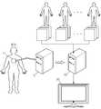
도 1은 본 발명의 일 실시예에 따른 신체 장기 영상 생성 시스템의 구성도이다. 도 1을 참조하면, 도 1에 도시된 실시예에 따른 신체 장기 영상 생성 시스템은 영상 검출 장치(10), 영상 정합 장치(20), 영상 표시 장치(30)로 구성된다. 영상 검출 장치(10)는 이것에 장착된 프로브(probe)(11)로부터 발생된 소스 신호(source signal)가 의사 등과 같은 의료 전문가가 진단하고자 하는 환자 신체의 특정 부위에 전달됨으로써 발생되는 반응을 이용하여 영상 데이터를 생성한다. 여기에서 소스 신호는 초음파, X선 등 여러 가지 신호가 될 수 있다. 영상 검출 장치(10)가 초음파(ultrasound)를 이용하여 환자 신체로부터 3차원 영상을 검출하는 초음파 진단기(ultrasonography machine)인 경우를 예를 들어 설명하면 다음과 같다.1 is a block diagram of a body organ image generation system according to an embodiment of the present invention. Referring to FIG. 1, the body organ image generating system according to the exemplary embodiment illustrated in FIG. 1 includes an
초음파 진단기에서의 프로브(11)는 일반적으로 압전 변환기(piezoelectric transducer)로 제조된다. 영상 검출 장치(10)의 프로브(11)로부터 2 ~ 18 MHz 범위의 초음파가 환자 신체 내부의 특정 부위에 전달되면, 이 초음파는 여러 다른 조직들(tissues) 사이의 계층들로부터 부분적으로 반사된다. 특히, 초음파는 신체 내부에서의 밀도 변화가 있는 곳, 예를 들어, 혈장(blood plasma) 내의 혈구들(blood cells), 장기들(organs) 내의 작은 조직들(structures) 등에서 반사된다. 이와 같이 반사된 초음파들은 프로브(11)의 압전 변환기를 진동시키고, 압전 변환기는 이 진동들에 따른 전기적 펄스들(electrical pulses)을 출력한다. 이와 같은 전기적 펄스들이 영상으로 변환된다.The
영상 검출 장치(10)는 2차원적인 영상을 출력할 수도 있지만, 3차원적인 영상도 출력할 수 있다. 영상 검출 장치(10)가 3차원적 영상을 출력하는 방법은 다음과 같다. 환자 신체 위에서 프로브(11)의 위치(location)와 방향(orientation)을 변화시키면서, 환자 신체의 특정 부위에 대한 다수의 단면 영상들을 검출한다. 이어서, 영상 검출 장치(10)는 이와 같은 단면 영상들을 축적하여 환자 신체의 특정 부위를 3차원적으로 나타내는 3차원 볼륨(volume)의 영상 데이터를 생성한다. 이와 같이 단면 영상들을 축적하여 3차원 볼륨의 영상 데이터를 생성하는 방식을 MPR(Multiplanar reconstruction) 방식이라고 한다.The
그런데, 이와 같이 영상 검출 장치(10)에 의해 얻을 수 있는 영상, 예를 들면 초음파 영상들은 실시간 영상을 얻을 수 있다는 장점이 있으나, 장기의 윤곽, 내부 구조나 병변을 명확하게 식별해내기가 어렵다는 단점이 있다.By the way, the image obtained by the
한편, CT(computed tomography)영상 이나 MR(magnetic resonance)영상의 경우에는 장기의 위치나 병변의 위치가 명확하게 구별이 되는 장점이 있다. 하지만 CT(computed tomography)영상 이나 MR(magnetic resonance)영상은 시술하는 동안 환자가 호흡을 하거나 뒤척일 때 장기가 변형되거나 위치가 변할 수 있는데 상기 실시간적인 변화를 반영한 영상을 얻을 수 없는 단점이 있다. 실시간으로 영상을 출력할 수 없는 각각의 이유는 CT(computed tomography)영상의 경우 방사선을 이용한 촬영방법이기 때문에 환자와 시술자가 장시간 방사능에 노출될 우려가 있기 때문에 짧은 시간의 촬영이 권장되며, MR(magnetic resonance)영상의 경우 한번 촬영하는데 시간이 오래 걸리기 때문이다.On the other hand, in the case of a computed tomography (CT) image or a magnetic resonance (MR) image, there is an advantage in that the location of an organ or a lesion is clearly distinguished. However, a CT (computed tomography) image or a magnetic resonance (MR) image may deform or change an organ when the patient breathes or retracts during the procedure. However, there is a disadvantage in that an image reflecting the real-time change cannot be obtained. The reason for not being able to output the image in real time is that the CT (computed tomography) image is a radiographic imaging method. Therefore, a short time recording is recommended because the patient and the operator may be exposed to radiation for a long time. Magnetic resonance images take a long time to shoot once.
이에 따라, 실시간으로 촬영이 가능함과 동시에 장기의 윤곽, 내부 구조나 병변을 명확하게 식별해내는 방법 및 장치가 요구된다. 따라서 이하에서 설명될 실시예들은 실시간으로 검출된 영상들에서 장기 및 병변의 모델을 정합(match)한 영상을 출력하여 실시간 영상에서 장기 및 병변의 정확한 위치나 변형을 식별할 수 있는 방법을 제시한다.Accordingly, there is a need for a method and apparatus capable of real-time imaging and clearly identifying the outline, internal structure, and lesion of an organ. Therefore, embodiments to be described below provide a method of identifying an exact position or deformation of organs and lesions in a real-time image by outputting an image matching the model of organs and lesions in the images detected in real time. .
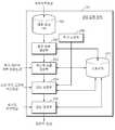
도 2은 도 1에 도시된 영상 정합 장치(20)의 구성도이다. 도 2를 참조하면, 도 1에 도시된 영상 정합 장치(20)는 의료 영상 DB(201), 평균 모델 생성부(202), 개인화 모델 생성부(203), 영상 정합부(204), 영상 검색부(205), 추가 조정부(206), 및 스토리지(207)로 구성된다.FIG. 2 is a configuration diagram of the image matching
평균 모델 생성부(202)는 다양한 개인의 의료 영상을 입력받아 이를 처리하므로써 대상 장기의 평균적인 모델을 출력한다. 본 발명에서는 환자 개인화된 모델을 생성하여 장기를 추적하는데, 여기서 평균적인 모델을 생성하는 단계는 개인화된 모델을 생성하기 위한 준비단계이다. 왜냐하면 개인에 따라서 장기의 형태, 크기, 특징 등 다양성이 있어서, 정확한 시술환경을 제공하기 위해서는 환자 개인의 특성을 반영할 필요가 있기 때문이다. 한편, 정확한 평균적인 모델을 얻기 위해서는 다양한 개인의 영상 정보가 활용될 수 있다. 또한 각 개인에서 얻은 영상도, 호흡에 따라서 변하는 장기의 형태를 반영하기 위해 다양한 호흡에서의 영상을 얻을 수 있다.The
구체적으로 우선 평균 모델 생성부(202)는 다양한 개인의 장기 형태, 크기 등을 분석하기 위해서 의료 전문가가 환자의 진단을 위해 촬영한 영상(이하, 외부의료영상이라 한다.)을 촬영기구로부터 직접 또는 영상이 저장된 저장매체로부터 입력받는다. 따라서 장기와 병변의 윤곽이나 장기 내부 특징의 분석이 용이한 영상을 입력받는 것이 바람직하다. 이를테면 CT(computed tomography) 혹은 MR(magnetic resonance)영상이 입력될 수 있다.In detail, the
외부 영상을 입력받는 다른 방법으로는 의료 영상 DB(201)에 의해서 상기 외부의료영상이 데이터화 되어 저장된 영상을 불러올 수 있다. 의료 영상 DB(201)에는 상기 외부의료영상이 다양한 개인에게서 촬영장치로부터 촬영되어 저장이 되어질 수도 있고, 저장매체로부터 입력받을 수도 있다. 의료 영상 DB(201)로부터 영상을 불러올 때에는 영상 전부를 불러올 수도 있고 사용자의 선택에 따라 일부를 불러올 수도 있다.As another method of receiving an external image, the external medical image may be converted into a data stored by the
하나의 실시예로 평균 모델 생성부(202)는 입력받은 외부의료영상을 기초로 3차원 ASM(active shape models) 알고리즘을 적용시킬 수 있다. 상기 알고리즘을 적용시키기 위해서 우선 상기 외부의료영상을 분석하여 각 외부의료영상에서 장기의 형태, 크기, 해부학적 특징을 추출하고, 이를 평균을 내서 통계적으로 평균을 낸 모델을 생성한다. ASM(active shape models) 알고리즘은 1994년에 발표된 "The Use of Active Shape Models For Locating Structure in Medical Images" (T.F.Cootes, A.Hill, C.J.Taylor and J.Haslam 저)에 자세한 설명이 나와있다. ASM(active shape models) 알고리즘을 적용하면 평균적인 장기의 형상을 얻을 수 있는데, 이 평균적인 장기 형상은 변수를 조정할 경우 그 형태를 변형 시킬 수 있다.In one embodiment, the
도 3은 평균 모델 생성부(202)가 상기 외부의료영상을 분석하는 과정으로써, 상기 입력된 CT(computed tomography) 혹은 MR(magnetic resonance)영상의 장기 경계와 내부 구조의 위치 좌표 정보를 추출하는 개략적인 방법을 도시한 것이다. 평균 모델 생성부(202)는 CT(computed tomography) 혹은 MR(magnetic resonance)영상이 입력되면, 장기 경계와 내부 구조의 위치 좌표 정보를 추출할 때 2차원 영상일 경우와 3차원 영상일 경우 다른 방식으로 진행된다. 여기서 내부 구조란, 간을 예로 들면 간동맥, 간정맥, 간문맥과 간관의 위치 등이 있을 수 있으며 이들의 경계값도 포함될 수 있다.3 is a process in which the
2차원 영상의 입력을 받을 경우 3차원 모델을 생성하기 위해서는 다수의 단면 영상들을 축적하여 대상 부위를 3차원적으로 나타내는 3차원 볼륨(volume)의 영상 데이터를 얻게 되는데, 이 과정은 도 3에서 왼쪽 부분에 여러 영상 정보가 축적되어 3차원 볼륨(volume)영상을 얻는 방법을 도시된 부분이다. 축적하기 전 다수의 단면 영상에서의 장기 경계와 내부 구조의 위치 좌표 정보를 추출한 후 축적하는 방향 축의 좌표 정보를 추가해 3차원 좌표 정보를 얻을 수 있는데, 도 3의 오른쪽 부분에 나타나 있는 영상은 z축의 값이 1인 영상이므로 상기 영상에서 추출되는 경계 위치 좌표 값의 z는 항상 1이다. 따라서 왼쪽 영상 데이터의 단면에서의 좌표 정보를 추출하는데 이는 2차원의 좌표 정보이므로 x,y축의 데이터로 나타 내어지지만, z축의 좌표 정보까지 포함하여 [x,y,1]의 좌표로 경계의 위치 좌표 정보를 추출한다. 그러면 상기 좌표 정보는 x,y,z축의 좌표를 포함한 정보일 것이다. 3차원 영상이 입력될 경우에는 소정의 간격으로 3차원 영상의 단면을 추출한 후 2차원 영상이 입력된 경우와 같은 과정을 거치게 되면 장기 경계와 내부 구조의 위치 좌표 정보를 얻을 수 있다. 이 과정에서의 2차원 영상에서 경계 위치 좌표의 추출은 알고리즘에 의한 자동/반자동적으로 얻을 수 있으며, 사용자가 출력된 영상 정보를 보고 수동적으로 좌표 정보를 입력 받을 수도 있다. 자동으로 경계의 좌표 정보를 얻는 방법을 예를 들면, 영상에서 밝기가 급변하게 변하는 지점의 좌표 정보를 얻을 수 있으며, DTFT(discrete time fourier transform)을 이용하여 주파수값이 가장 큰 위치를 경계라고 추출할 수 있다. 반자동적인 방법은 사용자에 의해 영상에서 일부 경계지점에 대한 정보를 입력받으면, 상기 경계지점을 기초로하여 상기 자동으로 좌표를 얻는 방법과 동일하게 주변의 경계를 추출할 수 있다. 장기의 경계는 연속적이며 폐곡선 형태를 이루기 때문에, 상기 성질을 이용하여 장기 경계 전체에 대한 정보를 얻을 수 있다. 이렇게 반자동인 방법은 영상 전체를 검색하지 않아도 되기 때문에 자동적인 경우보다 더 빠르게 결과를 얻을 수 있다. 수동적으로 얻을 때에는 사용자가 영상을 보면서 직접 경계의 좌표를 지정할 수 있는데, 이 때 지정하는 간격은 연속적일 수 없으므로, 중간에 불연속적인 구간은 보간(interpolation)을 통해 연속적으로 경계를 추출할 수 있다. 상기 기재된 방법으로 얻은 장기와 병변의 위치 좌표 정보는 3차원 공간에서 상기 좌표에 해당하는 복셀에서의 밝기값을 소정의 값으로 설정한 후 출력한다면 사용자가 3차원 그래픽적으로 표현된 장기와 내부 구조의 모습을 확인할 수 있다. 예를 들면 대상 장기 경계 좌표의 밝기값을 최소, 즉 가장 어두운 값으로 설정한다면 출력되는 영상에서 대상 장기의 영상은 검은 형태로 출력될 것이며, 대상 장기의 밝기를 흰색과 검은색의 중간값으로 설정하고 병변의 좌표의 밝기를 검은색으로 설정한다면 대상 장기와 병변을 쉽게 육안으로 구분할 수 있다. 상기 방법으로 얻은 복수의 장기 경계와 내부 구조의 위치 좌표 정보를 데이터 세트라고 정하고 3차원 ASM(active shape models) 알고리즘을 활용하기 위한 정보로 활용할 수 있다. 이하 ASM(active shape models) 알고리즘에 대해서 설명한다.In order to generate a three-dimensional model when receiving a two-dimensional image, a plurality of cross-sectional images are accumulated to obtain three-dimensional volume of image data that three-dimensionally represent a target region. This is a part showing a method of obtaining a three-dimensional volume image by accumulating various image information in the portion. Three-dimensional coordinate information can be obtained by extracting the coordinate information of the direction axis to accumulate after extracting the position coordinate information of the long-term boundary and the internal structure from a plurality of cross-sectional images before accumulation, the image shown in the right part of FIG. Since the value is 1, z of the boundary position coordinate value extracted from the image is always 1. Therefore, the coordinate information is extracted from the cross section of the left image data. Since it is two-dimensional coordinate information, it is represented by the data of x and y axes, but the coordinate information of [x, y, 1] including the coordinate information of z axis is included. Extract position coordinate information. Then the coordinate information will be information including the coordinates of the x, y, z axis. When the 3D image is input, the cross section of the 3D image is extracted at predetermined intervals, and then the same process as the case where the 2D image is input may be performed to obtain information about organ coordinates and position coordinates of the internal structure. In this process, the boundary position coordinates may be extracted automatically or semi-automatically by the algorithm, and the user may receive the coordinate information manually by viewing the output image information. For example, the coordinate information of the boundary can be automatically obtained. For example, the coordinate information of the point where the brightness suddenly changes in the image can be obtained, and the position having the largest frequency value is extracted as the boundary using the discrete time fourier transform (DTFT). can do. In the semi-automatic method, when the user receives information on some boundary points in the image, the boundary of the surroundings may be extracted in the same manner as the method of automatically obtaining coordinates based on the boundary points. Since the boundaries of organs are continuous and form a closed curve, the above properties can be used to obtain information about the entire organ boundaries. This semi-automatic method eliminates the need to search the entire image, resulting in faster results than automatic. When obtaining manually, the user can directly specify the coordinates of the boundary while viewing the image. In this case, since the intervals that are specified cannot be continuous, the discontinuous sections in the middle can be continuously extracted through interpolation. The position coordinate information of the organs and lesions obtained by the above-described method may be outputted after setting the brightness value in the voxel corresponding to the coordinates in a three-dimensional space to a predetermined value and then outputting the organs and the internal structure represented by the three-dimensional graphic. You can check the appearance. For example, if the brightness value of the target organ boundary coordinate is set to the minimum, that is, the darkest value, the image of the target organ will be output in black in the output image, and the brightness of the target organ is set to the middle value between white and black. If the brightness of the coordinates of the lesion is set to black, the target organ and the lesion can be easily distinguished by the naked eye. The position coordinate information of the plurality of organ boundaries and internal structures obtained by the above method may be designated as a data set and used as information for utilizing a three-dimensional active shape models (ASM) algorithm. Hereinafter, the ASM (active shape models) algorithm will be described.
ASM(active shape models) 알고리즘을 적용하기 위해서는 복수의 장기 경계와 내부 구조의 위치 좌표 정보의 좌표축을 일치시킨다. 좌표축을 일치시킨다는 것은 복수개의 대상체의 무게 중심을 하나의 원점으로 일치시키고 여러가지 다양한 형태에 대해 모든 장기의 방향을 정렬시킴을 의미한다. 그 후, 복수의 장기 경계와 내부 구조의 위치 좌표 정보에서 특징점(Landmark point)이 되는 지점을 결정한다. 특징점(Landmark point)이란 알고리즘을 적용시키기 위한 기본적인 지점을 말한다. 특징점(Landmark point)은 아래와 같은 방법으로 결정한다.In order to apply the ASM (active shape models) algorithm, a plurality of long-term boundaries coincide with coordinate axes of position coordinate information of an internal structure. Matching the coordinate axes means matching the center of gravity of a plurality of objects to one origin and aligning the orientation of all organs for various different forms. Thereafter, a point that becomes a feature point is determined from the position coordinate information of the plurality of organ boundaries and the internal structure. A feature mark is a basic point for applying an algorithm. The feature mark (Landmark point) is determined by the following method.
1. 대상의 특징이 뚜렷하게 반영된 지점을 특징점(Landmark point)으로 정한다. 예를 들면, 간의 경우 모든 사람이 공통적으로 갖고 있는 혈관이 나누어 지는 지점 또는 심장의 경우 우심방과 좌심방이 나뉘는 경계, 대정맥과 심장의 외벽이 만나는 경계 등이 있다.1. Set the point where the feature of the object is clearly reflected as the landmark mark. For example, in the liver, the blood vessels that all people have in common are divided, or in the heart, the boundary between the right atrium and the left atrium, and the border between the vena cava and the outer wall of the heart.
2. 정해진 좌표계에서 대상체의 가장 높은 지점, 혹은 가장 낮은 지점을 특징점(Landmark point)으로 정한다.2. Set the highest point or the lowest point of the object in the defined coordinate system as the landmark mark.
3. 상기 1.과 2.에서 정한 점들간의 사이를 보간(interpolation)할 수 있는 지점을 소정의 일정한 간격으로 경계를 따라 특징점(Landmark point)으로 지정한다.3. A point that can interpolate between the points defined in 1. and 2. is designated as a landmark mark along a boundary at predetermined constant intervals.
지정된 특징점은 2차원일 경우 x,y축의 좌표로, 3차원일 경우 x,y,z축의 좌표로 나타낼 수 있다. 따라서 3차원일 경우 각각의 특징점 좌표를 벡터로

아래첨자 i는 i번째 영상에서 얻은 장기 경계와 내부 구조의 위치 좌표 정보를 뜻한다. 상기 위치 좌표 정보는 경우에 따라서 그 갯수가 많아질 수 있는데 이의 연산을 용이하게 하기 위해서 하나의 벡터로 표현할 수 있다. 그러면 특징점 전체를 하나의 벡터로 나타낸 특징점 벡터를 수학식 2로 정의할 수 있다.The subscript i denotes the location coordinate information of the organ boundary and the internal structure obtained from the i-th image. The number of position coordinate information may be increased in some cases, but may be expressed as a vector to facilitate the calculation. Then, the feature point vector representing the entire feature point as one vector may be defined by Equation 2.

xi벡터의 크기는
데이터 세트의 갯수를 N개라고 할 때 세트 전체에 대해 특징점의 평균을 아래의 수학식 3으로 나타낼 수 있다.When the number of data sets is N, an average of feature points for the entire set may be represented by Equation 3 below.

마찬가지로

평균 모델 생성부(202)는 수학식 3을 계산하면 평균적인 특징점인
아래의 수학식 4에 의해서 특징점의 평균과 각 데이터의 차이를 나타낼 수 있다. 수학식 4에서 아래첨자 i는 i번째 영상을 뜻한다. 따라서 수학식 4는 각 영상에서의 특징점이 전체 영상의 평균과의 차이를 뜻한다.Equation 4 below can represent the difference between the average of the feature points and each data. In Equation 4, the subscript i denotes the i-th image. Therefore, Equation 4 means that the feature point in each image is different from the average of the entire image.

각 데이터의 차이를 이용하여 수학식 5에 의해 세 변수 x,y,z에 대한 공분산 행렬(covariance matrix)을 정의할 수 있다. 상기 공분산 행렬(covariance matrix)을 구하는 이유는 ASM(active shape models) 알고리즘을 적용하기 위한 복수개의 파라미터에 대한 아이겐벡터(unit eigen-vector)를 구하기 위함이다. (자세한 내용은 상기 논문에 기재되어 있음.)Covariance matrixes for three variables x, y, and z may be defined by Equation 5 using the difference of each data. The reason for obtaining the covariance matrix is to obtain unit eigen-vectors for a plurality of parameters for applying an active shape models (ASM) algorithm. (Details are given in the paper above.)

공분산 행렬(covariance matrix) S의 단위 아이겐벡터(unit eigen-vector)를


(
그러면 최종적으로 변형을 적용한 특징점 벡터


여기서


평균 모델 생성부(202)는 상기 과정의 수학식들 계산을 통해서 평균적인 모델의 형태를 뜻하는


개인화 모델 생성부(203)는 평균 모델 생성부(202)로부터 평균적인 장기 모델(


개인화 모델 생성부(203)는 CT(computed tomography) 혹은 MR(magnetic resonance)영상과 같이 장기의 형상을 뚜렷하게 파악할 수 있는 영상을 기초로 환자 개인의 ASM(active shape models) 알고리즘의 아이겐벡터의 비중값(벡터b)을 결정하는 것이다. 따라서 우선 환자 개인의 외부의료영상을 입력받아 장기 경계와 내부 구조의 위치 좌표 정보를 파악한다. 이 때는 상기 평균 모델 생성부(202)가 상기 외부의료영상을 분석하는 과정와 같이 도 3의 과정으로 파악한다. 게다가 상기 알고리즘을 처음 적용할 때 특징점(Landmark point)을 파악한 방법과 같은 과정으로 특징점(Landmark point) 좌표 정보를 파악하면 환자 개인화된 특징점 집합인 벡터


한편, 평균 모델 생성부(202) 의해서 결정된 벡터
영상 정합부(204)는 개인화 모델 생성부(203)에서 벡터
상기 의료영상은 바람직하게는 실시간 영상을 촬영할 수 있는 영상이며, 예를 들면 초음파 영상이 있다. 상기 의료영상은 2차원 혹은 3차원 영상일 수 있다. 소정의 주기는 바람직하게는 1 호흡주기가 될 수 있다. 왜냐하면 신체의 호흡 주기동안 장기의 변화 또한 일정한 주기를 갖기 때문이다. 예컨데 환자의 1 호흡 주기를 5초라고 했을 때 초음파 영상을 1초당 20프레임 생성한다고 한다면, 100프레임의 영상이 생성될 수 있다.The medical image is preferably an image capable of capturing a real-time image, for example, an ultrasound image. The medical image may be a 2D or 3D image. The predetermined period may preferably be one breathing cycle. Because changes in organs during the body's respiratory cycle also have a constant cycle. For example, if an ultrasound image is generated 20 frames per second when one breathing cycle of a patient is 5 seconds, 100 frames of an image may be generated.
영상 정합부(204)에서 영상을 정합하는 과정은 크게 두 단계로 나뉘어 질 수 있다. 소정의 주기 동안 입력되는 초음파 영상에서 호흡에 의한 장기의 변화를 3차원 장기 모델에 반영시키는 단계와 상기 변형이 반영된 3차원 장기 모델을 스케일 조정, 축회전 및 축이동을 해서 초음파 영상에서의 대상 장기와 정렬시키는 단계이다.The process of registering an image in the
영상 정합부(204)가 호흡에 의한 장기의 변화를 3차원 장기 모델에 반영시키는 단계는 아래와 같다. 의료영상과 정합(match)하기 전에 초음파 영상의 경우를 예로 들면 초음파 영상의 각 프레임 별로 장기의 위치 및 변화를 파악하여 ASM(active shape models) 알고리즘의 파라미터인 비중(weight)값인 벡터b의 값을 조정한다. 이 때 결정되는 벡터b의 값은 상기 평균 모델 생성부(202)에서 결정된 벡터b의 값에서 크게 차이가 나지 않는다. 그 이유는 영상 정합부(204)는 상기 환자의 호흡에 의한 변화만이 반영되는데 호흡에 의한 장기의 형상 변화는 다른 개인과의 변화에 비해 작기 때문이다. 따라서 벡터b의 값을 결정할 때에 평균 모델 생성부(202)에서 결정된 벡터b의 값을 기초로 소정의 제한된 범위내에서의 변형만을 가해준다. 추가적으로 전 프레임의 벡터b는 다음 프레임의 벡터b를 결정하는데 반영할 수 있다. 왜냐하면 호흡과정에서의 장기의 변화는 연속적이므로 짧은 프레임 사이의 주기 동안 큰 변화가 없기 때문이다. 벡터b의 값을 결정하게되면 3차원 ASM(active shape models) 알고리즘의 연산에 의해 각 초음파 영상에 장기의 변형을 반영한 개인화 모델을 프레임별로 생성할 수 있다.The
도 4는 영상 정합부(204)가 각 영상 별로 장기의 변형을 반영된 개인화 모델을 회전, 스케일 조정, 평행이동을 통해 초음파 영상에서의 장기의 위치와 일치시키는 과정의 흐름도를 나타낸 것이다. 상세하게는 각 프레임 별로 아이겐벡터의 비중(weight)값인 벡터b가 정해졌으면 각 프레임 별로 일대일 어파인 정합(affine registration)을 실시하는 흐름도를 나타낸 것이다. 프래임의 갯수를 N이라고 하고 n을 프레임 번호라고 한다면 n=1에서부터 n=N이 될 때 까지 일대일 정합(match)을 실시한다. 초음파 영상에서의 특징점(Landmark point) 집합과 모델의 특징점(Landmark point) 집합을 사용하여 각 프레임 별로 ICP(iterative closest point) 알고리즘을 이용해 어파인 변환함수(Taffine)을 획득하여 이를 이용하여 3차원 신체 장기 모델 영상을 변환한다. ICP(iterative closest point) 알고리즘이란 복수개의 영상 내의 대상체를 정렬시키기 위해서 하나의 영상을 기준으로 나머지 영상을 회전, 평행이동, 스케일 조정을 시키는 알고리즘이다. ICP(iterative closest point) 알고리즘은 "Iterative point matching for registration of free-form curves and surfaces" (Zhengyou Zhang 저)에 자세한 설명이 나와있다.FIG. 4 is a flowchart illustrating a process in which the
도 5는 2차원 영상에서 어파인 변환함수(Taffine)를 획득하는 방법을 간략하게 도시한것이다. 501은 변환을 적용하기 전에 상태이고, 502는 변환을 적용 후의 상태이다. 변환을 적용시에는 회전, 평행이동, 스케일 조정을 시켜야 하나 어파인 변환이 1:1 점대응이라는 것을 이용하면 아래의 수학식 9에 의해서 최초 좌표와 최종 좌표를 획득하면 바로 행렬 Taffine 의 계수를 결정할 수 있다.FIG. 5 is a diagram schematically illustrating a method of obtaining anaffine transform function (Taffine ) in a 2D image. 501 is a state before applying the transformation and 502 is a state after applying the transformation. When transform is applied, rotation, translation, and scale should be adjusted. However, if the affine transformation is 1: 1 point correspondence, the coefficient of matrix Taffine is obtained as soon as the initial and final coordinates are obtained by Equation 9 below. You can decide.

수학식 10은 2차원이 아닌 3차원 이상에서 획득한 어파인 변환함수(Taffine)를 각 프레임별로 적용시키는 식이다.

n은 n번째 프레임을 뜻하고


도 6는 영상 정합부(204)에서 영상을 정합(match)하는 과정을 개략적으로 도시한 것이다. 도 6는 한 호흡 주기 동안에 입력된 초음파 영상을 토대로 영상 정합부(204)에서 입력된 소정 주기 동안의 의료영상과 신체 장기 모델간의 정합 영상을 형성하는 과정을 도시하였다. 입력된 초음파 영상은 도 6에서 왼쪽 가장자리에 배치되어 있으며, 입력된 초음파 영상에 (*)는 특징점을 표시한 것이다. 입력된 초음파 영상은 들숨에서 날숨에 이르기까지 호흡의 여러 형태를 반영해야 바람직하다.FIG. 6 schematically illustrates a process of matching an image in the
개인화 모델 생성부(203)가 생성한 개인화 모델은 호흡에 따라서 그 형태가 변형 될 것이다. 하지만 호흡에 따른 변형은 개인간의 다양성에 의한 변형보다는 작을 것이다. 따라서 호흡에 따른 변형을 반영할 때에 3차원 ASM(active shape models) 알고리즘 파라미터의 값을 새로 구하는 것 보다 개인화 모델 생성부(203)에 의해 결정된 파라미터 값에서 조정하는 방법이 더 신속하고, 용이할 수 있다. 상기 변형을 반영한 장기 모델의 특징점과 초음파 영상의 장기에서의 특징점을 이용하여 ICP(iterative closest point) 알고리즘을 통한 어파인 변환함수(Taffine)를 적용한다. 어파인 변환을 통하게 되면 3차원 장기 모델의 크기와 위치가 초음파 영상내의 장기의 크기와 위치에 맞게 변할 수 있다. 변형된 모델을 초음파 영상에 합성을 하는 것은 모델의 위치에 해당하는 상기 초음파 영상의 픽셀(또는 복셀)값을 일정한 값으로 치환 또는 중첩하는 방법을 통해 할 수 있다. 한편, 정합된 영상을 초음파-모델정합영상이라 하고 스토리지(207)에 저장할 수 있다.The personalization model generated by the
영상 검색부(205)는 시술하는 과정에서의 처리를 행한다. 시술하는 과정을 간단하게 설명하면, 실시간으로 입력되는 초음파 영상에 장기의 그래픽적 형상이 화면에 출력되고, 시술자는 이를 육안으로 확인하면서 시술을 한다. 이 과정을 구체적으로 살펴보면, 우선 환자의 실시간 의료영상을 입력받게 된다. 이 때 의료영상은 바람직하게는 영상 정합부(204)에서 입력받는 영상과 같은 영상이다. 따라서 상기 예와 마찬가지로 초음파 영상을 예로 들면, 실시간 초음파 영상을 입력받으면 상기 영상 정합부(204)에 입력된 소정 주기 동안의 의료영상과 비교하여 가장 유사한 영상을 결정하고 결정된 영상과 대응되는 초음파-모델정합영상을 스토리지(207)에서 검색하여 출력한다.The
영상 검색부(205)에서 초음파 영상에서의 유사한 영상을 비교하는 실시예로는 횡격막의 위치를 검출하여 영상을 결정하는 방법이 있다. 상기 입력되는 실시간 의료영상에서 횡격막의 위치가 X라면 상기 영상 정합부(204)에 입력된 소정 주기의 복수 개의 의료영상에서 각각의 횡격막의 위치와 X와의 차이를 계산하여 그 차이가 가장 작은 영상을 검색하는 방법이다. 도 7는 횡격막의 절대적인 위치의 상하 이동 그래프를 나타낸다. 상기 그래프를 분석해 보면 호흡의 주기로 위치가 규칙적으로 변하고 있음을 확인할 수 있다. 바람직하게는 상기 영상 정합부(204)에서 입력되는 소정 주기의 의료영상과 상기 영상 검색부(205)에서 입력되는 실시간 의료영상의 촬영시에 프로브(11)의 위치와 환자의 위치를 고정시킨다. 왜냐하면 프로브(11)의 위치 혹은 환자의 위치가 변하게 되면 영상에서 장기의 상대적인 위치가 변할 수 있는데, 상대적인 위치가 변하게 되면 영상을 비교할 때 정확하고 빠르게 검색을 할 수 없기 때문이다.As an example of comparing the similar images in the ultrasound images by the
영상 검색부(205)에서 초음파 영상에서의 유사한 영상을 비교하는 또 다른 실시예로는 픽셀의 밝기 차를 이용하여 영상을 결정하는 방법이 있다. 가장 유사한 영상 끼리는 그 밝기의 차가 가장 적다는 것을 이용한 방법이다. 구체적으로는 상기 정합에 사용된 소정주기의 의료 영상(제 1 영상)들 중 실시간 의료영상의 한 프래임의 영상(제 2 영상)과 유사한 영상을 찾을 때, 우선 제 1 영상들 중 어느 한 영상과 제 2 영상의 각 픽셀간의 밝기 차이를 계산하고 전체 밝기 차이에 대한 분산을 구한다. 그 다음에 나머지 제 1 영상들과 제 2 영상과도 각각 상기와 같은 방법으로 분산을 구해, 그 분산이 가장 작은 영상을 결정하면 가장 유사한 영상을 결정할 수 있다.Another example of comparing the similar images in the ultrasound images by the
한편, 추가 조정부(206)는 출력된 영상을 보고 사용자가 어파인 변환함수(Taffine), 3차원 ASM(active shape models) 알고리즘의 파라미터를 조정하여 최종 출력 결과를 조정할 수 있다. 사용자가 출력 영상을 보면서 육안으로 정확한 변환을 수행하는 것이다.Meanwhile, the
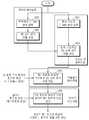
도 8은 3차원적 장기 모델 기반의 동적 장기와 병변 추적 방법의 전체적인 흐름도를 나타낸 것이다. 802단계와 803단계는 기처리된 데이터 베이스화되어질 수 있다. 802단계는 다양한 개인에 대해 각 개인의 다양한 호흡 주기에 대한 CT(computed tomography) 혹은 MR(magnetic resonance)영상을 입력받는다. 803단계는 입력받은 영상을 토대로 3차원 신체 장기 모델을 생성하는데 3차원 ASM(active shape models) 알고리즘을 사용할 수 있음은 상기 설명한 바 있다.Figure 8 shows the overall flow diagram of the dynamic organ and lesion tracking method based on the three-dimensional organ model.
801단계는 환자 개인의 CT(computed tomography) 혹은 MR(magnetic resonance)영상을 입력받는다. 804단계는 입력받은 영상을 기초로 상기 803단계에서 생성된 3차원 신체 장기 모델을 변형시킨다. 상기 개인화된 3차원 신체 장기 모델을 생성하는 과정은 준비과정으로 시술실 밖에서도 행하여 질 수 있다. 805단계는 환자 1 호흡 주기 동안의 초음파 영상(이하, 제 1 초음파 영상이라 한다.)이 입력되고, 상기 제 1 초음파 영상과 상기 개인화된 신체 장기 모델과 정합(match)한다. 정합된 영상을 초음파-모델정합영상이라 하고, 일시적 메모리에 저장될 수도 있고 스토리지와 같은 저장매체에 저장될 수도 있다. 상기 805단계는 시술실 내의 준비과정으로 행하여 질 수 있다. 또한 805단계와 806단계의 환자와 프로브의 위치는 고정되어 있음이 바람직하다. 806단계에서 시술실에서의 실시간 단계로써 실시간으로 환자의 초음파 영상(제 2 초음파 영상)이 입력되면 상기 초음파 영상과 가장 유사한 상기 제 1 초음파 영상이 결정되고 상기 결정된 제 1 초음파 영상에 대응하는 초음파-모델 정합영상을 출력한다.In
한편, 상술한 본 발명의 실시예들은 컴퓨터에서 실행될 수 있는 프로그램으로 작성 가능하고, 컴퓨터로 읽을 수 있는 기록매체를 이용하여 상기 프로그램을 동작시키는 범용 디지털 컴퓨터에서 구현될 수 있다. 또한, 상술한 본 발명의 실시예에서 사용된 데이터의 구조는 컴퓨터로 읽을 수 있는 기록매체에 여러 수단을 통하여 기록될 수 있다. 상기 컴퓨터로 읽을 수 있는 기록매체는 마그네틱 저장매체(예를 들면, 롬, 플로피 디스크, 하드 디스크 등), 광학적 판독 매체(예를 들면, 시디롬, 디브이디 등)와 같은 저장매체를 포함한다.Meanwhile, the above-described embodiments of the present invention can be written as a program that can be executed in a computer, and can be implemented in a general-purpose digital computer that operates the program using a computer-readable recording medium. In addition, the structure of the data used in the above-described embodiment of the present invention can be recorded on the computer-readable recording medium through various means. The computer-readable recording medium includes a storage medium such as a magnetic storage medium (e.g., ROM, floppy disk, hard disk, etc.), optical reading medium (e.g., CD ROM,
이제까지 본 발명에 대하여 그 바람직한 실시예들을 중심으로 살펴보았다. 본 발명이 속하는 기술 분야에서 통상의 지식을 가진 자는 본 발명이 본 발명의 본질적인 특성에서 벗어나지 않는 범위에서 변형된 형태로 구현될 수 있음을 이해할 수 있을 것이다. 그러므로 개시된 실시예들은 한정적인 관점이 아니라 설명적인 관점에서 고려되어야 한다. 본 발명의 범위는 전술한 설명이 아니라 특허청구범위에 나타나 있으며, 그와 동등한 범위 내에 있는 모든 차이점은 본 발명에 포함된 것으로 해석되어야 할 것이다.So far I looked at the center of the preferred embodiment for the present invention. It will be understood by those skilled in the art that various changes in form and details may be made therein without departing from the spirit and scope of the invention as defined by the appended claims. Therefore, the disclosed embodiments should be considered in an illustrative rather than a restrictive sense. The scope of the present invention is defined by the appended claims rather than by the foregoing description, and all differences within the scope of equivalents thereof should be construed as being included in the present invention.
11:프로브10:영상 검출 장치
20:영상 정합 장치30:영상 표시 장치11: probe 10: image detection device
20: video matching device 30: video display device
Claims (21)
Translated fromKorean상기 환자의 신체 활동에 따른 상기 적어도 하나의 장기의 형태적 변화를 나타내는 복수 개의 영상들과 상기 장기의 3차원 모델을 정합함으로써 복수 개의 정합 영상들을 생성하는 단계; 및
상기 환자의 현재 신체 상태에 기초하여 상기 정합 영상들 중 어느 하나를 선택하여 출력하는 단계를 포함하는 장기 영상 생성 방법.Generating a three-dimensional model of the at least one organ based on a medical image representing the at least one organ of the patient;
Generating a plurality of registration images by matching a plurality of images representing a morphological change of the at least one organ according to the physical activity of the patient with a three-dimensional model of the organ; And
Selecting and outputting any one of the registration images based on the current physical condition of the patient.
상기 3차원 모델을 생성하는 단계의 상기 3차원 모델은 환자 의료 영상에 기초하여 환자의 장기 형태를 나타내는 3차원 모델을 생성하는 장기 영상 생성 방법.The method of claim 1,
The three-dimensional model of generating the three-dimensional model is a long-term image generation method for generating a three-dimensional model representing the shape of the patient's organs based on the patient medical image.
상기 정합 영상들을 생성하는 단계는 상기 장기의 형태적 변화를 기초로 상기 3차원 모델을 변형하는 단계; 및
상기 3차원 모델의 좌표축과 상기 복수 개의 영상들의 좌표축을 일치시키는 단계를 포함하는 장기 영상 생성 방법.The method of claim 1,
The generating of the registration images may include modifying the 3D model based on the morphological change of the organ; And
And matching the coordinate axis of the three-dimensional model with the coordinate axis of the plurality of images.
상기 정합 영상들을 생성하는 단계는 상기 복수 개의 영상들의 픽셀/복셀값을 일정 밝기로 중첩하여 상기 정합 영상을 생성하는 장기 영상 생성 방법.The method of claim 3, wherein
The generating of the matched images may include generating the matched image by overlapping pixel / voxel values of the plurality of images with a predetermined brightness.
상기 출력하는 단계는 상기 복수 개의 영상 중 실시간 의료영상의 영상과 가장 유사한 영상에 대응하는 정합 영상을 선택하는 장기 영상 생성 방법.The method of claim 1,
The outputting may include selecting a matching image corresponding to an image most similar to an image of a real-time medical image among the plurality of images.
상기 출력하는 단계는 상기 복수 개의 영상의 횡격막의 위치와 상기 실시간 의료 영상의 횡격막의 위치의 차이를 계산하여, 가장 차이가 작은 영상에 대응하는 정합 영상을 선택하는 장기 영상 생성 방법.The method of claim 5, wherein
The outputting may include calculating a difference between positions of the diaphragms of the plurality of images and positions of the diaphragms of the real-time medical image, and selecting a matched image corresponding to the image having the smallest difference.
상기 3차원 모델을 생성하는 단계는 상기 의료 영상에서 장기의 경계와 내부 구조의 위치 좌표 정보를 추출하는 단계;
특징점(Landmark points)의 좌표를 상기 위치 좌표 정보 내에서 지정하는 단계; 및
통계적인 외관 모델을 생성하는 단계를 포함하는 장기 영상 생성 방법.The method of claim 1,
The generating of the 3D model may include extracting position coordinate information of a boundary of an organ and an internal structure from the medical image;
Designating coordinates of Landmark points in the position coordinate information; And
Long term image generation method comprising the step of generating a statistical appearance model.
상기 3차원 모델을 생성하는 단계는 상기 통계적인 외관 모델을 환자 장기의 형태적 특성을 반영한 모델로 변형하는 단계를 더 포함하는 장기 영상 생성 방법.The method of claim 7, wherein
The generating of the 3D model further includes transforming the statistical appearance model into a model reflecting the morphological characteristics of the patient organ.
상기 3차원 모델을 생성하는 단계는 환자의 의료 영상을 기초로 환자 장기의 형태적 특성을 반영하는 장기 영상 생성 방법.The method of claim 8,
The generating of the three-dimensional model is a long-term image generation method that reflects the morphological characteristics of the patient organs based on the medical image of the patient.
상기 위치 좌표 정보를 추출하는 단계는 상기 의료 영상에서 밝기값의 변화가 최대인 지점을 장기의 경계와 내부 구조의 위치 좌표 정보로 결정하는 장기 영상 생성 방법.The method of claim 7, wherein
The extracting of the position coordinate information may include determining a point at which the change of the brightness value is the largest in the medical image as the position coordinate information of the boundary of the organ and the internal structure.
상기 위치 좌표 정보를 추출하는 단계는 상기 의료 영상에서 DTFT(Discrete Time Fourier Transform)의 주파수의 값이 극대점인 지점을 장기의 경계와 내부 구조의 위치 좌표 정보로 결정하는 장기 영상 생성 방법.11. The method of claim 10,
The extracting of the position coordinate information may include determining the point where the frequency value of the discrete time fourier transform (DTFT) is the maximum point in the medical image as the position coordinate information of the boundary of the organ and the internal structure.
상기 위치 좌표 정보를 추출하는 단계는 상기 의료 영상에서 사용자에 의해 입력받은 좌표를 기초로 장기의 경계와 내부 구조의 위치 좌표 정보로 결정하는 장기 영상 생성 방법.The method of claim 7, wherein
The extracting of the position coordinate information may include determining the position coordinate information of the boundary of the organ and the internal structure based on the coordinates input by the user in the medical image.
상기 복수 개의 영상들은 호흡 주기에서 일정간격으로 형성된 영상인 장기 영상 생성 방법.The method of claim 1,
And the plurality of images are images formed at regular intervals in a breathing cycle.
상기 적어도 하나의 장기를 나타내는 의료 영상은 CT(computed tomography) 방식을 이용하여 촬영한 영상인 장기 영상 생성 방법.The method of claim 1,
The medical image representing the at least one organ is an image taken using a computed tomography (CT) method.
상기 적어도 하나의 장기를 나타내는 의료 영상은 MR(magnetic resonance) 방식을 이용하여 촬영한 영상인 장기 영상 생성 방법.The method of claim 1,
The medical image representing the at least one organ is an image taken by using an MR (magnetic resonance) method.
상기 복수 개의 영상과 상기 환자의 실시간 의료 영상은 초음파 영상인 장기 영상 생성 방법.The method according to claim 1 or 2,
And a plurality of images and real-time medical images of the patient are ultrasound images.
상기 3차원 모델을 생성하는 단계는 데이터 베이스에 저장된 기생성된 3차원 모델을 입력받는 단계로 치환한 장기 영상 생성 방법.The method of claim 1,
The generating of the 3D model may include replacing the generated 3D model stored in a database with a long term image generating method.
상기 형태적 특성은 병변의 형태와 위치를 더 포함하는 장기 영상 생성 방법.10. The method according to claim 8 or 9,
The morphological characteristics of the organ image generation method further comprises the shape and location of the lesion.
환자의 신체 활동에 따른 적어도 하나의 장기의 형태적 변화를 나타내는 복수 개의 영상들과 상기 장기의 3차원 모델을 정합한 영상을 생성하는 영상 정합부; 및
상기 환자의 현재 신체 상태에 기초하여 상기 정합 영상들 중 어느 하나를 선택하는 영상 검색부를 포함하는 장기 영상 생성 장치.An organ model generator configured to generate a 3D model of the at least one organ based on a medical image representing at least one organ of the patient;
An image matching unit generating a plurality of images representing morphological changes of at least one organ according to physical activity of a patient and an image of the three-dimensional model of the organ; And
And an image search unit for selecting one of the registration images based on the current physical condition of the patient.
상기 정합된 영상을 사용자의 입력에 의해 추가적으로 더 조정할 수 있는 추가 조정부를 더 포함하는 장기 영상 생성 장치.The method of claim 19,
And a further adjusting unit configured to further adjust the matched image by a user's input.
Priority Applications (4)
| Application Number | Priority Date | Filing Date | Title |
|---|---|---|---|
| US13/425,597US20120253170A1 (en) | 2011-03-29 | 2012-03-21 | Method and apparatus for generating medical image of body organ by using 3-d model |
| JP2012073631AJP2012205899A (en) | 2011-03-29 | 2012-03-28 | Image generating method and system of body organ using three-dimensional model and computer readable recording medium |
| EP12161756.7AEP2505162B1 (en) | 2011-03-29 | 2012-03-28 | Method and apparatus for generating medical image of body organ by using 3-D model |
| CN201210089147.3ACN102727236B (en) | 2011-03-29 | 2012-03-29 | By the method and apparatus using the medical image of 3D model generation organ |
Applications Claiming Priority (2)
| Application Number | Priority Date | Filing Date | Title |
|---|---|---|---|
| US201161468754P | 2011-03-29 | 2011-03-29 | |
| US61/468,754 | 2011-03-29 |
Publications (1)
| Publication Number | Publication Date |
|---|---|
| KR20120111871Atrue KR20120111871A (en) | 2012-10-11 |
Family
ID=47282459
Family Applications (1)
| Application Number | Title | Priority Date | Filing Date |
|---|---|---|---|
| KR1020110086694AWithdrawnKR20120111871A (en) | 2011-03-29 | 2011-08-29 | Method and apparatus for creating medical image using 3d deformable model |
Country Status (1)
| Country | Link |
|---|---|
| KR (1) | KR20120111871A (en) |
Cited By (23)
| Publication number | Priority date | Publication date | Assignee | Title |
|---|---|---|---|---|
| KR20130026041A (en)* | 2011-09-05 | 2013-03-13 | 삼성전자주식회사 | Method and apparatus for creating medical image using partial medical image |
| KR20140055787A (en)* | 2012-11-01 | 2014-05-09 | 삼성전자주식회사 | Method, apparatus and medical imaging system for segmenting image of object from image of organ |
| KR20140067526A (en)* | 2012-11-26 | 2014-06-05 | 삼성전자주식회사 | Method and apparatus of matching medical images |
| KR20140105101A (en)* | 2013-02-21 | 2014-09-01 | 삼성전자주식회사 | Method and Apparatus for performing registraton of medical images |
| WO2014148806A1 (en)* | 2013-03-18 | 2014-09-25 | 삼성전자주식회사 | Apparatus and method for automatically registering landmarks in three-dimensional medical image |
| WO2014204126A3 (en)* | 2013-06-21 | 2015-04-23 | 한국디지털병원수출사업협동조합 | Apparatus for capturing 3d ultrasound images and method for operating same |
| WO2015068928A1 (en)* | 2013-11-05 | 2015-05-14 | 한국디지털병원수출사업협동조합 | Three-dimensional ultrasonic diagnostic apparatus and method, comprising merging of three-dimensional ultrasonic scanned images |
| KR20150106867A (en) | 2015-09-03 | 2015-09-22 | 삼성전자주식회사 | Method for Providing Medical Image and Apparatus Thereof |
| US9934588B2 (en) | 2013-12-23 | 2018-04-03 | Samsung Electronics Co., Ltd. | Method of and apparatus for providing medical image |
| US10275114B2 (en) | 2016-05-31 | 2019-04-30 | Coreline Soft Co., Ltd. | Medical image display system and method for providing user interface enabling three-dimensional mesh to be edited on three-dimensional volume |
| KR20190078061A (en)* | 2017-12-26 | 2019-07-04 | 아주대학교산학협력단 | Method and apparatus for breast shape deformation |
| KR20190088419A (en)* | 2018-05-23 | 2019-07-26 | (주)휴톰 | Program and method for generating surgical simulation information |
| KR102014359B1 (en)* | 2018-02-20 | 2019-08-26 | (주)휴톰 | Method and apparatus for providing camera location using surgical video |
| WO2019164271A1 (en)* | 2018-02-20 | 2019-08-29 | (주)휴톰 | Virtual body model generation method and device |
| WO2019164275A1 (en)* | 2018-02-20 | 2019-08-29 | (주)휴톰 | Method and device for recognizing position of surgical instrument and camera |
| KR20200056855A (en)* | 2018-11-15 | 2020-05-25 | 서울여자대학교 산학협력단 | Method, apparatus and program for generating a pneumoperitoneum model |
| KR20200122141A (en) | 2019-04-17 | 2020-10-27 | 옵티멈솔루션 주식회사 | Apparatus for medical image segmentation and method for modeling using the same |
| WO2023008818A1 (en)* | 2021-07-29 | 2023-02-02 | (주)휴톰 | Device and method for matching actual surgery image and 3d-based virtual simulation surgery image on basis of poi definition and phase recognition |
| WO2023018138A1 (en)* | 2021-08-10 | 2023-02-16 | (주)휴톰 | Device and method for generating virtual pneumoperitoneum model of patient |
| US11660142B2 (en) | 2017-12-28 | 2023-05-30 | Hutom Co., Ltd. | Method for generating surgical simulation information and program |
| WO2023234626A1 (en)* | 2022-05-30 | 2023-12-07 | (주)휴톰 | Apparatus and method for generating 3d model for organ and blood vessel according to type of surgery |
| KR20240038600A (en) | 2022-09-16 | 2024-03-25 | 주식회사 필드큐어 | Method for creating a patient specific 3D model |
| WO2024117721A1 (en)* | 2022-12-01 | 2024-06-06 | 사회복지법인 삼성생명공익재단 | Method and apparatus for reconstructing three-dimensional liver image |
- 2011
- 2011-08-29KRKR1020110086694Apatent/KR20120111871A/ennot_activeWithdrawn
Cited By (29)
| Publication number | Priority date | Publication date | Assignee | Title |
|---|---|---|---|---|
| KR20130026041A (en)* | 2011-09-05 | 2013-03-13 | 삼성전자주식회사 | Method and apparatus for creating medical image using partial medical image |
| KR20140055787A (en)* | 2012-11-01 | 2014-05-09 | 삼성전자주식회사 | Method, apparatus and medical imaging system for segmenting image of object from image of organ |
| KR20140067526A (en)* | 2012-11-26 | 2014-06-05 | 삼성전자주식회사 | Method and apparatus of matching medical images |
| US10542955B2 (en) | 2012-11-26 | 2020-01-28 | Samsung Electronics Co., Ltd. | Method and apparatus for medical image registration |
| KR20140105101A (en)* | 2013-02-21 | 2014-09-01 | 삼성전자주식회사 | Method and Apparatus for performing registraton of medical images |
| US9799115B2 (en) | 2013-03-18 | 2017-10-24 | Samsung Electronics Co., Ltd. | Apparatus and method for automatically registering landmarks in three-dimensional medical image |
| WO2014148806A1 (en)* | 2013-03-18 | 2014-09-25 | 삼성전자주식회사 | Apparatus and method for automatically registering landmarks in three-dimensional medical image |
| WO2014204126A3 (en)* | 2013-06-21 | 2015-04-23 | 한국디지털병원수출사업협동조합 | Apparatus for capturing 3d ultrasound images and method for operating same |
| WO2015068928A1 (en)* | 2013-11-05 | 2015-05-14 | 한국디지털병원수출사업협동조합 | Three-dimensional ultrasonic diagnostic apparatus and method, comprising merging of three-dimensional ultrasonic scanned images |
| US9934588B2 (en) | 2013-12-23 | 2018-04-03 | Samsung Electronics Co., Ltd. | Method of and apparatus for providing medical image |
| KR20150106867A (en) | 2015-09-03 | 2015-09-22 | 삼성전자주식회사 | Method for Providing Medical Image and Apparatus Thereof |
| US10275114B2 (en) | 2016-05-31 | 2019-04-30 | Coreline Soft Co., Ltd. | Medical image display system and method for providing user interface enabling three-dimensional mesh to be edited on three-dimensional volume |
| KR20190078061A (en)* | 2017-12-26 | 2019-07-04 | 아주대학교산학협력단 | Method and apparatus for breast shape deformation |
| US11660142B2 (en) | 2017-12-28 | 2023-05-30 | Hutom Co., Ltd. | Method for generating surgical simulation information and program |
| KR102014355B1 (en)* | 2018-02-20 | 2019-08-26 | (주)휴톰 | Method and apparatus for calculating location information of surgical device |
| WO2019164271A1 (en)* | 2018-02-20 | 2019-08-29 | (주)휴톰 | Virtual body model generation method and device |
| WO2019164275A1 (en)* | 2018-02-20 | 2019-08-29 | (주)휴톰 | Method and device for recognizing position of surgical instrument and camera |
| KR102014359B1 (en)* | 2018-02-20 | 2019-08-26 | (주)휴톰 | Method and apparatus for providing camera location using surgical video |
| KR20190099999A (en)* | 2018-02-20 | 2019-08-28 | (주)휴톰 | Method, apparatus and program for constructing surgical simulation information |
| KR20190088419A (en)* | 2018-05-23 | 2019-07-26 | (주)휴톰 | Program and method for generating surgical simulation information |
| KR20200056855A (en)* | 2018-11-15 | 2020-05-25 | 서울여자대학교 산학협력단 | Method, apparatus and program for generating a pneumoperitoneum model |
| KR20200122141A (en) | 2019-04-17 | 2020-10-27 | 옵티멈솔루션 주식회사 | Apparatus for medical image segmentation and method for modeling using the same |
| WO2023008818A1 (en)* | 2021-07-29 | 2023-02-02 | (주)휴톰 | Device and method for matching actual surgery image and 3d-based virtual simulation surgery image on basis of poi definition and phase recognition |
| WO2023018138A1 (en)* | 2021-08-10 | 2023-02-16 | (주)휴톰 | Device and method for generating virtual pneumoperitoneum model of patient |
| WO2023234626A1 (en)* | 2022-05-30 | 2023-12-07 | (주)휴톰 | Apparatus and method for generating 3d model for organ and blood vessel according to type of surgery |
| KR20230167194A (en)* | 2022-05-30 | 2023-12-08 | (주)휴톰 | Method, device and program for generating 3d model of organ and blood vessel according to the type of surgery |
| KR20240038600A (en) | 2022-09-16 | 2024-03-25 | 주식회사 필드큐어 | Method for creating a patient specific 3D model |
| WO2024117721A1 (en)* | 2022-12-01 | 2024-06-06 | 사회복지법인 삼성생명공익재단 | Method and apparatus for reconstructing three-dimensional liver image |
| KR20240082092A (en)* | 2022-12-01 | 2024-06-10 | 사회복지법인 삼성생명공익재단 | Method and apparatus for generating 3 dimention liver images |
Similar Documents
| Publication | Publication Date | Title |
|---|---|---|
| KR20120111871A (en) | Method and apparatus for creating medical image using 3d deformable model | |
| KR101982149B1 (en) | Method and apparatus for creating medical image using partial medical image | |
| EP2505162B1 (en) | Method and apparatus for generating medical image of body organ by using 3-D model | |
| KR102001219B1 (en) | Method and Apparatus of matching medical images | |
| CN114732517B (en) | Left Atrial Appendage Closure Guidance in Medical Imaging | |
| KR102094502B1 (en) | Method and Apparatus for performing registraton of medical images | |
| KR102114415B1 (en) | Method and Apparatus for medical image registration | |
| KR102233427B1 (en) | Method and Apparatus for medical image registration | |
| KR20130143434A (en) | Method and apparatus for tracking focus of high-intensity focused ultrasound | |
| CN109152566B (en) | Correcting for probe-induced deformations in ultrasound fusion imaging systems | |
| CN108289651A (en) | System for tracking the ultrasonic probe in body part | |
| KR20090059048A (en) | Anatomical modeling method and system from three-dimensional images and surface mapping | |
| US20140018676A1 (en) | Method of generating temperature map showing temperature change at predetermined part of organ by irradiating ultrasound wave on moving organs, and ultrasound system using the same | |
| KR20140032810A (en) | Method and appartus of maching medical images | |
| KR101993384B1 (en) | Method, Apparatus and system for correcting medical image by patient's pose variation | |
| KR20150145106A (en) | Method and appartus for registering medical images | |
| JP2011200542A (en) | Patient positioning method and patient positioning system | |
| JPWO2020138136A1 (en) | Image processing equipment, image processing methods and programs | |
| KR20160057024A (en) | Markerless 3D Object Tracking Apparatus and Method therefor | |
| KR20140021109A (en) | Method and system to trace trajectory of lesion in a moving organ using ultrasound | |
| EP4062838A1 (en) | Method for use in ultrasound imaging | |
| JP2013505779A (en) | Computer readable medium, system, and method for improving medical image quality using motion information | |
| CN117653163A (en) | Liver image acquisition processing method, system, computer and terminal | |
| Chen | QUiLT (Quantitative Ultrasound in Longitudinal Tissue Tracking): Stitching 2D images into 3D Volumes for Organ Health Monitoring | |
| KR20230163211A (en) | Medical image displaying method and apparatus |
Legal Events
| Date | Code | Title | Description |
|---|---|---|---|
| PA0109 | Patent application | Patent event code:PA01091R01D Comment text:Patent Application Patent event date:20110829 | |
| PG1501 | Laying open of application | ||
| PC1203 | Withdrawal of no request for examination | ||
| WITN | Application deemed withdrawn, e.g. because no request for examination was filed or no examination fee was paid |