KR20120109965A - Method for controlling induction heating cooker - Google Patents
Method for controlling induction heating cookerDownload PDFInfo
- Publication number
- KR20120109965A KR20120109965AKR1020110078105AKR20110078105AKR20120109965AKR 20120109965 AKR20120109965 AKR 20120109965AKR 1020110078105 AKR1020110078105 AKR 1020110078105AKR 20110078105 AKR20110078105 AKR 20110078105AKR 20120109965 AKR20120109965 AKR 20120109965A
- Authority
- KR
- South Korea
- Prior art keywords
- heating coil
- heating
- container
- power level
- pulse width
- Prior art date
- Legal status (The legal status is an assumption and is not a legal conclusion. Google has not performed a legal analysis and makes no representation as to the accuracy of the status listed.)
- Ceased
Links
Images


Classifications
- H—ELECTRICITY
- H05—ELECTRIC TECHNIQUES NOT OTHERWISE PROVIDED FOR
- H05B—ELECTRIC HEATING; ELECTRIC LIGHT SOURCES NOT OTHERWISE PROVIDED FOR; CIRCUIT ARRANGEMENTS FOR ELECTRIC LIGHT SOURCES, IN GENERAL
- H05B6/00—Heating by electric, magnetic or electromagnetic fields
- H05B6/02—Induction heating
- H05B6/06—Control, e.g. of temperature, of power
- H05B6/062—Control, e.g. of temperature, of power for cooking plates or the like
- H05B6/065—Control, e.g. of temperature, of power for cooking plates or the like using coordinated control of multiple induction coils
- H—ELECTRICITY
- H05—ELECTRIC TECHNIQUES NOT OTHERWISE PROVIDED FOR
- H05B—ELECTRIC HEATING; ELECTRIC LIGHT SOURCES NOT OTHERWISE PROVIDED FOR; CIRCUIT ARRANGEMENTS FOR ELECTRIC LIGHT SOURCES, IN GENERAL
- H05B6/00—Heating by electric, magnetic or electromagnetic fields
- H05B6/02—Induction heating
- H05B6/10—Induction heating apparatus, other than furnaces, for specific applications
- H05B6/12—Cooking devices
- H05B6/1209—Cooking devices induction cooking plates or the like and devices to be used in combination with them
- H05B6/1245—Cooking devices induction cooking plates or the like and devices to be used in combination with them with special coil arrangements
- H05B6/1272—Cooking devices induction cooking plates or the like and devices to be used in combination with them with special coil arrangements with more than one coil or coil segment per heating zone
- H—ELECTRICITY
- H05—ELECTRIC TECHNIQUES NOT OTHERWISE PROVIDED FOR
- H05B—ELECTRIC HEATING; ELECTRIC LIGHT SOURCES NOT OTHERWISE PROVIDED FOR; CIRCUIT ARRANGEMENTS FOR ELECTRIC LIGHT SOURCES, IN GENERAL
- H05B2213/00—Aspects relating both to resistive heating and to induction heating, covered by H05B3/00 and H05B6/00
- H05B2213/03—Heating plates made out of a matrix of heating elements that can define heating areas adapted to cookware randomly placed on the heating plate
- Y—GENERAL TAGGING OF NEW TECHNOLOGICAL DEVELOPMENTS; GENERAL TAGGING OF CROSS-SECTIONAL TECHNOLOGIES SPANNING OVER SEVERAL SECTIONS OF THE IPC; TECHNICAL SUBJECTS COVERED BY FORMER USPC CROSS-REFERENCE ART COLLECTIONS [XRACs] AND DIGESTS
- Y02—TECHNOLOGIES OR APPLICATIONS FOR MITIGATION OR ADAPTATION AGAINST CLIMATE CHANGE
- Y02B—CLIMATE CHANGE MITIGATION TECHNOLOGIES RELATED TO BUILDINGS, e.g. HOUSING, HOUSE APPLIANCES OR RELATED END-USER APPLICATIONS
- Y02B40/00—Technologies aiming at improving the efficiency of home appliances, e.g. induction cooking or efficient technologies for refrigerators, freezers or dish washers
Landscapes
- Physics & Mathematics (AREA)
- Electromagnetism (AREA)
- Induction Heating Cooking Devices (AREA)
Abstract
Translated fromKoreanDescription
Translated fromKorean본 발명은 유도가열조리기의 제어방법에 관한 것으로서, 보다 상세하게는 용기가 조리판 위의 어느 위치에 놓여 있어도 용기를 가열할 수 있는 유도가열조리기 의 제어방법에 관한 것이다.
The present invention relates to a method of controlling an induction heating cooker, and more particularly, to a control method of an induction heating cooker capable of heating a container even when the container is placed on a cooking plate.
일반적으로 유도가열조리기는 가열코일에 고주파 전류를 공급하여 강력한 고주파 자계를 발생시키고 이 자계를 통해 가열코일과 자기 결합하고 있는 조리용기(이하 "용기"라 한다.)에 와전류를 발생시킴으로써 와전류에 의한 주울 열로 음식물을 조리할 수 있도록 한 장치이다.Generally, induction heating cooker generates high frequency magnetic field by supplying high frequency current to heating coil and generates eddy current in cooking vessel (hereinafter referred to as “vessel”) which is magnetically coupled with heating coil through this magnetic field. It is a device to cook food with Joule heat.
이러한 유도가열조리기는 외관을 형성하는 본체 내부에 열원을 제공하기 위한 복수의 가열코일이 고정 설치된다. 또한, 본체의 상부에는 용기를 올려놓기 위한 조리판이 마련된다. 이 조리판에는 가열코일에 대응하는 위치에 용기 라인이 새겨져 있고, 이 용기 라인은 사용자가 음식물을 조리하고자 할 때 용기를 올려놓아야 할 위치를 안내하는 역할을 한다.The induction heating cooker is fixedly installed with a plurality of heating coils to provide a heat source inside the body forming the appearance. In addition, the upper portion of the main body is provided with a cooking plate for placing the container. The cooking plate is engraved with a container line at a position corresponding to the heating coil, and the container line serves to guide the position where the container should be placed when the user wants to cook food.
하지만, 이러한 기존의 유도가열조리기를 이용하여 음식물을 조리하면 원활한 조리의 수행을 위해 사용자가 용기 라인에 용기를 정확하게 올려 놓아야 하는 번거로움이 있었다. 즉, 사용자가 용기 라인에서 벗어난 위치에 용기를 올려놓으면 조리가 제대로 이루어지지 않는 문제점이 존재하였다.However, when food is cooked using the conventional induction heating cooker, there is a hassle for a user to accurately place a container on a container line for smooth cooking. That is, when the user puts the container in the position away from the container line there was a problem that cooking is not made properly.
이러한 문제점을 개선하기 위해 최근에는 조리판 전면(全面)에 걸쳐 그 하부에 다수의 가열코일들을 배치하여 사용자가 용기를 조리판 위의 어느 위치에 올려 놓더라도 조리가 원활하게 수행될 수 있도록 하는 신개념의 유도가열조리기가 개발되고 있다.In order to remedy this problem, recently, a plurality of heating coils are disposed on the bottom of the cooking plate so that the cooking can be performed smoothly regardless of where the user places the container on the cooking plate. Induction heating cookers have been developed.
최근 개발되고 있는 유도가열조리기를 이용하여 음식물을 조리할 경우에는 사용자가 조리판 위에 용기를 올려놓은 후 조리 동작을 시작하기 전에 조리판 위의 용기가 놓여있는 위치를 검출하는 동작(용기 위치검출동작)이 선행되어야 한다.When cooking food using an induction heating cooker, which is being developed recently, the user places a container on a cooking plate and detects the position of the container on the cooking plate before starting the cooking operation. ) Must be preceded.
이러한 용기 위치검출동작이 이루어지면 사용자로부터 용기에 대한 파워레벨을 입력받는데, 인접한 코일에 다른 파워레벨이 입력되면 각각의 코일에 인가되는 펄스폭 변조신호의 동작주파수의 차이로 간섭소음이 발생한다.When the vessel position detection operation is performed, the power level for the vessel is input from the user. When a different power level is input to an adjacent coil, interference noise is generated due to a difference in the operating frequency of the pulse width modulation signal applied to each coil.
또한, 인접한 코일에 동일한 파워레벨이 입력되어도 각각의 코일의 점유면적에 따라 상이한 펄스폭 변조신호의 동작주파수로 제어함으로서 간섭소음이 발생할 수 있다. 용기에 의해 점유된 인접한 코일의 면적이 상호 다르면 코일로 흐르는 출력전류가 다르게 감지되고, 각각의 코일의 출력전류가 입력된 파워레벨의 대응하는 목표전류의 범위로 수렴제어하기 위해선 서로 다른 듀티비의 펄스폭 변조신호를 인가해야되기 때문이다.In addition, even when the same power level is input to adjacent coils, interference noise may occur by controlling the operating frequency of a different pulse width modulated signal according to the occupied area of each coil. If the area of adjacent coils occupied by the container is different, the output current flowing to the coils is sensed differently, and the output current of each coil is different from each other in order to control the convergence to the range of the corresponding target current of the input power level. This is because a pulse width modulated signal must be applied.
본 발명의 일 측면은 인접한 복수의 가열코일에 동일한 파워레벨이 입력되면 가열코일의 점유면적에 상관없이 인가된 펄스폭 변조신호의 동작주파수를 동일하게 변경하는 유도가열조리기의 제어방법을 제공하고자 한다.One aspect of the present invention is to provide a control method of an induction heating cooker that changes the operating frequency of an applied pulse width modulated signal equally regardless of the occupied area of the heating coil when the same power level is input to a plurality of adjacent heating coils. .
본 발명의 다른 측면은 인접한 복수의 가열코일에 상이한 복수의 파워레벨이 입력되면 복수의 파워레벨 중 최대 파워레벨에 대응하는 펄스폭 변조신호를 복수의 가열코일에 인가하고 최대 파워레벨이 입력된 가열코일을 제외한 적어도 하나 이상의 가열코일은 시분할 제어되는 유도가열조리기의 제어방법을 제공하고자 한다.According to another aspect of the present invention, when a plurality of different power levels are input to a plurality of adjacent heating coils, a pulse width modulation signal corresponding to the maximum power level among the plurality of power levels is applied to the plurality of heating coils, and the maximum power level is input. At least one heating coil except for the coil is to provide a control method of the induction heating cooker is time-division controlled.
전술한 목적을 달성하기 위한 본 발명의 일 실시예에 따른 유도가열조리기의 제어방법은 조리판, 상기 조리판 상에 놓여진 용기를 가열하는 복수의 가열코일, 상기 가열코일 각각에 고주파 전원을 공급하는 복수의 인버터부 및 상기 인버터부에 의한 고주파 전원에 따라 상기 가열코일 각각에서 흐르는 전류를 감지하는 감지부를 포함하는 유도가열조리기의 제어방법으로서, 상기 가열코일 중 용기가 점유한 가열코일을 검출하고, 사용자로부터 입력된 파워레벨이 상기 검출된 가열코일에 인가되도록 상기 인버터부를 스위칭하고, 상기 용기가 점유한 가열코일이 복수이면 상기 각 가열코일의 감지부에서 감지된 출력전류 중 상기 파워레벨에 상응하는 목표출력전류의 범위에 속하는 출력전류가 존재하는지 결정하고, 상기 목표 출력전류의 범위에 속하는 출력전류가 존재하지 않으면 상기 출력전류 중 적어도 어느 하나가 상기 목표 출력전류의 범위에 도달할 때까지 각 가열코일의 인버터부에 인가되는 펄스폭 변조신호를 조정하되, 상기 펄스폭 변조신호의 듀티비는 상호 동일하게 조정된다.Control method of the induction heating cooker according to an embodiment of the present invention for achieving the above object is a cooking plate, a plurality of heating coils for heating the vessel placed on the cooking plate, supplying a high frequency power to each of the heating coils A control method of an induction heating cooker including a plurality of inverters and a sensing unit for sensing the current flowing in each of the heating coils in accordance with a high frequency power by the inverter unit, detecting the heating coils occupied by the container of the heating coils, Switching the inverter unit so that the power level input from the user is applied to the detected heating coil, and when there are a plurality of heating coils occupied by the container, the power level corresponding to the power level among the output currents sensed by the sensing unit of each heating coil. It is determined whether there is an output current belonging to the range of the target output current, and it belongs to the range of the target output current. If the output current does not exist, the pulse width modulation signal applied to the inverter unit of each heating coil until at least one of the output current reaches the range of the target output current is adjusted, the duty of the pulse width modulation signal The ratios are equally adjusted to each other.
한편, 펄스폭 변조신호의 듀티비는 상기 가열코일의 출력전류 중 가장 큰 출력전류가 상기 목표 출력전류의 범위에 도달할 때까지 변경될 수 있다.On the other hand, the duty ratio of the pulse width modulated signal may be changed until the largest output current of the output current of the heating coil reaches the target output current range.
또한, 조리중인 제1용기와 인접하게 제2용기를 추가적으로 놓을 경우 상기 제2용기가 점유한 가열코일을 검출하고, 상기 제2용기에 대해 상기 사용자 인터페이스부로부터 입력받은 파워레벨을 확인하여 상기 제1용기와 제2용기의 파워레벨이 동일한지 판단하는 것을 더 포함할 수 있다.In addition, when the second container is additionally placed adjacent to the cooking first container, the heating coil occupied by the second container is detected, and the power level received from the user interface unit is checked for the second container. The method may further include determining whether power levels of the first container and the second container are the same.
또한, 제1용기와 제2용기의 파워레벨이 상이하면 상기 가열코일 각각에 동일한 듀티비의 펄스폭 변조신호를 인가하되 상기 가열코일 중 적어도 하나 이상은 시분할 방식으로 상기 펄스폭 변조신호가 인가될 수 있다.In addition, when the power levels of the first vessel and the second vessel are different, a pulse width modulation signal having the same duty ratio is applied to each of the heating coils, but at least one of the heating coils may be applied in a time division manner. Can be.
또한, 제1용기와 제2용기의 파워레벨 중 최대 파워레벨을 확인하고, 상기 최대 파워레벨에 상응하는 듀티비를 가진 펄스폭 변조신호를 상기 가열코일 각각에 인가하고, 상기 최대 파워레벨의 가열코일을 제외한 적어도 하나 이상의 가열코일을 온오프시키고 온구간에만 상기 펄스폭 변조신호를 인가하여 상기 가열코일을 간헐동작시킬 수 있다.In addition, the maximum power level of the power level of the first vessel and the second vessel is checked, and a pulse width modulation signal having a duty ratio corresponding to the maximum power level is applied to each of the heating coils, and the heating of the maximum power level is performed. The heating coil may be intermittently operated by turning off at least one heating coil except for a coil and applying the pulse width modulation signal only to the whole section.
또한, 가열코일을 간헐동작시키는 것은 상기 가열코일의 온구간과 오프구간의 비율을 상기 최대 파워레벨에 대한 해당 가열코일의 파워레벨에 따라 비례하게 설정할 수 있다.In addition, the intermittent operation of the heating coil may set the ratio of the on section and the off section of the heating coil in proportion to the power level of the heating coil relative to the maximum power level.
또한, 가열코일을 간헐동작시키는 것은 상기 간헐동작하는 가열코일이 오프구간에서 온구간으로 전환할 때 상기 최대 파워레벨의 가열코일을 오프시키고 상기 간헐동작의 가열코일과 동시에 온되도록 제어할 수 있다.In addition, the intermittent operation of the heating coil can be controlled to turn off the heating coil of the maximum power level and to be turned on at the same time as the heating coil of the intermittent operation when the intermittent heating coil is switched from the off section to the warm section.
또한, 용기가 점유한 적어도 하나 이상의 가열코일을 검출하는 것은 상기 복수의 가열코일에 상기 고주파 전원을 번갈아 공급하도록 상기 인버터부의 작동을 제어하고, 상기 인버터부가 작동한 결과 상기 감지부를 통해 감지된 전류값이 미리 설정된 전류값 이상이면 상기 용기가 점유한 가열코일임을 판단할 수 있다.In addition, detecting at least one heating coil occupied by the container controls the operation of the inverter unit to alternately supply the high frequency power to the plurality of heating coils, and the current value detected through the detection unit as a result of the operation of the inverter unit. If it is more than this preset electric current value, it can be determined that the said heating coil occupied by the said container.
또한, 제2용기가 점유한 가열코일을 검출하는 것은 상기 조리중인 제1용기가 점유한 가열코일을 제외한 나머지 가열코일에 상기 고주파 전원을 번갈아 공급하도록 상기 인버터부의 작동을 제어하고, 상기 나머지 가열코일 중 고주파 전원이 공급된 결과 출력된 전류값이 상기 미리 설정된 전류값 이상이면 상기 제2용기가 점유한 가열코일임을 판단할 수 있다.In addition, detecting the heating coil occupied by the second vessel controls the operation of the inverter unit to alternately supply the high frequency power to the remaining heating coils other than the heating coil occupied by the cooking first vessel, and the remaining heating coils. When the current value output as a result of supply of the high frequency power is greater than or equal to the preset current value, it may be determined that the heating coil occupied by the second vessel.
또한, 제2용기가 놓인 이후에 상기 제1용기가 점유한 가열코일 중 적어도 어느 하나의 출력전류가 증가하면 상기 출력전류가 증가한 가열코일이 상기 제1용기와 제2용기가 공동점유한 가열코일인 것으로 판단하는 것을 더 포함할 수 있다.In addition, if the output current of at least one of the heating coils occupied by the first vessel increases after the second vessel is placed, the heating coil having the increased output current is a heating coil jointly occupied by the first vessel and the second vessel. It may further comprise determining to be.
전술한 목적을 달성하기 위한 본 발명의 다른 실시예에 따른 유도가열조리기의 제어방법은 조리판, 상기 조리판 상에 놓여진 용기를 가열하는 복수의 가열코일,상기 가열코일 각각에 고주파 전원을 공급하는 복수의 인버터부 및 상기 인버터부에 의한 고주파 전원에 따라 상기 가열코일 각각에서 흐르는 전류를 감지하는 감지부를 포함하는 유도가열조리기의 제어방법으로서, 상기 가열코일 중 복수의 용기가 점유한 복수의 가열코일을 검출하고, 사용자로부터 입력된 상기 검출된 가열코일의 파워레벨이 동일한지 확인하고, 상기 파워레벨이 상호 동일하면 상기 검출된 가열코일의 감지부에서 감지된 출력전류 중 적어도 어느 하나가 상기 파워레벨에 상응하는 목표 출력전류에 도달할 때까지 각 가열코일의 인버터부에 인가되는 펄스폭 변조신호를 조정하되, 상기 펄스폭 변조신호의 듀티비는 상호 동일하게 조정되고, 상기 파워레벨이 상호 상이하면 상기 검출된 가열코일의 인버터부에 동일한 듀티비의 펄스폭 변조신호를 인가하되 상기 가열코일 중 적어도 하나는 간헐적으로 상기 펄스폭 변조신호를 인가한다.Control method of the induction heating cooker according to another embodiment of the present invention for achieving the above object is a cooking plate, a plurality of heating coils for heating the vessel placed on the cooking plate, supplying a high frequency power to each of the heating coils A control method of an induction heating cooker comprising a plurality of inverters and a sensing unit for sensing a current flowing in each of the heating coils in accordance with a high frequency power by the inverter unit, a plurality of heating coils occupied by a plurality of containers of the heating coils Determining whether the power level of the detected heating coil input from the user is the same, and if the power level is the same, at least one of the output current detected by the detection unit of the detected heating coil is the power level Pulse width modulated signal applied to the inverter of each heating coil until the target output current corresponding to The duty ratio of the pulse width modulated signal is adjusted to be equal to each other, and if the power levels are different from each other, the pulse width modulated signal having the same duty ratio is applied to the inverter unit of the detected heating coil, but at least one of the heating coils is applied. Intermittently applies the pulse width modulated signal.
한편, 사용자 인터페이스부는 상기 가열코일 상에 놓여진 용기의 수량과 위치정보를 표시하고, 상기 표시된 용기의 수량이 상기 올려진 용기의 수량과 일치하지 않을 경우 상기 용기의 수량과 크기를 입력받을 수 있다.On the other hand, the user interface unit displays the quantity and location information of the container placed on the heating coil, and if the quantity of the displayed container does not match the quantity of the raised container can receive the quantity and size of the container.
또한, 펄스폭 변조신호의 듀티비는 상기 가열코일의 출력전류 중 가장 큰 출력전류가 상기 목표 출력전류의 범위에 도달할 때까지 변경될 수 있다.In addition, the duty ratio of the pulse width modulation signal may be changed until the largest output current of the output current of the heating coil reaches the target output current range.
또한, 파워레벨이 상이하면 상기 파워레벨 중 최대 파워레벨을 확인하고, 상기 최대 파워레벨에 상응하는 듀티비를 가진 펄스폭 변조신호를 상기 가열코일 각각에 인가하고, 상기 최대 파워레벨이 입력된 용기가 점유하는 가열코일을 제외한 적어도 하나의 가열코일을 주기적으로 온오프시키고 온구간에만 상기 펄스폭 변조신호를 인가하여 상기 가열코일을 간헐동작시킬 수 있다.In addition, if the power level is different, the maximum power level among the power levels is checked, and a pulse width modulated signal having a duty ratio corresponding to the maximum power level is applied to each of the heating coils, and the container having the maximum power level input thereto. The heating coil may be intermittently operated by periodically turning on or off at least one heating coil except for the heating coil occupied by and applying the pulse width modulation signal only to the whole section.
또한, 가열코일을 간헐동작시키는 것은 상기 가열코일의 온구간과 오프구간의 비율을 상기 최대 파워레벨에 대한 해당 가열코일의 파워레벨에 따라 비례하게 설정할 수 있다.In addition, the intermittent operation of the heating coil may set the ratio of the on section and the off section of the heating coil in proportion to the power level of the heating coil relative to the maximum power level.
또한, 가열코일을 간헐동작시키는 것은 상기 간헐동작하는 가열코일이 오프구간에서 온구간으로 전환할 때 상기 최대 파워레벨의 가열코일을 오프시키고 상기 간헐동작의 가열코일과 동시에 온되도록 제어할 수 있다.In addition, the intermittent operation of the heating coil can be controlled to turn off the heating coil of the maximum power level and to be turned on at the same time as the heating coil of the intermittent operation when the intermittent heating coil is switched from the off section to the warm section.
상술한 본 발명에 따른 유도가열조리기의 제어방법에 따르면 인접한 복수의 가열코일에 인가되는 펄스폭 변조신호의 동작주파수를 항상 일치시켜 인버터부의 스위칭 주파수가 상이함으로 인한 간섭소음을 방지할 수 있다.According to the control method of the induction heating cooker according to the present invention described above, the operation frequency of the pulse width modulated signal applied to a plurality of adjacent heating coils is always matched to prevent the interference noise due to the switching frequency of the inverter unit.
또한, 용기가 복수의 인접한 가열코일 사이에 위치하거나 놓여진 용기가 약자성체임으로 인해 각각의 가열코일의 출력 전류가 입력 파워레벨에 대응하는 목표치에 도달하지 못할 경우 간섭소음의 발생없이 출력 전류를 목표범위에 도달하도록 제어할 수 있다. 이로써 사용자의 희망 파워레벨에 보다 근접하게 제어하여 가열효율을 향상시킬 수 있다.
In addition, when the vessel is located between a plurality of adjacent heating coils or the vessel placed is a weak magnetic body, when the output current of each heating coil does not reach the target value corresponding to the input power level, the output current is set without the interference noise. Can be controlled to reach As a result, the heating efficiency can be improved by controlling closer to the user's desired power level.
도 1은 본 발명의 일 실시예에 따른 유도가열조리기의 구성도이다.
도 2는 본 발명의 일 실시예에 따른 유도가열조리기의 제어블록도이다.
도 3은 도 1에 도시된 사용자 인터페이스부의 상세도이다.
도 4는 도 1에 도시된 사용자 인터페이스부의 상세도이다.
도 5는 본 발명의 일 실시예에 따른 유도가열조리기 상에 하나의 용기가 놓여진 모습의 일 예를 도시한 모습이다.
도 6은 본 발명의 제 1 실시예에 따른 유도가열조리기의 제어방법의 순서도이다.
도 7은 본 발명의 일 실시예에 따른 유도가열조리기의 사용자 인터페이스부에 용기 위치 검출동작의 결과를 표시하는 예시를 도시한 도면이다.
도 8은 용기가 점유한 각 가열코일에 인가되는 펄스폭 변조신호의 일 예와 펄스폭 변조신호가 인가된 결과 검출된 출력전류의 일 예를 도시한 도면이다.
도 9는 간섭소음을 방지하면서 목표 출력전류가 출력되도록 제어하기 위해 조정되는 펄스폭 변조신호와 그 때의 출력전류를 도시한 도면이다.
도 10a는 본 발명의 일 실시예에 따른 유도가열조리기 상에 복수의 용기가 놓여진 모습의 일 예를 도시한 모습이다.
도 10b는 본 발명의 일 실시예에 따른 유도가열조리기 상에 복수의 용기가 놓여진 모습의 일 예를 도시한 모습이다.
도 11은 본 발명의 제 2 실시예에 따른 유도가열조리기의 제어방법을 도시한 순서도이다.
도 12는 각 용기가 점유한 가열코일의 동작타이밍도이다.
도 13은 본 발명의 제 3 실시예에 따른 유도가열조리기의 제어방법을 도시한 순서도이다.
도 14a는 본 발명의 일 실시예에 따른 유도가열조리기의 사용자 인터페이스부에 용기 위치 검출동작의 결과를 표시하는 예시를 도시한 도면이다.
도 14b는 본 발명의 일 실시예에 따른 유도가열조리기의 사용자 인터페이스부를 통해 용기의 수량을 입력하는 예시를 도시한 도면이다.
도 14c는 본 발명의 일 실시예에 따른 유도가열조리기의 사용자 인터페이스부를 통해 용기의 크기를 입력하는 예시를 도시한 도면이다.
도 14d는 본 발명의 일 실시예에 따른 유도가열조리기의 사용자 인터페이스부를 통해 용기의 크기를 입력하는 예시를 도시한 도면이다.1 is a block diagram of an induction heating cooker according to an embodiment of the present invention.
2 is a control block diagram of an induction heating cooker according to an embodiment of the present invention.
FIG. 3 is a detailed view of the user interface unit shown in FIG. 1.
4 is a detailed view of the user interface unit illustrated in FIG. 1.
5 is a view showing an example of a state in which one container is placed on the induction heating cooker according to an embodiment of the present invention.
6 is a flowchart of a control method of an induction heating cooker according to a first embodiment of the present invention.
7 is a view showing an example of displaying the result of the container position detection operation of the user interface unit of the induction heating cooker according to an embodiment of the present invention.
FIG. 8 is a diagram showing an example of a pulse width modulated signal applied to each heating coil occupied by the container and an example of an output current detected as a result of the pulse width modulated signal being applied.
9 is a diagram showing a pulse width modulated signal and an output current at that time, which are adjusted to control the target output current to be output while preventing interference noise.
10A illustrates an example of a state in which a plurality of containers are placed on an induction heating cooker according to an embodiment of the present invention.
10B is a view illustrating an example of a state in which a plurality of containers are placed on an induction heating cooker according to an embodiment of the present invention.
11 is a flowchart illustrating a control method of an induction heating cooker according to a second embodiment of the present invention.
12 is an operation timing diagram of a heating coil occupied by each container.
13 is a flowchart illustrating a control method of an induction heating cooker according to a third embodiment of the present invention.
14A is a view showing an example of displaying the result of the container position detection operation in the user interface unit of the induction heating cooker according to an embodiment of the present invention.
14B is a view showing an example of inputting the quantity of the container through the user interface of the induction heating cooker according to an embodiment of the present invention.
14C is a view illustrating an example of inputting a size of a container through a user interface unit of an induction heating cooker according to an embodiment of the present invention.
14D is a view illustrating an example of inputting a size of a container through a user interface unit of an induction heating cooker according to an embodiment of the present invention.
이하 첨부된 도면을 참조하여 본 발명에 따른 유도가열조리기 및 그 제어방법의 실시예를 설명한다.Hereinafter, an embodiment of an induction heating cooker and a control method thereof according to the present invention will be described with reference to the accompanying drawings.
도 1은 본 발명의 일 실시예에 따른 유도가열조리기의 구성도이다.1 is a block diagram of an induction heating cooker according to an embodiment of the present invention.
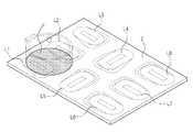
본체(1)의 상부에는 용기(P)를 올려 놓을 수 있도록 마련된 조리판(2)이 설치된다.The
본체(1)의 내부에는 조리판(2) 하부에 설치되어 조리판(2)에 열원을 제공하기 위한 복수의 가열코일(L)이 마련된다. 이 가열코일(L)들은 조리판(2)의 전면(全面)에 걸쳐 그 하부에 조밀한 간격으로 배치된다. 본 발명의 실시예에서는 8개의 가열코일(L)이 배치된 경우를 예로 들어 설명하도록 한다.Inside the main body 1, a plurality of heating coils L are provided below the
또한, 조리판(2)의 하부에는 가열코일(L)들을 구동하기 위한 제어장치(70)가 마련된다. 이 제어장치(70)의 회로 구성에 대해서는 뒤에서 도 2를 참조하여 보다 상세하게 설명하기로 한다.In addition, a
또한, 본체 케이스(1)의 상부에는 가열코일(L)들을 구동시키기 위해 제어장치(70)에 해당 명령을 입력하기 위한 복수의 조작 버튼으로 구성된 조작부 및 유도가열조리기의 작동과 관련된 정보를 표시하는 표시부를 포함하여 이루어지는 사용자 인터페이스부(80)가 마련된다.In addition, the upper portion of the main body case 1 for displaying the information related to the operation of the operation unit and the induction heating cooker consisting of a plurality of operation buttons for inputting a corresponding command to the
따라서 사용자는 용기(P)를 조리판(2)에 올려놓은 후 표시창을 통해 가열코일 중에서 용기의 위치를 확인하고, 조작버튼을 눌러 용기가 놓인 가열코일의 파워레벨을 입력함으로써 가열코일에 입력된 파워레벨에 상응하는 고주파전원을 공급한다.Therefore, the user places the container P on the
도 2는 본 발명의 일 실시예에 따른 유도가열조리기의 제어블록도이다.2 is a control block diagram of an induction heating cooker according to an embodiment of the present invention.
도 2를 참조하면, 본 실시예에 따른 유도가열조리기는 4개의 보조제어부(60A,60B,60C,60D), 하나의 주제어부(70), 사용자 인터페이스부(80)를 포함한다.Referring to FIG. 2, the induction heating cooker according to the present embodiment includes four
본 실시예는 첫번째와 세번째 열은 각각 3개의 가열코일(첫번째열(L1,L2,L3),세번째열(L6,L7,L8))이 배치되고, 두번째 열은 2개의 가열코일(L4,L5)이 배치된 가열코일의 구조를 예를 들어 설명한다. 즉, 첫번째 열부터 세번째 열까지 제1가열코일 내지 제8가열코일로 구성된 8개의 가열코일(L1 내지 L8)이 배치된다.In this embodiment, three heating coils (first row (L1, L2, L3) and third row (L6, L7, L8) are arranged in the first row and the third row, respectively, and two heating coils (L4, L5) are arranged in the second row. The structure of the heating coil in which () is arrange | positioned is demonstrated to an example. That is, eight heating coils L1 to L8 including the first to eighth heating coils are arranged from the first row to the third row.
각각의 보조 제어부(60A,60B,60C,60D)는 복수의 가열코일들 중 하나의 제어단위로 묶인 2개의 가열코일들의 구동을 제어하기 위해 마련되며, 주제어부(70)는 보조제어부(60A,60B,60C,60D)를 제어하기 위해 마련된다.Each
즉, 제 1 보조제어부(60A)는 첫번째 열에서 제1가열코일(L1)과 제2가열코일(L2)의 구동을 제어하고, 제 2 보조제어부(60B)는 제3가열코일(L3)과 제4가열코일(L4)의 구동을 제어한다. 또한, 제3보조제어부(60C)는 제5가열코일(L5)과 제6가열코일(L6)의 구동을 제어하며, 제4보조제어부(60D)는 제7가열코일(L7)과 제8가열코일(L8)의 구동을 제어한다.That is, the first
이러한 8개의 가열코일(L1 내지 L8) 중 하나의 보조제어부(60A,60B,60C,60D)에 연결된 2개의 가열코일을 구동시키기 위한 제어구성들은 모두 동일하므로, 이하에서는 2개의 가열코일을 구동시키기 위한 제어구성에 대해서만 상세하게 설명하고, 그 외의 배열된 가열코일들을 구동시키기 위한 제어구성에 대해서는 그 설명을 생략하기로 한다.Since the control configurations for driving two heating coils connected to one of the
8개의 가열코일(L1 내지 L8) 중에서 제1가열코일(L1)과 제2가열코일(L2)을 구동시키기 위한 제어장치 부분은 정류부(10-1,10-2), 평활부(20-1,20-2), 인버터부(30-1,30-2), 감지부(40-1,40-2), 구동부(50-1,50-2), 제1보조제어부(60A)를 포함한다.Of the eight heating coils (L1 to L8), the control unit for driving the first heating coil (L1) and the second heating coil (L2) is a rectifying unit (10-1, 10-2), smoothing unit 20-1 20-2, inverter units 30-1 and 30-2, sensing units 40-1 and 40-2, driving units 50-1 and 50-2, and first
각각의 가열코일(L1,L2)은 가열코일의 개수에 대응하여 마련된 각각의 인버터부(30-1,30-2)에 의해 독립적으로 구동된다. 즉, 제1가열코일(L1)은 인버터부(30-1)에 의해 구동되고 제 2 가열코일(L2)은 인버터부(30-2)에 의해 구동된다.Each of the heating coils L1 and L2 is independently driven by respective inverter units 30-1 and 30-2 provided corresponding to the number of heating coils. That is, the first heating coil L1 is driven by the inverter unit 30-1 and the second heating coil L2 is driven by the inverter unit 30-2.
정류부(10-1,10-2)는 입력되는 교류전원(AC)을 정류하고, 이 정류된 맥동전압을 출력한다.The rectifiers 10-1 and 10-2 rectify the AC power input AC and output the rectified pulsating voltage.
평활부(20-1,20-2)는 정류부(10-1,10-2)로부터 제공되는 맥동전압을 평활하고, 평활하여 얻은 일정한 직류전압을 출력한다.The smoothing parts 20-1 and 20-2 output a constant DC voltage obtained by smoothing and smoothing the pulsating voltages provided from the rectifying parts 10-1 and 10-2.
인버터부(30-1,30-2)는 평활부(20-1,20-2)로부터 제공되는 직류전압을 구동부의 스위칭 제어신호에 따라 스위칭하여 가열코일(L1,L2)에 공진전압을 제공하는 스위칭 소자(Q)와 각 가열코일(L1,L2)에 병렬연결되어 각 가열코일(L1,L2)과 연속적으로 공진하는 공진 콘덴서(C)를 포함한다.The inverter units 30-1 and 30-2 switch the DC voltages provided from the smoothing units 20-1 and 20-2 according to a switching control signal of the driving unit to provide resonance voltages to the heating coils L1 and L2. And a resonant condenser C connected in parallel with each of the heating elements L1 and L2 and continuously resonating with each of the heating coils L1 and L2.
인버터부(30-1,30-2)는 스위칭 소자(Q)가 도통되면 가열코일(L1,L2)와 공진 콘덴서(C)가 병렬 공진회로를 형성한다. 반대로, 스위칭 소자(Q)가 차단되면 스위칭 소자(Q)가 도통되고 있을 때 공진 콘덴서(C)에 충전되었던 전하들이 방전되면서 가열코일(L1,L2)에 스위칭 소자(Q)가 도통될 때의 고주파 전류와 반대 방향의 전류가 흐르게 된다.In the inverter units 30-1 and 30-2, when the switching element Q is conductive, the heating coils L1 and L2 and the resonant capacitor C form a parallel resonance circuit. On the contrary, when the switching element Q is cut off, the charges charged in the resonant capacitor C are discharged while the switching element Q is conducting, and the switching element Q is conducting to the heating coils L1 and L2. Current flowing in the opposite direction to the high frequency current flows.
감지부(40-1,40-2)는 정류부(10-1,10-2)와 평활부(20-1,20-2) 사이의 라인상에 연결된다. 감지부(40-1,40-2)는 용기가 놓여있는 가열코일을 검출하기 위해 각 가열코일(L1,L2)에 흐르는 전류값을 검출하고, 검출된 각 전류값을 제1보조제어부(60A)에 제공한다.The sensing units 40-1 and 40-2 are connected on a line between the rectifying units 10-1 and 10-2 and the smoothing units 20-1 and 20-2. The detectors 40-1 and 40-2 detect current values flowing through the heating coils L1 and L2 in order to detect the heating coils on which the containers are placed, and detect the detected current values by the first
감지부(40-1,40-2)는 가열코일의 개수에 대응하여 마련되며, 변류기 센서(CT센서, 전류센서)를 포함하여 이루어진다. 한편, 본 실시예에서는 감지부(40-1,40-2)로 변류기 센서를 이용하고, 변류기 센서를 통해 검출된 각 가열코일(L1,L2)에 흐르는 전류값을 이용하여 용기가 놓여있는 가열코일을 검출하는 방식을 예로 들어 설명하였으나, 이러한 변류기 센서 이외에도 전압센서, 압력센서, 전외선 센서 등 다양한 형태의 센서를 이용하여 용기가 놓여있는 가열코일을 검출할 수 있다.The sensing units 40-1 and 40-2 are provided corresponding to the number of heating coils and include current transformer sensors (CT sensors, current sensors). On the other hand, in the present embodiment, using the current transformer sensors as the sensing unit 40-1, 40-2, the heating is placed on the container using the current value flowing through each heating coil (L1, L2) detected through the current transformer sensor Although a coil detection method has been described as an example, in addition to the current transformer sensor, a heating coil in which a container is placed may be detected using various types of sensors such as a voltage sensor, a pressure sensor, and an external ultraviolet sensor.
구동부(50-1,50-2)는 제1보조제어부(60A)의 제어신호에 따라 인버터부(30-1,30-2)의 스위칭 소자(Q)에 구동신호를 출력하여 스위칭 소자(Q)를 온 또는 오프시킨다.The driving units 50-1 and 50-2 output a driving signal to the switching elements Q of the inverter units 30-1 and 30-2 according to the control signal of the first auxiliary control unit 60A. ) On or off.
제1보조제어부(60A)는 주제어부(70)의 제어신호에 따라 각 구동부(50-1,50-1)에 제어신호를 보내어 각 가열코일(L1,L2)의 구동을 제어한다. 또한 제1보조제어부(60A)는 각각의 감지부(40-1,40-2)를 통해 검출된 각 가열코일(L1,L2)에 흐르는 전류값을 입력받아 주 제어부(70)로 전송한다.The first
주 제어부(70)는 유도가열조리기의 전반적인 동작을 제어한다. 주제어부(70)는 2개의 가열코일(L1 내지 L8)의 구동을 제어하는 제1~4 보조제어부(60A,60B,60C,60D)에 통신가능하도록 연결되며, 각 보조 제어부(60A,60B,60C,60D)에 제어신호를 보내어 가열코일(L1 내지 L8)의 구동을 제어한다.The
주제어부(70)는 사용자 인터페이스부(80)를 통해 입력된 용기의 위치검출명령에 따라 각 가열코일(L1 내지 L8)에 고주파 전원을 공급하는 과정을 모든 가열코일(L1 내지 L8)에 번갈아 수행하도록 인버터부(30-1 내지 30-8)의 작동을 제어하면서 감지부(40-1 내지 40-8)를 통해 검출된 각 가열코일(L1 내지 L8)에 흐르는 전류값을 이용하여 가열코일들(L1 내지 L8) 중 용기가 놓여있는 가열코일을 검출한다.The
주제어부(70)는 조리동작을 수행하기 위해 용기가 놓여있는 것으로 판단된 가열코일에 사용자 인터페이스부(80)를 통해 입력된 가열코일의 파워레벨에 상응하는 고주파 전원이 공급되도록 인버터부(30-1 내지 30-8)의 작동을 제어한다.The
특히, 본 실시예에 따른 주제어부(70)는 인접한 코일상에 적어도 하나이상의 용기가 점유하고 있는 경우 각 코일마다 동작주파수가 상이해짐으로 인한 간섭소음을 방지한다.In particular, the
구체적으로, 주제어부(70)는 인접한 복수의 코일에 대한 입력 파워레벨이 동일하면 각 코일 중 어느 하나가 입력 파워레벨에 상응하는 출력전류값의 범위에 도달할 때까지 펄스폭 변조신호의 듀티비를 증가시킨다.Specifically, if the input power level for the plurality of adjacent coils is the same, the
또한, 주제어부(70)는 인접한 복수의 코일에 대한 입력 파워레벨이 상이하면 입력 파워레벨이 최대인 코일을 기준으로 나머지 코일의 펄스폭 변조신호를 제어한다. 구체적으로, 최대의 입력 파워레벨에 상응하는 펄스폭 변조신호를 각 코일에 인가하고, 입력 파워레벨이 최대인 코일을 제외한 나머지 코일은 시분할 제어된다. 이때 시분할 제어는 각 코일의 입력파워레벨과 최대 파워레벨의 비에 따라 설정된다.In addition, the
주제어부(70)는 그 내부에 메모리(70-1)를 포함한다. 메모리(70-1)에는 유도가열조리기의 가열코일(L1 내지 L8) 상에 용기가 놓여 있는지 여부를 판단하기 위한 기준값과, 용기위치검출명령에 따라 검출된 용기의 위치정보와, 각 입력 파워레벨에 상응하는 펄스폭 변조신호 및 목표 출력전류값의 범위정보가 저장된다.The
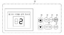
사용자 인터페이스부(80)는 도 3 및 도 4와 같이 전원을 온 또는 오프하기 위한 ON/OFF버튼(81), 용기위치검출동작의 명령을 입력하기 위한 자동(AUTO)버튼(82), 가열코일의 파워레벨을 조절하기 위한 버튼(83), 조리동작의 시작 또는 정지를 입력하기 위한 시작/정지(START/PAUSE)버튼(84) 등 다수의 버튼을 포함한다.3 and 4, the
또한, 사용자 인터페이스부(80)는 자동(AUTO)버튼(82)을 입력한 결과 검출된 용기의 위치정보(85)를 표시하고, 상기 용기의 위치상에 사용자로부터 파워레벨 조절 버튼(83)을 통해 입력받은 파워레벨(86) 등을 표시한다.In addition, the
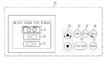
또한, 사용자 인터페이스부(80)는 도 4와 같이 옵션버튼(87)과 선택(ENTER,88)버튼을 더 포함하여 용기의 수량과 그 크기를 사용자로부터 입력받을 수 있다.In addition, the
다수의 용기를 인접하게 조리판 상에 동시에 올려놓고 용기위치 검출동작의 명령에 따라 용기를 검출하면 인접한 다수의 코일에 하나의 용기로 점유하고 있음으로 사용자 인터페이스부(80) 상에 표시된다.When a plurality of containers are simultaneously placed on a cooking plate and the containers are detected according to a command of a container position detecting operation, they are displayed on the
본 실시예에 따른 사용자 인터페이스부(80)는 사용자로부터 용기의 수량을 입력받고, 각 용기의 위치 및 점유도 등을 입력받아 보다 정확하게 용기의 위치를 표시할 수 있다. 이로써 용기를 하나씩 올려놓고 그 위치를 인식한 후 다른 용기를 올려놓을 수 밖에 없었던 사용자 인터페이스부(80)와 달리 다수의 용기를 동시에 올려놓아도 정확한 용기의 위치인식이 가능할 수 있다.The
본 실시예에서는 상술한 바와 같은 가열코일(L1 내지 L8)의 구조에서 2개의 가열코일마다 보조제어부(60A,60B,60C,60D)가 배치되고, 이 보조제어부(60A,60B,60C,60D)들을 제어하기 위한 하나의 주제어부(70)가 마련된는 구성을 예를 들어 설명하였으나, 이와는 다른 형태로 가열코일과 보조제어부의 배치를 구성하거나, 보조제어부를 채용하기 않고 하나의 제어부만으로 모든 코일을 제어하도록 구성할 수 있다.In the present embodiment, in the structure of the heating coils L1 to L8 as described above, the
이하에서는 가열코일간의 동작주파수의 차이로 인한 간섭소음을 방지하는 유도가열조리기의 제어방법에 대해 설명한다.Hereinafter, a control method of an induction heating cooker for preventing interference noise due to a difference in operating frequency of a heating coil will be described.
도 5는 본 발명의 일 실시예에 따른 유도가열조리기에서 하나의 용기가 제1가열코일(L1)과 제2가열코일(L2) 상에 위치한 경우를 나타낸 것이다. 도 5에 따른 용기는 제1가열코일(L1) 상에 더 많은 점유도를 차지한 상태로 위치한 것을 알 수 있다.5 illustrates a case where one container is placed on the first heating coil L1 and the second heating coil L2 in the induction heating cooker according to the embodiment of the present invention. It can be seen that the container according to FIG. 5 is located in a state that occupies more occupancy on the first heating coil L1.
도 6은 본 발명의 제 1 실시예에 따른 유도가열조리기의 제어방법의 순서도이다.6 is a flowchart of a control method of an induction heating cooker according to a first embodiment of the present invention.
본 실시예에 따른 유도가열조리기의 제어방법은 도 5와 같이 조리판에 하나의 용기로 복수의 가열코일을 점유할 경우의 간섭소음을 방지하기 위한 제어방법이다.The control method of the induction heating cooker according to the present embodiment is a control method for preventing the interference noise when occupying a plurality of heating coils in one container on the cooking plate as shown in FIG.
도 6을 참조하면 사용자는 음식물을 조리하기 위해 조리판 위에 용기를 올려놓은 후 ON/OFF 버튼을 조작하여 유도가열조리기의 전원을 온시킨다(110). 이후 사용자는 조리판 위의 용기가 놓여있는 위치(용기가 놓여있는 가열코일의 위치)를 검출하기 위해 자동(AUTO)버튼을 조작하여 용기의 위치검출명령을 입력한다(120).Referring to FIG. 6, a user places a container on a cooking plate to cook food and then turns on the power of the induction heating cooker by operating an ON / OFF button (110). Then, the user inputs a position detection command of the container by operating an AUTO button to detect the position of the container on the cooking plate (the position of the heating coil on which the container is placed) (120).
이렇게 사용자의 자동버튼 조작에 의해 용기의 위치검출명령신호가 입력(120)되면 주제어부는 유도가열조리기 내의 각각의 가열코일에 흐르는 전류값을 검출하기 위해 각 보조제어부(제 1 내지 제4 보조제어부)에 용기위치검출명령을 전송한다.When the position detection command signal of the container is
이렇게 용기위치검출명령을 전송받는 각 보조제어부는 각 구동부에 제어신호를 보내어 일정시간동안(약 0.5~2초) 각 가열코일에 고주파 전원이 공급되도록 한다(130).In this way, each auxiliary control unit receiving the container position detection command transmits a control signal to each drive unit so that high frequency power is supplied to each heating coil for a predetermined time (about 0.5 to 2 seconds) (130).
고주파 전원이 공급되면 가열코일별로 마련된 각 감지부는 각 가열코일에 흐르는 전류값을 검출하여 각 보조제어부로 전송한다(130).When the high frequency power is supplied, each sensing unit provided for each heating coil detects a current value flowing through each heating coil and transmits it to each auxiliary control unit (130).
보조제어부는 이러한 전류값을 주제어부로 전송하고, 이후 주제어부는 상기 검출된 전류값이 미리 설정된 값 이상인가 여부를 판단한다(130). 여기서, 미리 설정된 값이란 가열코일 상에 용기가 놓여있는지 여부를 판단하기 위한 기준값으로서, 주제어부의 메모리상에 미리 저장되어 있다.The auxiliary control unit transmits the current value to the main control unit, and then the main control unit determines whether the detected current value is greater than or equal to a preset value (130). Here, the preset value is a reference value for determining whether the container is placed on the heating coil, and is stored in advance in the memory of the main control part.
판단결과, 검출된 각 가열코일에 흐르는 전류값이 미리 설정된 값 이상이면 주제어부는 해당 가열코일 위에 용기가 놓여있음을 메모리에 저장시키고, 미리 설정된 값 미만이면 용기가 놓여있지 않음을 메모리에 저장시킨다(140).As a result of the determination, if the current value flowing through each of the detected heating coils is greater than or equal to the preset value, the main control unit stores in the memory that the container is placed on the heating coil, and if it is less than the preset value, stores the container in the memory. 140).
도 5와 같이 용기가 제1가열코일(L1) 및 제2가열코일(L2) 상에 올려져 있으므로, 메모리에는 제1가열코일(L1) 및 제2가열코일(L2)에 용기가 놓여있음이 저장되어 있고 나머지 가열코일(L3 내지 L8)에는 용기가 놓여있지 않음의 정보가 저장된다.Since the container is mounted on the first heating coil L1 and the second heating coil L2 as shown in FIG. 5, the container is placed on the first heating coil L1 and the second heating coil L2 in the memory. It is stored and the remaining heating coils (L3 to L8) is stored information that no vessel is placed.
이렇게 모든 가열코일에 대한 용기위치검출동작이 완료되면, 메모리에 저장된 용기의 위치정보가 사용자 인터페이스부에 도 7과 같이 표시된다(140). 도 7의 사용자 인터페이스부(80)는 가열코일(L1~L8)의 배치 구조가 새겨진 표시면 상에 용기가 놓여있는 가열코일(L1,L2)에 대응하는 위치를 점등방식으로 표시한다.When the vessel position detection operation for all the heating coils is completed in this way, the position information of the vessel stored in the memory is displayed as shown in FIG. The
사용자는 도 7에서와 같이 용기의 위치를 확인하고 파워레벨 조작버튼(83)을 조작하여 사용자가 원하는 파워레벨(조리정도)를 입력한다(150). 이렇게 입력된 파워레벨은 가열코일의 위치정보가 표시된 하단에 막대 그래프 형상(86)으로 표시할 수 있다. 이때 막대그래프(860)의 높이는 파워레벨에 비례하여 높아진다.The user checks the position of the container as shown in FIG. 7 and operates the power
파워레벨이 입력되면 사용자 인터페이스부는 시작/정지(84) 버튼을 통해 조리의 시작명령을 입력받고, 이를 주제어부로 전송한다. 주제어부는 파워레벨에 대응하는 펄스폭 변조신호를 메모리에서 검색후 해당 펄스폭 변조신호를 용기가 놓여있는 가열코일을 제어하는 보조제어부 상으로 전송한다(160).When the power level is input, the user interface unit receives a start command of cooking through the start /
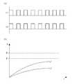
예컨대(도 5참조), 주제어부는 도 8의 (a)에 도시된 바와 같은 펄스폭 변조신호를 제1가열코일(L1)과 제2가열코일(L2)을 제어하는 제1보조제어부로 전송하고, 제1보조제어부는 제1가열코일(L1)과 제2가열코일(L2) 각각의 인버터부가 상기 펄스폭 변조신호(도 8의 (a))에 따라 스위칭될 수 있도록 제어한다.For example (see FIG. 5), the main control unit transmits a pulse width modulated signal as shown in FIG. 8A to the first auxiliary control unit for controlling the first heating coil L1 and the second heating coil L2. The first auxiliary control unit controls the inverter units of the first heating coil L1 and the second heating coil L2 to be switched according to the pulse width modulation signal (FIG. 8A).
용기가 올려진 각 가열코일이 펄스폭 변조신호에 따라 구동하면, 각 가열코일에서 출력된 전류가 감지부를 통해 감지된다(160).When each heating coil on which the container is loaded is driven according to the pulse width modulation signal, the current output from each heating coil is sensed through the sensing unit (160).
감지된 출력전류는 도 8의 (b)와 같이 용기가 각 가열코일 상을 점유한 면적에 따라 상이하다. 도 8의 (b)를 참조하면, 용기가 제1가열코일(L1)과 제2가열코일(L2) 상을 점유하고 있고, 그 점유면적은 제1가열코일(L1)이 더 크므로(도 5참조) 제1가열코일(L1)에서 출력되는 전류가 제2가열코일(L2)의 출력전류보다 크게 감지됨을 알 수 있다.The sensed output current is different depending on the area occupied by each vessel coil as shown in FIG. Referring to FIG. 8B, the container occupies the first heating coil L1 and the second heating coil L2, and the occupied area of the container is larger than that of the first heating coil L1 (FIG. 5) It can be seen that the current output from the first heating coil L1 is larger than the output current of the second heating coil L2.
즉, 동일한 펄스폭 변조신호를 각 가열코일에 인가하더라도, 용기가 가열코일을 점유한 면적에 따라 출력전류가 상이하고, 이에 따라 적게 점유한 가열코일은 사용자가 원하는 파워레벨로 용기를 가열할 수 없게 된다.That is, even if the same pulse width modulated signal is applied to each heating coil, the output current differs according to the area occupied by the container in the heating coil, and thus the less occupied heating coil can heat the container at a power level desired by the user. There will be no.
따라서, 각각의 가열코일이 입력 파워레벨에 상응하는 목표 전류범위의 전류를 출력할 수 있도록 제어하는 과정이 필요하다.Therefore, a process of controlling each heating coil to output a current of a target current range corresponding to the input power level is necessary.
먼저 각 가열코일에 인가되는 펄스폭 변조신호의 듀티비를 증가시킨다. 펄스폭 변조신호의 듀티비를 증가시키면 하이레벨의 구간의 시간이 로우레벨의 시간보다 상대적으로 길게 변화되고, 이렇게 듀티비가 증가된 펄스폭 변조신호가 인가되면 각 가열코일의 출력전류가 증가하게 된다.First, the duty ratio of the pulse width modulated signal applied to each heating coil is increased. When the duty ratio of the pulse width modulated signal is increased, the time of the high level section is changed relatively longer than the time of the low level. When the pulse width modulated signal with the increased duty ratio is applied, the output current of each heating coil is increased. .
하지만, 출력전류가 상이한 각각의 가열코일이 목표 전류범위의 전류에 도달하도록 듀티비를 증가시키려면, 인접한 가열코일 각각에 상호 상이한 펄스폭 변조신호가 인가되게 된다. 즉, 인접한 가열코일 각각에 동작주파수가 상이한 펄스폭 변조신호가 인가되고 이로 인해 동작주파수의 차이로 인한 간섭소음이 발생하게 된다.However, to increase the duty ratio so that each heating coil having a different output current reaches a current in the target current range, different pulse width modulation signals are applied to each of the adjacent heating coils. That is, a pulse width modulation signal having a different operating frequency is applied to each of the adjacent heating coils, thereby causing interference noise due to a difference in operating frequency.
따라서, 본 실시예는 상술한 바와 같은 간섭소음의 문제를 해결하기 위해 인접한 가열코일 중 적어도 어느 하나의 출력전류를 기준으로 펄스폭 변조신호를 인가한다(170,180,190).Accordingly, the present embodiment applies the pulse width modulated signal based on the output current of at least one of the adjacent heating coils to solve the interference noise problem described above (170, 180, 190).
구체적으로, 본 실시예는 출력된 가열코일 각각의 출력전류 중 적어도 어느 하나가 입력 파워레벨에 상응하는 목표 출력전류의 범위에 속하는지 확인한다(170). 도 8의 (b)를 참조하면, 제1가열코일 및 제2가열코일은 용기가 부분점유하고 있어 각 가열코일의 전류값은 목표 출력전류의 범위에 속하지 못함을 확인할 수 있다.In detail, the present embodiment verifies whether at least one of the output currents of each of the output heating coils falls within a range of the target output current corresponding to the input power level (170). Referring to (b) of FIG. 8, it can be seen that the first heating coil and the second heating coil are partially occupied by the container, so that the current value of each heating coil does not belong to the target output current range.
이렇게 각 가열코일의 출력전류 모두가 목표 출력전류의 범위에 속하지 않음이 확인되면(각 가열코일에 대해 용기가 부분점유함), 주제어부는 인접한 가열코일 중 적어도 어느 하나의 출력전류를 기준으로 제어한다. 즉, 적어도 어느 하나의 출력전류가 목표 전류범위에 도달할 때까지 나머지 가열코일에 인가되는 펄스폭 변조신호의 듀티비가 동일하게 증가된다(180,190). 이때, 펄스폭 변조신호의 듀티비는 미리 설정된 시간간격마다 일정하게 증가시키며 조정될 수 있는데, 본 실시예는 1초의 간격마다 상기 듀티비를 증가시키며 조정한다.When it is confirmed that the output current of each heating coil does not belong to the target output current range (the container is partially occupied for each heating coil), the main controller controls the output current based on at least one of the adjacent heating coils. . That is, the duty ratio of the pulse width modulated signal applied to the remaining heating coils is equally increased until at least one output current reaches the target current range (180 and 190). In this case, the duty ratio of the pulse width modulated signal may be adjusted to increase constantly at a predetermined time interval. In this embodiment, the duty ratio is increased and adjusted at intervals of 1 second.
도 9는 간섭소음을 방지하면서 목표 출력전류가 출력되도록 제어하기 위해 조정되는 펄스폭 변조신호와 그 때의 출력전류를 도시한 도면이다.9 is a diagram showing a pulse width modulated signal and an output current at that time, which are adjusted to control the target output current to be output while preventing interference noise.
도 9를 참조하면, 주제어부는 제1가열코일(L1) 및 제2가열코일(L2) 중 점유비가 높은 제1가열코일(L1)의 출력전류값이 목표 전류범위(I1~I2)에 도달할 때까지 제1가열코일(L1)과 제2가열코일(L2)에 인가하는 펄스폭 변조신호의 듀티비를 미리 설정된 시간간격마다 일정하게 증가시킨다.Referring to FIG. 9, the main control unit may output an output current value of the first heating coil L1 having a high occupancy ratio among the first heating coil L1 and the second heating coil L2 to reach the target current range I1 to I2. Until the duty ratio of the pulse width modulated signal applied to the first heating coil (L1) and the second heating coil (L2) until a constant time interval until.
특히, 본 실시예의 주제어부는 도 9의 (a)와 같이 펄스폭 변조신호의 듀티비를 증가시키되, 각 가열코일에 동일한 펄스폭 변조신호가 인가되도록 제어한다.In particular, the main control unit of the present embodiment increases the duty ratio of the pulse width modulated signal as shown in FIG. 9A, and controls the same pulse width modulated signal to be applied to each heating coil.
이렇게 듀티비가 증가된 펄스폭 변조신호가 각 가열코일(L1,L2)에 인가되면 도 9의 (b)와 같이 제1가열코일(L1)의 출력전류는 제어시점서부터(t1) 전류변화량 (△I)만큼 증가하여 목표 전류범위(I1~I2)에 도달하고, 제2가열코일(L2)의 출력전류는 제어시점서(t1)부터 제1가열코일(L1)의 전류변화량(△I)보다 적은 전류변화량(△I')만큼 상승함을 알 수 있다.When the pulse width modulated signal with increased duty ratio is applied to each heating coil L1 and L2, the output current of the first heating coil L1 is changed from the control point of time (t1) as shown in FIG. 9 (b). It increases by I) and reaches the target current range I1 to I2, and the output current of the second heating coil L2 is smaller than the current change amount ΔI of the first heating coil L1 from the control time point t1. It can be seen that the current rises by a small amount of current change ΔI '.
즉, 본 실시예는 듀티비 증가제어의 기준이 된 가열코일을 제외하고 나머지 가열코일의 출력전류가 목표 전류범위에 정확하게 도달하지 못하더라도 동작주파수가 동일한 펄스폭 변조신호를 인접 가열코일에 인가하여 간섭소음을 방지한다.That is, the present embodiment applies a pulse width modulated signal having the same operating frequency to the adjacent heating coils even if the output current of the remaining heating coils does not reach the target current range except the heating coil which is the reference for the duty ratio increase control. Prevent interference noise
한편, 본 실시예는 점유비가 높은 가열코일을 기준으로 펄스폭 변조신호를 인가하였으나 그 밖의 가열코일을 기준으로 펄스폭 변조신호를 제어하여도 간섭소음을 방지하기 위해 모든 가열코일에 동일하게 듀티비가 증가된 펄스폭 변조신호를 인가하는 제어라면 본 발명의 범주에 포함된다.In the present embodiment, the pulse width modulated signal is applied based on a heating coil having a high occupancy ratio. However, even if the pulse width modulated signal is controlled based on other heating coils, the duty ratio is equally applied to all heating coils to prevent interference noise. Any control that applies an increased pulse width modulated signal is included in the scope of the present invention.
지금까지 하나의 용기가 다수의 가열코일을 점유할 경우의 제어방법에 대해 설명하였다.The control method in the case where one container occupies many heating coils was demonstrated so far.
이하, 도 10a처럼 복수의 용기(P1,P2)가 가열코일을 공동으로 점유(제2가열코일)하며 인접하게 조리판 상에 놓여있을 때와 도 10b처럼 복수의 용기(P1,P2)가 가열코일을 공동점유하지 않고 인접하게 배치된 경우의 제어방법에 대해 설명한다.Hereinafter, as shown in FIG. 10A, when the plurality of containers P1 and P2 jointly occupy the heating coil (second heating coil) and are placed adjacent to the cooking plate and as shown in FIG. 10B, the plurality of containers P1 and P2 are heated. The control method in the case where the coils are arranged adjacent without having the common occupancy will be described.
한편, 도 10a 및 도 10b는 두개의 용기가 놓여있을 경우만 도시하였으나 다수개의 용기가 인접하게 놓여있을 경우에도 본 발명의 범주에 포함됨은 물론이다.On the other hand, Figures 10a and 10b is shown only when two containers are placed, even if a plurality of containers are placed adjacent to the scope of the present invention, of course.
도 11은 본 발명의 제 2 실시예에 따른 유도가열조리기의 제어방법을 도시한 순서도이다.11 is a flowchart illustrating a control method of an induction heating cooker according to a second embodiment of the present invention.
먼저, 제 2 실시예에 따른 유도가열조리기는 도 3과 같은 사용자 인터페이스부(80)를 구비하여 용기를 하나씩 올려 점유된 가열코일의 위치를 감지하고 상기 용기의 파워레벨을 입력받는 방식으로 구동됨을 가정한다.First, the induction heating cooker according to the second embodiment is provided with a
즉, 용기(이하, 제1용기(P1))가 가열되는 중에 다른 용기(이하, 제2용기(P2))를 제1용기(P1)와 인접하게 놓고 가열할 경우의 제어방법을 도 9를 통해 설명한다.That is, a control method when heating another vessel (hereinafter referred to as a second vessel P2) while adjoining the first vessel P1 while the vessel (hereinafter, the first vessel P1) is heated is shown in FIG. Explain through.
사용자는 제 1 용기(P1)를 가열하다가 제2용기(P2)를 제1용기(P1)에 인접한 곳에 올려놓은 후 제2용기(P2)의 위치를 검출하도록 자동버튼을 조작한다(210,220). 용기 위치검출명령이 입력되면, 주제어부는 제1용기(P1)가 점유하고 있는 가열코일(L1,L2,도 10a 및 도 10b참조)을 제외한 나머지 가열코일(L3~L8)에 고주파 전원을 일정시간동안 인가되도록 제어하고, 각 가열코일의 출력전류를 통해 제2용기(P2)의 위치를 검출하고 이를 사용자 인터페이스부에 표시한다(220,230).The user heats the first container P1 and places the second container P2 adjacent to the first container P1 and then operates the automatic button to detect the position of the second container P2 (210, 220). When the vessel position detection command is input, the main control unit supplies the high frequency power to the remaining heating coils L3 to L8 for a predetermined time except for the heating coils L1 and L2 occupied by the first container P1. It is controlled to be applied for a while, the position of the second container (P2) is detected through the output current of each heating coil and displayed on the user interface unit (220, 230).
또한, 주제어부는 제1용기(P1)가 점유하는 가열코일의 출력전류의 변화여부를 기초로 제1용기(P1)와 제2용기(P2) 사이에 공동점유하고 있는 가열코일이 존재하는지 여부를 판단할 수 있다.In addition, the main control unit determines whether there is a heating coil jointly occupied between the first vessel P1 and the second vessel P2 based on whether the output current of the heating coil occupied by the first vessel P1 changes. You can judge.
구체적으로, 제2용기(P2)가 올려지면 공동점유된 가열코일의 점유면적이 상승하여 출력전류도 상승하는 원리를 이용하여 주제어부는 제1용기(P1)의 가열코일의 출력전류의 상승을 확인하고, 출력전류가 상승된 가열코일이 제2용기(P2)와 공동점유한 가열코일임을 판단한다.Specifically, when the second container P2 is raised, the main control part confirms the increase in the output current of the heating coil of the first container P1 by using the principle that the occupied area of the jointly occupied heating coil increases and the output current also increases. Then, it is determined that the heating coil in which the output current is increased is the heating coil which is commonly occupied with the second container P2.
즉, 도 10a처럼 제1용기(P1)와 제2용기(P2) 사이에 공동점유하는 가열코일(L2)이 존재하는 경우에도 정확한 용기의 위치가 사용자 인터페이스부에 표시될 수 있는 것이다.That is, even when there is a heating coil L2 shared between the first container P1 and the second container P2 as shown in FIG. 10A, the correct position of the container may be displayed on the user interface unit.
제2용기(P2)의 위치가 검색되면(220,230), 사용자로부터 +/-버튼을 통해 제2용기(P2)의 파워레벨을 입력받는다(240).If the location of the second container (P2) is found (220,230), the user receives the power level of the second container (P2) via the + /-button (240).
이때 입력받은 제2용기(P2)의 파워레벨이 제1용기(P1)의 파워레벨과 동일하면(250), 제1용기(P1) 및 제2용기(P2)가 점유하는 가열코일에 대해 도 6과 같은 제어과정으로 간섭소음을 방지하면서 출력전류를 목표 전류범위에 가깝게 도달하도록 제어할 수 있다(261~265).At this time, if the power level of the second container (P2) received is the same as the power level of the first container (P1) (250), the heating coil occupied by the first container (P1) and the second container (P2). The control process as shown in FIG. 6 may control the output current to reach the target current range while preventing interference noise (261 to 265).
즉, 복수의 용기가 점유하는 가열코일의 출력전류 중 어느 하나가 목표 전류범위에 도달하게 하는 펄스폭 변조신호를 각 가열코일에 동일하게 인가하는 것이다(261~265).That is, a pulse width modulation signal for causing any one of the output currents of the heating coils occupied by the plurality of containers to reach the target current range is equally applied to each heating coil (261 to 265).
한편, 제2용기의 파워레벨이 제1용기의 파워레벨과 상이하면(250), 제1용기(P1)의 파워레벨과 제2용기(P2)의 파워레벨 중에서 최대 파워레벨을 기준으로 제어한다(271~273).On the other hand, if the power level of the second container is different from the power level of the first container (250), the control is based on the maximum power level of the power level of the first container (P1) and the power level of the second container (P2). (271-273).
복수의 용기에 대해 입력된 파워레벨이 서로 상이하면 입력 파워레벨 중 최대 입력 파워레벨에 상응하는 듀티비를 가진 펄스폭 변조신호를 각 가열코일에 인가하고, 최대 파워레벨의 용기가 점유하는 가열코일을 제외한 나머지 가열코일은 간헐적으로 펄스폭 변조신호를 인가한다.(271~273)If the input power levels for the plurality of containers are different from each other, a pulse width modulated signal having a duty ratio corresponding to the maximum input power level among the input power levels is applied to each heating coil, and the heating coil occupied by the container having the maximum power level is applied. The remaining heating coils except for apply the pulse width modulated signal intermittently. (271 ~ 273)
따라서, 용기가 점유하는 모든 가열코일에 동일한 펄스폭 변조신호를 인가하여 동작주파수가 다른 펄스폭 변조신호를 인접한 가열코일에 인가함으로써 발생하는 간섭소음의 문제를 해결한다.Therefore, the same pulse width modulated signal is applied to all heating coils occupied by the container, thereby solving the problem of interference noise generated by applying a pulse width modulated signal having a different operating frequency to adjacent heating coils.
구체적으로, 최대 파워레벨의 용기가 점유하는 가열코일은 펄스폭 변조신호를 지속적으로 인가하고, 나머지 가열코일은 최대 파워레벨을 고려하여 온 구간과 오프구간이 주기적으로 반복시키고, 온구간에만 상기 펄스폭 변조신호를 인가하는 방식으로 제어된다.Specifically, the heating coil occupied by the container with the maximum power level continuously applies a pulse width modulated signal, and the remaining heating coil periodically repeats the on and off sections in consideration of the maximum power level. It is controlled by applying a width modulated signal.
즉, 나머지 가열코일에 대해 입력된 파워레벨과 최대 파워레벨의 비에 비례하여 조절된 나머지 가열코일의 온구간에 맞춰 가열코일이 간헐동작하는 것이다.That is, the heating coil intermittently operates in accordance with the warming interval of the remaining heating coil adjusted in proportion to the ratio of the input power level and the maximum power level with respect to the remaining heating coil.
예컨대, 제1용기의 입력 파워레벨이 '6'이고 제2용기의 입력 파워레벨이 '3'이면 주제어부는 최대 파워레벨이 '6'임을 확인하고(271), 최대 파워레벨에 대응하는 펄스폭 변조신호를 제1용기(P1) 및 제2용기(P2)가 점유하는 가열코일에 동일하게 인가한다(272).For example, if the input power level of the first vessel is '6' and the input power level of the second vessel is '3', the main controller determines that the maximum power level is '6' (271), and the pulse width corresponding to the maximum power level. The modulated signal is equally applied to the heating coil occupied by the first vessel P1 and the second vessel P2 (272).
또한, 주제어부는 제1용기(P1)가 점유하는 가열코일에는 지속적으로 펄스폭 변조신호를 인가하면서 제2용기(P2)가 점유하는 가열코일은 간헐 동작시킨다. 제1용기(P1)와 제2용기(P2)가 점유한 가열코일의 동작 타이밍도는 도 12와 같다.In addition, while the main controller continuously applies a pulse width modulation signal to the heating coil occupied by the first vessel P1, the heating coil occupied by the second vessel P2 is intermittently operated. 12 is an operation timing diagram of the heating coil occupied by the first vessel P1 and the second vessel P2.
도 12를 참조하면, 제1용기(P1)가 점유한 가열코일의 인버터부는 지속적으로 펄스폭 변조신호에 맞춰 스위칭하지만 제2용기(P2)가 점유한 가열코일의 인버터부는 간헐적으로 동작한다. 제2용기(P2)가 점유한 가열코일의 인버터부는 최대 파워레벨(6)에 대한 제2용기(P2)의 입력 파워레벨(3)에 비에 따라 간헐동작을 하는데, 제2용기(P2)의 입력 파워레벨(3)은 최대 파워레벨(6)의 반이므로 제2용기(P2) 점유 가열코일의 인버터부의 동작시간(ON구간,T1)과 미동작시간(OFF구간,T2)의 비율은 동일하다. 즉, 온구간(T1)과 오프구간(T2)이 동일한 간격으로 반복되는 것이다.Referring to FIG. 12, the inverter unit of the heating coil occupied by the first vessel P1 continuously switches according to the pulse width modulation signal, but the inverter unit of the heating coil occupied by the second vessel P2 operates intermittently. The inverter unit of the heating coil occupied by the second vessel P2 intermittently operates in accordance with the ratio of the input power level 3 of the second vessel P2 to the maximum power level 6. Since the input power level (3) is half of the maximum power level (6), the ratio of the operating time (ON section, T1) and non-operating time (OFF section, T2) of the inverter section of the heating coil occupied by the second vessel (P2) same. That is, the on section T1 and the off section T2 are repeated at the same interval.
한편, 최대 파워레벨의 가열코일(P1점유 가열코일)을 제외한 나머지 가열코일(P2점유 가열코일)의 간헐동작으로 인해 소음이 발생할 수 있다. 도 12에서와 같이 가열코일이 오프되었다가 온되려면 소정의 라이징타임(rising time,t1)이 경과된 후에 온상태가 된다. 이로 인해 간헐동작의 가열코일이 오프되었다가 온되는 시점마다 동작 주파수가 차이로 인한 간섭소음이 발생하게 된다.On the other hand, noise may occur due to the intermittent operation of the remaining heating coil (P2 occupied heating coil) except for the heating coil (P1 occupied heating coil) of the maximum power level. As shown in FIG. 12, when the heating coil is turned off and on, the heating coil is turned on after a predetermined rising time t1 has elapsed. As a result, an interference noise occurs due to a difference in operating frequency every time the heating coil of the intermittent operation is turned off and on.
따라서, 본 실시예의 주제어부는 간헐동작의 가열코일의 온구간에 맞춰 다른 가열코일도 오프하였다가 동시에 온시킨다. 즉, 제2용기(P2) 점유 가열코일이 오프되고 다시 온되는 시점마다 제1 용기(P1)가 점유한 가열코일도 오프하였다가 동시에 온시켜 각 가열코일의 동작주파수를 맞춰주는 것이다.Therefore, the main control part of this embodiment also turns off other heating coils and turns them on at the same time according to the warming period of the heating coil of an intermittent operation. That is, whenever the heating coil occupied by the second container P2 is turned off and on again, the heating coil occupied by the first container P1 is also turned off and turned on at the same time to adjust the operating frequency of each heating coil.
한편, 본 실시예는 두 개의 용기가 놓여질 경우 파워레벨의 동일여부에 따른 소음방지 제어방법에 대해 설명하였으나 다수의 용기가 근접하게 놓여질 경우에도 동일한 제어방법이 적용됨은 물론이다.On the other hand, the present embodiment has been described with respect to the noise prevention control method according to whether or not the power level is the same when two containers are placed, the same control method is applied even when a plurality of containers are placed in close proximity.
또한, 다수의 용기가 근접하게 놓여있는 상태에서 적어도 어느 하나의 용기의 조리가 완료되어 그 구동의 종료버튼이 입력되었을 경우에도 동일한 제어방법이 적용된다.In addition, the same control method is applied even when cooking of at least one container is completed while a plurality of containers are placed in close proximity and an end button of driving thereof is input.
구체적으로, 각 용기가 서로 다른 파워레벨로 동작하고 있고, 조리가 완료된 용기가 최대 파워레벨로 동작하였을 경우에는 차순위의 파워레벨을 기준으로 제어된다. 즉, 차순위의 파워레벨에 상응하는 펄스폭 변조신호가 모든 가열코일에 인가되고, 파워레벨이 낮은 가열코일에 대해 각 가열코일의 파워레벨과 상기 차순위 파워레벨의 비에 비례하여 간헐동작하도록 제어되는 것이다.Specifically, when each container is operating at a different power level, and when the cooking vessel is operated at the maximum power level, it is controlled based on the next power level. That is, a pulse width modulation signal corresponding to the next power level is applied to all heating coils, and is controlled to intermittently operate in proportion to the ratio of the power level of each heating coil to the next power level for the heating coil having a low power level. will be.
또한, 각 용기가 동일한 파워레벨로 동작하고 있고, 적어도 어느 하나의 용기의 조리가 완료되면(종료버튼 입력후), 주제어부는 나머지 가열코일에서 출력된 전류의 변화여부를 기초로 제어수행 여부를 결정한다. 적어도 어느 하나의 가열코일에 대해 공동점유하고 있던 용기의 조리가 완료되면 그로 인해 공동점유된 가열코일의 출력전류가 변화하기 때문이다. 따라서, 변화된 출력전류를 기초로 적어도 어느 하나의 가열코일의 출력전류가 목표 전류범위에 도달하도록 조절된 펄스폭 변조신호를 각 가열코일에 동일하게 인가한다.In addition, when each vessel is operating at the same power level and at least one vessel has been cooked (after the end button is input), the main controller determines whether to perform control based on the change of the current output from the remaining heating coils. do. This is because when the cooking of the vessel that has been co-occupied with at least one heating coil is completed, the output current of the co-occupied heating coil changes. Therefore, based on the changed output current, the pulse width modulated signal adjusted to the output current of at least one heating coil to reach the target current range is equally applied to each heating coil.
도 13은 본 발명의 제 3 실시예에 따른 유도가열조리기의 제어방법을 도시한 순서도이다.13 is a flowchart illustrating a control method of an induction heating cooker according to a third embodiment of the present invention.
먼저, 제 3 실시예에 따른 유도가열조리기는 도 4와 같은 사용자 인터페이스부(80)를 구비하여 용기를 하나씩 복수개를 올린 경우뿐만 아니라 한번에 복수의 용기를 올린 경우에도 각 용기의 위치파악이 정확하게 이루어질 수 있다.First, the induction heating cooker according to the third embodiment is provided with the
제1용기가 가열되는 중에 다른 용기를 제1용기와 인접하게 놓고 가열하는 경우의 제어방법은 도 11에서와 동일한 바 본 실시예는 제1용기(P1)와 제2용기(P2)를 동시에 올려놓고 제어하는 방법에 대해서만 설명한다.While the first container is heated while the other container is placed adjacent to the first container and heated, the control method is the same as in FIG. 11. In this embodiment, the first container P1 and the second container P2 are simultaneously raised. Only how to put and control.
도 13을 참조하면, 사용자는 제1용기(P1)와 제2용기(P2)를 도 10a 및 도 10b와 같이 인접하게 동시에 올려놓고 용기의 위치를 검출하는 자동버튼을 조작한다(310).Referring to FIG. 13, the user places the first container P1 and the second container P2 at the same time as shown in FIGS. 10A and 10B and operates an automatic button for detecting the position of the container (310).
이렇게 용기 위치검출명령이 입력되면, 각 가열코일에 대한 고주파 전원의 인가 및 검출된 전류의 미리 설정된 값과의 비교를 기초로 용기가 점유된 가열코일을 검출하고 이를 사용자 인터페이스부에 표시한다(310,320).When the vessel position detection command is input in this way, the heating coil occupied by the vessel is detected based on the application of a high frequency power to each heating coil and a comparison with a preset value of the detected current and displayed on the user interface unit (310, 320). ).
제1용기(P1)와 제2용기(P2)에 의해 점유된 가열코일은 제1가열코일(L1) 내지 제3가열코일(L3)이므로 사용자 인터페이스부(80)는 제1가열코일(L1) 내지 제3가열코일(L3)의 위치에 하나의 용기로 점유됨을 도 14a와 같이 표시(85)하게 된다.Since the heating coils occupied by the first container P1 and the second container P2 are the first heating coil L1 to the third heating coil L3, the
사용자는 두개의 용기로 점유됨이 사용자 인터페이스부(80) 상에 표시(85)되도록 도 14a 및 도 14b와 같이 옵션버튼(87)을 입력하고, 파워레벨 조절버튼(83)을 통해 용기의 수량을 입력한다(320).The user inputs the
즉, 사용자 인터페이스부의 조작버튼을 통해 용기의 수량을 입력할 수 있고, 용기의 수량이 입력되면 용기에 크기에 따른 각 가열코일 상의 점유도를 선택할 수 있다.That is, the quantity of the container may be input through an operation button of the user interface unit, and when the quantity of the container is input, the occupancy of each heating coil according to the size may be selected.
구체적으로, 도 14c와 같이 용기의 다양한 점유도를 선택할 수 있는데 비슷한 크기의 용기가 올려져있는 경우(A)와 어느 한쪽의 용기가 더 큰 경우(B,C) 등 다양한 경우에 대해 선택이 가능하고, 그 결과 도 14d와 같이 각 용기의 위치가 정확하게 표시된다.Specifically, as shown in FIG. 14C, various occupancy degrees of the container may be selected, and the case may be selected for various cases such as a case having a container of a similar size (A) and a case where one of the containers is larger (B, C). As a result, the position of each container is accurately displayed as shown in FIG. 14D.
이렇게 제1용기(P1)와 제2용기(P2)의 위치가 사용자 인터페이스부를 통해 확인되면(310,320), 각 용기의 작동 파워레벨을 입력받는다(330).When the position of the first container (P1) and the second container (P2) is confirmed through the user interface unit (310, 320), and receives the operating power level of each container (330).
이렇게 각 용기의 위치가 확인되고 파워레벨이 입력되면(330), 주제어부는 각 용기의 파워레벨이 동일한지 여부를 판단한다(340).When the location of each container is confirmed and the power level is input (330), the main controller determines whether the power level of each container is the same (340).
판단결과, 각 용기의 파워레벨이 동일하면(340) 도 6을 통해 설명한 바와 같이 복수의 용기가 점유하는 가열코일의 출력전류를 기초로 듀티비가 증가된 동일한 펄스폭 변조신호를 각 가열코일에 인가한다(351~355).As a result, when the power level of each container is the same (340), as described with reference to FIG. 6, the same pulse width modulated signal with increased duty ratio is applied to each heating coil based on the output current of the heating coil occupied by the plurality of containers. (351-355).
또한, 각 용기의 파워레벨이 상이하면(340) 도 11을 통해 설명한 바와 같이 최대 파워레벨에 대응하는 듀티비를 가진 펄스폭 변조신호를 각 가열코일에 인가하고(361,362), 최대 파워레벨의 가열코일은 지속적으로 펄스폭 변조신호를 인가하되, 나머지 가열코일은 각 가열코일의 파워레벨에 따라 간헐적으로 펄스폭 변조신호를 인가시킨다(363).In addition, if the power level of each container is different (340), as described with reference to FIG. 11, a pulse width modulated signal having a duty ratio corresponding to the maximum power level is applied to each heating coil (361, 362), and heating of the maximum power level The coil continuously applies the pulse width modulated signal, but the remaining heating coils intermittently apply the pulse width modulated signal according to the power level of each heating coil (363).
즉, 간헐적으로 동작하는 가열코일은 최대 파워레벨에 대한 입력 파워레벨의 비에 비례하여 일정비율로 온오프 제어되는 것이다.That is, the intermittent heating coil is controlled on and off at a constant rate in proportion to the ratio of the input power level to the maximum power level.
또한, 최대 파워레벨의 가열코일도 간헐적으로 동작하는 가열코일의 온타임 직전에 오프되고 같이 온되어 라이징 타임으로 인한 간섭소음이 발생하는 것을 방지할 수 있다.In addition, the heating coil of the maximum power level is also turned off immediately before the on-time of the heating coil that operates intermittently and turned on together to prevent the occurrence of interference noise due to the rising time.
한편, 본 실시예는 두 개의 용기가 놓여질 경우 파워레벨의 동일여부에 따른 소음방지 제어방법에 대해 설명하였으나 다수의 용기가 근접하게 놓여질 경우에도 동일한 제어방법이 적용됨은 물론이다.On the other hand, the present embodiment has been described with respect to the noise prevention control method according to whether or not the power level is the same when two containers are placed, the same control method is applied even when a plurality of containers are placed in close proximity.
또한, 다수의 용기가 근접하게 놓여있는 상태에서 적어도 어느 하나의 용기의 조리가 완료되어 그 구동의 종료버튼이 입력되었을 경우에도 동일한 제어방법이 적용된다.In addition, the same control method is applied even when cooking of at least one container is completed while a plurality of containers are placed in close proximity and an end button of driving thereof is input.
구체적으로, 각 용기가 서로 다른 파워레벨로 동작하고 있고, 조리가 완료된 용기가 최대 파워레벨로 동작하였을 경우에는 차순위의 파워레벨을 기준으로 제어된다.Specifically, when each container is operating at a different power level, and when the cooking vessel is operated at the maximum power level, it is controlled based on the next power level.
또한, 각 용기가 동일한 파워레벨로 동작하고 있고, 적어도 어느 하나의 용기의 조리가 완료되면(종료버튼 입력후), 주제어부는 나머지 가열코일에서 출력된 전류의 변화여부를 기초로 제어수행 여부를 결정한다.In addition, when each vessel is operating at the same power level and at least one vessel has been cooked (after the end button is input), the main controller determines whether to perform control based on the change of the current output from the remaining heating coils. do.
상술한 본 발명에 따른 유도가열조리기의 제어방법에 따르면 인접한 복수의 가열코일에 인가되는 펄스폭 변조신호의 동작주파수를 항상 일치시켜 인버터부의 스위칭 주파수가 상이함으로 인한 간섭소음을 방지할 수 있다.According to the control method of the induction heating cooker according to the present invention described above, the operation frequency of the pulse width modulated signal applied to a plurality of adjacent heating coils is always matched to prevent the interference noise due to the switching frequency of the inverter unit.
또한, 용기가 복수의 인접한 가열코일 사이에 위치하거나 놓여진 용기가 약자성체임으로 인해 각각의 가열코일의 출력 전류가 입력 파워레벨에 대응하는 목표치에 도달하지 못할 경우 간섭소음의 발생없이 출력 전류를 목표범위에 도달하도록 제어할 수 있다. 이로써 사용자의 희망 파워레벨에 보다 근접하게 제어하여 가열효율을 향상시킬 수 있다.In addition, when the vessel is located between a plurality of adjacent heating coils or the vessel placed is a weak magnetic body, when the output current of each heating coil does not reach the target value corresponding to the input power level, the output current is set without the interference noise. Can be controlled to reach As a result, the heating efficiency can be improved by controlling closer to the user's desired power level.
10-1~10-8: 정류부
20-1~20-8: 평활부
30-1~30-8: 인버터부
40-1~40-8: 감지부
50-1~50-8: 구동부
60A~60D: 제1~4 보조제어부
70: 주제어부
70-1: 메모리
80: 사용자 인터페이스부10-1 to 10-8: rectifier
20-1 ~ 20-8: Smooth part
30-1 ~ 30-8: Inverter
40-1 to 40-8: detector
50-1 to 50-8: drive section
60A ~ 60D: 1st-4th Auxiliary Control Unit
70: subject fisherman
70-1: Memory
80: user interface unit
Claims (16)
Translated fromKorean상기 가열코일 중 용기가 점유한 가열코일을 검출하고;
사용자로부터 입력된 파워레벨이 상기 검출된 가열코일에 인가되도록 상기 인버터부를 스위칭하고;
상기 용기가 점유한 가열코일이 복수이면 상기 각 가열코일의 감지부에서 감지된 출력전류 중 상기 파워레벨에 상응하는 목표출력전류의 범위에 속하는 출력전류가 존재하는지 결정하고;
상기 목표 출력전류의 범위에 속하는 출력전류가 존재하지 않으면 상기 출력전류 중 적어도 어느 하나가 상기 목표 출력전류의 범위에 도달할 때까지 각 가열코일의 인버터부에 인가되는 펄스폭 변조신호를 조정하되, 상기 펄스폭 변조신호의 듀티비는 상호 동일하게 조정되는 유도가열조리기의 제어방법.Cooking plate; A plurality of heating coils for heating the container placed on the cooking plate; A plurality of inverter units supplying high frequency power to each of the heating coils; In the control method of the induction heating cooker comprising a; sensing unit for sensing the current flowing in each of the heating coils in accordance with the high-frequency power by the inverter unit,
Detecting a heating coil occupied by the container among the heating coils;
Switching the inverter unit such that a power level input from a user is applied to the detected heating coil;
If there are a plurality of heating coils occupied by the container, determining whether there is an output current within a range of a target output current corresponding to the power level among the output currents sensed by the sensing unit of each heating coil;
If there is no output current within the target output current range, the pulse width modulation signal applied to the inverter unit of each heating coil is adjusted until at least one of the output current reaches the target output current range, And a duty ratio of the pulse width modulated signal is adjusted to be the same.
상기 펄스폭 변조신호의 듀티비는
상기 가열코일의 출력전류 중 가장 큰 출력전류가 상기 목표 출력전류의 범위에 도달할 때까지 변경되는 유도가열조리기의 제어방법.The method of claim 1,
The duty ratio of the pulse width modulated signal is
Control method of the induction heating cooker is changed until the largest output current of the output current of the heating coil reaches the target output current range.
조리중인 제1용기와 인접하게 제2용기를 추가적으로 놓을 경우 상기 제2용기가 점유한 가열코일을 검출하고;
상기 제2용기에 대해 상기 사용자 인터페이스부로부터 입력받은 파워레벨을 확인하여 상기 제1용기와 제2용기의 파워레벨이 동일한지 판단하는 것을 더 포함하는 유도가열조리기의 제어방법.The method of claim 1,
Detecting a heating coil occupied by the second container when the second container is additionally placed adjacent to the cooking first container;
The control method of the induction heating cooker further comprises determining whether the power level of the first vessel and the second vessel is the same by checking the power level received from the user interface unit for the second vessel.
상기 제1용기와 제2용기의 파워레벨이 상이하면
상기 가열코일 각각에 동일한 듀티비의 펄스폭 변조신호를 인가하되 상기 가열코일 중 적어도 하나는 간헐적으로 상기 펄스폭 변조신호가 인가되는 유도가열조리기의 제어방법.The method of claim 3,
If the power level of the first container and the second container is different
And applying a pulse width modulated signal having the same duty ratio to each of the heating coils, wherein at least one of the heating coils is intermittently applied to the pulse width modulated signal.
상기 제1용기와 제2용기의 파워레벨 중 최대 파워레벨을 확인하고;
상기 최대 파워레벨에 상응하는 듀티비를 가진 펄스폭 변조신호를 상기 가열코일 각각에 인가하고;
상기 최대 파워레벨의 가열코일을 제외한 적어도 하나의 가열코일을 온오프시키고 온구간에만 상기 펄스폭 변조신호를 인가하여 상기 가열코일을 간헐동작시키는 유도가열조리기의 제어방법.The method of claim 4, wherein
Confirming a maximum power level among power levels of the first vessel and the second vessel;
Applying a pulse width modulated signal having a duty ratio corresponding to the maximum power level to each of the heating coils;
And controlling at least one heating coil excluding the heating coil of the maximum power level and intermittently operating the heating coil by applying the pulse width modulation signal only to an entire section.
상기 가열코일을 간헐동작시키는 것은
상기 가열코일의 온구간과 오프구간의 비율을 상기 최대 파워레벨에 대한 해당 가열코일의 파워레벨에 따라 비례하게 설정하는 유도가열조리기의 제어방법.The method of claim 5,
Intermittently operating the heating coil
And controlling the ratio between the on and off sections of the heating coil in proportion to the power level of the heating coil relative to the maximum power level.
상기 가열코일을 간헐동작시키는 것은
상기 간헐동작하는 가열코일이 오프구간에서 온구간으로 전환할 때 상기 최대 파워레벨의 가열코일을 오프시키고 상기 간헐동작의 가열코일과 동시에 온되도록 제어하는 유도가열조리기의 제어방법.The method according to claim 6,
Intermittently operating the heating coil
And controlling the heating coil of the maximum power level to be turned on at the same time as the heating coil of the intermittent operation when the heating coil of the intermittent operation is switched from an off section to an on section.
상기 용기가 점유한 적어도 하나 이상의 가열코일을 검출하는 것은
상기 복수의 가열코일에 상기 고주파 전원을 번갈아 공급하도록 상기 인버터부의 작동을 제어하고;
상기 인버터부가 작동한 결과 상기 감지부를 통해 감지된 전류값이 미리 설정된 전류값 이상이면 상기 용기가 점유한 가열코일임을 판단하는 유도가열조리기의 제어방법.The method of claim 3,
Detecting at least one heating coil occupied by the vessel
Controlling the operation of the inverter unit to alternately supply the high frequency power to the plurality of heating coils;
The control method of the induction heating cooker to determine that the heating coil occupied by the container when the current value detected by the detection unit is greater than a preset current value as a result of the operation of the inverter unit.
상기 제2용기가 점유한 가열코일을 검출하는 것은
상기 조리중인 제1용기가 점유한 가열코일을 제외한 나머지 가열코일에 상기 고주파 전원을 번갈아 공급하도록 상기 인버터부의 작동을 제어하고;
상기 나머지 가열코일 중 고주파 전원이 공급된 결과 출력된 전류값이 상기 미리 설정된 전류값 이상이면 상기 제2용기가 점유한 가열코일임을 판단하는 유도가열조리기의 제어방법.9. The method of claim 8,
Detecting the heating coil occupied by the second container
Controlling the operation of the inverter unit to alternately supply the high frequency power to the remaining heating coils other than the heating coil occupied by the cooking first container;
The control method of the induction heating cooker to determine that the heating coil occupied by the second vessel when the current value output as a result of the high-frequency power supplied from the remaining heating coil is more than the predetermined current value.
상기 제2용기가 놓인 이후에 상기 제1용기가 점유한 가열코일 중 적어도 어느 하나의 출력전류가 증가하면 상기 출력전류가 증가한 가열코일이 상기 제1용기와 제2용기가 공동점유한 가열코일인 것으로 판단하는 것을 더 포함하는 유도가열조리기의 제어방법.10. The method of claim 9,
If the output current of at least one of the heating coils occupied by the first vessel increases after the second vessel is placed, the heating coil with increased output current is a heating coil jointly occupied by the first vessel and the second vessel. Control method of the induction heating cooker further comprising determining.
상기 가열코일 중 복수의 용기가 점유한 복수의 가열코일을 검출하고;
사용자로부터 입력된 상기 검출된 가열코일의 파워레벨이 동일한지 확인하고;
상기 파워레벨이 상호 동일하면 상기 검출된 가열코일의 감지부에서 감지된 출력전류 중 적어도 어느 하나가 상기 파워레벨에 상응하는 목표 출력전류에 도달할 때까지 각 가열코일의 인버터부에 인가되는 펄스폭 변조신호를 조정하되, 상기 펄스폭 변조신호의 듀티비는 상호 동일하게 조정되고;
상기 파워레벨이 상호 상이하면 상기 검출된 가열코일의 인버터부에 동일한 듀티비의 펄스폭 변조신호를 인가하되 상기 가열코일 중 적어도 하나는 간헐적으로 상기 펄스폭 변조신호를 인가하는 유도가열조리기의 제어방법.Cooking plate; A plurality of heating coils for heating the container placed on the cooking plate; A plurality of inverter units supplying high frequency power to each of the heating coils; In the control method of the induction heating cooker comprising a; sensing unit for sensing the current flowing in each of the heating coils in accordance with the high-frequency power by the inverter unit,
Detecting a plurality of heating coils occupied by a plurality of containers of the heating coils;
Confirming that power levels of the detected heating coils input from the user are the same;
If the power levels are the same, the pulse width applied to the inverter unit of each heating coil until at least one of the output currents detected by the detection unit of the detected heating coil reaches a target output current corresponding to the power level. Adjust a modulated signal, wherein the duty ratios of the pulse width modulated signals are equally adjusted;
The control method of the induction heating cooker to apply a pulse width modulation signal of the same duty ratio to the inverter unit of the detected heating coil if the power level is different from each other, but at least one of the heating coils intermittently applying the pulse width modulation signal. .
상기 가열코일 상에 놓여진 용기의 수량과 위치정보를 표시하고, 상기 표시된 용기의 수량이 상기 올려진 용기의 수량과 일치하지 않을 경우 상기 용기의 수량과 크기를 입력받는 사용자 인터페이스부를 더 포함하는 유도가열조리기의 제어방법.The method of claim 11,
Induction heating further includes a user interface that displays the quantity and location information of the container placed on the heating coil and receives the quantity and size of the container if the quantity of the displayed container does not match the quantity of the loaded container. How to control your cooker.
상기 펄스폭 변조신호의 듀티비는
상기 가열코일의 출력전류 중 가장 큰 출력전류가 상기 목표 출력전류의 범위에 도달할 때까지 변경되는 유도가열조리기의 제어방법.The method of claim 12,
The duty ratio of the pulse width modulated signal is
Control method of the induction heating cooker is changed until the largest output current of the output current of the heating coil reaches the target output current range.
상기 파워레벨이 상이하면 상기 파워레벨 중 최대 파워레벨을 확인하고;
상기 최대 파워레벨에 상응하는 듀티비를 가진 펄스폭 변조신호를 상기 가열코일 각각에 인가하고;
상기 최대 파워레벨이 입력된 용기가 점유하는 가열코일을 제외한 적어도 하나의 가열코일을 주기적으로 온오프시키고 온구간에만 상기 펄스폭 변조신호를 인가하여 상기 가열코일을 간헐동작시키는 유도가열조리기의 제어방법.The method of claim 11,
Checking the maximum power level among the power levels if the power levels are different;
Applying a pulse width modulated signal having a duty ratio corresponding to the maximum power level to each of the heating coils;
A control method of an induction heating cooker for intermittently operating the heating coil by periodically turning on or off at least one heating coil except for the heating coil occupied by the container into which the maximum power level is input, and applying the pulse width modulation signal only to the whole section. .
상기 가열코일을 간헐동작시키는 것은
상기 가열코일의 온구간과 오프구간의 비율을 상기 최대 파워레벨에 대한 해당 가열코일의 파워레벨에 따라 비례하게 설정하는 유도가열조리기의 제어방법.15. The method of claim 14,
Intermittently operating the heating coil
And controlling the ratio between the on and off sections of the heating coil in proportion to the power level of the heating coil relative to the maximum power level.
상기 가열코일을 간헐동작시키는 것은
상기 간헐동작하는 가열코일이 오프구간에서 온구간으로 전환할 때 상기 최대 파워레벨의 가열코일을 오프시키고 상기 간헐동작의 가열코일과 동시에 온되도록 제어하는 유도가열조리기의 제어방법.16. The method of claim 15,
Intermittently operating the heating coil
And controlling the heating coil of the maximum power level to be turned on at the same time as the heating coil of the intermittent operation when the heating coil of the intermittent operation is switched from an off section to an on section.
Priority Applications (5)
| Application Number | Priority Date | Filing Date | Title |
|---|---|---|---|
| EP12160239.5AEP2506668B1 (en) | 2011-03-28 | 2012-03-20 | Control method of induction heating cooker |
| EP17187410.0AEP3270661A1 (en) | 2011-03-28 | 2012-03-20 | Control method of induction heating cooker |
| US13/427,291US20120248098A1 (en) | 2011-03-28 | 2012-03-22 | Control method of induction heating cooker |
| PCT/KR2012/002140WO2012134119A2 (en) | 2011-03-28 | 2012-03-23 | Control method of induction heating cooker |
| CN2012100855871ACN102711297A (en) | 2011-03-28 | 2012-03-28 | Control method of induction heating cooker |
Applications Claiming Priority (2)
| Application Number | Priority Date | Filing Date | Title |
|---|---|---|---|
| KR1020110027407 | 2011-03-28 | ||
| KR20110027407 | 2011-03-28 |
Publications (1)
| Publication Number | Publication Date |
|---|---|
| KR20120109965Atrue KR20120109965A (en) | 2012-10-09 |
Family
ID=47281002
Family Applications (1)
| Application Number | Title | Priority Date | Filing Date |
|---|---|---|---|
| KR1020110078105ACeasedKR20120109965A (en) | 2011-03-28 | 2011-08-05 | Method for controlling induction heating cooker |
Country Status (1)
| Country | Link |
|---|---|
| KR (1) | KR20120109965A (en) |
Cited By (15)
| Publication number | Priority date | Publication date | Assignee | Title |
|---|---|---|---|---|
| KR20150137838A (en)* | 2014-05-30 | 2015-12-09 | 삼성전자주식회사 | Cocking apparatus and controlling method thereof |
| KR20160063230A (en)* | 2014-11-26 | 2016-06-03 | 삼성전자주식회사 | Cocking apparatus and controlling method thereof |
| KR20170075913A (en)* | 2015-12-23 | 2017-07-04 | 쿠쿠전자주식회사 | Induction heating cooker |
| KR20170115707A (en)* | 2016-04-08 | 2017-10-18 | (주)쿠첸 | Electric range controlling multiple working coil with frequency and duty |
| KR20180031401A (en)* | 2016-09-20 | 2018-03-28 | 메가보일러 주식회사 | Control device and method applying pulsed current for electric heater |
| WO2020046070A1 (en)* | 2018-08-30 | 2020-03-05 | 엘지전자 주식회사 | Induction heating apparatus and method for controlling induction heating apparatus |
| WO2020046048A1 (en)* | 2018-08-30 | 2020-03-05 | Lg Electronics Inc. | Induction heating device and method of controlling the same |
| WO2020046068A1 (en)* | 2018-08-30 | 2020-03-05 | 엘지전자 주식회사 | Induction heating device and control method of induction heating device |
| KR20200040529A (en)* | 2018-10-10 | 2020-04-20 | 엘지전자 주식회사 | Induction heating device having improved function for distinguishing the object to be heated |
| CN111713984A (en)* | 2019-03-20 | 2020-09-29 | 伊莱克斯家用电器股份公司 | Kitchen appliance |
| KR20210048039A (en)* | 2019-10-23 | 2021-05-03 | 쿠쿠전자 주식회사 | Induction heating cooker |
| US11382184B2 (en) | 2018-05-29 | 2022-07-05 | Samsung Electronics Co., Ltd. | Cooking Apparatus and control method thereof |
| US11751291B2 (en) | 2020-01-15 | 2023-09-05 | Samsung Electronics Co., Ltd. | Induction heating apparatus |
| KR20240030942A (en)* | 2022-08-30 | 2024-03-07 | 에스케이매직 주식회사 | Induction heating device and control method of the induction heating device |
| WO2024210622A3 (en)* | 2023-04-05 | 2025-06-26 | 삼성전자주식회사 | Electronic device for controlling target power according to input power of power supply circuit and control method thereof |
- 2011
- 2011-08-05KRKR1020110078105Apatent/KR20120109965A/ennot_activeCeased
Cited By (20)
| Publication number | Priority date | Publication date | Assignee | Title |
|---|---|---|---|---|
| KR20150137838A (en)* | 2014-05-30 | 2015-12-09 | 삼성전자주식회사 | Cocking apparatus and controlling method thereof |
| KR20160063230A (en)* | 2014-11-26 | 2016-06-03 | 삼성전자주식회사 | Cocking apparatus and controlling method thereof |
| KR20170075913A (en)* | 2015-12-23 | 2017-07-04 | 쿠쿠전자주식회사 | Induction heating cooker |
| KR20170115707A (en)* | 2016-04-08 | 2017-10-18 | (주)쿠첸 | Electric range controlling multiple working coil with frequency and duty |
| KR20180031401A (en)* | 2016-09-20 | 2018-03-28 | 메가보일러 주식회사 | Control device and method applying pulsed current for electric heater |
| US11382184B2 (en) | 2018-05-29 | 2022-07-05 | Samsung Electronics Co., Ltd. | Cooking Apparatus and control method thereof |
| WO2020046048A1 (en)* | 2018-08-30 | 2020-03-05 | Lg Electronics Inc. | Induction heating device and method of controlling the same |
| WO2020046068A1 (en)* | 2018-08-30 | 2020-03-05 | 엘지전자 주식회사 | Induction heating device and control method of induction heating device |
| WO2020046067A1 (en)* | 2018-08-30 | 2020-03-05 | 엘지전자 주식회사 | Induction heating apparatus and control method of induction heating apparatus |
| US12120800B2 (en) | 2018-08-30 | 2024-10-15 | Lg Electronics Inc. | Induction heating apparatus and method for controlling induction heating apparatus |
| US12177953B2 (en) | 2018-08-30 | 2024-12-24 | Lg Electronics Inc. | Induction heating device and control method of induction heating device |
| WO2020046070A1 (en)* | 2018-08-30 | 2020-03-05 | 엘지전자 주식회사 | Induction heating apparatus and method for controlling induction heating apparatus |
| US11540360B2 (en) | 2018-08-30 | 2022-12-27 | Lg Electronics Inc. | Induction heating device and method for controlling induction heating device |
| US12144086B2 (en) | 2018-08-30 | 2024-11-12 | Lg Electronics Inc. | Induction heating device and method of controlling the same |
| KR20200040529A (en)* | 2018-10-10 | 2020-04-20 | 엘지전자 주식회사 | Induction heating device having improved function for distinguishing the object to be heated |
| CN111713984A (en)* | 2019-03-20 | 2020-09-29 | 伊莱克斯家用电器股份公司 | Kitchen appliance |
| KR20210048039A (en)* | 2019-10-23 | 2021-05-03 | 쿠쿠전자 주식회사 | Induction heating cooker |
| US11751291B2 (en) | 2020-01-15 | 2023-09-05 | Samsung Electronics Co., Ltd. | Induction heating apparatus |
| KR20240030942A (en)* | 2022-08-30 | 2024-03-07 | 에스케이매직 주식회사 | Induction heating device and control method of the induction heating device |
| WO2024210622A3 (en)* | 2023-04-05 | 2025-06-26 | 삼성전자주식회사 | Electronic device for controlling target power according to input power of power supply circuit and control method thereof |
Similar Documents
| Publication | Publication Date | Title |
|---|---|---|
| KR20120109965A (en) | Method for controlling induction heating cooker | |
| EP2506668B1 (en) | Control method of induction heating cooker | |
| US10004114B2 (en) | Induction heating cooker | |
| US9173252B2 (en) | Induction heating cooker and method of controlling the same | |
| US9204499B2 (en) | Induction heating cooker and control method thereof | |
| US20090139986A1 (en) | Induction heating cooker and control method thereof | |
| US9307580B2 (en) | Induction heating cooker and control method thereof | |
| EP3618568B1 (en) | Induction heating device and method for controlling induction heating device | |
| JP6559348B2 (en) | Non-contact power transmission system and induction heating cooker | |
| KR20090048789A (en) | Induction Heating Cooker | |
| EP2690924B1 (en) | Induction heating cooker and control method thereof | |
| EP3852492B1 (en) | Cooking apparatus and control method therefor | |
| KR20130073477A (en) | Induction heating cooker and control method thereof | |
| EP3846586B1 (en) | Induction heating apparatus and method for controlling induction heating apparatus | |
| EP4044769A1 (en) | Induction heating apparatus and method for controlling the same | |
| KR102211947B1 (en) | Cocking apparatus and controlling method thereof | |
| JP6360093B2 (en) | Induction heating cooker and non-contact power supply system | |
| KR20210038949A (en) | Induction heating device and control method of induction heating device | |
| JP5895123B2 (en) | Induction heating device | |
| JP6584583B2 (en) | Induction heating cooker and non-contact power supply system | |
| CN108968646A (en) | Induction heating cooker |
Legal Events
| Date | Code | Title | Description |
|---|---|---|---|
| PA0109 | Patent application | Patent event code:PA01091R01D Comment text:Patent Application Patent event date:20110805 | |
| PG1501 | Laying open of application | ||
| A201 | Request for examination | ||
| PA0201 | Request for examination | Patent event code:PA02012R01D Patent event date:20140915 Comment text:Request for Examination of Application Patent event code:PA02011R01I Patent event date:20110805 Comment text:Patent Application | |
| E902 | Notification of reason for refusal | ||
| PE0902 | Notice of grounds for rejection | Comment text:Notification of reason for refusal Patent event date:20150831 Patent event code:PE09021S01D | |
| E601 | Decision to refuse application | ||
| PE0601 | Decision on rejection of patent | Patent event date:20151119 Comment text:Decision to Refuse Application Patent event code:PE06012S01D Patent event date:20150831 Comment text:Notification of reason for refusal Patent event code:PE06011S01I |