KR20120109643A - Signaling charging in wireless power environment - Google Patents
Signaling charging in wireless power environmentDownload PDFInfo
- Publication number
- KR20120109643A KR20120109643AKR1020127021788AKR20127021788AKR20120109643AKR 20120109643 AKR20120109643 AKR 20120109643AKR 1020127021788 AKR1020127021788 AKR 1020127021788AKR 20127021788 AKR20127021788 AKR 20127021788AKR 20120109643 AKR20120109643 AKR 20120109643A
- Authority
- KR
- South Korea
- Prior art keywords
- power
- signal
- receiver
- antenna
- transmit
- Prior art date
- Legal status (The legal status is an assumption and is not a legal conclusion. Google has not performed a legal analysis and makes no representation as to the accuracy of the status listed.)
- Granted
Links
Images


Classifications
- G—PHYSICS
- G06—COMPUTING OR CALCULATING; COUNTING
- G06K—GRAPHICAL DATA READING; PRESENTATION OF DATA; RECORD CARRIERS; HANDLING RECORD CARRIERS
- G06K7/00—Methods or arrangements for sensing record carriers, e.g. for reading patterns
- G06K7/0008—General problems related to the reading of electronic memory record carriers, independent of its reading method, e.g. power transfer
- G—PHYSICS
- G06—COMPUTING OR CALCULATING; COUNTING
- G06K—GRAPHICAL DATA READING; PRESENTATION OF DATA; RECORD CARRIERS; HANDLING RECORD CARRIERS
- G06K19/00—Record carriers for use with machines and with at least a part designed to carry digital markings
- G06K19/06—Record carriers for use with machines and with at least a part designed to carry digital markings characterised by the kind of the digital marking, e.g. shape, nature, code
- G06K19/067—Record carriers with conductive marks, printed circuits or semiconductor circuit elements, e.g. credit or identity cards also with resonating or responding marks without active components
- G06K19/07—Record carriers with conductive marks, printed circuits or semiconductor circuit elements, e.g. credit or identity cards also with resonating or responding marks without active components with integrated circuit chips
- G06K19/0701—Record carriers with conductive marks, printed circuits or semiconductor circuit elements, e.g. credit or identity cards also with resonating or responding marks without active components with integrated circuit chips at least one of the integrated circuit chips comprising an arrangement for power management
- G06K19/0715—Record carriers with conductive marks, printed circuits or semiconductor circuit elements, e.g. credit or identity cards also with resonating or responding marks without active components with integrated circuit chips at least one of the integrated circuit chips comprising an arrangement for power management the arrangement including means to regulate power transfer to the integrated circuit
- G—PHYSICS
- G06—COMPUTING OR CALCULATING; COUNTING
- G06K—GRAPHICAL DATA READING; PRESENTATION OF DATA; RECORD CARRIERS; HANDLING RECORD CARRIERS
- G06K19/00—Record carriers for use with machines and with at least a part designed to carry digital markings
- G06K19/06—Record carriers for use with machines and with at least a part designed to carry digital markings characterised by the kind of the digital marking, e.g. shape, nature, code
- G06K19/067—Record carriers with conductive marks, printed circuits or semiconductor circuit elements, e.g. credit or identity cards also with resonating or responding marks without active components
- G06K19/07—Record carriers with conductive marks, printed circuits or semiconductor circuit elements, e.g. credit or identity cards also with resonating or responding marks without active components with integrated circuit chips
- G06K19/0723—Record carriers with conductive marks, printed circuits or semiconductor circuit elements, e.g. credit or identity cards also with resonating or responding marks without active components with integrated circuit chips the record carrier comprising an arrangement for non-contact communication, e.g. wireless communication circuits on transponder cards, non-contact smart cards or RFIDs
- G—PHYSICS
- G06—COMPUTING OR CALCULATING; COUNTING
- G06K—GRAPHICAL DATA READING; PRESENTATION OF DATA; RECORD CARRIERS; HANDLING RECORD CARRIERS
- G06K7/00—Methods or arrangements for sensing record carriers, e.g. for reading patterns
- G06K7/10—Methods or arrangements for sensing record carriers, e.g. for reading patterns by electromagnetic radiation, e.g. optical sensing; by corpuscular radiation
- G06K7/10009—Methods or arrangements for sensing record carriers, e.g. for reading patterns by electromagnetic radiation, e.g. optical sensing; by corpuscular radiation sensing by radiation using wavelengths larger than 0.1 mm, e.g. radio-waves or microwaves
- G06K7/10158—Methods or arrangements for sensing record carriers, e.g. for reading patterns by electromagnetic radiation, e.g. optical sensing; by corpuscular radiation sensing by radiation using wavelengths larger than 0.1 mm, e.g. radio-waves or microwaves methods and means used by the interrogation device for reliably powering the wireless record carriers using an electromagnetic interrogation field
- G06K7/10178—Methods or arrangements for sensing record carriers, e.g. for reading patterns by electromagnetic radiation, e.g. optical sensing; by corpuscular radiation sensing by radiation using wavelengths larger than 0.1 mm, e.g. radio-waves or microwaves methods and means used by the interrogation device for reliably powering the wireless record carriers using an electromagnetic interrogation field including auxiliary means for focusing, repeating or boosting the electromagnetic interrogation field
- H—ELECTRICITY
- H01—ELECTRIC ELEMENTS
- H01F—MAGNETS; INDUCTANCES; TRANSFORMERS; SELECTION OF MATERIALS FOR THEIR MAGNETIC PROPERTIES
- H01F38/00—Adaptations of transformers or inductances for specific applications or functions
- H01F38/14—Inductive couplings
- H—ELECTRICITY
- H01—ELECTRIC ELEMENTS
- H01Q—ANTENNAS, i.e. RADIO AERIALS
- H01Q1/00—Details of, or arrangements associated with, antennas
- H01Q1/12—Supports; Mounting means
- H01Q1/22—Supports; Mounting means by structural association with other equipment or articles
- H01Q1/2208—Supports; Mounting means by structural association with other equipment or articles associated with components used in interrogation type services, i.e. in systems for information exchange between an interrogator/reader and a tag/transponder, e.g. in Radio Frequency Identification [RFID] systems
- H01Q1/2225—Supports; Mounting means by structural association with other equipment or articles associated with components used in interrogation type services, i.e. in systems for information exchange between an interrogator/reader and a tag/transponder, e.g. in Radio Frequency Identification [RFID] systems used in active tags, i.e. provided with its own power source or in passive tags, i.e. deriving power from RF signal
- H—ELECTRICITY
- H01—ELECTRIC ELEMENTS
- H01Q—ANTENNAS, i.e. RADIO AERIALS
- H01Q1/00—Details of, or arrangements associated with, antennas
- H01Q1/36—Structural form of radiating elements, e.g. cone, spiral, umbrella; Particular materials used therewith
- H01Q1/38—Structural form of radiating elements, e.g. cone, spiral, umbrella; Particular materials used therewith formed by a conductive layer on an insulating support
- H—ELECTRICITY
- H01—ELECTRIC ELEMENTS
- H01Q—ANTENNAS, i.e. RADIO AERIALS
- H01Q7/00—Loop antennas with a substantially uniform current distribution around the loop and having a directional radiation pattern in a plane perpendicular to the plane of the loop
- H—ELECTRICITY
- H02—GENERATION; CONVERSION OR DISTRIBUTION OF ELECTRIC POWER
- H02J—CIRCUIT ARRANGEMENTS OR SYSTEMS FOR SUPPLYING OR DISTRIBUTING ELECTRIC POWER; SYSTEMS FOR STORING ELECTRIC ENERGY
- H02J50/00—Circuit arrangements or systems for wireless supply or distribution of electric power
- H02J50/005—Mechanical details of housing or structure aiming to accommodate the power transfer means, e.g. mechanical integration of coils, antennas or transducers into emitting or receiving devices
- H—ELECTRICITY
- H02—GENERATION; CONVERSION OR DISTRIBUTION OF ELECTRIC POWER
- H02J—CIRCUIT ARRANGEMENTS OR SYSTEMS FOR SUPPLYING OR DISTRIBUTING ELECTRIC POWER; SYSTEMS FOR STORING ELECTRIC ENERGY
- H02J50/00—Circuit arrangements or systems for wireless supply or distribution of electric power
- H02J50/10—Circuit arrangements or systems for wireless supply or distribution of electric power using inductive coupling
- H02J50/12—Circuit arrangements or systems for wireless supply or distribution of electric power using inductive coupling of the resonant type
- H—ELECTRICITY
- H02—GENERATION; CONVERSION OR DISTRIBUTION OF ELECTRIC POWER
- H02J—CIRCUIT ARRANGEMENTS OR SYSTEMS FOR SUPPLYING OR DISTRIBUTING ELECTRIC POWER; SYSTEMS FOR STORING ELECTRIC ENERGY
- H02J50/00—Circuit arrangements or systems for wireless supply or distribution of electric power
- H02J50/20—Circuit arrangements or systems for wireless supply or distribution of electric power using microwaves or radio frequency waves
- H—ELECTRICITY
- H02—GENERATION; CONVERSION OR DISTRIBUTION OF ELECTRIC POWER
- H02J—CIRCUIT ARRANGEMENTS OR SYSTEMS FOR SUPPLYING OR DISTRIBUTING ELECTRIC POWER; SYSTEMS FOR STORING ELECTRIC ENERGY
- H02J50/00—Circuit arrangements or systems for wireless supply or distribution of electric power
- H02J50/40—Circuit arrangements or systems for wireless supply or distribution of electric power using two or more transmitting or receiving devices
- H—ELECTRICITY
- H02—GENERATION; CONVERSION OR DISTRIBUTION OF ELECTRIC POWER
- H02J—CIRCUIT ARRANGEMENTS OR SYSTEMS FOR SUPPLYING OR DISTRIBUTING ELECTRIC POWER; SYSTEMS FOR STORING ELECTRIC ENERGY
- H02J50/00—Circuit arrangements or systems for wireless supply or distribution of electric power
- H02J50/50—Circuit arrangements or systems for wireless supply or distribution of electric power using additional energy repeaters between transmitting devices and receiving devices
- H—ELECTRICITY
- H02—GENERATION; CONVERSION OR DISTRIBUTION OF ELECTRIC POWER
- H02J—CIRCUIT ARRANGEMENTS OR SYSTEMS FOR SUPPLYING OR DISTRIBUTING ELECTRIC POWER; SYSTEMS FOR STORING ELECTRIC ENERGY
- H02J50/00—Circuit arrangements or systems for wireless supply or distribution of electric power
- H02J50/80—Circuit arrangements or systems for wireless supply or distribution of electric power involving the exchange of data, concerning supply or distribution of electric power, between transmitting devices and receiving devices
- H—ELECTRICITY
- H02—GENERATION; CONVERSION OR DISTRIBUTION OF ELECTRIC POWER
- H02J—CIRCUIT ARRANGEMENTS OR SYSTEMS FOR SUPPLYING OR DISTRIBUTING ELECTRIC POWER; SYSTEMS FOR STORING ELECTRIC ENERGY
- H02J50/00—Circuit arrangements or systems for wireless supply or distribution of electric power
- H02J50/90—Circuit arrangements or systems for wireless supply or distribution of electric power involving detection or optimisation of position, e.g. alignment
- H—ELECTRICITY
- H04—ELECTRIC COMMUNICATION TECHNIQUE
- H04B—TRANSMISSION
- H04B5/00—Near-field transmission systems, e.g. inductive or capacitive transmission systems
- H04B5/20—Near-field transmission systems, e.g. inductive or capacitive transmission systems characterised by the transmission technique; characterised by the transmission medium
- H04B5/24—Inductive coupling
- H04B5/26—Inductive coupling using coils
- H04B5/266—One coil at each side, e.g. with primary and secondary coils
- H—ELECTRICITY
- H04—ELECTRIC COMMUNICATION TECHNIQUE
- H04B—TRANSMISSION
- H04B5/00—Near-field transmission systems, e.g. inductive or capacitive transmission systems
- H04B5/40—Near-field transmission systems, e.g. inductive or capacitive transmission systems characterised by components specially adapted for near-field transmission
- H04B5/48—Transceivers
- H—ELECTRICITY
- H04—ELECTRIC COMMUNICATION TECHNIQUE
- H04B—TRANSMISSION
- H04B5/00—Near-field transmission systems, e.g. inductive or capacitive transmission systems
- H04B5/70—Near-field transmission systems, e.g. inductive or capacitive transmission systems specially adapted for specific purposes
- H04B5/72—Near-field transmission systems, e.g. inductive or capacitive transmission systems specially adapted for specific purposes for local intradevice communication
- H—ELECTRICITY
- H04—ELECTRIC COMMUNICATION TECHNIQUE
- H04B—TRANSMISSION
- H04B5/00—Near-field transmission systems, e.g. inductive or capacitive transmission systems
- H04B5/70—Near-field transmission systems, e.g. inductive or capacitive transmission systems specially adapted for specific purposes
- H04B5/79—Near-field transmission systems, e.g. inductive or capacitive transmission systems specially adapted for specific purposes for data transfer in combination with power transfer
- H—ELECTRICITY
- H02—GENERATION; CONVERSION OR DISTRIBUTION OF ELECTRIC POWER
- H02J—CIRCUIT ARRANGEMENTS OR SYSTEMS FOR SUPPLYING OR DISTRIBUTING ELECTRIC POWER; SYSTEMS FOR STORING ELECTRIC ENERGY
- H02J50/00—Circuit arrangements or systems for wireless supply or distribution of electric power
- H02J50/50—Circuit arrangements or systems for wireless supply or distribution of electric power using additional energy repeaters between transmitting devices and receiving devices
- H02J50/502—Circuit arrangements or systems for wireless supply or distribution of electric power using additional energy repeaters between transmitting devices and receiving devices the energy repeater being integrated together with the emitter or the receiver
- H—ELECTRICITY
- H02—GENERATION; CONVERSION OR DISTRIBUTION OF ELECTRIC POWER
- H02J—CIRCUIT ARRANGEMENTS OR SYSTEMS FOR SUPPLYING OR DISTRIBUTING ELECTRIC POWER; SYSTEMS FOR STORING ELECTRIC ENERGY
- H02J50/00—Circuit arrangements or systems for wireless supply or distribution of electric power
- H02J50/60—Circuit arrangements or systems for wireless supply or distribution of electric power responsive to the presence of foreign objects, e.g. detection of living beings
- H—ELECTRICITY
- H02—GENERATION; CONVERSION OR DISTRIBUTION OF ELECTRIC POWER
- H02J—CIRCUIT ARRANGEMENTS OR SYSTEMS FOR SUPPLYING OR DISTRIBUTING ELECTRIC POWER; SYSTEMS FOR STORING ELECTRIC ENERGY
- H02J7/00—Circuit arrangements for charging or depolarising batteries or for supplying loads from batteries
- H02J7/00032—Circuit arrangements for charging or depolarising batteries or for supplying loads from batteries characterised by data exchange
- H02J7/00034—Charger exchanging data with an electronic device, i.e. telephone, whose internal battery is under charge
Landscapes
- Engineering & Computer Science (AREA)
- Computer Networks & Wireless Communication (AREA)
- Physics & Mathematics (AREA)
- Power Engineering (AREA)
- Computer Hardware Design (AREA)
- Microelectronics & Electronic Packaging (AREA)
- Theoretical Computer Science (AREA)
- General Physics & Mathematics (AREA)
- Electromagnetism (AREA)
- Signal Processing (AREA)
- Health & Medical Sciences (AREA)
- Toxicology (AREA)
- Computer Vision & Pattern Recognition (AREA)
- Artificial Intelligence (AREA)
- General Health & Medical Sciences (AREA)
- Near-Field Transmission Systems (AREA)
- Charge And Discharge Circuits For Batteries Or The Like (AREA)
- Transmitters (AREA)
- Aerials With Secondary Devices (AREA)
- Telephone Function (AREA)
- Variable-Direction Aerials And Aerial Arrays (AREA)
- Secondary Cells (AREA)
- Input Circuits Of Receivers And Coupling Of Receivers And Audio Equipment (AREA)
- Transceivers (AREA)
- Telephone Set Structure (AREA)
Abstract
Translated fromKoreanDescription
Translated fromKorean3535U.S.C. §119 하의 우선권 주장U.S.C. Priority claim under §119
본 출원은,[0002]
발명의 명칭이 "REVERSE LINK SIGNALING VIA RECEIVE ANTENNA IMPEDANCE MODULATION" 으로 2008년 6월 11일자로 출원된 미국 가특허출원 제 61/060,735호;U. S. Patent Application No. 61 / 060,735, filed June 11, 2008, entitled " REVERSE LINK SIGNALING VIA RECEIVE ANTENNA IMPEDANCE MODULATION "
발명의 명칭이 "SIGNALING CHARGING IN WIRELESS POWER ENVIRONMENT" 로 2008년 6월 11일자로 출원된 미국 가특허출원 제 61/060,738호;U. S. Patent Application No. 61 / 060,738, filed June 11, 2008, entitled " SIGNALING CHARGING IN WIRELESS POWER ENVIRONMENT "
발명의 명칭이 "ADAPTIVE TUNING MECHANISM FOR WIRELESS POWER TRANSFER" 로 2008년 5월 13일자로 출원된 미국 가특허출원 제 61/053,008호;U. S. Patent Application No. 61 / 053,008, filed May 13, 2008, entitled " ADAPTIVE TUNING MECHANISM FOR WIRELESS POWER TRANSFER "
발명의 명칭이 "EFFICIENT POWER MANAGEMENT SCHEME FOR WIRELESS POWER CHARGING SYSTEMS" 으로 2008년 5월 13일자로 출원된 미국 가특허출원 제 61/053,010호;U.S. Provisional Patent Application No. 61 / 053,010, filed May 13, 2008, entitled " EFFICIENT POWER MANAGEMENT SCHEME FOR WIRELESS POWER CHARGING SYSTEMS "
발명의 명칭이 "TRANSMIT POWER CONTROL FOR A WIRELESS CHARGING SYSTEM" 으로 2008년 6월 11일자로 출원된 미국 가특허출원 제 61/060,741호;U. S. Patent Application No. 61 / 060,741, entitled " TRANSMIT POWER CONTROL FOR A WIRELESS CHARGING SYSTEM, " filed June 11, 2008;
발명의 명칭이 "REPEATERS FOR ENHANCEMENT OF WIRELESS POWER TRANSFER" 로 2008년 5월 13일자로 출원된 미국 가특허출원 제 61/053,000호;U.S. Provisional Patent Application No. 61 / 053,000, filed May 13, 2008, entitled " REPEATERS FOR ENHANCEMENT OF WIRELESS POWER TRANSFER "
발명의 명칭이 "WIRELESS POWER TRANSFER FOR APPLIANCES AND EQUIPMENTS" 로 2008년 5월 13일자로 출원된 미국 가특허출원 제 61/053,004호;U. S. Patent Application No. 61 / 053,004, filed May 13, 2008, entitled " WIRELESS POWER TRANSFER FOR APPLIANCES AND EQUIPMENTS "
발명의 명칭이 "WIRELESS POWER TRANSFER USING NEGATIVE RESISTANCE" 로 2008년 7월 16일자로 출원된 미국 가특허출원 제 61/081,332호;U.S. Provisional Patent Application No. 61 / 081,332, filed July 16, 2008, entitled " WIRELESS POWER TRANSFER USING NEGATIVE RESISTANCE ";
발명의 명칭이 "EMBEDDED RECEIVE ANTENNA FOR WIRELESS POWER TRANSFER" 로 2008년 5월 13일자로 출원된 미국 가특허출원 제 61/053,012호; 및U.S. Provisional Patent Application No. 61 / 053,012, filed May 13, 2008, entitled " EMBEDDED RECEIVE ANTENNA FOR WIRELESS POWER TRANSFER " And
발명의 명칭이 "PLANAR LARGE AREA WIRELESS CHARGING SYSTEM" 으로 2008년 5월 13일자로 출원된 미국 가특허출원 제 61/053,015호;United States Provisional Patent Application 61 / 053,015, filed May 13, 2008 entitled "PLANAR LARGE AREA WIRELESS CHARGING SYSTEM";
에 대한 35 U.S.C. §119 하의 우선권을 주장한다.35 U.S.C. The priority under §119 is asserted.
통상적으로, 셀-전화기와 같은 무선 통신 디바이스와 같은 각각의 배터리 전원 디바이스는, 일반적으로 교류 전류 (AC) 전력 아웃렛인 그 자신의 충전기 및 전원을 요구한다. 이것은 많은 디바이스들이 충전을 필요로 할 경우 알맞지 않게 된다.Typically, each battery powered device, such as a wireless communication device such as a cell-phone, requires its own charger and power source, which is typically an alternating current (AC) power outlet. This is not suitable if many devices require charging.
충전될 디바이스와 송신기 사이의 공중-경유 전력 송신을 사용하는 접근법들이 개발되고 있다. 일반적으로, 이들은 2개의 카테고리로 분류된다. 하나는, 방사된 전력을 수집하며 배터리를 충전시키기 위해 그것을 정류하는 충전될 디바이스 상의 수신 안테나와 송신 안테나 사이의 (또한, 원역장 (far-field) 방사로 지칭되는) 평면파 방사의 커플링에 기초한다. 일반적으로, 커플링 효율도를 개선시키기 위해 안테나들은 공진 길이를 갖는다. 이러한 접근법은, 전력 커플링이 안테나들 사이의 거리에 따라 신속하게 감소된다는 사실이 단점이다. 합당한 거리 (예를 들어, > 1 내지 2미터) 에 대해 그러한 충전은 어렵게 된다. 또한, 송신 시스템이 평면파를 방사하므로, 필터링을 통해 적절히 제어되지 않는다면, 의도치 않은 방사가 다른 시스템들과 간섭할 수 있다.Approaches are being developed that use air-via power transmission between the device to be charged and the transmitter. In general, they fall into two categories. One is based on the coupling of plane wave radiation (also referred to as far-field radiation) between the receiving antenna and the transmitting antenna on the device to be charged that collects radiated power and rectifies it to charge the battery. do. Generally, the antennas have a resonant length to improve the coupling efficiency. This approach is disadvantageous in that the power coupling is rapidly reduced with distance between the antennas. For a reasonable distance (eg> 1 to 2 meters) such filling becomes difficult. Also, if the transmission system emits a plane wave, it may not interfere with other systems if unintended radiation is not properly controlled through filtering.
충전될 디바이스와 송신기 사이의 공중-경유 전력 송신을 사용하는 접근법들이 개발되고 있다. 일반적으로, 이들은 2개의 카테고리로 분류된다. 하나는, 방사된 전력을 수집하며 배터리를 충전시키기 위해 그것을 정류하는 충전될 디바이스 상의 수신 안테나와 송신 안테나 사이의 (또한, 원역장 (far-field) 방사로 지칭되는) 평면파 방사의 커플링에 기초한다. 일반적으로, 커플링 효율도를 개선시키기 위해 안테나들은 공진 길이를 갖는다. 이러한 접근법은, 전력 커플링이 안테나들 사이의 거리에 따라 신속하게 감소된다는 사실이 단점이다. 합당한 거리 (예를 들어, > 1 내지 2미터) 에 대해 그러한 충전은 어렵게 된다. 또한, 송신 시스템이 평면파를 방사하므로, 필터링을 통해 적절히 제어되지 않는다면, 의도치 않은 방사가 다른 시스템들과 간섭할 수 있다.Approaches are being developed that use air-via power transmission between the device to be charged and the transmitter. In general, they fall into two categories. One is based on the coupling of plane wave radiation (also referred to as far-field radiation) between the receiving antenna and the transmitting antenna on the device to be charged that collects radiated power and rectifies it to charge the battery. do. Generally, the antennas have a resonant length to improve the coupling efficiency. This approach is disadvantageous in that the power coupling is rapidly reduced with distance between the antennas. For a reasonable distance (eg> 1 to 2 meters) such filling becomes difficult. Also, if the transmission system emits a plane wave, it may not interfere with other systems if unintended radiation is not properly controlled through filtering.
다른 접근법들은, 예를 들어, "충전" 매트 또는 표면에 삽입된 송신 안테나와 충전될 호스트 디바이스에 삽입된 수신 안테나 플러스 정류 회로 사이의 유도성 커플링에 기초한다. 이러한 접근법은, 송신 안테나와 수신 안테나 사이의 간격이 매우 근접 (예를 들어, mms) 해야 한다는 불이익을 갖는다. 이러한 접근법이 동일한 영역 내의 다수의 디바이스들을 동시에 충전시키는 능력을 갖지만, 이러한 영역은 통상적으로 작으며, 사용자가 그 디바이스들을 특정한 영역에 위치시켜야 한다. 따라서, 송신 및 수신 안테나의 유연한 배치 및 배향을 수용하는 무선 충전 배열을 제공하기 위한 필요성이 존재한다.Other approaches are based, for example, on inductive coupling between a transmit antenna inserted in a "charge" mat or surface and a receive antenna plus rectifying circuit inserted in a host device to be charged. This approach has the disadvantage that the spacing between the transmit and receive antennas must be very close (eg mms). Although this approach has the ability to simultaneously charge multiple devices within the same area, this area is typically small and requires the user to place the devices in a particular area. Accordingly, there is a need to provide a wireless charging arrangement that accommodates the flexible placement and orientation of the transmitting and receiving antennas.
전력의 무선 송신 동안 발생하는 손실들로 인해 무선 전력 전달 시스템에서 효율도가 중요하다. 무선 전력 송신이 종종 그 유선 전달보다 덜 효율적이므로, 효율도는 무선 전력 전달 환경에 훨씬 더 큰 관심을 갖는다. 그 결과, 하나 이상의 충전 디바이스들로 전력을 제공하기를 시도할 경우, 수신기의 전력 요건들을 결정하기 위해 송신기와 수신기 사이에서 통신하기 위한 방법들 및 장치들에 대한 필요성이 존재한다.Efficiency is important in wireless power delivery systems due to losses occurring during wireless transmission of power. Since wireless power transmission is often less efficient than its wired delivery, efficiency is of much greater interest in wireless power delivery environments. As a result, when attempting to provide power to one or more charging devices, there is a need for methods and apparatuses for communicating between a transmitter and a receiver to determine the power requirements of the receiver.
도 1은 무선 전력 전달 시스템의 간략화된 블록도를 도시한다.
도 2는 무선 전력 전달 시스템의 간략화된 개략도를 도시한다.
도 3은 본 발명의 예시적인 실시형태들에서의 사용을 위한 루프 안테나의 개략도를 도시한다.
도 4는 송신 안테나와 수신 안테나 사이의 커플링 강도를 나타내는 시뮬레이션 결과들을 도시한다.
도 5a 및 5b는 본 발명의 예시적인 실시형태들에 따른, 송신 및 수신 안테나들에 대한 루프 안테나들의 레이아웃들을 도시한다.
도 6은, 도 5a 및 5b에 도시된 사각 및 원형 송신 안테나들에 대한 다양한 원주 사이즈들에 대해 송신 안테나와 수신 안테나 사이의 커플링 강도를 나타내는 시뮬레이션 결과들을 도시한다.
도 7은, 도 5a 및 5b에 도시된 사각 및 원형 송신 안테나들에 대한 다양한 표면적에 대해 송신 안테나와 수신 안테나 사이의 커플링 강도를 나타내는 시뮬레이션 결과들을 도시한다.
도 8은 동일 평면 및 동축 배치들에서의 커플링 강도들을 나타내기 위해 송신 안테나에 관한 수신 안테나에 대해 다양한 배치 포인트들을 도시한다.
도 9는 송신 안테나와 수신 안테나 사이의 다양한 거리들에서의 동축 배치에 대한 커플링 강도를 나타내는 시뮬레이션 결과들을 도시한다.
도 10은 본 발명의 예시적인 실시형태에 따른 송신기의 간략화된 블록도이다.
도 11은 본 발명의 예시적인 실시형태에 따른 수신기의 간략화된 블록도이다.
도 12는 송신기와 수신기 사이의 메시징을 수행하기 위한 송신 회로의 일부의 간략화된 개략도를 도시한다.
도 13a 내지 13c는, 수신기와 송신기 사이의 메시징을 나타내기 위해 다양한 상태들에서의 수신 회로의 일부의 간략화된 개략도를 도시한다.
도 14a 내지 14c는, 수신기와 송신기 사이의 메시징을 나타내기 위해 다양한 상태들에서의 대안적인 수신 회로의 일부의 간략화된 개략도를 도시한다.
도 15a 내지 15c는, 송신기와 수신기 사이의 통신을 위한 메시징 프로토콜을 도시한 타이밍도들이다.
도 16a 내지 16d는, 송신기와 수신기 사이에서 전력을 송신하기 위한 비컨 전력 모드를 도시한 간략화된 블록도들이다.Figure 1 shows a simplified block diagram of a wireless power delivery system.
Figure 2 shows a simplified schematic diagram of a wireless power delivery system.
Figure 3 shows a schematic diagram of a loop antenna for use in exemplary embodiments of the invention.
Figure 4 shows simulation results showing the coupling strength between the transmit and receive antennas.
Figures 5A and 5B illustrate the layouts of loop antennas for transmit and receive antennas, in accordance with exemplary embodiments of the present invention.
Figure 6 shows simulation results showing the coupling strength between the transmit and receive antennas for the various circumferential sizes for the square and circular transmit antennas shown in Figures 5A and 5B.
Figure 7 shows simulation results showing the coupling strength between the transmit and receive antennas for various surface areas for the square and circular transmit antennas shown in Figures 5A and 5B.
8 shows various placement points for a receive antenna with respect to a transmit antenna to represent coupling intensities in coplanar and coaxial arrangements.
Figure 9 shows simulation results showing coupling strength for coaxial placement at various distances between the transmit and receive antennas.
10 is a simplified block diagram of a transmitter in accordance with an exemplary embodiment of the present invention.
11 is a simplified block diagram of a receiver in accordance with an exemplary embodiment of the present invention.
12 shows a simplified schematic diagram of a portion of a transmission circuit for performing messaging between a transmitter and a receiver.
13A-13C illustrate a simplified schematic diagram of a portion of a receiving circuit in various states to illustrate messaging between a receiver and a transmitter.
14A-14C illustrate a simplified schematic diagram of a portion of an alternative receive circuit in various states to illustrate messaging between a receiver and a transmitter.
15A-15C are timing diagrams illustrating a messaging protocol for communication between a transmitter and a receiver.
16A-16D are simplified block diagrams illustrating a beacon power mode for transmitting power between a transmitter and a receiver.
여기에서 "예시적인" 이라는 용어는 "예, 예시, 또는 예증으로서 제공되는"의 의미로 사용된다. "예시적인" 것으로서 여기에서 설명되는 임의의 실시형태는 다른 실시형태에 비하여 반드시 바람직하거나 유리한 것으로서 해석할 필요는 없다.The word "exemplary" is used herein to mean "serving as an example, instance, or illustration. &Quot; Any embodiment described herein as "exemplary " is not necessarily to be construed as preferred or advantageous over other embodiments.
첨부된 도면들과 관련하여 아래에서 개시되는 상세한 설명은, 본 발명의 예시적인 실시형태들의 설명으로서 의도되며, 본 발명이 수행될 수 있는 실시형태들만을 나타내도록 의도되지는 않는다. 이러한 설명 전반에 걸쳐 사용되는 "예시적인" 이라는 용어는 "예, 예시, 또는 예증으로서 제공되는" 을 의미하며, 다른 예시적인 실시형태들보다 반드시 바람직하거나 유리한 것으로 해석될 필요는 없어야 한다. 상세한 설명은, 본 발명의 예시적인 실시형태들의 완전한 이해를 제공하기 위해 특정한 세부사항들을 포함한다. 본 발명의 예시적인 실시형태들이 이들 특정한 세부사항들 없이도 수행될 수도 있음이 당업자에게는 명백할 것이다. 몇몇 예들에서, 주지된 구조들 및 디바이스들은, 여기에 제공된 예시적인 실시형태들의 신규성을 모호하게 하는 것을 피하기 위해 블록도 형태로 도시되어 있다.The following detailed description, taken in conjunction with the accompanying drawings, is intended as a description of exemplary embodiments of the invention and is not intended to represent only those embodiments in which the invention may be practiced. The word "exemplary " used throughout this description shall mean" serving as an example, instance, or illustration, " and should not necessarily be construed as preferred or advantageous over other exemplary embodiments. The detailed description includes specific details in order to provide a thorough understanding of the exemplary embodiments of the present invention. It will be apparent to those skilled in the art that the exemplary embodiments of the present invention may be practiced without these specific details. In some instances, well-known structures and devices are shown in block diagram form in order to avoid obscuring the novelty of the exemplary embodiments provided herein.
여기에서 "무선 전력" 이라는 용어는, 전기장, 자기장, 전자기장, 또는 물리적인 전자기 도전체들의 사용없이 송신기로부터 수신기까지 송신되는 기타 다른 것과 관련된 임의의 형태의 에너지를 의미하도록 사용된다.The term "wireless power" is used herein to mean any type of energy associated with an electric field, a magnetic field, an electromagnetic field, or any other transmitted from a transmitter to a receiver without the use of physical electromagnetic conductors.
도 1은 본 발명의 다양한 예시적인 실시형태들에 따른 무선 송신 또는 충전 시스템 (100) 을 도시한다. 에너지 전달을 제공하기 위한 방사 필드 (106) 를 생성하기 위해 입력 전력 (102) 은 송신기 (104) 에 제공된다. 수신기 (108) 는 방사 필드 (106) 에 커플링되며, 출력 전력 (110) 에 커플링된 디바이스 (미도시) 에 의한 소비 또는 저장을 위해 출력 전력 (110) 을 생성한다. 송신기 (104) 및 수신기 (108) 양자는 거리 (112) 에 의해 분리된다. 일 예시적인 실시형태에서, 송신기 (104) 및 수신기 (108) 는 상호 공진 관계에 따라 구성되며, 수신기 (108) 의 공진 주파수 및 송신기 (104) 의 공진 주파수가 정확히 동일할 경우, 수신기 (108) 가 방사 필드 (106) 의 "근접장" 에 위치되는 경우에 송신기 (104) 와 수신기 (108) 사이의 송신 손실들은 최소화된다.1 illustrates a wireless transmission or
송신기 (104) 는 에너지 송신 수단을 제공하기 위해 송신 안테나 (114) 를 더 포함하고, 수신기 (108) 는 에너지 수신 수단을 제공하기 위해 수신 안테나 (118) 를 더 포함한다. 송신 및 수신 안테나는 그들과 관련된 디바이스들 및 애플리케이션들에 따라 사이징된다. 설명된 바와 같이, 효율적인 에너지 전달은, 전자기파에서의 에너지의 대부분을 원역장으로 전파하는 것 대신에, 송신 안테나의 근접장에서의 에너지의 큰 부분을 수신 안테나에 커플링시킴으로써 발생한다. 이러한 근접장에 있는 경우, 커플링 모드가 송신 안테나 (114) 와 수신 안테나 (118) 사이에서 전개될 수도 있다. 이러한 근접장 커플링이 발생할 수도 있는 안테나들 (114 및 118) 주변의 영역은 커플링-모드 영역으로서 지칭된다.The
도 2는 무선 전력 전달 시스템의 간략화된 개략도를 도시한다. 송신기 (104) 는 오실레이터 (122), 전력 증폭기 (124) 및 필터 및 매칭 회로 (126) 를 포함한다. 오실레이터는 원하는 주파수에서 생성하도록 구성되며, 조정 신호 (123) 에 응답하여 조정될 수도 있다. 오실레이터 신호는, 제어 신호 (125) 에 응답하여 일 증폭양으로 전력 증폭기 (124) 에 의해 증폭될 수도 있다. 하모닉 또는 다른 원치않는 주파수들을 필터링하고 송신기 (104) 의 임피던스를 송신 안테나 (114) 에 매칭시키기 위해 필터 및 매칭 회로 (126) 가 포함될 수도 있다.Figure 2 shows a simplified schematic diagram of a wireless power delivery system. The
수신기는, 도 2에 도시된 바와 같은 배터리 (136) 를 충전시키도록 또는 그 수신기에 커플링된 디바이스 (미도시) 에 전원공급하도록 DC 전력 출력을 생성하기 위해, 매칭 회로 (132) 및 정류기 및 스위칭 회로를 포함할 수도 있다. 수신기 (108) 의 임피던스를 수신 안테나 (118) 에 매칭시키기 위해 매칭 회로 (132) 가 포함될 수도 있다.The receiver includes a
도 3에 도시된 바와 같이, 예시적인 실시형태들에서 사용된 안테나들은, 또한 여기에서 "자성" 안테나로서 지칭될 수도 있는 "루프" 안테나 (150) 로서 구성될 수도 있다. 루프 안테나들은, 페라이트 코어와 같은 에어 코어 또는 물리적인 코어를 포함하도록 구성될 수도 있다. 에어 코어 루프 안테나들은, 코어 주변에 배치된 외부 물리 디바이스들에 더 내성이 있을 수도 있다. 또한, 에어 코어 루프 안테나는 코어 영역 내의 다른 컴포넌트들의 배치를 허용한다. 또한, 에어 코어 루프는, 송신 안테나 (114; 도 2) 의 평면 내에 수신 안테나 (118; 도 2) 의 배치를 더 용이하게 가능하게 할 수도 있으며, 여기서, 송신 안테나 (114) 의 커플링된-모드 영역이 더 강력할 수도 있다.As shown in FIG. 3, the antennas used in the exemplary embodiments may also be configured as a "loop"
전술한 바와 같이, 송신기 (104) 와 수신기 (108) 사이의 에너지의 효율적인 전달은, 송신기 (104) 와 수신기 (108) 사이의 매칭된 또는 거의 매칭된 공진 동안 발생한다. 그러나, 송신기 (104) 와 수신기 (108) 사이의 공진이 매칭되지 않는 경우라도, 에너지는 더 낮은 효율도로 전달될 수도 있다. 에너지의 전달은, 송신 안테나의 근접장으로부터 이웃에 상주하는 수신 안테나까지 에너지를 커플링시킴으로써 발생하며, 여기서, 송신 안테나로부터 자유 공간으로 에너지를 전파하기보다는 이러한 근접장이 확립된다.As described above, efficient transmission of energy between the
루프 또는 자성 안테나의 공진 주파수는 인덕턴스 및 커패시턴스에 기초한다. 일반적으로, 루프 안테나에서의 인덕턴스는 간단히 그 루프에 의해 생성된 인덕턴스이지만, 일반적으로, 커패시턴스는 원하는 공진 주파수에서 공진 구조를 생성하기 위해 루프 안테나들의 인덕턴스에 부가된다. 비-제한적인 예로서, 커패시터 (152) 및 커패시터 (154) 는, 공진 신호 (156) 를 생성하는 공진 회로를 생성하기 위해 안테나에 부가될 수도 있다. 따라서, 더 큰 직경의 루프 안테나들에 있어서, 공진을 유도하는데 필요한 커패시턴스의 사이즈는 루프의 직경 또는 인덕턴스가 증가함에 따라 감소한다. 또한, 루프 또는 자성 안테나의 직경이 증가함에 따라, 근접장의 효율적인 에너지 전달 영역이 증가한다. 물론, 다른 공진 회로들이 가능하다. 또 다른 비-제한적인 예로서, 루프 안테나의 2개의 단자들 사이에서 병렬로 커패시터가 배치될 수도 있다. 또한, 당업자는 송신 안테나들에 대해 공진 신호 (156) 가 루프 안테나 (150) 로의 입력일 수도 있음을 인식할 것이다.The resonant frequency of a loop or magnetic antenna is based on inductance and capacitance. In general, the inductance in a loop antenna is simply the inductance produced by the loop, but in general, the capacitance is added to the inductance of the loop antennas to create a resonant structure at the desired resonant frequency. As a non-limiting example,
본 발명의 예시적인 실시형태들은, 서로의 근접장들에 존재하는 2개의 안테나들 사이의 커플링 전력을 포함한다. 전술한 바와 같이, 근접장은, 전자기장이 존재하지만 안테나로부터 이격하여 전파 또는 방사하지 않을 수도 있는 안테나 주변의 영역이다. 통상적으로, 그 전자기장은 안테나의 물리적인 볼륨 근방에 존재하는 볼륨에 한정된다. 본 발명의 예시적인 실시형태에서, 자성 근접장 진폭이 전기-타입 안테나 (예를 들어, 작은 다이폴) 의 전기 근접장과 비교하여 자성 타입 안테나들에 대해 더 높은 경향이 있으므로, 단일 및 멀티-턴 루프 안테나들과 같은 자성 타입 안테나들이 송신 (Tx) 및 수신 (Rx) 안테나 시스템들 양자에 대해 사용된다. 이는 쌍 사이에서 잠재적으로 더 높은 커플링을 허용한다. 또한, "전기" 안테나들 (예를 들어, 다이폴 및 모노폴) 또는 자성 및 전기 안테나들의 조합이 또한 고려된다.Exemplary embodiments of the present invention include coupling power between two antennas that are in close proximity to each other. As described above, the near field is an area around the antenna where an electromagnetic field exists but may not propagate or radiate away from the antenna. Typically, the electromagnetic field is confined to a volume that is in the vicinity of the physical volume of the antenna. In the exemplary embodiment of the present invention, since the magnetic near-field amplitudes tend to be higher for the magnetic type antennas as compared to the electrical near-field of the electric-type antenna (e.g., small dipole), the single- and multi- Are used for both transmit (Tx) and receive (Rx) antenna systems. This allows for potentially higher coupling between pairs. Also, "electrical" antennas (e.g., dipole and monopole) or a combination of magnetic and electrical antennas are also contemplated.
Tx 안테나는 충분히 낮은 주파수에서 동작될 수 있으며, 상술된 원역장 및 유도성 접근법들에 의해 허용되는 상당히 더 큰 거리에서 작은 Rx 안테나에 대한 양호한 커플링 (예를 들어, >-4dB) 을 달성하는데 충분히 큰 안테나 사이즈로 동작될 수 있다. Tx 안테나가 정확히 사이징되면, 호스트 디바이스 상의 Rx 안테나가 구동된 Tx 루프 안테나의 커플링-모드 영역 (즉, 근접장) 내에 배치될 경우, 높은 커플링 레벨 (예를 들어, -2 내지 -4dB) 이 달성될 수 있다.The Tx antenna can be operated at a sufficiently low frequency and achieves good coupling (e.g., > -4dB) for a small Rx antenna at significantly greater distances as allowed by the above mentioned source fields and inductive approaches It can be operated with a sufficiently large antenna size. When the Tx antenna is correctly sized, a high coupling level (e.g., -2 to -4dB) is achieved when the Rx antenna on the host device is placed in the coupling-mode region (i.e., near field) of the driven Tx loop antenna Can be achieved.
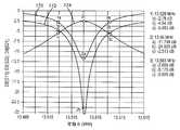
도 4는 송신 안테나와 수신 안테나 사이의 커플링 강도를 나타내는 시뮬레이션 결과들을 도시한다. 커브들 (170 및 172) 은, 각각, 송신 및 수신 안테나에 의한 전력 수신 측정치를 나타낸다. 즉, 큰 음수에 관해 매우 근접한 임피던스 매치가 존재하고 대부분의 전력이 수신되며, 그 결과 송신 안테나에 의해 방사된다. 이와 대조적으로, 작은 음수는, 소정의 주파수에서 근접한 임피던스 매치가 존재하지 않기 때문에 대부분의 전력이 안테나로부터 다시 반사된다는 것을 나타낸다. 도 4에서, 송신 안테나 및 수신 안테나는 약 13.56MHz 의 공진 주파수를 갖도록 동조 (tune) 된다.Figure 4 shows simulation results showing the coupling strength between the transmit and receive antennas.
커브 (170) 는 다양한 주파수들에서 송신 안테나로부터 송신된 전력의 양을 나타낸다. 따라서, 약 13.528MHz 및 13.593MHz 에 대응하는 포인트들 (1a 및 3a) 에서, 대부분의 전력이 반사되며 송신 안테나 외부로 송신되지 않는다. 그러나, 약 13.56MHz 에 대응하는 포인트 (2a) 에서, 많은 양의 전력이 수신되고 안테나 외부로 송신된다는 것이 관측될 수 있다.
유사하게, 커브 (172) 는 다양한 주파수들에서 수신 안테나에 의해 수신된 전력의 양을 나타낸다. 따라서, 약 13.528MHz 및 13.593MHz 에 대응하는 포인트들 (1b 및 3b) 에서, 대부분의 전력이 반사되며 수신 안테나를 통해 그리고 수신기로 운반되지 않는다. 그러나, 약 13.56MHz 에 대응하는 포인트 (2b) 에서, 많은 양의 전력이 수신 안테나에 의해 수신되고 수신기로 운반된다는 것이 관측될 수 있다.Similarly,
커브 (174) 는, 송신 안테나를 통해 송신기로부터 전송되고 수신 안테나를 통해 수신되어 수신기로 운반된 이후, 수신기에서 수신된 전력의 양을 나타낸다. 따라서, 약 13.528MHz 및 13.593MHz 에 대응하는 포인트들 (1c 및 3c) 에서, (1) 송신 안테나가 송신기로부터 그 송신 안테나로 전송된 전력의 대부분을 거부하고, (2) 주파수들이 공진 주파수로부터 이격하여 이동함에 따라 송신 안테나와 수신 안테나 사이의 커플링이 덜 효율적이기 때문에, 송신기 외부로 전송된 대부분의 전력은 수신기에서 이용가능하지 않다. 그러나, 약 13.56MHz 에 대응하는 포인트 (2c) 에서, 송신기로부터 전송된 많은 양의 전력이 수신기에서 이용가능하다는 것이 관측될 수 있으며, 이는 송신 안테나와 수신 안테나 사이의 높은 정도의 커플링을 나타낸다.
도 5a 및 5b는 본 발명의 예시적인 실시형태들에 따른, 송신 및 수신 안테나들에 대한 루프 안테나들의 레이아웃들을 도시한다. 루프 안테나들은, 광범위하게 다양한 사이즈들을 갖는 단일 루프들 또는 다중 루프들을 이용하여 다수의 상이한 방식들로 구성될 수도 있다. 또한, 루프들은, 단지 예를 들어 원형, 타원형, 사각형 및 직사각형과 같은 다수의 상이한 형상들일 수도 있다. 도 5a는, 송신 안테나 (114S) 와 동일한 평면 및 송신 안테나 (114S) 의 중심 주변에 배치된 큰 사각 루프 송신 안테나 (114S) 및 작은 사각 루프 수신 안테나 (118) 를 도시한다. 도 5b는, 송신 안테나 (114C) 와 동일한 평면 및 송신 안테나 (114C) 의 중심 주변에 배치된 큰 원형 루프 송신 안테나 (114C) 및 작은 사각 루프 수신 안테나 (118') 를 도시한다. 사각 루프 송신 안테나 (114S) 는 "a" 의 측면 길이를 갖지만, 원형 루프 송신 안테나 (114C) 는 "Φ" 의 직경을 갖는다. 사각 루프에 있어서, 직경이 Φeq=4a/π 로서 정의될 수도 있는 균등한 원형 루프가 존재한다는 것이 관측될 수 있다.Figures 5A and 5B illustrate the layouts of loop antennas for transmit and receive antennas, in accordance with exemplary embodiments of the present invention. The loop antennas may be configured in a number of different ways using single loops or multiple loops having widely varying sizes. The loops may also be a number of different shapes, e.g., only circular, oval, square, and rectangular, for example. 5A shows a large square
도 6은 도 4a 및 4b에 도시된 사각 및 원형 안테나들에 대한 다양한 원주들에 대해 송신 안테나와 수신 안테나 사이의 커플링 강도를 나타낸 시뮬레이션 결과들을 도시한다. 따라서, 커브 (180) 는, 원형 루프 송신 안테나 (114C) 에 대해 다양한 원주 사이즈들에서 원형 루프 송신 안테나 (114C) 와 수신 안테나 (118) 사이의 커플링 강도를 도시한다. 유사하게, 커브 (182) 는, 송신 루프 송신 안테나 (114S) 에 대해 다양한 균등한 원주 사이즈들에서 사각 루프 송신 안테나 (114S) 와 수신 안테나 (118') 사이의 커플링 강도를 도시한다.Figure 6 shows simulation results showing coupling strength between the transmit and receive antennas for the various circumferences for the square and circular antennas shown in Figures 4a and 4b.
도 7은, 도 5a 및 5b에 도시된 사각 및 원형 송신 안테나들에 대한 다양한 표면적에 대해 송신 안테나와 수신 안테나 사이의 커플링 강도를 나타낸 시뮬레이션 결과들을 도시한다. 따라서, 커브 (190) 는 원형 루프 송신 안테나 (114C) 에 대해 다양한 표면적에서 원형 루프 송신 안테나 (114C) 와 수신 안테나 (118) 사이의 커플링 강도를 도시한다. 유사하게, 커브 (192) 는, 송신 루프 송신 안테나 (114S) 에 대해 다양한 표면적에서 사각 루프 송신 안테나 (114S) 와 수신 안테나 (118') 사이의 커플링 강도를 도시한다.Figure 7 shows simulation results showing the coupling strength between the transmit and receive antennas for various surface areas for the square and circular transmit antennas shown in Figures 5A and 5B. The
도 8은 동일 평면 및 동축 배치들에서의 커플링 강도들을 나타내기 위해 송신 안테나에 관한 수신 안테나에 대해 다양한 배치 포인트들을 도시한다. 여기에서 사용된 바와 같이, "동일 평면" 은, 송신 안테나 및 수신 안테나가, 실질적으로 정렬되고 (즉, 실질적으로 동일한 방향으로 포인팅하는 표면 법선들을 갖고) 송신 안테나의 평면과 수신 안테나의 평면 사이에 거리가 없는 (또는 작은 거리의) 평면을 갖는다는 것을 의미한다. 여기에서 사용된 바와 같이, "동축" 은, 송신 안테나 및 수신 안테나가, 실질적으로 정렬되고 (즉, 실질적으로 동일한 방향으로 포인팅하는 표면 법선들을 갖고) 2개의 평면들 사이의 거리가 사소하지 않으며 또한 송신 안테나 및 수신 안테나의 표면 법선이 동일한 벡터를 실질적으로 따라 놓여지거나 2개의 법선들이 편대 (echelon) 로 존재하는 평면을 갖는다는 것을 의미한다.8 shows various placement points for a receive antenna with respect to a transmit antenna to represent coupling intensities in coplanar and coaxial arrangements. As used herein, "coplanar" means that the transmitting and receiving antennas are substantially aligned (i. E., With surface normals pointing in substantially the same direction) between the plane of the transmitting antenna and the plane of the receiving antenna Meaning that it has a plane with no distance (or a small distance). As used herein, "coaxial" means that the transmit and receive antennas are substantially aligned (i. E., Have surface normals pointing in substantially the same direction) and the distance between the two planes is not trivial Means that the surface normals of the transmit and receive antennas are placed substantially along the same vector or that the two normals have planes that are present in an echelon.
예로서, 포인트들 (p1, p2, p3, 및 p7) 은, 송신 안테나에 대한 수신 안테나에 대해 모두 동일 평면 배치 포인트들이다. 또 다른 예로서, 포인트 (p5 및 p6) 는 송신 안테나에 대한 수신 안테나에 대해 동축 배치 포인트들이다. 아래의 표는 도 8에 도시된 다양한 배치 포인트들 (p1 내지 p7) 에서의 (수신 안테나에 도달한 송신 안테나로부터 송신된 전력의 퍼센트로서 표현되는) 커플링 효율도 및 커플링 강도 (S21) 를 나타낸다.By way of example, points p1, p2, p3, and p7 are all coplanar placement points for a receive antenna for a transmit antenna. As another example, points p5 and p6 are coaxial placement points for the receive antenna for the transmit antenna. The table below shows the coupling efficiency and coupling strength S21 (expressed as a percentage of the power transmitted from the transmit antenna that reached the receive antenna) at various placement points p1 through p7 shown in FIG. 8 .

관측될 수 있는 바와 같이, 동일 평면 배치 포인트들 (p1, p2, 및 p3) 모두는 비교적 높은 커플링 효율도를 나타낸다. 배치 포인트 (p7) 또한 동일 평면 배치 포인트이지만, 송신 루프 안테나 외부에 있다. 배치 포인트 (p7) 가 높은 커플링 효율도를 갖지 않지만, 몇몇 커플링이 존재하고 커플링-모드 영역이 송신 루프 안테나의 페리미터 (perimeter) 를 넘어 확장한다는 것이 명백하다.As can be observed, all of the coplanar placement points (p1, p2, and p3) exhibit a relatively high coupling efficiency. Placement point p7 is also coplanar placement point, but outside the transmit loop antenna. It is clear that although the placement point p7 does not have a high coupling efficiency, there are some couplings and the coupling-mode region extends beyond the perimeter of the transmission loop antenna.
배치 포인트 (p5) 는 송신 안테나와 동축이며, 실질적인 커플링 효율도를 나타낸다. 배치 포인트 (p5) 에 대한 커플링 효율도는 동일 평면 배치 포인트들에 대한 커플링 효율도만큼 높지는 않다. 그러나, 배치 포인트 (p5) 에 대한 커플링 효율도는, 실질적인 전력이 동축 배열내의 송신 안테나와 수신 안테나 사이에서 운반될 수 있기에는 충분히 높다.The placement point p5 is coaxial with the transmitting antenna and exhibits substantial coupling efficiency. The coupling efficiency for placement point p5 is not as high as the coupling efficiency for coplanar placement points. However, the coupling efficiency for placement point p5 is high enough so that substantial power can be carried between the transmit and receive antennas in the coaxial array.
배치 포인트 (p4) 는 송신 안테나의 원주 내에 존재하지만, 오프셋 동축 배치 (즉, 실질적으로 동일한 방향이지만 상이한 위치에 있는 표면 법선들을 가짐) 또는 오프셋 동일 평면 (즉, 실질적으로 동일한 방향의 표면 법선을 갖지만 서로에 대해 오프셋된 평면을 가짐) 으로서 지칭될 수도 있는 위치에서 송신 안테나의 평면 위에 약간의 간격으로 존재한다. 표로부터, 2.5cm 의 오프셋 거리에 관해, 배치 포인트 (p4) 가 비교적 양호한 커플링 효율도를 여전히 갖는다는 것이 관측될 수 있다.The placement point p4 is within the circumference of the transmit antenna but may be offset coaxially (i.e., having substantially the same direction but having surface normals at different positions) or offset coplanar (i.e., having a surface normal of substantially the same direction At some distance above the plane of the transmit antenna at a location that may be referred to as < RTI ID = 0.0 > a < / RTI > It can be seen from the table that, for an offset distance of 2.5 cm, placement point p4 still has a relatively good coupling efficiency.
배치 포인트 (p6) 는, 송신 안테나의 원주 외부에 존재하고 송신 안테나의 평면 위에 실질적인 거리에 있는 배치 포인트를 도시한다. 표로부터 관측될 수 있는 바와 같이, 배치 포인트 (p7) 는 송신 안테나와 수신 안테나 사이에 커플링 효율도가 거의 없다는 것을 나타낸다.Placement point p6 shows placement points that are external to the circumference of the transmit antenna and are at a substantial distance above the plane of the transmit antenna. As can be observed from the table, placement point p7 indicates that there is little coupling efficiency between the transmit and receive antennas.
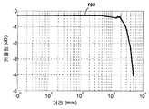
도 9는 송신 안테나와 수신 안테나 사이의 다양한 거리들에서 동축 배치에 대한 커플링 강도를 나타내는 시뮬레이션 결과들을 도시한다. 도 9에 대한 시뮬레이션들은, 동축 배치이지만 약 1.2 미터의 측면들을 갖고 10MHz 의 송신 주파수에 있는 사각형 송신 및 수신 안테나들에 대한 것이다. 커플링 강도가 약 0.5 미터 미만의 거리에서 매우 높고 균일하게 유지된다는 것이 관측될 수 있다.Figure 9 shows simulation results showing coupling strength for coaxial placement at various distances between the transmit and receive antennas. The simulations for FIG. 9 are for the square transmit and receive antennas, which are coaxial but have sides of about 1.2 meters and at a transmit frequency of 10 MHz. It can be observed that the coupling strength remains very high and uniform at distances of less than about 0.5 meters.
도 10은 본 발명의 예시적인 실시형태에 따른 송신기의 간략화된 블록도이다. 송신기 (200) 는 송신 회로 (202) 및 송신 안테나 (204) 를 포함한다. 일반적으로, 송신 회로 (202) 는, 송신 안테나 (204) 에 관한 근접장 에너지의 생성을 초래하는 오실레이팅 신호를 제공함으로써 송신 안테나 (204) 에 RF 전력을 제공한다. 예로서, 송신기 (200) 는 13.56MHz ISM 대역에서 동작할 수도 있다.10 is a simplified block diagram of a transmitter in accordance with an exemplary embodiment of the present invention. The
예시적인 송신 회로 (202) 는, 송신 회로 (202) 의 임피던스 (예를 들어, 50옴) 를 송신 안테나 (204) 에 매칭시키기 위한 고정된 임피던스 매칭 회로 (206), 및 수신기 (108; 도 1) 에 커플링된 디바이스들의 자체-재밍을 방지하기 위한 레벨로 하모닉 방출을 감소시키도록 구성된 저역 통과 필터 (LPF; 208) 를 포함한다. 다른 실시형태들은, 다른 주파수들을 통과하면서 특정한 주파수들을 감쇠시키는 노치 필터들을 포함하지만 이에 제한되지는 않는 상이한 필터 토폴로지들을 포함할 수도 있으며, 전력 증폭기에 의한 DC 전류 인출 또는 안테나로의 출력 전력과 같이 측정가능한 송신 메트릭들에 기초하여 변할 수 있는 적응성 임피던스 매치를 포함할 수도 있다. 송신 회로 (202) 는, 오실레이터 (212) 에 의해 결정된 바와 같은 RF 신호를 유도하도록 구성된 전력 증폭기 (210) 를 더 포함한다. 송신 회로는 별개의 디바이스들 또는 회로들로 구성될 수도 있거나, 대안적으로는 집적 어셈블리로 구성될 수도 있다. 송신 안테나 (204) 로부터 출력된 예시적인 RF 전력은 약 2.5 와트일 수도 있다.The exemplary transmit
송신 회로 (202) 는, 특정 수신기들에 대해 송신 페이즈 (또는 듀티 사이클) 동안 오실레이터 (212) 를 인에이블시키고, 그 오실레이터의 주파수를 조정하며, 이웃한 디바이스들과 그들의 부착된 수신기들을 통해 상호작용하기 위한 통신 프로토콜을 구현하기 위해 출력 전력 레벨을 조정하기 위한 프로세서 (214) 를 더 포함한다.The transmit
송신 회로 (202) 는, 송신 안테나 (204) 에 의해 생성된 근접장의 근방에서 활성 수신기들의 존재 또는 부존재를 검출하기 위한 로드 감지 회로 (216) 를 더 포함할 수도 있다. 예로서, 로드 감지 회로 (216) 는, 송신 안테나 (204) 에 의해 생성된 근접장의 근방에서의 활성 수신기들의 존재 또는 부존재에 의해 영향을 받는, 전력 증폭기 (210) 로 흐르는 전류를 모니터링한다. 전력 증폭기 (210) 상의 로드에 대한 변화의 검출은, 활성 수신기와 통신하도록 에너지를 송신하기 위해 오실레이터 (212) 를 인에이블시킬 지를 판정할 시에 사용하기 위하여 프로세서 (214) 에 의해 모니터링된다.The transmit
송신 안테나 (204) 는, 저항 손실들을 낮게 유지하도록 선택된 두께, 폭 및 금속 타입을 갖는 안테나 스트립으로서 구현될 수도 있다. 종래의 구현에서, 송신 안테나 (204) 는 일반적으로, 책상, 매트, 램프 또는 다른 덜 휴대적인 구성과 같은 더 큰 구조와 연결시키도록 구성될 수 있다. 따라서, 송신 안테나 (204) 는 일반적으로, 실제 디멘션을 갖기 위해 "턴" 을 필요로 하지 않을 것이다. 송신 안테나 (204) 의 예시적인 구현은 "전기적으로 작을 (즉, 파장의 프랙션 (fraction))" 수도 있고, 공진 주파수를 정의하기 위해 커패시터들을 사용함으로써 더 낮은 사용가능한 주파수들에서 공진하도록 동조될 수도 있다. 수신 안테나에 대해 송신 안테나 (204) 가 직경 또는 사각 루프라면 측면의 길이 (예를 들어, 0.50 미터) 가 더 클 수도 있는 예시적인 애플리케이션에서, 송신 안테나 (204) 는 합당한 커패시턴스를 획득하기 위해 큰 수의 턴들을 반드시 필요로 하지는 않을 것이다.The transmit
도 11은 본 발명의 일 실시형태에 따른 수신기의 블록도이다. 수신기 (300) 는 수신 회로 (302) 및 수신 안테나 (304) 를 포함한다. 또한, 수신기 (300) 는 수신 전력을 그에 제공하기 위해 디바이스 (350) 에 커플링한다. 수신기 (300) 가 디바이스 (350) 외부에 존재하는 것으로 도시되어 있지만 디바이스 (350) 내로 통합될 수도 있음을 유의해야 한다. 일반적으로, 에너지는 수신 안테나 (304) 에 무선으로 전파되고, 그 후, 수신 회로 (302) 를 통해 디바이스 (350) 에 커플링된다.11 is a block diagram of a receiver in accordance with an embodiment of the present invention. The
수신 안테나 (304) 는 송신 안테나 (204; 도 10) 와 동일한 주파수 또는 동일한 주파수 근방에서 공진하도록 동조된다. 수신 안테나 (304) 는 송신 안테나 (204) 와 유사하게 디멘션될 수도 있거나, 관련 디바이스 (350) 의 디멘션에 기초하여 상이하게 사이징될 수도 있다. 예로서, 디바이스 (350) 는 송신 안테나 (204) 의 길이의 직경보다 작은 직경 또는 길이 디멘션을 갖는 휴대용 전자 디바이스일 수도 있다. 그러한 예에서, 수신 안테나 (304) 는, 동조 커패시터 (미도시) 의 커패시턴스 값을 감소시키고 수신 안테나의 임피던스를 증가시키기 위해 멀티-턴 안테나로서 구현될 수도 있다. 예로서, 수신 안테나 (304) 는, 안테나 직경을 최대화하고 수신 안테나의 루프 턴 (즉, 권선) 의 수 및 상호-권선 커패시턴스의 수를 감소시키기 위해 디바이스 (350) 의 실질적인 원주 주변에 배치될 수도 있다.The receive
수신 회로 (302) 는 수신 안테나 (304) 에 수신 안테나 (304) 에 임피던스 매치를 제공한다. 수신 회로 (302) 는, 디바이스 (350) 에 의한 사용을 위해 충전 전력으로 RF 에너지 소스를 변환시키기 위한 전력 변환 회로 (306) 를 포함한다. 전력 변환 회로 (306) 는 RF-DC 변환기 (308) 를 포함하며, DC-DC 변환기 (310) 를 더 포함할 수도 있다. RF-DC 변환기 (308) 는 수신 안테나 (304) 에서 수신된 RF 에너지 신호를 비-교류 전력으로 정류하지만, DC-DC 변환기 (310) 는 디바이스 (350) 와 호환가능한 에너지 전위 (예를 들어, 전압) 로 그 정류된 RF 에너지 신호를 변환시킨다. 부분 및 풀 정류기들, 조정기들, 브리지들, 더블러 (doubler) 들 뿐만 아니라 선형 및 스위칭 변환기들을 포함하는 다양한 RF-DC 변환기들이 고려된다.The receiving
수신 회로 (302) 는, 수신 안테나 (304) 를 전력 변환 회로 (306) 에 접속시키거나, 대안적으로는 전력 변환 회로 (306) 를 접속해제시키기 위한 스위칭 회로 (312) 를 더 포함할 수도 있다. 아래에서 더 상세히 설명될 바와 같이, 전력 변환 회로 (306) 로부터 수신 안테나 (304) 를 접속해제시키는 것은, 디바이스 (350) 의 충전을 서스펜드 (suspend) 시킬 뿐만 아니라 송신기 (200; 도 2) 에 이해 "관측되는" 바와 같은 "로드" 를 변경시킨다. 상술된 바와 같이, 송신기 (200) 는 송신기 전력 증폭기 (210) 에 제공되는 바이어스 전류에서의 변동들을 검출하는 로드 감지 회로 (216) 를 포함한다. 따라서, 송신기 (200) 는 수신기들이 송신기의 근접장에 존재하는 시간을 결정하기 위한 메커니즘을 갖는다.The receiving
다수의 수신기들 (300) 이 송신기의 근접장에 존재할 경우, 하나 이상의 수신기들의 로딩 및 언로딩을 시간-멀티플렉싱하여, 다른 수신기들이 송신기에 더 효율적으로 커플링하게 할 수 있는 것이 바람직할 수도 있다. 또한, 수신기는, 다른 인접한 수신기들로의 커플링을 제거하거나 인접한 송신기들 상의 로딩을 감소시키기 위해 클로우킹 (cloak) 될 수도 있다. 또한, 수신기의 "언로딩" 은 "클로우킹" 으로서 여기에 알려진다. 또한, 수신기 (300) 에 의해 제어되고 송신기 (200) 에 의해 검출되는 언로딩과 로딩 사이의 이러한 스위칭은, 아래에 더 상세히 설명될 바와 같이 수신기 (300) 로부터 송신기 (200) 로의 통신 메커니즘을 제공한다. 또한, 수신기 (300) 로부터 송신기 (200) 로의 메시지의 전송을 인에이블시키는 스위칭과 프로토콜이 관련될 수 있다. 예로서, 스위칭 스피드는 약 100μ초일 수도 있다.It may be desirable to time-multiplex the loading and unloading of one or more receivers when
수신 회로 (302) 는, 송신기로부터 수신기로의 정보 시그널링에 대응할 수도 있는 수신 에너지 변동들을 식별하는데 사용되는 시그널링 검출기 및 비컨 회로 (314) 를 더 포함할 수도 있다. 또한, 시그널링 및 비컨 회로 (314) 는, 감소된 RF 신호 에너지 (즉, 비컨 신호) 의 송신을 검출하며, 무선 충전을 위하여 수신 회로 (302) 를 구성하기 위해 수신 회로 (302) 내의 전력공급받지 않거나 전력-고갈된 회로들 중 어느 하나를 기상시키도록 공칭 전력으로 그 감소된 RF 신호 에너지를 정류시키는데 또한 사용될 수도 있다.Receiving
수신 회로 (302) 는, 여기에 설명된 스위칭 회로 (312) 의 제어를 포함하는 여기에 설명된 수신기 (300) 의 프로세스들을 조정하기 위한 프로세서 (316) 를 더 포함한다. 또한, 수신기의 클로우킹은, 충전 전력을 디바이스 (350) 에 제공하는 외부 유선 충전 소스 (예를 들어, 월 (wall)/USB 전력) 의 검출을 포함하는 다른 이벤트들의 발생 시에 발생할 수도 있다. 또한, 프로세서 (316) 는 수신기의 클로우킹을 제어하는 것 이외에, 비컨 상태를 결정하고 송신기로부터 전송된 메시지들을 추출하기 위해 비컨 회로 (314) 를 모니터링할 수도 있다. 또한, 프로세서 (316) 는 개선된 성능을 위해 DC-DC 변환기 (310) 를 조정할 수도 있다.The receiving
도 12는 송신기와 수신기 사이의 메시징을 수행하기 위한 송신 회로의 일부의 간략화된 개략도를 도시한다. 본 발명의 몇몇 예시적인 실시형태들에서, 통신 수단이 송신기와 수신기 사이에서 인에이블될 수도 있다. 도 12에서, 전력 증폭기 (210) 는 송신 안테나 (204) 를 구동시켜, 방사 필드를 생성한다. 전력 증폭기는, 송신 안테나 (204) 에 대해 원하는 주파수에서 오실레이팅하는 캐리어 신호 (220) 에 의해 구동된다. 송신 변조 신호 (224) 는 전력 증폭기 (210) 의 출력을 제어하는데 사용된다.12 shows a simplified schematic diagram of a portion of a transmission circuit for performing messaging between a transmitter and a receiver. In some exemplary embodiments of the invention, the communication means may be enabled between the transmitter and the receiver. In Fig. 12, the
송신 회로는 전력 증폭기 (210) 에 대해 온/오프 키잉 프로세스를 사용함으로써 수신기들로 신호들을 전송할 수 있다. 즉, 송신 변조 신호 (224) 가 어써트 (assert) 될 경우, 전력 증폭기 (210) 는 송신 안테나 (204) 상에서 캐리어 신호 (220) 의 주파수를 드라이빙 아웃할 것이다. 송신 변조 신호 (224) 가 무효화되면, 전력 증폭기는 송신 안테나 (204) 상에서 임의의 주파수를 드라이빙 아웃하지 않을 것이다.The transmit circuitry may transmit signals to the receivers by using an on / off keying process on the
또한, 도 12의 송신 회로는, 전력을 전력 증폭기 (210) 에 공급하고 수신 신호 (235) 출력을 생성하는 로드 감지 회로 (216) 를 포함한다. 로드 감지 회로 (216) 에서, 저항기 RS 에 걸친 전압 드롭은 신호 (226) 에서의 전력과 전력 증폭기 (210) 로의 전력 공급 (228) 사이에서 전개된다. 전력 증폭기 (210) 에 의해 소비되는 전력에서의 임의의 변화는, 차동 증폭기 (230) 에 의해 증폭될 전압 드롭에서의 변화를 초래할 것이다. 송신 안테나가 수신기 (도 12에는 도시되지 않음) 의 수신 안테나와의 커플링 모드에 있을 경우, 전력 증폭기 (210) 에 의해 인출되는 전류의 양은 변할 것이다. 즉, 커플링 모드 공진이 송신 안테나 (210) 에 대해 존재하지 않으면, 방사 필드를 구동하는데 요구되는 전력이 제 1 양일 것이다. 커플링 모드 공진이 존재하면, 전력의 대부분이 수신 안테나에 커플링되기 때문에, 전력 증폭기 (210) 에 의해 소비되는 전력의 양은 상승할 것이다. 따라서, 후술될 바와 같이, 수신 신호 (235) 는 송신 안테나 (235) 에 커플링된 수신 안테나의 존재를 나태날 수 있고, 또한, 수신 안테나로부터 전송된 신호들을 검출할 수 있다. 또한, 후술될 바와 같이, 인출된 수신기 전류에서의 변화는 인출된 송신기의 전력 증폭기 전류에서 관측가능할 것이며, 이러한 변화는 수신 안테나들로부터의 신호들을 검출하는데 사용될 수 있다.12 also includes a
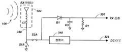
도 13a 내지 13c는 수신기와 송신기 사이의 메시징을 나타내기 위해 다양한 상태들에서의 수신 회로의 일부의 간략화된 개략도를 도시한다. 도 13a 내지 13c 모두는 동일한 회로 엘리먼트들을 도시하며, 차이는 다양한 스위치들의 상태이다. 수신 안테나 (304) 는 노드 (350) 를 구동시키는 특성 인덕턴스 L1 를 포함한다. 노드 (350) 는 스위치 S1A 를 통해 접지에 선택적으로 커플링된다. 또한, 노드 (350) 는 스위치 S1B 를 통해 다이오드 D1 및 정류기 (318) 에 선택적으로 커플링된다. 정류기 (318) 는 DC 전력 신호 (322) 를 수신 디바이스 (미도시) 에 공급하여, 그 수신 디바이스에 전력공급하고, 배터리를 충전하거나, 이들의 조합을 행한다. 다이오드 D1 는, 커패시터 C3 및 저항기 R1 에 대한 하모닉 및 원치않는 주파수들을 제거하도록 필터링되는 송신 신호 (320) 에 커플링된다. 따라서, D1, C3, 및 R1 의 조합은, 도 12의 송신기를 참조하여 상술된 송신 변조 신호 (224) 에 의해 생성되는 송신 변조를 모방하는 송신 신호 (320) 에 대해 신호를 생성할 수 있다.13A-13C show a simplified schematic diagram of a portion of the receiving circuitry in various states to illustrate messaging between the receiver and the transmitter. 13A to 13C all show the same circuit elements, with the difference being the state of the various switches. The receive
본 발명의 예시적인 실시형태들은, 역방향 링크 시그널링을 달성하기 위해, 수신 디바이스의 전류 인출의 변조 및 수신 안테나의 임피던스의 변조를 포함한다. 도 13a 및 도 12 양자를 참조하면, 수신 디바이스의 전력 인출이 변함에 따라, 로드 감지 회로 (216) 는 송신 안테나 상의 결과적인 전력 변화들을 검출하며, 이들 변화들로부터 수신 신호 (235) 를 생성할 수 있다.Exemplary embodiments of the present invention include modulating the current draw of the receiving device and modulating the impedance of the receiving antenna to achieve reverse link signaling. Referring to both FIGS. 13A and 12, as the power draw of the receiving device changes, the
도 13a 내지 13c의 실시형태에서, 송신기를 통한 전류 인출은, 스위치들 S1A 및 S2A 의 상태를 변화시킴으로써 변경될 수 있다. 도 13a에서, 스위치 S1A 및 스위치 S2A 양자가 개방되어, "DC 개방 상태" 를 생성하고, 송신 안테나 (204) 로부터 로드를 본질적으로 제거한다. 이것은 송신기에 의해 관측되는 전류를 감소시킨다.In the embodiment of Figures 13A-13C, the current draw through the transmitter can be changed by changing the state of the switches S1A and S2A. In Fig. 13A, both switch S1A and switch S2A are open, creating a "DC open state " and essentially eliminating the load from transmit
도 13b에서, 스위치 S1A 가 폐쇄되고 스위치 S2A 가 개방되어, 수신 안테나 (304) 에 대한 "DC 쇼트 (short) 상태" 를 생성한다. 따라서, 도 13b의 상태는 송신기에서 관측되는 전류를 증가시키는데 사용될 수 있다.In Fig. 13B, switch S1A is closed and switch S2A is open, creating a "DC short state" for receive
도 13c에서, 스위치 S1A 가 개방되고 스위치 S2A 가 폐쇄되어, 노멀 수신 모드 (또한, "DC 동작 상태" 로 지칭됨) 를 생성하며, 여기서, 전력은 DC 아웃 신호 (322) 에 의해 공급될 수 있고, 송신 신호 (320) 가 검출될 수 있다. 도 13c에 도시된 상태에서, 수신기는 일반적인 양의 전력을 수신하며, 따라서, DC 개방 상태 또는 DC 쇼트 상태보다 송신 안테나로부터 전력을 더 또는 덜 소비한다.In FIG. 13C, switch S1A is open and switch S2A is closed, creating a normal receive mode (also referred to as a “DC operating state”), where power can be supplied by DC out
역방향 링크 시그널링은, DC 동작 상태 (도 13c) 와 DC 쇼트 상태 (도 13b) 사이의 스위칭에 의해 달성될 수도 있다. 또한, 역방향 링크 시그널링은, DC 동작 상태 (도 13c) 와 DC 개방 상태 (도 13a) 사이의 스위칭에 의해 달성될 수도 있다.Reverse link signaling may be achieved by switching between a DC operating state (FIG. 13C) and a DC shorted state (FIG. 13B). In addition, reverse link signaling may be accomplished by switching between a DC operating state (FIG. 13C) and a DC open state (FIG. 13A).
도 14a 내지 14c는 수신기와 송신기 사이의 메시징을 나타내기 위해 다양한 상태에서 대안적인 수신 회로의 일부의 간략화된 개략도를 도시한다.14A-14C show a simplified schematic diagram of a portion of an alternative receiving circuit in various states to illustrate messaging between the receiver and the transmitter.
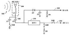
도 14a 내지 14c 모두는 동일한 회로 엘리먼트들을 도시하지만, 차이는 다양한 스위치들의 상태이다. 수신 안테나 (304) 는 노드 (350) 를 구동시키는 특성 인덕턴스 L1 를 포함한다. 노드 (350) 는 커패시터 C1 및 스위치 S1B 를 통해 접지에 선택적으로 커플링된다. 또한, 노드 (350) 는 커패시터 C2 를 통해 다이오드 D1 및 정류기 (318) 에 AC 커플링된다. 다이오드 D1 는, 커패시터 C3 및 저항기 R1 에 대한 하모닉 및 원치않는 주파수들을 제거하도록 필터링되는 송신 신호 (320) 에 커플링된다. 따라서, D1, C3 및 R1 의 조합은, 도 12를 참조하여 상술된 송신 변조 신호 (224) 에 의해 생성되는 송신 변조를 모방하는 송신 신호 (320) 에 대해 신호를 생성할 수 있다.14A to 14C all show the same circuit elements, but the difference is the state of the various switches. The receive
정류기 (318) 는, 저항기 R2 및 접지와 직렬로 접속된 스위치 S2B 에 접속된다. 또한, 정류기 (318) 는 스위치 S3B 에 접속된다. 스위치 S3B 의 다른 측면은 DC 전력 신호 (322) 를 수신 디바이스 (미도시) 에 공급하여, 그 수신 디바이스에 전력공급하고, 배터리를 충전하거나, 이들의 조합을 행한다.The
도 13a 내지 13c에서, 수신 안테나 (304) 의 DC 임피던스는 스위치 S1B 를 통해 수신 안테나를 접지에 선택적으로 커플링시킴으로써 변경된다. 이와 대조적으로 도 14a 내지 14c의 실시형태들에서, 안테나의 임피던스는, 수신 안테나 (304) 의 AC 임피던스를 변경시키기 위해 스위치들 S1B, S2B, 및 S3B 의 상태를 변경시킴으로써 역방향 링크 시그널링을 생성하도록 변화될 수 있다. 도 14a 내지 14c에서, 수신 안테나 (304) 의 공진 주파수는 커패시터 C2 로 동조될 수도 있다. 따라서, 수신 안테나 (304) 의 AC 임피던스는, 스위치 S1B 를 사용하여 커패시터 C1 을 통해 수신 안테나 (304) 를 선택적으로 커플링시킴으로써 변경될 수도 있으며, 송신 안테나와 최적으로 커플링할 범위 외부에 있을 상이한 주파수로 공진 회로를 본질적으로 변경시킨다. 수신 안테나 (304) 의 공진 주파수가 송신 안테나의 공진 주파수 근방에 존재하고 수신 안테나 (304) 가 송신 안테나의 근접장에 존재하면, 커플링 모드가 전개될 수도 있으며, 여기서, 수신기는 방사 필드 (106) 로부터 상당한 전력을 인출할 수 있다.13A-13C, the DC impedance of the receive
도 14a에서, 스위치 S1B 가 폐쇄되며, 이는 안테나를 디튜닝 (de-tune) 하고 "AC 클로우킹 상태" 를 생성하며, 수신 안테나가 송신 안테나의 주파수에서 공진하지 않기 때문에 송신 안테나 (204) 에 의한 검출로부터 수신 안테나 (304) 를 본질적으로 "클로우킹" 한다. 수신 안테나가 커플링 모드에 존재하지 않을 것이므로, 스위치들 S2B 및 S3B 의 상태는 본 설명에서는 특별히 중요하지는 않다.In Fig. 14A, switch S1B is closed, which de-tune the antenna and generates an "AC clking state ", and the receive antenna is not resonant at the frequency of the transmit antenna, Essentially "cloaking" the receive
도 14b에서, 스위치 S1B 가 개방되고 스위치 S2B 가 폐쇄되며 스위치 S3B 가 개방되어, 수신 안테나 (304) 에 대해 "동조된 더미-로드 상태" 를 생성한다. 스위치 S1B 가 개방이기 때문에, 커패시터 C1 는 공진 회로에 기여하지 않고, 커패시터 C2 와 연결된 수신 안테나 (304) 는 송신 안테나의 공진 주파수와 매칭할 수도 있는 공진 주파수에 존재할 것이다. 스위치 S3B 개방 및 스위치 S2B 폐쇄의 조합은 정류기에 대해 비교적 높은 전류 더미 로드를 생성하며, 이는 수신 안테나 (320) 를 통해 더 많은 전력을 인출할 것이고 송신 안테나에 의해 감지될 수 있다. 또한, 수신 안테나가 송신 안테나로부터 전력을 수신하기 위한 상태에 있으므로, 송신 신호 (320) 가 검출될 수 있다.In Fig. 14B, switch S1B is open, switch S2B is closed, and switch S3B is open, creating a "tuned dummy-load state" Because the switch S1B is open, the capacitor C1 does not contribute to the resonant circuit, and the receive
도 14c에서, 스위치 S1B 가 개방되고 스위치 S2B 가 개방되며 스위치 S3B 가 폐쇄되어, 수신 안테나 (304) 에 대해 "동조된 동작 상태" 를 생성한다. 스위치 S1B 가 개방되기 때문에, 커패시터 C1 는 공진 회로에 기여하지 않고, 커패시터 C2 와 연결된 수신 안테나 (304) 는 송신 안테나의 공진 주파수와 매칭할 수도 있는 공진 주파수에 존재할 것이다. 스위치 S2B 개방 및 스위치 S3B 폐쇄의 조합은 노멀 동작 상태를 생성하며, 여기서, 전력이 DC 아웃 신호 (322) 에 의해 공급될 수 있고 송신 신호 (320) 가 검출될 수 있다.In Fig. 14C, switch S1B is open, switch S2B is open, and switch S3B is closed, creating a "tuned operating state" Since the switch S1B is open, the capacitor C1 does not contribute to the resonant circuit, and the receiving
역방향 링크 시그널링은, 동조된 동작 상태 (도 14c) 와 AC 클로우킹 상태 (도 14a) 사이의 스위칭에 의해 달성될 수도 있다. 또한, 역방향 링크 시그널링은, 동조된 더미-로드 상태 (도 14b) 와 AC 클로우킹 상태 (도 14a) 사이의 스위칭에 의해 달성될 수도 있다. 또한, 역방향 링크 시그널링은, 송신기의 로드 감지 회로에 의해 검출될 수 있는, 수신기에 의해 소비되는 전력의 양에서의 차이가 존재하기 때문에, 동조된 동작 상태 (도 14c) 와 동조된 더미-로드 상태 (도 14b) 사이의 시그널링에 의해 달성될 수도 있다.Reverse link signaling may be accomplished by switching between a tuned operating state (FIG. 14C) and an AC locked state (FIG. 14A). In addition, reverse link signaling may be achieved by switching between a synchronized dummy-load state (Figure 14b) and an AC clking state (Figure 14a). In addition, the reverse link signaling can be detected in a dummy-load state (Fig. 14C) synchronized with the tuned operating state (Fig. 14C), since there is a difference in the amount of power consumed by the receiver, (Fig. 14B).
물론 당업자는, 스위치들 S1B, S2B, 및 S3B 의 다른 조합들이 클로우킹을 생성하고, 역방향 링크 시그널링을 생성하며, 전력을 수신 디바이스에 공급하는데 사용될 수도 있음을 인식할 것이다. 또한, 스위치들 S1A 및 S1B 는 클로우킹, 역방향 링크 시그널링, 및 전력을 수신 디바이스에 공급하기 위한 다른 가능한 조합들을 생성하기 위해 도 14a 내지 14c의 회로들에 부가될 수도 있다.Of course, those skilled in the art will recognize that other combinations of switches S1B, S2B, and S3B may be used to generate the cloaking, generate the reverse link signaling, and supply power to the receiving device. In addition, switches S1A and S1B may be added to the circuits of Figs. 14A-14C to generate cloaking, reverse link signaling, and other possible combinations for supplying power to the receiving device.
따라서, 도 12를 참조하여 상술된 바와 같이, 커플링 모드에 있을 경우, 신호들은 송신기로부터 수신기로 전송될 수도 있다. 또한, 도 13a 내지 13c 및 14a 내지 14c를 참조하여 상술된 바와 같이, 커플링 모드에 있을 경우, 신호들은 수신기로부터 송신기로 전송될 수도 있다.Thus, as described above with reference to FIG. 12, when in the coupling mode, signals may be transmitted from the transmitter to the receiver. Also, as described above with reference to Figs. 13A to 13C and 14A to 14C, when in the coupling mode, signals may be transmitted from the receiver to the transmitter.
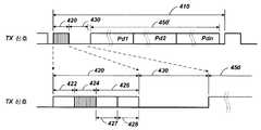
도 15a 내지 15c는 상술된 시그널링 기술들을 사용하여 송신기와 수신기 사이에서의 통신을 위한 메시징 프로토콜을 도시한 타이밍도들이다. 일 예시적인 접근법에서, 송신기로부터 수신기로의 신호들은 여기에서 "순방향 링크" 로서 지칭되며, 노멀 오실레이션과 오실레이션 없음 사이의 간단한 AM 변조를 사용한다. 또한, 다른 변조 기술들이 고려된다. 비-제한적인 예로서, 존재하는 신호는 1로서 해석될 수도 있고, 존재하지 않는 신호는 0으로서 해석될 수도 있다.15A-15C are timing diagrams illustrating a messaging protocol for communication between a transmitter and a receiver using the signaling techniques described above. In one exemplary approach, the signals from the transmitter to the receiver are referred to herein as "forward link " and use simple AM modulation between normal and no oscillation. Other modulation techniques are also contemplated. As a non-limiting example, an existing signal may be interpreted as 1, and a nonexistent signal may be interpreted as 0.
역방향 링크 시그널링은, 수신 디바이스에 의해 인출된 전력의 변조에 의해 제공되며, 이는 송신기의 로드 감지 회로에 의해 검출될 수 있다. 비-제한적인 예로서, 더 높은 전력 상태들이 1로서 해석될 수도 있고, 더 낮은 전력 상태들이 0으로서 해석될 수도 있다. 수신기가 역방향 링크 시그널링을 수행할 수 있도록 송신기가 온되어야 함을 유의해야 한다. 또한, 수신기는 순방향 링크 시그널링 동안 역방향 링크 시그널링을 수행해야 하지는 않는다. 또한, 2개의 수신 디바이스들이 동일한 시간에서 역방향 링크 시그널링을 수행하기를 시도할 경우, 송신기가 적절한 역방향 링크 신호를 디코딩하는 것이 불가능하지 않다면, 그 수행을 난해하게 할 충돌이 발생할 수도 있다.Reverse link signaling is provided by modulation of the power drawn by the receiving device, which can be detected by the load sensing circuitry of the transmitter. As a non-limiting example, higher power states may be interpreted as 1, and lower power states may be interpreted as 0. It should be noted that the transmitter must be turned on so that the receiver can perform reverse link signaling. Also, the receiver does not have to perform reverse link signaling during forward link signaling. Also, if two receiving devices attempt to perform reverse link signaling at the same time, then if the transmitter is not able to decode the appropriate reverse link signal, a collision may occur that would complicate its performance.
여기에 설명된 예시적인 실시형태에서, 시그널링은, 시작 비트, 데이터 바이트, 패러티 비트 및 정지 비트를 갖는 유니버셜 비동기식 수신 송신 (UART) 시리얼 통신 프로토콜과 유사하다. 물론, 여기에 설명된 본 발명의 예시적인 실시형태를 수행하기 위해 임의의 시리얼 통신 프로토콜이 적절할 수도 있다. 제한이 아닌 설명의 간략화를 위해, 메시징 프로토콜은, 각각의 바이트 송신을 통신하기 위한 주기가 약 10mS 이도록 설명될 것이다.In the exemplary embodiment described herein, the signaling is similar to a Universal Asynchronous Receive Transmit (UART) serial communication protocol with a start bit, a data byte, a parity bit, and a stop bit. Of course, any serial communication protocol may be appropriate for carrying out the exemplary embodiments of the invention described herein. For the sake of simplicity of explanation, but not limitation, the messaging protocol will be described such that the period for communicating each byte transmission is about 10 mS.
도 15a는 메시징 프로토콜의 가장 간단하고 최저의 전력 형태를 도시한다. 동기화 펄스 (420) 는 순환 주기 (410) (예시적인 실시형태에서는 약 1초) 마다 반복될 것이다. 비-제한적인 예로서, 정시의 동기화 펄스는 약 40mS 일 수도 있다. 적어도 동기화 펄스 (420) 를 갖는 순환 주기 (410) 는 송신기가 온인 동안 무한으로 반복될 수도 있다. "화이트" 펄스 (420') 에 의해 도시된 바와 같이, 동기화 펄스 (350) 가 펄스 주기 동안 안정된 주파수일 수도 있기 때문에, "동기화 펄스" 는 다소 잘못된 명칭이다. 또한, 동기화 펄스 (420) 는, 상술되고 "음영" 펄스 (420) 에 의해 도시된 바와 같이, 온/오프 키잉을 이용한 공진 주파수에서의 시그널링을 포함할 수도 있다. 도 15a는 공칭 전력 상태를 도시하며, 여기서, 공진 주파수에서의 전력이 동기화 펄스 (420) 동안 공급되고 송신 안테나가 전력 주기 (450) 동안 오프된다. 모든 수신 디바이스들은, 동기화 펄스 (420) 동안 전력을 수신하도록 허용된다.15A shows the simplest and lowest power form of the messaging protocol.
도 15b는 동기화 펄스 (420), 역방향 링크 주기 (430), 및 전력 주기 (450') 를 갖는 순환 주기 (410) 를 도시하며, 여기서, 송신 안테나는 온이고, 공진 주파수에서 오실레이팅함으로써 풀 전력을 공급하지만 임의의 시그널링을 수행하지는 않는다. 상부의 타이밍도는 전체 순환 주기 (410) 를 도시하고, 하부의 타이밍도는 동기화 펄스 (420) 및 역방향 링크 주기 (430) 의 확대도를 도시한다. 후술될 바와 같이, 전력 주기 (450') 는 다수의 수신 디바이스들에 대한 상이한 주기들로 세그먼트화될 수도 있다. 도 15b는 3개의 상이한 수신 디바이스들에 대한 3개의 전력 세그먼트들 (Pd1, Pd2 및 Pdn) 을 도시한다.Figure 15B shows a
순방향 링크 시그널링이 발생할 경우, 동기화 펄스 (420) 는 웜-업 (warm-up) 주기 (422), 순방향 링크 주기 (424), 및 청취 주기 (426) 를 포함할 수도 있다. 청취 주기 (426) 는 핸드오버 주기 (427) 및 역방향 링크 시작 주기 (428) 를 포함할 수도 있다. 동기화 펄스 (420) 동안, 송신기는 ("음영" 섹션에 의해 표시되는) 순방향 링크 주기 (400) 동안 순방향 링크 메시지를 전송하고, 청취 주기 (426) 동안 수신기로부터의 응답을 대기한다. 도 15b에서, 수신기가 응답하지 않으며, 이는 청취 주기 (426) 동안의 "화이트" 섹션에 의해 표시된다.When forward link signaling occurs, the
도 15c는, "십자-음영" 섹션들에 의해 표시된 바와 같은 역방향 링크 시작 주기 (428) 및 역방향 링크 주기 (430) 동안 수신기가 응답한다는 것을 제외하고, 도 15b와 유사하다. 도 15에서, 동기화 펄스 (420) 동안, 송신기는 순방향 링크 주기 (400) 동안 순방향 링크 메시지를 전송하고, 청취 주기 (426) 동안 수신기로부터의 응답을 대기한다. 응답하는 임의의 수신기들은, 역방향 링크 시작 주기 (428) 및 가급적 역방향 링크 주기 (430) 동안 핸드오버 주기 (427) 의 종료 전에 그들의 응답을 시작한다.15C is similar to FIG. 15B except that the receiver responds during the reverse
비-제한적인 예로서, 표 2는 송신기 및 수신기에 의해 전송될 수도 있는 몇몇 가능한 메시지들을 나타낸다.As a non-limiting example, Table 2 shows some possible messages that may be transmitted by the transmitter and receiver.

여기서,here,
Null = 송신 커맨드 없음;Null = No send command;
DD = 디바이스 넘버;DD = device number;
TT = 디바이스 타입;TT = device type;
PP = 요청된 전력PP = requested power
rr = 랜덤 넘버;rr = random number;
cc = 체크섬;cc = checksum;
NN = 시간 슬롯의 시작; 및NN = start of time slot; And
MM = 시간 슬롯의 종료MM = end of time slot
표 1의 설명에서, 널 커맨드는 순방향 링크 주기 (424) 동안 송신기에 의해 전송된 메시징이 존재하지 않는다는 것을 의미한다. 라인 2에서, 새로운 디바이스 쿼리 (NDQ) 가 송신기에 의해 전송된다. 수신기 디바이스가 응답하면, 수신기는, (디바이스 넘버가 송신기에 의해 할당될 때까지, 새로운 디바이스에 대해 제로이어야 하는) 디바이스 넘버, 전력 요청, 랜덤 넘버, 및 수신기 응답 내의 모든 데이터 비트들의 체크섬과 함께 새로운 디바이스 응답 (NDR) 으로 응답한다.
In the description of Table 1, a null command means that there is no messaging sent by the transmitter during the
*라인 3에서, 새로운 디바이스 쿼리 (DQ) 는 디바이스 넘버와 함께 송신기에 의해 전송된다. DQ에 의해 어드레싱되었던 수신 디바이스는, 디바이스 넘버, 디바이스 타입, 요청된 전력의 양, 및 수신 응답 내의 모든 데이터 비트들의 체크섬과 함께 디바이스 상태 (DS) 로 응답한다.In
라인 4에서, 송신기는 이전의 DQ에 응답하였던 수신기에 확인응답 (ACK) 을 전송한다. ACK에 응답하는 수신기들은 존재하지 않는다.At
라인 5에서, 송신기는, 디바이스 넘버, 전력 주기 (450') 내의 시작 시간, 전력 주기 (450') 내의 종료 시간, 및 수신 응답 내의 모든 데이터 비트들의 체크섬과 함께 슬롯 할당 (SA) 을 전송한다. SA에 응답하는 수신기들은 존재하지 않는다.At
라인 6에서, 송신기는, 모든 수신기들이 그들의 할당된 시간 슬롯들을 사용하는 것을 중지해야 한다는 것을 나타내는 리셋 (RES) 을 전송한다. RES에 응답하는 수신기들은 존재하지 않는다.At
물론, 당업자는, 커맨드들 및 응답들이 예시이고, 본 발명의 범위 내에서 고려되는 다양한 실시형태들이 이들 커맨드들 및 응답들의 변형들을 사용할 수도 있으며, 부가적인 커맨드들 및 응답들이 본 발명의 범위내에서 고려될 수도 있음을 인식할 것이다.Of course, those skilled in the art will appreciate that the various embodiments in which the commands and responses are exemplary and that are contemplated within the scope of the present invention may employ variations of these commands and responses and that additional commands and responses are within the scope of the present invention As will be appreciated by those skilled in the art.
통신이 발생하는 방법을 추가적으로 예시하기 위해, 5개의 상이한 시나리오들이 설명될 것이다. 제 1 시나리오에서, 초기에는, 송신기의 커플링-모드 영역 내에 수신 디바이스들이 존재하지 않으며, 하나의 수신 디바이스가 커플링-모드 영역에 진입한다. 커플링-모드 영역에 디바이스가 존재하지 않을 경우, 송신기는 도 15a에 도시된 바와 같이 저전력 상태로 유지되고 순환 주기 (410) 마다 동기화 펄스 (420) 를 반복할 것이다. 동기화 펄스 (420) 는 순방향 링크 주기 (424) 동안 NDQ를 포함할 것이고, 송신기는 청취 주기 (426) 동안 응답을 청취할 것이다. 수신된 응답이 존재하지 않으면, 다음의 순환 주기 (410) 의 동기화 펄스 (420) 에 대한 시간까지, 송신기는 셧다운된다.
To further illustrate how communication occurs, five different scenarios will be described. In a first scenario, initially, there are no receiving devices in the coupling-mode region of the transmitter, and one receiving device enters the coupling-mode region. If no device is present in the coupling-mode region, the transmitter will remain in a low power state as shown in FIG. 15A and repeat the
*새로운 수신 디바이스가 커플링-모드 영역에 도입될 경우, 수신 디바이스는 초기에 온되고 동기화 펄스 (420) 를 청취한다. 새로운 수신 디바이스는 전력을 위해 동기화 펄스 (420) 를 사용할 수도 있지만, 전력 주기 (450') 동안 클로우킹되거나 비-전력 수신 모드 (여기에서는 "버스를 오프시킴" 으로 지칭됨) 로 진입해야 한다. 또한, 새로운 수신 디바이스는 송신 커맨드들을 청취하고, NDQ를 제외한 모든 송신 커맨드들을 무시한다. 새로운 수신 디바이스가 NDQ를 수신할 경우, 그 수신기는 핸드오버 주기 (427), 역방향 링크 시작 주기 (428), 및 가급적 역방향 링크 주기 (430) 동안 온으로 유지된다. 순방향 링크 주기 (424) 이후 그리고 핸드오버 주기 (427) 이전에, 수신 디바이스는, NDR, 제로의 디바이스 ID (새로운 디바이스 ID가 송신기에 의해 할당될 것이다), 전력양 요청, 랜덤 넘버 및 체크섬으로 응답한다. 그 후, 수신 디바이스는 전력 주기 (450') 동안 버스를 오프시킨다.When a new receiving device is introduced into the coupling-mode region, the receiving device is initially turned on and listens to the
송신기가 NDR을 정확히 수신하면, 그 송신기는 다음의 동기화 펄스 (420) 상에서 새로운 수신 디바이스에 대한 슬롯 할당 (SA) 으로 응답한다. SA는 새로운 수신 디바이스에 대한 디바이스 ID, 시작 시간, 종료 시간, 및 체크섬을 포함한다. 이러한 SA에 대한 시작 시간 및 종료 시간은, 새로운 수신 디바이스가 전력 주기 (450') 동안의 임의의 시간 주기 동안 버스를 온시키지 않아야 한다는 것을 나타내는 제로일 것이다. 새로운 수신 디바이스는, 그 디바이스가 버스를 온시킬 수 있을 경우 특정한 전력 세그먼트 (Pdn) 를 할당하는 실제 시작 시간들 및 종료 시간들을 갖는 후속 SA를 수신할 것이다. 새로운 수신 디바이스가 적절한 체크섬을 수신하지 않으면, 그 디바이스는 새로운 디바이스 모드로 유지되며, 다시 NDQ에 응답한다.If the transmitter correctly receives the NDR, the transmitter responds with a slot assignment (SA) for the new receiving device on the
제 2 시나리오에서, 송신기의 커플링-모드 영역 내에 수신 디바이스들이 존재하지 않으며, 2개 이상의 수신 디바이스가 커플링-모드 영역에 진입한다. 이러한 모드에서, 2개의 새로운 수신 디바이스들이 커플링-모드 영역에 도입될 경우, 초기에 그들은 모든 시간에서 버스 상에 존재할 것이다. 새로운 수신 디바이스들은 전력을 위해 동기화 펄스 (420) 를 사용할 수도 있지만, 일단 동기화 펄스 (420) 가 수신되면 전력 주기 (450') 동안 버스를 오프시켜야 한다. 또한, 새로운 수신 디바이스들은 송신 커맨드들을 청취하고, NDQ를 제외한 모든 송신 커맨드들을 무시한다. 새로운 수신 디바이스가 NDQ를 수신할 경우, 그들은 핸드오버 주기 (427), 역방향 링크 시작 주기 (428), 및 가급적 역방향 링크 주기 (430) 동안 온으로 유지한다. 순방향 링크 주기 (424) 이후 그리고 핸드오버 주기 (427) 의 종료 이전에, 수신 디바이스들은 NDR, 제로의 디바이스 ID (새로운 디바이스 ID가 송신기에 의해 할당될 것이다), 전력양 요청, 랜덤 넘버 및 체크섬으로 응답한다.In the second scenario, there are no receiving devices in the coupling-mode area of the transmitter, and two or more receiving devices enter the coupling-mode area. In this mode, when two new receiving devices are introduced into the coupling-mode area, they will initially be present on the bus at all times. The new receiving devices may use the
그러나, 2개 이상의 수신 디바이스들이 동시에 응답하고 있고, 상이한 랜덤 넘버들 및 체크섬들을 가질 수도 있으므로, 송신기에 의해 수신된 메시지는 혼동될 것이며, 송신기 내의 체크섬은 정확하지 않을 것이다. 그 결과, 송신기는 후속 동기화 펄스 (420) 상에서 SA를 전송하지 않을 것이다.However, since two or more receiving devices are simultaneously responding and may have different random numbers and checksums, the message received by the sender will be confused and the checksum in the sender will not be accurate. As a result, the transmitter will not transmit an SA on
즉시의 SA가 NDR 이후에 입수되지 않을 경우, 수신 디바이스들 각각은 NDR로 응답하기 전에 랜덤한 수의 후속 NDQ들을 대기한다. 예를 들어, 2개의 디바이스들 양자는 제 1 NDQ에 응답하므로, 후속 SA가 발생하지 않는다. 디바이스 1은 또 다른 NDQ에 응답하기 전에 4개의 NDQ들을 대기하기를 원한다. 디바이스 2는 또 다른 NDQ에 응답하기 전에 2개의 NDQ들을 대기하기를 원한다. 그 결과, 송신기에 의해 전송된 다음의 NDQ 상에서, 어느 디바이스도 NDR에 응답하지 않는다. 송신기에 의해 전송된 NDQ 상에서, 디바이스 2만이 NDR로 응답하고, 송신기는 NDR을 성공적으로 수신하고 디바이스 2에 대한 SA를 전송한다. 다음의 NDQ 상에서, 디바이스 2가 더 이상 새로운 디바이스가 아니기 때문에 디바이스 2는 응답하지 않으며, 디바이스 1의 랜덤한 대기 주기가 경과하지 않았기 때문에 디바이스 1은 응답하지 않는다. 송신기에 의해 전송된 다음의 NDQ 상에서, 디바이스 1만이 NDR로 응답하고, 송신기는 NDR을 성공적으로 수신하고 디바이스 1에 대한 SA를 전송한다.If an immediate SA is not available after the NDR, each of the receiving devices waits for a random number of subsequent NDQs before responding with the NDR. For example, since both of the two devices respond to the first NDQ, subsequent SAs do not occur.
제 3 시나리오에서, 적어도 하나의 수신 디바이스는 커플링-모드 영역에 있고, 새로운 수신 디바이스는 커플링-모드 영역으로 진입한다. 이러한 모드에서, 새로운 수신 디바이스들은 커플링-모드 영역에 도입되며, 초기에 모든 시간에서 버스 상에 존재한다. 새로운 수신 디바이스들이 전력을 위해 동기화 펄스 (420) 를 사용할 수도 있지만, 일단 동기화 펄스 (420) 가 수신되면 전력 주기 (450') 동안 버스를 오프시켜야 한다. 또한, 새로운 수신 디바이스들은 송신 커맨드들을 청취하고, NDQ를 제외한 모든 송신 커맨드들을 무시한다. 주기적으로, 송신기는, 임의의 새로운 디바이스들이 커플링-모드 영역으로 진입하는지를 관측하기 위해, NDQ를 발행 (issue) 할 것이다. 그 후, 새로운 디바이스는 NDR로 응답할 것이다. 후속 동기화 펄스 (420) 상에서, 송신기는 할당된 전력 슬롯들이 없는 새로운 디바이스에 대한 SA를 발행할 것이다. 그 후, 송신기는 커플링-모드 영역 내의 모든 디바이스들에 대해 전력 할당을 재계산하고, 각각의 디바이스에 대한 새로운 SA들을 생성하므로, 중첩하는 전력 세그먼트들 (Pdn) 이 존재하지 않는다. 각각의 디바이스가 그의 새로운 SA를 수신한 이후, 그 디바이스는 그의 새로운 Pdn 동안에만 버스를 온시키기를 시작한다.In the third scenario, at least one receiving device is in the coupling-mode area and the new receiving device enters the coupling-mode area. In this mode, new receiving devices are introduced into the coupling-mode area and initially exist on the bus at all times. New receiving devices may use the
제 4 시나리오에서, 커플링-모드 영역에 진입하거나 떠나는 수신 디바이스가 존재하지 않으면서, 노멀한 전력 전달 동작이 계속된다. 이러한 시나리오 동안, 송신기는 디바이스 쿼리 (DQ) 로 각각의 디바이스를 주기적으로 핑 (ping) 할 것이다. 쿼리된 디바이스는 디바이스 상태 (DS) 로 응답한다. DS가 상이한 전력 요청을 나타내면, 송신기는 커플링-모드 영역 내의 각각의 디바이스들에 전력 할당을 재할당할 수도 있다. 또한, 제 3 시나리오에 대해 상술된 바와 같이, 송신기는 NDQ를 주기적으로 발행할 것이다.In the fourth scenario, there is no receiving device to enter or leave the coupling-mode area, and the normal power transfer operation continues. During such a scenario, the transmitter will periodically ping each device into a device query (DQ). The queried device responds with a device status (DS). If the DS indicates a different power request, the transmitter may reallocate power allocation to each of the devices in the coupling-mode area. In addition, as described above for the third scenario, the transmitter will periodically issue an NDQ.
제 5 시나리오에서, 디바이스가 커플링-모드 영역으로부터 제거된다. 이러한 "제거된" 상태는, 아마도 디바이스가 임의의 더 많은 전력을 필요로 하지 않기 때문에, 디바이스가 커플링-모드 영역으로부터 물리적으로 제거되거나, 디바이스가 셧 오프되거나, 디바이스 그 자체가 클로우킹하는 것일 수도 있다. 상술된 바와 같이, 송신기는 커플링-모드 영역 내의 모든 디바이스들에 대해 DQ를 주기적으로 전송한다. 특정한 디바이스에 대한 2개의 연속하는 DQ들이 유효한 DS를 리턴하지 않으면, 송신기는 그의 할당된 디바이스들의 리스트로부터 그 디바이스를 제거하고, 전력 주기 (450') 를 나머지 디바이스들에 재할당한다. 또한, 송신기는 제로의 전력 할당을 미싱 (missing) 디바이스에, 그것이 송신할 수 없음으로써 여전히 수신하고 있는 경우의 시간에서 할당할 것이다. 디바이스가 전력 할당으로부터 에러로 제거되면, 적절한 NDR을 갖는 NDQ에 응답함으로써 전력 할당을 재획득할 수도 있다.In a fifth scenario, the device is removed from the coupling-mode region. This "removed" state means that the device is physically removed from the coupling-mode area, the device is shut off, or the device itself is cloaking, since the device does not need any more power It is possible. As described above, the transmitter periodically transmits a DQ for all the devices in the coupling-mode area. If two consecutive DQs for a particular device do not return a valid DS, the transmitter removes the device from its list of assigned devices and reassigns the power cycle 450 'to the remaining devices. Also, the transmitter will allocate a power allocation of zero to the missing device in the time when it is still receiving it because it can not transmit. If a device is removed from power allocation as an error, it may reacquire power allocation by responding to the NDQ with an appropriate NDR.
표 3은, 통신 프로토콜이 동작하는 방법을 예시하기 위해 커맨드들 및 응답들의 비-제한적인 시퀀스를 나타낸다.Table 3 shows a non-limiting sequence of commands and responses to illustrate how a communication protocol operates.

새로운 디바이스에 대한 제 1 슬롯 할당이 시간 슬롯을 할당하지 않음을 유의한다. 각각의 기존의 디바이스는 새로운 비-중첩 시간 슬롯을 할당받고, 그 후, 새로운 디바이스는 전력을 수신하기 위해 시간 슬롯을 최종적으로 할당받는다.Note that the first slot allocation for the new device does not allocate a time slot. Each existing device is assigned a new non-overlapping time slot, after which the new device is finally assigned a time slot to receive power.
일 예시적인 실시형태에서, 무선 충전 디바이스들은, 그것이 충전 영역으로 성공적으로 진입하고 그 자체를 로컬 송신기에 등록한다는 것을 나타내는 광과 같은 가시적인 신호를 사용자에게 디스플레이할 수도 있다. 이것은 디바이스가 실제로 충전할 준비가 되었다는 포지티브 피드백을 사용자에게 제공할 것이다.In one exemplary embodiment, the wireless charging devices may display to the user a visible signal, such as light, indicating that it has successfully entered the charging area and registers itself with the local transmitter. This will provide the user with positive feedback that the device is actually ready for charging.
본 발명의 다른 실시형태들에서, 수신기 및 송신기는, 도 2에 도시된 바와 같이 별개의 통신 채널 (119) (예를 들어, 블루투스, 지그비, 셀룰러 등) 상에서 통신할 수도 있다. 별개의 통신 채널에 관해, 순환 주기는 임의의 통신 주기들을 포함할 필요가 없고, 전체 시간은 전력 주기 (450') 로 전용될 수도 있다. 송신기는 (별개의 통신 채널을 통해 통신되는) 각각의 수신 디바이스에 시간 슬롯들을 여전히 할당할 수도 있고, 각각의 수신 디바이스는 단지 그의 할당된 전력 세그먼트 (Pdn) 에 대한 버스를 온시킨다.In other embodiments of the invention, the receiver and the transmitter may communicate on a separate communication channel 119 (e.g., Bluetooth, ZigBee, cellular, etc.) as shown in FIG. For a separate communication channel, the cycle period does not need to include any communication cycles, and the entire time may be dedicated to the power cycle 450 '. The transmitter may still allocate time slots to each receiving device (communicated over a separate communication channel), and each receiving device only turns on the bus to its assigned power segment (Pdn).
상술된 시간-멀티플렉싱된 전력 할당들은, 송신기의 커플링-모드 영역 내의 다수의 수신 디바이스들에 전력을 공급하기 위한 매우 효율적인 방법일 수도 있다. 그러나, 다른 전력 할당 시나리오들이 본 발명의 다른 실시형태들에 관해 이용될 수도 있다.The above-described time-multiplexed power assignments may be a very efficient method for powering multiple receiving devices in the coupling-mode region of the transmitter. However, other power allocation scenarios may be used for other embodiments of the present invention.
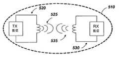
도 16a 내지 16d는 송신기와 하나 이상의 수신기들 사이에서 전력을 송신하기 위한 비컨 전력 모드를 도시한 간략화된 블록도들이다. 도 16a는, 비컨 커플링-모드 영역 (510) 에 수신 디바이스들이 존재하지 않는 경우 저전력 "비컨" 신호 (525) 를 갖는 송신기 (520) 를 도시한다. 비-제한적인 예로서, 비컨 신호 (525) 는 예를 들어, ~10 내지 ~20mW RF의 범위에 있을 수도 있다. 이러한 신호는, 충전될 디바이스가 커플링-모드 영역에 배치될 경우 그 디바이스에 초기 전력을 제공하는데 적절할 수도 있다.16A-16D are simplified block diagrams illustrating a beacon power mode for transmitting power between a transmitter and one or more receivers. 16A shows a
도 16b는 비컨 신호 (525) 를 송신하는 송신기 (520) 의 비컨 커플링-모드 영역 (510) 내에 배치된 수신 디바이스 (530) 를 도시한다. 수신 디바이스 (530) 가 온되고 송신기와의 커플링을 전개하면, 그 디바이스는 역방향 링크 커플링 (535) 을 생성할 것이고, 실제로 비컨 신호 (525) 로부터 전력을 수신하는 수신기가 된다. 이러한 부가적인 전력은 송신기의 로드 감지 회로 (216) (도 12) 에 의해 감지될 수도 있다. 그 결과, 송신기는 고전력 모드로 진입할 수도 있다.16B shows a receiving
도 16c는 고전력 커플링-모드 영역 (510') 을 초래하는 고전력 신호 (525') 를 생성하는 송신기 (520) 를 도시한다. 수신 디바이스 (530) 가 전력을 수신하고 있고 그 결과 역방향 링크 커플링 (535) 을 생성하고 있는 한, 송신기는 고전력 상태로 유지될 것이다. 단지 하나의 수신 디바이스 (530) 가 도시되어 있지만, 다수의 수신 디바이스들 (530) 이 커플링-모드 영역 (510) 에 존재할 수도 있다. 다수의 수신 디바이스 (530) 가 존재하면, 그들은, 각각의 수신 디바이스 (530) 가 매우 양호하게 커플링되는 방법에 기초하여 송신기에 의해 송신된 전력의 양을 공유할 것이다. 예를 들어, 도 8 및 9를 참조하여 상술된 바와 같이, 커플링 효율도는, 커플링-모드 영역 (510) 에 디바이스가 배치되는 위치에 의존하여 각각의 수신 디바이스 (530) 에 대해 상이할 수도 있다.16C illustrates a
도 16d는 수신 디바이스 (530) 가 비컨 커플링-모드 영역 (510) 에 존재하는 경우라도 비컨 신호 (525) 를 생성하는 송신기 (520) 를 도시한다. 이러한 상태는, 아마도 그 디바이스가 임의의 더 많은 전력을 필요로 하지 않기 때문에, 수신 디바이스 (530) 가 셧 오프되거나, 디바이스 그 자체가 클로우킹할 경우 발생할 수도 있다.16D shows a
시간-멀티플렉싱 모드에 있어서, 수신기 및 송신기는 별개의 통신 채널 (예를 들어, 블루투스, 지그비 등) 상에서 통신할 수도 있다. 별개의 통신 채널으로, 송신기는, 커플링-모드 영역 (510) 내의 수신 디바이스들의 수 및 그들 각각의 전력 요건들에 기초하여, 비컨 모드와 고전력 모드 사이에서 스위칭할 시간을 결정하거나 다수의 전력 레벨들을 생성할 수도 있다.In the time-multiplexing mode, the receiver and the transmitter may communicate on separate communication channels (e. G., Bluetooth, zigbee, etc.). In a separate communication channel, the transmitter determines the time to switch between the beacon mode and the high power mode based on the number of receiving devices in the coupling-
당업자는, 정보 및 신호들이 임의의 다양한 서로 다른 기술들 및 기법들을 사용하여 표현될 수도 있음을 이해할 것이다. 예를 들어, 상기 설명 전반에 걸쳐 참조될 수도 있는 데이터, 명령들, 커맨드들, 정보, 신호들, 비트들, 심볼들, 및 칩들은 전압들, 전류들, 전자기파들, 자기장 또는 자기입자, 광학 필드 또는 광학 입자, 또는 이들의 임의의 조합에 의해 표현될 수도 있다.Those skilled in the art will appreciate that information and signals may be represented using any of a variety of different technologies and techniques. For example, data, instructions, commands, information, signals, bits, symbols, and chips that may be referenced throughout the above description may be represented by voltages, currents, electromagnetic waves, Field or optical particle, or any combination thereof.
또한, 당업자는, 여기에 개시된 실시형태들과 관련하여 설명된 다양한 예시적인 논리 블록들, 모듈들, 회로들, 및 알고리즘 단계들이 전자 하드웨어, 컴퓨터 소프트웨어 또는 이들의 조합으로서 구현될 수도 있음을 인식할 것이다. 하드웨어와 소프트웨어의 이러한 상호교환가능성을 명확히 예시하기 위해, 다양한 예시적인 컴포넌트들, 블록들, 모듈들, 회로들 및 단계들은 그들의 기능의 관점으로 일반적으로 상술되었다. 그러한 기능이 하드웨어 또는 소프트웨어로 구현될지는, 특정 애플리케이션 및 전체 시스템에 부과된 설계 제약들에 의존한다. 당업자는 각각의 특정한 애플리케이션에 대한 다양한 방식으로 설명된 기능을 구현할 수도 있지만, 그러한 구현 결정들이 본 발명의 예시적인 실시형태들의 범위를 벗어나게 하는 것으로 해석되지는 않아야 한다.Those skilled in the art will also appreciate that the various illustrative logical blocks, modules, circuits, and algorithm steps described in connection with the embodiments disclosed herein may be implemented as electronic hardware, computer software, or combinations of both will be. To clearly illustrate this interchangeability of hardware and software, various illustrative components, blocks, modules, circuits, and steps have been described above generally in terms of their functionality. Whether such functionality is implemented as hardware or software depends upon the particular application and design constraints imposed on the overall system. Skilled artisans may implement the described functionality in varying ways for each particular application, but such implementation decisions should not be interpreted as causing a departure from the scope of the exemplary embodiments of the present invention.
여기에 개시된 실시형태들과 관련하여 설명된 다양한 예시적인 논리 블록들, 모듈들, 및 회로들은, 범용 프로세서, 디지털 신호 프로세서 (DSP), 주문형 집적 회로 (ASIC), 필드 프로그래밍가능한 게이트 어레이 (FPGA) 또는 다른 프로그래밍가능한 로직 디바이스, 이산 게이트 또는 트랜지스터 로직, 이산 하드웨어 컴포넌트들, 또는 여기에 설명된 기능들을 수행하도록 설계된 이들의 임의의 조합으로 구현 또는 수행될 수도 있다. 범용 프로세서는 마이크로프로세서일 수도 있지만, 대안적으로, 그 프로세서는 임의의 종래의 프로세서, 제어기, 마이크로제어기, 또는 상태 머신일 수도 있다. 또한, 프로세서는 컴퓨팅 디바이스들의 조합, 예를 들어, DSP와 마이크로프로세서의 조합, 복수의 마이크로프로세서들, DSP 코어와 결합된 하나 이상의 마이크로프로세서들, 또는 임의의 다른 그러한 구성으로서 구현될 수도 있다.The various illustrative logical blocks, modules, and circuits described in connection with the embodiments disclosed herein may be implemented or performed with a general purpose processor, a digital signal processor (DSP), an application specific integrated circuit (ASIC), a field programmable gate array Or other programmable logic device, discrete gate or transistor logic, discrete hardware components, or any combination thereof designed to perform the functions described herein. A general purpose processor may be a microprocessor, but in the alternative, the processor may be any conventional processor, controller, microcontroller, or state machine. A processor may also be implemented as a combination of computing devices, e.g., a combination of a DSP and a microprocessor, a plurality of microprocessors, one or more microprocessors in conjunction with a DSP core, or any other such configuration.
여기에 개시된 실시형태들과 관련하여 설명된 방법 또는 알고리즘의 단계들은 하드웨어로 직접, 프로세서에 의해 실행되는 소프트웨어 모듈, 또는 이 둘의 조합으로 구현될 수도 있다. 소프트웨어 모듈은, 랜덤 액세스 메모리 (RAM), 플래시 메모리, 판독 전용 메모리 (ROM), 전기적으로 프로그래밍가능한 ROM (EPROM), 전기적으로 소거가능한 프로그래밍가능 ROM (EEPROM), 레지스터들, 하드 디스크, 착탈형 디스크, CD-ROM, 또는 당업계에 알려진 임의의 다른 형태의 저장 매체에 상주할 수도 있다. 예시적인 저장 매체는 프로세서에 커플링되어, 그 프로세서가 저장 매체로부터 정보를 판독할 수 있고 저장 매체에 정보를 기입할 수 있게 한다. 대안적으로, 저장 매체는 프로세서에 통합될 수도 있다. 프로세서 및 저장 매체는 ASIC에 상주할 수도 있다. ASIC는 사용자 단말기에 상주할 수도 있다. 대안적으로, 프로세서 및 저장 매체는 사용자 단말기 내의 별개의 컴포넌트들로서 상주할 수도 있다.The steps of a method or algorithm described in connection with the embodiments disclosed herein may be embodied directly in hardware, in a software module executed by a processor, or in a combination of the two. A software module may reside in a memory such as a random access memory (RAM), a flash memory, a read only memory (ROM), an electrically programmable ROM (EPROM), an electrically erasable programmable ROM (EEPROM), registers, CD-ROM, or any other form of storage medium known in the art. An exemplary storage medium is coupled to the processor such that the processor can read information from and write information to the storage medium. In the alternative, the storage medium may be integral to the processor. The processor and the storage medium may reside in an ASIC. The ASIC may reside in a user terminal. Alternatively, the processor and the storage medium may reside as discrete components in a user terminal.
하나 이상의 예시적인 실시형태들에서, 설명된 기능들은 하드웨어, 소프트웨어, 펌웨어 또는 이들의 임의의 조합으로 구현될 수도 있다. 소프트웨어로 구현되면, 그 기능들은 컴퓨터-판독가능 매체 상에 저장될 수도 있거나, 컴퓨터-판독가능 매체 상의 하나 이상의 명령들 또는 코드로서 송신될 수도 있다. 컴퓨터-판독가능 매체는, 일 장소로부터 또 다른 장소로의 컴퓨터 프로그램의 전달을 용이하게 하는 임의의 매체를 포함하는 통신 매체 및 컴퓨터 저장 매체 양자를 포함한다. 저장 매체는 컴퓨터에 의해 액세스될 수 있는 임의의 이용가능한 매체일 수도 있다. 제한이 아닌 예로서, 그러한 컴퓨터-판독가능 매체는, RAM, ROM, EEPROM, CD-ROM 또는 다른 광학 디스크 저장부, 자성 디스크 저장부 또는 다른 자성 저장 디바이스들, 또는 명령들 또는 데이터 구조들의 형태로 원하는 프로그램 코드를 운반 또는 저장하는데 사용될 수 있고 컴퓨터에 이해 액세스될 수 있는 임의의 다른 매체를 포함할 수 있다. 또한, 임의의 접속은 컴퓨터-판독가능 매체로 적절히 명칭될 수도 있다. 예를 들어, 소프트웨어가 동축 케이블, 광섬유 케이블, 꼬인 쌍, 디지털 가입자 라인 (DSL), 또는 적외선, 무선, 및 마이크로파와 같은 무선 기술들을 사용하여 웹사이트, 서버, 또는 다른 원격 소스로부터 송신되면, 동축 케이블, 광섬유 케이블, 꼬인 쌍, DSL, 또는 적외선, 무선, 및 마이크로파와 같은 무선 기술들은 매체의 정의 내에 포함된다. 여기에 사용된 바와 같이, 디스크 및 disc는, 컴팩 disc (CD), 레이저 disc, 광학 disc, DVD (digital versatile disc), 플로피 디스크 및 블루-레이 disc 를 포함하며, 여기서, 디스크는 일반적으로 데이터를 자기적으로 재생하지만, disc들은 데이터를 레이저들을 이용하여 광학적으로 재생한다. 또한, 상기의 조합들은 컴퓨터-판독가능 매체의 범위 내에 포함되어야 한다.In one or more illustrative embodiments, the functions described may be implemented in hardware, software, firmware or any combination thereof. When implemented in software, the functions may be stored on a computer-readable medium or may be transmitted as one or more instructions or code on a computer-readable medium. Computer-readable media includes both computer storage media and communication media including any medium that facilitates transfer of a computer program from one place to another. The storage medium may be any available media that can be accessed by a computer. By way of example, and not limitation, such computer-readable media can be embodied in a computer-readable medium such as RAM, ROM, EEPROM, CD-ROM or other optical disk storage, magnetic disk storage or other magnetic storage devices, And any other medium that can be used to carry or store the desired program code and that can be easily accessed by a computer. In addition, any connection may be properly termed a computer-readable medium. For example, if software is transmitted from a web site, server, or other remote source using wireless technologies such as coaxial cable, fiber optic cable, twisted pair, digital subscriber line (DSL), or infrared, radio, and microwave, Wireless technologies such as cable, fiber optic cable, twisted pair, DSL, or infrared, radio, and microwave are included within the definition of medium. As used herein, discs and discs include compact discs (CDs), laser discs, optical discs, digital versatile discs (DVDs), floppy discs and Blu-ray discs, While magnetically reproducing, discs optically reproduce data using lasers. In addition, the above combinations should be included within the scope of computer-readable media.
개시된 예시적인 실시형태들의 이전 설명은 당업자가 본 발명을 수행 또는 이용할 수 있도록 제공된다. 이들 예시적인 실시형태들에 대한 다양한 변형들은 당업자에게는 용이하게 명백할 것이며, 여기에 정의된 일반적인 원리들은 본 발명의 사상 또는 범위를 벗어나지 않고도 다른 실시형태들에 적용될 수도 있다. 따라서, 본 발명은 여기에 설명된 실시형태들로 제한되도록 의도되는 것이 아니라, 여기에 개시된 신규한 특성들 및 원리들에 부합하는 최광의 범위를 허여하려는 것이다.The previous description of the disclosed exemplary embodiments is provided to enable any person skilled in the art to make or use the present invention. Various modifications to these exemplary embodiments will be readily apparent to those skilled in the art, and the generic principles defined herein may be applied to other embodiments without departing from the spirit or scope of the invention. Accordingly, the invention is not intended to be limited to the embodiments shown herein but is to be accorded the widest scope consistent with the novel features and principles herein disclosed.
Claims (27)
Translated fromKorean상기 송신 안테나에 RF 신호를 제공하도록 구성되는 증폭기; 및
상기 송신 안테나에 동작가능하게 커플링된 송신 제어기를 포함하며,
상기 송신 제어기는, 상기 영역 내에 배치된 복수의 수신 디바이스들의 각각에 대해 순환 주기 내에서 전력이 할당되는 시간을 결정하고, 상기 복수의 수신 디바이스들의 각각에 상기 전력이 할당되는 시간을 통신하도록 구성되는, 무선 전력 송신기.A transmit antenna configured to generate radiation within an area where power can be received by the receiver;
An amplifier configured to provide an RF signal to the transmit antenna; And
A transmit controller operatively coupled to the transmit antenna,
The transmitting controller is configured to determine a time for which power is allocated within a circular period for each of a plurality of receiving devices disposed in the area, and to communicate a time for which the power is allocated to each of the plurality of receiving devices. , Wireless power transmitter.
상기 송신 제어기에 동작가능하게 커플링된 무선 통신기를 더 포함하며,
상기 무선 통신기는, 상기 송신 안테나의 무선 채널과는 상이한 무선 채널을 통해 상기 복수의 수신 디바이스들과 통신하도록 구성되고,
상기 송신 제어기는 상기 무선 채널을 통해 상기 전력이 할당되는 시간을 통신하는, 무선 전력 송신기.The method of claim 1,
Further comprising a wireless communicator operatively coupled to the transmit controller,
The wireless communicator is configured to communicate with the plurality of receiving devices via a wireless channel different from the wireless channel of the transmit antenna,
And the transmission controller communicates the time over which the power is allocated over the wireless channel.
상기 송신 제어기는,
상기 증폭기가, 송신 변조 신호가 제 1 상태에 있는 경우 상기 송신 안테나에 상기 RF 신호를 인가하고, 상기 송신 변조 신호가 제 2 상태에 있는 경우 상기 송신 안테나에 DC 신호를 인가하도록, 상기 증폭기로 상기 송신 변조 신호를 보냄으로써 상기 전력이 할당되는 시간을 통신하는, 무선 전력 송신기.The method of claim 1,
The transmission controller,
The amplifier applies the RF signal to the transmit antenna when the transmit modulated signal is in the first state and the DC signal to the transmit antenna when the transmit modulated signal is in the second state; And communicate the time for which the power is allocated by sending a transmit modulated signal.
상기 송신 제어기 및 상기 증폭기에 동작가능하게 커플링된 제어기를 더 포함하고,
상기 제어기는,
동기화 부분 및 전력 송신 부분을 포함하는 순환 주기를 제공하고;
상기 증폭기가 상기 RF 신호를 상기 송신 안테나에 제공하여 상기 순환 주기의 상기 동기화 부분동안 상기 방사를 생성하도록 지시하고;
상기 영역 내에 적어도 하나의 수신기가 있는 경우, 상기 순환 주기의 상기 전력 송신 부분동안, 상기 증폭기가 상기 RF 신호를 제공하도록 지시하는 것을 계속하고; 그리고
상기 영역 내에 수신기가 없는 경우, 상기 순환 주기의 상기 전력 송신 부분동안, 상기 증폭기가 상기 RF 신호를 제공하도록 지시하는 것을 중단하도록 구성되는, 무선 전력 송신기.The method of claim 1,
Further comprising a controller operably coupled to the transmit controller and the amplifier,
The controller,
Providing a cyclic period comprising a synchronization portion and a power transmission portion;
Instruct the amplifier to provide the RF signal to the transmit antenna to generate the radiation during the synchronization portion of the cycle period;
If there is at least one receiver in the area, during the power transmission portion of the cyclic period, continuing to instruct the amplifier to provide the RF signal; And
And when there is no receiver in the area, during the power transmission portion of the cycling period, configured to stop instructing the amplifier to provide the RF signal.
상기 제어기는 또한, 상기 증폭기를 인에이블/디스에이블시킴으로써 상기 방사의 온/오프 키잉을 수행함으로써 상기 동기화 부분 동안 상기 송신기로부터 수신기로의 시리얼 커맨드를 생성하도록 구성되는, 무선 전력 송신기.The method of claim 4, wherein
The controller is further configured to generate a serial command from the transmitter to the receiver during the synchronization portion by performing on / off keying of the radiation by enabling / disabling the amplifier.
상기 증폭기 및 상기 제어기에 동작가능하게 커플링된 로드 감지 회로를 더 포함하며,
상기 로드 감지 회로는, 상기 증폭기에 의한 전력 소비에서의 변화들을 검출하고, 상기 전력 소비에서의 변화들에 기초하여 상기 제어기로의 시리얼 응답 신호를 생성하도록 구성되고,
상기 제어기는 또한, 상기 영역에서의 새로운 수신기의 존재 또는 상기 영역에서의 기존의 수신기의 상태 중 적어도 하나를 결정하기 위해 상기 시리얼 응답을 디코딩하도록 구성되는, 무선 전력 송신기.The method of claim 5, wherein
Further comprising a load sensing circuit operably coupled to the amplifier and the controller,
The load sensing circuit is configured to detect changes in power consumption by the amplifier and generate a serial response signal to the controller based on the changes in power consumption,
The controller is further configured to decode the serial response to determine at least one of a presence of a new receiver in the area or a state of an existing receiver in the area.
수신기에 의해 전력이 수신될 수 있는 영역 내에서, 송신 안테나에 의해 방사를 생성하는 단계;
상기 송신 안테나에 RF 신호를 제공하는 단계;
상기 영역 내에 배치된 복수의 수신 디바이스들의 각각에 대해 순환 주기 내에서 전력이 할당되는 시간을 결정하는 단계; 및
상기 복수의 수신 디바이스들의 각각에 상기 전력이 할당되는 시간을 통신하는 단계를 포함하는, 송신기 및 수신기 사이의 통신 방법.A method for communication between a transmitter and a receiver,
Generating radiation by a transmitting antenna in an area in which power may be received by a receiver;
Providing an RF signal to the transmit antenna;
Determining a time for which power is allocated within a circular period for each of a plurality of receiving devices disposed in the area; And
Communicating a time at which the power is allocated to each of the plurality of receiving devices.
상기 송신 안테나의 무선 채널과는 상이한 무선 채널을 통해 상기 복수의 수신 디바이스들과 통신하는 단계를 더 포함하고,
상기 시간을 통신하는 단계는, 상기 무선 채널을 통해 상기 전력이 할당되는 시간을 통신하는 단계를 포함하는, 송신기 및 수신기 사이의 통신 방법.The method of claim 7, wherein
Communicating with the plurality of receiving devices over a wireless channel different from the wireless channel of the transmit antenna,
Communicating the time comprises communicating a time over which the power is allocated over the wireless channel.
상기 시간을 통신하는 단계는, 증폭기가, 송신 변조 신호가 제 1 상태에 있는 경우 상기 송신 안테나에 상기 RF 신호를 인가하고, 상기 송신 변조 신호가 제 2 상태에 있는 경우 상기 송신 안테나에 DC 신호를 인가하도록, 상기 증폭기로 상기 송신 변조 신호를 보내는 단계를 포함하는, 송신기 및 수신기 사이의 통신 방법.The method of claim 7, wherein
The communicating the time may include an amplifier applying the RF signal to the transmit antenna when the transmit modulated signal is in the first state and applying a DC signal to the transmit antenna when the transmit modulated signal is in the second state. Sending the transmit modulated signal to the amplifier for application.
동기화 부분 및 전력 송신 부분을 포함하는 순환 주기를 제공하는 단계;
상기 RF 신호를 상기 송신 안테나에 제공하여 상기 순환 주기의 상기 동기화 부분동안 방사를 생성하는 단계;
상기 영역 내에 적어도 하나의 수신기가 있는 경우, 상기 순환 주기의 상기 전력 송신 부분동안, 상기 RF 신호를 제공하는 것을 계속하는 단계; 및
상기 영역 내에 수신기가 없는 경우, 상기 순환 주기의 상기 전력 송신 부분동안, 상기 RF 신호를 제공하는 것을 중단하는 단계를 더 포함하는, 송신기 및 수신기 사이의 통신 방법.The method of claim 7, wherein
Providing a cyclic period comprising a synchronization portion and a power transmission portion;
Providing the RF signal to the transmit antenna to generate radiation during the synchronization portion of the cycle period;
If there is at least one receiver in the area, continuing to provide the RF signal during the power transmission portion of the cycling period; And
If there is no receiver in the area, during the power transmission portion of the cycle, stopping providing the RF signal.
상기 증폭기를 인에이블/디스에이블시킴으로써 상기 방사의 온/오프 키잉을 수행함으로써 상기 동기화 부분 동안 상기 송신기로부터 수신기로의 시리얼 커맨드를 생성하는 단계를 더 포함하는, 송신기 및 수신기 사이의 통신 방법.11. The method of claim 10,
Generating a serial command from the transmitter to the receiver during the synchronization portion by performing on / off keying of the radiation by enabling / disabling the amplifier.
상기 증폭기에 의한 전력 소비에서의 변화들을 검출하고, 상기 전력 소비에서의 변화들에 기초하여 시리얼 응답 신호를 생성하는 단계; 및
상기 영역에서의 새로운 수신기의 존재 또는 상기 영역에서의 기존의 수신기의 상태 중 적어도 하나를 결정하기 위해 상기 시리얼 응답을 디코딩하는 단계를 더 포함하는, 송신기 및 수신기 사이의 통신 방법.The method of claim 11,
Detecting changes in power consumption by the amplifier and generating a serial response signal based on the changes in power consumption; And
Decoding the serial response to determine at least one of a presence of a new receiver in the area or a state of an existing receiver in the area.
수신기에 의해 전력이 수신될 수 있는 영역 내에서 방사를 생성하는 수단;
상기 생성하는 수단에 RF 신호를 제공하는 수단;
상기 영역 내에 배치된 복수의 수신 디바이스들의 각각에 대해 순환 주기 내에서 전력이 할당되는 시간을 결정하는 수단; 및
상기 복수의 수신 디바이스들의 각각에 상기 전력이 할당되는 시간을 통신하는 수단을 포함하는, 송신기 및 수신기 사이의 통신을 위한 장치.An apparatus for communication between a transmitter and a receiver,
Means for generating radiation in an area in which power may be received by a receiver;
Means for providing an RF signal to the means for generating;
Means for determining a time for which power is allocated within a circular period for each of a plurality of receiving devices disposed within the area; And
Means for communicating a time at which the power is allocated to each of the plurality of receiving devices.
상기 생성하는 수단의 무선 채널과는 상이한 무선 채널을 통해 상기 복수의 수신 디바이스들과 통신하는 수단을 더 포함하고,
상기 시간을 통신하는 수단은, 상기 무선 채널을 통해 상기 전력이 할당되는 시간을 통신하는 수단을 포함하는, 송신기 및 수신기 사이의 통신을 위한 장치.The method of claim 13,
Means for communicating with the plurality of receiving devices via a wireless channel different from the wireless channel of the generating means,
Means for communicating the time comprises means for communicating the time over which the power is allocated over the wireless channel.
상기 시간을 통신하는 수단은, 상기 제공하는 수단이, 송신 변조 신호가 제 1 상태에 있는 경우 상기 생성하는 수단에 상기 RF 신호를 인가하고, 상기 송신 변조 신호가 제 2 상태에 있는 경우 상기 생성하는 수단에 DC 신호를 인가하도록, 상기 제공하는 수단으로 상기 송신 변조 신호를 보내는 수단을 포함하는, 송신기 및 수신기 사이의 통신을 위한 장치.The method of claim 13,
The means for communicating the time is characterized in that the means for providing applies the RF signal to the generating means when the transmission modulated signal is in a first state and generates the transmission signal when the transmission modulated signal is in a second state. Means for sending the transmit modulated signal to the providing means to apply a DC signal to the means.
동기화 부분 및 전력 송신 부분을 포함하는 순환 주기를 제공하는 수단;
상기 RF 신호를 상기 생성하는 수단에 제공하여 상기 순환 주기의 상기 동기화 부분동안 상기 방사를 생성하는 수단;
상기 영역 내에 적어도 하나의 수신기가 있는 경우, 상기 순환 주기의 상기 전력 송신 부분동안, 상기 RF 신호를 제공하는 것을 계속하는 수단; 및
상기 영역 내에 수신기가 없는 경우, 상기 순환 주기의 상기 전력 송신 부분동안, 상기 RF 신호를 제공하는 것을 중단하는 수단을 더 포함하는, 송신기 및 수신기 사이의 통신을 위한 장치.The method of claim 13,
Means for providing a cyclic period comprising a synchronization portion and a power transmission portion;
Means for providing the RF signal to the means for generating the radiation during the synchronization portion of the cycle period;
Means for continuing to provide the RF signal during the power transmission portion of the cycle, if there is at least one receiver in the area; And
Means for stopping providing said RF signal during said power transmission portion of said cyclic period when there is no receiver in said area.
상기 제공하는 수단을 인에이블/디스에이블시킴으로써 상기 방사의 온/오프 키잉을 수행함으로써 상기 동기화 부분 동안 상기 장치로부터 수신기로의 시리얼 커맨드를 생성하는 수단을 더 포함하는, 송신기 및 수신기 사이의 통신을 위한 장치.17. The method of claim 16,
Means for generating a serial command from the device to the receiver during the synchronization portion by performing on / off keying of the radiation by enabling / disabling the providing means for communication between the transmitter and the receiver. Device.
상기 제공하는 수단에 의한 전력 소비에서의 변화들을 검출하고, 상기 전력 소비에서의 변화들에 기초하여 시리얼 응답 신호를 생성하는 수단; 및
상기 영역에서의 새로운 수신기의 존재 또는 상기 영역에서의 기존의 수신기의 상태 중 적어도 하나를 결정하기 위해 상기 시리얼 응답을 디코딩하는 수단을 더 포함하는, 송신기 및 수신기 사이의 통신을 위한 장치.The method of claim 17,
Means for detecting changes in power consumption by the providing means and generating a serial response signal based on the changes in power consumption; And
Means for decoding the serial response to determine at least one of a presence of a new receiver in the area or a state of an existing receiver in the area.
상기 수신 안테나에 동작가능하게 커플링되며, 상기 전자기장으로부터 제 1 전력량을 소비하는 제 1 전력 수신 상태 및 상기 전자기장으로부터 제 2 전력량을 소비하는 제 2 전력 수신 상태에서 무선 전력 수신기를 동작시키도록 구성되는 스위칭 회로; 및
상기 스위칭 회로에 동작가능하게 커플링된 제어기를 포함하며,
상기 제어기는, 상기 수신 안테나 상에서 시리얼 응답을 생성하도록 구성되고, 상기 제 1 전력 수신 상태 또는 상기 제 2 전력 수신 상태 중 어느 하나의 상태에 진입하기 위하여 상기 스위칭 회로를 제어함으로써 상기 시리얼 응답의 각각의 비트를 생성하도록 구성되는, 무선 전력 수신기.A receiving antenna configured to generate power by coupling to an electromagnetic field generated by the transmitting antenna;
Operatively coupled to the receive antenna, the wireless power receiver configured to operate in a first power receive state consuming a first amount of power from the electromagnetic field and a second power receive state consuming a second amount of power from the electromagnetic field. Switching circuits; And
A controller operatively coupled to the switching circuit,
The controller is configured to generate a serial response on the receive antenna, wherein each controller of the serial response is controlled by controlling the switching circuit to enter a state of either the first power receiving state or the second power receiving state. And configured to generate a bit.
상기 제어기에 동작가능하게 커플링된 신호 추출기를 더 포함하며,
상기 신호 추출기는, 상기 전자기장의 온/오프 키잉 변조를 검출하여, 상기 온/오프 키잉 변조에 기초하여 시리얼 커맨드를 추출하도록 구성되는, 무선 전력 수신기.The method of claim 19,
Further comprising a signal extractor operably coupled to the controller,
And the signal extractor is configured to detect on / off keying modulation of the electromagnetic field and extract a serial command based on the on / off keying modulation.
상기 수신 안테나에 동작가능하게 커플링된 정류기를 더 포함하며,
상기 정류기는 상기 전력 신호를 DC 전력 신호로 변환하고 상기 DC 전력 신호를 수신 디바이스에 공급하도록 구성되고,
상기 제어기는 또한, 시간-멀티플렉싱된 순환 주기의 동기화 부분을 검출하고, 상기 무선 전력 수신기에 할당된 상기 시간-멀티플렉싱된 순환 주기의 전력 송신 부분 동안 상기 정류기를 인에이블시키도록 구성되는, 무선 전력 수신기.The method of claim 19,
Further comprising a rectifier operably coupled to the receive antenna,
The rectifier is configured to convert the power signal into a DC power signal and to supply the DC power signal to a receiving device,
The controller is further configured to detect a synchronized portion of the time-multiplexed cyclic period and enable the rectifier during the power transmission portion of the time-multiplexed cyclic period assigned to the wireless power receiver. .
상기 전자기장으로부터 제 1 전력량을 소비하는 제 1 전력 수신 상태 및 상기 전자기장으로부터 제 2 전력량을 소비하는 제 2 전력 수신 상태에서, 스위칭 회로에 의해 동작시키는 단계; 및
상기 수신 안테나 상에서 시리얼 응답을 생성하는 단계로서, 상기 제 1 전력 수신 상태 또는 상기 제 2 전력 수신 상태 중 어느 하나의 상태에 진입하기 위하여 상기 스위칭 회로를 제어함으로써 상기 시리얼 응답의 각각의 비트를 생성하는 단계를 포함하는, 상기 시리얼 응답을 생성하는 단계를 포함하는, 송신기와 통신하기 위한 방법.Generating a power signal by coupling to an electromagnetic field generated by the transmit antenna;
Operating by a switching circuit in a first power reception state consuming a first amount of power from the electromagnetic field and in a second power reception state consuming a second amount of power from the electromagnetic field; And
Generating a serial response on the receive antenna, wherein each bit of the serial response is generated by controlling the switching circuit to enter either the first power receiving state or the second power receiving state. And generating the serial response.
온/오프 키잉 변조에 기초하여 시리얼 커맨드를 추출하기 위해 상기 전자기장의 상기 온/오프 키잉 변조를 검출하는 단계를 더 포함하는, 송신기와 통신하기 위한 방법.The method of claim 22,
Detecting the on / off keying modulation of the electromagnetic field to extract a serial command based on on / off keying modulation.
상기 전력 신호를 DC 전력 신호로 변환하고 상기 DC 전력 신호를 수신 디바이스에 공급하는 단계;
시간-멀티플렉싱된 순환 주기의 동기화 부분을 검출하는 단계; 및
상기 수신 디바이스에 할당된 상기 시간-멀티플렉싱된 순환 주기의 전력 송신 부분 동안 상기 정류기를 인에이블시키는 단계를 더 포함하는, 송신기와 통신하기 위한 방법.The method of claim 22,
Converting the power signal into a DC power signal and supplying the DC power signal to a receiving device;
Detecting a synchronized portion of a time-multiplexed cyclic period; And
Enabling the rectifier during the power transmission portion of the time-multiplexed cyclic period assigned to the receiving device.
상기 전자기장으로부터 제 1 전력량을 소비하는 제 1 전력 수신 상태 및 상기 전자기장으로부터 제 2 전력량을 소비하는 제 2 전력 수신 상태에서 동작시키는 수단; 및
수신 안테나 상에서 시리얼 응답을 생성하는 수단으로서, 상기 제 1 전력 수신 상태 또는 상기 제 2 전력 수신 상태 중 어느 하나의 상태에 진입하기 위하여 상기 동작시키는 수단을 제어함으로써 상기 시리얼 응답의 각각의 비트를 생성하는 수단을 포함하는, 상기 시리얼 응답을 생성하는 수단을 포함하는, 송신기와 통신하기 위한 장치.Means for generating a power signal by coupling to an electromagnetic field generated by a transmitting antenna;
Means for operating in a first power receive state consuming a first amount of power from the electromagnetic field and in a second power receive state consuming a second amount of power from the electromagnetic field; And
Means for generating a serial response on a receive antenna, wherein each bit of the serial response is generated by controlling the operating means to enter either the first power receiving state or the second power receiving state. Means for generating the serial response, comprising means.
온/오프 키잉 변조에 기초하여 시리얼 커맨드를 추출하기 위해 상기 전자기장의 상기 온/오프 키잉 변조를 검출하는 수단을 더 포함하는, 송신기와 통신하기 위한 장치.The method of claim 25,
Means for detecting the on / off keying modulation of the electromagnetic field to extract a serial command based on on / off keying modulation.
상기 전력 신호를 DC 전력 신호로 변환하고 상기 DC 전력 신호를 수신 디바이스에 공급하는 수단;
시간-멀티플렉싱된 순환 주기의 동기화 부분을 검출하는 수단; 및
상기 수신 디바이스에 할당된 상기 시간-멀티플렉싱된 순환 주기의 전력 송신 부분 동안 정류기를 인에이블시키는 수단을 더 포함하는, 송신기와 통신하기 위한 장치.The method of claim 25,
Means for converting the power signal into a DC power signal and supplying the DC power signal to a receiving device;
Means for detecting a synchronized portion of a time-multiplexed circular period; And
Means for enabling a rectifier during the power transmission portion of the time-multiplexed cyclic period assigned to the receiving device.
Applications Claiming Priority (23)
| Application Number | Priority Date | Filing Date | Title |
|---|---|---|---|
| US5301008P | 2008-05-13 | 2008-05-13 | |
| US5301508P | 2008-05-13 | 2008-05-13 | |
| US5301208P | 2008-05-13 | 2008-05-13 | |
| US5300408P | 2008-05-13 | 2008-05-13 | |
| US5300008P | 2008-05-13 | 2008-05-13 | |
| US5300808P | 2008-05-13 | 2008-05-13 | |
| US61/053,015 | 2008-05-13 | ||
| US61/053,000 | 2008-05-13 | ||
| US61/053,008 | 2008-05-13 | ||
| US61/053,012 | 2008-05-13 | ||
| US61/053,010 | 2008-05-13 | ||
| US61/053,004 | 2008-05-13 | ||
| US6073808P | 2008-06-11 | 2008-06-11 | |
| US6074108P | 2008-06-11 | 2008-06-11 | |
| US6073508P | 2008-06-11 | 2008-06-11 | |
| US61/060,741 | 2008-06-11 | ||
| US61/060,738 | 2008-06-11 | ||
| US61/060,735 | 2008-06-11 | ||
| US8133208P | 2008-07-16 | 2008-07-16 | |
| US61/081,332 | 2008-07-16 | ||
| US12/249,866 | 2008-10-10 | ||
| US12/249,866US9130407B2 (en) | 2008-05-13 | 2008-10-10 | Signaling charging in wireless power environment |
| PCT/US2009/043509WO2009140216A2 (en) | 2008-05-13 | 2009-05-11 | Signaling charging in wireless power environment |
Related Parent Applications (1)
| Application Number | Title | Priority Date | Filing Date |
|---|---|---|---|
| KR20107027913ADivisionKR20110009228A (en) | 2008-05-13 | 2009-05-11 | Signaling Charging in Wireless Power Environments |
Publications (2)
| Publication Number | Publication Date |
|---|---|
| KR20120109643Atrue KR20120109643A (en) | 2012-10-08 |
| KR101477368B1 KR101477368B1 (en) | 2014-12-29 |
Family
ID=41315494
Family Applications (15)
| Application Number | Title | Priority Date | Filing Date |
|---|---|---|---|
| KR1020127029396AActiveKR101256776B1 (en) | 2008-05-13 | 2009-05-11 | Transmit power control for a wireless charging system |
| KR1020127021788AActiveKR101477368B1 (en) | 2008-05-13 | 2009-05-11 | Signaling charging in wireless power environment |
| KR20107027914AActiveKR101247419B1 (en) | 2008-05-13 | 2009-05-11 | Repeaters for enhancement of wireless power transfer |
| KR20107027913ACeasedKR20110009228A (en) | 2008-05-13 | 2009-05-11 | Signaling Charging in Wireless Power Environments |
| KR20107027908ACeasedKR20110010105A (en) | 2008-05-13 | 2009-05-11 | Method and apparatus for adaptive tuning of wireless power delivery |
| KR20107027905AExpired - Fee RelatedKR101319146B1 (en) | 2008-05-13 | 2009-05-11 | Reverse link signaling via receive antenna impedance modulation |
| KR20107027909AExpired - Fee RelatedKR101243544B1 (en) | 2008-05-13 | 2009-05-11 | Wireless power transfer for appliances and equipments |
| KR20107027911AActiveKR101398367B1 (en) | 2008-05-13 | 2009-05-11 | Method and apparatus for an enlarged wireless charging area |
| KR1020107027906AExpired - Fee RelatedKR101214029B1 (en) | 2008-05-13 | 2009-05-11 | Method and apparatus with negative resistance in wireless power transfers |
| KR1020137031712AActiveKR101524966B1 (en) | 2008-05-13 | 2009-05-11 | Signaling charging in wireless power environment |
| KR1020137010141ACeasedKR20130048801A (en) | 2008-05-13 | 2009-05-11 | Method and apparatus for adaptive tuning of wireless power transfer |
| KR20137016311AActiveKR101414390B1 (en) | 2008-05-13 | 2009-05-11 | Reverse link signaling via receive antenna impedance modulation |
| KR20107027910AActiveKR101243592B1 (en) | 2008-05-13 | 2009-05-11 | Receive antenna for wireless power transfer |
| KR1020137032131AActiveKR101523873B1 (en) | 2008-05-13 | 2009-05-11 | Reverse link signaling via receive antenna impedance modulation |
| KR20107027912AActiveKR101256723B1 (en) | 2008-05-13 | 2009-05-11 | Transmit power control for a wireless charging system |
Family Applications Before (1)
| Application Number | Title | Priority Date | Filing Date |
|---|---|---|---|
| KR1020127029396AActiveKR101256776B1 (en) | 2008-05-13 | 2009-05-11 | Transmit power control for a wireless charging system |
Family Applications After (13)
| Application Number | Title | Priority Date | Filing Date |
|---|---|---|---|
| KR20107027914AActiveKR101247419B1 (en) | 2008-05-13 | 2009-05-11 | Repeaters for enhancement of wireless power transfer |
| KR20107027913ACeasedKR20110009228A (en) | 2008-05-13 | 2009-05-11 | Signaling Charging in Wireless Power Environments |
| KR20107027908ACeasedKR20110010105A (en) | 2008-05-13 | 2009-05-11 | Method and apparatus for adaptive tuning of wireless power delivery |
| KR20107027905AExpired - Fee RelatedKR101319146B1 (en) | 2008-05-13 | 2009-05-11 | Reverse link signaling via receive antenna impedance modulation |
| KR20107027909AExpired - Fee RelatedKR101243544B1 (en) | 2008-05-13 | 2009-05-11 | Wireless power transfer for appliances and equipments |
| KR20107027911AActiveKR101398367B1 (en) | 2008-05-13 | 2009-05-11 | Method and apparatus for an enlarged wireless charging area |
| KR1020107027906AExpired - Fee RelatedKR101214029B1 (en) | 2008-05-13 | 2009-05-11 | Method and apparatus with negative resistance in wireless power transfers |
| KR1020137031712AActiveKR101524966B1 (en) | 2008-05-13 | 2009-05-11 | Signaling charging in wireless power environment |
| KR1020137010141ACeasedKR20130048801A (en) | 2008-05-13 | 2009-05-11 | Method and apparatus for adaptive tuning of wireless power transfer |
| KR20137016311AActiveKR101414390B1 (en) | 2008-05-13 | 2009-05-11 | Reverse link signaling via receive antenna impedance modulation |
| KR20107027910AActiveKR101243592B1 (en) | 2008-05-13 | 2009-05-11 | Receive antenna for wireless power transfer |
| KR1020137032131AActiveKR101523873B1 (en) | 2008-05-13 | 2009-05-11 | Reverse link signaling via receive antenna impedance modulation |
| KR20107027912AActiveKR101256723B1 (en) | 2008-05-13 | 2009-05-11 | Transmit power control for a wireless charging system |
Country Status (7)
| Country | Link |
|---|---|
| US (14) | US20090284369A1 (en) |
| EP (9) | EP2294710B1 (en) |
| JP (18) | JP5507547B2 (en) |
| KR (15) | KR101256776B1 (en) |
| CN (14) | CN102027684B (en) |
| TW (9) | TW201004089A (en) |
| WO (9) | WO2009140223A1 (en) |
Cited By (1)
| Publication number | Priority date | Publication date | Assignee | Title |
|---|---|---|---|---|
| US9698630B2 (en) | 2013-08-01 | 2017-07-04 | Samsung Electronics Co., Ltd. | Method and apparatus for wireless energy reception using hybrid synchronization |
Families Citing this family (1110)
| Publication number | Priority date | Publication date | Assignee | Title |
|---|---|---|---|---|
| US7355470B2 (en) | 2006-04-24 | 2008-04-08 | Parkervision, Inc. | Systems and methods of RF power transmission, modulation, and amplification, including embodiments for amplifier class transitioning |
| US7327803B2 (en) | 2004-10-22 | 2008-02-05 | Parkervision, Inc. | Systems and methods for vector power amplification |
| CN101860089B (en) | 2005-07-12 | 2013-02-06 | 麻省理工学院 | wireless non-radiative energy transfer |
| US7825543B2 (en) | 2005-07-12 | 2010-11-02 | Massachusetts Institute Of Technology | Wireless energy transfer |
| US8334722B2 (en) | 2007-06-28 | 2012-12-18 | Parkervision, Inc. | Systems and methods of RF power transmission, modulation and amplification |
| US20130078934A1 (en) | 2011-04-08 | 2013-03-28 | Gregory Rawlins | Systems and Methods of RF Power Transmission, Modulation, and Amplification |
| US9106316B2 (en) | 2005-10-24 | 2015-08-11 | Parkervision, Inc. | Systems and methods of RF power transmission, modulation, and amplification |
| US7911272B2 (en) | 2007-06-19 | 2011-03-22 | Parkervision, Inc. | Systems and methods of RF power transmission, modulation, and amplification, including blended control embodiments |
| US7952322B2 (en) | 2006-01-31 | 2011-05-31 | Mojo Mobility, Inc. | Inductive power source and charging system |
| US8169185B2 (en) | 2006-01-31 | 2012-05-01 | Mojo Mobility, Inc. | System and method for inductive charging of portable devices |
| US11201500B2 (en) | 2006-01-31 | 2021-12-14 | Mojo Mobility, Inc. | Efficiencies and flexibilities in inductive (wireless) charging |
| US8031804B2 (en) | 2006-04-24 | 2011-10-04 | Parkervision, Inc. | Systems and methods of RF tower transmission, modulation, and amplification, including embodiments for compensating for waveform distortion |
| US9064198B2 (en) | 2006-04-26 | 2015-06-23 | Murata Manufacturing Co., Ltd. | Electromagnetic-coupling-module-attached article |
| US11329511B2 (en) | 2006-06-01 | 2022-05-10 | Mojo Mobility Inc. | Power source, charging system, and inductive receiver for mobile devices |
| US7948208B2 (en) | 2006-06-01 | 2011-05-24 | Mojo Mobility, Inc. | Power source, charging system, and inductive receiver for mobile devices |
| US9143009B2 (en)* | 2007-02-01 | 2015-09-22 | The Chamberlain Group, Inc. | Method and apparatus to facilitate providing power to remote peripheral devices for use with a movable barrier operator system |
| US8235299B2 (en) | 2007-07-04 | 2012-08-07 | Murata Manufacturing Co., Ltd. | Wireless IC device and component for wireless IC device |
| WO2008144017A1 (en) | 2007-05-18 | 2008-11-27 | Parkervision, Inc. | Systems and methods of rf power transmission, modulation, and amplification |
| US8115448B2 (en) | 2007-06-01 | 2012-02-14 | Michael Sasha John | Systems and methods for wireless power |
| US9421388B2 (en) | 2007-06-01 | 2016-08-23 | Witricity Corporation | Power generation for implantable devices |
| US11264841B2 (en) | 2007-06-14 | 2022-03-01 | Ossia Inc. | Wireless power transmission system |
| US8446248B2 (en)* | 2007-06-14 | 2013-05-21 | Omnilectric, Inc. | Wireless power transmission system |
| US8159364B2 (en) | 2007-06-14 | 2012-04-17 | Omnilectric, Inc. | Wireless power transmission system |
| WO2008156800A1 (en) | 2007-06-19 | 2008-12-24 | Parkervision, Inc. | Combiner-less multiple input single output (miso) amplification with blended control |
| CN102915462B (en) | 2007-07-18 | 2017-03-01 | 株式会社村田制作所 | Wireless IC device |
| WO2009036406A1 (en)* | 2007-09-13 | 2009-03-19 | Nigel Power, Llc | Antennas for wireless power applications |
| FI120853B (en)* | 2007-09-18 | 2010-03-31 | Powerkiss Oy | Energy transfer device and method |
| KR101502248B1 (en)* | 2007-09-19 | 2015-03-12 | 퀄컴 인코포레이티드 | Maximizing power yield from wireless power magnetic resonators |
| JP5346028B2 (en)* | 2007-09-28 | 2013-11-20 | アクセス ビジネス グループ インターナショナル リミテッド ライアビリティ カンパニー | Multiphase induction power supply system |
| US8610310B2 (en)* | 2008-02-25 | 2013-12-17 | Tivo Inc. | Wireless ethernet system |
| US8344552B2 (en)* | 2008-02-27 | 2013-01-01 | Qualcomm Incorporated | Antennas and their coupling characteristics for wireless power transfer via magnetic coupling |
| EP2251934B1 (en)* | 2008-03-03 | 2018-05-02 | Murata Manufacturing Co. Ltd. | Wireless ic device and wireless communication system |
| US8855554B2 (en) | 2008-03-05 | 2014-10-07 | Qualcomm Incorporated | Packaging and details of a wireless power device |
| US8421267B2 (en)* | 2008-03-10 | 2013-04-16 | Qualcomm, Incorporated | Packaging and details of a wireless power device |
| JP4572949B2 (en)* | 2008-04-08 | 2010-11-04 | ソニー株式会社 | Wireless communication apparatus, wireless communication system, wireless communication method, and program |
| EP2277252A4 (en) | 2008-04-21 | 2017-04-26 | Qualcomm Incorporated | Short range efficient wireless power transfer |
| JP4544338B2 (en)* | 2008-04-28 | 2010-09-15 | ソニー株式会社 | Power transmission device, power reception device, power transmission method, program, and power transmission system |
| US20110050164A1 (en) | 2008-05-07 | 2011-03-03 | Afshin Partovi | System and methods for inductive charging, and improvements and uses thereof |
| US20090284369A1 (en) | 2008-05-13 | 2009-11-19 | Qualcomm Incorporated | Transmit power control for a wireless charging system |
| US8878393B2 (en)* | 2008-05-13 | 2014-11-04 | Qualcomm Incorporated | Wireless power transfer for vehicles |
| CN102099958B (en) | 2008-05-14 | 2013-12-25 | 麻省理工学院 | Wireless power transfer including interference enhancement |
| US9024581B2 (en) | 2008-05-21 | 2015-05-05 | James W. McGinley | Charger plug with improved package |
| EP2284949B1 (en) | 2008-05-21 | 2016-08-03 | Murata Manufacturing Co. Ltd. | Wireless ic device |
| WO2009145007A1 (en) | 2008-05-26 | 2009-12-03 | 株式会社村田製作所 | Wireless ic device system and method for authenticating wireless ic device |
| US9124113B2 (en)* | 2008-07-07 | 2015-09-01 | Powerbyproxi Limited | Inductively coupled power receiver and method of operation |
| US8111042B2 (en)* | 2008-08-05 | 2012-02-07 | Broadcom Corporation | Integrated wireless resonant power charging and communication channel |
| US20100034238A1 (en)* | 2008-08-05 | 2010-02-11 | Broadcom Corporation | Spread spectrum wireless resonant power delivery |
| US9473209B2 (en)* | 2008-08-20 | 2016-10-18 | Intel Corporation | Wireless power transfer apparatus and method thereof |
| EP2329585B1 (en)* | 2008-09-11 | 2021-04-21 | Auckland UniServices Limited | Inductively coupled ac power transfer |
| US8232793B2 (en)* | 2008-09-12 | 2012-07-31 | University Of Florida Research Foundation, Inc. | Method and apparatus of load detection for a planar wireless power system |
| US8421274B2 (en)* | 2008-09-12 | 2013-04-16 | University Of Pittsburgh-Of The Commonwealth System Of Higher Education | Wireless energy transfer system |
| US7808277B2 (en)* | 2008-09-18 | 2010-10-05 | Hewlett-Packard Development Company, L.P. | Bidirectional signal separation module for a bus converter |
| EP2342797A2 (en)* | 2008-09-23 | 2011-07-13 | Powermat Ltd | Combined antenna and inductive power receiver |
| US9318922B2 (en) | 2008-09-27 | 2016-04-19 | Witricity Corporation | Mechanically removable wireless power vehicle seat assembly |
| US8723366B2 (en) | 2008-09-27 | 2014-05-13 | Witricity Corporation | Wireless energy transfer resonator enclosures |
| US9544683B2 (en) | 2008-09-27 | 2017-01-10 | Witricity Corporation | Wirelessly powered audio devices |
| US9601266B2 (en) | 2008-09-27 | 2017-03-21 | Witricity Corporation | Multiple connected resonators with a single electronic circuit |
| US8587153B2 (en) | 2008-09-27 | 2013-11-19 | Witricity Corporation | Wireless energy transfer using high Q resonators for lighting applications |
| US8598743B2 (en) | 2008-09-27 | 2013-12-03 | Witricity Corporation | Resonator arrays for wireless energy transfer |
| US8471410B2 (en) | 2008-09-27 | 2013-06-25 | Witricity Corporation | Wireless energy transfer over distance using field shaping to improve the coupling factor |
| US8400017B2 (en) | 2008-09-27 | 2013-03-19 | Witricity Corporation | Wireless energy transfer for computer peripheral applications |
| US9160203B2 (en) | 2008-09-27 | 2015-10-13 | Witricity Corporation | Wireless powered television |
| US8907531B2 (en) | 2008-09-27 | 2014-12-09 | Witricity Corporation | Wireless energy transfer with variable size resonators for medical applications |
| US8901779B2 (en) | 2008-09-27 | 2014-12-02 | Witricity Corporation | Wireless energy transfer with resonator arrays for medical applications |
| US8901778B2 (en) | 2008-09-27 | 2014-12-02 | Witricity Corporation | Wireless energy transfer with variable size resonators for implanted medical devices |
| US9515494B2 (en) | 2008-09-27 | 2016-12-06 | Witricity Corporation | Wireless power system including impedance matching network |
| US20120112538A1 (en)* | 2008-09-27 | 2012-05-10 | Kesler Morris P | Wireless energy transfer for vehicle applications |
| US8324759B2 (en) | 2008-09-27 | 2012-12-04 | Witricity Corporation | Wireless energy transfer using magnetic materials to shape field and reduce loss |
| US8461722B2 (en) | 2008-09-27 | 2013-06-11 | Witricity Corporation | Wireless energy transfer using conducting surfaces to shape field and improve K |
| US9246336B2 (en) | 2008-09-27 | 2016-01-26 | Witricity Corporation | Resonator optimizations for wireless energy transfer |
| US9093853B2 (en) | 2008-09-27 | 2015-07-28 | Witricity Corporation | Flexible resonator attachment |
| US8643326B2 (en) | 2008-09-27 | 2014-02-04 | Witricity Corporation | Tunable wireless energy transfer systems |
| US8629578B2 (en) | 2008-09-27 | 2014-01-14 | Witricity Corporation | Wireless energy transfer systems |
| US20120235566A1 (en)* | 2008-09-27 | 2012-09-20 | Aristeidis Karalis | Tunable wireless energy transfer for lighting applications |
| EP3179640A1 (en) | 2008-09-27 | 2017-06-14 | WiTricity Corporation | Wireless energy transfer systems |
| US9105959B2 (en) | 2008-09-27 | 2015-08-11 | Witricity Corporation | Resonator enclosure |
| US9184595B2 (en) | 2008-09-27 | 2015-11-10 | Witricity Corporation | Wireless energy transfer in lossy environments |
| US8912687B2 (en) | 2008-09-27 | 2014-12-16 | Witricity Corporation | Secure wireless energy transfer for vehicle applications |
| US8692410B2 (en) | 2008-09-27 | 2014-04-08 | Witricity Corporation | Wireless energy transfer with frequency hopping |
| US8461720B2 (en) | 2008-09-27 | 2013-06-11 | Witricity Corporation | Wireless energy transfer using conducting surfaces to shape fields and reduce loss |
| US8304935B2 (en) | 2008-09-27 | 2012-11-06 | Witricity Corporation | Wireless energy transfer using field shaping to reduce loss |
| US8937408B2 (en) | 2008-09-27 | 2015-01-20 | Witricity Corporation | Wireless energy transfer for medical applications |
| US8963488B2 (en) | 2008-09-27 | 2015-02-24 | Witricity Corporation | Position insensitive wireless charging |
| US20120091794A1 (en)* | 2008-09-27 | 2012-04-19 | Campanella Andrew J | Wirelessly powered laptop and desktop environment |
| US8487480B1 (en) | 2008-09-27 | 2013-07-16 | Witricity Corporation | Wireless energy transfer resonator kit |
| US8476788B2 (en) | 2008-09-27 | 2013-07-02 | Witricity Corporation | Wireless energy transfer with high-Q resonators using field shaping to improve K |
| US9601261B2 (en) | 2008-09-27 | 2017-03-21 | Witricity Corporation | Wireless energy transfer using repeater resonators |
| US9601270B2 (en) | 2008-09-27 | 2017-03-21 | Witricity Corporation | Low AC resistance conductor designs |
| US8686598B2 (en) | 2008-09-27 | 2014-04-01 | Witricity Corporation | Wireless energy transfer for supplying power and heat to a device |
| US8410636B2 (en) | 2008-09-27 | 2013-04-02 | Witricity Corporation | Low AC resistance conductor designs |
| US9396867B2 (en) | 2008-09-27 | 2016-07-19 | Witricity Corporation | Integrated resonator-shield structures |
| US9065423B2 (en) | 2008-09-27 | 2015-06-23 | Witricity Corporation | Wireless energy distribution system |
| US8552592B2 (en) | 2008-09-27 | 2013-10-08 | Witricity Corporation | Wireless energy transfer with feedback control for lighting applications |
| US8947186B2 (en) | 2008-09-27 | 2015-02-03 | Witricity Corporation | Wireless energy transfer resonator thermal management |
| US8461721B2 (en) | 2008-09-27 | 2013-06-11 | Witricity Corporation | Wireless energy transfer using object positioning for low loss |
| US8946938B2 (en) | 2008-09-27 | 2015-02-03 | Witricity Corporation | Safety systems for wireless energy transfer in vehicle applications |
| US8482158B2 (en) | 2008-09-27 | 2013-07-09 | Witricity Corporation | Wireless energy transfer using variable size resonators and system monitoring |
| US8569914B2 (en) | 2008-09-27 | 2013-10-29 | Witricity Corporation | Wireless energy transfer using object positioning for improved k |
| US8922066B2 (en) | 2008-09-27 | 2014-12-30 | Witricity Corporation | Wireless energy transfer with multi resonator arrays for vehicle applications |
| US8957549B2 (en) | 2008-09-27 | 2015-02-17 | Witricity Corporation | Tunable wireless energy transfer for in-vehicle applications |
| US9106203B2 (en) | 2008-09-27 | 2015-08-11 | Witricity Corporation | Secure wireless energy transfer in medical applications |
| US8441154B2 (en) | 2008-09-27 | 2013-05-14 | Witricity Corporation | Multi-resonator wireless energy transfer for exterior lighting |
| US8587155B2 (en) | 2008-09-27 | 2013-11-19 | Witricity Corporation | Wireless energy transfer using repeater resonators |
| US8928276B2 (en) | 2008-09-27 | 2015-01-06 | Witricity Corporation | Integrated repeaters for cell phone applications |
| US8933594B2 (en) | 2008-09-27 | 2015-01-13 | Witricity Corporation | Wireless energy transfer for vehicles |
| US8466583B2 (en) | 2008-09-27 | 2013-06-18 | Witricity Corporation | Tunable wireless energy transfer for outdoor lighting applications |
| US8692412B2 (en) | 2008-09-27 | 2014-04-08 | Witricity Corporation | Temperature compensation in a wireless transfer system |
| US8772973B2 (en) | 2008-09-27 | 2014-07-08 | Witricity Corporation | Integrated resonator-shield structures |
| US9744858B2 (en) | 2008-09-27 | 2017-08-29 | Witricity Corporation | System for wireless energy distribution in a vehicle |
| US9035499B2 (en) | 2008-09-27 | 2015-05-19 | Witricity Corporation | Wireless energy transfer for photovoltaic panels |
| US8497601B2 (en) | 2008-09-27 | 2013-07-30 | Witricity Corporation | Wireless energy transfer converters |
| US8669676B2 (en) | 2008-09-27 | 2014-03-11 | Witricity Corporation | Wireless energy transfer across variable distances using field shaping with magnetic materials to improve the coupling factor |
| US9577436B2 (en) | 2008-09-27 | 2017-02-21 | Witricity Corporation | Wireless energy transfer for implantable devices |
| US8362651B2 (en) | 2008-10-01 | 2013-01-29 | Massachusetts Institute Of Technology | Efficient near-field wireless energy transfer using adiabatic system variations |
| US8446046B2 (en) | 2008-10-03 | 2013-05-21 | Access Business Group International Llc | Power system |
| JP5287863B2 (en) | 2008-10-09 | 2013-09-11 | トヨタ自動車株式会社 | Non-contact power receiving apparatus and vehicle equipped with the same |
| US20100093412A1 (en)* | 2008-10-09 | 2010-04-15 | Inside Contactless | Protective envelope for a handheld electronic device |
| US8214003B2 (en)* | 2009-03-13 | 2012-07-03 | Pong Research Corporation | RF radiation redirection away from portable communication device user |
| US9172134B2 (en) | 2008-11-06 | 2015-10-27 | Antenna79, Inc. | Protective cover for a wireless device |
| CA2754116A1 (en) | 2008-11-06 | 2010-05-14 | Alfred Y. Wong | Radiation redirecting external case for portable communication device and antenna embedded in battery of portable communication device |
| JP4605318B2 (en) | 2008-11-17 | 2011-01-05 | 株式会社村田製作所 | Antenna and wireless IC device |
| US8810194B2 (en)* | 2008-11-20 | 2014-08-19 | Qualcomm Incorporated | Retrofitting wireless power and near-field communication in electronic devices |
| JP5244578B2 (en)* | 2008-12-24 | 2013-07-24 | 株式会社日立製作所 | Non-contact power transmission system |
| AU2010203795A1 (en) | 2009-01-06 | 2011-07-14 | Access Business Group International Llc | Wireless charging system with device power compliance |
| CN103500873B (en) | 2009-01-09 | 2016-08-31 | 株式会社村田制作所 | Wireless ic device and wireless ic module |
| US8497658B2 (en)* | 2009-01-22 | 2013-07-30 | Qualcomm Incorporated | Adaptive power control for wireless charging of devices |
| US9257865B2 (en)* | 2009-01-22 | 2016-02-09 | Techtronic Power Tools Technology Limited | Wireless power distribution system and method |
| US9136914B2 (en)* | 2009-01-22 | 2015-09-15 | Qualcomm Incorporated | Impedance change detection in wireless power transmission |
| EP2385580B1 (en) | 2009-01-30 | 2014-04-09 | Murata Manufacturing Co., Ltd. | Antenna and wireless ic device |
| US20100201310A1 (en)* | 2009-02-06 | 2010-08-12 | Broadcom Corporation | Wireless power transfer system |
| US8427330B2 (en)* | 2009-02-06 | 2013-04-23 | Broadcom Corporation | Efficiency indicator for increasing efficiency of wireless power transfer |
| US8427100B2 (en)* | 2009-02-06 | 2013-04-23 | Broadcom Corporation | Increasing efficiency of wireless power transfer |
| US20100201312A1 (en) | 2009-02-10 | 2010-08-12 | Qualcomm Incorporated | Wireless power transfer for portable enclosures |
| US20100201311A1 (en)* | 2009-02-10 | 2010-08-12 | Qualcomm Incorporated | Wireless charging with separate process |
| US20100201201A1 (en)* | 2009-02-10 | 2010-08-12 | Qualcomm Incorporated | Wireless power transfer in public places |
| US9312924B2 (en) | 2009-02-10 | 2016-04-12 | Qualcomm Incorporated | Systems and methods relating to multi-dimensional wireless charging |
| US8854224B2 (en) | 2009-02-10 | 2014-10-07 | Qualcomm Incorporated | Conveying device information relating to wireless charging |
| WO2010093942A1 (en)* | 2009-02-12 | 2010-08-19 | Gigle Networks Inc. | External ac-dc coupling for communication interfaces |
| US9407327B2 (en)* | 2009-02-13 | 2016-08-02 | Qualcomm Incorporated | Wireless power for chargeable and charging devices |
| WO2010097725A1 (en)* | 2009-02-27 | 2010-09-02 | Koninklijke Philips Electronics N.V. | Methods, transmission devices and transmission control system for transmitting power wirelessly |
| JP5365276B2 (en)* | 2009-03-17 | 2013-12-11 | ソニー株式会社 | Power transmission system and power output device |
| US8803474B2 (en)* | 2009-03-25 | 2014-08-12 | Qualcomm Incorporated | Optimization of wireless power devices |
| US8686684B2 (en)* | 2009-03-27 | 2014-04-01 | Microsoft Corporation | Magnetic inductive charging with low far fields |
| US9692485B1 (en) | 2009-03-31 | 2017-06-27 | Ronald C. Krosky | Wireless energy reception management |
| US8536736B2 (en)* | 2009-04-03 | 2013-09-17 | International Business Machines Corporation | Wireless power infrastructure |
| US8970180B2 (en)* | 2009-04-07 | 2015-03-03 | Qualcomm Incorporated | Wireless power transmission scheduling |
| TWI680928B (en) | 2009-04-10 | 2020-01-01 | 美商辛波提克有限責任公司 | Vertical lift system and method for transferring uncontained case unit to and from a multilevel storage structure |
| JP5510450B2 (en) | 2009-04-14 | 2014-06-04 | 株式会社村田製作所 | Wireless IC device |
| EP2568534A3 (en) | 2009-04-21 | 2014-05-14 | Murata Manufacturing Co., Ltd. | Antenna devie and method of setting resonant frequency of antenna device |
| JP5340017B2 (en)* | 2009-04-28 | 2013-11-13 | 三洋電機株式会社 | Built-in battery and charging stand |
| US20100280568A1 (en)* | 2009-04-30 | 2010-11-04 | Cherik Bulkes | Implantable High Efficiency Energy Transfer Module With Near-Field Inductive Coupling |
| WO2010132578A1 (en) | 2009-05-12 | 2010-11-18 | Kimball International, Inc. | Furniture with wireless power |
| US9124308B2 (en) | 2009-05-12 | 2015-09-01 | Kimball International, Inc. | Furniture with wireless power |
| US8232925B2 (en) | 2009-05-29 | 2012-07-31 | Intel Mobile Communications GmbH | Impedance tuning of transmitting and receiving antennas |
| US20120062040A1 (en)* | 2009-06-04 | 2012-03-15 | Shunichi Kaeriyama | Semiconductor device and signal transmission method |
| US8588686B2 (en) | 2009-06-09 | 2013-11-19 | Broadcom Corporation | Method and system for remote power distribution and networking for passive devices |
| US8295788B2 (en)* | 2009-06-09 | 2012-10-23 | Broadcom Corporation | Method and system for an N-phase transmitter utilizing a leaky wave antenna |
| US8320856B2 (en)* | 2009-06-09 | 2012-11-27 | Broadcom Corporation | Method and system for a leaky wave antenna as a load on a power amplifier |
| US8508422B2 (en)* | 2009-06-09 | 2013-08-13 | Broadcom Corporation | Method and system for converting RF power to DC power utilizing a leaky wave antenna |
| US9634737B2 (en)* | 2009-06-10 | 2017-04-25 | The Regents Of The University Of California | Periodic near field directors (PNFD) for short-range milli-meter-wave-wireless-interconnect (M2W2-interconnect) |
| JP2011030404A (en)* | 2009-06-22 | 2011-02-10 | Felica Networks Inc | Information processing apparatus, program, and information processing system |
| JP5499534B2 (en)* | 2009-07-07 | 2014-05-21 | ソニー株式会社 | Non-contact power receiving apparatus, power receiving method in non-contact power receiving apparatus, and non-contact power feeding system |
| US8655272B2 (en)* | 2009-07-07 | 2014-02-18 | Nokia Corporation | Wireless charging coil filtering |
| RU2548367C2 (en)* | 2009-07-13 | 2015-04-20 | Конинклейке Филипс Электроникс Н.В. | Energy inductive transmission |
| US9318897B2 (en)* | 2009-07-21 | 2016-04-19 | Texas Instruments Incorporated | Reducing corruption of communication in a wireless power transmission system |
| JP5434330B2 (en)* | 2009-07-22 | 2014-03-05 | ソニー株式会社 | Power receiving device, power transmission system, charging device, and power transmission method |
| US8922329B2 (en)* | 2009-07-23 | 2014-12-30 | Qualcomm Incorporated | Battery charging to extend battery life and improve efficiency |
| US9312728B2 (en)* | 2009-08-24 | 2016-04-12 | Access Business Group International Llc | Physical and virtual identification in a wireless power network |
| US8374545B2 (en)* | 2009-09-02 | 2013-02-12 | Qualcomm Incorporated | De-tuning in wireless power reception |
| US20110057606A1 (en)* | 2009-09-04 | 2011-03-10 | Nokia Corpation | Safety feature for wireless charger |
| GB2473257B (en)* | 2009-09-07 | 2016-11-02 | Broadcom Innovision Ltd | NFC communicators and NFC communications enabled devices |
| US20110062790A1 (en)* | 2009-09-11 | 2011-03-17 | Ammak Kouki | System for wirelessly powering three-dimension glasses and wirelessly powered 3d glasses |
| US8823219B2 (en)* | 2009-09-14 | 2014-09-02 | Qualcomm Incorporated | Headset for receiving wireless power |
| WO2011036702A1 (en)* | 2009-09-24 | 2011-03-31 | 株式会社 東芝 | Wireless power transmission system |
| US20150255994A1 (en)* | 2009-09-25 | 2015-09-10 | Witricity Corporation | Safety systems for wireless energy transfer in vehicle applications |
| JP5201270B2 (en) | 2009-09-30 | 2013-06-05 | 株式会社村田製作所 | Circuit board and manufacturing method thereof |
| JP5304580B2 (en) | 2009-10-02 | 2013-10-02 | 株式会社村田製作所 | Wireless IC device |
| KR101059657B1 (en)* | 2009-10-07 | 2011-08-25 | 삼성전기주식회사 | Wireless power transceiver and method |
| WO2011042974A1 (en)* | 2009-10-08 | 2011-04-14 | 株式会社日立製作所 | Wireless power transmission system and wireless power transmission apparatus |
| JP5327334B2 (en) | 2009-11-04 | 2013-10-30 | 株式会社村田製作所 | Communication terminal and information processing system |
| JP5459058B2 (en)* | 2009-11-09 | 2014-04-02 | 株式会社豊田自動織機 | Resonant contactless power transmission device |
| WO2011062827A2 (en)* | 2009-11-17 | 2011-05-26 | Apple Inc. | Wireless power utilization in a local computing environment |
| US8427101B2 (en)* | 2009-11-18 | 2013-04-23 | Nokia Corporation | Wireless energy repeater |
| US8559873B2 (en)* | 2009-11-20 | 2013-10-15 | Qualcomm Incorporated | Forward link signaling within a wireless power system |
| CN104617374B (en) | 2009-11-20 | 2018-04-06 | 株式会社村田制作所 | Mobile communication terminal |
| KR101730824B1 (en)* | 2009-11-30 | 2017-04-27 | 삼성전자주식회사 | Wireless power transceiver and wireless power system |
| US8525370B2 (en)* | 2009-11-30 | 2013-09-03 | Broadcom Corporation | Wireless power circuit board and assembly |
| JP5515701B2 (en)* | 2009-12-04 | 2014-06-11 | ソニー株式会社 | Power transmission device, power reception device, and power transmission control method |
| KR20110067612A (en)* | 2009-12-14 | 2011-06-22 | 삼성전자주식회사 | Resonant power generator |
| US11732527B2 (en) | 2009-12-22 | 2023-08-22 | View, Inc. | Wirelessly powered and powering electrochromic windows |
| US20130271813A1 (en) | 2012-04-17 | 2013-10-17 | View, Inc. | Controller for optically-switchable windows |
| US11630366B2 (en) | 2009-12-22 | 2023-04-18 | View, Inc. | Window antennas for emitting radio frequency signals |
| KR101702914B1 (en)* | 2009-12-29 | 2017-02-06 | 삼성전자주식회사 | Reflection power management apparatus |
| US7944279B1 (en)* | 2009-12-31 | 2011-05-17 | Nxp B.V. | Charge pump stage of radio-frequency identification transponder |
| CA2785181C (en)* | 2010-01-07 | 2018-01-02 | Voxx International Corporation | Method and apparatus for harvesting energy |
| JP2011142748A (en)* | 2010-01-07 | 2011-07-21 | Sony Corp | Wireless power supply system |
| US9178363B2 (en)* | 2010-01-26 | 2015-11-03 | Broadcom Corporation | Smart powering and pairing system and related method |
| JP5463932B2 (en)* | 2010-01-26 | 2014-04-09 | ソニー株式会社 | Information processing apparatus, information processing method, and information processing system |
| US9153995B2 (en) | 2010-01-26 | 2015-10-06 | Broadcom Corporation | Smart power delivery system and related method |
| TW201126859A (en)* | 2010-01-27 | 2011-08-01 | U Way Corp | Non-resonance wireless powering system and multipoint wireless powering method |
| JP5727146B2 (en)* | 2010-02-05 | 2015-06-03 | 日本無線株式会社 | Radar antenna device, radar antenna drive unit, and ship radar antenna power supply device |
| JP5526833B2 (en)* | 2010-02-05 | 2014-06-18 | ソニー株式会社 | Wireless power transmission device |
| GB2490074B (en)* | 2010-02-08 | 2014-02-19 | Access Business Group Int Llc | Input parasitic metal detection |
| JP5211088B2 (en)* | 2010-02-12 | 2013-06-12 | トヨタ自動車株式会社 | Power feeding device and vehicle power feeding system |
| US20110198937A1 (en)* | 2010-02-15 | 2011-08-18 | Qualcomm Incorporated | Impedance neutral wireless power receivers |
| KR101104513B1 (en)* | 2010-02-16 | 2012-01-12 | 서울대학교산학협력단 | Multiple Wireless Power Transmission Method and System Using Time Division Method |
| US8878394B2 (en)* | 2010-02-25 | 2014-11-04 | Qualcomm Incorporated | Wireless power receiver |
| TWM386699U (en)* | 2010-03-02 | 2010-08-11 | Fu Da Tong Technology Co Ltd | Actuation structure of wireless control device |
| US20110217926A1 (en)* | 2010-03-03 | 2011-09-08 | Qualcomm Incorporated | Reverse link signaling via impedance modulation |
| WO2011108340A1 (en) | 2010-03-03 | 2011-09-09 | 株式会社村田製作所 | Wireless communication module and wireless communication device |
| US9107684B2 (en)* | 2010-03-05 | 2015-08-18 | Covidien Lp | System and method for transferring power to intrabody instruments |
| KR20110102758A (en)* | 2010-03-11 | 2011-09-19 | 삼성전자주식회사 | 3D glasses, charging cradles, 3D display devices and 3D glasses wireless charging system |
| CN102576940B (en) | 2010-03-12 | 2016-05-04 | 株式会社村田制作所 | Wireless communication devices and metal article processed |
| JP5370581B2 (en) | 2010-03-24 | 2013-12-18 | 株式会社村田製作所 | RFID system |
| KR101688875B1 (en) | 2010-03-31 | 2016-12-26 | 삼성전자주식회사 | Wireless recharging set |
| WO2011122163A1 (en) | 2010-03-31 | 2011-10-06 | 株式会社村田製作所 | Antenna and wireless communication device |
| KR20110110525A (en) | 2010-04-01 | 2011-10-07 | 삼성전자주식회사 | Wireless power transmission device and method |
| US20110244817A1 (en)* | 2010-04-06 | 2011-10-06 | Qualcomm Incorporated | Forward link signaling |
| JP5548514B2 (en)* | 2010-04-27 | 2014-07-16 | キヤノン株式会社 | Charging system |
| US8797146B2 (en)* | 2010-04-27 | 2014-08-05 | Apple Inc. | Autonomous battery-free microwave frequency communication system |
| KR101718715B1 (en) | 2010-04-28 | 2017-03-22 | 삼성전자주식회사 | Method and Apparatus of Controlling of Resonance Bandwidth in Wireless Power Transform System |
| KR101744162B1 (en) | 2010-05-03 | 2017-06-07 | 삼성전자주식회사 | Apparatus and Method of control of matching of source-target structure |
| WO2011138860A1 (en)* | 2010-05-03 | 2011-11-10 | パナソニック株式会社 | Power generating apparatus, power generating system, and wireless power transmitting apparatus |
| US9479225B2 (en) | 2010-05-13 | 2016-10-25 | Qualcomm Incorporated | Resonance detection and control within a wireless power system |
| JP5307073B2 (en)* | 2010-05-14 | 2013-10-02 | 株式会社豊田自動織機 | Contactless power receiving system and contactless power transmission system |
| TWI406471B (en)* | 2010-05-14 | 2013-08-21 | 崇越科技股份有限公司 | Charging system and charging method thereof |
| US8934857B2 (en)* | 2010-05-14 | 2015-01-13 | Qualcomm Incorporated | Controlling field distribution of a wireless power transmitter |
| KR101760632B1 (en) | 2010-05-19 | 2017-07-21 | 퀄컴 인코포레이티드 | Adaptive wireless energy transfer system |
| DE102010022122B4 (en) | 2010-05-20 | 2021-08-05 | Sew-Eurodrive Gmbh & Co Kg | Arrangement and method for operating an arrangement for inductive energy transmission to an electrical consumer |
| DE102010022143B4 (en) | 2010-05-20 | 2021-08-05 | Sew-Eurodrive Gmbh & Co Kg | Arrangement and method for operating an arrangement for inductive energy transmission to an electrical consumer |
| JP5146488B2 (en)* | 2010-05-26 | 2013-02-20 | トヨタ自動車株式会社 | Power feeding system and vehicle |
| US8841881B2 (en) | 2010-06-02 | 2014-09-23 | Bryan Marc Failing | Energy transfer with vehicles |
| US20130076308A1 (en)* | 2010-06-03 | 2013-03-28 | Powerkiss Oy | Arrangement for a charger |
| WO2011156768A2 (en) | 2010-06-11 | 2011-12-15 | Mojo Mobility, Inc. | System for wireless power transfer that supports interoperability, and multi-pole magnets for use therewith |
| US20120106103A1 (en)* | 2010-06-23 | 2012-05-03 | Tanios Nohra | Radio frequency energy harvesting enclosure for radio frequency connected devices |
| JP5569182B2 (en)* | 2010-06-28 | 2014-08-13 | 株式会社エクォス・リサーチ | Non-contact power transmission system, non-contact power transmission device, and impedance adjustment method |
| US8866495B2 (en)* | 2010-06-30 | 2014-10-21 | Access Business Group International Llc | Spatial tracking system and method |
| CN101917070A (en)* | 2010-07-02 | 2010-12-15 | 罗倩倩 | Embedded medical power supply circuit |
| US8692505B2 (en)* | 2010-07-09 | 2014-04-08 | Industrial Technology Research Institute | Charge apparatus |
| US9438063B2 (en) | 2010-07-09 | 2016-09-06 | Industrial Technology Research Institute | Charge apparatus |
| US10211664B2 (en) | 2010-07-09 | 2019-02-19 | Industrial Technology Research Institute | Apparatus for transmission of wireless energy |
| US20120013296A1 (en)* | 2010-07-15 | 2012-01-19 | Soudeh Heydari | Method and system for harvesting rf signals and wirelessly charging a device |
| FR2963197B1 (en)* | 2010-07-20 | 2016-01-22 | Alcatel Lucent | VERY SHORT INTERCONNECTION DEVICE BETWEEN A COMMUNICATION EQUIPMENT AND A COMMUNICATION NETWORK |
| GB2537773A (en) | 2010-07-28 | 2016-10-26 | Murata Manufacturing Co | Antenna apparatus and communication terminal instrument |
| JP5423897B2 (en) | 2010-08-10 | 2014-02-19 | 株式会社村田製作所 | Printed wiring board and wireless communication system |
| JP5177187B2 (en)* | 2010-08-10 | 2013-04-03 | 株式会社村田製作所 | Power transmission system |
| KR101184503B1 (en)* | 2010-08-13 | 2012-09-20 | 삼성전기주식회사 | Wireless power transmission apparatus and transmission method thereof |
| KR101753607B1 (en)* | 2010-08-24 | 2017-07-04 | 삼성전자주식회사 | Apparatus for radiational wireless power transmission and wireless power reception |
| KR101726195B1 (en)* | 2010-08-25 | 2017-04-13 | 삼성전자주식회사 | Method and apparatus of tracking of resonance impedance in resonance power transfer system |
| KR101718826B1 (en)* | 2010-08-26 | 2017-03-23 | 삼성전자주식회사 | Wireless power transmission apparatus and method that transmit resonance power by multi-band |
| KR101782354B1 (en) | 2010-08-30 | 2017-09-27 | 삼성전자주식회사 | Apparatus and method for resonant power transmission and resonant power reception |
| KR101739283B1 (en)* | 2010-08-31 | 2017-05-25 | 삼성전자주식회사 | Apparatus for adaptive resonant power transmission |
| US9602168B2 (en) | 2010-08-31 | 2017-03-21 | Witricity Corporation | Communication in wireless energy transfer systems |
| JP5062372B2 (en)* | 2010-09-06 | 2012-10-31 | 株式会社村田製作所 | RFID module and RFID device |
| US9391476B2 (en) | 2010-09-09 | 2016-07-12 | Semiconductor Energy Laboratory Co., Ltd. | Power feeding device, wireless power feeding system using the same and wireless power feeding method |
| DE102010040866A1 (en)* | 2010-09-16 | 2012-03-22 | Endress + Hauser Gmbh + Co. Kg | Field device for determining and / or monitoring a chemical or physical process variable in automation technology |
| JP5630506B2 (en) | 2010-09-30 | 2014-11-26 | 株式会社村田製作所 | Wireless IC device |
| WO2012044103A2 (en) | 2010-09-30 | 2012-04-05 | Lg Innotek Co., Ltd. | Energy transmission apparatus and method |
| JP5674013B2 (en)* | 2010-10-08 | 2015-02-18 | ソニー株式会社 | Power supply device and power supply system |
| US9160408B2 (en)* | 2010-10-11 | 2015-10-13 | Sunpower Corporation | System and method for establishing communication with an array of inverters |
| WO2012050037A1 (en) | 2010-10-12 | 2012-04-19 | 株式会社村田製作所 | Antenna apparatus and communication terminal apparatus |
| CN102971909B (en) | 2010-10-21 | 2014-10-15 | 株式会社村田制作所 | Communication terminal device |
| US20120104997A1 (en)* | 2010-11-01 | 2012-05-03 | Qualcomm Incorporated | Wireless charging device |
| KR101735558B1 (en) | 2010-11-10 | 2017-05-16 | 삼성전자주식회사 | Resonance Power Transmission System and Method to Control Resonance Power Transmitting and Receiving |
| NZ607488A (en) | 2010-11-16 | 2014-08-29 | Powerbyproxi Ltd | A wirelessly rechargeable battery and power transmitter |
| KR101753032B1 (en)* | 2010-11-16 | 2017-06-30 | 엘지전자 주식회사 | Wireless power transmission method, wireless power receiving method, wireless power transmission apparatus and wireless power receiving apparatus |
| US9124105B2 (en)* | 2010-12-07 | 2015-09-01 | Bryce Robert Gunderman | Wireless charging shelf |
| KR101222749B1 (en)* | 2010-12-14 | 2013-01-16 | 삼성전기주식회사 | Wireless power transmission apparatus and transmission method thereof |
| US8998554B2 (en) | 2010-12-15 | 2015-04-07 | Symbotic Llc | Multilevel vertical conveyor platform guides |
| US20120191517A1 (en) | 2010-12-15 | 2012-07-26 | Daffin Jr Mack Paul | Prepaid virtual card |
| US9008884B2 (en) | 2010-12-15 | 2015-04-14 | Symbotic Llc | Bot position sensing |
| US9475649B2 (en) | 2010-12-15 | 2016-10-25 | Symbolic, LLC | Pickface builder for storage and retrieval systems |
| US10822168B2 (en) | 2010-12-15 | 2020-11-03 | Symbotic Llc | Warehousing scalable storage structure |
| KR101813029B1 (en)* | 2010-12-17 | 2017-12-28 | 엘지전자 주식회사 | Wireless power transmission method, wireless power receiving method, wireless power transmission apparatus and wireless power receiving apparatus |
| US9899882B2 (en)* | 2010-12-20 | 2018-02-20 | Qualcomm Incorporated | Wireless power peer to peer communication |
| US20120153739A1 (en)* | 2010-12-21 | 2012-06-21 | Cooper Emily B | Range adaptation mechanism for wireless power transfer |
| JP5670869B2 (en) | 2010-12-22 | 2015-02-18 | パナソニックIpマネジメント株式会社 | Wireless power transmission system |
| KR101739293B1 (en)* | 2010-12-23 | 2017-05-24 | 삼성전자주식회사 | System for wireless power transmission and reception using in-band communication |
| US8664803B2 (en)* | 2010-12-28 | 2014-03-04 | Tdk Corporation | Wireless power feeder, wireless power receiver, and wireless power transmission system |
| WO2012092383A1 (en)* | 2010-12-30 | 2012-07-05 | Mohawk Carpet Corporation | Floor systems and methods of making and using same |
| KR101171938B1 (en)* | 2010-12-30 | 2012-08-07 | 전자부품연구원 | Multi-node wireless power transmission system and charging method therof using magnetic resonance induction |
| KR101221049B1 (en)* | 2010-12-30 | 2013-01-21 | 전자부품연구원 | Charging method of multi-node wireless charging system using magnetic field communication |
| WO2012093541A1 (en) | 2011-01-05 | 2012-07-12 | 株式会社村田製作所 | Wireless communication device |
| CN103299325B (en) | 2011-01-14 | 2016-03-02 | 株式会社村田制作所 | RFID chip packaging and RFID tags |
| JP2012147632A (en)* | 2011-01-14 | 2012-08-02 | Fujitsu Ltd | Power transmission device and power transmission method |
| US9178369B2 (en) | 2011-01-18 | 2015-11-03 | Mojo Mobility, Inc. | Systems and methods for providing positioning freedom, and support of different voltages, protocols, and power levels in a wireless power system |
| US11342777B2 (en) | 2011-01-18 | 2022-05-24 | Mojo Mobility, Inc. | Powering and/or charging with more than one protocol |
| US9496732B2 (en) | 2011-01-18 | 2016-11-15 | Mojo Mobility, Inc. | Systems and methods for wireless power transfer |
| US10115520B2 (en) | 2011-01-18 | 2018-10-30 | Mojo Mobility, Inc. | Systems and method for wireless power transfer |
| KR101225089B1 (en)* | 2011-01-24 | 2013-01-22 | 전자부품연구원 | Multi-node wireless charging base station hardware platform using magnetic resonance induction and energy transmission unit thereof |
| US20130293191A1 (en) | 2011-01-26 | 2013-11-07 | Panasonic Corporation | Non-contact charging module and non-contact charging instrument |
| KR101364992B1 (en) | 2011-01-28 | 2014-02-20 | 삼성전자주식회사 | Apparatus and method for wireless power transmission |
| US10615645B2 (en) | 2011-02-01 | 2020-04-07 | Fu Da Tong Technology Co., Ltd | Power supply device of induction type power supply system and NFC device identification method of the same |
| US10038338B2 (en) | 2011-02-01 | 2018-07-31 | Fu Da Tong Technology Co., Ltd. | Signal modulation method and signal rectification and modulation device |
| US10951063B2 (en)* | 2011-02-01 | 2021-03-16 | Fu Da Tong Technology Co., Ltd. | Supplying-end module of induction type power supply system and signal detection method thereof |
| TWI568125B (en) | 2015-01-14 | 2017-01-21 | 富達通科技股份有限公司 | Supplying-end module of induction type power supply system and voltage measurement method thereof |
| US11128180B2 (en) | 2011-02-01 | 2021-09-21 | Fu Da Tong Technology Co., Ltd. | Method and supplying-end module for detecting receiving-end module |
| US9831687B2 (en) | 2011-02-01 | 2017-11-28 | Fu Da Tong Technology Co., Ltd. | Supplying-end module for induction-type power supply system and signal analysis circuit therein |
| US10630113B2 (en) | 2011-02-01 | 2020-04-21 | Fu Da Tong Technology Co., Ltd | Power supply device of induction type power supply system and RF magnetic card identification method of the same |
| US10574095B2 (en) | 2011-02-01 | 2020-02-25 | Fu Da Tong Technology Co., Ltd. | Decoding method for signal processing circuit and signal processing circuit using the same |
| US9671444B2 (en) | 2011-02-01 | 2017-06-06 | Fu Da Tong Technology Co., Ltd. | Current signal sensing method for supplying-end module of induction type power supply system |
| US10056944B2 (en) | 2011-02-01 | 2018-08-21 | Fu Da Tong Technology Co., Ltd. | Data determination method for supplying-end module of induction type power supply system and related supplying-end module |
| US9600021B2 (en)* | 2011-02-01 | 2017-03-21 | Fu Da Tong Technology Co., Ltd. | Operating clock synchronization adjusting method for induction type power supply system |
| TWI570427B (en) | 2015-10-28 | 2017-02-11 | 富達通科技股份有限公司 | Induction type power supply system and intruding metal detection method thereof |
| US10312748B2 (en) | 2011-02-01 | 2019-06-04 | Fu Da Tong Techology Co., Ltd. | Signal analysis method and circuit |
| US9628147B2 (en) | 2011-02-01 | 2017-04-18 | Fu Da Tong Technology Co., Ltd. | Method of automatically adjusting determination voltage and voltage adjusting device thereof |
| US10289142B2 (en) | 2011-02-01 | 2019-05-14 | Fu Da Tong Technology Co., Ltd. | Induction type power supply system and intruding metal detection method thereof |
| KR101779344B1 (en)* | 2011-02-07 | 2017-09-19 | 삼성전자주식회사 | Method and Apparatus for controlling wireless power transmission and reception, and wireless power transmission system |
| KR101373769B1 (en)* | 2011-02-15 | 2014-03-14 | 성균관대학교산학협력단 | Apparatus and method for high efficiency variable power transmission |
| CN103119786B (en) | 2011-02-28 | 2015-07-22 | 株式会社村田制作所 | Wireless communication device |
| US20120217817A1 (en)* | 2011-02-28 | 2012-08-30 | Bingnan Wang | Tuning Electromagnetic Fields Characteristics for Wireless Energy Transfer Using Arrays of Resonant Objects |
| US9356449B2 (en) | 2011-03-01 | 2016-05-31 | Tdk Corporation | Wireless power receiver, wireless power transmission system, and power controller |
| US9306634B2 (en) | 2011-03-01 | 2016-04-05 | Qualcomm Incorporated | Waking up a wireless power transmitter from beacon mode |
| CA2828574A1 (en)* | 2011-03-03 | 2013-08-01 | Kimball International, Inc. | Wirelessly powered furniture |
| US8941268B2 (en)* | 2011-03-04 | 2015-01-27 | Sony Corporation | Non-contact power transmission apparatus |
| WO2012121185A1 (en) | 2011-03-08 | 2012-09-13 | 株式会社村田製作所 | Antenna device and communication terminal apparatus |
| WO2012120809A1 (en)* | 2011-03-08 | 2012-09-13 | パナソニック株式会社 | Electrical power receiving apparatus and electrical power receiving method |
| CN204117820U (en)* | 2011-03-09 | 2015-01-21 | 松下电器产业株式会社 | Non-contact charge module, non-contact charger and electronic equipment |
| JP5602069B2 (en)* | 2011-03-15 | 2014-10-08 | 長野日本無線株式会社 | Power receiving device and contactless power transmission device |
| WO2015134789A1 (en) | 2014-03-05 | 2015-09-11 | View, Inc. | Monitoring sites containing switchable optical devices and controllers |
| WO2012137717A1 (en) | 2011-04-05 | 2012-10-11 | 株式会社村田製作所 | Wireless communication device |
| WO2012141070A1 (en) | 2011-04-13 | 2012-10-18 | 株式会社村田製作所 | Wireless ic device and wireless communication terminal |
| KR20120116802A (en) | 2011-04-13 | 2012-10-23 | 엘지이노텍 주식회사 | A wireless power transmission system and a wireless power receiver using a relay device |
| FR2974259B1 (en)* | 2011-04-18 | 2013-06-07 | Commissariat Energie Atomique | RECEIVER POWERED BY AN INDUCTIVE TYPE WIRELESS INTERFACE |
| US9094055B2 (en) | 2011-04-19 | 2015-07-28 | Qualcomm Incorporated | Wireless power transmitter tuning |
| KR101813129B1 (en) | 2011-05-04 | 2017-12-28 | 삼성전자주식회사 | Wireless power transmission and reception system |
| US9391671B2 (en) | 2011-05-06 | 2016-07-12 | Samsung Electronics Co., Ltd. | Wireless power transmission and charging system and method thereof |
| EP2712051B1 (en)* | 2011-05-13 | 2017-11-01 | Samsung Electronics Co., Ltd. | Transmitter and receiver in a wireless power transmitting system, and method for the transmitter and receiver to wirelessly transmit/receivetransceive power |
| WO2012157596A1 (en) | 2011-05-16 | 2012-11-22 | 株式会社村田製作所 | Wireless ic device |
| KR101322843B1 (en) | 2011-05-17 | 2013-10-28 | 삼성전자주식회사 | Method and apparatus for rx system for wireless power transmission using rx system |
| KR101962651B1 (en)* | 2011-05-17 | 2019-03-28 | 삼성전자주식회사 | Power transmitting device and method for detecting non-power receiving target |
| US9124122B2 (en) | 2011-05-18 | 2015-09-01 | Samsung Electronics Co., Ltd. | Wireless power transmission and charging system, and impedance control method thereof |
| US20130183899A1 (en)* | 2011-05-18 | 2013-07-18 | Sony Mobile Communications Ab | Wireless keyboard for mobile device |
| US9391461B2 (en) | 2011-05-31 | 2016-07-12 | Samsung Electronics Co., Ltd. | Wireless power transmission and charging system, and power control method of wireless power transmission and charging system |
| KR102022350B1 (en) | 2011-05-31 | 2019-11-04 | 삼성전자주식회사 | Apparatus and method for communication using wireless power |
| CN103582990B (en) | 2011-05-31 | 2016-03-16 | 苹果公司 | Multiple resonance coils of the one-tenth tight spacing array of magnetic decoupling |
| KR102012688B1 (en) | 2011-05-31 | 2019-08-26 | 삼성전자주식회사 | Apparatus and method for data communication using wireless power |
| US20120309306A1 (en)* | 2011-06-01 | 2012-12-06 | Samsung Electronics Co., Ltd. | Apparatus and method to perform communication in wireless power transmission system |
| US9199545B2 (en) | 2011-06-01 | 2015-12-01 | Samsung Electronics Co., Ltd. | Method and apparatus for controlling wireless power transmission |
| US9350193B2 (en) | 2011-06-01 | 2016-05-24 | Samsung Electronics Co., Ltd. | Method and apparatus for detecting load fluctuation of wireless power transmission |
| KR20140034895A (en) | 2011-06-02 | 2014-03-20 | 파커비전, 인크. | Antenna control |
| KR101971998B1 (en)* | 2011-06-02 | 2019-04-24 | 삼성전자주식회사 | Apparatus and method for wireless power transmission |
| KR101950309B1 (en)* | 2011-06-07 | 2019-02-21 | 삼성전자주식회사 | Method for controlling wireless power of receiver in wireless power transmitting/receiving system and the receiver |
| JP5342073B2 (en) | 2011-06-14 | 2013-11-13 | パナソニック株式会社 | Communication device |
| US8594572B1 (en)* | 2011-06-16 | 2013-11-26 | The United States Of America As Represented By The Secretary Of The Navy | Wireless electric power transmission through wall |
| JP5790189B2 (en)* | 2011-06-16 | 2015-10-07 | 株式会社Ihi | Non-contact power feeding device |
| WO2013002437A1 (en)* | 2011-06-29 | 2013-01-03 | 엘지전자 주식회사 | Method for avoiding a signal collision in a one-way communication in a wireless power transmission |
| KR101832331B1 (en)* | 2011-06-29 | 2018-02-26 | 엘지전자 주식회사 | Wireless power transmission and communication between devices |
| KR101262641B1 (en)* | 2011-06-29 | 2013-05-08 | 엘지이노텍 주식회사 | A wireless power relay apparatus and method thereof |
| US20130002403A1 (en)* | 2011-06-30 | 2013-01-03 | Qualcomm Incorporated | Rfid system with improved coverage and increased reading distance |
| JP5071574B1 (en)* | 2011-07-05 | 2012-11-14 | ソニー株式会社 | Sensing device, power receiving device, non-contact power transmission system, and sensing method |
| NZ593946A (en)* | 2011-07-07 | 2014-05-30 | Powerbyproxi Ltd | An inductively coupled power transfer receiver |
| US9948145B2 (en) | 2011-07-08 | 2018-04-17 | Witricity Corporation | Wireless power transfer for a seat-vest-helmet system |
| KR101338173B1 (en) | 2011-07-14 | 2013-12-06 | 가부시키가이샤 무라타 세이사쿠쇼 | Wireless communication device |
| WO2013011856A1 (en) | 2011-07-15 | 2013-01-24 | 株式会社村田製作所 | Wireless communication device |
| CN204189963U (en) | 2011-07-19 | 2015-03-04 | 株式会社村田制作所 | Antenna assembly and communication terminal |
| WO2013012111A1 (en)* | 2011-07-20 | 2013-01-24 | 엘지전자 주식회사 | Two-way communication using wireless power signal |
| JP5840886B2 (en)* | 2011-07-25 | 2016-01-06 | ソニー株式会社 | Detection device, power reception device, power transmission device, non-contact power transmission system, and detection method |
| JP5857251B2 (en)* | 2011-08-01 | 2016-02-10 | パナソニックIpマネジメント株式会社 | Non-contact power feeding device control method and non-contact power feeding device |
| JP5883266B2 (en)* | 2011-08-02 | 2016-03-09 | 長野日本無線株式会社 | Power transmission device and contactless power transmission system |
| CN108110907B (en) | 2011-08-04 | 2022-08-02 | 韦特里西提公司 | Tunable wireless power supply architecture |
| KR101813264B1 (en) | 2011-08-05 | 2017-12-29 | 삼성전자주식회사 | Wireless power transmission system, method and apparatus for power control in power transmission system |
| EP2740223A4 (en)* | 2011-08-05 | 2015-05-27 | Samsung Electronics Co Ltd | WIRELESS POWER TRANSMISSION SYSTEM, AND METHOD AND APPARATUS FOR ALLOCATING A COMMUNICATION CHANNEL AND TRANSMITTING POWER IN A WIRELESS POWER TRANSMISSION SYSTEM |
| KR101874641B1 (en) | 2011-08-08 | 2018-07-05 | 삼성전자주식회사 | Portable terminal with wireless charging coil and antenna element in same plane |
| TWI425738B (en) | 2011-08-12 | 2014-02-01 | 富達通科技股份有限公司 | Induction charging method |
| WO2013024417A2 (en) | 2011-08-16 | 2013-02-21 | Koninklijke Philips Electronics N.V. | A conductive layer of a large surface for distribution of power using capacitive power transfer |
| KR102020869B1 (en)* | 2011-08-24 | 2019-09-11 | 삼성전자주식회사 | Communication system using wireless power |
| KR101843436B1 (en)* | 2011-08-25 | 2018-03-29 | 삼성전자주식회사 | Apparatus and method for reducing power consumption in wireless communication system |
| WO2013031054A1 (en)* | 2011-08-31 | 2013-03-07 | Necカシオモバイルコミュニケーションズ株式会社 | Charging system, electronic apparatus, charge control method, and program |
| US20130058379A1 (en)* | 2011-09-05 | 2013-03-07 | Samsung Electronics Co., Ltd. | Communication apparatus and communication method in wireless power transmission system |
| KR20130026353A (en)* | 2011-09-05 | 2013-03-13 | 삼성전자주식회사 | Communication apparatus and communication method in wireless power transfer system |
| CA2788895C (en)* | 2011-09-07 | 2020-08-18 | Solace Power Inc. | Wireless electric field power transmission system and method |
| KR101957259B1 (en)* | 2011-09-07 | 2019-03-14 | 삼성전자주식회사 | Apparatus and method for controlling wireless power transmission |
| IN2014CN02466A (en) | 2011-09-08 | 2015-06-19 | Samsung Electronics Co Ltd | |
| KR101305579B1 (en)* | 2011-09-09 | 2013-09-09 | 엘지이노텍 주식회사 | Wireless power relay apparatus and wireless power transmission system |
| KR20130028446A (en)* | 2011-09-09 | 2013-03-19 | 엘지이노텍 주식회사 | A wireless power transmission apparatus and method thereof |
| WO2013035821A1 (en) | 2011-09-09 | 2013-03-14 | 株式会社村田製作所 | Antenna device and wireless device |
| US9252846B2 (en)* | 2011-09-09 | 2016-02-02 | Qualcomm Incorporated | Systems and methods for detecting and identifying a wireless power device |
| EP2754222B1 (en) | 2011-09-09 | 2015-11-18 | Witricity Corporation | Foreign object detection in wireless energy transfer systems |
| TWI622540B (en) | 2011-09-09 | 2018-05-01 | 辛波提克有限責任公司 | Automated storage and handling system |
| US20130062966A1 (en) | 2011-09-12 | 2013-03-14 | Witricity Corporation | Reconfigurable control architectures and algorithms for electric vehicle wireless energy transfer systems |
| JP2014526873A (en)* | 2011-09-15 | 2014-10-06 | インテル コーポレイション | Coil technology |
| CN103828190B (en)* | 2011-09-21 | 2016-11-02 | 日本电气株式会社 | Wireless power feeding system and wireless power feeding method |
| KR101241481B1 (en)* | 2011-09-27 | 2013-03-11 | 엘지이노텍 주식회사 | A wireless power transmission apparatus and method thereof |
| KR101920471B1 (en) | 2011-09-27 | 2018-11-22 | 삼성전자주식회사 | Communication system using wireless power |
| KR20130033837A (en) | 2011-09-27 | 2013-04-04 | 엘지이노텍 주식회사 | A wireless power transmission apparatus and method thereof |
| US9570420B2 (en) | 2011-09-29 | 2017-02-14 | Broadcom Corporation | Wireless communicating among vertically arranged integrated circuits (ICs) in a semiconductor package |
| KR20130035905A (en)* | 2011-09-30 | 2013-04-09 | 삼성전자주식회사 | Method for wireless charging and apparatus for the same |
| US9948126B2 (en) | 2011-09-30 | 2018-04-17 | Samsung Electronics Co., Ltd. | Portable terminal having wireless charging module |
| CN103858357B (en)* | 2011-09-30 | 2016-10-05 | 皇家飞利浦有限公司 | Wireless inductive power transfer |
| TWI464957B (en)* | 2011-10-07 | 2014-12-11 | Wistron Corp | Adjustment module, electronic device with the adjustment module, and antenna performance adjusting method thereof |
| KR101294465B1 (en)* | 2011-10-11 | 2013-08-07 | 엘지이노텍 주식회사 | Wireless power relay apparatus, wireless power repeater, wireless power transmitting system and method for transmitting wireless power |
| KR20130039031A (en)* | 2011-10-11 | 2013-04-19 | 한국전자통신연구원 | Wireless power transfer device, wireless power recieve device and wireless power transfer and recieve device |
| CN103988213B (en)* | 2011-10-12 | 2017-02-08 | 马维尔国际贸易有限公司 | Antenna interface for radio frequency identification circuit |
| KR101262556B1 (en)* | 2011-10-14 | 2013-05-08 | 엘지이노텍 주식회사 | Wireless power transmission apparatus |
| US9318257B2 (en) | 2011-10-18 | 2016-04-19 | Witricity Corporation | Wireless energy transfer for packaging |
| KR101985815B1 (en)* | 2011-10-24 | 2019-06-05 | 삼성전자주식회사 | Wireless power receiving apparatus, method and apparatus for control wireless power reception in wireless power receiving apparatus |
| US20130106346A1 (en)* | 2011-10-27 | 2013-05-02 | Ford Global Technologies, Llc | Wireless charging system having sense shutdown and method therefor |
| US9145110B2 (en) | 2011-10-27 | 2015-09-29 | Ford Global Technologies, Llc | Vehicle wireless charger safety system |
| US9607757B2 (en) | 2011-11-02 | 2017-03-28 | Panasonic Corporation | Non-contact wireless communication coil, transmission coil, and portable wireless terminal |
| US10204734B2 (en) | 2011-11-02 | 2019-02-12 | Panasonic Corporation | Electronic device including non-contact charging module and near field communication antenna |
| US9838060B2 (en) | 2011-11-02 | 2017-12-05 | Antenna79, Inc. | Protective cover for a wireless device |
| JP5988146B2 (en)* | 2011-11-15 | 2016-09-07 | パナソニックIpマネジメント株式会社 | Transmission coil and portable radio terminal |
| US20140252866A1 (en)* | 2011-11-03 | 2014-09-11 | Jim Walsh | Presence and range detection of wireless power receiving devices and method thereof |
| KR20130048982A (en)* | 2011-11-03 | 2013-05-13 | 삼성전기주식회사 | Wired or wireless charging apparatus and display system therewith |
| KR101327081B1 (en) | 2011-11-04 | 2013-11-07 | 엘지이노텍 주식회사 | Apparatus for receiving wireless power and method for controlling thereof |
| CA2853824A1 (en) | 2011-11-04 | 2013-05-10 | Witricity Corporation | Wireless energy transfer modeling tool |
| KR101338732B1 (en)* | 2011-11-10 | 2013-12-06 | 엘지이노텍 주식회사 | Apparatus for transmmiting wireless power and apparatus for receiving wireless power and method for transmitting wireless power, method for receiving wireless power, method for transmitting information and method for receiving information |
| US8738944B2 (en)* | 2011-11-16 | 2014-05-27 | Cisco Technology, Inc. | Energy-based feedback for transmission reception in a communication network |
| KR101802441B1 (en) | 2011-11-17 | 2017-11-29 | 삼성전자주식회사 | Wireless energy receiving device, wireless energy transmitting device, wireless energy transmitting system including the same, and wireless energy transmitting method |
| US9079043B2 (en) | 2011-11-21 | 2015-07-14 | Thoratec Corporation | Transcutaneous power transmission utilizing non-planar resonators |
| DE102012213418A1 (en)* | 2011-11-22 | 2013-05-23 | Robert Bosch Gmbh | Hand tool battery charger |
| DK2597773T3 (en)* | 2011-11-25 | 2014-09-15 | Oticon As | RF transmitter for electric short antenna |
| JP6141862B2 (en)* | 2011-11-28 | 2017-06-07 | アクセス ビジネス グループ インターナショナル リミテッド ライアビリティ カンパニー | Multibridge topology |
| KR101829257B1 (en) | 2011-11-29 | 2018-03-30 | 삼성전자주식회사 | Wireless power transmission system based on cell division |
| JP5344108B1 (en) | 2011-12-01 | 2013-11-20 | 株式会社村田製作所 | Wireless IC device and manufacturing method thereof |
| KR101951358B1 (en) | 2011-12-15 | 2019-02-22 | 삼성전자주식회사 | Wireless power transmitter, wireless power receiver and method for controlling each thereof |
| JP2013126326A (en)* | 2011-12-15 | 2013-06-24 | Toyota Motor Corp | Non-contact power reception device and vehicle mounting the same, non-contact power transmission device, and non-contact power supply system |
| US9806537B2 (en) | 2011-12-15 | 2017-10-31 | Samsung Electronics Co., Ltd | Apparatus and method for determining whether a power receiver is removed from the apparatus |
| KR101462990B1 (en)* | 2011-12-16 | 2014-11-18 | 전자부품연구원 | Wireless power transmission apparatus and method minimizing effect on human body |
| JP6045150B2 (en)* | 2011-12-27 | 2016-12-14 | Necトーキン株式会社 | Electronic devices, modules and systems |
| JP5242767B2 (en)* | 2011-12-27 | 2013-07-24 | 株式会社東芝 | Power transmission device, power reception device, and power transmission system |
| EP2611041A1 (en)* | 2011-12-29 | 2013-07-03 | Koninklijke Philips Electronics N.V. | Element with wireless power transmitter unit and use of a lighting arrangement for marking out by light a wireless power transmitter area on such element |
| JP5919823B2 (en)* | 2011-12-29 | 2016-05-18 | 株式会社豊田中央研究所 | Magnetic flux distribution control device |
| KR20130083660A (en)* | 2012-01-13 | 2013-07-23 | 삼성전기주식회사 | Appratus and method for transmitting wireless power |
| JP2015508987A (en) | 2012-01-26 | 2015-03-23 | ワイトリシティ コーポレーションWitricity Corporation | Wireless energy transmission with reduced field |
| US8994224B2 (en) | 2012-01-27 | 2015-03-31 | Building Materials Investment Corporation | Solar roof shingles and underlayment with wireless power transfer |
| EP2688145A1 (en) | 2012-01-30 | 2014-01-22 | Murata Manufacturing Co., Ltd. | Wireless ic device |
| JP2013179560A (en)* | 2012-02-01 | 2013-09-09 | Sumida Corporation | Wireless communication system and portable compact device, portable compact device housing case and portable compact device communication device used in wireless communication system |
| EP2624470B1 (en)* | 2012-02-02 | 2017-04-05 | Avance Pay AG | Electronic system as passive RFID near field transformer |
| EP2810356A1 (en) | 2012-02-05 | 2014-12-10 | Humavox Ltd. | Remote charging system |
| US8933589B2 (en) | 2012-02-07 | 2015-01-13 | The Gillette Company | Wireless power transfer using separately tunable resonators |
| LT2625985T (en)* | 2012-02-07 | 2017-10-10 | Kih-Utveckling Ab | Power distribution control of a furniture arrangment |
| WO2013118116A2 (en)* | 2012-02-09 | 2013-08-15 | Humavox Ltd. | Energy harvesting system |
| US9018898B2 (en)* | 2012-02-10 | 2015-04-28 | Sandisk Technologies Inc. | Regulation of wirelessly charging multiple devices from the same source |
| JP5147999B1 (en)* | 2012-02-13 | 2013-02-20 | パナソニック株式会社 | Power feeding device, power receiving device, charging system, and obstacle detection method |
| JP2013169122A (en) | 2012-02-17 | 2013-08-29 | Panasonic Corp | Non-contact charge module and portable terminal having the same |
| KR101902795B1 (en)* | 2012-02-21 | 2018-11-14 | 삼성전자주식회사 | Method for wireless charging and apparatus for the same |
| JP5464307B2 (en) | 2012-02-24 | 2014-04-09 | 株式会社村田製作所 | ANTENNA DEVICE AND WIRELESS COMMUNICATION DEVICE |
| US8407759B1 (en) | 2012-02-24 | 2013-03-26 | Monolith Innovations, LLC | Device, method, and system for secure mobile data storage |
| FR2987475B1 (en)* | 2012-02-24 | 2016-07-08 | Stmicroelectronics Rousset | RECHARGING AN NFC DEVICE |
| US20130221911A1 (en)* | 2012-02-28 | 2013-08-29 | Qualcomm Incorporated | Systems and methods for sensing reverse link signaling |
| JP2013188972A (en)* | 2012-03-14 | 2013-09-26 | Ricoh Co Ltd | System and electronic apparatus |
| US9722447B2 (en) | 2012-03-21 | 2017-08-01 | Mojo Mobility, Inc. | System and method for charging or powering devices, such as robots, electric vehicles, or other mobile devices or equipment |
| CN103326406A (en)* | 2012-03-21 | 2013-09-25 | 东莞万士达液晶显示器有限公司 | Portable electronic device |
| US20130271069A1 (en) | 2012-03-21 | 2013-10-17 | Mojo Mobility, Inc. | Systems and methods for wireless power transfer |
| WO2013145143A1 (en)* | 2012-03-28 | 2013-10-03 | 富士通株式会社 | Power transmitting apparatus |
| KR101720400B1 (en)* | 2012-03-30 | 2017-03-27 | 후지쯔 가부시끼가이샤 | Power delivery device and power delivery/power receiving system |
| KR101953913B1 (en)* | 2012-04-02 | 2019-03-04 | 엘에스전선 주식회사 | Device and System for Wireless Power Transmission using Transmission Coil Array |
| KR101925405B1 (en)* | 2012-04-12 | 2018-12-05 | 삼성전자주식회사 | Apparatus and method for wireless energy reception and apparatus wireless energy transmission |
| US11300848B2 (en) | 2015-10-06 | 2022-04-12 | View, Inc. | Controllers for optically-switchable devices |
| CN104487985B (en) | 2012-04-13 | 2020-06-26 | 株式会社村田制作所 | RFID tag inspection method and inspection device |
| KR101309097B1 (en)* | 2012-04-16 | 2013-09-25 | (주)엠투랩 | Resonator for transferring wireless power |
| KR101844422B1 (en) | 2012-04-19 | 2018-04-03 | 삼성전자주식회사 | Apparatus and method for wireless energy transmission and apparatus wireless energy reception |
| US9997830B2 (en) | 2012-05-13 | 2018-06-12 | Amir Keyvan Khandani | Antenna system and method for full duplex wireless transmission with channel phase-based encryption |
| WO2013173250A1 (en)* | 2012-05-13 | 2013-11-21 | Invention Mine Llc | Full duplex wireless transmission with self-interference cancellation |
| JP2013240246A (en)* | 2012-05-17 | 2013-11-28 | Toshiba Corp | Wireless power supply relay device |
| US10250083B2 (en)* | 2012-05-20 | 2019-04-02 | Philips Ip Ventures B.V. | System and method for communication in wireless power supply systems |
| US9325187B2 (en)* | 2012-05-21 | 2016-04-26 | Lg Electronics Inc. | Structure of transmission and reception unit in wireless charging system |
| KR101938650B1 (en)* | 2012-05-31 | 2019-01-15 | 삼성전자주식회사 | Near-Field Wireless Transceiver Circuit and Mobile Terminal |
| KR101863968B1 (en)* | 2012-06-01 | 2018-06-04 | 한국전자통신연구원 | Apparatus and method for transmitting/receiving wireless energy in energy transmission system |
| CN102723789A (en)* | 2012-06-08 | 2012-10-10 | 杨彤 | Medium-high power wireless power supply device |
| US9490649B2 (en)* | 2012-06-13 | 2016-11-08 | Toyota Motor Engineering & Manufacturing North America, Inc. | System and method for wireless charging |
| US9343922B2 (en) | 2012-06-27 | 2016-05-17 | Witricity Corporation | Wireless energy transfer for rechargeable batteries |
| WO2014002634A1 (en)* | 2012-06-27 | 2014-01-03 | ソニー株式会社 | Power supply/reception system, electric mobile body, and power supply/reception method |
| JP6112383B2 (en) | 2012-06-28 | 2017-04-12 | パナソニックIpマネジメント株式会社 | Mobile device |
| JP6008237B2 (en) | 2012-06-28 | 2016-10-19 | パナソニックIpマネジメント株式会社 | Mobile device |
| US9166438B2 (en)* | 2012-06-29 | 2015-10-20 | Dell Products, Lp | System and method for providing wireless power in a removable wireless charging module |
| JP5504307B2 (en)* | 2012-07-04 | 2014-05-28 | 本田技研工業株式会社 | Vehicle power transmission device |
| US9843213B2 (en) | 2013-08-06 | 2017-12-12 | Energous Corporation | Social power sharing for mobile devices based on pocket-forming |
| US9824815B2 (en) | 2013-05-10 | 2017-11-21 | Energous Corporation | Wireless charging and powering of healthcare gadgets and sensors |
| US9893768B2 (en) | 2012-07-06 | 2018-02-13 | Energous Corporation | Methodology for multiple pocket-forming |
| US11502551B2 (en) | 2012-07-06 | 2022-11-15 | Energous Corporation | Wirelessly charging multiple wireless-power receivers using different subsets of an antenna array to focus energy at different locations |
| US10291055B1 (en) | 2014-12-29 | 2019-05-14 | Energous Corporation | Systems and methods for controlling far-field wireless power transmission based on battery power levels of a receiving device |
| US10256657B2 (en) | 2015-12-24 | 2019-04-09 | Energous Corporation | Antenna having coaxial structure for near field wireless power charging |
| US10050462B1 (en) | 2013-08-06 | 2018-08-14 | Energous Corporation | Social power sharing for mobile devices based on pocket-forming |
| US10063105B2 (en) | 2013-07-11 | 2018-08-28 | Energous Corporation | Proximity transmitters for wireless power charging systems |
| US20140008993A1 (en) | 2012-07-06 | 2014-01-09 | DvineWave Inc. | Methodology for pocket-forming |
| US10090886B1 (en) | 2014-07-14 | 2018-10-02 | Energous Corporation | System and method for enabling automatic charging schedules in a wireless power network to one or more devices |
| US10063064B1 (en) | 2014-05-23 | 2018-08-28 | Energous Corporation | System and method for generating a power receiver identifier in a wireless power network |
| US10230266B1 (en) | 2014-02-06 | 2019-03-12 | Energous Corporation | Wireless power receivers that communicate status data indicating wireless power transmission effectiveness with a transmitter using a built-in communications component of a mobile device, and methods of use thereof |
| US9876648B2 (en) | 2014-08-21 | 2018-01-23 | Energous Corporation | System and method to control a wireless power transmission system by configuration of wireless power transmission control parameters |
| US9793758B2 (en) | 2014-05-23 | 2017-10-17 | Energous Corporation | Enhanced transmitter using frequency control for wireless power transmission |
| US9853692B1 (en) | 2014-05-23 | 2017-12-26 | Energous Corporation | Systems and methods for wireless power transmission |
| US10186913B2 (en) | 2012-07-06 | 2019-01-22 | Energous Corporation | System and methods for pocket-forming based on constructive and destructive interferences to power one or more wireless power receivers using a wireless power transmitter including a plurality of antennas |
| US9939864B1 (en) | 2014-08-21 | 2018-04-10 | Energous Corporation | System and method to control a wireless power transmission system by configuration of wireless power transmission control parameters |
| US9876379B1 (en) | 2013-07-11 | 2018-01-23 | Energous Corporation | Wireless charging and powering of electronic devices in a vehicle |
| US9806564B2 (en) | 2014-05-07 | 2017-10-31 | Energous Corporation | Integrated rectifier and boost converter for wireless power transmission |
| US10148097B1 (en) | 2013-11-08 | 2018-12-04 | Energous Corporation | Systems and methods for using a predetermined number of communication channels of a wireless power transmitter to communicate with different wireless power receivers |
| US10223717B1 (en) | 2014-05-23 | 2019-03-05 | Energous Corporation | Systems and methods for payment-based authorization of wireless power transmission service |
| US9887739B2 (en) | 2012-07-06 | 2018-02-06 | Energous Corporation | Systems and methods for wireless power transmission by comparing voltage levels associated with power waves transmitted by antennas of a plurality of antennas of a transmitter to determine appropriate phase adjustments for the power waves |
| US10291066B1 (en) | 2014-05-07 | 2019-05-14 | Energous Corporation | Power transmission control systems and methods |
| US10205239B1 (en) | 2014-05-07 | 2019-02-12 | Energous Corporation | Compact PIFA antenna |
| US10141791B2 (en) | 2014-05-07 | 2018-11-27 | Energous Corporation | Systems and methods for controlling communications during wireless transmission of power using application programming interfaces |
| US9143000B2 (en) | 2012-07-06 | 2015-09-22 | Energous Corporation | Portable wireless charging pad |
| US10211674B1 (en) | 2013-06-12 | 2019-02-19 | Energous Corporation | Wireless charging using selected reflectors |
| US10270261B2 (en) | 2015-09-16 | 2019-04-23 | Energous Corporation | Systems and methods of object detection in wireless power charging systems |
| US10224982B1 (en) | 2013-07-11 | 2019-03-05 | Energous Corporation | Wireless power transmitters for transmitting wireless power and tracking whether wireless power receivers are within authorized locations |
| US10193396B1 (en) | 2014-05-07 | 2019-01-29 | Energous Corporation | Cluster management of transmitters in a wireless power transmission system |
| US20150326070A1 (en) | 2014-05-07 | 2015-11-12 | Energous Corporation | Methods and Systems for Maximum Power Point Transfer in Receivers |
| US9843201B1 (en) | 2012-07-06 | 2017-12-12 | Energous Corporation | Wireless power transmitter that selects antenna sets for transmitting wireless power to a receiver based on location of the receiver, and methods of use thereof |
| US9859797B1 (en) | 2014-05-07 | 2018-01-02 | Energous Corporation | Synchronous rectifier design for wireless power receiver |
| US10128693B2 (en) | 2014-07-14 | 2018-11-13 | Energous Corporation | System and method for providing health safety in a wireless power transmission system |
| US9882430B1 (en)* | 2014-05-07 | 2018-01-30 | Energous Corporation | Cluster management of transmitters in a wireless power transmission system |
| US10008889B2 (en) | 2014-08-21 | 2018-06-26 | Energous Corporation | Method for automatically testing the operational status of a wireless power receiver in a wireless power transmission system |
| US10199835B2 (en) | 2015-12-29 | 2019-02-05 | Energous Corporation | Radar motion detection using stepped frequency in wireless power transmission system |
| US9882427B2 (en) | 2013-05-10 | 2018-01-30 | Energous Corporation | Wireless power delivery using a base station to control operations of a plurality of wireless power transmitters |
| US9867062B1 (en) | 2014-07-21 | 2018-01-09 | Energous Corporation | System and methods for using a remote server to authorize a receiving device that has requested wireless power and to determine whether another receiving device should request wireless power in a wireless power transmission system |
| US10063106B2 (en) | 2014-05-23 | 2018-08-28 | Energous Corporation | System and method for a self-system analysis in a wireless power transmission network |
| US9853458B1 (en) | 2014-05-07 | 2017-12-26 | Energous Corporation | Systems and methods for device and power receiver pairing |
| US9948135B2 (en) | 2015-09-22 | 2018-04-17 | Energous Corporation | Systems and methods for identifying sensitive objects in a wireless charging transmission field |
| US10206185B2 (en) | 2013-05-10 | 2019-02-12 | Energous Corporation | System and methods for wireless power transmission to an electronic device in accordance with user-defined restrictions |
| US9954374B1 (en) | 2014-05-23 | 2018-04-24 | Energous Corporation | System and method for self-system analysis for detecting a fault in a wireless power transmission Network |
| US9859757B1 (en) | 2013-07-25 | 2018-01-02 | Energous Corporation | Antenna tile arrangements in electronic device enclosures |
| US9887584B1 (en) | 2014-08-21 | 2018-02-06 | Energous Corporation | Systems and methods for a configuration web service to provide configuration of a wireless power transmitter within a wireless power transmission system |
| US9991741B1 (en) | 2014-07-14 | 2018-06-05 | Energous Corporation | System for tracking and reporting status and usage information in a wireless power management system |
| US9871398B1 (en) | 2013-07-01 | 2018-01-16 | Energous Corporation | Hybrid charging method for wireless power transmission based on pocket-forming |
| US10128699B2 (en) | 2014-07-14 | 2018-11-13 | Energous Corporation | Systems and methods of providing wireless power using receiver device sensor inputs |
| US10075008B1 (en) | 2014-07-14 | 2018-09-11 | Energous Corporation | Systems and methods for manually adjusting when receiving electronic devices are scheduled to receive wirelessly delivered power from a wireless power transmitter in a wireless power network |
| US10038337B1 (en) | 2013-09-16 | 2018-07-31 | Energous Corporation | Wireless power supply for rescue devices |
| US9838083B2 (en) | 2014-07-21 | 2017-12-05 | Energous Corporation | Systems and methods for communication with remote management systems |
| US10124754B1 (en) | 2013-07-19 | 2018-11-13 | Energous Corporation | Wireless charging and powering of electronic sensors in a vehicle |
| US10211682B2 (en) | 2014-05-07 | 2019-02-19 | Energous Corporation | Systems and methods for controlling operation of a transmitter of a wireless power network based on user instructions received from an authenticated computing device powered or charged by a receiver of the wireless power network |
| US9787103B1 (en) | 2013-08-06 | 2017-10-10 | Energous Corporation | Systems and methods for wirelessly delivering power to electronic devices that are unable to communicate with a transmitter |
| US9124125B2 (en) | 2013-05-10 | 2015-09-01 | Energous Corporation | Wireless power transmission with selective range |
| US10312715B2 (en) | 2015-09-16 | 2019-06-04 | Energous Corporation | Systems and methods for wireless power charging |
| US9847679B2 (en) | 2014-05-07 | 2017-12-19 | Energous Corporation | System and method for controlling communication between wireless power transmitter managers |
| US10141768B2 (en) | 2013-06-03 | 2018-11-27 | Energous Corporation | Systems and methods for maximizing wireless power transfer efficiency by instructing a user to change a receiver device's position |
| US9893555B1 (en) | 2013-10-10 | 2018-02-13 | Energous Corporation | Wireless charging of tools using a toolbox transmitter |
| US9859756B2 (en) | 2012-07-06 | 2018-01-02 | Energous Corporation | Transmittersand methods for adjusting wireless power transmission based on information from receivers |
| US10992185B2 (en) | 2012-07-06 | 2021-04-27 | Energous Corporation | Systems and methods of using electromagnetic waves to wirelessly deliver power to game controllers |
| US10211680B2 (en) | 2013-07-19 | 2019-02-19 | Energous Corporation | Method for 3 dimensional pocket-forming |
| US10103582B2 (en) | 2012-07-06 | 2018-10-16 | Energous Corporation | Transmitters for wireless power transmission |
| US9812890B1 (en) | 2013-07-11 | 2017-11-07 | Energous Corporation | Portable wireless charging pad |
| US9252628B2 (en) | 2013-05-10 | 2016-02-02 | Energous Corporation | Laptop computer as a transmitter for wireless charging |
| US9831718B2 (en) | 2013-07-25 | 2017-11-28 | Energous Corporation | TV with integrated wireless power transmitter |
| US12057715B2 (en) | 2012-07-06 | 2024-08-06 | Energous Corporation | Systems and methods of wirelessly delivering power to a wireless-power receiver device in response to a change of orientation of the wireless-power receiver device |
| US9912199B2 (en) | 2012-07-06 | 2018-03-06 | Energous Corporation | Receivers for wireless power transmission |
| US9923386B1 (en) | 2012-07-06 | 2018-03-20 | Energous Corporation | Systems and methods for wireless power transmission by modifying a number of antenna elements used to transmit power waves to a receiver |
| US9876394B1 (en) | 2014-05-07 | 2018-01-23 | Energous Corporation | Boost-charger-boost system for enhanced power delivery |
| US9900057B2 (en) | 2012-07-06 | 2018-02-20 | Energous Corporation | Systems and methods for assigning groups of antenas of a wireless power transmitter to different wireless power receivers, and determining effective phases to use for wirelessly transmitting power using the assigned groups of antennas |
| US9941707B1 (en) | 2013-07-19 | 2018-04-10 | Energous Corporation | Home base station for multiple room coverage with multiple transmitters |
| US10263432B1 (en) | 2013-06-25 | 2019-04-16 | Energous Corporation | Multi-mode transmitter with an antenna array for delivering wireless power and providing Wi-Fi access |
| US9438045B1 (en) | 2013-05-10 | 2016-09-06 | Energous Corporation | Methods and systems for maximum power point transfer in receivers |
| US9973021B2 (en) | 2012-07-06 | 2018-05-15 | Energous Corporation | Receivers for wireless power transmission |
| US10224758B2 (en) | 2013-05-10 | 2019-03-05 | Energous Corporation | Wireless powering of electronic devices with selective delivery range |
| US20150222126A1 (en)* | 2013-05-10 | 2015-08-06 | Energous | External or internal receiver for smart mobile devices |
| US9847677B1 (en) | 2013-10-10 | 2017-12-19 | Energous Corporation | Wireless charging and powering of healthcare gadgets and sensors |
| US10439448B2 (en) | 2014-08-21 | 2019-10-08 | Energous Corporation | Systems and methods for automatically testing the communication between wireless power transmitter and wireless power receiver |
| US9825674B1 (en) | 2014-05-23 | 2017-11-21 | Energous Corporation | Enhanced transmitter that selects configurations of antenna elements for performing wireless power transmission and receiving functions |
| US9893554B2 (en) | 2014-07-14 | 2018-02-13 | Energous Corporation | System and method for providing health safety in a wireless power transmission system |
| US10199849B1 (en) | 2014-08-21 | 2019-02-05 | Energous Corporation | Method for automatically testing the operational status of a wireless power receiver in a wireless power transmission system |
| US9941754B2 (en) | 2012-07-06 | 2018-04-10 | Energous Corporation | Wireless power transmission with selective range |
| US10090699B1 (en) | 2013-11-01 | 2018-10-02 | Energous Corporation | Wireless powered house |
| US9368020B1 (en) | 2013-05-10 | 2016-06-14 | Energous Corporation | Off-premises alert system and method for wireless power receivers in a wireless power network |
| JP6137791B2 (en)* | 2012-07-06 | 2017-05-31 | キヤノン株式会社 | Power feeding control device, power receiving device, power feeding device control method, power receiving device control method and program. |
| US10381880B2 (en) | 2014-07-21 | 2019-08-13 | Energous Corporation | Integrated antenna structure arrays for wireless power transmission |
| US10218227B2 (en) | 2014-05-07 | 2019-02-26 | Energous Corporation | Compact PIFA antenna |
| US9891669B2 (en) | 2014-08-21 | 2018-02-13 | Energous Corporation | Systems and methods for a configuration web service to provide configuration of a wireless power transmitter within a wireless power transmission system |
| US9899861B1 (en) | 2013-10-10 | 2018-02-20 | Energous Corporation | Wireless charging methods and systems for game controllers, based on pocket-forming |
| US9899873B2 (en) | 2014-05-23 | 2018-02-20 | Energous Corporation | System and method for generating a power receiver identifier in a wireless power network |
| US9966765B1 (en) | 2013-06-25 | 2018-05-08 | Energous Corporation | Multi-mode transmitter |
| US9941747B2 (en) | 2014-07-14 | 2018-04-10 | Energous Corporation | System and method for manually selecting and deselecting devices to charge in a wireless power network |
| US10965164B2 (en) | 2012-07-06 | 2021-03-30 | Energous Corporation | Systems and methods of wirelessly delivering power to a receiver device |
| US9906065B2 (en) | 2012-07-06 | 2018-02-27 | Energous Corporation | Systems and methods of transmitting power transmission waves based on signals received at first and second subsets of a transmitter's antenna array |
| US10243414B1 (en) | 2014-05-07 | 2019-03-26 | Energous Corporation | Wearable device with wireless power and payload receiver |
| US10992187B2 (en) | 2012-07-06 | 2021-04-27 | Energous Corporation | System and methods of using electromagnetic waves to wirelessly deliver power to electronic devices |
| KR101950688B1 (en) | 2012-07-09 | 2019-02-21 | 삼성전자주식회사 | Wireless power transmitter and method for controlling thereof |
| KR20140008020A (en) | 2012-07-10 | 2014-01-21 | 삼성전자주식회사 | Wireless power transmitter, wireless power relay device and wireless power receiver |
| KR101933461B1 (en)* | 2012-07-10 | 2018-12-31 | 삼성전자주식회사 | Wireless power transmitter and method for controlling thereof and method for compensating load of wireless power transmitter for temperature |
| KR101931256B1 (en)* | 2012-07-25 | 2018-12-20 | 삼성전자주식회사 | Wireless power reception apparatus and method |
| JP5728620B2 (en)* | 2012-07-25 | 2015-06-03 | 富士フイルム株式会社 | Electronic device power management method, power management program, electronic device, power supply device |
| US10291067B2 (en) | 2012-07-27 | 2019-05-14 | Tc1 Llc | Computer modeling for resonant power transfer systems |
| WO2014018973A1 (en) | 2012-07-27 | 2014-01-30 | Thoratec Corporation | Resonant power transmission coils and systems |
| US10383990B2 (en) | 2012-07-27 | 2019-08-20 | Tc1 Llc | Variable capacitor for resonant power transfer systems |
| EP4257174A3 (en) | 2012-07-27 | 2023-12-27 | Tc1 Llc | Thermal management for implantable wireless power transfer systems |
| WO2014018969A2 (en) | 2012-07-27 | 2014-01-30 | Thoratec Corporation | Resonant power transfer system and method of estimating system state |
| WO2014018971A1 (en) | 2012-07-27 | 2014-01-30 | Thoratec Corporation | Resonant power transfer systems with protective algorithm |
| WO2014018974A1 (en) | 2012-07-27 | 2014-01-30 | Thoratec Corporation | Magnetic power transmission utilizing phased transmitter coil arrays and phased receiver coil arrays |
| US9287040B2 (en) | 2012-07-27 | 2016-03-15 | Thoratec Corporation | Self-tuning resonant power transfer systems |
| US9287607B2 (en) | 2012-07-31 | 2016-03-15 | Witricity Corporation | Resonator fine tuning |
| US9722670B2 (en) | 2012-07-31 | 2017-08-01 | Intellectual Discovery Co., Ltd. | Wireless power transmission network and wireless power transmission method |
| US9735701B2 (en)* | 2012-08-03 | 2017-08-15 | Mediatek Singapore Ptd. Ltd. | Circuit and method for measuring available power in a wireless power system |
| US10658869B2 (en) | 2012-08-03 | 2020-05-19 | Mediatek Inc. | Multi-mode, multi-standard wireless power transmitter coil assembly |
| US9859744B2 (en) | 2012-08-03 | 2018-01-02 | Mediatek Singapore Pte. Ltd. | Dual-mode wireless power receiver |
| US9912197B2 (en) | 2012-08-03 | 2018-03-06 | Mediatek Singapore Pte. Ltd. | Dual-mode wireless power receiver |
| US10270297B2 (en) | 2012-08-06 | 2019-04-23 | Ge Hybrid Technologies, Llc | Apparatus and method for providing compatibility in wireless power transmission system |
| US9154189B2 (en)* | 2012-08-17 | 2015-10-06 | Qualcomm Incorporated | Wireless power system with capacitive proximity sensing |
| US10173539B2 (en)* | 2012-08-31 | 2019-01-08 | Siemens Aktiengesellschaft | Battery charging system and method for cableless charging of a battery with voltage and current sensors on both the primary and secondary sides and a DC-DC converter on the primary side involved in an efficiency calibration power loop |
| WO2014038265A1 (en) | 2012-09-05 | 2014-03-13 | ルネサスエレクトロニクス株式会社 | Non-contact charging device, and non-contact power supply system using same |
| US9276440B2 (en)* | 2012-09-07 | 2016-03-01 | WIPQTUS Inc. | Multi-mode multi-coupling multi-protocol ubiquitous wireless power transmitter |
| US9722448B2 (en) | 2012-09-07 | 2017-08-01 | Qualcomm Incorporated | Protection device and method for power transmitter |
| KR101985820B1 (en) | 2012-09-07 | 2019-06-04 | 삼성전자주식회사 | Method and apparatus for transmitting and receiving wireless power |
| US9391442B2 (en)* | 2012-09-07 | 2016-07-12 | Qualcomm Incorporated | Protection device and method for power transmitter |
| KR101408149B1 (en)* | 2012-09-10 | 2014-06-17 | 재단법인 포항산업과학연구원 | Exterior case of mobile phone for wireless charging using electromagnetic coupled resonance method |
| JP5958217B2 (en) | 2012-09-14 | 2016-07-27 | 株式会社デンソー | Wireless power supply system |
| US20140080409A1 (en)* | 2012-09-17 | 2014-03-20 | Qualcomm Incorporated | Static tuning of wireless transmitters |
| US9595378B2 (en) | 2012-09-19 | 2017-03-14 | Witricity Corporation | Resonator enclosure |
| US10404075B2 (en)* | 2012-09-28 | 2019-09-03 | Avago Technologies International Sales Pte. Limited | Power receiving device having device discovery and power transfer capabilities |
| US9601930B2 (en)* | 2012-09-28 | 2017-03-21 | Broadcom Corporation | Power transmitting device having device discovery and power transfer capabilities |
| US20140091756A1 (en)* | 2012-10-02 | 2014-04-03 | Witricity Corporation | Wireless power transfer |
| US9438062B2 (en) | 2012-10-12 | 2016-09-06 | Samsung Electronics Co., Ltd | Wireless electric power receiver for wirelessly regulating electric power using switch |
| EP2909912B1 (en) | 2012-10-19 | 2022-08-10 | WiTricity Corporation | Foreign object detection in wireless energy transfer systems |
| KR101844409B1 (en)* | 2012-10-23 | 2018-04-03 | 삼성전자주식회사 | Wireless energy transmission apparatus and method thereof, wireless energy transmission system |
| US9583948B2 (en)* | 2012-10-26 | 2017-02-28 | Analog Devices, Inc. | Isolated digital transmission with improved EMI immunity |
| JP5924496B2 (en)* | 2012-10-31 | 2016-05-25 | 株式会社エクォス・リサーチ | Power transmission system |
| US9768643B2 (en) | 2012-11-02 | 2017-09-19 | Panasonic Intellectual Property Management Co., Ltd. | Wireless power transmission system capable of continuing power transmission while suppressing heatup of foreign objects |
| US20140125139A1 (en)* | 2012-11-05 | 2014-05-08 | O2Micro Inc. | Method and apparatus for wireless power transmission |
| US9842684B2 (en) | 2012-11-16 | 2017-12-12 | Witricity Corporation | Systems and methods for wireless power system with improved performance and/or ease of use |
| JP2014107971A (en)* | 2012-11-28 | 2014-06-09 | Renesas Electronics Corp | Semiconductor integrated circuit and operation method of the same |
| CN103023114A (en)* | 2012-12-08 | 2013-04-03 | 河南师范大学 | Integrated rechargeable battery device |
| EP2747195B1 (en)* | 2012-12-21 | 2017-02-08 | Stichting IMEC Nederland | Antenna arrangement for wireless powering |
| KR102028059B1 (en) | 2012-12-27 | 2019-10-04 | 삼성전자주식회사 | Method and apparatus for resonating in wireless power transfer system |
| KR102004541B1 (en)* | 2012-12-31 | 2019-07-26 | 지이 하이브리드 테크놀로지스, 엘엘씨 | Method for controlling wireless power transmission in resonat wireless power transmission system, wireless power transmitting apparatus using the same, and wireless power receiving apparatus using the same |
| KR102028112B1 (en) | 2013-01-14 | 2019-10-04 | 삼성전자주식회사 | Apparatus for power and data transmission and data reception using mutual resonance, apparatus for power and data reception and data transmission using mutual resonance, method thereof |
| WO2014112784A1 (en)* | 2013-01-15 | 2014-07-24 | Samsung Electronics Co., Ltd. | Wireless power transmitter, wireless power receiver, and control methods thereof |
| KR101809295B1 (en) | 2013-01-15 | 2018-01-18 | 삼성전자주식회사 | Wireless power transmitter and wireless power receiver and method for controlling each thereof |
| KR102042103B1 (en)* | 2013-01-24 | 2019-11-07 | 한국전자통신연구원 | Apparatus of magnetic resonance using wireless power transmission using higher order mode resonance and receiving terminal thereof, method for transmitting and receiving wireless power by using the same |
| US9543790B2 (en)* | 2013-01-24 | 2017-01-10 | Electronics And Telecommunications Research Institute | Apparatus for transmitting magnetic resonance wireless power using higher order mode resonance, receiving terminal, and method for transmitting and receiving wireless power using the same |
| CN103090298A (en)* | 2013-01-29 | 2013-05-08 | 河南鑫特光电科技有限公司 | Multifunctional light-emitting diode (LED) desk lamp capable of cycling power generation |
| US9093741B1 (en) | 2013-01-30 | 2015-07-28 | University Of South Florida | Compact repeaters for wireless sensing |
| US9553473B2 (en) | 2013-02-04 | 2017-01-24 | Ossia Inc. | Systems and methods for optimally delivering pulsed wireless power |
| US9876535B2 (en) | 2013-02-21 | 2018-01-23 | Qualcomm Incorporated | Modular inductive power transfer power supply and method of operation |
| CN105009402A (en)* | 2013-02-27 | 2015-10-28 | 诺基亚技术有限公司 | Wireless charger |
| JP6200167B2 (en)* | 2013-02-27 | 2017-09-20 | デクセリアルズ株式会社 | Power receiving device, received power adjusting method, received power adjusting program, and semiconductor device |
| CN104584449B (en)* | 2013-03-12 | 2017-06-06 | 英特尔公司 | Wireless Telecom Equipment and the method that radio communication is carried out by Wireless Telecom Equipment |
| US11565598B2 (en) | 2013-03-15 | 2023-01-31 | Symbotic Llc | Rover charging system with one or more charging stations configured to control an output of the charging station independent of a charging station status |
| WO2014151737A1 (en)* | 2013-03-14 | 2014-09-25 | Robert Bosch Gmbh | Wireless device charging system having a shared antenna |
| FR3003411B1 (en)* | 2013-03-14 | 2016-11-11 | Continental Automotive France | INDUCTIVE LOADING METHOD OF A PORTABLE DEVICE AND ASSOCIATED LOAD DEVICE ONBOARD IN A VEHICLE |
| TWI594933B (en) | 2013-03-15 | 2017-08-11 | 辛波提克有限責任公司 | Automated storage and retrieval system |
| JP6525953B2 (en) | 2013-03-15 | 2019-06-05 | シムボティック エルエルシー | Automatic storage and retrieval system |
| WO2014145664A1 (en) | 2013-03-15 | 2014-09-18 | Thoratec Corporation | Integrated implantable tets housing including fins and coil loops |
| EP2984731B8 (en) | 2013-03-15 | 2019-06-26 | Tc1 Llc | Malleable tets coil with improved anatomical fit |
| KR20150130542A (en)* | 2013-03-15 | 2015-11-23 | 위트리시티 코포레이션 | Wireless power transfer in a vehicle |
| KR102028455B1 (en)* | 2013-03-21 | 2019-10-07 | 삼성전자주식회사 | Wireless power transmitter, wireless power receiver and method for controlling each thereof |
| EP3282546B1 (en) | 2013-03-21 | 2019-09-04 | Samsung Electronics Co., Ltd. | Wireless power transmitting unit, wireless power receiving unit, and control methods thereof |
| TWI489761B (en)* | 2013-03-22 | 2015-06-21 | Univ Nat Taiwan | Rectifier module, electronic device thereof and rectification method thereof |
| US9236663B2 (en) | 2013-03-22 | 2016-01-12 | Apple Inc. | Electronic device having adaptive filter circuitry for blocking interference between wireless transceivers |
| JP2014204469A (en)* | 2013-04-01 | 2014-10-27 | 日東電工株式会社 | Wireless power transmitter, supply power control method of wireless power transmitter, and method of manufacturing wireless power transmitter |
| US9444925B2 (en) | 2013-04-05 | 2016-09-13 | Microsoft Technology Licensing, Llc | Smartphone proximity card emulation |
| US9837846B2 (en) | 2013-04-12 | 2017-12-05 | Mojo Mobility, Inc. | System and method for powering or charging receivers or devices having small surface areas or volumes |
| KR20140124702A (en)* | 2013-04-17 | 2014-10-27 | 인텔렉추얼디스커버리 주식회사 | Apparatus and method for transmitting wireless power |
| WO2014171774A1 (en)* | 2013-04-17 | 2014-10-23 | 인텔렉추얼 디스커버리 주식회사 | Wireless power transmission apparatus and method therefor |
| KR102142558B1 (en) | 2013-04-17 | 2020-08-07 | 인텔렉추얼디스커버리 주식회사 | Apparatus and method for transmitting wireless power |
| CN103236567B (en)* | 2013-04-18 | 2016-05-04 | 东莞宇龙通信科技有限公司 | Wireless charging method, device and system |
| CN104124770B (en)* | 2013-04-28 | 2018-09-25 | 海尔集团技术研发中心 | Multi-load control method based on radio energy transmission system and system |
| KR101787796B1 (en)* | 2013-05-03 | 2017-10-18 | 삼성전자주식회사 | Wireless power transmitter, wireless power receiver and method for controlling each thereof |
| US9819230B2 (en) | 2014-05-07 | 2017-11-14 | Energous Corporation | Enhanced receiver for wireless power transmission |
| US9866279B2 (en) | 2013-05-10 | 2018-01-09 | Energous Corporation | Systems and methods for selecting which power transmitter should deliver wireless power to a receiving device in a wireless power delivery network |
| US9538382B2 (en) | 2013-05-10 | 2017-01-03 | Energous Corporation | System and method for smart registration of wireless power receivers in a wireless power network |
| US9419443B2 (en) | 2013-05-10 | 2016-08-16 | Energous Corporation | Transducer sound arrangement for pocket-forming |
| US9537357B2 (en) | 2013-05-10 | 2017-01-03 | Energous Corporation | Wireless sound charging methods and systems for game controllers, based on pocket-forming |
| US9843763B2 (en) | 2013-05-10 | 2017-12-12 | Energous Corporation | TV system with wireless power transmitter |
| US10177896B2 (en) | 2013-05-13 | 2019-01-08 | Amir Keyvan Khandani | Methods for training of full-duplex wireless systems |
| CN104158299A (en)* | 2013-05-14 | 2014-11-19 | 广州杰赛科技股份有限公司 | Household electrical appliance power supply system based on wireless power transmission |
| DE102014208991A1 (en)* | 2013-05-15 | 2014-11-20 | Ford Global Technologies, Llc | Security system for wireless vehicle charging device |
| JP6116361B2 (en)* | 2013-05-16 | 2017-04-19 | キヤノン株式会社 | Power transmission system, power receiving apparatus, control method, and program |
| KR102040717B1 (en)* | 2013-05-16 | 2019-11-27 | 삼성전자주식회사 | Apparatus and method for wireless power transmission |
| US20140347007A1 (en)* | 2013-05-23 | 2014-11-27 | Broadcom Corporation | Wireless Power Transfer (WPT) for a Mobile Communication Device |
| US10103552B1 (en) | 2013-06-03 | 2018-10-16 | Energous Corporation | Protocols for authenticated wireless power transmission |
| US10263469B2 (en)* | 2013-06-04 | 2019-04-16 | Koninklijke Philips N.V. | Wireless inductive power transfer |
| CN105264744B (en) | 2013-06-05 | 2018-03-06 | 三星电子株式会社 | Wireless power receiving unit and method of generating load change for detecting same in wireless charging |
| KR101604310B1 (en)* | 2013-06-16 | 2016-03-17 | 엘지전자 주식회사 | Wireless power transfer method, apparatus and system |
| WO2014204158A1 (en)* | 2013-06-16 | 2014-12-24 | Lg Electronics Inc. | Wireless power transfer method, apparatus and system |
| US10003211B1 (en) | 2013-06-17 | 2018-06-19 | Energous Corporation | Battery life of portable electronic devices |
| JP6092017B2 (en)* | 2013-06-25 | 2017-03-08 | ルネサスエレクトロニクス株式会社 | Power transmission device, non-contact power feeding system, and control method |
| US9590455B2 (en)* | 2013-06-26 | 2017-03-07 | Robert Bosch Gmbh | Wireless charging system |
| US10021523B2 (en) | 2013-07-11 | 2018-07-10 | Energous Corporation | Proximity transmitters for wireless power charging systems |
| KR102110824B1 (en)* | 2013-07-17 | 2020-05-14 | 삼성전자주식회사 | Method and apparatus for network communication in wireless power transfer system |
| CN104348236B (en) | 2013-07-24 | 2019-01-25 | 中兴通讯股份有限公司 | Wireless charging device and method |
| US9979440B1 (en) | 2013-07-25 | 2018-05-22 | Energous Corporation | Antenna tile arrangements configured to operate as one functional unit |
| US9493087B2 (en)* | 2013-08-07 | 2016-11-15 | Powerhydrant Llc | Method and system for automatic charging of electric vehicles |
| US9857821B2 (en) | 2013-08-14 | 2018-01-02 | Witricity Corporation | Wireless power transfer frequency adjustment |
| US20160197510A1 (en) | 2013-08-15 | 2016-07-07 | Teknologain tutkimuskeskus VTT Oy | Wireless near field communication device and power transmitter and a method for wirelessly transmitting operating power to another device |
| US9438064B2 (en)* | 2013-08-30 | 2016-09-06 | Qualcomm Incorporated | System and method for alignment and compatibility detection for a wireless power transfer system |
| US9847666B2 (en) | 2013-09-03 | 2017-12-19 | Apple Inc. | Power management for inductive charging systems |
| US9302591B2 (en) | 2013-09-13 | 2016-04-05 | Qualcomm Incorporated | Systems and methods for bi-state impedance conversion in wireless power transfer |
| CN105705441B (en) | 2013-09-13 | 2018-04-10 | 西姆伯蒂克有限责任公司 | Autonomous transport car, the method for storing and fetching system and selection face being transmitted in the system |
| TWI509937B (en)* | 2013-09-16 | 2015-11-21 | 萬國商業機器公司 | Method for a first device to wirelessly charge a second device, charging device, and charging system |
| CN106415435B (en) | 2013-09-17 | 2020-08-11 | 帕克维辛股份有限公司 | Method, apparatus, and system for presenting information-carrying time functions |
| US9419470B2 (en)* | 2013-09-23 | 2016-08-16 | Qualcomm Incorporated | Low power detection of wireless power devices |
| CA2865739C (en) | 2013-09-30 | 2018-12-04 | Norman R. Byrne | Wireless power for portable articles |
| CA2865457C (en) | 2013-09-30 | 2019-01-22 | Norman R. Byrne | Articles with electrical charging surfaces |
| US20150091508A1 (en)* | 2013-10-01 | 2015-04-02 | Blackberry Limited | Bi-directional communication with a device under charge |
| US20150091523A1 (en)* | 2013-10-02 | 2015-04-02 | Mediatek Singapore Pte. Ltd. | Wireless charger system that has variable power / adaptive load modulation |
| US9837866B2 (en) | 2013-10-09 | 2017-12-05 | Apple Inc. | Reducing power dissipation in inductive energy transfer systems |
| FR3011696B1 (en)* | 2013-10-09 | 2015-12-11 | Schneider Electric Ind Sas | ENERGY CONVERSION SYSTEM, INDUCTION RECHARGING ASSEMBLY AND METHODS OF TRANSMITTING AND RECEIVING ASSOCIATED DATA |
| KR102140268B1 (en) | 2013-10-21 | 2020-07-31 | 삼성전자주식회사 | Method and apparatus for impedance matching using resonator isolation in wireless power transmission system |
| US20190089183A9 (en)* | 2013-10-23 | 2019-03-21 | Apple Inc. | Transmitter and receiver communication for inductive power transfer systems |
| US20150118956A1 (en)* | 2013-10-24 | 2015-04-30 | Broadcom Corporation | Collaborative Coexistence of Near-Field Wireless Systems in a Communication Device |
| EP3069358B1 (en) | 2013-11-11 | 2019-06-12 | Tc1 Llc | Hinged resonant power transfer coil |
| EP3072210B1 (en) | 2013-11-11 | 2023-12-20 | Tc1 Llc | Resonant power transfer systems with communications |
| US9769869B2 (en)* | 2013-11-11 | 2017-09-19 | Samsung Electro-Mechanics Co., Ltd. | Non-contact type power supply apparatus and non-contact type power supply method |
| US10695476B2 (en) | 2013-11-11 | 2020-06-30 | Tc1 Llc | Resonant power transfer systems with communications |
| EP2884622A1 (en) | 2013-11-20 | 2015-06-17 | Samsung Electro-Mechanics Co., Ltd. | Non-contact power supply device and non-contact power supply method |
| US10170933B2 (en)* | 2013-11-20 | 2019-01-01 | Samsung Electro-Mechanics Co., Ltd. | Non-contact type power supplying apparatus and non-contact type power supplying method |
| KR20150057951A (en)* | 2013-11-20 | 2015-05-28 | 삼성전기주식회사 | Non-contact type power supplying apparatus and non-contact type power supplying method |
| US9673784B2 (en) | 2013-11-21 | 2017-06-06 | Apple Inc. | Using pulsed biases to represent DC bias for charging |
| EP2876770B1 (en)* | 2013-11-22 | 2016-08-17 | TOSHIBA Electronics Europe GmbH | Method for the cableless transmission of power |
| CN103618843B (en)* | 2013-11-29 | 2017-11-28 | 华为技术有限公司 | Modem and its communication means, wireless charging method and equipment |
| US9413516B2 (en) | 2013-11-30 | 2016-08-09 | Amir Keyvan Khandani | Wireless full-duplex system and method with self-interference sampling |
| US9236996B2 (en) | 2013-11-30 | 2016-01-12 | Amir Keyvan Khandani | Wireless full-duplex system and method using sideband test signals |
| TWI506915B (en)* | 2013-12-17 | 2015-11-01 | Nat Univ Chung Hsing | Contactless bidirectional power charging system between a fixed building and a movable vehicle |
| US9419469B2 (en)* | 2013-12-23 | 2016-08-16 | Automotive Research & Testing Center | High efficiency wireless charging system and its control method |
| FR3016707A1 (en)* | 2014-01-23 | 2015-07-24 | St Microelectronics Tours Sas | CONTROL CIRCUIT FOR A POLARIZABLE ADJUSTABLE CAPACITOR CAPACITOR |
| US10361585B2 (en) | 2014-01-27 | 2019-07-23 | Ivani, LLC | Systems and methods to allow for a smart device |
| US9820311B2 (en) | 2014-01-30 | 2017-11-14 | Amir Keyvan Khandani | Adapter and associated method for full-duplex wireless communication |
| US9780573B2 (en) | 2014-02-03 | 2017-10-03 | Witricity Corporation | Wirelessly charged battery system |
| US9935482B1 (en) | 2014-02-06 | 2018-04-03 | Energous Corporation | Wireless power transmitters that transmit at determined times based on power availability and consumption at a receiving mobile device |
| US10075017B2 (en) | 2014-02-06 | 2018-09-11 | Energous Corporation | External or internal wireless power receiver with spaced-apart antenna elements for charging or powering mobile devices using wirelessly delivered power |
| US9952266B2 (en) | 2014-02-14 | 2018-04-24 | Witricity Corporation | Object detection for wireless energy transfer systems |
| DE102014202865A1 (en)* | 2014-02-17 | 2015-08-20 | Fraunhofer-Gesellschaft zur Förderung der angewandten Forschung e.V. | Antenna device and method of operating the same |
| KR102147550B1 (en)* | 2014-02-17 | 2020-08-24 | 엘에스전선 주식회사 | Wireless power transmission apparatus, wireless power reception apparatus, wireless power transmission apparatus system, and wireless power transmission method |
| US20150249343A1 (en) | 2014-03-03 | 2015-09-03 | The Wiremold Company | Wireless power stations |
| WO2015134871A1 (en) | 2014-03-06 | 2015-09-11 | Thoratec Corporation | Electrical connectors for implantable devices |
| KR102099705B1 (en)* | 2014-03-14 | 2020-04-10 | 삼성전자주식회사 | Near field communication devices and electronic systems having the same |
| US9939539B2 (en)* | 2014-04-04 | 2018-04-10 | Texas Instruments Incorporated | Wireless power receiver and/or foreign object detection by a wireless power transmitter |
| WO2015157087A1 (en) | 2014-04-07 | 2015-10-15 | Cavendish Kinetics, Inc | Head-hand capacitance compensation with digital variable capacitor |
| KR20150142419A (en) | 2014-06-12 | 2015-12-22 | 에스케이플래닛 주식회사 | Wireless charging equipment, terminal, wireless charging system comprising the same, control method thereof and computer readable medium having computer program recorded therefor |
| US9842687B2 (en) | 2014-04-17 | 2017-12-12 | Witricity Corporation | Wireless power transfer systems with shaped magnetic components |
| US9892849B2 (en) | 2014-04-17 | 2018-02-13 | Witricity Corporation | Wireless power transfer systems with shield openings |
| US10312731B2 (en) | 2014-04-24 | 2019-06-04 | Westrock Shared Services, Llc | Powered shelf system for inductively powering electrical components of consumer product packages |
| US10158257B2 (en) | 2014-05-01 | 2018-12-18 | Energous Corporation | System and methods for using sound waves to wirelessly deliver power to electronic devices |
| US9966784B2 (en) | 2014-06-03 | 2018-05-08 | Energous Corporation | Systems and methods for extending battery life of portable electronic devices charged by sound |
| US9735585B2 (en)* | 2014-05-05 | 2017-08-15 | Google Inc. | Foreign object detection method for wireless charging systems |
| US9837860B2 (en) | 2014-05-05 | 2017-12-05 | Witricity Corporation | Wireless power transmission systems for elevators |
| WO2015171682A1 (en)* | 2014-05-06 | 2015-11-12 | The Board Of Trustees Of The University Of Alabama | System and method for transmitting rf energy |
| US9973008B1 (en) | 2014-05-07 | 2018-05-15 | Energous Corporation | Wireless power receiver with boost converters directly coupled to a storage element |
| US10170917B1 (en) | 2014-05-07 | 2019-01-01 | Energous Corporation | Systems and methods for managing and controlling a wireless power network by establishing time intervals during which receivers communicate with a transmitter |
| US10153653B1 (en) | 2014-05-07 | 2018-12-11 | Energous Corporation | Systems and methods for using application programming interfaces to control communications between a transmitter and a receiver |
| US10153645B1 (en) | 2014-05-07 | 2018-12-11 | Energous Corporation | Systems and methods for designating a master power transmitter in a cluster of wireless power transmitters |
| JP2017518018A (en) | 2014-05-07 | 2017-06-29 | ワイトリシティ コーポレーションWitricity Corporation | Foreign object detection in wireless energy transmission systems |
| US9800172B1 (en) | 2014-05-07 | 2017-10-24 | Energous Corporation | Integrated rectifier and boost converter for boosting voltage received from wireless power transmission waves |
| US9876536B1 (en)* | 2014-05-23 | 2018-01-23 | Energous Corporation | Systems and methods for assigning groups of antennas to transmit wireless power to different wireless power receivers |
| CN108418643B (en)* | 2014-05-23 | 2021-06-18 | 安华高科技股份有限公司 | Apparatus, method and system for detecting short beacon signals |
| KR101750345B1 (en)* | 2014-06-05 | 2017-07-03 | 엘지전자 주식회사 | Wireless power transfer method, apparatus and system |
| US10135305B2 (en)* | 2014-06-10 | 2018-11-20 | Mediatek Singapore Pte. Ltd. | Multi-mode wireless power transmitter |
| US9369203B1 (en) | 2014-06-11 | 2016-06-14 | Google Inc. | Wirelessly powered passive optical power meter |
| KR101731923B1 (en)* | 2014-06-13 | 2017-05-02 | 엘지전자 주식회사 | Ireless power transfer method, apparatus and system |
| US10084343B2 (en) | 2014-06-13 | 2018-09-25 | Empire Technology Development Llc | Frequency changing encoded resonant power transfer |
| US9954375B2 (en) | 2014-06-20 | 2018-04-24 | Witricity Corporation | Wireless power transfer systems for surfaces |
| JP6296917B2 (en) | 2014-06-26 | 2018-03-20 | キヤノン株式会社 | Power transmission device, power transmission device control method, and program |
| SG11201610806QA (en) | 2014-06-26 | 2017-01-27 | Solace Power Inc | Wireless electric field power transmission system, transmitter and receiver therefor and method of wirelessly transferring power |
| US9692250B2 (en)* | 2014-06-27 | 2017-06-27 | Intel Corporation | Systems and methods for smart wireless charging |
| KR101886422B1 (en)* | 2014-06-30 | 2018-08-09 | 엘지이노텍 주식회사 | Apparatus for receiving wireless power and method for controlling thereof |
| CN107258046B (en) | 2014-07-08 | 2020-07-17 | 无线电力公司 | Resonator equalization in wireless power transfer systems |
| US10574091B2 (en) | 2014-07-08 | 2020-02-25 | Witricity Corporation | Enclosures for high power wireless power transfer systems |
| CN106663528B (en)* | 2014-07-09 | 2020-05-05 | 奥克兰联合服务有限公司 | Inductive power system suitable for electric vehicle |
| US10566843B2 (en)* | 2014-07-15 | 2020-02-18 | Qorvo Us, Inc. | Wireless charging circuit |
| US10068703B1 (en) | 2014-07-21 | 2018-09-04 | Energous Corporation | Integrated miniature PIFA with artificial magnetic conductor metamaterials |
| US9871301B2 (en) | 2014-07-21 | 2018-01-16 | Energous Corporation | Integrated miniature PIFA with artificial magnetic conductor metamaterials |
| US10116143B1 (en) | 2014-07-21 | 2018-10-30 | Energous Corporation | Integrated antenna arrays for wireless power transmission |
| US10447092B2 (en) | 2014-07-31 | 2019-10-15 | Ossia Inc. | Techniques for determining distance between radiating objects in multipath wireless power delivery environments |
| US9522604B2 (en) | 2014-08-04 | 2016-12-20 | Ford Global Technologies, Llc | Inductive wireless power transfer system having a coupler assembly comprising moveable permeable panels |
| CN104539063B (en)* | 2014-08-15 | 2017-02-22 | 中国科学院重庆绿色智能技术研究院 | Micro implanted electrical stimulation radio frequency power supply device |
| US9917477B1 (en) | 2014-08-21 | 2018-03-13 | Energous Corporation | Systems and methods for automatically testing the communication between power transmitter and wireless receiver |
| US9965009B1 (en) | 2014-08-21 | 2018-05-08 | Energous Corporation | Systems and methods for assigning a power receiver to individual power transmitters based on location of the power receiver |
| KR101994739B1 (en) | 2014-09-01 | 2019-07-01 | 삼성전기주식회사 | Wireless power transmitting apparatus and wireless power transmitting methid |
| US10002269B2 (en)* | 2014-09-04 | 2018-06-19 | Haldor Advanced Technologies Ltd | Mobile handheld antenna for reading tags |
| US11984731B2 (en)* | 2014-12-22 | 2024-05-14 | The Wiremold Company | Ecosystem for surface-based wireless charging system |
| EP3189581A4 (en) | 2014-09-05 | 2018-03-28 | Solace Power Inc. | Wireless electric field power transfer system, method, transmitter and receiver therefor |
| US10069324B2 (en) | 2014-09-08 | 2018-09-04 | Empire Technology Development Llc | Systems and methods for coupling power to devices |
| US10320228B2 (en) | 2014-09-08 | 2019-06-11 | Empire Technology Development Llc | Power coupling device |
| DE102014217965A1 (en)* | 2014-09-09 | 2016-03-10 | Robert Bosch Gmbh | Storage system |
| KR20160030672A (en)* | 2014-09-11 | 2016-03-21 | 삼성전기주식회사 | Wireless power receiving apparatus and wireless power transmitting and receiving system |
| US10559970B2 (en) | 2014-09-16 | 2020-02-11 | Qorvo Us, Inc. | Method for wireless charging power control |
| CN104198080B (en)* | 2014-09-18 | 2016-11-02 | 中国电子科技集团公司第二十六研究所 | Oscillating temperature sensor with RF signal as energy |
| EP3826104B1 (en) | 2014-09-22 | 2023-05-03 | Tc1 Llc | Antenna designs for communication between a wirelessly powered implant to an external device outside the body |
| US10090707B2 (en) | 2014-09-25 | 2018-10-02 | Supply, Inc. | Wireless power transmission |
| US10811908B2 (en) | 2014-09-25 | 2020-10-20 | Supply, Inc. | System and method for wireless power reception |
| WO2016057525A1 (en) | 2014-10-06 | 2016-04-14 | Thoratec Corporation | Multiaxial connector for implantable devices |
| KR101673155B1 (en)* | 2014-10-22 | 2016-11-07 | 서울과학기술대학교 산학협력단 | Rearranged indirect-fed method of wireless power transfer system applicable in the restricted space |
| US10128663B2 (en) | 2014-10-30 | 2018-11-13 | Qualcomm Incorporated | Wireless power transfer using stacked resonators |
| US12235560B2 (en) | 2014-11-25 | 2025-02-25 | View, Inc. | Faster switching electrochromic devices |
| US11114742B2 (en) | 2014-11-25 | 2021-09-07 | View, Inc. | Window antennas |
| CN112615135B (en)* | 2014-11-25 | 2024-12-10 | 唯景公司 | Method and device for personalizing the settings of a building area |
| US10122415B2 (en) | 2014-12-27 | 2018-11-06 | Energous Corporation | Systems and methods for assigning a set of antennas of a wireless power transmitter to a wireless power receiver based on a location of the wireless power receiver |
| CN110289701B (en)* | 2014-12-29 | 2023-11-24 | 艾诺格思公司 | System and method for wireless power transfer |
| US9843217B2 (en) | 2015-01-05 | 2017-12-12 | Witricity Corporation | Wireless energy transfer for wearables |
| US10153665B2 (en) | 2015-01-14 | 2018-12-11 | Fu Da Tong Technology Co., Ltd. | Method for adjusting output power for induction type power supply system and related supplying-end module |
| US20160211064A1 (en)* | 2015-01-19 | 2016-07-21 | Industry-Academic Cooperation Foundation Chosun University | Wireless power charging apparatus using superconducting coil |
| US9893535B2 (en) | 2015-02-13 | 2018-02-13 | Energous Corporation | Systems and methods for determining optimal charging positions to maximize efficiency of power received from wirelessly delivered sound wave energy |
| GB2535464A (en)* | 2015-02-16 | 2016-08-24 | Bombardier Transp Gmbh | Winding structure of a system for inductive power transfer, method of operating a winding structure and system of inductive power transfer |
| US10181735B2 (en) | 2015-03-11 | 2019-01-15 | Norman R. Byrne | Portable electrical power unit |
| KR102391190B1 (en)* | 2015-03-13 | 2022-04-28 | 삼성전자주식회사 | Method for generating a load of wireless power receiving unit in wireless charge system and the wireless power receiving unit |
| CN104810930A (en)* | 2015-03-25 | 2015-07-29 | 武汉大学 | Multi-antenna magnetic-resonance super-narrowband wireless energy and signal co-frequency transmission system |
| KR102271437B1 (en) | 2015-03-25 | 2021-07-01 | 엘지전자 주식회사 | Reradiation antenna and wireless charger |
| DE102015205714A1 (en) | 2015-03-30 | 2016-10-06 | Siemens Aktiengesellschaft | A transmission amplifier for amplifying a signal in a wireless transmission system |
| US9620996B2 (en) | 2015-04-10 | 2017-04-11 | Ossia Inc. | Wireless charging with multiple power receiving facilities on a wireless device |
| US9632554B2 (en) | 2015-04-10 | 2017-04-25 | Ossia Inc. | Calculating power consumption in wireless power delivery systems |
| KR102340996B1 (en) | 2015-04-23 | 2021-12-20 | 주식회사 위츠 | Apparatus and method for power transmitting wirelessly |
| BR112017023029B1 (en) | 2015-04-29 | 2022-11-01 | Koninklijke Philips N.V | TIME INTERVAL ALLOCATION METHOD, WIRELESS INDUCTIVE POWER TRANSMITTER AND WIRELESS INDUCTIVE POWER RECEIVER |
| US9965411B2 (en)* | 2015-05-07 | 2018-05-08 | Avago Technologies General Ip (Singapore) Pte. Ltd. | Near field communication (NFC) enabled peripheral device |
| US9705569B2 (en)* | 2015-05-26 | 2017-07-11 | Samsung Electro-Mechanics Co., Ltd. | Wireless power transmitter and method for controlling the same |
| KR101762012B1 (en)* | 2015-05-26 | 2017-07-26 | 삼성전기주식회사 | Apparatus and method for transmiting power wirelessly |
| CN106300572A (en)* | 2015-06-02 | 2017-01-04 | 介面光电股份有限公司 | Hanging flexible wireless charging device |
| US10340722B2 (en) | 2015-06-05 | 2019-07-02 | Pass & Seymour, Inc. | Electrical wiring assembly |
| US9997963B2 (en) | 2015-06-08 | 2018-06-12 | Ossia Inc. | Techniques for scheduling delivery of wireless power in wireless power delivery environments |
| US10084321B2 (en) | 2015-07-02 | 2018-09-25 | Qualcomm Incorporated | Controlling field distribution of a wireless power transmitter |
| CN105024439B (en)* | 2015-07-16 | 2017-04-05 | 上海肖克利信息科技股份有限公司 | A kind of wireless energy storage platform |
| JP6519386B2 (en)* | 2015-07-30 | 2019-05-29 | アイシン精機株式会社 | Antenna drive device |
| US10243412B1 (en) | 2015-08-27 | 2019-03-26 | The United States Of America As Represented By The Administrator Of The National Aeronautics And Space Administration | Beamforming rectennas, systems and methods for wireless power transfer |
| US10148126B2 (en) | 2015-08-31 | 2018-12-04 | Tc1 Llc | Wireless energy transfer system and wearables |
| US9923584B2 (en)* | 2015-09-03 | 2018-03-20 | Qualcomm Incorporated | Rectifiers for wireless power transfer with impedance inverting filters for reduced electromagnetic interference |
| KR102469570B1 (en)* | 2015-09-08 | 2022-11-22 | 삼성전자주식회사 | Electronic apparatus and operating method thereof |
| US10523033B2 (en) | 2015-09-15 | 2019-12-31 | Energous Corporation | Receiver devices configured to determine location within a transmission field |
| US9474042B1 (en) | 2015-09-16 | 2016-10-18 | Ivani, LLC | Detecting location within a network |
| US12283828B2 (en) | 2015-09-15 | 2025-04-22 | Energous Corporation | Receiver devices configured to determine location within a transmission field |
| US9906275B2 (en) | 2015-09-15 | 2018-02-27 | Energous Corporation | Identifying receivers in a wireless charging transmission field |
| US11350238B2 (en) | 2015-09-16 | 2022-05-31 | Ivani, LLC | Systems and methods for detecting the presence of a user at a computer |
| US10211685B2 (en) | 2015-09-16 | 2019-02-19 | Energous Corporation | Systems and methods for real or near real time wireless communications between a wireless power transmitter and a wireless power receiver |
| US9871387B1 (en) | 2015-09-16 | 2018-01-16 | Energous Corporation | Systems and methods of object detection using one or more video cameras in wireless power charging systems |
| US10321270B2 (en) | 2015-09-16 | 2019-06-11 | Ivani, LLC | Reverse-beacon indoor positioning system using existing detection fields |
| US11710321B2 (en) | 2015-09-16 | 2023-07-25 | Energous Corporation | Systems and methods of object detection in wireless power charging systems |
| US10199850B2 (en) | 2015-09-16 | 2019-02-05 | Energous Corporation | Systems and methods for wirelessly transmitting power from a transmitter to a receiver by determining refined locations of the receiver in a segmented transmission field associated with the transmitter |
| US10382893B1 (en) | 2015-09-16 | 2019-08-13 | Ivani, LLC | Building system control utilizing building occupancy |
| US9941752B2 (en) | 2015-09-16 | 2018-04-10 | Energous Corporation | Systems and methods of object detection in wireless power charging systems |
| US10008875B1 (en) | 2015-09-16 | 2018-06-26 | Energous Corporation | Wireless power transmitter configured to transmit power waves to a predicted location of a moving wireless power receiver |
| US10186893B2 (en) | 2015-09-16 | 2019-01-22 | Energous Corporation | Systems and methods for real time or near real time wireless communications between a wireless power transmitter and a wireless power receiver |
| US10778041B2 (en) | 2015-09-16 | 2020-09-15 | Energous Corporation | Systems and methods for generating power waves in a wireless power transmission system |
| US10158259B1 (en) | 2015-09-16 | 2018-12-18 | Energous Corporation | Systems and methods for identifying receivers in a transmission field by transmitting exploratory power waves towards different segments of a transmission field |
| US9893538B1 (en) | 2015-09-16 | 2018-02-13 | Energous Corporation | Systems and methods of object detection in wireless power charging systems |
| US10033222B1 (en) | 2015-09-22 | 2018-07-24 | Energous Corporation | Systems and methods for determining and generating a waveform for wireless power transmission waves |
| US10020678B1 (en) | 2015-09-22 | 2018-07-10 | Energous Corporation | Systems and methods for selecting antennas to generate and transmit power transmission waves |
| US10135295B2 (en) | 2015-09-22 | 2018-11-20 | Energous Corporation | Systems and methods for nullifying energy levels for wireless power transmission waves |
| US10027168B2 (en) | 2015-09-22 | 2018-07-17 | Energous Corporation | Systems and methods for generating and transmitting wireless power transmission waves using antennas having a spacing that is selected by the transmitter |
| US10128686B1 (en) | 2015-09-22 | 2018-11-13 | Energous Corporation | Systems and methods for identifying receiver locations using sensor technologies |
| US10050470B1 (en) | 2015-09-22 | 2018-08-14 | Energous Corporation | Wireless power transmission device having antennas oriented in three dimensions |
| US10135294B1 (en) | 2015-09-22 | 2018-11-20 | Energous Corporation | Systems and methods for preconfiguring transmission devices for power wave transmissions based on location data of one or more receivers |
| US10153660B1 (en) | 2015-09-22 | 2018-12-11 | Energous Corporation | Systems and methods for preconfiguring sensor data for wireless charging systems |
| US20170093168A1 (en)* | 2015-09-24 | 2017-03-30 | Qualcomm Incorporated | Wireless power transfer receiver having closed loop voltage control |
| US9985442B2 (en) | 2015-09-24 | 2018-05-29 | Qualcomm Incorporated | Wireless power transfer receiver having closed loop voltage control |
| US10420175B2 (en) | 2015-09-25 | 2019-09-17 | Intel Corporation | Wireless warmers |
| US10122217B2 (en) | 2015-09-28 | 2018-11-06 | Apple Inc. | In-band signaling within wireless power transfer systems |
| WO2017056260A1 (en)* | 2015-09-30 | 2017-04-06 | 株式会社日立製作所 | Wireless power supply system, power-supply-side device, and power-reception-side device |
| US10248899B2 (en) | 2015-10-06 | 2019-04-02 | Witricity Corporation | RFID tag and transponder detection in wireless energy transfer systems |
| WO2017062552A1 (en) | 2015-10-07 | 2017-04-13 | Tc1 Llc | Resonant power transfer systems having efficiency optimization based on receiver impedance |
| US10333332B1 (en) | 2015-10-13 | 2019-06-25 | Energous Corporation | Cross-polarized dipole antenna |
| US10734717B2 (en) | 2015-10-13 | 2020-08-04 | Energous Corporation | 3D ceramic mold antenna |
| US9929721B2 (en) | 2015-10-14 | 2018-03-27 | Witricity Corporation | Phase and amplitude detection in wireless energy transfer systems |
| WO2017070227A1 (en) | 2015-10-19 | 2017-04-27 | Witricity Corporation | Foreign object detection in wireless energy transfer systems |
| WO2017068668A1 (en) | 2015-10-21 | 2017-04-27 | 三菱電機株式会社 | Wireless information distribution apparatus, and control method and control program for wireless information distribution apparatus |
| WO2017070009A1 (en) | 2015-10-22 | 2017-04-27 | Witricity Corporation | Dynamic tuning in wireless energy transfer systems |
| JP6643041B2 (en)* | 2015-10-23 | 2020-02-12 | キヤノン株式会社 | Power transmission equipment |
| US9899744B1 (en) | 2015-10-28 | 2018-02-20 | Energous Corporation | Antenna for wireless charging systems |
| US9853485B2 (en) | 2015-10-28 | 2017-12-26 | Energous Corporation | Antenna for wireless charging systems |
| US10486538B2 (en)* | 2015-11-02 | 2019-11-26 | Hyundai America Technical Center, Inc. | Electromagnetic field controlling system and method for vehicle wireless charging system |
| US10027180B1 (en) | 2015-11-02 | 2018-07-17 | Energous Corporation | 3D triple linear antenna that acts as heat sink |
| US10135112B1 (en) | 2015-11-02 | 2018-11-20 | Energous Corporation | 3D antenna mount |
| US10063108B1 (en) | 2015-11-02 | 2018-08-28 | Energous Corporation | Stamped three-dimensional antenna |
| CN105389612A (en)* | 2015-11-09 | 2016-03-09 | 中国人民解放军国防科学技术大学 | Circuit and method for realizing reverse link frequency in electronic tag chip |
| CN105515218B (en)* | 2015-11-17 | 2020-01-10 | 西安电子科技大学 | Primary and secondary side alignment detection control method for electromagnetic coupling wireless charging device |
| US10075019B2 (en) | 2015-11-20 | 2018-09-11 | Witricity Corporation | Voltage source isolation in wireless power transfer systems |
| KR102522301B1 (en) | 2015-11-20 | 2023-04-17 | 삼성전자주식회사 | Resonator and method thereof |
| US10079515B2 (en) | 2016-12-12 | 2018-09-18 | Energous Corporation | Near-field RF charging pad with multi-band antenna element with adaptive loading to efficiently charge an electronic device at any position on the pad |
| US10038332B1 (en) | 2015-12-24 | 2018-07-31 | Energous Corporation | Systems and methods of wireless power charging through multiple receiving devices |
| US11863001B2 (en) | 2015-12-24 | 2024-01-02 | Energous Corporation | Near-field antenna for wireless power transmission with antenna elements that follow meandering patterns |
| US10027159B2 (en) | 2015-12-24 | 2018-07-17 | Energous Corporation | Antenna for transmitting wireless power signals |
| US10256677B2 (en) | 2016-12-12 | 2019-04-09 | Energous Corporation | Near-field RF charging pad with adaptive loading to efficiently charge an electronic device at any position on the pad |
| US10320446B2 (en) | 2015-12-24 | 2019-06-11 | Energous Corporation | Miniaturized highly-efficient designs for near-field power transfer system |
| US10116162B2 (en) | 2015-12-24 | 2018-10-30 | Energous Corporation | Near field transmitters with harmonic filters for wireless power charging |
| CN105527050A (en)* | 2015-12-29 | 2016-04-27 | 广东工业大学 | Wireless rechargeable ZigBee network air pressure sensor |
| US10008886B2 (en) | 2015-12-29 | 2018-06-26 | Energous Corporation | Modular antennas with heat sinks in wireless power transmission systems |
| WO2017119732A1 (en) | 2016-01-08 | 2017-07-13 | Samsung Electronics Co., Ltd. | Electronic device and operating method thereof |
| KR102595793B1 (en)* | 2016-01-08 | 2023-10-31 | 삼성전자주식회사 | Electronic apparatus and operating method thereof |
| JP6876363B2 (en) | 2016-01-29 | 2021-05-26 | アクソニクス モジュレーション テクノロジーズ インコーポレイテッド | Methods and systems for frequency adjustment that optimize the charging of implantable neurostimulators |
| WO2017136491A1 (en) | 2016-02-02 | 2017-08-10 | Witricity Corporation | Controlling wireless power transfer systems |
| CN114123540B (en) | 2016-02-08 | 2024-08-20 | 韦特里西提公司 | Variable capacitance device and high-power wireless energy transmission system |
| US9899879B2 (en) | 2016-02-15 | 2018-02-20 | Motorola Solutions, Inc. | Systems and methods for controlling wireless power transfer |
| US10148137B2 (en)* | 2016-03-03 | 2018-12-04 | uBeam Inc. | Beamforming for wireless power transfer |
| US10230271B2 (en) | 2016-03-03 | 2019-03-12 | uBeam Inc. | Beamforming for wireless power transfer |
| MX383881B (en) | 2016-03-11 | 2025-03-14 | Norman R Byrne | Furniture-mounted charging station |
| CN107342631B (en)* | 2016-04-29 | 2020-07-24 | 吴俊颖 | Power supply device, wireless power transmission system and method thereof |
| US10333593B2 (en) | 2016-05-02 | 2019-06-25 | Amir Keyvan Khandani | Systems and methods of antenna design for full-duplex line of sight transmission |
| KR102588613B1 (en)* | 2016-05-13 | 2023-10-11 | 엘지이노텍 주식회사 | Wireless Charging Method and Apparatus and System therefor |
| CN106026317B (en)* | 2016-05-17 | 2018-05-08 | 南京航空航天大学 | Wireless energy transfer system and its control method in enclosure space |
| US10988940B2 (en) | 2016-06-03 | 2021-04-27 | Norman R. Byrne | Surface-mounted resonators for wireless power |
| JPWO2017213032A1 (en) | 2016-06-06 | 2019-01-31 | 株式会社村田製作所 | Wireless power supply system, wireless power transmission device and wireless power reception device |
| KR101804683B1 (en) | 2016-06-20 | 2017-12-05 | 울산과학기술원 | Wireless Power Transmission System and Communication System |
| US9975634B2 (en)* | 2016-07-06 | 2018-05-22 | Qualcomm Incorporated | Magnetic field navigation of unmanned autonomous vehicles |
| CN106452510A (en)* | 2016-08-01 | 2017-02-22 | 武汉工程大学 | Method and system for transmitting data |
| CN106301480A (en)* | 2016-08-01 | 2017-01-04 | 武汉工程大学 | The sending method of a kind of data and system |
| US10763698B2 (en)* | 2016-08-23 | 2020-09-01 | The Penn State Research Foundation | Self-regulated reconfigurable resonant voltage/current-mode method and device for extended-range inductive power transmission |
| TWI623169B (en)* | 2016-08-24 | 2018-05-01 | 東莞寶德電子有限公司 | Wireless charging circuit and charging board thereof |
| CN106299708A (en)* | 2016-09-20 | 2017-01-04 | 北京工业大学 | low-field nuclear magnetic resonance antenna |
| EP4084271A1 (en) | 2016-09-21 | 2022-11-02 | Tc1 Llc | Systems and methods for locating implanted wireless power transmission devices |
| US10601250B1 (en) | 2016-09-22 | 2020-03-24 | Apple Inc. | Asymmetric duty control of a half bridge power converter |
| WO2018069478A1 (en)* | 2016-10-12 | 2018-04-19 | Nok9 Ab | A testing system for use in testing of wireless power transfer, and an associated testing device and method |
| US9685826B1 (en)* | 2016-10-12 | 2017-06-20 | AbdurRahman Bhatti | Wireless power system with position detection |
| US10547211B2 (en)* | 2016-10-18 | 2020-01-28 | Powersphyr Inc. | Intelligent multi-mode wireless power transmitter system |
| US10923954B2 (en) | 2016-11-03 | 2021-02-16 | Energous Corporation | Wireless power receiver with a synchronous rectifier |
| DE102016222217B4 (en)* | 2016-11-11 | 2025-02-06 | Volkswagen Aktiengesellschaft | Inductive charging station and method for controlling an inductive charging station |
| CN106532824B (en)* | 2016-11-15 | 2019-11-05 | 努比亚技术有限公司 | Mobile terminal and charging method for handover control |
| KR20180057069A (en)* | 2016-11-21 | 2018-05-30 | 엘지이노텍 주식회사 | Wireless Charging Method and Apparatus and System therefor |
| US20180152050A1 (en)* | 2016-11-29 | 2018-05-31 | Samsung Electro-Mechanics Co., Ltd. | Apparatus for transmitting power wirelessly |
| KR102185600B1 (en) | 2016-12-12 | 2020-12-03 | 에너저스 코포레이션 | A method of selectively activating antenna zones of a near field charging pad to maximize transmitted wireless power |
| CN108235222B (en)* | 2016-12-12 | 2019-09-17 | 电信科学技术研究院 | A kind of method and apparatus sending data |
| EP3556002B1 (en) | 2016-12-14 | 2021-11-17 | The University of Hong Kong | A single-stage single-inductor multiple-output (simo) inverter topology with precise and independent amplitude control for each ac output |
| CN107040051A (en)* | 2016-12-14 | 2017-08-11 | 南京航空航天大学 | A kind of radio energy output device of high-output power |
| US10790703B2 (en)* | 2016-12-19 | 2020-09-29 | Koji Yoden | Smart wireless power transfer between devices |
| JP6986712B2 (en)* | 2016-12-22 | 2021-12-22 | パナソニックIpマネジメント株式会社 | Mobile and wireless power transfer systems |
| CN108242826A (en)* | 2016-12-27 | 2018-07-03 | 全亿大科技(佛山)有限公司 | Wireless charging transmitter and wireless charging method |
| US10680319B2 (en) | 2017-01-06 | 2020-06-09 | Energous Corporation | Devices and methods for reducing mutual coupling effects in wireless power transmission systems |
| US10389161B2 (en) | 2017-03-15 | 2019-08-20 | Energous Corporation | Surface mount dielectric antennas for wireless power transmitters |
| US10439442B2 (en) | 2017-01-24 | 2019-10-08 | Energous Corporation | Microstrip antennas for wireless power transmitters |
| WO2018136592A2 (en) | 2017-01-18 | 2018-07-26 | Tc1 Llc | Systems and methods for transcutaneous power transfer using microneedles |
| CN108317206B (en)* | 2017-01-18 | 2019-12-10 | 香港理工大学 | An Electromagnetic Shunt Damper System with Variable Mechanical Behavior |
| US10742071B2 (en)* | 2017-01-19 | 2020-08-11 | Qualcomm Incorporated | Wireless power transfer for stationary applications |
| NO346232B1 (en) | 2017-01-25 | 2022-05-02 | Norbit Its | Transponder Stabilization |
| CN110461218A (en) | 2017-01-30 | 2019-11-15 | 诺伊斯佩拉医疗有限公司 | Midfield Transmitter and Injectable Midfield Receiver |
| US10511197B2 (en)* | 2017-02-02 | 2019-12-17 | Apple Inc. | Wireless charging system with object detection |
| US10978899B2 (en) | 2017-02-02 | 2021-04-13 | Apple Inc. | Wireless charging system with duty cycle control |
| US10055613B1 (en)* | 2017-02-06 | 2018-08-21 | Nxp B.V. | NFC reader with auto tuner |
| US10931146B2 (en) | 2017-02-22 | 2021-02-23 | The Board Of Trustees Of The Leland Stanford Junior University | Methods and apparatuses for wireless transfer of power |
| US10946937B2 (en)* | 2017-03-02 | 2021-03-16 | Korea Maritime University Industry-Academic Cooperation Foundation | Auto-releasable new danger mark buoy |
| US10411525B2 (en) | 2017-03-07 | 2019-09-10 | Witricity Corporation | System and method for frequency prediction |
| US10530177B2 (en)* | 2017-03-09 | 2020-01-07 | Cochlear Limited | Multi-loop implant charger |
| US10108825B2 (en) | 2017-03-22 | 2018-10-23 | Nxp B.V. | NFC reader with remote antenna |
| US11011942B2 (en) | 2017-03-30 | 2021-05-18 | Energous Corporation | Flat antennas having two or more resonant frequencies for use in wireless power transmission systems |
| WO2018190579A1 (en) | 2017-04-12 | 2018-10-18 | Samsung Electronics Co., Ltd. | Wireless power transmitting device, electronic device for wirelessly receiving power and operation method thereof |
| US10700766B2 (en) | 2017-04-19 | 2020-06-30 | Amir Keyvan Khandani | Noise cancelling amplify-and-forward (in-band) relay with self-interference cancellation |
| GB201706794D0 (en) | 2017-04-28 | 2017-06-14 | Sureflap Ltd | Pet monitoring devices |
| KR20180121135A (en)* | 2017-04-28 | 2018-11-07 | 엘지이노텍 주식회사 | Wireless Charging Method and Apparatus and System therefor |
| WO2018203251A1 (en)* | 2017-05-02 | 2018-11-08 | Ahmad Mughal Rabia | Wireless kinetic charger |
| US10511097B2 (en) | 2017-05-12 | 2019-12-17 | Energous Corporation | Near-field antennas for accumulating energy at a near-field distance with minimal far-field gain |
| US12074452B2 (en) | 2017-05-16 | 2024-08-27 | Wireless Electrical Grid Lan, Wigl Inc. | Networked wireless charging system |
| US11462949B2 (en) | 2017-05-16 | 2022-10-04 | Wireless electrical Grid LAN, WiGL Inc | Wireless charging method and system |
| US12074460B2 (en) | 2017-05-16 | 2024-08-27 | Wireless Electrical Grid Lan, Wigl Inc. | Rechargeable wireless power bank and method of using |
| TWI612749B (en)* | 2017-05-22 | 2018-01-21 | 富達通科技股份有限公司 | Circuit board module for induction type power supply system |
| US10686336B2 (en) | 2017-05-30 | 2020-06-16 | Wireless Advanced Vehicle Electrification, Inc. | Single feed multi-pad wireless charging |
| WO2018226871A1 (en) | 2017-06-06 | 2018-12-13 | Supply, Inc. | Method and system for wireless power delivery |
| US11178625B2 (en) | 2017-06-06 | 2021-11-16 | Supply, Inc. | Method and system for wireless power delivery |
| US10798665B2 (en) | 2017-06-06 | 2020-10-06 | Supply, Inc. | Method and system for wireless power delivery |
| CN109120075B (en) | 2017-06-22 | 2023-11-28 | 恩智浦美国有限公司 | Method and device for detecting object in charging area of wireless charging transmitter |
| US10283952B2 (en) | 2017-06-22 | 2019-05-07 | Bretford Manufacturing, Inc. | Rapidly deployable floor power system |
| US10848853B2 (en) | 2017-06-23 | 2020-11-24 | Energous Corporation | Systems, methods, and devices for utilizing a wire of a sound-producing device as an antenna for receipt of wirelessly delivered power |
| WO2019006376A1 (en) | 2017-06-29 | 2019-01-03 | Witricity Corporation | Protection and control of wireless power systems |
| CN107294219B (en)* | 2017-07-07 | 2019-07-16 | 青岛众海汇智能源科技有限责任公司 | Wireless electrical appliance system and Wireless electrical appliance system work area domain indicating means |
| EP3429060A1 (en)* | 2017-07-13 | 2019-01-16 | Koninklijke Philips N.V. | Wireless power transfer |
| MX387762B (en) | 2017-07-24 | 2025-03-18 | Norman R Byrne | Furniture-mounted electrical charging station |
| US11140692B2 (en)* | 2017-07-31 | 2021-10-05 | Lg Electronics Inc. | Signal transmission and reception method on basis of LTE and NR in wireless communication system and device therefor |
| US11228209B1 (en)* | 2017-08-02 | 2022-01-18 | Apple Inc. | Wireless power transfer system and method |
| CN107278115B (en)* | 2017-08-08 | 2018-05-01 | 中核同辐(长春)辐射技术有限公司 | Anti-radiation directional protection system |
| US10892650B2 (en) | 2017-08-28 | 2021-01-12 | Efficient Power Conversion Corporation | Multi-coil large area wireless power system |
| CN109494889B (en)* | 2017-09-12 | 2022-12-20 | 泰达电子股份有限公司 | Electric energy generation method and wireless energy transmission device applicable thereto |
| JP6939301B2 (en)* | 2017-09-14 | 2021-09-22 | オムロン株式会社 | RF tag circuit |
| US11057204B2 (en) | 2017-10-04 | 2021-07-06 | Amir Keyvan Khandani | Methods for encrypted data communications |
| CN107707032B (en)* | 2017-10-10 | 2024-04-05 | 华南理工大学 | Parallel-parallel wireless power transmission system based on negative resistance |
| US10122219B1 (en) | 2017-10-10 | 2018-11-06 | Energous Corporation | Systems, methods, and devices for using a battery as a antenna for receiving wirelessly delivered power from radio frequency power waves |
| CN107681789B (en)* | 2017-10-10 | 2024-04-16 | 华南理工大学 | Series-parallel wireless power transmission system based on negative resistance |
| CN107733096B (en)* | 2017-10-10 | 2024-05-07 | 华南理工大学 | Parallel-serial wireless power transmission system based on negative resistance |
| CN107681790B (en)* | 2017-10-10 | 2024-05-07 | 华南理工大学 | Series-series wireless power transmission system based on negative resistance |
| US11342798B2 (en) | 2017-10-30 | 2022-05-24 | Energous Corporation | Systems and methods for managing coexistence of wireless-power signals and data signals operating in a same frequency band |
| KR102092252B1 (en) | 2017-11-02 | 2020-03-23 | 지앨에스 주식회사 | Usb connector-free device and method |
| CN117791901A (en)* | 2017-11-08 | 2024-03-29 | 欧希亚有限公司 | Wireless power transmission system and method of operating the same |
| KR102469310B1 (en)* | 2017-11-23 | 2022-11-22 | 삼성전자주식회사 | Wireless power transmitting device, electronic device for wirelessly receiving power and method of operating thereof |
| WO2019117140A1 (en)* | 2017-12-11 | 2019-06-20 | パナソニックIpマネジメント株式会社 | Wireless power transmission system, power transmitting device, and power receiving device |
| CN109921524B (en) | 2017-12-12 | 2024-08-09 | 恩智浦美国有限公司 | Wireless charging system with power level calculation circuit for foreign matter detection |
| US11596794B2 (en) | 2017-12-14 | 2023-03-07 | NeuSpera Medical Inc. | Enhanced wireless communication and power transfer between external and implanted devices |
| US10561842B2 (en) | 2017-12-14 | 2020-02-18 | NeuSpera Medical Inc. | Layered midfield transmitter with dielectric tuning |
| WO2019135890A1 (en) | 2018-01-04 | 2019-07-11 | Tc1 Llc | Systems and methods for elastic wireless power transmission devices |
| JP7349726B2 (en)* | 2018-01-12 | 2023-09-25 | 株式会社NejiLaw | Information dissemination system |
| US11012144B2 (en) | 2018-01-16 | 2021-05-18 | Amir Keyvan Khandani | System and methods for in-band relaying |
| US11462943B2 (en) | 2018-01-30 | 2022-10-04 | Wireless Advanced Vehicle Electrification, Llc | DC link charging of capacitor in a wireless power transfer pad |
| US10615647B2 (en) | 2018-02-02 | 2020-04-07 | Energous Corporation | Systems and methods for detecting wireless power receivers and other objects at a near-field charging pad |
| EP3747108A4 (en)* | 2018-02-04 | 2021-10-27 | Powermat Technologies Ltd. | Passive multi-coil repeater for wireless power charging |
| EP3528365B1 (en) | 2018-02-19 | 2020-07-22 | Naptilus Technology Lab, S.L. | Turner and rectifier apparatus for wireless power transfer receiver |
| US12057711B2 (en) | 2018-02-19 | 2024-08-06 | Naptilus Technology Lab, S.L. | Tuner and rectifier circuit for wireless power receiver |
| US10749351B2 (en)* | 2018-02-21 | 2020-08-18 | Emerson Climate Technologies—Transportation Solutions | Wireless container data collector system |
| US10897114B2 (en) | 2018-02-22 | 2021-01-19 | Light Corp Inc. | Configurable low voltage power panel |
| EP3763015A4 (en) | 2018-03-08 | 2021-12-29 | Supply, Inc. | Method and system for wireless power delivery |
| US11159057B2 (en) | 2018-03-14 | 2021-10-26 | Energous Corporation | Loop antennas with selectively-activated feeds to control propagation patterns of wireless power signals |
| US10680680B2 (en)* | 2018-03-30 | 2020-06-09 | Nxp B.V. | Reader-mode performance enhancement for inductively coupled communication systems |
| CA3096463A1 (en)* | 2018-04-12 | 2019-10-17 | NeuSpera Medical Inc. | Midfield power source for wireless implanted devices |
| CN109950696B (en)* | 2018-04-25 | 2021-01-29 | 京东方科技集团股份有限公司 | Rectifying antenna |
| KR102574899B1 (en) | 2018-05-15 | 2023-09-06 | 삼성전자주식회사 | Electronic device and method for transmitting information to external device for adjusting wireless power to be transmitted from external device based on proximity of external object |
| CN111431294B (en)* | 2018-12-20 | 2024-12-27 | 法雷奥舒适驾驶助手公司 | Keyless entry and start device providing wireless charger resources and operation method thereof |
| CN110556925B (en) | 2018-05-31 | 2022-12-27 | 华为技术有限公司 | Wireless charger and control method |
| TWI665842B (en)* | 2018-06-13 | 2019-07-11 | 金碳洁股份有限公司 | Electricity management system of wireless charging and method thereof |
| TW202002460A (en)* | 2018-06-13 | 2020-01-01 | 金碳洁股份有限公司 | Micro wave charge management circuit and the method thereof |
| MX2020013360A (en)* | 2018-06-14 | 2021-04-28 | Groguru Inc | Systems and methods for an improved wireless underground communication system. |
| US11515732B2 (en) | 2018-06-25 | 2022-11-29 | Energous Corporation | Power wave transmission techniques to focus wirelessly delivered power at a receiving device |
| US11088562B2 (en) | 2018-06-27 | 2021-08-10 | International Business Machines Corporation | Vehicle implemented wireless charging |
| US10122262B1 (en) | 2018-07-05 | 2018-11-06 | Nxp Usa, Inc. | Power factor correction circuit |
| CN109038836B (en)* | 2018-07-10 | 2022-04-19 | 南京航空航天大学 | Wireless energy transmission system |
| EP3818620A4 (en)* | 2018-07-19 | 2022-03-23 | MediaTek Singapore Pte. Ltd. | DETECTION OF FOREIGN OBJECTS IN WIRELESS POWER TRANSMISSION SYSTEMS |
| WO2020026868A1 (en)* | 2018-07-31 | 2020-02-06 | パナソニックIpマネジメント株式会社 | Power transmission device, power reception device, wireless power transmission system, and method for driving power transmission device |
| US20200044468A1 (en)* | 2018-07-31 | 2020-02-06 | Ling Yung LIN | Mobile power supply module with light source |
| US10812216B2 (en) | 2018-11-05 | 2020-10-20 | XCOM Labs, Inc. | Cooperative multiple-input multiple-output downlink scheduling |
| US10659112B1 (en) | 2018-11-05 | 2020-05-19 | XCOM Labs, Inc. | User equipment assisted multiple-input multiple-output downlink configuration |
| US10432272B1 (en) | 2018-11-05 | 2019-10-01 | XCOM Labs, Inc. | Variable multiple-input multiple-output downlink user equipment |
| US10756860B2 (en) | 2018-11-05 | 2020-08-25 | XCOM Labs, Inc. | Distributed multiple-input multiple-output downlink configuration |
| US11437735B2 (en) | 2018-11-14 | 2022-09-06 | Energous Corporation | Systems for receiving electromagnetic energy using antennas that are minimally affected by the presence of the human body |
| JP2020086861A (en)* | 2018-11-22 | 2020-06-04 | アズビル株式会社 | Wireless sensor |
| US10820283B2 (en) | 2018-11-28 | 2020-10-27 | Supply, Inc. | System and method for wireless power delivery |
| WO2020113046A1 (en) | 2018-11-30 | 2020-06-04 | Supply, Inc. | Methods and systems for multi-objective optimization and/or wireless power delivery |
| KR102653440B1 (en)* | 2018-12-07 | 2024-04-02 | 삼성전자주식회사 | Device for Transferring and Receiving Wireless Power and the Method for Adjusting Power thereof |
| KR102121744B1 (en)* | 2018-12-10 | 2020-06-12 | 전자부품연구원 | Energy Harvesting Apparatus, System, and Method for Estimating Ambient Energy Intensity |
| US11277019B2 (en) | 2018-12-10 | 2022-03-15 | Korea Electronics Technology Institute | Energy harvesting apparatus, system, and method for estimating ambient energy intensity |
| CN111313569A (en) | 2018-12-11 | 2020-06-19 | 恩智浦美国有限公司 | Q Factor Determination of Foreign Object Detection Circuit in Wireless Charging System |
| US11063645B2 (en) | 2018-12-18 | 2021-07-13 | XCOM Labs, Inc. | Methods of wirelessly communicating with a group of devices |
| US10756795B2 (en) | 2018-12-18 | 2020-08-25 | XCOM Labs, Inc. | User equipment with cellular link and peer-to-peer link |
| US10637444B1 (en)* | 2018-12-21 | 2020-04-28 | Northrop Gruman Systems Corporation | Near field RFID probe with tunning |
| CN111371189B (en) | 2018-12-26 | 2024-06-25 | 恩智浦美国有限公司 | Determination of Q factor in wireless charging system with complex resonant circuit |
| US11038262B2 (en)* | 2019-01-15 | 2021-06-15 | Wiliot, LTD. | Multi-band energy harvesting system |
| US11330649B2 (en) | 2019-01-25 | 2022-05-10 | XCOM Labs, Inc. | Methods and systems of multi-link peer-to-peer communications |
| US11539243B2 (en) | 2019-01-28 | 2022-12-27 | Energous Corporation | Systems and methods for miniaturized antenna for wireless power transmissions |
| US11444485B2 (en) | 2019-02-05 | 2022-09-13 | Mojo Mobility, Inc. | Inductive charging system with charging electronics physically separated from charging coil |
| US10756767B1 (en) | 2019-02-05 | 2020-08-25 | XCOM Labs, Inc. | User equipment for wirelessly communicating cellular signal with another user equipment |
| EP3921945A1 (en) | 2019-02-06 | 2021-12-15 | Energous Corporation | Systems and methods of estimating optimal phases to use for individual antennas in an antenna array |
| US11642537B2 (en) | 2019-03-11 | 2023-05-09 | Axonics, Inc. | Charging device with off-center coil |
| US11095153B2 (en)* | 2019-03-15 | 2021-08-17 | Ossia Inc. | Wireless power system technology implemented in lighting infrastructure |
| US12090103B2 (en) | 2019-03-25 | 2024-09-17 | Stryker Corporation | Patient care system with power management |
| US11366505B2 (en)* | 2019-03-29 | 2022-06-21 | Micron Technology, Inc. | Predictive power management |
| US11456536B2 (en) | 2019-03-29 | 2022-09-27 | Honeywell International Inc. | Resonant loop or antenna for wireless power transfer and secure communication |
| US11949254B2 (en)* | 2019-04-05 | 2024-04-02 | Lg Electronics Inc. | In-band and out-band communication method and device in wireless power transmission system |
| US12155231B2 (en) | 2019-04-09 | 2024-11-26 | Energous Corporation | Asymmetric spiral antennas for wireless power transmission and reception |
| EP3966963A2 (en) | 2019-05-09 | 2022-03-16 | View, Inc. | Antenna systems for controlled coverage in buildings |
| US11631493B2 (en) | 2020-05-27 | 2023-04-18 | View Operating Corporation | Systems and methods for managing building wellness |
| CN112003388B (en)* | 2019-05-27 | 2022-10-28 | 深圳先进技术研究院 | A multi-relay wireless power transmission method, system and electronic device |
| US12176596B2 (en) | 2019-05-31 | 2024-12-24 | View, Inc. | Building antenna |
| WO2020247916A1 (en) | 2019-06-07 | 2020-12-10 | Jonathan Nord | Docking station with spatially-adjusted wireless energy transfer and digital offloading |
| US11329518B2 (en)* | 2019-06-24 | 2022-05-10 | Powermat Technologies Ltd. | Long-range wireless charging |
| US11515738B2 (en)* | 2019-06-24 | 2022-11-29 | Apple Inc. | Wireless power transfer system, methods or devices |
| US10939767B2 (en)* | 2019-06-27 | 2021-03-09 | Sam Allen | Locker with inductive charger |
| KR102137037B1 (en)* | 2019-07-16 | 2020-07-23 | 엘지전자 주식회사 | Apparatus for wireless charging using multi-coil and repeater |
| EP4026225A1 (en)* | 2019-09-04 | 2022-07-13 | GE Hybrid Technologies, LLC | Wireless power transmission apparatus with multiple controllers and adjacent coil muting |
| JP7321849B2 (en)* | 2019-09-06 | 2023-08-07 | 株式会社東芝 | Electronic device and method |
| IL269198B (en)* | 2019-09-09 | 2022-01-01 | Goodtechcom Ltd | System and method for translocating and buffering cellular radiation source |
| CN114731061A (en) | 2019-09-20 | 2022-07-08 | 艾诺格思公司 | Classifying and detecting foreign objects using a power amplifier controller integrated circuit in a wireless power transmission system |
| WO2021055898A1 (en) | 2019-09-20 | 2021-03-25 | Energous Corporation | Systems and methods for machine learning based foreign object detection for wireless power transmission |
| US11381118B2 (en) | 2019-09-20 | 2022-07-05 | Energous Corporation | Systems and methods for machine learning based foreign object detection for wireless power transmission |
| WO2021055899A1 (en) | 2019-09-20 | 2021-03-25 | Energous Corporation | Systems and methods of protecting wireless power receivers using multiple rectifiers and establishing in-band communications using multiple rectifiers |
| WO2021055901A1 (en) | 2019-09-20 | 2021-03-25 | Energous Corporation | Asymmetric spiral antennas with parasitic elements for wireless power transmission |
| EP3806284A1 (en)* | 2019-10-10 | 2021-04-14 | Vestel Elektronik Sanayi ve Ticaret A.S. | Apparatus and method for wirelessly charging mobile devices, and mobile device |
| KR102245225B1 (en) | 2019-10-23 | 2021-04-28 | 성균관대학교산학협력단 | Reconfigurable heterogeneous energy harvester for swipt receiver and method of energy harvester reconfiguration |
| WO2021100936A1 (en)* | 2019-11-22 | 2021-05-27 | LEE, Aquila Hwan | Power factor adjustment method and apparatus in a waveguide circuit and a transmission line circuit, and power generating transmission line system using the same |
| EP3829026B1 (en)* | 2019-11-26 | 2025-10-15 | STMicroelectronics (Rousset) SAS | Method of monitoring and controlling a level of power transmitted by an antenna of a contactless communication device |
| IT201900022950A1 (en)* | 2019-12-04 | 2021-06-04 | St Microelectronics Srl | ENERGY COLLECTION CIRCUIT, SYSTEM AND CORRESPONDING OPERATING PROCEDURE |
| KR102109940B1 (en)* | 2019-12-04 | 2020-05-12 | 주식회사 썬에이치에스티 | Industrial wireless charging system using magnetic resonance manner |
| CN112928825A (en) | 2019-12-06 | 2021-06-08 | 恩智浦美国有限公司 | Method for determining quality factor and wireless charger |
| US11355966B2 (en) | 2019-12-13 | 2022-06-07 | Energous Corporation | Charging pad with guiding contours to align an electronic device on the charging pad and efficiently transfer near-field radio-frequency energy to the electronic device |
| CN113036946B (en)* | 2019-12-25 | 2024-05-14 | 圣邦微电子(北京)股份有限公司 | Wireless charging device and demodulation module thereof |
| US10985617B1 (en) | 2019-12-31 | 2021-04-20 | Energous Corporation | System for wirelessly transmitting energy at a near-field distance without using beam-forming control |
| US11437867B2 (en) | 2020-01-03 | 2022-09-06 | Nucurrent, Inc. | Systems and methods for wireless power and data transfer utilizing multiple antenna receivers |
| US10892800B1 (en) | 2020-01-06 | 2021-01-12 | Nucurrent, Inc. | Systems and methods for wireless power transfer including pulse width encoded data communications |
| CN113131621A (en)* | 2020-01-14 | 2021-07-16 | 北京小米移动软件有限公司 | Wireless charging method and device, terminal equipment, charging system and storage medium |
| US11240903B2 (en) | 2020-02-27 | 2022-02-01 | Light Corp Inc. | Ceiling panel system with wireless control of connected lighting modules |
| KR102754606B1 (en) | 2020-02-28 | 2025-01-17 | 한국전력공사 | WIRELESS POWER CHARGING APPARATUS FOR CHARGING IoT DEVICE |
| JP7689976B2 (en)* | 2020-03-05 | 2025-06-09 | ヤンク テクノロジーズ,インコーポレーテッド | Wireless charging system for car seats |
| TW202206925A (en) | 2020-03-26 | 2022-02-16 | 美商視野公司 | Access and messaging in a multi client network |
| US11799324B2 (en) | 2020-04-13 | 2023-10-24 | Energous Corporation | Wireless-power transmitting device for creating a uniform near-field charging area |
| US11736767B2 (en) | 2020-05-13 | 2023-08-22 | Roku, Inc. | Providing energy-efficient features using human presence detection |
| US11202121B2 (en) | 2020-05-13 | 2021-12-14 | Roku, Inc. | Providing customized entertainment experience using human presence detection |
| US11395232B2 (en)* | 2020-05-13 | 2022-07-19 | Roku, Inc. | Providing safety and environmental features using human presence detection |
| KR102768999B1 (en)* | 2020-05-25 | 2025-02-14 | 엘지전자 주식회사 | Reradiating antenna and wireless charging device |
| CN113765233B (en)* | 2020-06-05 | 2024-06-11 | 华为技术有限公司 | Electronic equipment and control method thereof |
| TWI790451B (en)* | 2020-06-22 | 2023-01-21 | 財團法人工業技術研究院 | Wireless charging method and wireless charging system, wireless charging station, and autonomous mobile robot using the same |
| US11824375B2 (en) | 2020-07-02 | 2023-11-21 | Apple Inc. | State of charge information for a wireless power transmitting device |
| US11095170B1 (en) | 2020-07-16 | 2021-08-17 | Stmicroelectronics (Shenzhen) R&D Co. Ltd. | Wireless charging |
| US11303165B2 (en) | 2020-07-24 | 2022-04-12 | Nucurrent, Inc. | Low cost communications demodulation for wireless power receiver system |
| US11404919B2 (en) | 2020-07-24 | 2022-08-02 | Nucurrent, Inc. | Modular wireless power transmitters for powering multiple devices |
| US11303164B2 (en) | 2020-07-24 | 2022-04-12 | Nucurrent, Inc. | Low cost communications demodulation for wireless power transmission system |
| US11545857B2 (en) | 2020-07-24 | 2023-01-03 | Nucurrent, Inc. | Reconfigurable wireless power transmitter for computer peripherals |
| US11476718B2 (en) | 2020-07-24 | 2022-10-18 | Nucurrent, Inc. | Systems for extending wireless power transmission charge volume utilizing repeater antennas |
| CN111865355B (en)* | 2020-07-29 | 2021-09-03 | 西北工业大学 | Wireless power and information transmission system based on second harmonic |
| US11469629B2 (en) | 2020-08-12 | 2022-10-11 | Energous Corporation | Systems and methods for secure wireless transmission of power using unidirectional communication signals from a wireless-power-receiving device |
| JP7544374B2 (en)* | 2020-10-30 | 2024-09-03 | 株式会社翔エンジニアリング | Receiving circuit, starting circuit, and wireless system |
| US12306285B2 (en) | 2020-12-01 | 2025-05-20 | Energous Corporation | Systems and methods for using one or more sensors to detect and classify objects in a keep-out zone of a wireless-power transmission field, and antennas with integrated sensor arrangements |
| US11855463B2 (en)* | 2020-12-04 | 2023-12-26 | Spark Connected LLC | Wireless power transmission to a mobile device |
| US20220212018A1 (en)* | 2021-01-04 | 2022-07-07 | Medtronic, Inc. | Temperature sensing of implanted wireless recharge coil |
| US11990779B2 (en) | 2021-01-19 | 2024-05-21 | Snap-On Incorporated | Storage unit with power monitoring capability |
| US11483033B2 (en) | 2021-01-28 | 2022-10-25 | Nucurrent, Inc. | Wireless power transfer system with data versus power priority optimization |
| US11811244B2 (en) | 2021-02-01 | 2023-11-07 | Nucurrent, Inc. | Automatic gain control for communications demodulation in wireless power transmitters |
| US11431204B2 (en) | 2021-02-01 | 2022-08-30 | Nucurrent, Inc. | Automatic gain control for communications demodulation in wireless power transfer systems |
| US11277035B1 (en) | 2021-02-01 | 2022-03-15 | Nucurrent, Inc. | Automatic gain control for communications demodulation in wireless power transmitters |
| US11569694B2 (en) | 2021-02-01 | 2023-01-31 | Nucurrent, Inc. | Automatic gain control for communications demodulation in wireless power receivers |
| US11431205B2 (en)* | 2021-02-01 | 2022-08-30 | Nucurrent, Inc. | Systems and methods for receiver beaconing in wireless power systems |
| US11277031B1 (en) | 2021-02-01 | 2022-03-15 | Nucurrent, Inc. | Automatic gain control for communications demodulation in wireless power transmitters |
| US11277034B1 (en) | 2021-02-01 | 2022-03-15 | Nucurrent, Inc. | Systems and methods for receiver beaconing in wireless power systems |
| CN116745993A (en)* | 2021-02-26 | 2023-09-12 | 华为技术有限公司 | Antenna device and communication method |
| JP2022135392A (en)* | 2021-03-05 | 2022-09-15 | コニカミノルタ株式会社 | Medical information management device, medical information management method and medical information management program |
| KR20220134378A (en) | 2021-03-26 | 2022-10-05 | 삼성전자주식회사 | Wireless power receiving device performing in-band communication with wireless power transmitting device and method thereof |
| US11485246B1 (en)* | 2021-04-05 | 2022-11-01 | Arnold Chase | Individualized vehicular charging mat |
| US11611242B2 (en) | 2021-04-14 | 2023-03-21 | Reach Power, Inc. | System and method for wireless power networking |
| US11942799B2 (en)* | 2021-04-30 | 2024-03-26 | Nucurrent, Inc. | False notification suppression in wireless power transfer system |
| BR102021009151A2 (en)* | 2021-05-11 | 2022-11-16 | Ibbx Inovação Em Sistemas De Software E Hardware Ltda | SYSTEM AND METHOD FOR TRANSMISSION AND RECEPTION OF ELECTROMAGNETIC WAVE ENERGY IN NEAR-FIELD |
| US11916407B2 (en)* | 2021-08-04 | 2024-02-27 | Ossia Inc. | Controlled wireless charging in an electromagnetically shielded environment |
| JP7742633B2 (en)* | 2021-09-03 | 2025-09-22 | 学校法人金沢工業大学 | Rectenna device using loop antenna |
| CN113708512B (en)* | 2021-09-17 | 2025-01-24 | 维沃移动通信有限公司 | Electronic device and control method |
| CN113780501B (en)* | 2021-09-17 | 2025-02-18 | 维沃移动通信有限公司 | Electronic device and control method |
| US11682930B2 (en)* | 2021-10-07 | 2023-06-20 | Nucurrent, Inc. | Repeater compatibility verifier for wireless power transmission system |
| US12003045B2 (en) | 2021-10-20 | 2024-06-04 | Samsung Electronics Co., Ltd. | Wireless interconnect for high rate data transfer |
| US11595085B1 (en)* | 2021-10-27 | 2023-02-28 | Dell Products, Lp | System and method for reducing co-locate wireless charging coil and WWAN or WLAN antennas radio frequency exposure to end user |
| US12155235B2 (en) | 2021-11-29 | 2024-11-26 | Samsung Electronics Co., Ltd. | Electronic device including matching circuit for reducing harmonics |
| CN114298277B (en)* | 2021-12-28 | 2023-09-12 | 四川大学 | A distributed deep learning training method and system based on layer sparsification |
| US11916398B2 (en) | 2021-12-29 | 2024-02-27 | Energous Corporation | Small form-factor devices with integrated and modular harvesting receivers, and shelving-mounted wireless-power transmitters for use therewith |
| US12160124B2 (en)* | 2022-01-03 | 2024-12-03 | Iowa State University Research Foundation, Inc. | Wireless power and voltage regulation for wireless power transfer systems |
| CN114583846A (en)* | 2022-02-25 | 2022-06-03 | 西北工业大学太仓长三角研究院 | Dual-mode switching circuit of power amplifier rectifier |
| JP7567835B2 (en)* | 2022-03-03 | 2024-10-16 | 株式会社ダイフク | Power Supplies |
| US12142939B2 (en) | 2022-05-13 | 2024-11-12 | Energous Corporation | Integrated wireless-power-transmission platform designed to operate in multiple bands, and multi-band antennas for use therewith |
| US12119664B2 (en) | 2022-05-20 | 2024-10-15 | Snap-On Incorporated | Systems, tool storage units, and methods for providing electrical power |
| CN115243208B (en)* | 2022-07-16 | 2025-07-15 | 北京百泰拓科技有限责任公司 | Completely buried space magnetoelectric near-field coupling wireless penetrating communication system and communication establishment method |
| US12407195B2 (en)* | 2022-09-30 | 2025-09-02 | Nxp B.V. | Method and device for performing a presence check for wireless charging listener devices |
| USD1087005S1 (en)* | 2023-06-09 | 2025-08-05 | Allen Dill | Wireless wall charger |
| US20250039807A1 (en)* | 2023-07-27 | 2025-01-30 | Qualcomm Incorporated | Coherent uplink mimo |
| WO2025035038A1 (en)* | 2023-08-08 | 2025-02-13 | Dwayne Jackson | Outlet load sensing and display system |
| US20250079898A1 (en)* | 2023-08-31 | 2025-03-06 | Aira, Inc. | Near field communication tag with on/off capability |
| FR3153443A1 (en)* | 2023-09-27 | 2025-03-28 | Smart Packaging Solutions | Tunable resonant frequency chip document. |
| US20250132609A1 (en)* | 2023-09-28 | 2025-04-24 | Shenzhen Cospro Technology USA Inc | Wireless muti-charger system for grinder |
Family Cites Families (416)
| Publication number | Priority date | Publication date | Assignee | Title |
|---|---|---|---|---|
| US520066A (en)* | 1894-05-22 | Method of | ||
| US696462A (en)* | 1900-12-29 | 1902-04-01 | Charles L Markstrom | Kitchen-table. |
| DE1283307B (en) | 1967-10-21 | 1968-11-21 | August Schwer Soehne Gmbh | Antenna amplifier |
| JPS5931054Y2 (en)* | 1979-02-07 | 1984-09-04 | ヤマハ株式会社 | equivalent inductance circuit |
| US4556837A (en) | 1982-03-24 | 1985-12-03 | Terumo Kabushiki Kaisha | Electronic clinical thermometer |
| JPS5931054U (en) | 1982-08-23 | 1984-02-27 | 日本電子機器株式会社 | oxygen sensor |
| JPS61278222A (en) | 1985-06-03 | 1986-12-09 | Nippon Denzai Kogyo Kenkyusho:Kk | Transmission controlling device |
| JPS62203526A (en) | 1986-02-28 | 1987-09-08 | トヨタ自動車株式会社 | Wireless power transmission device |
| JPS6369335A (en) | 1986-09-11 | 1988-03-29 | Nippon Denzai Kogyo Kenkyusho:Kk | Contactless transmission equipment |
| US4775913A (en)* | 1987-09-02 | 1988-10-04 | Ekblad Carl A | Safety shutoff device for a stove |
| US4802080A (en)* | 1988-03-18 | 1989-01-31 | American Telephone And Telegraph Company, At&T Information Systems | Power transfer circuit including a sympathetic resonator |
| EP0444416A1 (en) | 1990-01-26 | 1991-09-04 | Pioneer Electronic Corporation | Motor vehicle-mounted radio wave receiving GPS apparatus |
| DE4004196C1 (en) | 1990-02-12 | 1991-04-11 | Texas Instruments Deutschland Gmbh, 8050 Freising, De | Transponder transferring stored measurement data to interrogator - operates without battery using capacitor charged by rectified HF pulses |
| KR920011068B1 (en)* | 1990-07-25 | 1992-12-26 | 현대전자산업 주식회사 | Secret number changing method in cordlessphone |
| US5311198A (en) | 1990-08-23 | 1994-05-10 | The United States Of America As Represented By The Administrator Of The National Aeronautics And Space Administration | Active antenna |
| JPH04317527A (en) | 1991-04-15 | 1992-11-09 | Matsushita Electric Works Ltd | Noncontact charger for rechargeable electric appliance |
| US5296866A (en)* | 1991-07-29 | 1994-03-22 | The United States Of America As Represented By The Adminsitrator Of The National Aeronautics And Space Administration | Active antenna |
| JP3036224B2 (en) | 1992-04-13 | 2000-04-24 | オムロン株式会社 | Non-contact transmission device and its medium |
| US5384530A (en)* | 1992-08-06 | 1995-01-24 | Massachusetts Institute Of Technology | Bootstrap voltage reference circuit utilizing an N-type negative resistance device |
| JPH06112720A (en)* | 1992-09-30 | 1994-04-22 | Casio Comput Co Ltd | Wireless receiver |
| JP3344593B2 (en) | 1992-10-13 | 2002-11-11 | 株式会社ソニー木原研究所 | Wireless power supply |
| IT1272028B (en)* | 1993-03-15 | 1997-06-10 | Whirlpool Italia | DEVICE TO DETECT THE PRESENCE OF A FOOD CONTAINER, SUCH AS A POT, A BAKER OR SIMILAR, ON A GLASS-CERAMIC HOB. |
| US5287112A (en) | 1993-04-14 | 1994-02-15 | Texas Instruments Incorporated | High speed read/write AVI system |
| US5790946A (en) | 1993-07-15 | 1998-08-04 | Rotzoll; Robert R. | Wake up device for a communications system |
| JPH0739077A (en) | 1993-07-22 | 1995-02-07 | Sony Corp | Cordless power station |
| JPH0771769A (en) | 1993-08-31 | 1995-03-17 | Sanyo Electric Co Ltd | Heating cooker |
| US5539394A (en)* | 1994-03-16 | 1996-07-23 | International Business Machines Corporation | Time division multiplexed batch mode item identification system |
| CN1144584A (en) | 1994-04-04 | 1997-03-05 | 摩托罗拉公司 | Method and device for detecting and processing collisions in a radio communication system |
| US5520892A (en)* | 1994-04-11 | 1996-05-28 | Bowen; John G. | Sterilization unit for dental handpieces and other instruments |
| US5489827A (en)* | 1994-05-06 | 1996-02-06 | Philips Electronics North America Corporation | Light controller with occupancy sensor |
| JPH087059A (en) | 1994-06-21 | 1996-01-12 | Sony Chem Corp | Noncontact information card |
| ZA957858B (en)* | 1994-09-30 | 1996-04-22 | Qualcomm Inc | Multipath search processor for a spread spectrum multiple access communication system |
| US5790080A (en) | 1995-02-17 | 1998-08-04 | Lockheed Sanders, Inc. | Meander line loaded antenna |
| DE19519450C2 (en) | 1995-05-26 | 1997-06-12 | Oliver Simons | Control system |
| JPH09103037A (en) | 1995-10-05 | 1997-04-15 | Nippon Ido Tsushin Kk | Power supply device, power supply device and power supply system |
| JP3761001B2 (en)* | 1995-11-20 | 2006-03-29 | ソニー株式会社 | Contactless information card and IC |
| SE506626C2 (en) | 1995-11-27 | 1998-01-19 | Ericsson Telefon Ab L M | impedance |
| JPH09172743A (en) | 1995-12-20 | 1997-06-30 | Toyota Autom Loom Works Ltd | Charger coupler coupling device |
| US5708498A (en)* | 1996-03-04 | 1998-01-13 | National Research Council Of Canada | Three dimensional color imaging |
| US5956626A (en) | 1996-06-03 | 1999-09-21 | Motorola, Inc. | Wireless communication device having an electromagnetic wave proximity sensor |
| GB9616610D0 (en)* | 1996-08-08 | 1996-09-25 | Marconi Gec Ltd | Interrogator circuit arrangement |
| JP3392016B2 (en) | 1996-09-13 | 2003-03-31 | 株式会社日立製作所 | Power transmission system and power transmission and information communication system |
| SG54559A1 (en) | 1996-09-13 | 1998-11-16 | Hitachi Ltd | Power transmission system ic card and information communication system using ic card |
| JPH1090405A (en) | 1996-09-19 | 1998-04-10 | Toshiba Corp | Information processing device |
| KR19980024391U (en) | 1996-10-31 | 1998-07-25 | 양재신 | Automotive shift lever |
| FI106759B (en) | 1996-11-13 | 2001-03-30 | Nokia Mobile Phones Ltd | Restriction system for the transmission power of a mobile phone |
| JPH10187916A (en) | 1996-12-27 | 1998-07-21 | Rohm Co Ltd | Responder for contactless ic card communication system |
| CN1242092A (en) | 1996-12-27 | 2000-01-19 | 罗姆股份有限公司 | Responder, integrated circuit chip. noncontact IC card, and self power needless type device in noncontact IC card communication system, and automatic adjustment method for self power needless device |
| US5805067A (en) | 1996-12-30 | 1998-09-08 | At&T Corp | Communication terminal having detector method and apparatus for safe wireless communication |
| JPH10210751A (en) | 1997-01-22 | 1998-08-07 | Hitachi Ltd | Rectifier circuit, semiconductor integrated circuit, and IC card |
| JPH10225020A (en) | 1997-02-03 | 1998-08-21 | Sony Corp | Non-contact electric power supply device |
| US5933421A (en)* | 1997-02-06 | 1999-08-03 | At&T Wireless Services Inc. | Method for frequency division duplex communications |
| DE29710675U1 (en) | 1997-06-16 | 1997-08-14 | Tegethoff Marius | Display system for vehicles |
| US7107103B2 (en) | 1997-02-26 | 2006-09-12 | Alfred E. Mann Foundation For Scientific Research | Full-body charger for battery-powered patient implantable device |
| JPH10240880A (en) | 1997-02-26 | 1998-09-11 | Rohm Co Ltd | Ic card system and carriage system using the same |
| JPH10295043A (en) | 1997-04-16 | 1998-11-04 | Fujiden Enji Kk | Power supply for portable electronic apparatus |
| US6164532A (en) | 1997-05-15 | 2000-12-26 | Hitachi, Ltd. | Power transmission system, power transmission/communication system and reader and/or writer |
| US5963144A (en) | 1997-05-30 | 1999-10-05 | Single Chip Systems Corp. | Cloaking circuit for use in a radiofrequency identification and method of cloaking RFID tags to increase interrogation reliability |
| US6151500A (en) | 1997-06-20 | 2000-11-21 | Bellsouth Corporation | Method and apparatus for directing a wireless communication to a wireline unit |
| EP0886232B1 (en) | 1997-06-20 | 2007-09-05 | Hitachi, Ltd. | Reader and/or writer apparatus, power feeding system, and communication system |
| JPH1125238A (en) | 1997-07-04 | 1999-01-29 | Kokusai Electric Co Ltd | IC card |
| US6025780A (en) | 1997-07-25 | 2000-02-15 | Checkpoint Systems, Inc. | RFID tags which are virtually activated and/or deactivated and apparatus and methods of using same in an electronic security system |
| JPH1169640A (en) | 1997-08-26 | 1999-03-09 | Matsushita Electric Works Ltd | Non-contact charging device |
| JPH1198706A (en) | 1997-09-18 | 1999-04-09 | Tokin Corp | Non-contact charger |
| JPH11122832A (en) | 1997-10-07 | 1999-04-30 | Casio Comput Co Ltd | Charging device |
| JP4009688B2 (en) | 1997-10-31 | 2007-11-21 | 竹中エンジニアリング株式会社 | Object detector with wireless power supply |
| JP3840765B2 (en) | 1997-11-21 | 2006-11-01 | 神鋼電機株式会社 | Primary power supply side power supply device for contactless power transfer system |
| JPH11188113A (en) | 1997-12-26 | 1999-07-13 | Nec Corp | POWER TRANSMISSION SYSTEM, POWER TRANSMISSION METHOD, AND ELECTRIC STIMULATION DEVICE HAVING THE POWER TRANSMISSION SYSTEM |
| ES2166114T3 (en) | 1998-03-03 | 2002-04-01 | Infineon Technologies Ag | DATA SUPPORT FOR THE NON-CONTACT RECEPTION OF SIGNALS MODULATED IN THE ENVIRONMENT. |
| JP3881770B2 (en) | 1998-03-10 | 2007-02-14 | 松下電器産業株式会社 | Mobile station apparatus and communication method |
| DE19812728A1 (en) | 1998-03-24 | 1999-09-30 | Philips Patentverwaltung | Arrangement for an antenna resonant circuit for contactless transmission systems |
| US6570541B2 (en) | 1998-05-18 | 2003-05-27 | Db Tag, Inc. | Systems and methods for wirelessly projecting power using multiple in-phase current loops |
| US6388628B1 (en) | 1998-05-18 | 2002-05-14 | Db Tag, Inc. | Systems and methods for wirelessly projecting power using in-phase current loops |
| JPH11341711A (en) | 1998-05-21 | 1999-12-10 | Sony Corp | Noncontact power supply circuit |
| JP3884565B2 (en) | 1998-05-21 | 2007-02-21 | 株式会社日立国際電気 | Non-contact IC card reader / writer device |
| JP3264266B2 (en) | 1998-06-04 | 2002-03-11 | 三菱マテリアル株式会社 | Anti-theft tag and method of using the same |
| US6047214A (en)* | 1998-06-09 | 2000-04-04 | North Carolina State University | System and method for powering, controlling, and communicating with multiple inductively-powered devices |
| JP2000037046A (en) | 1998-07-15 | 2000-02-02 | Nippon Telegr & Teleph Corp <Ntt> | Power supply device, load device, and load device detection method used for non-contact power supply |
| TW412896B (en) | 1998-07-28 | 2000-11-21 | Koninkl Philips Electronics Nv | Communication apparatus, mobile radio equipment, base station and power control method |
| JP4099807B2 (en) | 1998-08-03 | 2008-06-11 | 詩朗 杉村 | IC card power supply device |
| JP2000067195A (en) | 1998-08-26 | 2000-03-03 | Sony Corp | Information card |
| JP2000076008A (en) | 1998-09-03 | 2000-03-14 | Kokusai Electric Co Ltd | Information processing system |
| JP2000113127A (en) | 1998-09-30 | 2000-04-21 | Toshiba Corp | Wireless tag system |
| JP2000138621A (en) | 1998-10-30 | 2000-05-16 | Hitachi Maxell Ltd | Communication system using non-contact information medium and communication auxiliary device used in such communication system |
| US6072383A (en) | 1998-11-04 | 2000-06-06 | Checkpoint Systems, Inc. | RFID tag having parallel resonant circuit for magnetically decoupling tag from its environment |
| JP2000172795A (en) | 1998-12-07 | 2000-06-23 | Kokusai Electric Co Ltd | Reader / writer |
| DE19858299A1 (en) | 1998-12-17 | 2000-06-29 | Daimler Chrysler Ag | Antenna system for a data communication device in a vehicle |
| US6666875B1 (en) | 1999-03-05 | 2003-12-23 | Olympus Optical Co., Ltd. | Surgical apparatus permitting recharge of battery-driven surgical instrument in noncontact state |
| US6294994B1 (en)* | 1999-03-15 | 2001-09-25 | Wendy Hoellerich | Appliance attendance monitoring apparatus |
| GB2350461B (en) | 1999-03-22 | 2003-12-31 | Burall Infosys Ltd | Contactless smart card reader |
| US6150948A (en)* | 1999-04-24 | 2000-11-21 | Soundcraft, Inc. | Low-power radio frequency identification reader |
| FR2793360A1 (en) | 1999-05-04 | 2000-11-10 | Cie Des Signaux | RADIUS POWER CONTROL OF AN INTEGRATED PROXIMITY CIRCUIT CARD READER |
| AU5001300A (en) | 1999-06-01 | 2000-12-18 | Peter Monsen | Multiple access system and method for multibeam digital radio systems |
| US7522878B2 (en) | 1999-06-21 | 2009-04-21 | Access Business Group International Llc | Adaptive inductive power supply with communication |
| US7212414B2 (en) | 1999-06-21 | 2007-05-01 | Access Business Group International, Llc | Adaptive inductive power supply |
| US7005985B1 (en) | 1999-07-20 | 2006-02-28 | Axcess, Inc. | Radio frequency identification system and method |
| DE19958265A1 (en) | 1999-12-05 | 2001-06-21 | Iq Mobil Electronics Gmbh | Wireless energy transmission system with increased output voltage |
| US7478108B2 (en) | 1999-12-06 | 2009-01-13 | Micro Strain, Inc. | Data collection using sensing units and separate control units with all power derived from the control units |
| JP2001185939A (en)* | 1999-12-24 | 2001-07-06 | Mitsubishi Electric Corp | Antenna coil and electromagnetic induction type non-contact data carrier system |
| JP3488166B2 (en) | 2000-02-24 | 2004-01-19 | 日本電信電話株式会社 | Contactless IC card system, its reader / writer and contactless IC card |
| US20020154705A1 (en)* | 2000-03-22 | 2002-10-24 | Walton Jay R. | High efficiency high performance communications system employing multi-carrier modulation |
| JP4522532B2 (en) | 2000-04-07 | 2010-08-11 | 日本信号株式会社 | Non-contact IC card |
| JP4240748B2 (en) | 2000-04-25 | 2009-03-18 | パナソニック電工株式会社 | Contactless power supply device |
| JP2001339327A (en) | 2000-05-29 | 2001-12-07 | Sony Corp | Information sending/receiving device and information sending/receiving method oand informaiton carrying device and information carrying method |
| US7248841B2 (en) | 2000-06-13 | 2007-07-24 | Agee Brian G | Method and apparatus for optimization of wireless multipoint electromagnetic communication networks |
| JP3631112B2 (en) | 2000-07-14 | 2005-03-23 | 三洋電機株式会社 | Non-contact charging device and mobile phone |
| JP2002050534A (en) | 2000-08-04 | 2002-02-15 | Taiyo Yuden Co Ltd | Electronic component |
| US6392544B1 (en) | 2000-09-25 | 2002-05-21 | Motorola, Inc. | Method and apparatus for selectively activating radio frequency identification tags that are in close proximity |
| KR100355270B1 (en)* | 2000-10-11 | 2002-10-11 | 한국전자통신연구원 | Finger using Time Division Method and RAKE Receiver having Finger |
| KR100566220B1 (en) | 2001-01-05 | 2006-03-29 | 삼성전자주식회사 | Solid state battery charger |
| US6690264B2 (en) | 2001-01-23 | 2004-02-10 | Single Chip Systems Corporation | Selective cloaking circuit for use in a radiofrequency identification and method of cloaking RFID tags |
| JP4784794B2 (en) | 2001-01-26 | 2011-10-05 | ソニー株式会社 | Electronic equipment |
| DE10104019C1 (en) | 2001-01-31 | 2002-01-31 | Bosch Gmbh Robert | Motor cycle protective suit with airbag(s) has connection arrangement to trigger device on motor cycle formed by coil(s) for acquiring energy and data transmission radio terminal(s) |
| US20020113062A1 (en)* | 2001-02-20 | 2002-08-22 | Cranford Michael D. | Timer controlled stove/oven |
| US7142811B2 (en) | 2001-03-16 | 2006-11-28 | Aura Communications Technology, Inc. | Wireless communication over a transducer device |
| US6600931B2 (en)* | 2001-03-30 | 2003-07-29 | Nokia Corporation | Antenna switch assembly, and associated method, for a radio communication station |
| JP2003011734A (en) | 2001-04-26 | 2003-01-15 | Denso Corp | Vehicle electrical equipment mounting structure |
| JP3905418B2 (en) | 2001-05-18 | 2007-04-18 | セイコーインスツル株式会社 | Power supply device and electronic device |
| US6970142B1 (en) | 2001-08-16 | 2005-11-29 | Raytheon Company | Antenna configurations for reduced radar complexity |
| TW535341B (en) | 2001-09-07 | 2003-06-01 | Primax Electronics Ltd | Wireless peripherals charged by electromagnetic induction |
| US6489745B1 (en) | 2001-09-13 | 2002-12-03 | The Boeing Company | Contactless power supply |
| US7146139B2 (en) | 2001-09-28 | 2006-12-05 | Siemens Communications, Inc. | System and method for reducing SAR values |
| US7039435B2 (en) | 2001-09-28 | 2006-05-02 | Agere Systems Inc. | Proximity regulation system for use with a portable cell phone and a method of operation thereof |
| IL161882A0 (en) | 2001-11-20 | 2005-11-20 | Qualcomm Inc | Reverse link power controlled repeater qualcomm incorporated |
| CN1220339C (en) | 2001-12-12 | 2005-09-21 | 天瀚科技股份有限公司 | Wireless pressure electromagnetic induction system |
| US7304972B2 (en) | 2002-01-10 | 2007-12-04 | Harris Corporation | Method and device for establishing communication links and handling unbalanced traffic loads in a communication system |
| US6954449B2 (en) | 2002-01-10 | 2005-10-11 | Harris Corporation | Method and device for establishing communication links and providing reliable confirm messages in a communication system |
| ES2311703T3 (en)* | 2002-01-17 | 2009-02-16 | Takeda Pharmaceutical Company Limited | PEPTIDES AND PEPTIDOMIMETICS THAT HAVE ANTI-PROLIFERATIVE ACTIVITY AND / OR THAT INCREASE AGENTS OR TREATMENTS THAT DAMAGE NUCLEIC ACIDS. |
| JP3932906B2 (en) | 2002-01-23 | 2007-06-20 | 日本電気株式会社 | Base station apparatus and mobile communication system using the same |
| JP2003224937A (en) | 2002-01-25 | 2003-08-08 | Sony Corp | Method and apparatus for power supply, method and apparatus for receiving power supply, power supply system, recording medium, and program |
| US6777829B2 (en) | 2002-03-13 | 2004-08-17 | Celis Semiconductor Corporation | Rectifier utilizing a grounded antenna |
| US7187288B2 (en) | 2002-03-18 | 2007-03-06 | Paratek Microwave, Inc. | RFID tag reading system and method |
| US7565108B2 (en) | 2002-03-26 | 2009-07-21 | Nokia Corporation | Radio frequency identification (RF-ID) based discovery for short range radio communication with reader device having transponder functionality |
| JP3719510B2 (en) | 2002-04-08 | 2005-11-24 | アルプス電気株式会社 | Storage room with contactless charger |
| US6906495B2 (en)* | 2002-05-13 | 2005-06-14 | Splashpower Limited | Contact-less power transfer |
| GB2388716B (en) | 2002-05-13 | 2004-10-20 | Splashpower Ltd | Improvements relating to contact-less power transfer |
| KR101009812B1 (en) | 2002-05-13 | 2011-01-19 | 액세스 비지니스 그룹 인터내셔날 엘엘씨 | Power transmission apparatus and method thereof by non-contact of electric conductor |
| US7239110B2 (en) | 2002-05-13 | 2007-07-03 | Splashpower Limited | Primary units, methods and systems for contact-less power transfer |
| EP2479866B1 (en)* | 2002-06-10 | 2018-07-18 | City University of Hong Kong | Planar inductive battery charger |
| US20040002835A1 (en)* | 2002-06-26 | 2004-01-01 | Nelson Matthew A. | Wireless, battery-less, asset sensor and communication system: apparatus and method |
| US7428438B2 (en) | 2002-06-28 | 2008-09-23 | Boston Scientific Neuromodulation Corporation | Systems and methods for providing power to a battery in an implantable stimulator |
| US6993297B2 (en)* | 2002-07-12 | 2006-01-31 | Sony Ericsson Mobile Communications Ab | Apparatus and methods for tuning antenna impedance using transmitter and receiver parameters |
| US7069086B2 (en) | 2002-08-08 | 2006-06-27 | Cardiac Pacemakers, Inc. | Method and system for improved spectral efficiency of far field telemetry in a medical device |
| TW200419966A (en)* | 2002-08-12 | 2004-10-01 | Mobilewise Inc | Enhanced RF wireless adaptive power provisioning system for small devices |
| JP2004096589A (en) | 2002-09-03 | 2004-03-25 | General Res Of Electronics Inc | Tuning circuit |
| JP2004096023A (en)* | 2002-09-04 | 2004-03-25 | Renesas Technology Corp | Object cleaning method |
| US20040245473A1 (en) | 2002-09-12 | 2004-12-09 | Hisanobu Takayama | Receiving device, display device, power supply system, display system, and receiving method |
| KR20040026318A (en) | 2002-09-24 | 2004-03-31 | 엘지전자 주식회사 | Battery Recharging Device |
| US7019617B2 (en) | 2002-10-02 | 2006-03-28 | Battelle Memorial Institute | Radio frequency identification devices, backscatter communication device wake-up methods, communication device wake-up methods and a radio frequency identification device wake-up method |
| JP3821083B2 (en) | 2002-10-11 | 2006-09-13 | 株式会社デンソー | Electronics |
| GB2394843A (en) | 2002-10-28 | 2004-05-05 | Zap Wireless Technologies Ltd | Charge and data transfer by the same means |
| JP4089778B2 (en) | 2002-11-07 | 2008-05-28 | 株式会社アイデンビデオトロニクス | Energy supply equipment |
| FR2847089B1 (en) | 2002-11-12 | 2005-02-04 | Inside Technologies | TUNABLE ANTENNA CIRCUIT, IN PARTICULAR FOR NON-CONTACT INTEGRATED CIRCUIT READER |
| JP2004166384A (en) | 2002-11-12 | 2004-06-10 | Sharp Corp | Electromagnetic coupling characteristic adjustment method in non-contact power supply system, power supply device, and non-contact power supply system |
| GB2395627B (en) | 2002-11-21 | 2006-05-10 | Hewlett Packard Co | Detector |
| US20090072782A1 (en)* | 2002-12-10 | 2009-03-19 | Mitch Randall | Versatile apparatus and method for electronic devices |
| GB0229141D0 (en) | 2002-12-16 | 2003-01-15 | Splashpower Ltd | Improvements relating to contact-less power transfer |
| JP3951298B2 (en) | 2002-12-17 | 2007-08-01 | ソニー株式会社 | Communication apparatus and communication method |
| JP4136649B2 (en) | 2002-12-26 | 2008-08-20 | トヨタ自動車株式会社 | Vehicle antitheft device and vehicle control method |
| US7480907B1 (en) | 2003-01-09 | 2009-01-20 | Hewlett-Packard Development Company, L.P. | Mobile services network for update of firmware/software in mobile handsets |
| US8183827B2 (en) | 2003-01-28 | 2012-05-22 | Hewlett-Packard Development Company, L.P. | Adaptive charger system and method |
| EP1593133A2 (en) | 2003-02-04 | 2005-11-09 | Access Business Group International LLC | Inductive coil assembly |
| US6948505B2 (en) | 2003-02-10 | 2005-09-27 | Armen Karapetyan | Cleaning apparatus for medical and/or dental tool |
| WO2004075470A2 (en) | 2003-02-19 | 2004-09-02 | Flarion Technologies, Inc. | Controlled superposition coding in multi-user communication systems |
| EP1454769A1 (en) | 2003-03-03 | 2004-09-08 | Sokymat Identifikations Komponenten GmbH | Apparatus for inductively transmitting signals between a transponder circuit and an interrogating circuit |
| US20040180637A1 (en) | 2003-03-11 | 2004-09-16 | Nobuyuki Nagai | Wireless communication IC and wireless communication information storage medium using the same |
| JP2004297779A (en) | 2003-03-11 | 2004-10-21 | Hitachi Maxell Ltd | Wireless communication IC and wireless communication information storage medium using the same |
| JP2004274972A (en) | 2003-03-12 | 2004-09-30 | Toshiba Corp | Cableless power supply |
| EP1609296B1 (en)* | 2003-03-28 | 2008-11-26 | Telefonaktiebolaget LM Ericsson (publ) | Method and apparatus for calculating whether power level is sufficient for data transfer |
| JP4337383B2 (en) | 2003-04-10 | 2009-09-30 | セイコーエプソン株式会社 | Equipment capable of mounting consumable containers |
| FI115264B (en) | 2003-04-17 | 2005-03-31 | Ailocom Oy | Wireless power transmission |
| JP2004336742A (en) | 2003-04-18 | 2004-11-25 | Matsushita Electric Ind Co Ltd | Wireless antenna device and wireless communication device using the same |
| US6985113B2 (en) | 2003-04-18 | 2006-01-10 | Matsushita Electric Industrial Co., Ltd. | Radio antenna apparatus provided with controller for controlling SAR and radio communication apparatus using the same radio antenna apparatus |
| JPWO2004096023A1 (en) | 2003-04-25 | 2006-07-13 | オリンパス株式会社 | Wireless in-subject information acquisition system and subject external device |
| CA2526544C (en) | 2003-05-23 | 2013-11-26 | Auckland Uniservices Limited | Methods and apparatus for control of inductively coupled power transfer systems |
| JP4172327B2 (en) | 2003-05-28 | 2008-10-29 | 松下電器産業株式会社 | Non-contact IC card read / write device and adjustment method thereof |
| US6967462B1 (en) | 2003-06-05 | 2005-11-22 | Nasa Glenn Research Center | Charging of devices by microwave power beaming |
| US7613497B2 (en)* | 2003-07-29 | 2009-11-03 | Biosense Webster, Inc. | Energy transfer amplification for intrabody devices |
| JP2005056202A (en)* | 2003-08-05 | 2005-03-03 | Fuji Electric Holdings Co Ltd | Information processing apparatus and antenna unit |
| TW200512964A (en) | 2003-09-26 | 2005-04-01 | Tse-Choun Chou | Wireless microwave charge module |
| US7233137B2 (en) | 2003-09-30 | 2007-06-19 | Sharp Kabushiki Kaisha | Power supply system |
| JP2005110412A (en) | 2003-09-30 | 2005-04-21 | Sharp Corp | Power supply system |
| JP4036813B2 (en) | 2003-09-30 | 2008-01-23 | シャープ株式会社 | Non-contact power supply system |
| US6839035B1 (en) | 2003-10-07 | 2005-01-04 | A.C.C. Systems | Magnetically coupled antenna range extender |
| JP3686067B2 (en) | 2003-10-28 | 2005-08-24 | Tdk株式会社 | Method for manufacturing magnetic recording medium |
| US7720445B2 (en)* | 2003-11-19 | 2010-05-18 | Symbol Technologies, Inc. | Modular access point |
| US6940466B2 (en) | 2003-11-25 | 2005-09-06 | Starkey Laboratories, Inc. | Enhanced magnetic field communication system |
| KR20070032271A (en) | 2003-11-25 | 2007-03-21 | 스타키 러보러토리즈 인코포레이티드 | Improved Magnetic Field Communication System |
| JP2005159607A (en) | 2003-11-25 | 2005-06-16 | Matsushita Electric Ind Co Ltd | Mobile communication device |
| US7515881B2 (en) | 2003-11-26 | 2009-04-07 | Starkey Laboratories, Inc. | Resonance frequency shift canceling in wireless hearing aids |
| JP4457727B2 (en)* | 2003-11-27 | 2010-04-28 | セイコーエプソン株式会社 | Non-contact identification tag, data communication system, and non-contact identification tag control program |
| US7378817B2 (en) | 2003-12-12 | 2008-05-27 | Microsoft Corporation | Inductive power adapter |
| US7375492B2 (en) | 2003-12-12 | 2008-05-20 | Microsoft Corporation | Inductively charged battery pack |
| US7356588B2 (en)* | 2003-12-16 | 2008-04-08 | Linear Technology Corporation | Circuits and methods for detecting the presence of a powered device in a powered network |
| WO2005059808A1 (en)* | 2003-12-17 | 2005-06-30 | Siemens Aktiengesellschaft | Read/write device, identification system comprising a read/write device and mobile data memories and use of a read/write device |
| JP4536496B2 (en) | 2003-12-19 | 2010-09-01 | 株式会社半導体エネルギー研究所 | Semiconductor device and driving method of semiconductor device |
| US20050151511A1 (en)* | 2004-01-14 | 2005-07-14 | Intel Corporation | Transferring power between devices in a personal area network |
| JP2005208754A (en) | 2004-01-20 | 2005-08-04 | Matsushita Electric Ind Co Ltd | Non-contact IC card communication device |
| JP2005218021A (en) | 2004-02-02 | 2005-08-11 | Fujitsu Frontech Ltd | Small loop antenna for inductive reader/writer |
| JP2005224045A (en) | 2004-02-06 | 2005-08-18 | Mitsubishi Heavy Ind Ltd | Non-contact power feeding device and wire-less system provided with it |
| US7107026B2 (en)* | 2004-02-12 | 2006-09-12 | Nautel Limited | Automatic matching and tuning unit |
| JP3777577B2 (en) | 2004-02-12 | 2006-05-24 | 関西ティー・エル・オー株式会社 | Wireless power supply system for portable IT equipment |
| CN2681368Y (en) | 2004-03-16 | 2005-02-23 | 周彬 | A pad pasting for wireless rechargeable battery |
| DE102004013177B4 (en) | 2004-03-17 | 2006-05-18 | Infineon Technologies Ag | Data transmission unit with a data transmission interface and a method for operating the data transmission unit |
| US7132946B2 (en) | 2004-04-08 | 2006-11-07 | 3M Innovative Properties Company | Variable frequency radio frequency identification (RFID) tags |
| JP4578139B2 (en) | 2004-04-13 | 2010-11-10 | 富士通株式会社 | Information processing apparatus, program, storage medium, and method for receiving predetermined information |
| US20050239018A1 (en) | 2004-04-27 | 2005-10-27 | Scott Green | Intraoral bite spacer and illumination apparatus |
| MXPA06012637A (en) | 2004-04-28 | 2007-01-31 | Checkpoint Systems Inc | Electronic article tracking system for retail rack using loop antenna. |
| US20050245204A1 (en) | 2004-05-03 | 2005-11-03 | Vance Scott L | Impedance matching circuit for a mobile communication device |
| GB2414120B (en) | 2004-05-11 | 2008-04-02 | Splashpower Ltd | Controlling inductive power transfer systems |
| GB2414121B (en)* | 2004-05-11 | 2008-04-02 | Splashpower Ltd | Controlling inductive power transfer systems |
| US7180403B2 (en) | 2004-05-18 | 2007-02-20 | Assa Abloy Identification Technology Group Ab | RFID reader utilizing an analog to digital converter for data acquisition and power monitoring functions |
| KR20050120874A (en) | 2004-06-21 | 2005-12-26 | 주식회사 아트랑 | Mobile charger |
| KR100564256B1 (en) | 2004-06-25 | 2006-03-29 | 주식회사 한림포스텍 | Wireless charging pads and battery packs with radio frequency identification technology |
| US20060028176A1 (en) | 2004-07-22 | 2006-02-09 | Qingfeng Tang | Cellular telephone battery recharging apparatus |
| KR20040072581A (en) | 2004-07-29 | 2004-08-18 | (주)제이씨 프로텍 | An amplification relay device of electromagnetic wave and a radio electric power conversion apparatus using the above device |
| JP2006060909A (en) | 2004-08-19 | 2006-03-02 | Seiko Epson Corp | Non-contact power transmission device |
| US7382260B2 (en) | 2004-09-01 | 2008-06-03 | Microsoft Corporation | Hot swap and plug-and-play for RFID devices |
| JP4408250B2 (en) | 2004-09-07 | 2010-02-03 | 株式会社リコー | Charging system |
| NZ535390A (en) | 2004-09-16 | 2007-10-26 | Auckland Uniservices Ltd | Inductively powered mobile sensor system |
| ATE488914T1 (en)* | 2004-10-06 | 2010-12-15 | Epcos Ag | IMPEDANCE DETECTOR |
| US7274913B2 (en) | 2004-10-15 | 2007-09-25 | Broadcom Corporation | Transceiver system and method of using same |
| JP2006141170A (en) | 2004-11-15 | 2006-06-01 | Sharp Corp | Power supply system, power transmission device and power reception device used therefor |
| JP4639773B2 (en) | 2004-11-24 | 2011-02-23 | 富士電機ホールディングス株式会社 | Non-contact power feeding device |
| JP4779342B2 (en) | 2004-11-25 | 2011-09-28 | パナソニック電工株式会社 | Wireless sensor device |
| TW200617792A (en)* | 2004-11-26 | 2006-06-01 | Ind Tech Res Inst | Method and device applying RFID system tag to serve as local card reader and for power detection |
| US7321120B1 (en)* | 2004-11-26 | 2008-01-22 | Protectconnect, Inc. | Motion detector module |
| US7443057B2 (en)* | 2004-11-29 | 2008-10-28 | Patrick Nunally | Remote power charging of electronic devices |
| US8295940B2 (en) | 2004-12-17 | 2012-10-23 | De Puy Products, Inc. | System for recharging medical instruments |
| JP4525331B2 (en) | 2004-12-20 | 2010-08-18 | 日産自動車株式会社 | Microwave power transmission system for vehicle and microwave power transmission device for vehicle |
| KR100695328B1 (en)* | 2004-12-21 | 2007-03-15 | 한국전자통신연구원 | Superisolated antenna |
| GB0501115D0 (en)* | 2005-01-19 | 2005-02-23 | Innovision Res & Tech Plc | Combined power coupling and rf communication apparatus |
| JP2006201959A (en) | 2005-01-19 | 2006-08-03 | Fuji Photo Film Co Ltd | Print system, print terminal device, image storage system and image storage device |
| US7646343B2 (en) | 2005-06-24 | 2010-01-12 | Ruckus Wireless, Inc. | Multiple-input multiple-output wireless antennas |
| JP4706036B2 (en) | 2005-02-03 | 2011-06-22 | 学校法人東京理科大学 | Non-contact power supply system and medical system using the same |
| JP2006229583A (en) | 2005-02-17 | 2006-08-31 | Eastman Kodak Co | Communication system and digital camera and dock apparatus |
| JP2006230129A (en) | 2005-02-18 | 2006-08-31 | Nanao Corp | Noncontact power supply |
| JP2006238548A (en) | 2005-02-23 | 2006-09-07 | Matsushita Electric Ind Co Ltd | Wireless power supply device |
| CN1829037A (en) | 2005-03-03 | 2006-09-06 | 陈居阳 | Battery device with wireless charging system and method thereof |
| US20060197652A1 (en) | 2005-03-04 | 2006-09-07 | International Business Machines Corporation | Method and system for proximity tracking-based adaptive power control of radio frequency identification (RFID) interrogators |
| JP2006254678A (en) | 2005-03-07 | 2006-09-21 | Wise Media Technology Inc | Power charge box for rfid transponder |
| US7262700B2 (en)* | 2005-03-10 | 2007-08-28 | Microsoft Corporation | Inductive powering surface for powering portable devices |
| US7786863B2 (en) | 2005-03-16 | 2010-08-31 | Semiconductor Energy Laboratory Co., Ltd. | Information processing and wireless communication device wherein the resonant frequency of an antenna circuit is regularly corrected regardless of temperature |
| JP2006295905A (en) | 2005-03-16 | 2006-10-26 | Semiconductor Energy Lab Co Ltd | Information processing apparatus |
| JP4602808B2 (en) | 2005-03-18 | 2010-12-22 | 富士通株式会社 | Antenna selector |
| CN100416601C (en) | 2005-03-21 | 2008-09-03 | 财团法人工业技术研究院 | Trolley using wireless radio frequency identification |
| KR100554889B1 (en) | 2005-03-21 | 2006-03-03 | 주식회사 한림포스텍 | Contactless charging system |
| CN1808473A (en) | 2005-03-28 | 2006-07-26 | 上海中策工贸有限公司 | Wireless label electronic paper traffic sign |
| FI124618B (en)* | 2005-03-29 | 2014-11-14 | Perlos Oyj | Antenna system and method in conjunction with an antenna and antenna |
| JP2006296123A (en) | 2005-04-13 | 2006-10-26 | Yaskawa Electric Corp | Non-contact power supply apparatus and power transmission method |
| US20060238365A1 (en) | 2005-04-24 | 2006-10-26 | Elio Vecchione | Short-range wireless power transmission and reception |
| US20070072474A1 (en)* | 2005-04-27 | 2007-03-29 | Nigel Beasley | Flexible power adapter systems and methods |
| US8111143B2 (en) | 2005-04-29 | 2012-02-07 | Hewlett-Packard Development Company, L.P. | Assembly for monitoring an environment |
| JP2006314181A (en) | 2005-05-09 | 2006-11-16 | Sony Corp | Non-contact charger, non-contact charging system, and non-contact charging method |
| US7844306B2 (en) | 2005-05-24 | 2010-11-30 | Powercast Corporation | Power transmission network |
| CN1881733A (en) | 2005-06-17 | 2006-12-20 | 乐金电子(沈阳)有限公司 | Wireless remote controller charging system |
| US20060284593A1 (en) | 2005-06-21 | 2006-12-21 | Nagy Louis L | Wireless battery charging system and method |
| JP2007006029A (en) | 2005-06-22 | 2007-01-11 | Sony Corp | Electronic equipment with built-in rfid |
| CA2511051A1 (en) | 2005-06-28 | 2006-12-29 | Roger J. Soar | Contactless battery charging apparel |
| US8830035B2 (en) | 2005-06-30 | 2014-09-09 | Farpointe Data, Inc. | Power consumption management for an RFID reader |
| US20070007821A1 (en)* | 2005-07-06 | 2007-01-11 | Nazzareno Rossetti | Untethered power supply of electronic devices |
| CN101860089B (en)* | 2005-07-12 | 2013-02-06 | 麻省理工学院 | wireless non-radiative energy transfer |
| US7825543B2 (en) | 2005-07-12 | 2010-11-02 | Massachusetts Institute Of Technology | Wireless energy transfer |
| SE529375C2 (en) | 2005-07-22 | 2007-07-24 | Sandvik Intellectual Property | Device for improved plasma activity in PVD reactors |
| US20070021140A1 (en) | 2005-07-22 | 2007-01-25 | Keyes Marion A Iv | Wireless power transmission systems and methods |
| US7495414B2 (en) | 2005-07-25 | 2009-02-24 | Convenient Power Limited | Rechargeable battery circuit and structure for compatibility with a planar inductive charging platform |
| US7720439B2 (en)* | 2005-07-28 | 2010-05-18 | D-Link Systems, Inc. | Wireless media device cradle |
| KR100853889B1 (en) | 2005-07-29 | 2008-08-25 | 엘에스전선 주식회사 | Contactless rechargeable batteries and chargers, battery charging sets comprising them, and charging control methods |
| KR100792311B1 (en) | 2005-07-30 | 2008-01-07 | 엘에스전선 주식회사 | Charging power supply, charging device, battery unit, contactless charging system and contactless charging method |
| JP2007043773A (en) | 2005-08-01 | 2007-02-15 | Nissan Motor Co Ltd | Microwave Leaky Wave Monitoring / Control Device and Microwave Leaky Wave Monitoring / Control Method |
| KR100691255B1 (en) | 2005-08-08 | 2007-03-12 | (주)제이씨 프로텍 | Compact and lightweight wireless power transceiver |
| JP2007089279A (en) | 2005-09-21 | 2007-04-05 | Asyst Shinko Inc | Noncontact feeder system |
| EP1919091A4 (en) | 2005-09-21 | 2009-02-11 | Panasonic Corp | Tag reading device |
| JP2007089341A (en) | 2005-09-22 | 2007-04-05 | Fujifilm Corp | Charging system, electronic device, charging device, and charging method for electronic device |
| CN1941541A (en) | 2005-09-29 | 2007-04-04 | 英华达(上海)电子有限公司 | Wireless charger of manual device |
| WO2007044144A2 (en) | 2005-10-04 | 2007-04-19 | Atmel Corporation | A means to deactivate a contactless device |
| FR2891639B1 (en)* | 2005-10-04 | 2007-11-30 | Atmel Corp | MEANS TO DEACTIVATE A NON-CONTACT DEVICE. |
| JP2007104868A (en) | 2005-10-07 | 2007-04-19 | Toyota Motor Corp | VEHICLE CHARGING DEVICE, ELECTRIC DEVICE AND VEHICLE NON-CONTACT CHARGE SYSTEM |
| US7193578B1 (en)* | 2005-10-07 | 2007-03-20 | Lockhead Martin Corporation | Horn antenna array and methods for fabrication thereof |
| US20070080804A1 (en) | 2005-10-07 | 2007-04-12 | Edwin Hirahara | Systems and methods for enhanced RFID tag performance |
| JP2007109301A (en) | 2005-10-12 | 2007-04-26 | Dream Maker Kk | Controller of player for advertisement |
| US7382636B2 (en) | 2005-10-14 | 2008-06-03 | Access Business Group International Llc | System and method for powering a load |
| US7592961B2 (en)* | 2005-10-21 | 2009-09-22 | Sanimina-Sci Corporation | Self-tuning radio frequency identification antenna system |
| US7642918B2 (en) | 2005-10-21 | 2010-01-05 | Georgia Tech Research Corporation | Thin flexible radio frequency identification tags and subsystems thereof |
| KR100768510B1 (en) | 2005-10-24 | 2007-10-18 | 한국전자통신연구원 | Transmission apparatus and method of orthogonal frequency division multiple access system using multiple antennas |
| KR100717877B1 (en) | 2005-11-03 | 2007-05-14 | 한국전자통신연구원 | Tag Number Estimation Method in Sloted Aloha based RFID Systems |
| KR100811880B1 (en) | 2005-12-07 | 2008-03-10 | 한국전자통신연구원 | Multi rfid reader system and method for controling multi rfid reader in multi rfid reader system |
| JP2007166379A (en) | 2005-12-15 | 2007-06-28 | Fujitsu Ltd | Loop antenna and electronic device equipped with the loop antenna |
| AU2006325255B2 (en) | 2005-12-16 | 2011-08-11 | Sureflap Limited | Resonant circuits |
| US7521890B2 (en)* | 2005-12-27 | 2009-04-21 | Power Science Inc. | System and method for selective transfer of radio frequency power |
| US7720547B2 (en)* | 2006-01-04 | 2010-05-18 | Kenergy, Inc. | Extracorporeal power supply with a wireless feedback system for an implanted medical device |
| TWM294779U (en) | 2006-01-06 | 2006-07-21 | Wen-Sung Li | Portable charging device of mobile phone |
| CN101371541A (en) | 2006-01-11 | 2009-02-18 | 鲍尔卡斯特公司 | Pulse transmission method |
| KR100752650B1 (en) | 2006-01-13 | 2007-08-29 | 삼성전자주식회사 | Tri-state output driver placement method for reducing load on data bus line and semiconductor memory device using same |
| US9130602B2 (en)* | 2006-01-18 | 2015-09-08 | Qualcomm Incorporated | Method and apparatus for delivering energy to an electrical or electronic device via a wireless link |
| KR20080106186A (en) | 2006-01-18 | 2008-12-04 | 나이젤 파워 엘엘씨 | Method and apparatus for transferring energy to an electrical or electronic device over a wireless link |
| KR100792308B1 (en) | 2006-01-31 | 2008-01-07 | 엘에스전선 주식회사 | Solid state charging device with coil array, solid state charging system and charging method |
| US8169185B2 (en) | 2006-01-31 | 2012-05-01 | Mojo Mobility, Inc. | System and method for inductive charging of portable devices |
| US7952322B2 (en)* | 2006-01-31 | 2011-05-31 | Mojo Mobility, Inc. | Inductive power source and charging system |
| MX2008009856A (en) | 2006-02-13 | 2008-11-18 | Powercast Corp | Implementation of an rf power transmitter and network. |
| JP2007221584A (en) | 2006-02-17 | 2007-08-30 | Nec Corp | Antenna for article management and control method thereof |
| US20080261519A1 (en) | 2006-03-16 | 2008-10-23 | Cellynx, Inc. | Dual cancellation loop wireless repeater |
| KR20090008255A (en) | 2006-03-22 | 2009-01-21 | 파워캐스트 코포레이션 | Method and apparatus for implementation of wireless power |
| US7576657B2 (en)* | 2006-03-22 | 2009-08-18 | Symbol Technologies, Inc. | Single frequency low power RFID device |
| JP4759053B2 (en) | 2006-05-31 | 2011-08-31 | 株式会社日立製作所 | Non-contact type electronic device and semiconductor integrated circuit device mounted thereon |
| US7948208B2 (en) | 2006-06-01 | 2011-05-24 | Mojo Mobility, Inc. | Power source, charging system, and inductive receiver for mobile devices |
| US7826873B2 (en) | 2006-06-08 | 2010-11-02 | Flextronics Ap, Llc | Contactless energy transmission converter |
| US20070290654A1 (en) | 2006-06-14 | 2007-12-20 | Assaf Govari | Inductive charging of tools on surgical tray |
| JP2007336717A (en) | 2006-06-15 | 2007-12-27 | Sharp Corp | Non-contact power transmission system, power transmission device and power reception device |
| WO2007150070A2 (en) | 2006-06-23 | 2007-12-27 | Securaplane Technologies, Inc. | Wireless electromagnetic parasitic power transfer |
| US7561050B2 (en) | 2006-06-28 | 2009-07-14 | International Business Machines Corporation | System and method to automate placement of RFID repeaters |
| JP2008011341A (en)* | 2006-06-30 | 2008-01-17 | Matsushita Electric Ind Co Ltd | Portable wireless terminal |
| WO2008011769A1 (en) | 2006-07-21 | 2008-01-31 | Zhenyou Huang | Fire fighting pump and operation thereof and fire fighting system and fire engine |
| US20080030324A1 (en)* | 2006-07-31 | 2008-02-07 | Symbol Technologies, Inc. | Data communication with sensors using a radio frequency identification (RFID) protocol |
| GB2440571A (en) | 2006-08-01 | 2008-02-06 | Splashpower Ltd | Drive for an inductive coupling with a changing magnetic field direction |
| JP4707626B2 (en) | 2006-08-11 | 2011-06-22 | 三洋電機株式会社 | Contactless charger and combination of this charger and portable electronic device |
| US20080049372A1 (en) | 2006-08-23 | 2008-02-28 | Bio Aim Technologies Holding Ltd. | Three-dimensional electromagnetic flux field generation |
| JP4865451B2 (en) | 2006-08-24 | 2012-02-01 | 三菱重工業株式会社 | Power receiving device, power transmitting device, and vehicle |
| JP4769666B2 (en) | 2006-08-30 | 2011-09-07 | 京セラ株式会社 | Wireless communication method and wireless communication terminal |
| US8463332B2 (en) | 2006-08-31 | 2013-06-11 | Semiconductor Energy Laboratory Co., Ltd. | Wireless communication device |
| US7764046B2 (en) | 2006-08-31 | 2010-07-27 | Semiconductor Energy Laboratory Co., Ltd. | Power storage device and semiconductor device provided with the power storage device |
| US20080116847A1 (en) | 2006-09-01 | 2008-05-22 | Bio Aim Technologies Holding Ltd. | Systems and methods for wireless power transfer |
| JP2010503368A (en)* | 2006-09-01 | 2010-01-28 | パワーキャスト コーポレイション | Hybrid power extraction and method |
| US7538666B2 (en)* | 2006-09-06 | 2009-05-26 | Grace Industries, Inc. | Automated accountability locating system |
| US9129741B2 (en)* | 2006-09-14 | 2015-09-08 | Qualcomm Incorporated | Method and apparatus for wireless power transmission |
| US7658247B2 (en)* | 2006-09-20 | 2010-02-09 | Gatekeeper Systems, Inc. | Systems and methods for power storage and management from intermittent power sources |
| US7839124B2 (en) | 2006-09-29 | 2010-11-23 | Semiconductor Energy Laboratory Co., Ltd. | Wireless power storage device comprising battery, semiconductor device including battery, and method for operating the wireless power storage device |
| JP5147345B2 (en) | 2006-09-29 | 2013-02-20 | 株式会社半導体エネルギー研究所 | Semiconductor device |
| US7539465B2 (en) | 2006-10-16 | 2009-05-26 | Assa Abloy Ab | Tuning an RFID reader with electronic switches |
| US8068984B2 (en)* | 2006-10-17 | 2011-11-29 | Ut-Battelle, Llc | Triply redundant integrated navigation and asset visibility system |
| US7626544B2 (en) | 2006-10-17 | 2009-12-01 | Ut-Battelle, Llc | Robust low-frequency spread-spectrum navigation system |
| JP2008104295A (en) | 2006-10-19 | 2008-05-01 | Voltex:Kk | Non-contact power supply |
| KR100836634B1 (en) | 2006-10-24 | 2008-06-10 | 주식회사 한림포스텍 | Portable terminal using a contactless charger, a battery pack for charging and a contactless charger for wireless data communication and power transmission |
| EP2082468A2 (en) | 2006-10-26 | 2009-07-29 | Koninklijke Philips Electronics N.V. | Floor covering and inductive power system |
| US20100328044A1 (en) | 2006-10-26 | 2010-12-30 | Koninklijke Philips Electronics N.V. | Inductive power system and method of operation |
| US9295444B2 (en) | 2006-11-10 | 2016-03-29 | Siemens Medical Solutions Usa, Inc. | Transducer array imaging system |
| JP4691000B2 (en) | 2006-11-15 | 2011-06-01 | 三菱重工業株式会社 | Non-contact power feeding device for moving objects |
| TW200824215A (en) | 2006-11-23 | 2008-06-01 | Univ Nat Central | A non-contact type power supply device having load and interval detection |
| US8099140B2 (en)* | 2006-11-24 | 2012-01-17 | Semiconductor Energy Laboratory Co., Ltd. | Wireless power supply system and wireless power supply method |
| JP4650407B2 (en) | 2006-12-12 | 2011-03-16 | ソニー株式会社 | Wireless processing system, wireless processing method, and wireless electronic device |
| CN100458841C (en) | 2006-12-28 | 2009-02-04 | 复旦大学 | Semi-active RFID tag supporting wireless charging |
| US20080157711A1 (en) | 2007-01-03 | 2008-07-03 | Kuo Ching Chiang | Portable device charging module |
| JP2008178195A (en) | 2007-01-17 | 2008-07-31 | Seiko Epson Corp | Power transmission control device, power reception control device, non-contact power transmission system, power transmission device, power reception device, and electronic device |
| US8143844B2 (en) | 2007-01-19 | 2012-03-27 | Semiconductor Energy Laboratory Co., Ltd. | Charging device |
| CN101802942A (en) | 2007-01-29 | 2010-08-11 | 普迈公司 | Pinless power coupling |
| TWM317367U (en) | 2007-01-30 | 2007-08-21 | Hsin Chong Machinery Works Co | Wireless power transmitting and receiving apparatus for use in cars |
| JP2008199857A (en) | 2007-02-15 | 2008-08-28 | Fujifilm Corp | Rectenna equipment |
| JP4525747B2 (en) | 2007-02-20 | 2010-08-18 | セイコーエプソン株式会社 | Power transmission control device, power transmission device, electronic device, and non-contact power transmission system |
| US7772802B2 (en)* | 2007-03-01 | 2010-08-10 | Eastman Kodak Company | Charging display system |
| US7793121B2 (en) | 2007-03-01 | 2010-09-07 | Eastman Kodak Company | Charging display system |
| US9774086B2 (en) | 2007-03-02 | 2017-09-26 | Qualcomm Incorporated | Wireless power apparatus and methods |
| JP4379480B2 (en) | 2007-03-09 | 2009-12-09 | ソニー株式会社 | Charger and charging method |
| US8095166B2 (en) | 2007-03-26 | 2012-01-10 | Qualcomm Incorporated | Digital and analog power control for an OFDMA/CDMA access terminal |
| JP2008289133A (en) | 2007-04-20 | 2008-11-27 | Sony Corp | Data communication system, cradle apparatus, server apparatus, transfer control program, communication control program and data communication method |
| US7831757B2 (en) | 2007-04-20 | 2010-11-09 | Sony Corporation | Data communication system, portable electronic device, server device, data communication method, and data communication program |
| CN201044047Y (en) | 2007-05-09 | 2008-04-02 | 贺伟 | Wireless charging meter |
| JP5174374B2 (en) | 2007-05-10 | 2013-04-03 | オリンパス株式会社 | Wireless power supply system |
| EP2158711B1 (en) | 2007-05-22 | 2020-06-24 | Intel Corporation | On frequency repeater with agc stability determination |
| JP5110966B2 (en) | 2007-05-24 | 2012-12-26 | ソニーモバイルコミュニケーションズ株式会社 | Non-contact charging device and non-contact power transmission system |
| GB0710057D0 (en) | 2007-05-25 | 2007-07-04 | Splashpower | Power system |
| US8115448B2 (en) | 2007-06-01 | 2012-02-14 | Michael Sasha John | Systems and methods for wireless power |
| US9124120B2 (en)* | 2007-06-11 | 2015-09-01 | Qualcomm Incorporated | Wireless power system and proximity effects |
| US8179102B2 (en) | 2007-06-20 | 2012-05-15 | Motorola Mobility, Inc. | Devices, systems, and methods for priority charging of a group of electronic devices |
| US7812481B2 (en) | 2007-06-29 | 2010-10-12 | Seiko Epson Corporation | Power transmission control device, power transmission device, electronic instrument, and non-contact power transmission system |
| US9634730B2 (en)* | 2007-07-09 | 2017-04-25 | Qualcomm Incorporated | Wireless energy transfer using coupled antennas |
| US8159331B2 (en) | 2007-07-17 | 2012-04-17 | Psion Teklogix Inc. | Method and system for radiated power control for short range RFID tag reading |
| CN101123318A (en) | 2007-08-02 | 2008-02-13 | 深圳市杰特电信控股有限公司 | A wireless charging mobile phone, charging device and its charging method |
| EP2186211A4 (en)* | 2007-08-13 | 2016-08-10 | Qualcomm Inc | Long range low frequency resonator and materials |
| US7609157B2 (en) | 2007-08-20 | 2009-10-27 | Radio Systems Corporation | Antenna proximity determining system utilizing bit error rate |
| GB0716679D0 (en)* | 2007-08-28 | 2007-10-03 | Fells J | Inductive power supply |
| US9048945B2 (en)* | 2007-08-31 | 2015-06-02 | Intel Corporation | Antenna training and tracking protocol |
| JP4727636B2 (en) | 2007-09-13 | 2011-07-20 | トヨタ自動車株式会社 | VEHICLE CHARGE CONTROL DEVICE AND VEHICLE |
| KR101473600B1 (en) | 2007-09-17 | 2014-12-16 | 퀄컴 인코포레이티드 | High efficiency and power transfer in wireless power magnetic resonators |
| US20090075704A1 (en) | 2007-09-18 | 2009-03-19 | Kevin Peichih Wang | Mobile communication device with charging module |
| KR101502248B1 (en) | 2007-09-19 | 2015-03-12 | 퀄컴 인코포레이티드 | Maximizing power yield from wireless power magnetic resonators |
| US20090080503A1 (en)* | 2007-09-26 | 2009-03-26 | Infineon Technologies Ag | Apparatus and method for controlling an operation of an apparatus |
| US7663490B2 (en)* | 2007-09-28 | 2010-02-16 | Intel Corporation | Methods and apparatus for efficiently tracking activity using radio frequency identification |
| KR101524892B1 (en) | 2007-10-09 | 2015-06-01 | 파워매트 테크놀로지스 엘티디. | Inductive power providing system having moving outlets |
| WO2009050625A2 (en)* | 2007-10-15 | 2009-04-23 | Nxp B.V. | Power transfer system |
| CN101159441B (en)* | 2007-11-07 | 2011-01-19 | 络达科技股份有限公司 | Front end circuit structure of wireless transceiver |
| JP4600462B2 (en) | 2007-11-16 | 2010-12-15 | セイコーエプソン株式会社 | Power transmission control device, power transmission device, electronic device, and non-contact power transmission system |
| US8729734B2 (en)* | 2007-11-16 | 2014-05-20 | Qualcomm Incorporated | Wireless power bridge |
| US8536737B2 (en) | 2007-11-19 | 2013-09-17 | Powermat Technologies, Ltd. | System for inductive power provision in wet environments |
| TWI347724B (en) | 2007-11-23 | 2011-08-21 | Compal Communications Inc | Method and apparatus for wireless charging |
| WO2010036279A1 (en)* | 2007-11-28 | 2010-04-01 | Qualcomm Incorporated | Wireless power range increase using parasitic antennas |
| TWI361540B (en) | 2007-12-14 | 2012-04-01 | Darfon Electronics Corp | Energy transferring system and method thereof |
| TWI358879B (en) | 2008-01-08 | 2012-02-21 | Asustek Comp Inc | Bulti-in uninterruptible power supply system and e |
| US9128687B2 (en) | 2008-01-10 | 2015-09-08 | Qualcomm Incorporated | Wireless desktop IT environment |
| US8294300B2 (en) | 2008-01-14 | 2012-10-23 | Qualcomm Incorporated | Wireless powering and charging station |
| TWM334559U (en) | 2008-01-17 | 2008-06-11 | ming-xiang Ye | Attached wireless charger |
| TWM336621U (en) | 2008-01-28 | 2008-07-11 | Tennrich Int Corp | Contactless electric charging apparatus |
| US7579913B1 (en) | 2008-02-27 | 2009-08-25 | United Microelectronics Corp. | Low power comsumption, low noise and high power gain distributed amplifiers for communication systems |
| US8855554B2 (en) | 2008-03-05 | 2014-10-07 | Qualcomm Incorporated | Packaging and details of a wireless power device |
| US8421267B2 (en) | 2008-03-10 | 2013-04-16 | Qualcomm, Incorporated | Packaging and details of a wireless power device |
| TWI366320B (en) | 2008-03-24 | 2012-06-11 | A wireless power transmission system | |
| EP2277252A4 (en)* | 2008-04-21 | 2017-04-26 | Qualcomm Incorporated | Short range efficient wireless power transfer |
| US8878393B2 (en) | 2008-05-13 | 2014-11-04 | Qualcomm Incorporated | Wireless power transfer for vehicles |
| US20090284369A1 (en) | 2008-05-13 | 2009-11-19 | Qualcomm Incorporated | Transmit power control for a wireless charging system |
| US7893564B2 (en) | 2008-08-05 | 2011-02-22 | Broadcom Corporation | Phased array wireless resonant power delivery system |
| US20100032642A1 (en)* | 2008-08-06 | 2010-02-11 | Chanro Park | Method of Manufacturing a Resistivity Changing Memory Cell, Resistivity Changing Memory Cell, Integrated Circuit, and Memory Module |
| US8248024B2 (en)* | 2008-08-15 | 2012-08-21 | Microsoft Corporation | Advanced inductive charging pad for portable devices |
| TWM349639U (en) | 2008-08-29 | 2009-01-21 | Airwave Technologies Inc | Wireless audio output apparatus with wireless audio receiving adaptors |
| US8009042B2 (en)* | 2008-09-03 | 2011-08-30 | Lutron Electronics Co., Inc. | Radio-frequency lighting control system with occupancy sensing |
| EP3179640A1 (en) | 2008-09-27 | 2017-06-14 | WiTricity Corporation | Wireless energy transfer systems |
| JP5238472B2 (en) | 2008-12-16 | 2013-07-17 | 株式会社日立製作所 | Power transmission device and power reception device |
| US20100201310A1 (en) | 2009-02-06 | 2010-08-12 | Broadcom Corporation | Wireless power transfer system |
| US20100201312A1 (en)* | 2009-02-10 | 2010-08-12 | Qualcomm Incorporated | Wireless power transfer for portable enclosures |
| US20100201311A1 (en) | 2009-02-10 | 2010-08-12 | Qualcomm Incorporated | Wireless charging with separate process |
| US8854224B2 (en) | 2009-02-10 | 2014-10-07 | Qualcomm Incorporated | Conveying device information relating to wireless charging |
| US20100201201A1 (en) | 2009-02-10 | 2010-08-12 | Qualcomm Incorporated | Wireless power transfer in public places |
| US9312924B2 (en) | 2009-02-10 | 2016-04-12 | Qualcomm Incorporated | Systems and methods relating to multi-dimensional wireless charging |
| US9407327B2 (en) | 2009-02-13 | 2016-08-02 | Qualcomm Incorporated | Wireless power for chargeable and charging devices |
| US8258654B2 (en)* | 2009-07-15 | 2012-09-04 | Leviton Manufacturing Co., Inc. | Wireless occupancy sensing with portable power switching |
| US20110057606A1 (en) | 2009-09-04 | 2011-03-10 | Nokia Corpation | Safety feature for wireless charger |
| KR20110062841A (en)* | 2009-12-04 | 2011-06-10 | 한국전자통신연구원 | Wireless power transmitter |
| WO2013086356A1 (en)* | 2011-12-08 | 2013-06-13 | Marvell World Trade, Ltd. | Method and apparatus for power switching |
- 2008
- 2008-10-10USUS12/249,861patent/US20090284369A1/ennot_activeAbandoned
- 2008-10-10USUS12/249,875patent/US8629650B2/enactiveActive
- 2008-10-10USUS12/249,873patent/US8965461B2/enactiveActive
- 2008-10-10USUS12/249,866patent/US9130407B2/enactiveActive
- 2008-10-10USUS12/249,881patent/US9178387B2/enactiveActive
- 2008-11-06USUS12/266,525patent/US9190875B2/ennot_activeExpired - Fee Related
- 2008-11-06USUS12/266,522patent/US9236771B2/enactiveActive
- 2008-11-06USUS12/266,520patent/US8611815B2/enactiveActive
- 2008-11-07USUS12/267,041patent/US8487478B2/ennot_activeExpired - Fee Related
- 2009
- 2009-05-11CNCN2009801168666Apatent/CN102027684B/ennot_activeExpired - Fee Related
- 2009-05-11EPEP09747301.1Apatent/EP2294710B1/enactiveActive
- 2009-05-11WOPCT/US2009/043517patent/WO2009140223A1/enactiveApplication Filing
- 2009-05-11KRKR1020127029396Apatent/KR101256776B1/enactiveActive
- 2009-05-11KRKR1020127021788Apatent/KR101477368B1/enactiveActive
- 2009-05-11CNCN200980117267.6Apatent/CN102027689B/enactiveActive
- 2009-05-11CNCN200980116829.5Apatent/CN102027683B/ennot_activeExpired - Fee Related
- 2009-05-11CNCN201510253916.2Apatent/CN105049088B/enactiveActive
- 2009-05-11CNCN2013103660193Apatent/CN103441783A/enactivePending
- 2009-05-11JPJP2011509603Apatent/JP5507547B2/ennot_activeExpired - Fee Related
- 2009-05-11CNCN200980117104.8Apatent/CN102027688B/enactiveActive
- 2009-05-11EPEP09807517.9Apatent/EP2294708B1/enactiveActive
- 2009-05-11JPJP2011509597Apatent/JP5474939B2/ennot_activeExpired - Fee Related
- 2009-05-11CNCN200980117095.2Apatent/CN102027686B/enactiveActive
- 2009-05-11EPEP09747306.0Apatent/EP2286521B1/ennot_activeNot-in-force
- 2009-05-11CNCN201610417346.0Apatent/CN106203198B/enactiveActive
- 2009-05-11KRKR20107027914Apatent/KR101247419B1/enactiveActive
- 2009-05-11WOPCT/US2009/043515patent/WO2009140221A2/enactiveApplication Filing
- 2009-05-11JPJP2011509596Apatent/JP5341180B2/ennot_activeExpired - Fee Related
- 2009-05-11EPEP09747305.2Apatent/EP2294714B1/enactiveActive
- 2009-05-11KRKR20107027913Apatent/KR20110009228A/ennot_activeCeased
- 2009-05-11WOPCT/US2009/043510patent/WO2009140217A2/enactiveApplication Filing
- 2009-05-11JPJP2011509595Apatent/JP5813501B2/enactiveActive
- 2009-05-11KRKR20107027908Apatent/KR20110010105A/ennot_activeCeased
- 2009-05-11KRKR20107027905Apatent/KR101319146B1/ennot_activeExpired - Fee Related
- 2009-05-11WOPCT/US2009/043512patent/WO2009140219A1/enactiveApplication Filing
- 2009-05-11KRKR20107027909Apatent/KR101243544B1/ennot_activeExpired - Fee Related
- 2009-05-11EPEP09747304Apatent/EP2294713A1/ennot_activeWithdrawn
- 2009-05-11WOPCT/US2009/043516patent/WO2009140222A1/enactiveApplication Filing
- 2009-05-11KRKR20107027911Apatent/KR101398367B1/enactiveActive
- 2009-05-11JPJP2011509602Apatent/JP2011524729A/enactivePending
- 2009-05-11KRKR1020107027906Apatent/KR101214029B1/ennot_activeExpired - Fee Related
- 2009-05-11EPEP09747307.8Apatent/EP2294715B1/ennot_activeNot-in-force
- 2009-05-11WOPCT/US2009/043509patent/WO2009140216A2/enactiveApplication Filing
- 2009-05-11JPJP2011509600Apatent/JP5543433B2/ennot_activeExpired - Fee Related
- 2009-05-11CNCN201410461433.7Apatent/CN104168043B/enactiveActive
- 2009-05-11CNCN200980117269.5Apatent/CN102027690B/enactiveActive
- 2009-05-11KRKR1020137031712Apatent/KR101524966B1/enactiveActive
- 2009-05-11KRKR1020137010141Apatent/KR20130048801A/ennot_activeCeased
- 2009-05-11JPJP2011509599Apatent/JP5420643B2/enactiveActive
- 2009-05-11JPJP2011509598Apatent/JP2011523532A/enactivePending
- 2009-05-11EPEP09747302.9Apatent/EP2294711B1/ennot_activeNot-in-force
- 2009-05-11KRKR20137016311Apatent/KR101414390B1/enactiveActive
- 2009-05-11WOPCT/US2009/043513patent/WO2010047850A1/enactiveApplication Filing
- 2009-05-11CNCN200980117270.8Apatent/CN102027691B/enactiveActive
- 2009-05-11JPJP2011509601Apatent/JP5379221B2/ennot_activeExpired - Fee Related
- 2009-05-11CNCN2009801171014Apatent/CN102027687A/enactivePending
- 2009-05-11KRKR20107027910Apatent/KR101243592B1/enactiveActive
- 2009-05-11EPEP09747303.7Apatent/EP2294712B1/ennot_activeNot-in-force
- 2009-05-11CNCN200980116868.5Apatent/CN102027685B/enactiveActive
- 2009-05-11EPEP09747300.3Apatent/EP2294709B1/enactiveActive
- 2009-05-11KRKR1020137032131Apatent/KR101523873B1/enactiveActive
- 2009-05-11WOPCT/US2009/043514patent/WO2009140220A1/enactiveApplication Filing
- 2009-05-11CNCN201410525007.5Apatent/CN104283589B/enactiveActive
- 2009-05-11WOPCT/US2009/043511patent/WO2009140218A1/enactiveApplication Filing
- 2009-05-11KRKR20107027912Apatent/KR101256723B1/enactiveActive
- 2009-05-13TWTW98115903Apatent/TW201004089A/enunknown
- 2009-05-13TWTW98115902Apatent/TW201004088A/enunknown
- 2009-05-13TWTW98115925Apatent/TW201004092A/enunknown
- 2009-05-13TWTW98115922Apatent/TW201001869A/enunknown
- 2009-05-13TWTW98115923Apatent/TW201004042A/enunknown
- 2009-05-13TWTW98115924Apatent/TW201004091A/enunknown
- 2009-05-13TWTW98115901Apatent/TW201001868A/enunknown
- 2009-05-13TWTW98115921Apatent/TW201004090A/enunknown
- 2009-05-13TWTW98115920Apatent/TW201010236A/enunknown
- 2009-10-02USUS12/572,411patent/US9184632B2/ennot_activeExpired - Fee Related
- 2012
- 2012-08-08JPJP2012176050Apatent/JP5792130B2/ennot_activeExpired - Fee Related
- 2013
- 2013-07-12USUS13/941,320patent/US20130300358A1/ennot_activeAbandoned
- 2013-08-07JPJP2013164593Apatent/JP5738940B2/enactiveActive
- 2013-09-26JPJP2013200650Apatent/JP2014030349A/ennot_activeWithdrawn
- 2013-11-05JPJP2013229852Apatent/JP6046023B2/enactiveActive
- 2013-11-25JPJP2013243364Apatent/JP2014090429A/enactivePending
- 2013-12-16USUS14/107,837patent/US8892035B2/enactiveActive
- 2013-12-27JPJP2013272663Apatent/JP5882293B2/enactiveActive
- 2014
- 2014-05-28JPJP2014110421Apatent/JP2014209842A/ennot_activeWithdrawn
- 2015
- 2015-02-23USUS14/629,314patent/US9954399B2/enactiveActive
- 2015-08-27USUS14/838,284patent/US9991747B2/enactiveActive
- 2015-10-02JPJP2015196943Apatent/JP2016021866A/ennot_activeWithdrawn
- 2017
- 2017-03-08JPJP2017043955Apatent/JP6695819B2/enactiveActive
Cited By (1)
| Publication number | Priority date | Publication date | Assignee | Title |
|---|---|---|---|---|
| US9698630B2 (en) | 2013-08-01 | 2017-07-04 | Samsung Electronics Co., Ltd. | Method and apparatus for wireless energy reception using hybrid synchronization |
Also Published As
Similar Documents
| Publication | Publication Date | Title |
|---|---|---|
| KR101477368B1 (en) | Signaling charging in wireless power environment |
Legal Events
| Date | Code | Title | Description |
|---|---|---|---|
| A107 | Divisional application of patent | ||
| A201 | Request for examination | ||
| PA0104 | Divisional application for international application | Comment text:Divisional Application for International Patent Patent event code:PA01041R01D Patent event date:20120820 | |
| PA0201 | Request for examination | ||
| PG1501 | Laying open of application | ||
| E902 | Notification of reason for refusal | ||
| PE0902 | Notice of grounds for rejection | Comment text:Notification of reason for refusal Patent event date:20121120 Patent event code:PE09021S01D | |
| E90F | Notification of reason for final refusal | ||
| PE0902 | Notice of grounds for rejection | Comment text:Final Notice of Reason for Refusal Patent event date:20130730 Patent event code:PE09021S02D | |
| E902 | Notification of reason for refusal | ||
| PE0902 | Notice of grounds for rejection | Comment text:Notification of reason for refusal Patent event date:20140430 Patent event code:PE09021S01D | |
| E701 | Decision to grant or registration of patent right | ||
| PE0701 | Decision of registration | Patent event code:PE07011S01D Comment text:Decision to Grant Registration Patent event date:20140927 | |
| GRNT | Written decision to grant | ||
| PR0701 | Registration of establishment | Comment text:Registration of Establishment Patent event date:20141222 Patent event code:PR07011E01D | |
| PR1002 | Payment of registration fee | Payment date:20141222 End annual number:3 Start annual number:1 | |
| PG1601 | Publication of registration | ||
| FPAY | Annual fee payment | Payment date:20170929 Year of fee payment:4 | |
| PR1001 | Payment of annual fee | Payment date:20170929 Start annual number:4 End annual number:4 | |
| FPAY | Annual fee payment | Payment date:20180928 Year of fee payment:5 | |
| PR1001 | Payment of annual fee | Payment date:20180928 Start annual number:5 End annual number:5 | |
| FPAY | Annual fee payment | Payment date:20190924 Year of fee payment:6 | |
| PR1001 | Payment of annual fee | Payment date:20190924 Start annual number:6 End annual number:6 | |
| PR1001 | Payment of annual fee | Payment date:20231030 Start annual number:10 End annual number:10 | |
| PR1001 | Payment of annual fee |