KR20120102675A - Laser scoring of a moving glass ribbon having a non-constant speed - Google Patents
Laser scoring of a moving glass ribbon having a non-constant speedDownload PDFInfo
- Publication number
- KR20120102675A KR20120102675AKR1020127014261AKR20127014261AKR20120102675AKR 20120102675 AKR20120102675 AKR 20120102675AKR 1020127014261 AKR1020127014261 AKR 1020127014261AKR 20127014261 AKR20127014261 AKR 20127014261AKR 20120102675 AKR20120102675 AKR 20120102675A
- Authority
- KR
- South Korea
- Prior art keywords
- laser
- ribbon
- carriage
- glass ribbon
- glass
- Prior art date
- Legal status (The legal status is an assumption and is not a legal conclusion. Google has not performed a legal analysis and makes no representation as to the accuracy of the status listed.)
- Granted
Links
Images


Classifications
- C—CHEMISTRY; METALLURGY
- C03—GLASS; MINERAL OR SLAG WOOL
- C03B—MANUFACTURE, SHAPING, OR SUPPLEMENTARY PROCESSES
- C03B33/00—Severing cooled glass
- C03B33/02—Cutting or splitting sheet glass or ribbons; Apparatus or machines therefor
- C03B33/0215—Cutting or splitting sheet glass or ribbons; Apparatus or machines therefor the ribbon being in a substantially vertical plane
- B—PERFORMING OPERATIONS; TRANSPORTING
- B23—MACHINE TOOLS; METAL-WORKING NOT OTHERWISE PROVIDED FOR
- B23K—SOLDERING OR UNSOLDERING; WELDING; CLADDING OR PLATING BY SOLDERING OR WELDING; CUTTING BY APPLYING HEAT LOCALLY, e.g. FLAME CUTTING; WORKING BY LASER BEAM
- B23K26/00—Working by laser beam, e.g. welding, cutting or boring
- B23K26/02—Positioning or observing the workpiece, e.g. with respect to the point of impact; Aligning, aiming or focusing the laser beam
- B23K26/06—Shaping the laser beam, e.g. by masks or multi-focusing
- B23K26/073—Shaping the laser spot
- B23K26/0736—Shaping the laser spot into an oval shape, e.g. elliptic shape
- B—PERFORMING OPERATIONS; TRANSPORTING
- B23—MACHINE TOOLS; METAL-WORKING NOT OTHERWISE PROVIDED FOR
- B23K—SOLDERING OR UNSOLDERING; WELDING; CLADDING OR PLATING BY SOLDERING OR WELDING; CUTTING BY APPLYING HEAT LOCALLY, e.g. FLAME CUTTING; WORKING BY LASER BEAM
- B23K26/00—Working by laser beam, e.g. welding, cutting or boring
- B23K26/36—Removing material
- B23K26/40—Removing material taking account of the properties of the material involved
- C—CHEMISTRY; METALLURGY
- C03—GLASS; MINERAL OR SLAG WOOL
- C03B—MANUFACTURE, SHAPING, OR SUPPLEMENTARY PROCESSES
- C03B33/00—Severing cooled glass
- C03B33/02—Cutting or splitting sheet glass or ribbons; Apparatus or machines therefor
- C03B33/023—Cutting or splitting sheet glass or ribbons; Apparatus or machines therefor the sheet or ribbon being in a horizontal position
- C03B33/0235—Ribbons
- C—CHEMISTRY; METALLURGY
- C03—GLASS; MINERAL OR SLAG WOOL
- C03B—MANUFACTURE, SHAPING, OR SUPPLEMENTARY PROCESSES
- C03B33/00—Severing cooled glass
- C03B33/09—Severing cooled glass by thermal shock
- C03B33/091—Severing cooled glass by thermal shock using at least one focussed radiation beam, e.g. laser beam
- B—PERFORMING OPERATIONS; TRANSPORTING
- B23—MACHINE TOOLS; METAL-WORKING NOT OTHERWISE PROVIDED FOR
- B23K—SOLDERING OR UNSOLDERING; WELDING; CLADDING OR PLATING BY SOLDERING OR WELDING; CUTTING BY APPLYING HEAT LOCALLY, e.g. FLAME CUTTING; WORKING BY LASER BEAM
- B23K2103/00—Materials to be soldered, welded or cut
- B23K2103/50—Inorganic material, e.g. metals, not provided for in B23K2103/02 – B23K2103/26
Landscapes
- Engineering & Computer Science (AREA)
- Physics & Mathematics (AREA)
- Chemical & Material Sciences (AREA)
- Optics & Photonics (AREA)
- Materials Engineering (AREA)
- Organic Chemistry (AREA)
- Plasma & Fusion (AREA)
- Mechanical Engineering (AREA)
- Health & Medical Sciences (AREA)
- Toxicology (AREA)
- Thermal Sciences (AREA)
- Re-Forming, After-Treatment, Cutting And Transporting Of Glass Products (AREA)
- Laser Beam Processing (AREA)
Abstract
Translated fromKoreanDescription
Translated fromKorean본 발명은 이동하는 유리 리본을 레이저 스코어링 하기 위한 방법 및 기기에 관한 것으로서, 특히, 유리 리본의 속도가 시간 내내 변하는 경우 이동하는 유리 리본을 스코어링 하기 위한 방법 및 기기에 관한 것이다.FIELD OF THE INVENTION The present invention relates to methods and apparatus for laser scoring moving glass ribbons, and more particularly, to methods and apparatus for scoring moving glass ribbons when the speed of the glass ribbon changes over time.
아래 기재된 사항은 수직 방향으로 이동하는 유리 리본에 관한 것으로서, 본 명세서에 개시된 방법 및 기기에 대한 전형적인 사용예이다. 그러나, 이러한 정위(orientation)는 단지 설명을 용이하게 하기 위한 것으로서 임의의 방식으로 본 발명이 한정되게 해석되어서는 안 된다.Described below is a glass ribbon moving in a vertical direction, which is a typical use of the methods and apparatus disclosed herein. However, this orientation is for ease of explanation only and should not be construed as limiting the invention in any way.
이와 유사하게, 비록 본 명세서에 개시된 방법 및 기기의 일 사용예가 예를 들면, 리본을 만들기 위해 사용된 공정에서의 변화로부터 초래된 상기 리본의 속도의 미계획된(의도되지 않은) 변화를 위한 것이라도, 본 발명의 방법과 기기는 유리 조성, 생산율, 시트 치수 등에서의 변화와 관련된 것과 같은, 계획된(의도된) 속도 변화에 동일하게 적용가능하다는 것을 알 수 있을 것이다.Similarly, although one use of the methods and apparatus disclosed herein is for an unplanned (unintended) change in the speed of the ribbon resulting from, for example, a change in the process used to make the ribbon. It will be appreciated that the methods and apparatus of the present invention are equally applicable to planned (intentional) speed changes, such as those related to changes in glass composition, production rate, sheet dimensions, and the like.
본 명세서 및 청구범위에 사용된 바와 같이, "통기부(vent)"라는 표현은 유리 표면에 형성된 절결부(cut)를 의미하며, 상기 절결부는 유리의 두께부를 완전하게 통과하거나 또는 부분적으로 통과할 수 있다. 따라서, 상기와 같은 용어는 완전한 통기부, 부분 통기부, 완전한 중간 크랙, 및 부분 중간 크랙을 포함하며, 이 경우 완전한 통기부 및 완전한 중간 크랙은 유리의 두께를 통해 완전히 나아가고 그리고 부분 통기부 및 부분 중간 크랙은 상기 유리의 두께를 통해 부분적으로 나아간다.As used herein and in the claims, the expression “vent” means a cut formed in the glass surface, which cuts through or partially passes through the thickness of the glass. can do. Thus, such terms include complete vents, partial vents, complete intermediate cracks, and partial intermediate cracks, in which case the complete vents and the complete intermediate cracks fully advance through the thickness of the glass and the partial vents and portions Intermediate cracks advance partially through the thickness of the glass.
본 명세서 및 청구범위에 사용된 바와 같이, "발광 장치"라는 표현은 광(예를 들면, 레이저)을 발생시키는 능동 장치와, 다른 한 장치(예를 들면, 레이저로부터 빔을 수광하고 상기 빔을 형성 및/또는 촛점을 맞추는 장치)에 의해 발생된 광을 방사하고 수광하는 수동 장치를 포함하고 광을 방사하는 임의의 장치를 의미한다.As used herein and in the claims, the expression “light emitting device” refers to an active device that generates light (eg, a laser), and receives a beam from another device (eg, a laser) and receives the beam. Means any device that emits light, including passive devices that emit and receive light generated by the forming and / or focusing device).
유리의 스코어링은 기계 공구를 사용하여 통상적으로 달성된다. 그러나, 선택적으로 온도 구배를 통해 유리를 가열하고 인장 응력을 만들도록, 10.6㎛의 파장에서 레이저 방사, 예를 들면, CO2 레이저 방사를 사용하기도 한다. 유리 스코어링을 위한 레이저의 사용은 "Method and apparatus for breaking brittle materials"를 발명의 명칭으로 하는 미국특허문헌 제5,776,220호와 "Control of median crack depth in laser scoring"를 발명의 명칭으로 하는 미국특허문헌 제6,327,875호에 기재되어 있다.Scoring of the glass is typically accomplished using a machine tool. However, laser radiation, such as CO2 laser radiation, may also be used at wavelengths of 10.6 μm to selectively heat the glass and create tensile stress through a temperature gradient. The use of lasers for glass scoring is described in U.S. Patent Nos. 5,776,220, entitled "Method and apparatus for breaking brittle materials" and "Control of median crack depth in laser scoring," 6,327,875.
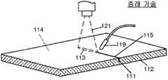
도 1에 도시된 바와 같이, 레이저 스코어링 동안에, 통기부가 스코어 라인(115)을 따라서 유리(112)의 주 표면(114)에 만들어진다. 통기부를 만들기 위하여, 작은 초기 균열(111)이 상기 유리 표면의 엣지 중 하나의 엣지 근처의 유리 표면에 형성되며, 이후 냉각 노즐(119)에 의해 만들어진 냉각 구역 다음의 유리 표면에 풋프린트(113, footprint)를 갖는 레이저 광 빔(121)을 전파시킴으로서 통기부로 변형된다. 레이저 광 빔에 의한 유리의 가열과 쿨란트에 의한 가열 직후의 냉각은 열 구배 및 대응하는 응력장을 만들고, 이는 통기부를 형성하는 초기 균열의 전파에 기여한다.As shown in FIG. 1, during laser scoring, vents are made in the
본 출원인의 미국특허 공개번호 제2008/0264994호(이후 '994 공보)는 이동하는 유리 리본의 레이저 스코어링용 시스템을 개시하고 있고, 상기 시스템에서 이동하는 캐리지가 선형 트랙을 따라 이동하며 상기 선형 트랙은 상기 유리 리본의 이동 방향을 횡단하는 라인에 대해 각도(α)로 경사져 있다.Applicant's US Patent Publication No. 2008/0264994 (hereafter '994 publication) discloses a system for laser scoring of moving glass ribbons, in which the moving carriage moves along a linear track and the linear track It is inclined at an angle α with respect to the line traversing the moving direction of the glass ribbon.
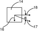
본 출원의 도 2 및 도 3은 '994 공보의 시스템을 개략적으로 나타내고 있다. 이들 도면에 있어서, 유리 리본은 부재 번호 13으로 지시되고, 이동하는 캐리지는 부재 번호 14로 지시되고, 선형 트랙은 부재 번호 15로 지시되고, 트랙용 지지 구조부(지지 프레임)는 부재 번호 11로 지시되며, 리본 생산 설비, 예를 들면, 융합 인발기(fusion draw machine)는 부재 번호 9로 지시되어 있다. '994 출원에 기재된 바와 같이, 고정된 기준 프레임(예를 들면, 도 2에서의 xyz 기준 프레임)에서 보여지는 바와 같이, 유리 리본은 벡터(16) 방향으로 속도(S리본)로 이동하고 캐리지는 벡터(17) 방향으로 속도(S캐리지)로 이동하며, 이 경우 S리본, S캐리지, 및 각도(α)는 아래 방정식 (1)을 만족한다:2 and 3 of the present application schematically show the system of the '994 publication. In these figures, the glass ribbon is indicated by
S캐리지 = S리본/sin α 방정식 (1)Scarriage = Sribbon / sin α equation (1)
이렇듯, 캐리지는 리본과 속도를 유지하거나, 또는, 보다 정확하게는, 상기 리본의 이동 방향과 평행한 상기 캐리지의 속도의 성분 크기가 S리본과 동일하다. 결론적으로, 리본으로부터 보여지는 바와 같이, 캐리지는 아래 방정식에 의해 주어진 속도(S스코어)로, 상기 리본의 이동 방향에 수직한 라인(7)을 따라 상기 리본을 가로지르는 즉, 벡터(18)의 방향으로 간단하게 이동한다:As such, the carriage maintains velocity with the ribbon, or more precisely, the component size of the velocity of the carriage parallel to the direction of movement of the ribbon is equal to the Sribbon . In conclusion, as can be seen from the ribbon, the carriage crosses the ribbon along a
S스코어 = S캐리지cos α방정식 (2)Sscore = Scarriage cos α equation (2)
'994 공보에 기재되어 있는 바와 같이, 레이저 광 빔을 제공하는 발광 장치 및 냉각 유체(예를 들면, 물)의 스트림을 제공하는 노즐이 캐리지와 연결되고 상기 캐리지가 선형 트랙을 따라서 이동함에 따라 리본의 폭을 가로지르는 통기부를 함께 형성한다. 여러 실시예에 있어서, 기계적 스코어링 헤드(예를 들면, 스코어링 휠)는 또한 유리 리본에서의 초기 균열을 형성하기 위한 캐리지와 연결된다. 선택적으로, 초기 균열은 캐리지와의 별도의 설비에 의해 형성될 수 있다.As described in the '994 publication, a light emitting device providing a laser light beam and a nozzle providing a stream of cooling fluid (eg water) are connected with the carriage and the ribbon moves as the carriage moves along a linear track. Together with the vents across the width of the form. In some embodiments, a mechanical scoring head (eg, scoring wheel) is also connected with the carriage for forming an initial crack in the glass ribbon. Optionally, the initial crack can be formed by a separate facility from the carriage.
도 4는 '994 공보의 이들 특징을 개략적으로 도시하고 있고, 여기서 부재 번호 21, 22, 및 23은 (1) 냉각 유체의 풋프린트, (2) 레이저 광 빔의 풋프린트, 및 (3) 초기 균열의 스코어링 공정 개시시의 위치를 나타내고, 부재 번호(31 및 32)는 개시가 완료된 이후의 이후 지점에서의 냉각 유체의 풋프린트의 위치와 레이저 광 빔의 풋프린트의 위치를 나타낸다.4 schematically illustrates these features of the '994 publication, wherein
'994 공보에 개시된 바와 같이, 제어 시스템은 캐리지의 이동을 제어하는데 사용되어 방정식 (1)이 만족될 수 있다. 인풋으로서, 제어 시스템은 리본의 속도를 모니터하는 리본이나 별도의 센서를 가이드 하는 롤러로부터의 S리본과 관련된 정보를 얻을 수 있다.As disclosed in the '994 publication, a control system can be used to control the movement of the carriage so that equation (1) can be satisfied. As an input, the control system can obtain information related to the Sribbon from the ribbon that monitors the ribbon speed or from a roller that guides a separate sensor.
'994 공보는 또한 선형 트랙(15)의 경사 각도(α)를 제어함으로써 방정식 (1)을 만족한다고 기재되어 있다. 그러나, 상기 공보는 α 변경에 대한 S캐리지의 변경 기준 또는 S캐리지 및/또는 α가 변경될 때 효율적인 통기부 형성을 유지하는 것과 관련된 문제점에 대해 기재되어 있지 않다. 본 발명은 이들 문제점을 처리하고 S리본에서의 변화에도 불구하고 효과적인 레이저 스코어링을 유지하는 방법과 기기를 제공한다.The '994 publication also describes that the equation (1) is satisfied by controlling the inclination angle α of the
본 발명의 제 1 특징에 따라, 유리 시트를 만드는 방법이 개시되어 있고, 상기 방법은:According to a first aspect of the invention, a method of making a glass sheet is disclosed, which method comprises:
(I) 시변(time-varying) 속도(S리본)를 갖는 이동하는 유리 리본(13)을 형성하는 단계;(I) forming a moving
(Ⅱ) (a) 속도(S캐리지)로 선형 트랙(15)을 따라, 발광 장치(51)와 노즐(119)을 지지하는 캐리지(14)를 병진이동하는 단계;(II) (a) translating the
(b) 상기 캐리지(14)의 제 2 이동 성분이 상기 유리 리본(13)과 속도를 유지하도록 S캐리지, 각도(α), 또는 상기 S캐리지 및 상기 각도(α) 양자를 동적으로 조정하는 단계; 및(b) dynamically adjusting the Scarriage , the angle α, or both the Scarriage and the angle α such that the second moving component of the
(c) 발광 장치(51)에 의해 발광된 광 빔을 만드는 상기 레이저(41)의 파워(P레이저)를 변경시킴으로써 단계 (Ⅱ)(b)의 동적 조정을 보상하는 단계;를 포함한 방법에 의해 상기 유리 리본의 이동 방향을 횡단하는 라인(7)을 따라서 상기 유리 리본(13)의 표면상에 통기부를 형성하는 단계; 및(c) compensating for the dynamic adjustment of step (II) (b) by changing the power (Plaser ) of the
(Ⅲ) 단계 (Ⅱ)에서 형성된 상기 통기부를 따라서 상기 유리 리본(13)으로부터 유리 시트를 분리하는 단계를 포함하고,(III) separating the glass sheet from the
상기 캐리지의 이동이 (i) 상기 라인(7)에 평행한 제 1 성분(18)과 (ⅱ) 상기 유리 리본(13)의 이동 방향에 평행한 제 2 성분(16)을 갖도록, 상기 선형 트랙은 상기 라인(7)에 대해 각도(α)로 경사지고, 상기 발광 장치(51)는 레이저(41)에 의해 만들어진 광 빔을 발광하고 상기 노즐(119)은 냉각 유체를 방사한다.The linear track such that the movement of the carriage has (i) a
본 발명의 제 2 특징에 따라, 상기 제 1 특징에 따른 방법이 제공되며, 여기서,According to a second aspect of the invention there is provided a method according to the first aspect, wherein
(i) S리본은:(i) Sribbon silver:
S리본 = S0 + △S0의 형태를 취하고,Sribbon = S0 + ΔS0 ,
여기서 S0 및 △S0는 각각, 상기 리본의 속도의 공칭 일정한 성분 및 시변 성분이고; 그리고Wherein S0 and ΔS0 are nominally constant components and time-varying components of the velocity of the ribbon, respectively; And
(ⅱ) |△S0| > 0.03S0일 때, 단계 (Ⅱ)(b)는 α를 변경하는 단계를 포함한다.(Ii) | △ S0 | When> 0.03S0 , step (II) (b) includes changing α.
본 발명의 제 3 특징에 따라, 상기 제 1 특징에 따른 방법이 제공되며, 이 경우:According to a third aspect of the invention there is provided a method according to the first aspect, in which case:
(i) 단계 (Ⅱ)(b)는 α를 변경하는 단계를 포함하고;(i) step (II) (b) comprises changing α;
(ⅱ) 리본에서, 발광 장치로 발광된 광 빔은 길이(L)와 폭(W)을 갖고;(Ii) in the ribbon, the light beam emitted by the light emitting device has a length L and a width W;
(ⅲ) 상기 발광 장치는 L을 결정하는 제 1 렌즈 유닛 및 W를 결정하는 제 2 렌즈 유닛을 포함하고;(Iii) the light emitting device comprises a first lens unit for determining L and a second lens unit for determining W;
(ⅳ) 상기 제 1 렌즈 유닛은 적어도 하나의 렌즈 소자를 포함하며;(Iii) the first lens unit comprises at least one lens element;
(v) 단계 (Ⅱ)는 α 변경의 결과로서 상기 라인에 대한 상기 광 빔의 정위 변경을 보상하도록 적어도 하나의 렌즈 소자의 각도 정위를 조정하는 단계를 더 포함한다.(v) Step (II) further comprises adjusting the angular orientation of the at least one lens element to compensate for the displacement of the light beam relative to the line as a result of the α change.
본 발명의 제 4 특징에 따라, 특징 3의 방법이 제공되며, 여기서 제 2 렌즈 유닛은 적어도 하나의 렌즈 소자를 포함하고 상기 렌즈 소자의 각도 정위는 α가 변경됨에 따라 상기 캐리지에 대해 일정하게 유지된다.According to a fourth aspect of the invention there is provided a method of feature 3, wherein the second lens unit comprises at least one lens element and the angular orientation of the lens element remains constant with respect to the carriage as α is changed. do.
본 발명의 제 5 특징에 따라, 상기 제 3 특징이나 또는 제 4 특징의 방법이 제공되며 제 1 렌즈 유닛 및 제 2 렌즈 유닛 각각은 단지 하나의 렌즈 소자를 수용한다.According to a fifth aspect of the invention, a method of the third or fourth aspect is provided wherein each of the first and second lens units houses only one lens element.
본 발명의 제 6 특징에 따라, 상기 제 1 특징의 방법이 제공되며:According to a sixth aspect of the invention, a method of the first aspect is provided:
(i) S리본은:(i) Sribbon silver:
S리본 = S0 + △S0의 형태를 취하고,Sribbon = S0 + ΔS0 ,
여기서 상기 S0 및 상기 △S0는 각각 상기 리본의 속도의 공칭 일정한 성분 및 시변 성분이고; 및Wherein S0 and DELTA S0 are each a nominal constant component and a time varying component of the velocity of the ribbon; And
(ⅱ) |△S0| ≤ 0.03S0일 때, α는 단계 (Ⅱ)(b)에서 일정하게 유지된다.(Ii) | △ S0 | When ≤ 0.03S0 , α remains constant in step (II) (b).
본 발명의 제 7 특징에 따라, 상기 제 6 특징의 방법이 제공되며, 단계 (Ⅱ)(c)의 P레이저의 변경은 아래 기재된 식을 만족하고:According to a seventh aspect of the invention, there is provided a method of the sixth aspect, wherein the alteration of the Plaser in step (II) (c) satisfies the equation described below:
dP레이저/dS리본 = k?ctn(α),dPlaser / dSribbon = k? ctn (α),
여기서 k는 상수이다.Where k is a constant.
본 발명의 제 8 특징에 따라, 상기 특징 7의 방법이 제공되며, 여기서 P레이저는 최대 레이저 파워의 퍼센트로 나타내어지며 k <1.0이다.According to an eighth aspect of the invention, there is provided the method of
본 발명의 제 9 특징에 따라, 상기 특징 1의 방법이 제공되며, 여기서 단계 (Ⅱ)는 레이저 또는 상기 레이저용 지지 구조부에 부착된 제 1 단부와 선형 트랙 또는 상기 선형 트랙용 지지 구조부에 부착된 제 2 단부를 구비한 하우징에서 레이저 광을 둘러싸는 가요성 레이저 빔 이송 시스템을 포함하여 경로를 따라 발광 장치에 레이저로부터의 레이저 광을 전도하는 단계를 포함하고,According to a ninth aspect of the invention there is provided the method of feature 1, wherein step (II) is a first end attached to a laser or the support structure for the laser and attached to the linear track or the support structure for the linear track. Conducting laser light from the laser to the light emitting device along a path including a flexible laser beam transport system surrounding the laser light in a housing having a second end,
상기 하우징은 제 1 단부 및 제 2 단부 서로에 대해 3차원으로 회전 및 병진이동을 허용하는 적어도 하나의 조인트와 적어도 하나의 연장 튜브를 포함한다.The housing includes at least one joint and at least one extension tube to allow rotation and translation in three dimensions with respect to each other at the first and second ends.
본 발명의 제 10 특징에 따라, 상기 특징 1 - 특징 9 중 어느 한 특징의 방법이 제공되며, 이 경우 유리 리본은 하향인발 공정에 의해 형성된다.According to a tenth aspect of the invention, there is provided a method of any one of features 1-9 above, wherein the glass ribbon is formed by a downdraw process.
본 발명의 제 11 특징에 따라, 상기 특징 1 - 특징 10 중 어느 한 특징의 방법이 제공되며, 이 경우 유리 시트는 디스플레이장치용 기판이다.According to an eleventh aspect of the invention, there is provided a method of any one of features 1 to 10 above, wherein the glass sheet is a substrate for a display device.
본 발명의 제 12 특징에 따라, 유리 시트를 만드는 방법이 개시되어 있고, 상기 방법은:According to a twelfth aspect of the invention, a method of making a glass sheet is disclosed, which method comprises:
(I) 이동하는 유리 리본(13)을 형성하는 단계;(I) forming a moving
(Ⅱ) 선형 트랙(15)을 따라, 발광 장치(51) 및 노즐(119)을 지지하는 캐리지(14)를 병진이동하는 단계를 포함한 방법에 의해 상기 유리 리본의 이동 방향을 횡단하는 라인(7)을 따라 상기 유리 리본(13)의 표면에 통기부를 형성하는 단계; 및(II) A
(Ⅲ) 단계 (Ⅱ)에서 형성된 상기 통기부를 사용하여 상기 리본(13)으로부터 상기 유리 시트를 분리하는 단계;를 포함하고,(III) separating the glass sheet from the
상기 캐리지의 이동이 (i) 상기 라인(7)에 평행한 제 1 성분(18)과 (ⅱ) 상기 리본(13)의 이동 방향에 평행한 제 2 성분(16)을 구비하도록 상기 선형 트랙은 라인(7)에 대해 각도(α)로 경사지고, 상기 발광 장치(51)는 레이저(41)에 의해 만들어진 광 빔을 발광하고 상기 노즐(119)은 냉각 유체를 방사하고,The linear track is such that the movement of the carriage comprises (i) a
(i) 상기 리본(13)에서, 발광 장치로 발광된 광 빔은 길이(L) 및 폭(W)을 갖고;(i) in the
(ⅱ) 상기 발광 장치(51)는 L을 결정하는 제 1 렌즈 유닛(53)과 W를 결정하는 제 2 렌즈 유닛(55)을 포함하고;(Ii) the
(ⅲ) 상기 제 1 렌즈 유닛(53)은 적어도 하나의 렌즈 소자(81)를 포함하고;(Iii) the
(ⅳ) 상기 α는 상기 캐리지(14)의 제 1 및 제 2 성분(18, 16)의 이동의 상대 크기를 변경하도록 변경되고;(Iii) the α is changed to change the relative magnitude of the movement of the first and second components (18, 16) of the carriage (14);
(v) 상기 적어도 하나의 렌즈 소자(81)의 각도 정위는 상기 α의 변화의 결과로서 상기 라인(7)에 대한 상기 광 빔의 정위의 변화를 보상하도록 조정된다.(v) The angular positioning of the at least one
본 발명의 제 13 특징에 따라, 상기 제 12 특징의 방법이 제공되며, 이 경우 제 2 렌즈 유닛은 적어도 하나의 렌즈 소자를 포함하고 상기 렌즈 소자의 각도 정위는 α가 변경됨에 따라 캐리지에 대해 일정하게 유지된다.According to a thirteenth aspect of the invention, there is provided a method of the twelfth aspect, in which case the second lens unit comprises at least one lens element and the angle orientation of the lens element is constant with respect to the carriage as α is changed. Is maintained.
본 발명의 제 14 특징에 따라, 상기 제 12 특징의 방법이 제공되며, 이 경우 제 1 렌즈 유닛과 제 2 렌즈 유닛 각각은 단지 하나의 렌즈 소자를 수용한다.According to a fourteenth aspect of the invention, there is provided the method of the twelfth aspect, in which case the first lens unit and the second lens unit each receive only one lens element.
본 발명의 제 15 특징에 따라, 상기 제 12 특징 내지 제 14 특징 중 어느 한 특징의 방법이 제공되며, 이 경우 유리 리본은 하향인발 공정에 의해 형성된다.According to a fifteenth aspect of the invention, there is provided a method of any one of the twelfth to fourteenth aspects, in which case the glass ribbon is formed by a downdraw process.
본 발명의 제 16 특징에 따라, 상기 제 12 특징 내지 제 15 특징 중 어느 한 특징의 방법이 제공되며, 이 경우 유리 시트는 디스플레이장치용 기판이다.According to a sixteenth aspect of the invention, there is provided a method of any one of the twelfth to fifteenth aspects, in which case the glass sheet is a substrate for a display device.
본 발명의 제 17 특징에 따라, 유리 시트를 만드는 방법이 개시되어 있고, 상기 방법은:According to a seventeenth aspect of the invention, a method of making a glass sheet is disclosed, which method comprises:
(I) 이동하는 유리 리본(13)을 성형하는 단계;(I) molding the moving
(Ⅱ) (a) 선형 트랙(15)을 따라서 발광 장치(51)와 노즐(119)을 지지하는 캐리지(14)를 병진이동하는 단계; 및(II) (a) translating the
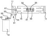
(b) 레이저(41) 또는 상기 레이저용 지지 구조부에 부착된 제 1 단부(65)와 선형 트랙(15) 또는 상기 선형 트랙용 지지 구조부(11)에 부착된 제 2 단부(67)를 구비한 하우징에서 레이저 광(43)을 둘러싸는 가요성 레이저 빔 이송 시스템(61)을 포함하여 경로를 따라 상기 발광 장치(51)에 상기 레이저(41)로부터의 레이저 광(43)을 전도하는 단계;를 포함한 방법에 의해 상기 유리 리본의 이동 방향을 횡단하는 라인(7)을 따라서 상기 유리 리본(13)의 표면에 통기부를 형성하는 단계;(b) a
(Ⅲ) 단계 (Ⅱ)에서 형성된 상기 통기부를 사용하여 상기 유리 리본(13)으로부터 유리 시트를 분리하는 단계를 포함하고,(III) separating the glass sheet from the
상기 캐리지의 이동이 (i) 상기 라인(7)에 평행한 성분(18)과 (ⅱ) 상기 유리 리본(13)의 이동 방향에 평행한 성분(16)을 갖도록 상기 선형 트랙은 상기 라인(7)에 대해 각도(α)로 경사지고, 상기 발광 장치(51)는 레이저 광 빔을 발광하고 상기 노즐(119)은 냉각 유체를 방사하며,The linear track is such that the movement of the carriage has (i)
상기 하우징은 제 1 및 제 2 단부(65, 67) 서로에 대해 3차원으로 회전 및 병진이동을 가능하게 하는 적어도 하나의 조인트(62) 및 적어도 하나의 연장 튜브(64)를 포함한다.The housing includes at least one joint 62 and at least one
본 발명의 제 18 특징에 따라, 상기 제 17 특징의 방법이 제공되며, 이 경우, 가요성 레이저 빔 이송 시스템은 빔 익스팬더를 포함한다.According to an eighteenth aspect of the invention, there is provided the method of the seventeenth aspect, wherein the flexible laser beam delivery system includes a beam expander.
본 발명의 제 19 특징에 따라, 상기 제 17 특징 또는 제 18 특징의 방법이 제공되며, 이 경우 유리 리본은 하향인발 공정에 의해 형성된다.According to a nineteenth aspect of the invention, there is provided a method of the seventeenth or eighteenth aspect, wherein the glass ribbon is formed by a downdraw process.
본 발명의 제 20 특징에 따라, 상기 특징 17 내지 특징 19 중 어느 한 특징의 방법이 제공되며, 이 경우 유리 시트는 디스플레이장치용 기판이다.According to a twentieth aspect of the present invention, there is provided a method of any one of
상기 방법을 실행하기 위한 기기가 또한 개시되어 있다.An apparatus for carrying out the method is also disclosed.
본 명세서의 여러 특징의 상기 기재에서 사용된 참조 번호는 단지 이해를 돕기 위해 예시적으로 사용한 것으로서, 본 발명을 한정하기 위함이 아니라는 것을 알 수 있을 것이다. 더욱 일반적으로, 상기 일반적인 설명과 아래 상세한 설명 모두는 본 발명의 예시적인 것으로서 본 발명이 이로써 한정되지 않고 본 발명의 특징과 특성의 전반적인 이해를 돕기 위한 것이라는 것을 알 수 있을 것이다.It is to be understood that the reference numerals used in the above description of the various features of the present specification are by way of example only for purposes of understanding, and are not intended to limit the present invention. More generally, it will be appreciated that both the foregoing general description and the following detailed description are exemplary of the invention and are intended to assist the overall understanding of the features and characteristics of the invention, without being limited thereto.
본 발명의 추가적인 특징과 장점은 아래 기재된 상세한 설명에 기재되어 있고, 당업자라면 본 명세서에 기재된 바와 같이 본 발명을 실시함으로써 상기 특징과 장점을 알 수 있을 것이다. 첨부 도면은 본 발명의 이해를 더욱 돕기 위해 포함되어 있으며, 본 명세서의 일부를 이루도록 통합되어 있다. 본 명세서와 도면에 개시된 발명의 여러 특징이 일부 조합되거나 모두 조합되어 사용될 수 있음을 알 수 있을 것이다.Additional features and advantages of the invention are set forth in the detailed description set forth below, and one of ordinary skill in the art will recognize the above features and advantages by practicing the invention as described herein. The accompanying drawings are included to provide a further understanding of the invention, and are incorporated into and constitute a part of this specification. It will be appreciated that various features of the invention disclosed in this specification and in the drawings may be used in combination or in combination.
도 1은 레이저 스코어링 공정을 개략적으로 도시한 도면이다.
도 2는 '994 공보에 따른 레이저 스코어링 시스템을 개략적으로 도시한 도면이다.
도 3은 도 2의 캐리지의 이동을 보다 상세하게 나타낸 도면이다.
도 4는 스코어링 공정 개시 시에 그리고 이후 시점에서의 냉각 유체, 레이저 광 빔, 및 초기 균열의 위치를 개략적으로 나타낸 도면이다.
도 5는 (1) S스코어(좌측 수직 축선) 대 S리본(수평 축선)(곡선 57); 그리고 (2) 최대 레이저 파워의 퍼센트(우측 수직 축선) 대 S리본(수평 축선)(곡선 59)을 나타낸 그래프로서, 상기 S스코어 및 상기 S리본은 이들 곡선에 대해 밀리미터/초;α = 3.8°이다.
도 6은 플라잉 광학 헤드에 레이저 광을 제공하기 위한 시스템의 개략적인 도면이다.
도 7은 플라잉 광학 헤드에 레이저 광을 제공하기 위한 가요성 레이저 빔 이송 시스템을 사용하는 일 실시예의 사시도이다.
도 8은 도 7의 시스템의 측면도이다.
도 9는 도 7의 시스템의 평면도이다.
도 10은 본 실시예에서 사용된 회전 미러와 제 1 및 제 2 렌즈 유닛의 위치를 나타내기 위하여, 하우징의 일부가 제거된 상태의, 도 7의 플라잉 광학 헤드의 사시도이다.
도 11은 도 7의 플라잉 광학 헤드의 제 1 렌즈 유닛의 사시도이다.
도 12는 레이저 빔이 도 7의 플라잉 광학 헤드를 통과함에 따라 상기 레이저 빔의 정위와 형상을 개략적으로 도시한 도면이다.1 schematically illustrates a laser scoring process.
2 is a schematic illustration of a laser scoring system according to the '994 publication.
3 is a view showing in more detail the movement of the carriage of FIG.
4 is a schematic representation of the location of the cooling fluid, the laser light beam, and the initial crack at the start of and after the scoring process.
5 (1) Sscore (left vertical axis) vs. Sribbon (horizontal axis) (curve 57); And (2) a graph showing the percent of maximum laser power (right vertical axis) versus Sribbon (horizontal axis) (curve 59), where the Sscore and the Sribbon are in millimeters / sec for these curves; α = 3.8 ° to be.
6 is a schematic diagram of a system for providing laser light to a flying optical head.
7 is a perspective view of one embodiment using a flexible laser beam transport system for providing laser light to a flying optical head.
8 is a side view of the system of FIG.
9 is a top view of the system of FIG. 7.
FIG. 10 is a perspective view of the flying optical head of FIG. 7 with a portion of the housing removed to show the position of the rotating mirror and the first and second lens units used in this embodiment.
FIG. 11 is a perspective view of a first lens unit of the flying optical head of FIG. 7.
FIG. 12 is a diagram schematically illustrating the position and shape of the laser beam as the laser beam passes through the flying optical head of FIG. 7.
일반적으로, 유리 리본의 속도는 공칭 성분(S0)과 공칭 값으로부터의 오프셋(△S0)으로 이루어져 기재될 수 있으며:In general, the velocity of the glass ribbon can be described by consisting of a nominal component (S0 ) and an offset from the nominal value (ΔS0 ):
S리본 = S0 + △S0방정식 (3)Sribbon = S0 + △ S0 equation (3)
상기 S0 및 상기 △S0 모두는 시간의 함수일 수 있다. 예를 들면, S0는 예를 들면, 생산율에서, 의도된 변화의 결과로서 변할 수 있는 한편, △S0는 공정 조건에서의 의도되지 않은 변화의 결과로서 변할 수 있다. 전형적으로, S0에서의 변화에 따른 S리본에서의 변화는 △S0때문에 S리본에서의 변화보다 덜 발생하지만, 이와 반대인 경우가 예를 들면, 일련의 공칭 리본 속도가 테스트될 필요가 있는 새로운 공정의 디버깅(debugging) 동안에 발생할 수 있다. 아래 기재된 사항을 설명하기 위하여, S0가 중요한 시간 계획 내내 일정하고 △S0가 상기 S0에 대한 리본의 속도에서의 변동을 나타내며 의도된 변동과 의도되지 않은 변동을 포함한다는 것을 알 수 있다.Both S0 and ΔS0 may be a function of time. For example, S0 may change as a result of an intended change, for example in production rate, while ΔS0 may change as a result of an unintended change in process conditions. Typically, the change in the Sribbon according to the change in the S0 is S0 △ This occurs less frequently than changes in the Sribbon , but vice versa, for example, may occur during debugging of a new process where a series of nominal ribbon velocities need to be tested. To explain the details described below, constant throughout the time that the S0 significant planning and △ S0 that represents the variations in the ribbon speed relative to the S0 can be seen that contain the intended change and unintended variations.
S리본이 변함에 따라 캐리지가 리본과의 속도를 유지시키기 위하여, 즉, 상기 리본으로부터 보여지는 바와 같이 상기 캐리지의 이동이 일직선이 되게 하기 위하여, S캐리지 및 α 중 하나 또는 양자가 변경될 필요가 있다. 전형적으로, S캐리지를 변경하는 단계는 α를 변경하는 단계보다 간단할 수 있다. 그러나, 본 발명에 따라, S캐리지가 리본으로부터 분리된 유리 시트의 엣지의 품질을 저하시키지 않으면서 제한된 범위 내내 변경될 수도 있음을 알 수 있다.As the Sribbon changes, one or both of the Scarriage and α need to be changed to maintain the speed of the carriage with the ribbon, i.e., to align the movement of the carriage as seen from the ribbon. have. Typically, changing the Scarriage may be simpler than changing the α. However, it can be seen that according to the invention, the Scarriage may be changed over a limited range without degrading the quality of the edge of the glass sheet separated from the ribbon.
특히, 레이저 스코어링 공정을 적용가능한 공정 윈도우 내에서 유지하기 위하여 S캐리지가 변함에 따라 레이저 파워가 제어될 필요가 있음을 발견하였다. 특히, 레이저 파워는 S캐리지가 증가함에 따라 증가되고 감소함에 따라 감소될 필요가 있다. 그러나, 시스템을 그 공정 윈도우에 유지시키면서 레이저 파워에 대해 만들어질 수 있는 레벨 변화는 매우 제한되었다고 밝혀졌다. 이러한 효과는 도 5에 도시되어 있고, 상기 도 5는 수평 축선을 따라서 mm/sec로 S리본을, 좌측 수직 축선을 따라서 mm/sec로 스코어링 속도를, 그리고 우측 수직 축선을 따라서 퍼센트로 레이저 파워를 나타낸다. 상기 도면에 도시된 곡선은 3.8°의 α 값에 대해 얻어진 측정된 데이터에 기초한다.In particular, it has been found that the laser power needs to be controlled as the Scarriage changes to maintain the laser scoring process within the applicable process window. In particular, the laser power needs to be increased and decreased as the Scarriage is increased. However, it has been found that the level change that can be made to the laser power while keeping the system at its process window is very limited. This effect is illustrated in FIG. 5, which shows the Sribbon at mm / sec along the horizontal axis, the scoring speed at mm / sec along the left vertical axis, and the laser power in percent along the right vertical axis. Indicates. The curve shown in this figure is based on measured data obtained for an α value of 3.8 °.
도 5의 데이터를 만든 실험은 리본으로부터 분리된 유리 시트의 엣지 특성이 상기 리본의 공칭 속도(이 경우 50 mm/sec)에 대해 좁은 범위의 ±3%에서 반복적으로 허용가능하다는 것을 나타낸다. 즉, 상기 방정식 (3)과 관련하여, 레이저 파워 조정 및 캐리지 속도의 조합은 |△S0| ≤ 0.03?S0일 때, 그러나 |△S0| > 0.033?S0일 때 리본 속도의 변화를 조정하도록 사용될 수 있으며, α는 또한 신뢰할만한 엣지 품질을 제공하도록 변경될 필요가 있다.The experiments making the data of FIG. 5 show that the edge properties of the glass sheets separated from the ribbon are repeatedly acceptable at a narrow range of ± 3% for the ribbon's nominal speed (50 mm / sec in this case). That is, with respect to equation (3) above, the combination of laser power adjustment and carriage speed is | ΔS0 | When ≤ 0.03? S0 , but | △ S0 | It can be used to adjust the change in ribbon speed when> 0.033? S0 , and α also needs to be changed to provide reliable edge quality.
도 5는 또한 S리본에서의 변화를 보상하는데 필요한 레이저 파워의 변화가 S리본의 선형 함수일 수 있음을 나타내고 있다. 이러한 일차 종속은 레이저 스코어링 공정의 제어를 용이하게 할 수 있다. 이러한 실시예를 위하여, dP레이저/dS리본이 dP레이저/dS리본 = k?ctn(α)로 나타내어질 수 있으며, 여기서 k는 상수이다. 즉, S캐리지가 증가할 때 S리본에서의 증가와 맞춰지도록 증가하는 스코어링 속도가 ctn(α)(즉, dS스코어링/dS리본 = ctn(α); 상기 방정식 (1) 및 (2) 참조)인 한편, 신뢰할만한 엣지 형성을 유지하기 위해 레이저 파워가 증가될 필요가 있는 속도는 k 값에 따른 ctn(α) 이하이거나, 또는 그 이상이거나 또는 동일할 수 있다. 도 5의 데이터의 경우에 있어서, 이 경우 레이저 파워가 최대 파워의 퍼센트로 나타나며, k는 1.0 이하이다. 명확한 바와 같이, 임의의 특별한 경우 및 레이저 파워(예를 들면, 최대 파워 퍼센트, 와트 등)용 임의의 특별한 유닛에 대한 k의 특정값이 본 발명으로부터 당업자에 의해 용이하게 결정될 수 있다.5 is also a change of the laser power required to compensate for the change in S represents theribbon can be a linear function of the Sribbon. This primary dependency may facilitate the control of the laser scoring process. For this embodiment, the dPlaser / dSribbon can be represented as dPlaser / dSribbon = k? Ctn (α), where k is a constant. (; See the equation (1) and (2) That is, dSscoring / dSribbon = ctn (α)) That is, the scoring speed ctn (α), that when the Scarriage increased increased to align with an increase in the Sribbon On the other hand, the speed at which the laser power needs to be increased to maintain reliable edge formation may be equal to or less than, or more than, ctn (α) depending on the k value. In the case of the data of FIG. 5, the laser power in this case is expressed as a percentage of the maximum power, k being 1.0 or less. As should be clear, the specific value of k for any particular case and for any particular unit for the laser power (eg, maximum power percent, watts, etc.) can be readily determined by one skilled in the art from the present invention.
도 6 - 도 9에는 S리본에서의 변화, 예를 들면, 변화 > 0.03?S0를 조정하도록 각도(α)를 변경시키는데 사용될 수 있는 기기가 도시되어 있다. 특히, 도 6은 이러한 목적에 사용될 수 있는 기기의 예시적인 전반적인 장치를 개략적으로 나타내고 있는 한편, 도 7 - 도 9는 특정 실시예를 예시적으로 나타내고 있다. 도 6에 있어서, 개별 유리 시트가 분리되는 유리 리본은 부재 번호 13으로 지시되고, 이동가능한 캐리지용 선형 트랙은 부재 번호 15로 지시되며, 리본을 만드는 설비, 예를 들면, 융합 인발기가 부재 번호 9로 지시된다. 간단하게 나타내가 위하여, 캐리지가 도 6 - 도 9에서 플라잉(flying) 광학 헤드(51)로 나타나 있으며, 상기 캐리지가 냉각 유체용 노즐을 포함한 다른 설비를 포함할 수 있음을 알 수 있을 것이다. 플라잉 광학 헤드(51)는 레이저(41)에 의해 만들어진 레이저 빔(43)을 받아 상기 빔이 리본(13) 쪽으로 나아가게 한다. 도 1 - 도 4와 관련하여 상기 기재된 바와 같이, 냉각 유체와 조합된 레이저 빔은 유리에 형성된 초기 균열을 연장시켜 개별 유리 시트가 리본으로부터 분리되는 상기 리본의 폭을 가로지르는 통기부를 만든다.6-9 show a device that can be used to change the angle α to adjust for a change in the Sribbon , eg, a change> 0.03-S0 . In particular, FIG. 6 schematically illustrates an exemplary overall apparatus of a device that may be used for this purpose, while FIGS. 7-9 illustrate specific embodiments by way of example. In Fig. 6, the glass ribbon from which the individual glass sheets are separated is indicated by the
도 6에 있어서, 도시된 레이저 빔은 미러(45 및 47)에 의해 플라잉 광학 헤드로 가이드되고, 상기 미러는 광을 레이저로부터 수광하고 상기 광을 플라잉 광학 헤드로 전송하기 위해 적합한 개구나 또는 커플링(도시 생략)을 구비한 하우징(49) 내에 위치된다. 미러(45 및 47)의 위치와 각도 정위는 능동 제어될 수 있어, 각도(α)가 변함에 따라 플라잉 헤드에서 목표한 레이저 빔을 유지시킨다. 단지 2개의 미러가 도시되어 있지만, 필요에 따라 미러가 추가되어 사용될 수 있다.In FIG. 6, the laser beam shown is guided to the flying optical head by
α 변화를 조정하도록 사용되는 것 외에도, 미러의 각도 정위 및 위치는 또한 온도 변화(예를 들면, 실내 온도로부터 유리 리본의 제조와 관련하여 상승된 작동 온도까지), 기계적 진동 등에 의해 야기된, 레이저(41)와 트랙(15) 사이의 상대 이동을 보상하는데 사용될 수 있다. 필요한 파워 레벨 때문에, 레이저(41)는 일반적으로 매우 대량이고 이에 따라 제조 셋팅 시 종종 트랙(15)에 사용된 것과 별도의 지지 구조부 상에 장착될 것이다. 결론적으로, 레이저(41) 및 트랙(15)은 서로에 대해 상대이동할 수 있고, 이에 따라 플라잉 광학 헤드에서 레이저 빔의 연속 조준을 필요로 한다. 레이저(및/또는 그의 지지 시스템)의 위치와 선형 트랙(및/또는 그의 지지 시스템)의 위치에 대해 적당한 트랜스듀서로부터의 인풋 데이터를 얻는 컴퓨터 제어 시스템을 사용하여 미러(45 및 47)의 정위 및/또는 위치를 능동적으로 변경시킴으로써 상기 기재한 바와 같은 연속 조준이 달성될 수 있다.In addition to being used to adjust the α change, the angle orientation and position of the mirror may also be caused by a change in temperature (e.g., from room temperature to elevated operating temperature in connection with the manufacture of the glass ribbon), mechanical vibrations, etc. It can be used to compensate for relative movement between 41 and
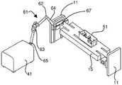
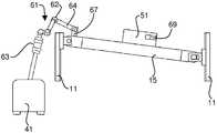
도 7 - 도 9는 온도 변화, 기계적 진동 등에 의한 레이저(41)와 트랙(15)의 상대 위치의 변화 뿐만 아니라 α의 변화를 수동적으로 수용할 수 있는 일 실시예를 나타낸 도면이다. 이러한 실시예는 가요성 레이저 빔 이송 시스템(61)을 포함하고, 상기 레이저 빔 이송 시스템은 레이저 광을 하우징에서 둘러싸고, 상기 하우징은 레이저(41) 또는 상기 레이저용 지지 구조부에 고정된 제 1 단부(65)와, 선형 트랙(15)이나 또는 예를 들면, 도 7 - 도 9에서의 지지 구조부(11)와 같은 선형 트랙용 지지 구조부에 고정된 제 2 단부(67)를 구비한다. 제 2 단부(67)를 선형 트랙(15)에 부착하는 것은 트랙, 제 2 단부 및 광학 헤드가 α가 변함에 따라 이동하기 때문에, 각도(α)가 변함에 따라, 레이저 빔이 플라잉 광학 헤드(51)에서 목표한 바와 같이 유지되는 장점이 있다.7-9 illustrate an embodiment in which a change in α as well as a change in the relative position of the
도 7 - 도 9에 도시된 바와 같이, 이송 시스템의 하우징은 제 1 단부(65) 및 제 2 단부(67)가 서로에 대해 3차원으로 회전 및 병진이동을 허용하는 적어도 하나의 조인트(62) 및 적어도 하나의 연장 튜브(64)를 포함한다. 여하튼, 이송 시스템의 제 1 단부와 제 2 단부는 레이저로부터 시스템으로의 광의 인풋이나 또는 플라잉 광학 헤드로의 광의 아웃풋 중 어느 하나를 실질적으로 저하시키지(degrading) 않으면서 서로에 대해 이동할 수 있다. 이러한 구성은 설치된 후 조작자 중재 없이 연장된 시간 간격 동안에 작동할 수 있게 하는 강성의 시스템을 제공하기 때문에 매우 유리하다. 적어도 하나의 조인트와 적어도 하나의 연장 튜브의 조합은 또한 스코어링 시스템의 설치, 조정 및 서비스를 용이하게 한다. 이와 관련하여, 빔 지향 정확도 요구조건은 매우 엄격하고; 예를 들면, 플라잉 광학 헤드의 중앙선으로부터 빔의 중앙의 편차에 대한 적당한 명세서에 의하면 상기 편차는 이송 시스템의 최종 미러로부터 3미터 이상의 거리에서 ±100㎛ 이하일 수 있다는 것을 알 수 있을 것이다.As shown in FIGS. 7-9, the housing of the conveying system includes at least one joint 62 in which the
또한 도 7 - 도 9에 도시된 바와 같이, 가요성 레이저 빔 이송 시스템(61)은 빔 익스팬더(63)를 포함하여 레이저 광을 플라잉 광학 헤드에 이후 유리 리본에 용이하게 이동할 수 있다. "Scoring of Non-Flat Materials"를 발명의 명칭으로 하는 본 출원인의 미국 특허출원번호 제12/220,948호(이후 '948 출원이라 함)를 참조하기 바람. 이송 시스템은 또한 원형 편광자(도 7 - 도 9에는 도시 생략됨)를 포함할 수 있다. 시스템은 미국 미시간주 Wixom에 위치한 American Laser Enterprises가 제조한 것과 같은 상업적으로 이용가능한 설비를 사용해 만들어질 수 있다.7-9, the flexible laser
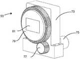
플라잉 광학 헤드(51)를 살펴보면, 도 10에 도시된 바와 같이, 상기 플라잉 헤드는 리본(13) 상의 레이저 빔의 길이를 제어하는 제 1 렌즈 유닛(53)과, 레이저 빔의 폭을 제어하는 제 2 렌즈 유닛(55)과, 리본 쪽으로 빔을 나아가게 하는 회전 미러(69)를 포함할 수 있다. 제 1 렌즈 유닛은 예를 들면 도 2의 z-축선에 따른 방향으로(즉, 도 2에서 지면에 수직한 방향으로) 빔을 연장시키는 단일의 오목한 원통형 렌즈 소자를 포함하는 한편, 제 2 렌즈 유닛이 예를 들면, 트랙의 중심선을 통하는 평면에서 트랙(15)에 수직하고 도 2에서 x-y 평면에 평행한 방향으로 빔을 수축시키는 단일의 볼록한 원통형 렌즈 소자를 포함할 수 있다. 더 많은 렌즈 소자가 물론, 제 1 렌즈 유닛 및 제 2 렌즈 유닛에 사용되거나 또는 이 둘 모든 유닛에 사용될 수 있다.Referring to the flying
도 12는 전파하는 빔에서의 제 1 렌즈 유닛과 제 2 렌즈 유닛의 영향을 나타낸 도면이다. 도 12에 도시된 바와 같이, 빔은 원형 단면(83)을 갖고 화살표 91의 방향으로 전파하는 플라잉 광학 헤드에 진입한다. 빔이 상기 빔을 퍼트리는 제 1 렌즈 유닛(53)에 진입하여 상기 렌즈 유닛을 떠날 때 상기 빔은 부재 번호 85로 지시된 구성을 취한다. 이후, 빔은 제 2 렌즈 유닛을 통과하고 미러(69)에 의해 리본 상에서 반사된다. 도 12에 있어서, 제 2 렌즈 유닛과 미러의 결합된 효과가 부재 번호 93으로 나타나 있다. 트랙(15)이 수평이라면, 리본에서의 최종 빔은 도 12에서 부재 번호 89로 지시된 구성과 정위를 가질 수 있다. 그러나, 트랙(15)이 각도(α) 만큼 수평방향 아래로 틸트될 때, 리본에서, 빔은 도 12에서 부재 번호 87로 지시된 정위를 취한다. 즉, 빔이 각도(α) 만큼 상향으로 회전된다.12 is a diagram showing the influence of the first lens unit and the second lens unit on the propagating beam. As shown in FIG. 12, the beam enters the flying optical head having a
방정식 (1)이 만족되도록 S캐리지 및 α가 선택된다면, 경사진 빔이 일직선, 예를 들면, 라인(7)에서 리본을 가로질러 계속 병진이동하지만, 그러나 상기 빔의 장축(major axis)이 상기 라인을 따라서 더 이상 놓여있지 않다는 것을 알 수 있을 것이다. 실제로, 빔의 장축은 냉각 액체 및 초기 균열에 의해 가로질러진 경로와 더이상 완전하게 정렬되지 않기 때문에, 상기 빔의 경로와 상기 빔의 장축 사이의 이러한 오정렬이 신뢰할 수 없는 스코어링 및/또는 불량의 엣지 품질을 초래할 수 있다고 알려져 있다.If Scarriage and α are chosen such that equation (1) is satisfied, the tilted beam continues to translate across the ribbon in a straight line, for example, at
이러한 문제점을 해결하기 위하여, 제 1 렌즈 유닛이 도 11에 도시된 바와 같이 구성될 수 있어, 리본의 표면을 가로지르는 빔의 이동 방향과 정렬되는 빔의 장축의 정위를 초래하도록 렌즈 소자(81)의 실린더 축선(또는 만일 사용된다면, 다수의 렌즈 소자의 실린더 축선)이 회전될 수 있게 한다. 도 11에 도시된 바와 같이, 렌즈 유닛(53)은 기어(77)를 구동시키는 스테퍼 모터(75)에 장착된 하우징(73)을 포함하고, 상기 기어(77)는 이 결과, 렌즈 소자(81)가 고정된 보다 큰 기어(79)를 구동시킬 수 있다. 스테퍼 모터는 트랙(15)의 각도로 렌즈 소자(81)의 정위를 조정하는 제어기(도시 생략)에 의해 기동된다. 특히, 도 12에 도시된 바와 같이, 제어기는 실린더 축선의 렌즈 소자(또는 여러 렌즈 소자)가 트랙(15)에 평행한 축선에 대해 α만큼 회전하게 하여, 회전 방향이 빔(87)을 빔-정위(89)와 정렬되도록 회전시킨다.In order to solve this problem, the first lens unit can be configured as shown in Fig. 11, so that the
도 10에 도시된 바와 같이, 제 2 렌즈 유닛(55)에는 또한 이러한 유닛의 실린더 축선의 정위를 변경시키는 기어 트레인 및 스테퍼 모터가 설치될 수 있다. 그러나, 실제로, 제 2 렌즈 유닛의 실린더 축선과 리본 상의 스코어 라인에 대한 법선 사이의 오정렬이 제 1 렌즈 유닛의 실린더 축선과 스코어 라인 사이의 오정렬 보다 상당히 덜 성가시다고 알려졌다. 따라서, 많은 사용 분야에 대해, 제 2 렌즈 유닛은 캐리지에 대한 고정된 정위를 가져서, 광학 시스템의 복잡성과 비용을 감소시킬 수 있다.As shown in Fig. 10, the
알 수 있는 바와 같이, 도 10 및 도 11에 도시된 기기는 단지 예시적인 다양한 여러 기구가 제 1 렌즈 유닛 및 제 2 렌즈 유닛의 렌즈 소자의 실린더 축선의 정위를 변경시키는데 사용될 수 있다. 더욱이, "제 1 렌즈 유닛" 및 "제 2 렌즈 유닛"의 의미는 유닛이 레이저 빔에서 작동하는 순서로 해석되어서는 안 된다. 비록 제 2 렌즈 유닛을 선행하는 제 1 렌즈 유닛이 도면에 비록 도시되어 있지만, 상기 제 1 및 제 2 유닛은 필요하다면 반대로 배치될 수 있다. 제 1 렌즈 유닛과 제 2 렌즈 유닛은 스코어링 시스템의 특징에 따라 다양한 규칙을 가질 수 있다. '948 출원은 본 발명과 관련하여 사용될 수 있는 제 1 렌즈 유닛과 제 2 렌즈 유닛에 대한 파워, 간격 등의 대표적인 실시예를 포함한다. 상기 출원의 규칙이 상업적으로 이용가능한 ZEMAX 광학 설계 소프트웨어(워싱턴, 벨레뷰(Bellevue)시에 위치한 ZEMAX Development Corporation)를 사용하여 얻어졌다. 이와 유사하게, 본 발명의 광학 시스템에 대한 규칙이 ZEMAX 또는 여러 상업적으로 이용가능한 또는 통상의 광학 설계 프로그램을 사용하여 얻어질 수 있다.As can be seen, the apparatus shown in FIGS. 10 and 11 can only be used to change the orientation of the cylinder axis of the lens elements of the first lens unit and the second lens unit merely by way of various examples. Moreover, the meanings of "first lens unit" and "second lens unit" should not be interpreted in the order in which the units operate on the laser beam. Although the first lens unit preceding the second lens unit is shown in the figure, the first and second units can be arranged in reverse if necessary. The first lens unit and the second lens unit may have various rules depending on the features of the scoring system. The '948 application includes representative embodiments of power, spacing, etc. for the first and second lens units that may be used in connection with the present invention. The rules of this application were obtained using commercially available ZEMAX optical design software (ZEMAX Development Corporation, Bellevue, WA). Similarly, rules for the optical system of the present invention can be obtained using ZEMAX or various commercially available or conventional optical design programs.
실제로, 상기 기재된 본 발명의 다양한 특징이 조합되어 사용되어 리본 속도의 변화를 자동적으로 보상하는 시스템을 만들 수 있다. 예를 들면, S리본에 관한 인풋 데이터를 사용하여, 제어기는 동시에 (1) S캐리지, (2) P레이저, (3) 트랙(15)의 각도(α), 및 (4) 레이저 빔의 장축(또는 장 축선 및 단 축선 모두)의 정위를 조정하여, 레이저 스코어링 및 엣지 품질을 요구되는 공정 윈도우 내에서 달성할 수 있다. 가요성 레이저 빔 이송 시스템의 사용을 통해, 이러한 조정은 수동 중재를 필요로 하지 않으면서 리얼 타임으로 행해질 수 있다.Indeed, the various features of the invention described above can be used in combination to create a system that automatically compensates for variations in ribbon speed. For example, using input data relating to the Sribbon , the controller can simultaneously (1) the Scarriage , (2) the Plaser , (3) the angle [alpha] of the
상기 기재로부터 알 수 있는 바와 같이, 본 발명은 레이저 스코어링을 용이하게 하고, 이 결과 깨끗하고 강성의 엣지, 유리 조성 및 두께에 대한 둔감성, 그리고 리본 이동의 최소 방해의 장점을 제공하는 방법과 관련 기기를 제공한다. 더욱이, 트랙 각도(α)를 증대시킴으로써, 레이저 스코어링이 깊은 스코어링 또는 전체 몸체 절단을 가능하게 하는 감소된 스코어링 속도에서 행해질 수 있다.As can be seen from the above description, the present invention facilitates laser scoring and consequently provides the advantages of a clean and rigid edge, insensitivity to glass composition and thickness, and minimal disturbance of ribbon movement and associated equipment. To provide. Moreover, by increasing the track angle α, laser scoring can be done at a reduced scoring speed that allows for deep scoring or full body cutting.
당업자라면 본 발명에 대한 다양한 변경이 본 발명의 범주 및 사상 내에서 행해질 수 있다는 것을 알 수 있을 것이다. 예를 들면, 단지 한 방향으로 스코어링을 행한 후 다음 스코어를 리셋하는 대신에, 시스템은 스코어링이 이송 방향, 예를 들면, 도 2에서 좌측으로부터 우측, 이후 우측으로부터 좌측 등으로 행해질 수 있도록 구성될 수 있다. 아래 기재된 청구범위는 이들 여러 타입의 본 명세서에서 설명된 실시예에 대한 변경 또는 수정을 포함한다.Those skilled in the art will appreciate that various modifications to the invention can be made within the scope and spirit of the invention. For example, instead of only resetting the next score after scoring in one direction, the system can be configured such that the scoring can be done in a conveying direction, eg, from left to right, then right to left, etc. in FIG. 2. have. The claims set forth below include changes or modifications to these various types of embodiments described herein.
Claims (20)
Translated fromKorean(I) 시변 속도(S리본)를 갖는, 이동하는 유리 리본을 형성하는 단계;
(Ⅱ) (a) 속도(S캐리지)로 선형 트랙을 따라, 발광 장치 및 노즐을 지지하는 캐리지를 병진이동하는 단계;
(b) 상기 캐리지의 제 2 이동 성분이 상기 유리 리본과 속도를 유지하기 위하여 S캐리지, 각도(α), 또는 상기 S캐리지 및 상기 각도(α) 양자를 동적으로 조정하는 단계; 및
(c) 상기 발광 장치에 의해 발광된 상기 광 빔을 만드는 상기 레이저의 파워(P레이저)를 변경시킴으로써 단계 (Ⅱ)(b)의 동적 조정을 보상하는 단계;를 포함한 방법에 의해, 상기 유리 리본의 이동 방향을 횡단하는 라인을 따라서 상기 유리 리본의 표면상에 통기부를 형성하는 단계; 및
(Ⅲ) 단계 (Ⅱ)에서 형성된 상기 통기부를 따라 상기 유리 리본으로부터 유리 시트를 분리하는 단계를 포함하고,
상기 캐리지의 이동이 (i) 상기 라인에 평행한 제 1 성분과 (ⅱ) 상기 유리 리본의 이동 방향에 평행한 제 2 성분을 포함하도록, 상기 선형 트랙은 상기 라인에 대해 각도(α)로 경사지고, 상기 발광 장치는 레이저에 의해 만들어진 광 빔을 발광하고 상기 노즐은 냉각 유체를 방사하는 것을 특징으로 하는 유리 시트 제조 방법.As a glass sheet manufacturing method,
(I) forming a moving glass ribbon having a time varying speed Sribbon ;
(II) (a) translating the carriage supporting the light emitting device and the nozzle along the linear track at speed Scarriage ;
(b) dynamically adjusting an Scarriage , an angle α, or both the Scarriage and the angle α so that the second moving component of thecarriage maintains speed with the glass ribbon; And
(c) compensating for the dynamic adjustment of step (II) (b) by varying the power (Plaser ) of the laser producing the light beam emitted by the light emitting device; Forming a vent on the surface of the glass ribbon along a line traversing the direction of movement of the glass ribbon; And
(III) separating a glass sheet from the glass ribbon along the vent formed in step (II),
The linear track is inclined at an angle α with respect to the line such that the carriage movement comprises (i) a first component parallel to the line and (ii) a second component parallel to the direction of movement of the glass ribbon. Wherein said light emitting device emits a light beam produced by a laser and said nozzle radiates a cooling fluid.
(i) S리본은:
S리본 = S0 + △S0의 형태를 취하고,
상기 식에서 상기 S0 및 상기 △S0는 각각, 공칭 일정한 성분이고 상기 유리 리본의 속도의 시변 성분이며;
(Ⅱ) |△S0| > 0.03S0일 때, 단계 (Ⅱ)(b)는 α를 변경시키는 단계를 포함하는 것을 특징으로 하는 유리 시트 제조 방법.The method according to claim 1,
(i) Sribbon silver:
Sribbon = S0 + ΔS0 ,
Wherein S0 and DELTA S0 are each a nominally constant component and a time varying component of the velocity of the glass ribbon;
(II) | △ S0 | > 0.03S0 , step (II) (b) comprises changing α.
(i) 단계 (Ⅱ)(b)는 α를 변경시키는 단계를 포함하고;
(Ⅱ) 상기 리본에서, 상기 발광 장치에 의해 발광된 상기 광 빔이 길이(L)와 폭(W)을 갖고;
(Ⅲ) 상기 발광 장치는 L을 결정하는 제 1 렌즈 유닛과 W를 결정하는 제 2 렌즈 유닛을 포함하고;
(ⅳ) 상기 제 1 렌즈 유닛은 적어도 하나의 렌즈 소자를 포함하며;
(v) 단계 (Ⅱ)는 상기 α의 변화의 결과로서 상기 라인에 대한 상기 광 빔의 상기 정위의 변경을 보상하도록 상기 적어도 하나의 렌즈 소자의 각도 정위를 조정하는 단계를 더 포함하는 것을 특징으로 하는 유리 시트 제조 방법.The method according to claim 1,
(i) step (II) (b) comprises changing α;
(II) in the ribbon, the light beam emitted by the light emitting device has a length L and a width W;
(III) the light emitting device includes a first lens unit for determining L and a second lens unit for determining W;
(Iii) the first lens unit comprises at least one lens element;
(v) step (II) further comprises adjusting the angular position of the at least one lens element to compensate for the change of the position of the light beam with respect to the line as a result of the change of α. Glass sheet manufacturing method.
상기 제 2 렌즈 유닛은 적어도 하나의 렌즈 소자를 포함하고 상기 렌즈 소자의 각도 정위는 상기 α가 변함에 따라 상기 캐리지에 대해 일정하게 유지되는 것을 특징으로 하는 유리 시트 제조 방법.The method according to claim 3,
And the second lens unit comprises at least one lens element and the angular orientation of the lens element is kept constant with respect to the carriage as α changes.
상기 제 1 렌즈 유닛 및 상기 제 2 렌즈 유닛은 각각 단지 하나의 렌즈 소자를 포함하는 것을 특징으로 하는 유리 시트 제조 방법.The method according to claim 3 or 4,
And the first lens unit and the second lens unit each comprise only one lens element.
(i) S리본은:
S리본 = S0 + △S0의 형태를 취하고,
상기 식에서 상기 S0 및 상기 △S0는 각각 공칭 일정한 성분이고 상기 리본의 속도의 시변 성분이며;
(Ⅱ) |△S0| ≤ 0.03S0일 때, α가 단계 (Ⅱ)(b)에서 일정하게 유지되는 것을 특징으로 하는 유리 시트 제조 방법.The method according to claim 1,
(i) Sribbon silver:
Sribbon = S0 + ΔS0 ,
Wherein S0 and ΔS0 are each nominally constant components and are time varying components of the velocity of the ribbon;
(II) | △ S0 | When? 0.03S0 ,? Is kept constant in step (II) (b).
단계 (Ⅱ)(c)의 P레이저에서의 변화는 아래 식을 만족하고:
dP레이저/dS리본 = k?ctn(α),
상기 식에서 k는 상수인 것을 특징으로 하는 유리 시트 제조 방법.The method of claim 6,
The change in Plaser in step (II) (c) satisfies the following equation:
dPlaser / dSribbon = k? ctn (α),
Wherein k is a constant, characterized in that the glass sheet manufacturing method.
상기 P레이저는 최대 레이저 파워의 퍼센트로 표현되고 k <1.0인 것을 특징으로 하는 유리 시트 제조 방법.The method of claim 7,
Wherein said Plaser is expressed as a percentage of maximum laser power and k < 1.0.
단계 (Ⅱ)는 레이저 또는 상기 레이저용 지지 구조부에 부착된 제 1 단부와, 선형 트랙 또는 상기 선형 트랙용 지지 구조부에 부착된 제 2 단부를 구비한 하우징에서 레이저 광을 둘러싸는 가요성 레이저 빔 이송 시스템을 포함하여 경로를 따라 발광 장치에 레이저로부터의 상기 레이저 광을 전도하는 단계를 포함하고,
상기 하우징은 상기 제 1 단부 및 상기 제 2 단부 서로에 대해 3차원으로 회전 및 병진이동을 가능하게 하는 적어도 하나의 조인트와 적어도 하나의 연장 튜브를 포함하는 것을 특징으로 하는 유리 시트 제조 방법.The method according to claim 1,
Step (II) is a flexible laser beam transfer surrounding the laser light in a housing having a first end attached to the laser or the support structure for the laser and a second end attached to the linear track or the support structure for the linear track. Conducting the laser light from the laser to a light emitting device along a path including a system;
And the housing comprises at least one joint and at least one extension tube to enable rotation and translation in three dimensions with respect to the first end and the second end.
상기 유리 리본은 하향인발 공정에 의해 형성되는 것을 특징으로 하는 유리 시트 제조 방법.The method according to any one of claims 1 to 9,
The glass ribbon is formed by a down draw process.
상기 유리 시트는 디스플레이장치용 기판인 것을 특징으로 하는 유리 시트 제조 방법.The method according to any one of claims 1 to 10,
The glass sheet is a glass sheet manufacturing method, characterized in that the substrate for a display device.
(I) 이동하는 유리 리본을 형성하는 단계;
(Ⅱ) 선형 트랙을 따라서, 발광 장치와 노즐을 지지하는 캐리지를 병진이동하는 단계를 포함한 방법에 의해 상기 유리 리본의 이동 방향을 횡단하는 라인을 따라서 상기 유리 리본의 표면상에 통기부를 형성하는 단계; 및
(Ⅲ) 단계 (Ⅱ)에서 형성된 상기 통기부를 사용해 상기 유리 리본으로부터 유리 시트를 분리하는 단계;를 포함하고,
상기 캐리지의 이동이 (i) 상기 라인에 평행한 제 1 성분과 (ⅱ) 상기 유리 리본의 이동 방향에 평행한 제 2 성분을 포함하도록, 상기 선형 트랙은 상기 라인에 대해 각도(α)로 경사지고, 상기 발광 장치는 레이저에 의해 만들어진 광 빔을 발광하고 상기 노즐은 냉각 유체를 방사하고,
(i) 상기 유리 리본에서, 상기 발광 장치로써 발광된 상기 광 빔은 길이(L)와 폭(W)을 갖고;
(ⅱ) 상기 발광 장치는 L을 결정하는 제 1 렌즈 유닛과, W를 결정하는 제 2 렌즈 유닛을 포함하고;
(ⅲ) 상기 제 1 렌즈 유닛은 적어도 하나의 렌즈 소자를 포함하고;
(ⅳ) 상기 α는 상기 캐리지의 이동의 상기 제 1 성분 및 상기 제 2 성분의 상대 크기를 변경시키도록 변경되며;
(v) 상기 적어도 하나의 렌즈 소자의 상기 각도 정위는 상기 α 변화의 결과로서 상기 라인에 대한 상기 광 빔의 상기 정위의 변경을 보상하도록 조정되는 것을 특징으로 하는 유리 시트 제조 방법.As a glass sheet manufacturing method,
(I) forming a moving glass ribbon;
(II) forming a vent on the surface of the glass ribbon along a line traversing the direction of movement of the glass ribbon by a method comprising translating the carriage supporting the light emitting device and the nozzle along a linear track. step; And
(III) separating the glass sheet from the glass ribbon using the vent formed in step (II);
The linear track is inclined at an angle α with respect to the line such that the carriage movement comprises (i) a first component parallel to the line and (ii) a second component parallel to the direction of movement of the glass ribbon. The light emitting device emits a light beam produced by a laser and the nozzle radiates a cooling fluid,
(i) in the glass ribbon, the light beam emitted by the light emitting device has a length L and a width W;
(Ii) the light emitting device includes a first lens unit for determining L and a second lens unit for determining W;
(Iii) the first lens unit comprises at least one lens element;
(Iii) the α is changed to change the relative magnitudes of the first component and the second component of the movement of the carriage;
(v) the angular orientation of the at least one lens element is adjusted to compensate for a change in the orientation of the light beam relative to the line as a result of the α change.
상기 제 2 렌즈 유닛은 적어도 하나의 렌즈 소자를 포함하고 상기 렌즈 소자의 상기 각도 정위는 상기 α가 변함에 따라 상기 캐리지에 대해 일정하게 유지되는 것을 특징으로 하는 유리 시트 제조 방법.The method of claim 12,
And said second lens unit comprises at least one lens element and said angular orientation of said lens element remains constant with respect to said carriage as said α changes.
상기 제 1 렌즈 유닛 및 상기 제 2 렌즈 유닛 각각은 단지 하나의 렌즈 소자를 포함하는 것을 특징으로 하는 유리 시트 제조 방법.The method of claim 12,
And the first lens unit and the second lens unit each comprise only one lens element.
상기 유리 리본은 하향인발 공정에 의해 형성되는 것을 특징으로 하는 유리 시트 제조 방법.The method according to any one of claims 12 to 14,
The glass ribbon is formed by a down draw process.
상기 유리 시트는 디스플레이장치용 기판인 것을 특징으로 하는 유리 시트 제조 방법.The method according to any one of claims 12 to 15,
The glass sheet is a glass sheet manufacturing method, characterized in that the substrate for a display device.
(I) 이동하는 유리 리본을 형성하는 단계;
(Ⅱ) (a) 상기 캐리지의 이동이 (i) 라인에 평행한 성분과 (ⅱ) 상기 유리 리본의 이동 방향에 평행한 성분을 포함하도록, 상기 라인에 대해 각도(α)로 기울어진 선형 트랙을 따라, 발광 장치 및 노즐을 지지하는 캐리지를 병진이동하는 단계; 및
(b) 레이저 또는 상기 레이저용 지지 구조부에 부착된 제 1 단부와 선형 트랙 또는 상기 선형 트랙용 지지 구조부에 부착된 제 2 단부를 구비한 하우징에서 레이저 광을 둘러싸는 가요성 레이저 빔 이송 시스템을 포함하여 경로를 따라 상기 발광 장치에 상기 레이저로부터의 레이저 광을 전도하는 단계;를 포함한 방법에 의해 상기 유리 리본의 이동 방향을 횡단하는 라인을 따라 상기 유리 리본의 표면에 통기부를 형성하는 단계; 및
(Ⅲ) 단계 (Ⅱ)에서 형성된 상기 통기부를 사용하여 상기 유리 리본으로부터 유리 시트를 분리하는 단계를 포함하고,
상기 발광 장치는 레이저 광 빔을 발광하고 상기 노즐은 냉각 유체를 방사하고,
상기 하우징은 상기 제 1 단부 및 상기 제 2 단부 서로에 대해 3차원으로 회전 및 병진이동을 가능하게 하는 적어도 하나의 조인트와 적어도 하나의 연장 튜브를 포함하는 것을 특징으로 하는 유리 시트 제조 방법.As a glass sheet manufacturing method,
(I) forming a moving glass ribbon;
(II) a linear track inclined at an angle α with respect to the line such that the movement of the carriage comprises (i) a component parallel to the line and (ii) a component parallel to the direction of movement of the glass ribbon. Accordingly, translating the carriage supporting the light emitting device and the nozzle; And
(b) a flexible laser beam transport system surrounding the laser light in a housing having a laser or a first end attached to the support structure for the laser and a second end attached to the linear track or support structure for the linear track. Conducting laser light from the laser to the light emitting device along a path; forming a vent in the surface of the glass ribbon along a line crossing the direction of movement of the glass ribbon by a method comprising; And
(III) separating the glass sheet from the glass ribbon using the vent formed in step (II),
The light emitting device emits a laser light beam and the nozzle radiates a cooling fluid,
And the housing comprises at least one joint and at least one extension tube to enable rotation and translation in three dimensions with respect to the first end and the second end.
상기 가요성 레이저 빔 이송 시스템은 빔 익스팬더를 포함하는 것을 특징으로 하는 유리 시트 제조 방법.18. The method of claim 17,
Wherein said flexible laser beam transport system comprises a beam expander.
상기 유리 리본은 하향인발 공정에 의해 형성되는 것을 특징으로 하는 유리 시트 제조 방법.The method according to claim 17 or 18,
The glass ribbon is formed by a down draw process.
상기 유리 시트는 디스플레이장치용 기판인 것을 특징으로 하는 유리 시트 제조 방법.The method according to any one of claims 17 to 19,
The glass sheet is a glass sheet manufacturing method, characterized in that the substrate for a display device.
Applications Claiming Priority (2)
| Application Number | Priority Date | Filing Date | Title |
|---|---|---|---|
| US25759309P | 2009-11-03 | 2009-11-03 | |
| US61/257,593 | 2009-11-03 |
Publications (2)
| Publication Number | Publication Date |
|---|---|
| KR20120102675Atrue KR20120102675A (en) | 2012-09-18 |
| KR101630005B1 KR101630005B1 (en) | 2016-06-13 |
Family
ID=43430652
Family Applications (1)
| Application Number | Title | Priority Date | Filing Date |
|---|---|---|---|
| KR1020127014261AExpired - Fee RelatedKR101630005B1 (en) | 2009-11-03 | 2010-11-02 | Laser scoring of a moving glass ribbon having a non-constant speed |
Country Status (5)
| Country | Link |
|---|---|
| JP (1) | JP5715639B2 (en) |
| KR (1) | KR101630005B1 (en) |
| CN (1) | CN102596831B (en) |
| TW (1) | TWI472494B (en) |
| WO (1) | WO2011056781A1 (en) |
Cited By (15)
| Publication number | Priority date | Publication date | Assignee | Title |
|---|---|---|---|---|
| US11062986B2 (en) | 2017-05-25 | 2021-07-13 | Corning Incorporated | Articles having vias with geometry attributes and methods for fabricating the same |
| US11078112B2 (en) | 2017-05-25 | 2021-08-03 | Corning Incorporated | Silica-containing substrates with vias having an axially variable sidewall taper and methods for forming the same |
| US11114309B2 (en) | 2016-06-01 | 2021-09-07 | Corning Incorporated | Articles and methods of forming vias in substrates |
| US11130701B2 (en) | 2016-09-30 | 2021-09-28 | Corning Incorporated | Apparatuses and methods for laser processing transparent workpieces using non-axisymmetric beam spots |
| US11148225B2 (en) | 2013-12-17 | 2021-10-19 | Corning Incorporated | Method for rapid laser drilling of holes in glass and products made therefrom |
| US11345625B2 (en) | 2013-01-15 | 2022-05-31 | Corning Laser Technologies GmbH | Method and device for the laser-based machining of sheet-like substrates |
| US11542190B2 (en) | 2016-10-24 | 2023-01-03 | Corning Incorporated | Substrate processing station for laser-based machining of sheet-like glass substrates |
| US11554984B2 (en) | 2018-02-22 | 2023-01-17 | Corning Incorporated | Alkali-free borosilicate glasses with low post-HF etch roughness |
| US11556039B2 (en) | 2013-12-17 | 2023-01-17 | Corning Incorporated | Electrochromic coated glass articles and methods for laser processing the same |
| US11648623B2 (en) | 2014-07-14 | 2023-05-16 | Corning Incorporated | Systems and methods for processing transparent materials using adjustable laser beam focal lines |
| US11697178B2 (en) | 2014-07-08 | 2023-07-11 | Corning Incorporated | Methods and apparatuses for laser processing materials |
| US11713271B2 (en) | 2013-03-21 | 2023-08-01 | Corning Laser Technologies GmbH | Device and method for cutting out contours from planar substrates by means of laser |
| US11774233B2 (en) | 2016-06-29 | 2023-10-03 | Corning Incorporated | Method and system for measuring geometric parameters of through holes |
| US11773004B2 (en) | 2015-03-24 | 2023-10-03 | Corning Incorporated | Laser cutting and processing of display glass compositions |
| US12180108B2 (en) | 2017-12-19 | 2024-12-31 | Corning Incorporated | Methods for etching vias in glass-based articles employing positive charge organic molecules |
Families Citing this family (21)
| Publication number | Priority date | Publication date | Assignee | Title |
|---|---|---|---|---|
| WO2014079478A1 (en) | 2012-11-20 | 2014-05-30 | Light In Light Srl | High speed laser processing of transparent materials |
| US20150165560A1 (en) | 2013-12-17 | 2015-06-18 | Corning Incorporated | Laser processing of slots and holes |
| US9701563B2 (en) | 2013-12-17 | 2017-07-11 | Corning Incorporated | Laser cut composite glass article and method of cutting |
| US9850160B2 (en) | 2013-12-17 | 2017-12-26 | Corning Incorporated | Laser cutting of display glass compositions |
| US9815730B2 (en) | 2013-12-17 | 2017-11-14 | Corning Incorporated | Processing 3D shaped transparent brittle substrate |
| US9676167B2 (en) | 2013-12-17 | 2017-06-13 | Corning Incorporated | Laser processing of sapphire substrate and related applications |
| US10442719B2 (en) | 2013-12-17 | 2019-10-15 | Corning Incorporated | Edge chamfering methods |
| CN208586209U (en) | 2014-07-14 | 2019-03-08 | 康宁股份有限公司 | A system for forming contoured multiple defects in a workpiece |
| EP3169479B1 (en) | 2014-07-14 | 2019-10-02 | Corning Incorporated | Method of and system for arresting incident crack propagation in a transparent material |
| JP6788571B2 (en) | 2014-07-14 | 2020-11-25 | コーニング インコーポレイテッド | Interface blocks, systems and methods for cutting transparent substrates within a wavelength range using such interface blocks. |
| US10047001B2 (en) | 2014-12-04 | 2018-08-14 | Corning Incorporated | Glass cutting systems and methods using non-diffracting laser beams |
| CN107406293A (en) | 2015-01-12 | 2017-11-28 | 康宁股份有限公司 | The substrate through heat tempering is cut by laser using Multiphoton Absorbtion method |
| JP2018516215A (en) | 2015-03-27 | 2018-06-21 | コーニング インコーポレイテッド | Gas permeable window and manufacturing method thereof |
| JP7082042B2 (en) | 2015-07-10 | 2022-06-07 | コーニング インコーポレイテッド | A method for continuously forming holes in a flexible substrate sheet and related products. |
| SG11201809797PA (en) | 2016-05-06 | 2018-12-28 | Corning Inc | Laser cutting and removal of contoured shapes from transparent substrates |
| KR20190035805A (en) | 2016-07-29 | 2019-04-03 | 코닝 인코포레이티드 | Apparatus and method for laser processing |
| EP3507057A1 (en) | 2016-08-30 | 2019-07-10 | Corning Incorporated | Laser processing of transparent materials |
| US10752534B2 (en) | 2016-11-01 | 2020-08-25 | Corning Incorporated | Apparatuses and methods for laser processing laminate workpiece stacks |
| US10688599B2 (en) | 2017-02-09 | 2020-06-23 | Corning Incorporated | Apparatus and methods for laser processing transparent workpieces using phase shifted focal lines |
| US10626040B2 (en) | 2017-06-15 | 2020-04-21 | Corning Incorporated | Articles capable of individual singulation |
| CN109108736B (en)* | 2018-07-25 | 2020-05-29 | 郑州旭飞光电科技有限公司 | Correction method of substrate glass grinding equipment |
Citations (3)
| Publication number | Priority date | Publication date | Assignee | Title |
|---|---|---|---|---|
| JP2008156180A (en)* | 2006-12-26 | 2008-07-10 | Nippon Electric Glass Co Ltd | Glass plate scribing method and glass plate scribing device |
| US20080264994A1 (en)* | 2007-04-30 | 2008-10-30 | Patrick Jean Pierre Herve | Apparatus, system, and method for scoring a moving glass ribbon |
| KR20090053314A (en)* | 2007-11-23 | 2009-05-27 | 삼성코닝정밀유리 주식회사 | Glass substrate laser cutting device |
Family Cites Families (8)
| Publication number | Priority date | Publication date | Assignee | Title |
|---|---|---|---|---|
| GB1103343A (en)* | 1964-02-29 | 1968-02-14 | Asahi Glass Co Ltd | Method of and apparatus for automatically cutting a glass ribbon |
| SE403280B (en)* | 1972-10-12 | 1978-08-07 | Glaverbel | KIT AND DEVICE TO CUT GLASS OR GLASS CRYSTALLINIC MATERIAL ALONG A DETERMINED LINE |
| US5776220A (en) | 1994-09-19 | 1998-07-07 | Corning Incorporated | Method and apparatus for breaking brittle materials |
| US5871134A (en)* | 1994-12-27 | 1999-02-16 | Asahi Glass Company Ltd. | Method and apparatus for breaking and cutting a glass ribbon |
| US6327875B1 (en) | 1999-03-09 | 2001-12-11 | Corning Incorporated | Control of median crack depth in laser scoring |
| TW592868B (en)* | 2001-07-18 | 2004-06-21 | Mitsuboshi Diamond Ind Co Ltd | Device and method for scribing fragile material substrate |
| US7982162B2 (en)* | 2007-05-15 | 2011-07-19 | Corning Incorporated | Method and apparatus for scoring and separating a brittle material with a single beam of radiation |
| US8053704B2 (en)* | 2008-05-27 | 2011-11-08 | Corning Incorporated | Scoring of non-flat materials |
- 2010
- 2010-11-02TWTW99137656Apatent/TWI472494B/ennot_activeIP Right Cessation
- 2010-11-02KRKR1020127014261Apatent/KR101630005B1/ennot_activeExpired - Fee Related
- 2010-11-02CNCN201080049662.8Apatent/CN102596831B/ennot_activeExpired - Fee Related
- 2010-11-02WOPCT/US2010/055083patent/WO2011056781A1/enactiveApplication Filing
- 2010-11-02JPJP2012537935Apatent/JP5715639B2/ennot_activeExpired - Fee Related
Patent Citations (3)
| Publication number | Priority date | Publication date | Assignee | Title |
|---|---|---|---|---|
| JP2008156180A (en)* | 2006-12-26 | 2008-07-10 | Nippon Electric Glass Co Ltd | Glass plate scribing method and glass plate scribing device |
| US20080264994A1 (en)* | 2007-04-30 | 2008-10-30 | Patrick Jean Pierre Herve | Apparatus, system, and method for scoring a moving glass ribbon |
| KR20090053314A (en)* | 2007-11-23 | 2009-05-27 | 삼성코닝정밀유리 주식회사 | Glass substrate laser cutting device |
Cited By (16)
| Publication number | Priority date | Publication date | Assignee | Title |
|---|---|---|---|---|
| US11345625B2 (en) | 2013-01-15 | 2022-05-31 | Corning Laser Technologies GmbH | Method and device for the laser-based machining of sheet-like substrates |
| US11713271B2 (en) | 2013-03-21 | 2023-08-01 | Corning Laser Technologies GmbH | Device and method for cutting out contours from planar substrates by means of laser |
| US11556039B2 (en) | 2013-12-17 | 2023-01-17 | Corning Incorporated | Electrochromic coated glass articles and methods for laser processing the same |
| US11148225B2 (en) | 2013-12-17 | 2021-10-19 | Corning Incorporated | Method for rapid laser drilling of holes in glass and products made therefrom |
| US11697178B2 (en) | 2014-07-08 | 2023-07-11 | Corning Incorporated | Methods and apparatuses for laser processing materials |
| US11648623B2 (en) | 2014-07-14 | 2023-05-16 | Corning Incorporated | Systems and methods for processing transparent materials using adjustable laser beam focal lines |
| US11773004B2 (en) | 2015-03-24 | 2023-10-03 | Corning Incorporated | Laser cutting and processing of display glass compositions |
| US11114309B2 (en) | 2016-06-01 | 2021-09-07 | Corning Incorporated | Articles and methods of forming vias in substrates |
| US11774233B2 (en) | 2016-06-29 | 2023-10-03 | Corning Incorporated | Method and system for measuring geometric parameters of through holes |
| US11130701B2 (en) | 2016-09-30 | 2021-09-28 | Corning Incorporated | Apparatuses and methods for laser processing transparent workpieces using non-axisymmetric beam spots |
| US11542190B2 (en) | 2016-10-24 | 2023-01-03 | Corning Incorporated | Substrate processing station for laser-based machining of sheet-like glass substrates |
| US11062986B2 (en) | 2017-05-25 | 2021-07-13 | Corning Incorporated | Articles having vias with geometry attributes and methods for fabricating the same |
| US11078112B2 (en) | 2017-05-25 | 2021-08-03 | Corning Incorporated | Silica-containing substrates with vias having an axially variable sidewall taper and methods for forming the same |
| US11972993B2 (en) | 2017-05-25 | 2024-04-30 | Corning Incorporated | Silica-containing substrates with vias having an axially variable sidewall taper and methods for forming the same |
| US12180108B2 (en) | 2017-12-19 | 2024-12-31 | Corning Incorporated | Methods for etching vias in glass-based articles employing positive charge organic molecules |
| US11554984B2 (en) | 2018-02-22 | 2023-01-17 | Corning Incorporated | Alkali-free borosilicate glasses with low post-HF etch roughness |
Also Published As
| Publication number | Publication date |
|---|---|
| WO2011056781A1 (en) | 2011-05-12 |
| CN102596831A (en) | 2012-07-18 |
| CN102596831B (en) | 2015-01-07 |
| TW201116495A (en) | 2011-05-16 |
| KR101630005B1 (en) | 2016-06-13 |
| JP5715639B2 (en) | 2015-05-13 |
| TWI472494B (en) | 2015-02-11 |
| JP2013510067A (en) | 2013-03-21 |
Similar Documents
| Publication | Publication Date | Title |
|---|---|---|
| KR20120102675A (en) | Laser scoring of a moving glass ribbon having a non-constant speed | |
| JP5727730B2 (en) | Method and apparatus for starting scoring | |
| US8258427B2 (en) | Laser cutting of glass along a predetermined line | |
| JP5060893B2 (en) | Laser processing equipment | |
| KR101211427B1 (en) | Apparatus and method for breaking substrate of brittle material | |
| US7982162B2 (en) | Method and apparatus for scoring and separating a brittle material with a single beam of radiation | |
| JP5609870B2 (en) | Cleaving method and cleaving apparatus for brittle material substrate, and vehicle window glass obtained by the cleaving method | |
| US9470842B2 (en) | Laser processing apparatus capable of switching fiber core | |
| KR20110021956A (en) | Scoring Unflattened Material | |
| CN112846488B (en) | Variable spot laser cutting head device | |
| CN102066036B (en) | Eliminating head-to-head misalignment along the direction of travel of a shared fixture in a multi-head laser machining system | |
| CN104114316B (en) | Laser processing machine | |
| CN110722274B (en) | A laser cutting equipment | |
| KR20180008613A (en) | Continuous processing of flexible glass ribbon with ribbon isolation and stabilization | |
| JP2008503355A (en) | Substrate material cutting, dividing or dividing apparatus, system and method | |
| JP5241527B2 (en) | Laser processing equipment | |
| JP4615231B2 (en) | Scribing apparatus and scribing method using the apparatus | |
| WO2022253172A1 (en) | Method for compensating ultrafast laser light path rotation error, apparatus thereof, and machine tool | |
| CN116021174A (en) | Dynamic control method of laser light spot and laser cutting device | |
| JP5074272B2 (en) | Processing apparatus and cutting method for brittle material substrate | |
| US12265207B2 (en) | Dynamic focus for laser processing head | |
| CN113305450A (en) | Laser processing device with adjustable processing quality and processing method thereof | |
| KR101377239B1 (en) | Scribe line forming apparatus using laser beam with movable mirror | |
| WO2020008833A1 (en) | Laser machining device and laser machining method | |
| JP2604949B2 (en) | Laser processing equipment |
Legal Events
| Date | Code | Title | Description |
|---|---|---|---|
| PA0105 | International application | St.27 status event code:A-0-1-A10-A15-nap-PA0105 | |
| PG1501 | Laying open of application | St.27 status event code:A-1-1-Q10-Q12-nap-PG1501 | |
| P22-X000 | Classification modified | St.27 status event code:A-2-2-P10-P22-nap-X000 | |
| R18-X000 | Changes to party contact information recorded | St.27 status event code:A-3-3-R10-R18-oth-X000 | |
| A201 | Request for examination | ||
| A302 | Request for accelerated examination | ||
| E13-X000 | Pre-grant limitation requested | St.27 status event code:A-2-3-E10-E13-lim-X000 | |
| P11-X000 | Amendment of application requested | St.27 status event code:A-2-2-P10-P11-nap-X000 | |
| P13-X000 | Application amended | St.27 status event code:A-2-2-P10-P13-nap-X000 | |
| PA0201 | Request for examination | St.27 status event code:A-1-2-D10-D11-exm-PA0201 | |
| PA0302 | Request for accelerated examination | St.27 status event code:A-1-2-D10-D17-exm-PA0302 St.27 status event code:A-1-2-D10-D16-exm-PA0302 | |
| E902 | Notification of reason for refusal | ||
| PE0902 | Notice of grounds for rejection | St.27 status event code:A-1-2-D10-D21-exm-PE0902 | |
| T11-X000 | Administrative time limit extension requested | St.27 status event code:U-3-3-T10-T11-oth-X000 | |
| P11-X000 | Amendment of application requested | St.27 status event code:A-2-2-P10-P11-nap-X000 | |
| P13-X000 | Application amended | St.27 status event code:A-2-2-P10-P13-nap-X000 | |
| E902 | Notification of reason for refusal | ||
| PE0902 | Notice of grounds for rejection | St.27 status event code:A-1-2-D10-D21-exm-PE0902 | |
| P11-X000 | Amendment of application requested | St.27 status event code:A-2-2-P10-P11-nap-X000 | |
| P13-X000 | Application amended | St.27 status event code:A-2-2-P10-P13-nap-X000 | |
| E701 | Decision to grant or registration of patent right | ||
| PE0701 | Decision of registration | St.27 status event code:A-1-2-D10-D22-exm-PE0701 | |
| GRNT | Written decision to grant | ||
| PR0701 | Registration of establishment | St.27 status event code:A-2-4-F10-F11-exm-PR0701 | |
| PR1002 | Payment of registration fee | St.27 status event code:A-2-2-U10-U12-oth-PR1002 Fee payment year number:1 | |
| PG1601 | Publication of registration | St.27 status event code:A-4-4-Q10-Q13-nap-PG1601 | |
| FPAY | Annual fee payment | Payment date:20190327 Year of fee payment:4 | |
| PR1001 | Payment of annual fee | St.27 status event code:A-4-4-U10-U11-oth-PR1001 Fee payment year number:4 | |
| PC1903 | Unpaid annual fee | St.27 status event code:A-4-4-U10-U13-oth-PC1903 Not in force date:20200608 Payment event data comment text:Termination Category : DEFAULT_OF_REGISTRATION_FEE | |
| PC1903 | Unpaid annual fee | St.27 status event code:N-4-6-H10-H13-oth-PC1903 Ip right cessation event data comment text:Termination Category : DEFAULT_OF_REGISTRATION_FEE Not in force date:20200608 |