KR20120101450A - Stereo imaging miniature endoscope with single imaging chip and conjugated multi-bandpass filters - Google Patents
Stereo imaging miniature endoscope with single imaging chip and conjugated multi-bandpass filtersDownload PDFInfo
- Publication number
- KR20120101450A KR20120101450AKR1020127015288AKR20127015288AKR20120101450AKR 20120101450 AKR20120101450 AKR 20120101450AKR 1020127015288 AKR1020127015288 AKR 1020127015288AKR 20127015288 AKR20127015288 AKR 20127015288AKR 20120101450 AKR20120101450 AKR 20120101450A
- Authority
- KR
- South Korea
- Prior art keywords
- image
- light
- endoscope
- images
- illumination
- Prior art date
- Legal status (The legal status is an assumption and is not a legal conclusion. Google has not performed a legal analysis and makes no representation as to the accuracy of the status listed.)
- Withdrawn
Links
Images


Classifications
- A—HUMAN NECESSITIES
- A61—MEDICAL OR VETERINARY SCIENCE; HYGIENE
- A61B—DIAGNOSIS; SURGERY; IDENTIFICATION
- A61B1/00—Instruments for performing medical examinations of the interior of cavities or tubes of the body by visual or photographical inspection, e.g. endoscopes; Illuminating arrangements therefor
- A61B1/04—Instruments for performing medical examinations of the interior of cavities or tubes of the body by visual or photographical inspection, e.g. endoscopes; Illuminating arrangements therefor combined with photographic or television appliances
- A61B1/045—Control thereof
- A—HUMAN NECESSITIES
- A61—MEDICAL OR VETERINARY SCIENCE; HYGIENE
- A61B—DIAGNOSIS; SURGERY; IDENTIFICATION
- A61B1/00—Instruments for performing medical examinations of the interior of cavities or tubes of the body by visual or photographical inspection, e.g. endoscopes; Illuminating arrangements therefor
- A61B1/00163—Optical arrangements
- A61B1/00174—Optical arrangements characterised by the viewing angles
- A61B1/00183—Optical arrangements characterised by the viewing angles for variable viewing angles
- A—HUMAN NECESSITIES
- A61—MEDICAL OR VETERINARY SCIENCE; HYGIENE
- A61B—DIAGNOSIS; SURGERY; IDENTIFICATION
- A61B1/00—Instruments for performing medical examinations of the interior of cavities or tubes of the body by visual or photographical inspection, e.g. endoscopes; Illuminating arrangements therefor
- A61B1/00163—Optical arrangements
- A61B1/00188—Optical arrangements with focusing or zooming features
- A—HUMAN NECESSITIES
- A61—MEDICAL OR VETERINARY SCIENCE; HYGIENE
- A61B—DIAGNOSIS; SURGERY; IDENTIFICATION
- A61B1/00—Instruments for performing medical examinations of the interior of cavities or tubes of the body by visual or photographical inspection, e.g. endoscopes; Illuminating arrangements therefor
- A61B1/00163—Optical arrangements
- A61B1/00193—Optical arrangements adapted for stereoscopic vision
- A—HUMAN NECESSITIES
- A61—MEDICAL OR VETERINARY SCIENCE; HYGIENE
- A61B—DIAGNOSIS; SURGERY; IDENTIFICATION
- A61B1/00—Instruments for performing medical examinations of the interior of cavities or tubes of the body by visual or photographical inspection, e.g. endoscopes; Illuminating arrangements therefor
- A61B1/00163—Optical arrangements
- A61B1/00194—Optical arrangements adapted for three-dimensional imaging
- A—HUMAN NECESSITIES
- A61—MEDICAL OR VETERINARY SCIENCE; HYGIENE
- A61B—DIAGNOSIS; SURGERY; IDENTIFICATION
- A61B1/00—Instruments for performing medical examinations of the interior of cavities or tubes of the body by visual or photographical inspection, e.g. endoscopes; Illuminating arrangements therefor
- A61B1/012—Instruments for performing medical examinations of the interior of cavities or tubes of the body by visual or photographical inspection, e.g. endoscopes; Illuminating arrangements therefor characterised by internal passages or accessories therefor
- A61B1/018—Instruments for performing medical examinations of the interior of cavities or tubes of the body by visual or photographical inspection, e.g. endoscopes; Illuminating arrangements therefor characterised by internal passages or accessories therefor for receiving instruments
- A—HUMAN NECESSITIES
- A61—MEDICAL OR VETERINARY SCIENCE; HYGIENE
- A61B—DIAGNOSIS; SURGERY; IDENTIFICATION
- A61B1/00—Instruments for performing medical examinations of the interior of cavities or tubes of the body by visual or photographical inspection, e.g. endoscopes; Illuminating arrangements therefor
- A61B1/04—Instruments for performing medical examinations of the interior of cavities or tubes of the body by visual or photographical inspection, e.g. endoscopes; Illuminating arrangements therefor combined with photographic or television appliances
- A61B1/05—Instruments for performing medical examinations of the interior of cavities or tubes of the body by visual or photographical inspection, e.g. endoscopes; Illuminating arrangements therefor combined with photographic or television appliances characterised by the image sensor, e.g. camera, being in the distal end portion
- A—HUMAN NECESSITIES
- A61—MEDICAL OR VETERINARY SCIENCE; HYGIENE
- A61B—DIAGNOSIS; SURGERY; IDENTIFICATION
- A61B1/00—Instruments for performing medical examinations of the interior of cavities or tubes of the body by visual or photographical inspection, e.g. endoscopes; Illuminating arrangements therefor
- A61B1/06—Instruments for performing medical examinations of the interior of cavities or tubes of the body by visual or photographical inspection, e.g. endoscopes; Illuminating arrangements therefor with illuminating arrangements
- A61B1/0607—Instruments for performing medical examinations of the interior of cavities or tubes of the body by visual or photographical inspection, e.g. endoscopes; Illuminating arrangements therefor with illuminating arrangements for annular illumination
- A—HUMAN NECESSITIES
- A61—MEDICAL OR VETERINARY SCIENCE; HYGIENE
- A61B—DIAGNOSIS; SURGERY; IDENTIFICATION
- A61B1/00—Instruments for performing medical examinations of the interior of cavities or tubes of the body by visual or photographical inspection, e.g. endoscopes; Illuminating arrangements therefor
- A61B1/06—Instruments for performing medical examinations of the interior of cavities or tubes of the body by visual or photographical inspection, e.g. endoscopes; Illuminating arrangements therefor with illuminating arrangements
- A61B1/0638—Instruments for performing medical examinations of the interior of cavities or tubes of the body by visual or photographical inspection, e.g. endoscopes; Illuminating arrangements therefor with illuminating arrangements providing two or more wavelengths
- A—HUMAN NECESSITIES
- A61—MEDICAL OR VETERINARY SCIENCE; HYGIENE
- A61B—DIAGNOSIS; SURGERY; IDENTIFICATION
- A61B1/00—Instruments for performing medical examinations of the interior of cavities or tubes of the body by visual or photographical inspection, e.g. endoscopes; Illuminating arrangements therefor
- A61B1/06—Instruments for performing medical examinations of the interior of cavities or tubes of the body by visual or photographical inspection, e.g. endoscopes; Illuminating arrangements therefor with illuminating arrangements
- A61B1/0646—Instruments for performing medical examinations of the interior of cavities or tubes of the body by visual or photographical inspection, e.g. endoscopes; Illuminating arrangements therefor with illuminating arrangements with illumination filters
- A—HUMAN NECESSITIES
- A61—MEDICAL OR VETERINARY SCIENCE; HYGIENE
- A61B—DIAGNOSIS; SURGERY; IDENTIFICATION
- A61B1/00—Instruments for performing medical examinations of the interior of cavities or tubes of the body by visual or photographical inspection, e.g. endoscopes; Illuminating arrangements therefor
- A61B1/06—Instruments for performing medical examinations of the interior of cavities or tubes of the body by visual or photographical inspection, e.g. endoscopes; Illuminating arrangements therefor with illuminating arrangements
- A61B1/0655—Control therefor
- A—HUMAN NECESSITIES
- A61—MEDICAL OR VETERINARY SCIENCE; HYGIENE
- A61B—DIAGNOSIS; SURGERY; IDENTIFICATION
- A61B1/00—Instruments for performing medical examinations of the interior of cavities or tubes of the body by visual or photographical inspection, e.g. endoscopes; Illuminating arrangements therefor
- A61B1/06—Instruments for performing medical examinations of the interior of cavities or tubes of the body by visual or photographical inspection, e.g. endoscopes; Illuminating arrangements therefor with illuminating arrangements
- A61B1/0661—Endoscope light sources
- A61B1/0684—Endoscope light sources using light emitting diodes [LED]
- H—ELECTRICITY
- H04—ELECTRIC COMMUNICATION TECHNIQUE
- H04N—PICTORIAL COMMUNICATION, e.g. TELEVISION
- H04N13/00—Stereoscopic video systems; Multi-view video systems; Details thereof
- H04N13/20—Image signal generators
- H04N13/204—Image signal generators using stereoscopic image cameras
- H04N13/207—Image signal generators using stereoscopic image cameras using a single 2D image sensor
- H04N13/211—Image signal generators using stereoscopic image cameras using a single 2D image sensor using temporal multiplexing
- H—ELECTRICITY
- H04—ELECTRIC COMMUNICATION TECHNIQUE
- H04N—PICTORIAL COMMUNICATION, e.g. TELEVISION
- H04N13/00—Stereoscopic video systems; Multi-view video systems; Details thereof
- H04N13/20—Image signal generators
- H04N13/204—Image signal generators using stereoscopic image cameras
- H04N13/207—Image signal generators using stereoscopic image cameras using a single 2D image sensor
- H04N13/214—Image signal generators using stereoscopic image cameras using a single 2D image sensor using spectral multiplexing
- H—ELECTRICITY
- H04—ELECTRIC COMMUNICATION TECHNIQUE
- H04N—PICTORIAL COMMUNICATION, e.g. TELEVISION
- H04N13/00—Stereoscopic video systems; Multi-view video systems; Details thereof
- H04N13/20—Image signal generators
- H04N13/204—Image signal generators using stereoscopic image cameras
- H04N13/254—Image signal generators using stereoscopic image cameras in combination with electromagnetic radiation sources for illuminating objects
- H—ELECTRICITY
- H04—ELECTRIC COMMUNICATION TECHNIQUE
- H04N—PICTORIAL COMMUNICATION, e.g. TELEVISION
- H04N13/00—Stereoscopic video systems; Multi-view video systems; Details thereof
- H04N13/20—Image signal generators
- H04N13/257—Colour aspects
Landscapes
- Health & Medical Sciences (AREA)
- Life Sciences & Earth Sciences (AREA)
- Surgery (AREA)
- Engineering & Computer Science (AREA)
- Physics & Mathematics (AREA)
- Optics & Photonics (AREA)
- Radiology & Medical Imaging (AREA)
- Biomedical Technology (AREA)
- Nuclear Medicine, Radiotherapy & Molecular Imaging (AREA)
- Medical Informatics (AREA)
- Pathology (AREA)
- Veterinary Medicine (AREA)
- Public Health (AREA)
- Biophysics (AREA)
- General Health & Medical Sciences (AREA)
- Molecular Biology (AREA)
- Heart & Thoracic Surgery (AREA)
- Animal Behavior & Ethology (AREA)
- Multimedia (AREA)
- Signal Processing (AREA)
- Spectroscopy & Molecular Physics (AREA)
- Electromagnetism (AREA)
- Microelectronics & Electronic Packaging (AREA)
- Endoscopes (AREA)
- Instruments For Viewing The Inside Of Hollow Bodies (AREA)
- Closed-Circuit Television Systems (AREA)
- Testing, Inspecting, Measuring Of Stereoscopic Televisions And Televisions (AREA)
Abstract
Translated fromKoreanDescription
Translated fromKorean본원에 기술된 발명은 NASA와의 계약하에 업무의 일환으로서 수행되었으며, 계약자가 권리(title)를 보유하는 것으로 한 Public Law 96-517 (35 USC 202)의 규정에 따른다.The invention described herein was performed as part of a work under contract with NASA and is in accordance with the provisions of Public Law 96-517 (35 USC 202), in which the contractor holds a title.
본 출원은 2009 년 11 월 13 일에 출원된 미국 가출원 No. 61/261,217 의 이익을 주장하며, 상기 가출원의 내용은 본원에 참고로서 포함된다.This application is filed on November 13, 2009, in US Provisional Application No. It claims the benefit of 61 / 261,217, the contents of which provisional application is incorporated herein by reference.
본 발명의 시스템은 입체 이미지(stereoscopic image)를 제공하기 위한 시스템, 방법, 사용자 인터페이스(UI) 및 장치 중 적어도 하나에 관한 것으로서, 보다 상세하게는, 우주 탐사를 위한 이미지를 제공하는 마이크로-로보틱 입체 이미저(micro-robotic stereoscopic imager) 뿐만 아니라, 최소 침습 수술(minimmally invasive surgery, MIS)을 위한 소직경 입체 내시경에 관한 것이다.The system of the present invention relates to at least one of a system, a method, a user interface (UI), and an apparatus for providing a stereoscopic image, and more particularly, a micro-robotic for providing an image for space exploration. As well as a micro-robotic stereoscopic imager, it relates to a small diameter stereoscopic endoscope for minimally invasive surgery (MIS).
입체 영상 이미지의 형성은 공지된 기술이며, 디스플레이된 이미지들에 대한 깊이 인식을 제공하는데 유효하게 사용되었다. 입체 이미지 장치들은 종종 3 차원 카메라를 이용하여 이미지를 캡쳐(capture)하고 3 차원(3D) 이미지를 렌더링하는데, 그 이미지는 3D 디스플레이와 같은 3D 이미지 렌더링 장치(rendering device)를 이용하여 실제 깊이로 보여질 수 있다. 그러한 실제감(realism)은 MIS 수술을 수행할 때 매우 중요한데, 왜냐하면 MIS 과정 중에 수술 오류를 감소시키고 높은 효율을 달성하기 때문이다. MIS 기술의 발전과 함께, 수술 현장에서의 절개에 기인한 신체 상해는 통상적으로 약 4 mm 를 가로지르는 절개를 이용함으로써 최소화된다. 그러나, 통상적인 입체 이미지 장치들은 종종 부피가 큰데, 왜냐하면 나란히 배치된 2 개의 카메라들을 필요로 하며, 그것이 이미지 장치의 크기를 증가시키기 때문이다. 불행하게도 MIS 는 통상적으로 2 내지 4 mm 사이의 내시경의 사용을 필요로 하므로, 통상적인 이미지 장치(예를 들어, 카메라등)들은 크기의 제한 때문에 사용될 수 없다.Formation of stereoscopic images is a known technique and has been used effectively to provide depth perception of the displayed images. Stereoscopic imaging devices often use 3D cameras to capture images and render 3D (3D) images, which are then viewed at real depth using a 3D image rendering device such as a 3D display. Can lose. Such realism is very important when performing MIS surgery because it reduces surgical errors and achieves high efficiency during the MIS procedure. With the development of MIS technology, personal injury due to incisions at the surgical site is typically minimized by using an incision that crosses about 4 mm. However, conventional stereoscopic imaging devices are often bulky because they require two cameras arranged side by side, which increases the size of the imaging device. Unfortunately MIS typically requires the use of an endoscope between 2 and 4 mm, so conventional imaging devices (eg cameras, etc.) cannot be used due to size limitations.
본 발명의 목적은 신체의 관심 영역의 3 차원 입체 이미지를 제공하기 위한 내시경, 방법 및 시스템 등을 제공하는 것이다.It is an object of the present invention to provide endoscopes, methods and systems and the like for providing three-dimensional stereoscopic images of regions of interest of the body.
본 발명의 시스템은 MIS 및/또는 우주 환경에서 입체 이미지들을 제공하기에 적절한 시스템, 방법, 장치 및 컴퓨터 프로그램 부분(이후에 이들 각각은 문장에서 다르게 표시하지 않는 한 시스템으로서 지칭될 수 있다)을 개시한다. 따라서, 본 발명의 시스템은 소직경 고 해상도 입체 내시경 또는 보로스코프(boroscope)(이후에, 공통적으로 내시경으로 호칭된다)를 개시하며, 이것은 4 mm 보다 작은 직경을 가질 수 있으며, 예를 들어 3 내지 4 mm, 2 내지 4 mm, 2 내지 3 mm 와 같은, 1 내지 4 mm 사이의 임의 크기를 포함한다. 그러나, 다른 범위도 생각될 수 있다. 또한 우주 탐사에 적절하고 로봇 방식으로 조작될 수 있는 입체 이미지 장치를 이용하여 입체 이미지를 제공할 수 있는 우주선에 적절한 마이크로로봇 입체 이미지 시스템이 개시된다. 본 발명의 시스템의 실시예에 따라서, 우측 및 좌측의 시야 필드(field of view)에 관한 이미지 정보를 캡쳐하는 단일 초점 평면 어레이(single Focal Plane Array; FPA)를 이용하고 높은 해상도(예를 들어, 1000 x 1000 픽셀 해상도)의 이미지를 제공할 수 있는 입체 이미지 장치가 개시된다.The system of the present invention discloses a system, method, apparatus and computer program portion suitable for providing stereoscopic images in a MIS and / or space environment, each of which may later be referred to as a system unless otherwise indicated in the text. do. Thus, the system of the present invention discloses a small diameter high resolution stereoscopic endoscope or boroscope (hereinafter commonly referred to as endoscope), which may have a diameter smaller than 4 mm, for example from 3 to Any size between 1 and 4 mm, such as 4 mm, 2-4 mm, 2-3 mm. However, other ranges are conceivable. Also disclosed is a microrobot stereoscopic image system suitable for a spacecraft capable of providing stereoscopic images using a stereoscopic imaging device suitable for space exploration and operable in a robotic manner. In accordance with an embodiment of the system of the present invention, a single focal plane array (FPA) is used to capture image information about the field of view on the right and left sides and high resolution (e.g., Disclosed is a stereoscopic imaging device capable of providing an image of 1000 x 1000 pixel resolution.
본 발명의 시스템은 우측 및 좌측 동공(pupil)을 덮는 복합 다중 대역 통과 필터(Conjugated Multi-Bandpass Filters; CMBF)를 가진 입체 내시경을 포함하는데, 이것은 우측 및 좌측 동공 부분들을 가진 단일 렌즈에 의해서 형성될 수 있거나, 또는 하나는 우측 동공을 위한 것이고 다른 하나는 좌측 동공을 위한 것인 2 개의 전용 렌즈들에 의해서 형성될 수 있다. 더욱이, 내시경은 단일의 구멍(bore) 또는 2 중 구멍들을 가질 수 있고, 2 중 구멍 내시경의 경우에, 2 개의 렌즈들이 제공되는데, 우측 및 좌측 동공들에서 이용되는 각각의 구멍에 하나의 렌즈가 제공된다. 단일 구멍 내시경은 하나 또는 2 개의 렌즈들을 가질 수 있다. 단일 대물 렌즈의 우측 및 좌측 동공들을 덮는 복합 다중 대역 통과 필터를 구비한, 단일 렌즈를 가지는 단일 구멍의 내시경을 가지는 것은 덜 복잡하고 비용이 저렴하며, 2 중 구멍 내시경과 비교하여 소형의 내시경을 제공함으로써, 소형화를 더욱 가능하게 한다. 더욱이, 우측 및 좌측 동공을 덮는 복합 다중 대역 통과 필터를 이용하는 것은 다른 칼러들을 차단하면서 소망되는 칼러들이 필터들을 통과하는 것을 허용한다. 이것은 활성 셔터(active shutter)없이 달성되며, 예를 들어 하나의 동공이 개방되어 있는 동안 다른 동공을 폐쇄하도록 일 방향으로 또는 다른 방향으로 움직이거나 또는 개폐되는 기계적 셔터 또는 전환 가능 액정(LC) 셔터 없이 달성된다. 물론, 소망된다면, LC 스위치들이 동공의 앞에서 이용될 수 있고, 그리고 이것은 (프로세서와 같은 것에 의해) 한번에 오직 하나의 동공의 스위치를 선택적으로 켜도록 제어된다. 마찬가지로, 소망된다면, 기계적인 셔터가 사용되어 앞뒤로 움직여서 다른 동공이 차단되어 있는 동안 하나의 동공을 개방한다.The system of the present invention includes a stereoscopic endoscope with conjugated multi-bandpass filters (CMBF) covering the right and left pupils, which are to be formed by a single lens with right and left pupil portions. Or it may be formed by two dedicated lenses, one for the right pupil and the other for the left pupil. Moreover, the endoscope may have a single bore or double holes, and in the case of a double hole endoscope, two lenses are provided, with one lens in each hole used in the right and left pupils. Is provided. The single bore endoscope can have one or two lenses. Having a single-hole endoscope with a single lens, with a complex multi-band pass filter covering the right and left pupils of a single objective lens, is less complicated and less expensive, and provides a smaller endoscope compared to a double-hole endoscope. By doing so, further miniaturization is possible. Moreover, using a composite multiband pass filter covering the right and left pupils allows the desired colors to pass through the filters while blocking other colors. This is achieved without an active shutter, for example without a mechanical shutter or switchable liquid crystal (LC) shutter that is moved or opened or closed in one direction or another to close another pupil while one pupil is open. Is achieved. Of course, if desired, LC switches can be used in front of the pupil, and this is controlled to selectively turn on only one pupil's switch at a time (such as by a processor). Likewise, if desired, a mechanical shutter is used to move back and forth to open one pupil while the other is blocked.
원하지 않는 광의 칼러가 동공에 진입하는 것을 자동적으로 차단하는 복합 다중 대역 통과 필터들은 몇가지 장점을 제공하는데, LC 셔터들에서 필요한 에너지를 필요로 하지 않으며, 기계적인 셔터들에서 이용된 가동 부품(moving part)을 필요로 하지 않는 것과 같은 것이다. 따라서, 다중 스펙트럼 이미지 형성에 의해 작은 영역에서 높은 해상도의 이미지를 생성하면서, 에너지 소비 및 고장이 감소되고 신뢰성이 증가된다.Complex multiband pass filters, which automatically block unwanted light color from entering the pupil, offer several advantages: they do not require the energy required in LC shutters and are used in moving shutters. It is the same as not needing). Thus, multi-spectral image formation produces high resolution images in small areas, while reducing energy consumption and failure and increasing reliability.
CMBF 는 단일 렌즈에서 2 가지 관점(viewpoint)을 만든다. 하나의 필터의 스펙트럼 통과 대역이 다른 필터의 스펙트럼 통과 대역과 겹치지 않기 때문에 필터들이 "복합(conjugated)"으로서 호칭된다; 대신에, 스펙트럼 통과 대역은 인터디지테이트(interdigitate)되며, 여기에서 각각의 칼러 대역은 우측 및 좌측 칼러로 분할되는데, 예를 들어, 우측 레드(RR), 좌측 레드(RL), 우측 그린(GR), 좌측 그린(GL), 우측 블루(BR) 및 좌측 블루(BL)와 같은 것이다. 일 실시예에서, 원형 CMBF 가 사용되는데, 이것은 각각 절반으로 절단되고 복합의 다른 절반(conjugated other half)과 접합되어 CMBF 의 완전한 원을 형성함으로써 일부 또는 전체의 단일 대물 렌즈를 덮고 우측 및 좌측 동공 부분들을 제공하며, 따라서 완전한 원의 CMBF 는 원형의 단일 대물 렌즈에서와 같이 다른 원형의 광학 요소들을 따라서 맞출 수 있다. 하나의 CMBF 의 대역 통과에 정합된 광 대역이 조명되었을 때, 절반의 CMBF 는 광 대역을 통과시키지만, 다른 절반의 CMBF 는 같은 광 대역을 저지시킨다. 다중 스펙트럼의 이미지들을 캡쳐하고 3D 입체 이미지들을 형성하기 위한 CMBF 의 통과 대역에 정합되는 일련의 광 대역들을 이용하여 관심 영역이 조명된다.CMBF creates two viewpoints in a single lens. Filters are referred to as "conjugated" because the spectral passband of one filter does not overlap with the spectral passband of another filter; Instead, the spectral passband is interdigitated, where each color band is divided into right and left colors, e.g. right red (RR ), left red (RL ), right green (GR ), left green (GL ), right blue (BR ) and left blue (BL ). In one embodiment, circular CMBFs are used, each of which is cut in half and joined with the conjugated other half to form a complete circle of CMBF to cover some or all of the single objective lens and the right and left pupil portions Thus, a full circle CMBF can fit along other circular optical elements as in a circular single objective lens. When a band of light matched to the band pass of one CMBF is illuminated, half of the CMBF passes the band, while the other half of the CMBF blocks the same band. The region of interest is illuminated using a series of light bands that match the pass band of the CMBF for capturing multispectral images and forming 3D stereoscopic images.
절반의 손실 대역(missing band) 때문에 우측 및 좌측 레드(RR, RL)과 같은 각각의 서브 칼러(sub-color)가 완전한 레드 칼러와 정확하게 정합되지 않는다는 점이 주목되어야 하며, 여기에서 각각의 서브 칼러는 동위색(metamer)으로 알려져 있다. 그러나, 내시경에 기초한 수술, 무선 내시경 검사, 로버(rover) 또는 에어본 로봇(airborne robot)과 같은 축소형 로봇을 위한 네비게이션, 깊이 인식 및/또는 칼러 구별이 중요한 다른 분야 뿐만 아니라 깊이 정보에 대한 모니터링이 중요한 전개 가능 로봇 암(robotic arms)과 같은 다양한 적용예들에 대하여, 깊이 인식 및 칼러 구별을 허용하도록 최종의 입체 3D 이미지들이 높은 해상도 및 만족스러운 칼러 농후도(color richness)를 가지는 경우에, 쌍안의 칼러 혼합(binocular color mixture)이 발생되는 것으로 보인다.It should be noted that because of half the missing band, each sub-color, such as the right and left reds (RR , RL ), does not exactly match the full red color, where each sub-color The color is known as a metamer. However, monitoring of depth information, as well as other areas where navigation, depth recognition and / or color differentiation for endoscope-based surgery, wireless endoscopy, miniature robots such as rovers or airborne robots are important For various applications such as this important deployable robotic arm, where the final stereoscopic 3D images have high resolution and satisfactory color richness to allow depth recognition and color discrimination, A binocular color mixture appears to occur.
본 발명에 따르면, 신체 내부의 관심 영역의 3 차원 (3-D) 입체 이미지를 제공하기 위한 내시경이 제공되는데, 내시경은: 신체의 공동 안으로 삽입될 수 있는 말단 단부 및 기단 단부를 가지는 하우징, 관심 영역의 광학적 이미지를 획득하고 비디오 신호를 형성하기 위한 광학 이미지를 프로세싱하도록 말단 단부에 있는 이미지 장치 및, 이미지 장치를 조명원 및/또는 디스플레이에 연결하도록 기단 단부와 이미지 장치 사이에 있고 관심 영역의 광학적 이미지를 디스플레이하도록 디스플레이로 비디오 신호를 제공하는 신호 라인을 포함하는 케이블 중 하나 또는 그 이상을 구비하며, 이미지 장치는 광학적 이미지들을 획득하기 위하여 관심 영역을 향하는 전방 단부에 있는 단일 초점 평면 검출기 어레이 및, 프로세싱 회로가 이미지 장치의 단면을 확대하지 않도록 단일 초점 평면 검출기 어레이의 뒤의 후방 단부에 있는 프로세싱 회로를 포함할 수 있고; 프로세싱 회로는 광학 이미지를 비디오 신호로 변환시키도록 구성되고, 또한 이미지 장치는 우측의 3 개 통과 대역(RRGRBR)을 가지는 우측의 다중 대역 통과 필터를 통하여 우측 이미지를 받는 우측 동공, 좌측의 3 개 통과 대역(RLGLBL)을 가지는 좌측의 다중 대역 통과 필터를 통하여 우측 이미지를 받는 좌측 동공을 포함하고, 우측의 3 개 통과 대역(RRGRBR)을 가지는 우측의 다중 대역 통과 필터는 좌측의 3 개 통과 대역(RLGLBL)을 가지는 좌측 다중 대역 통과 필터의 상보체(complement)이고, 또한 이미지 장치는 단일 초점 평면 검출기 어레이상에 직접적으로 우측 이미지 및 좌측 이미지를 이미지 형성하기 위한 렌즈 시스템 및/또는 우측의 3 개 통과 대역(RRGRBR) 및 좌측의 3 개 통과 대역(RLGLBL)을 가지는 다중 대역 통과 필터를 통하여 관심 영역을 조명하기 위한 조명기를 포함하고, 다중 대역 통과 필터는 (우측 동공의) 우측 다중 대역 통과 필터 및 (좌측 동공의) 좌측 다중 대역 통과 필터에 정합됨으로써, 우측 동공이 관심 영역으로부터 반사된 광을 수광할 때 좌측 동공은 광의 수광이 차단된다.According to the present invention, an endoscope is provided for providing a three-dimensional (3-D) stereoscopic image of a region of interest inside the body, the endoscope comprising: a housing having a distal end and a proximal end that can be inserted into a cavity of the body, an interest An imaging device at the distal end for acquiring an optical image of the area and processing an optical image for forming a video signal, and between the proximal end and the imaging device for connecting the image device to an illumination source and / or display and for optical And one or more of the cables comprising signal lines to provide a video signal to the display to display an image, the imaging device comprising: a single focal plane detector array at the front end facing the region of interest to obtain optical images; Processing circuitry enlarges the cross section of the imaging device Prevent and to a processing circuit at the rear end of the back of a single focal plane detector array; The processing circuit is configured to convert the optical image into a video signal, and the imaging device further includes a right pupil receiving the right image through a right multiband pass filter having three right pass bands (RR GR BR ), The left pupil receives the right image through the left multi-band pass filter with three left pass bands (RL GL BL ) and the three right pass bands (RR GR BR ) The multiband pass filter on the right is the complement of the left multiband pass filter with three pass bands (RL GL BL ) on the left, and the imaging device is also directly right on a single focal plane detector array. A multi-pass filter with a lens system and / or three pass bands on the right (RR GR BR ) and three pass bands on the left (RL GL BL ) Through tube An illuminator for illuminating the area, the multiband pass filter is matched to the right multiband pass filter (of the right pupil) and the left multiband pass filter of the (left pupil), so that the right pupil reflects light reflected from the region of interest. When receiving, the left pupil is blocked from receiving light.
본 발명의 시스템에 따르면, 우측 3 개의 통과 대역(RRGRBR)은 우측 저지 대역들(right stop bands)에 의해 분리되고 좌측 3 개의 통과 대역(RLGLBL)은 좌측 저지 대역들(left stop bands)에 의해 분리되며, 우측 저지 대역들은 좌측 3 개의 통과 대역(RLGLBL)에 정합되고, 좌측 저지 대역들은 우측 3 개의 통과 대역(RRGRBR)들에 정합된다. 더욱이, 조명기들은 콘트롤러의 제어하에 조명을 제공하여 다중 대역 통과 필터를 통하여 이미지 장치(625)를 조명함으로써, 관심 영역은 우측 3 개의 통과 대역(RRGRBR) 및 좌측 3 개의 통과 대역(RLGLBL) 중 하나에서 광에 의해 한번에 하나씩 조명된다. 더욱이, 우측 3 개의 통과 대역(RRGRBR) 및 좌측 3 개의 통과 대역(RLGLBL)은 3 개의 주요 칼러(RGB)를 가지는 가시 스펙트럼내에 있어서 각각의 주요 칼러(R,G,B)는 우측 주요 칼러 및 좌측 주요 칼러(RRRL, GRGL, BRBL)로 분할되며, 우측의 주요 칼러는 좌측의 주요 칼러의 동위색(metamer)이다.According to the system of the present invention, the right three pass bands (RR GR BR ) are separated by right stop bands and the left three pass bands (RL GL BL ) are left stop. Separated by left stop bands, the right stop bands are matched to the left three pass bands (RL GL BL ), and the left stop bands are right three pass bands (RR GR BR ) Matches the field. Moreover, the illuminators provide illumination under the control of the controller to illuminate the imaging device 625 through a multi-band pass filter, so that the region of interest is the right three pass bands (RR GR BR ) and the left three pass bands ( One at a time by light in one of RL GL BL ). Furthermore, the right three pass bands (RR GR BR ) and the left three pass bands (RL GL BL ) are each major color (R,) in the visible spectrum with three main colors (RGB). G, B) is divided into a right main color and a left main color (RR RL , GR GL , BR BL ), and the right main color is a metamer of the left main color.
더욱이, 본 발명의 시스템에 따르면, 케이블은: 우측 다중 대역 통과 필터로부터의 우측 3 개 통과 대역(RRGRBR)에서 우측 서브 광을 한번에 하나씩 제공하는 것을 포함하는, 조명기들에서 우측 조명을 제공하기 위한 우측 광 안내부; 및/또는 좌측 다중 대역 통과 필터로부터의 좌측 3 개 통과 대역(RLGLBL)에서 좌측 서브 광을 한번에 하나씩 제공하는 것을 포함하는, 조명기들에서 좌측 조명을 제공하기 위한 좌측 광 안내부;를 포함한다.Furthermore, according to the system of the present invention, the cable comprises: providing right sub light at the right three pass bands (RR GR BR ) from the right multi band pass filter, one at a time, in the illuminators Right light guide for providing; And / or a left light guide for providing left illumination in illuminators comprising providing left sub light one at a time in the left three pass bands RL GL BL from the left multi-band pass filter; It includes.
또한, 우측 다중 대역 통과 필터는, 우측 다중 대역 통과 필터로 우측 백색광을 한번에 하나씩 제공하기 위한 통공(aperture)을 가지는 우측 회전 휘일(wheel)을 통하여 우측 백색 광원에 의해 조명될 수 있고, 좌측 다중 대역 통과 필터는 좌측 다중 대역 통과 필터로 좌측 백색광을 한번에 하나씩 제공하기 위한 통공을 가지는 좌측 회전 휘일을 통하여 좌측 백색 광원에 의해 조명될 수 있고, 우측 및 좌측 다중 대역 통과 필터들은 우측 광 안내부 및 좌측 광 안내부의 입구 측 및 출구 측에 각각 위치될 수 있다.Further, the right multiband pass filter can be illuminated by the right white light source through a right rotating wheel having apertures for providing the right white light one at a time to the right multiband pass filter, and the left multiband The pass filter may be illuminated by the left white light source through a left rotating wheel having a through hole for providing left white light one at a time to the left multi band pass filter, and the right and left multi band pass filters are right light guide and left light It can be located at the inlet side and the outlet side of the guide, respectively.
또한, 우측 다중 대역 통과 필터가 3 개의 통공들을 가진 단일의 회전 휘일을 통하여 백색 광원에 의하여 조명되는 것이 안출되는데, 상기 3 개의 통공들은 순차적으로: 우측 레드(red)(RR) 및 좌측 레드(RL)의 대역들을 가진 레드의 다중 대역 통과 필터를 통하여 우측 동공 및 좌측 동공으로 레드의 광을 각각 제공하고; 우측 그린(green)(GR) 및 좌측 그린(GL)의 대역들을 가진 그린의 다중 대역 통과 필터를 통하여 우측 동공 및 좌측 동공으로 그린의 광을 각각 제공하고; 우측 블루(blue)(BR) 및 좌측 블루(BL)의 대역들을 가진 블루의 다중 대역 통과 필터를 통하여 우측 동공 및 좌측 동공으로 블루의 광을 각각 제공하고; 단일의 회전 휘일의 3 개 통공들을 통한 3 번의 순차적인 조명 이후에 완전한 칼러 이미지(full color image)가 수집된다. 또한 케이블은 3 개의 우측 백색 광원들에 의해 조명되는 광 안내부들을 포함할 수 있는데, 이것은 우측 다중 대역 통과 필터로부터의 우측 3 개의 통과 대역(RRGRBR)들에서 우측 서브 광들을 한번에 하나씩 제공하는 것을 포함하는 우측 조명을 제공할 수 있고, 또한 광 안내부는 3 개의 좌측 백색 광원들에 의해 더 조명되는데, 이것은 좌측 다중 대역 통과 필터로부터의 좌측 3 개의 통과 대역(RLGLBL)들에서 좌측 서브 광들을 한번에 하나씩 제공하는 것을 포함하는 좌측 조명을 제공할 수 있다.It is also conceivable that the right multi-band pass filter is illuminated by a white light source through a single rotating wheel with three through holes, the three through holes sequentially: right red (RR ) and left red ( Provide red light to the right and left pupils, respectively, through a multi-pass filter of red having bands of RL ); Provide light of the green to the right and left pupils, respectively, through the multi-band pass filter of the green having bands of right green (GR ) and left green (GL ); Providing blue light to the right and left pupils, respectively, through a blue multiband pass filter having bands of right blue (BR ) and left blue (BL ); A full color image is collected after three sequential illuminations through three apertures of a single rotating wheel. The cable may also include light guides illuminated by three right white light sources, which combine the right sub-lights in the right three pass bands (RR GR BR ) from the right multi band pass filter at one time. It can provide the right illumination, including providing one by one, and the light guide is further illuminated by three left white light sources, which are the three left pass bands (RL GL BL from the left multi-band pass filter). ) May provide left illumination comprising providing left sub lights one at a time.
또한, 3 개의 우측 백색 광원들은 각각 우측 3 개의 통과 대역(RRGRBR)들 중 하나를 가지는 대역 통과 필터를 가질 수 있고, 3 개의 좌측 백색 광원들은 각각 좌측 3 개의 통과 대역(RLGLBL)들 중 하나를 가지는 대역 통과 필터를 가질 수 있다. 렌즈 시스템은 단일 초점 평면 검출기 어레이의 실질적으로 전체 영역에 한번에 하나씩 우측 이미지 및 좌측 이미지를 형성하도록 구성된 렌즈를 포함할 수 있다. 더욱이, 이미지 장치의 단면은 실질적으로 원형, 타원형 또는 정사각형일 수 있다. 내시경은 단일 초점 평면 검출기 어레이상에서 순차적으로 이미지 형성된 우측 이미지 및 좌측 이미지를 시간-멀티플렉싱(time-multiplexing) 하기 위한 콘트롤러를 더 포함할 수 있다.In addition, the three right white light sources may each have a band pass filter having one of the right three pass bands (RR GR BR ), and the three left white light sources each have three left pass bands (RL) It may have a band pass filter having one of the GL BL ). The lens system may include a lens configured to form the right image and the left image one at a time over substantially the entire area of the single focal plane detector array. Moreover, the cross section of the imaging device may be substantially circular, elliptical or square. The endoscope may further comprise a controller for time-multiplexing the right and left images imaged sequentially on a single focal plane detector array.
렌즈 시스템은 단일 초점 평면 검출기 어레이의 제1 부분상에 우측 이미지를 형성하고, 단일 초점 평면 검출기 어레이의 제2 부분상에 좌측 이미지를 형성하도록 구성된 2 개의 렌즈들을 더 포함할 수 있다. 또한, 이미지 장치의 도달 범위(footprint)는 단일 초점 평면 검출기 어레이의 도달 범위와 실질적으로 동일하다. 더욱이, 이미지 장치는 내시경의 길이 방향 축을 따라서 축방향으로 쌓아올려진 적층체로부터 형성될 수 있어서, 이미지 장치는 전방 단부에 단일 초점 평면 검출기 어레이 및, 단일 초점 평면 검출기 어레이에 걸쳐 이미지 장치의 후방 단부에 적층된 하나 또는 그 이상의 층들에 형성된 프로세싱 회로(processing circuit)를 가지고, 하나 또는 그 이상의 층들은 연결 범프(connection bump)를 통하여 단일 초점 평면 검출기 어레이에 연결된다. 또한, 이미지 장치는 전방 단부에 단일 초점 평면 검출기를 가지는 접힘 기판(folded substrate) 및 이미지 장치의 후방 단부에 있는 프로세싱 회로(processing circuit)를 포함할 수 있다.The lens system may further comprise two lenses configured to form a right image on the first portion of the single focal plane detector array and form a left image on the second portion of the single focal plane detector array. Also, the footprint of the imaging device is substantially the same as that of the single focal plane detector array. Moreover, the imaging device may be formed from a stack axially stacked along the longitudinal axis of the endoscope, such that the imaging device has a single focal plane detector array at the front end and a rear end of the image device over the single focal plane detector array. With a processing circuit formed in one or more layers stacked on the one or more layers are connected to a single focal plane detector array through a connection bump. The imaging device may also include a folded substrate having a single focal plane detector at the front end and a processing circuit at the rear end of the imaging device.
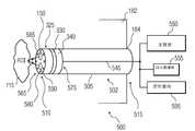
본 발명의 시스템의 다른 양태에 따르면, 신체 내부의 관심 영역의 3 차원 입체 이미지를 제공할 수 있는, 신체의 공동(cavity) 안으로 삽입되는 2 중 대물 렌즈 내시경(dual objective endoscope)이 제공되는데, 2 중 대물 렌즈 내시경은, 관심 영역으로부터의 제1 이미지 광선(ray)을 수광하기 위한 제1 렌즈를 가진 제1 구멍(bore); 관심 영역으로부터 제1 이미지 광선을 수광하기 위한 제2 렌즈를 가진 제2 구멍(bore); 레드, 그린 및 블루 광으로 관심 영역을 순차적으로 조명하기 위한 조명기들; 및, 단일 초점 어레이의 상이한 제1 영역 및 제2 영역상에 제1 이미지 광선 및 제2 이미지 광선의 이미지를 동시에 형성하기 위한 단일 초점 어레이를 포함하고, 각각 레드, 그린 및 블루 광들로써 3 번 순차 조명한 이후에 완전한 칼러 이미지가 수집된다. 더욱이, 레드, 그린 및 블루 광들을 제공하도록 적어도 하나의 광 안내부를 통하여 신체 외부의 적어도 하나의 광원으로 조명기들이 결합된다. 또한, 칼러 휘일의 회전시에 레드, 그린 및 블루 광들을 순차적으로 제공하기 위하여, 적어도 하나의 광원은 백색 광원 및, 레드, 그린 및 블루 필터들로 덮힌 3 개의 개구(opening)들을 가진 회전 칼러 휘일을 포함할 수 있다.According to another aspect of the system of the present invention, there is provided a dual objective endoscope inserted into a cavity of the body, which can provide a three-dimensional stereoscopic image of a region of interest inside the body. The medium objective lens endoscope includes a first bore having a first lens for receiving a first image ray from a region of interest; A second bore having a second lens for receiving a first image ray from the region of interest; Illuminators for sequentially illuminating the region of interest with red, green and blue light; And a single focal array for simultaneously forming an image of the first image beam and the second image beam on different first and second regions of the single focal array, sequentially three times with red, green and blue lights, respectively. After illumination, a full color image is collected. Moreover, the illuminators are coupled to at least one light source external to the body through the at least one light guide to provide red, green and blue lights. Also, in order to sequentially provide red, green and blue lights upon rotation of the color wheel, the at least one light source is a rotating color wheel with white openings and three openings covered with red, green and blue filters. It may include.
또한 적어도 하나의 광원은 레드, 그린 및 블루의 발광 다이오드(LED) 및, 레드, 그린 및 블루 광원들을 한번에 하나씩 순차적으로 켜기 위한 콘트롤러를 포함할 수 있다. 또한, 적어도 하나의 광 안내부는 레드, 그린 및 블루 필터들을 각각 가지는 3 개의 광 안내부들을 포함할 수 있고; 적어도 하나의 광원은 백색 광원 및 휘일을 포함할 수 있고; 그리고/또는 휘일이 개구를 가져서, 휘일이 회전할 때 3 개의 광 안내부들 중 하나의 광 안내부와 개구가 정렬시에, 개구는 백색광이 하나의 광 안내부를 통과하는 것을 허용함으로써, 휘일의 회전에 기인하여 3 개의 광 안내부들의 순차적인 조명을 제공한다.The at least one light source may include a red, green, and blue light emitting diode (LED) and a controller for sequentially turning on the red, green, and blue light sources one at a time. In addition, the at least one light guide may comprise three light guides each having red, green and blue filters; The at least one light source may comprise a white light source and a wheel; And / or the wheel has an opening so that when the opening is aligned with the light guide of one of the three light guides when the wheel rotates, the opening allows white light to pass through the one light guide, thereby rotating the wheel. Due to the sequential illumination of the three light guides.
또한 본 발명의 시스템의 다른 양태에 따르면, 의료용 이미지 시스템이 제공되는데, 의료용 이미지 시스템은, 기단 단부 및 말단 단부와, 기단 단부와 말단 단부 사이에 위치된 개구를 가지는 단단한 샤프트로서, 기단 단부와 말단 단부 사이에 연장된 길이 방향의 축을 형성하는, 샤프트; 기단 단부 및 말단 단부들을 가지고 개구 안에 위치된 로드(rod); 샤프트의 기단 단부에서 샤프트에 결합된 제1 및 제2 핸들로서, 제1 핸들 또는 제2 핸들 중 로드에 결합될 수 있는, 제1 및 제2 핸들; 제1 및 제2 핸들 중 하나를 향하는 제1 및 제2 핸들중 다른 하나의 변위가 이미지형성 부분(imaging portion)을 제2 축 둘레로 회전시키도록, 로드에 결합되고 샤프트의 말단 단부에 위치된 이미지 형성 부분;을 포함한다. 의료용 이미지 시스템은 이미지 부분에 결합된 2 차원 또는 3 차원 카메라를 더 포함할 수 있다. 또한, 이미지 부분은 카메라의 방향으로 조명을 제공하기 위한 조명원을 포함할 수 있다. 이미지 시스템은 로드의 말단 단부에 결합된 랙(rack)을 포함할 수 있고, 이미지 부분은 제2 축에 위치되고 랙에 결합된 피니언(pinion)을 더 포함할 수 있다.According to another aspect of the system of the present invention, there is also provided a medical imaging system, wherein the medical imaging system is a rigid shaft having a proximal end and a distal end and an opening located between the proximal end and the distal end, the proximal end and the distal end. A shaft defining a longitudinal axis extending between the ends; A rod positioned in the opening with proximal and distal ends; First and second handles coupled to the shaft at the proximal end of the shaft, the first and second handles being coupled to the rod, either the first handle or the second handle; Displacement of the other of the first and second handles facing one of the first and second handles is coupled to the rod and positioned at the distal end of the shaft to rotate the imaging portion about the second axis. And an image forming portion. The medical imaging system may further comprise a two-dimensional or three-dimensional camera coupled to the image portion. The image portion may also include an illumination source for providing illumination in the direction of the camera. The imaging system may include a rack coupled to the distal end of the rod, and the image portion may further include a pinion located on the second axis and coupled to the rack.
본 발명의 다른 시스템의 다른 양태에 따르면, 의료용 이미지 시스템이 제공되는데, 이것은 기단 단부 및 말단 단부와, 기단 단부와 말단 단부 사이에 위치된 개구를 가지는 단단한 샤프트로서, 기단 단부와 말단 단부 사이에 연장된 길이 방향 축을 형성하는, 샤프트; 기단 단부 및 말단 단부들을 가지고 개구 안에 위치된 로드(rod); 샤프트의 기단 단부에서 샤프트에 결합된 제1 및 제2 핸들로서, 제1 핸들 또는 제2 핸들 중 하나가 로드의 기단 단부에 결합되는, 제1 및 제2 핸들; 및/또는, 제1 및 제2 핸들 중 하나를 향하는 제1 및 제2 핸들 중 다른 하나의 변위가 카메라를 제2 축 둘레로 회전시키도록, 로드의 말단 단부에 결합되고 샤프트의 말단 단부에 위치된 이미지 형성 부분;을 포함한다.According to another aspect of another system of the present invention, a medical imaging system is provided, which is a rigid shaft having a proximal end and a distal end and an opening located between the proximal end and the distal end, extending between the proximal end and the distal end. A shaft, forming a longitudinal axis; A rod positioned in the opening with proximal and distal ends; First and second handles coupled to the shaft at the proximal end of the shaft, wherein one of the first handle or the second handle is coupled to the proximal end of the rod; And / or at the distal end of the shaft, coupled to the distal end of the rod, such that the displacement of the other of the first and second handles facing one of the first and second handles rotates the camera around the second axis. Includes an image forming portion.
2 차원 또는 3 차원 카메라는 이미지 부분에 결합될 수 있다. 더욱이, 이미지 부분은 카메라의 방향으로 조명을 제공하도록 조명 소스를 더 포함할 수 있다. 더욱이, 랙은 로드의 말단 단부에 결합될 수 있고, 랙은 복수개의 톱니(teeth)를 포함할 수 있다. 또한, 피니언은 랙에 결합될 수 있고 제2 축에 평행한 축을 가진다. 더욱이, 카메라는 제2 축 둘레에서 120 도 보다 크게 회전할 수 있는 시야 방향을 가질 수 있다. 따라서, 카메라는 단단한 샤프트의 길이 방향 축을 따라서 실질적으로 전방으로 또는 후방으로 돌출하는 시야 방향을 가질 수 있다.Two-dimensional or three-dimensional cameras can be coupled to the image portion. Moreover, the image portion may further comprise an illumination source to provide illumination in the direction of the camera. Moreover, the rack may be coupled to the distal end of the rod, and the rack may include a plurality of teeth. The pinion can also be coupled to the rack and has an axis parallel to the second axis. Moreover, the camera can have a viewing direction that can rotate greater than 120 degrees around the second axis. Thus, the camera may have a viewing direction that projects substantially forward or backward along the longitudinal axis of the rigid shaft.
본 발명의 다른 양태에 따르면, 3 차원(3D) 이미지를 획득하기 위한 내시경 시스템이 개시되는데, 내시경 시스템은, 이미지 조명 기간을 형성하는 복수개의 이미지 조명 간격들 중 각각의 이미지 조명 간격 동안에 상이한 칼러의 광이 통과되도록, 이미지 조명 간격 동안에 광의 복수개의 칼러 스펙트럼들 중 광의 상이한 칼러 스펙트럼을 순차적으로 통과시키는 다중 대역 통과 필터; 복수개의 이미지 조명 간격들 중 대응하는 이미지 조명 간격 동안에, 다중 대역 통과 필터를 통과하는 광의 상이한 칼러 스펙트럼에 각각 대응하는 복수개의 이미지들을 순차적으로 캡쳐(capture)하는 이미지 캡쳐부(capture portion); 각각의 이미지 조명 간격 동안 순차적으로 캡쳐된 복수개의 이미지들을 프로세싱(processing)하고, 순차적으로 캡쳐된 복수개의 이미지들에 대응하는 대응 3D 이미지 정보를 형성하는, 이미지 프로세싱부(processing portion); 및/또는, 3D 이미지 정보를 렌더링할 수 있는(rendering) 3 차원 디스플레이;를 포함한다.According to another aspect of the present invention, an endoscope system for acquiring a three-dimensional (3D) image is disclosed, wherein the endoscope system comprises a different color during each image illumination interval of a plurality of image illumination intervals forming an image illumination period. A multi-band pass filter that sequentially passes different color spectra of light among the plurality of color spectra of light during the image illumination interval so that light passes; An image capture portion for sequentially capturing a plurality of images each corresponding to a different color spectrum of light passing through the multi-band pass filter during a corresponding one of the plurality of image illumination intervals; An image processing portion for processing a plurality of images captured sequentially during each image illumination interval, and forming corresponding 3D image information corresponding to the plurality of images captured sequentially; And / or a three-dimensional display capable of rendering 3D image information.
더욱이, 광의 상이한 칼러 스펙트럼들이 복수개의 이미지 조명 간격들 중 임의의 2 개의 연속적인 이미지 조명 간격들 동안에 출력되도록, 내시경은 각각의 이미지 조명 간격 동안에 광의 상이한 칼러 스펙트럼을 순차적으로 출력하도록 구성된 적어도 하나의 소스를 포함하는 조명 장치를 구비할 수 있다. 또한, 조명 장치는. 모터 및/또는 디스크를 구비하며, 디스크는 적어도 하나의 다중 대역 통과 필터로 덮힌 하나 또는 그 이상의 개구를 가지며 모터에 결합되고, 모터는 각각의 이미지 조명 기간 또는 간격 동안에 광의 상이한 칼러 스펙트럼을 순차적으로 제공하도록 이미지 조명 기간에 역으로 비례하는 회전 주파수로 디스크를 회전시킨다.Moreover, the endoscope is configured to sequentially output different color spectra of light during each image illumination interval such that different color spectra of light are output during any two consecutive image illumination intervals of the plurality of image illumination intervals. It may be provided with a lighting device including a. In addition, the lighting device. Having a motor and / or a disk, the disk having one or more openings covered with at least one multi-band pass filter, coupled to the motor, the motor sequentially providing different color spectra of light during each image illumination period or interval. The disc is rotated at a rotation frequency which is inversely proportional to the image illumination period.
더욱이, 본 발명의 다른 양태에 따르면, 3 차원 이미지를 획득하기 위한 의료용 내시경 시스템이 개시되는데, 이것은, 이미지 조명 간격 동안에 광의 복수개의 칼러 스펙트럼들 중 광의 상이한 칼러 스펙트럼을 순차적으로 통과시키는 다중 대역 통과 필터; 다중 대역 통과 광학 필터를 통과하는 광의 상이한 칼러 스펙트럼에 각각 대응하는 복수개의 이미지들을 순차적으로 캡쳐(capture)하는 이미지 캡쳐 부; 각각의 이미지 조명 간격 동안 순차적으로 캡쳐된 복수개의 이미지들을 프로세싱(processing)하고, 대응 3D 이미지 정보를 형성하는, 이미지 프로세싱부; 및/또는, 3D 이미지 정보를 렌더링하는 3 차원 디스플레이;를 포함한다. 더욱이, 조명원이 포함될 수 있으며 조명원은 광의 상이한 칼러 스펙트럼들을 순차적으로 출력시키도록 구성될 수 있다. 다중 대역 통과 광학 필터는 동공(pupil)을 형성하는 하나 또는 그 이상의 개구를 가지는 디스크를 더 포함할 수 있다. 더욱이, 다중 대역 통과 필터는 내시경의 말단 단부에 위치될 수 있다.Moreover, according to another aspect of the present invention, a medical endoscope system for obtaining a three-dimensional image is disclosed, which is a multi-band pass filter that sequentially passes different color spectra of light among a plurality of color spectra of light during an image illumination interval. ; An image capture unit that sequentially captures a plurality of images each corresponding to a different color spectrum of light passing through the multi-band pass optical filter; An image processing unit for processing a plurality of images sequentially captured during each image illumination interval, and forming corresponding 3D image information; And / or a three-dimensional display for rendering the 3D image information. Moreover, an illumination source can be included and the illumination source can be configured to sequentially output different color spectra of light. The multiband pass optical filter may further comprise a disk having one or more openings forming a pupil. Moreover, a multi band pass filter can be located at the distal end of the endoscope.
본 발명의 시스템의 다른 양태에 따르면, 내시경으로부터 3 차원 이미지들을 획득하기 위한 방법이 개시되는데, 상기 방법은: 이미지 조명 기간을 형성하는 복수개의 이미지 조명 간격들 중 각각의 이미지 조명 간격 동안 광의 상이한 칼러가 다중 대역 통과 필터를 통과하도록, 이미지 조명 간격 동안 다중 대역 통과 필터를 통하여 광의 복수개의 칼러 스펙트럼들 중 광의 상이한 칼러 스펙트럼을 순차적으로 통과시키는 단계; 이미지 캡쳐부를 이용하여 복수개의 이미지 조명 간격들의 대응하는 이미지 조명 간격 동안 다중 대역 통과 필터를 통과하는 광의 상이한 칼러 스펙트럼에 각각 대응하는 복수개의 이미지들을 순차적으로 캡쳐하는 단계; 및, 이미지 프로세싱부를 이용하여, 각각의 이미지 조명 간격 동안 순차적으로 캡쳐된 복수개의 이미지들을 프로세싱하고, 순차적으로 캡쳐된 복수개의 이미지들에 대응하는 대응 3D 이미지 정보를 형성하는 단계; 및/또는 3 차원 이미지들을 디스플레이하도록 구성된 시스템의 디스플레이 상에 3D 이미지 정보를 렌더링하는(rendering) 단계를 포함한다. 또한, 상기 방법은 복수개의 이미지 조명 간격들의 임의의 2 개의 연속적인 이미지 조명 간격들 동안 광의 상이한 칼러 스펙트럼들이 출력되도록, 각각의 이미지 조명 간격 동안 광의 상이한 칼러 스펙트럼을 순차적으로 출력시키는 단계를 포함할 수 있다. 더욱이, 상기 방법은 각각 서로 상이한 광의 복수개의 칼러 스펙트럼들 중 광의 오직 현재 선택된 스펙트럼만을 통과시키도록 튜닝 가능한 다중 대역 통과 광학 필터를 선택적으로 제어하는 단계를 포함할 수 있다. 상기 방법은 2 개 또는 그 이상의 조명기, 다중 대역 통과 광학 필터 및, 이미지 캡쳐부를 서로 실질적으로 동기화시켜서 작동되게끔 이들을 동기화시키는 단계를 더 포함하여, 상이한 칼러 광들을 이용하여 관심 영역을 순차적으로 조명하고, 단일 이미지 장치 또는 단일 초점 평면 어레이(single Focal Plane Array; FPA) 상에 관심 영역의 상이한 칼러 이미지들을 순차적으로 형성한다.According to another aspect of the system of the present invention, a method for obtaining three-dimensional images from an endoscope is disclosed, which method comprises: different color of light during each image illumination interval of a plurality of image illumination intervals forming an image illumination period. Sequentially passing different color spectra of light of the plurality of color spectra of light through the multi-band pass filter during the image illumination interval such that the light passes through the multi-band pass filter; Capturing a plurality of images sequentially using an image capture portion respectively corresponding to different color spectra of light passing through the multi-band pass filter during the corresponding image illumination intervals of the plurality of image illumination intervals; And processing the plurality of images captured sequentially during each image illumination interval by using an image processing unit, and forming corresponding 3D image information corresponding to the plurality of images captured sequentially; And / or rendering 3D image information on a display of a system configured to display three-dimensional images. The method may also include sequentially outputting different color spectra of light during each image illumination interval such that different color spectra of light are output during any two consecutive image illumination intervals of the plurality of image illumination intervals. have. Moreover, the method may include selectively controlling a tunable multiband pass optical filter to pass only the currently selected spectrum of light of the plurality of color spectra of light each different from each other. The method further comprises synchronizing the two or more illuminators, the multi-band pass optical filter, and synchronizing the image capture portions to operate substantially in synchronism with each other, thereby sequentially illuminating the region of interest using different color lights. , Sequentially forming different color images of the region of interest on a single image device or single focal plane array (FPA).
본 발명의 시스템의 다른 양태에 따르면, 내시경으로부터 3 차원 이미지들을 획득하는 방법이 개시되는데, 상기 방법은: 다중 대역 통과 광학 필터를 이용하여 이미지 조명 간격 동안에, 광의 복수개의 칼러 스펙트럼들중 광의 상이한 칼러 스펙트럼을 순차적으로 통과시키는 단계; 이미지 캡쳐부를 이용하여 다중 대역 통과 광학 필터를 통과하는 광의 상이한 칼러 스펙트럼에 각각 대응하는 복수개의 이미지들을 순차적으로 캡쳐하는 단계; 이미지 프로세싱부를 이용하여, 각각의 이미지 조명 간격 동안 순차적으로 캡쳐된 복수개의 이미지들을 프로세싱하고, 이미지 프로세싱부를 이용하여 대응 3D 이미지 정보를 형성하는 단계; 및/또는, 3 차원 이미지들을 디스플레이하도록 구성된 시스템의 디스플레이상에 3D 이미지 정보를 나타내는 단계;를 포함한다. 본 발명의 방법은 내시경의 광학 렌즈 부분을 다중 대역 통과 광학 필터와 이미지 프로세싱부 사이에서 내시경의 단부에 있는 내시경의 말단 단부 및 내시경의 몸체 배럴(body barrel) 안에 위치시키는 단계를 더 포함할 수 있다. 더욱이, 본 발명의 방법은 기단 단부 및 말단 단부와, 말단 단부에서 4 mm 보다 작은 외측 직경을 가지는 내시경의 메인 몸체 배럴(main body barrel)을 형성하는 단계를 포함할 수 있다. 본 발명의 방법은 내시경의 말단 단부에 다중 대역 통과 필터를 위치시키는 단계를 더 포함할 수 있다.According to another aspect of the system of the present invention, a method of obtaining three-dimensional images from an endoscope is disclosed, which method comprises: a different color of light of a plurality of color spectra of light during an image illumination interval using a multi-band pass optical filter. Passing the spectra sequentially; Sequentially capturing a plurality of images each corresponding to a different color spectrum of light passing through the multi-band pass optical filter using an image capture unit; Processing an image captured sequentially during each image illumination interval using an image processing unit, and forming corresponding 3D image information using the image processing unit; And / or displaying 3D image information on a display of a system configured to display three-dimensional images. The method may further comprise positioning the optical lens portion of the endoscope in the body barrel of the endoscope and the distal end of the endoscope at the end of the endoscope between the multi-band pass optical filter and the image processing portion. . Furthermore, the method may comprise forming a main body barrel of an endoscope having a proximal end and a distal end and an outer diameter of less than 4 mm at the distal end. The method may further comprise placing a multi-band pass filter at the distal end of the endoscope.
본 발명은 첨부된 도면을 참조하여 예를 들어 더욱 상세하게 설명될 것이다.
도 1a 는 본 발명의 시스템의 실시예에 따른 2 중 대물 렌즈 내시경의 측부 단면도이다.
도 1b 는 FPA 의 정면도를 도시하는 도 1a 의 선 1B-1B' 를 따라서 취한 내시경의 단면도이다.
도 1c 는 본 발명의 시스템의 실시예에 따른 FPA 의 정면도를 도시한다.
도 1d 는 본 발명의 시스템의 실시예에 따른 내시경의 정면도이다.
도 2a 는 본 발명의 시스템의 실시예에 따라서 LED 광원을 이용하는 시스템의 개략적인 도면이다.
도 2b 는 본 발명의 시스템의 실시예에 따라서 백색 광원을 이용하는 시스템의 개략적인 도면이다.
도 2c 는 본 발명의 시스템의 실시예에 따라서 백색 광원을 이용하는 시스템의 개략적인 도면이다.
도 3a 는 본 발명의 시스템의 실시예에 따른 이미지 유닛의 사시도이다.
도 3b 는 본 발명의 시스템의 실시예에 따른 콤팩트 이미지 유닛의 사시도이다.
도 3c 는 본 발명의 시스템의 실시예에 따른 접힘 이미저(folded imager)를 가지는 이미지 장치를 구비하는 내시경의 개략적인 도면이다.
도 3d 는 본 발명의 시스템의 실시예에 따른 대안의 이미지 장치를 포함하는 내시경의 개략적인 도면이다.
도 4a 는 본 발명의 시스템의 실시예에 따른 내시경의 개략적인 도면이다.
도 4b 는 본 발명의 시스템의 실시예에 따른 내시경의 정면도이다.
도 5 는 본 발명의 시스템의 실시예에 따른 내시경 시스템의 개략적인 도면이다.
도 6 은 본 발명의 시스템의 실시예에 따른 내시경의 정면도이다.
도 7a 는 본 발명의 시스템의 실시예에 따른 내시경의 이미지 장치 구성부에 대한 개략적인 도면이다.
도 7b 는 본 발명의 시스템의 실시예에 따른 반원형의 우측 및 좌측 복합 다중 대역 통과 필터들(CMBFs)을 도시하는 내시경의 정면도이다.
도 8 은 본 발명의 시스템의 실시예에 따른 내시경의 조명원의 개략적인 도면이다.
도 9 는 본 발명의 시스템의 실시예에 따른 다중 대역 통과 필터의 통과 대역 및 저지 대역(stop band)을 도시하는 그래프이다.
도 10a 는 본 발명의 시스템의 실시예에 따른 시스템의 개략적인 도면이다.
도 10b 는 본 발명의 시스템의 실시예에 따른 시스템의 개략적인 도면이다.
도 10c 는 본 발명의 실시예에 따른 제1 내지 제3 통공들을 통과하는 칼러들의 그래프이다.
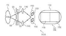
도 11a 는 본 발명의 시스템의 실시예에 따른 단일 렌즈를 가진 내시경을 구비한 이미지 시스템을 나타낸다.
도 11b 는 본 발명의 시스템의 실시예에 따른 2 중 렌즈 구성의 내시경을 가진 이미지 시스템을 나타낸다.
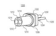
도 12a 는 본 발명의 시스템의 실시예에 따른 입체 이미지 시스템의 전방 사시도를 나타낸다.
도 12b 는 본 발명의 시스템의 실시예에 따른 도 12a 의 입체 이미지 시스템의 후방 사시도를 도시한다.
도 13 은 본 발명의 시스템의 실시예에 따른 입체 이미지 장치를 도시한다.
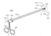
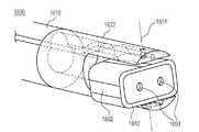
도 14 는 본 발명의 시스템의 실시예에 따른 내시경을 도시한다.
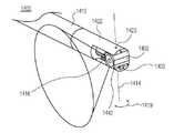
도 15 는 본 발명의 시스템의 실시예에 따른 내시경의 말단 단부 부분의 상세도이다.
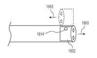
도 16 은 본 발명의 시스템의 실시예에 따른 내시경의 말단 단부 부분의 상세도이다.
도 17 은 본 발명의 시스템의 실시예에 따른 내시경의 카메라 부분의 상세도이다.
도 18a 및 도 18b 는 본 발명의 시스템의 실시예에 따른 내시경의 말단 단부 부분의 상세도이다.
도 19 는 본 발명의 시스템의 실시예에 따른 프로세스를 도시하는 흐름도이다.
도 20 은 본 발명의 시스템의 실시예에 따른 시스템(예를 들면, 피어(peer), 서버(server)등)의 일부를 도시한다.The invention will be explained in more detail by way of example with reference to the accompanying drawings.
1A is a side cross-sectional view of a dual objective lens endoscope in accordance with an embodiment of the system of the present invention.
FIG. 1B is a cross-sectional view of the endoscope taken along
1C shows a front view of an FPA in accordance with an embodiment of the system of the present invention.
1D is a front view of an endoscope in accordance with an embodiment of the system of the present invention.
2A is a schematic diagram of a system using an LED light source in accordance with an embodiment of the system of the present invention.
2B is a schematic diagram of a system using a white light source in accordance with an embodiment of the system of the present invention.
2C is a schematic diagram of a system using a white light source in accordance with an embodiment of the system of the present invention.
3A is a perspective view of an image unit in accordance with an embodiment of the system of the present invention.
3B is a perspective view of a compact image unit in accordance with an embodiment of the system of the present invention.
3C is a schematic diagram of an endoscope having an imaging device having a folded imager according to an embodiment of the system of the present invention.
3D is a schematic diagram of an endoscope including an alternative imaging device in accordance with an embodiment of the system of the present invention.
4A is a schematic diagram of an endoscope in accordance with an embodiment of the system of the present invention.
4B is a front view of an endoscope in accordance with an embodiment of the system of the present invention.
5 is a schematic diagram of an endoscope system according to an embodiment of the system of the present invention.
6 is a front view of an endoscope in accordance with an embodiment of the system of the present invention.
7A is a schematic diagram of an imaging device component of an endoscope according to an embodiment of the system of the present invention.
7B is a front view of an endoscope showing semicircular right and left complex multiband pass filters (CMBFs) in accordance with an embodiment of the system of the present invention.
8 is a schematic diagram of an illumination source of an endoscope according to an embodiment of the system of the present invention.
9 is a graph illustrating the pass band and stop band of a multi-band pass filter in accordance with an embodiment of the system of the present invention.
10A is a schematic diagram of a system according to an embodiment of the system of the present invention.
10B is a schematic diagram of a system according to an embodiment of the system of the present invention.
10C is a graph of collars passing through the first through third through holes according to an embodiment of the present invention.
11A illustrates an imaging system with an endoscope with a single lens in accordance with an embodiment of the system of the present invention.
11B illustrates an imaging system with an endoscope in a dual lens configuration according to an embodiment of the system of the present invention.
12A shows a front perspective view of a stereoscopic imaging system according to an embodiment of the system of the present invention.
12B shows a rear perspective view of the stereoscopic imaging system of FIG. 12A in accordance with an embodiment of the system of the present invention.
Figure 13 illustrates a stereoscopic imaging device according to an embodiment of the system of the present invention.
14 illustrates an endoscope in accordance with an embodiment of the system of the present invention.
15 is a detailed view of the distal end portion of an endoscope in accordance with an embodiment of the system of the present invention.
16 is a detailed view of the distal end portion of an endoscope in accordance with an embodiment of the system of the present invention.
17 is a detailed view of a camera portion of an endoscope in accordance with an embodiment of the system of the present invention.
18A and 18B are detailed views of distal end portions of an endoscope in accordance with an embodiment of the system of the present invention.
19 is a flowchart illustrating a process according to an embodiment of the system of the present invention.
20 illustrates a portion of a system (eg, peer, server, etc.) in accordance with an embodiment of the system of the present invention.
하기는 상기에 언급된 특징들 및 장점들뿐만 아니라 다른 특징들 및 장점들을 나타낼 예시적인 실시예들을 첨부된 도면을 참조하여 설명한 것이다. 하기 설명에서는 발명을 제한하기보다는 설명하기 위한 목적으로, 구조, 인터페이스, 테크닉, 구성요소의 특성 등과 같은 예시적이고 상세한 내용들이 설명될 것이다. 그러나, 그러한 상세한 내용 범위를 벗어나지 않는 한 다른 실시예들 또한 첨부된 청구항의 범위 내에서 여전히 이해될 수 있음이 당업자에게 명백할 것이다. 더욱이, 명확성을 위하여, 본 발명의 시스템의 설명을 모호하게 하지 않도록 공지된 장치, 회로, 툴(tool), 기술 및 방법들에 대한 상세한 설명은 생략된다. 도면은 예시적인 목적을 위해서만 제시된 것이며 본 발명의 시스템의 범위를 제한하지 않는다는 점이 명백히 이해되어야 한다. 첨부된 도면에서, 상이한 도면들에 있는 동일한 참조 번호는 동일한 구성요소들을 나타낼 수 있다.The following describes exemplary embodiments with reference to the above-mentioned features and advantages as well as other features and advantages with reference to the accompanying drawings. In the following description, for purposes of explanation rather than limitation, exemplary and detailed descriptions, such as structures, interfaces, techniques, characteristics of components, and the like, will be described. However, it will be apparent to one skilled in the art that other embodiments may still be understood within the scope of the appended claims without departing from the scope of such details. Moreover, for the sake of clarity, detailed descriptions of well-known devices, circuits, tools, techniques and methods are omitted so as not to obscure the description of the system of the present invention. It is to be understood that the drawings are presented for illustrative purposes only and do not limit the scope of the system of the present invention. In the accompanying drawings, the same reference numerals in different drawings may represent the same components.
본원에서 사용되는 바로서, 내시경(endoscope)이라는 용어는 감싸인 부위를 관찰하기 위한 의료용 관찰 기계를 지칭할 것이며, 예를 들어, 복강경, 산업용 내시경, 기관지경, 결장 내시경, 콜레도쇼스코프(choledoshoscope), 십이지장경, 에코엔도스코프(echoendoscope), 장내시경, 식도경, 위경, 후두경, 비후두경, S 결장경 및/또는 다른 유사한 이미지 장치와 같은 것을 지칭할 것이다. 또한, 여기에 설명된 분광학적 카메라(예를 들어, 이미지 촬상) 부분은 예를 들어 우주, 항공, 육상 및/또는 물속의 환경에서, 항공기, 우주 탐사, 원격 제어(예를 들어, 무인) 선박, 로봇 등과 같은 차량에서 사용될 수 있다. 또한, 그러한 차량들의 원격 네비게이션 성능을 제공하기 위하여 네비게이션 시스템이 본 발명의 시스템과 인터페이스(interface)될 수 있다. 분광학적 3D 카메라를 포함하는 본 발명의 시스템은 다양하게 상기 언급된 것 및 다른 시스템과 소형의 구성들에 통합되고 그리고/또는 결합됨으로써 분광학적 3D 이미지를 제공하는데, 그것은 예를 들어 목적물의 원격 네비게이션, 이미지 촬상 및 탐사를 위하여 분광학적 3D 카메라에 의해 캡쳐된 이미지들의 깊이 인식(depth perception)을 포함하며, 상기 목적물은 소형 목적물 및/또는 목적물에 있는 작은 틈새, 개구, 채널을 포함하고, 목적물은 인간의 신체, 생물 및/또는 무생물인가에 무관하게 그 어떤 유형의 몸체일 수 있다.As used herein, the term endoscope will refer to a medical observation machine for observing the enclosed area, for example, laparoscopy, industrial endoscopes, bronchoscopes, colonoscopy, choledoshoscopes. ), Duodenum, echoendoscope, intestinal endoscopy, esophagus, gastroscopy, laryngoscope, nasopharyngoscope, S colonoscope and / or other similar imaging device. In addition, the spectroscopic camera (e.g., image imaging) portion described herein may be used in aircraft, space exploration, remote control (e.g., unmanned) ships, for example in space, aviation, land and / or underwater environments. Can be used in vehicles such as robots, and the like. In addition, a navigation system may be interfaced with the system of the present invention to provide remote navigation performance of such vehicles. The system of the present invention, including a spectroscopic 3D camera, provides a spectroscopic 3D image by being integrated and / or combined in various configurations with those mentioned above and other systems and compact configurations, which are for example remote navigation of the object. Depth perception of the images captured by the spectroscopic 3D camera for image capture and exploration, the object comprising a small object and / or small gaps, openings, channels in the object, the object being It may be any type of body, regardless of whether it is a human body, a creature, and / or an inanimate object.
본 발명의 시스템의 설명을 단순화하기 위한 목적으로, 여기에서 사용되는 "작동되게 결합되는(operatively coupled)", "결합되는(coupled)" 용어 및 이들의 파생어들은 장치들 및/또는 장치의 부분들 사이의 연결을 지칭하며, 그 연결은 본 발명의 시스템에 따른 작동을 가능하게 한다. 예를 들어, 작동 결합은 2 개 또는 그 이상의 장치들 사이에서의 하나 또는 그 이상의 유선(wired) 연결 및/또는 무선(wireless) 연결을 포함할 수 있고, 그러한 연결은 장치들 및 그 장치들의 부분들 사이에서 1 방향 및/또는 2 방향 통신 경로를 가능하게 한다. 예를 들어, 작동 결합은 콘텐트 서버(content server)(예를 들어, 검색 엔진 등)와 하나 또는 그 이상의 사용자 장치들 사이에서 통신을 가능하게 하는 와이어 결합 및/또는 와이어리스 결합을 포함할 수 있다. 본 발명의 시스템의 실시예에 따른 다른 작동 결합은 2 개 또는 그 이상의 사용자 장치들 사이에서, 직접적으로 또는 콘텐트 서버와 같은 네트워크 소스(network source)를 통한 하나 또는 그 이상의 결합을 포함할 수 있다.For the purpose of simplifying the description of the system of the present invention, the terms "operatively coupled", "coupled" and derivatives thereof used herein are devices and / or parts of the devices. Refers to the connection between, enabling the operation according to the system of the present invention. For example, operative coupling may include one or more wired connections and / or wireless connections between two or more devices, which connection may comprise devices and portions of the devices. Enable one-way and / or two-way communication paths between them. For example, the operational coupling may include wire coupling and / or wireless coupling to enable communication between a content server (eg, a search engine, etc.) and one or more user devices. Another operational coupling according to an embodiment of the system of the present invention may include one or more couplings between two or more user devices, either directly or through a network source such as a content server.
본원에서 사용되는 용어 렌더링(rendering) 및 이들의 파생어들은 디지털 매체와 같은 콘텐트를 제공하는 것을 지칭하는데, 상기 디지탈 매체는 예를 들어 청각 정보, 시각 정보, 시청각 정보 등을 포함할 수 있어서, 시각 및/또는 청각과 같은 적어도 하나의 사용자 감각에 의해 인식될 수 있다. 예를 들어, 본 발명의 시스템은 디스플레이 장치 상에 사용자 인터페이스(user interface;UI)를 렌더링하여 사용자가 그것을 볼 수 있고 사용자에 의해 상호작용할 수 있다. 또한 본 발명의 시스템은 가청 출력(예를 들어, 확성기와 같은 스피커)을 렌더링하는 장치 및, 가시 출력(예를 들어, 디스플레이)을 렌더링하는 장치 양쪽에 시청각 콘텐트를 렌더링할 수 있다. 다음의 설명을 단순화시키기 위하여, 용이하게 이해될 수 있게 특정의 콘텐트 유형이 특정적으로 의도되지 않는 한, 콘텐트(content)라는 용어 및 이들의 파생어들은 청각 콘텐트, 시각 콘텐트, 시청각 콘텐트 및/또는 다른 콘텐트 유형을 포함하도록 이용될 것이고 그렇게 이해되어야 한다.As used herein, the term rendering and its derivatives refer to providing content, such as digital media, which may include, for example, audio information, visual information, audiovisual information, and the like. And / or at least one user's senses, such as hearing. For example, the system of the present invention renders a user interface (UI) on a display device so that the user can see it and interact with it. The system of the present invention can also render audiovisual content to both devices that render an audible output (eg, a loudspeaker, such as a loudspeaker), and devices that render visible output (eg, a display). To simplify the following description, the term content and its derivatives refer to auditory content, visual content, audiovisual content, and / or other, unless a particular content type is specifically intended to be readily understood. It will be used to include the content type and should be understood as such.
사용자가 컴퓨터 환경의 조작과 상호 작용하는 것은, 디스플레이 환경을 제어하는 프로세서(예를 들어, 콘트롤러, 논리 장치(logic device) 등) 또는 프로세서들에 작동되게 결합된 임의의 다양한 유형의 인간-프로세서 인터페이스 장치들을 이용하여 달성될 수 있다. 시스템은 단독으로 작동될 수 있거나, 또는 시스템의 디스플레이 상에 렌더링될 수 있는 그래픽 사용자 인터페이스(graphical user interface, GUI)와 같은 사용자 인터페이스에 따라서 작동될 수 있다. 디스플레이는 2 차원 또는 3 차원의 디스플레이를 포함할 수 있다.The user's interaction with the manipulation of the computer environment may include any of a variety of types of human-processor interfaces operatively coupled to the processor (eg, controller, logic device, etc.) or processors that control the display environment. Can be achieved using devices. The system can be operated alone or in accordance with a user interface such as a graphical user interface (GUI) that can be rendered on the system's display. The display can include a two-dimensional or three-dimensional display.
본 발명의 시스템에 따른 입체(stereoscopic) 내시경은, 통상적인 내시경의 기단 단부에 있는 접안부(eyepiece)로 광학 이미지를 릴레이(relay)하거나 또는 이미저(imager)에 이미지들을 형성하도록 통상적으로 이용되는 릴레이 렌즈 및/또는 렌티큘라 렌즈 어레이(lenticular lens array)들을 이용하지 않으면서, 단일의 초점 평면 어레이(Focal Plane Array;FPA)상에 직접적으로 서브 이미지(sub-image)를 투사하고 형성하는 (단일의 구멍(bore) 및/또는 다수의 구멍들의 말단 단부에 있는) 하나 또는 그 이상의 대물 렌즈들을 덮고 그리고/또는 그것과 통합되는 복합 다중 대역 통과 필터(Conjugated Multi-Bandpass Filters;CMBSs)를 포함한다. 본 발명의 시스템에 따른 내시경의 말단 단부에 있는 FPA 에 의해 캡쳐된 광학적 서브 이미지는 3D 이미지 및/또는 서브 이미지 데이타/정보를 형성하도록 처리되는데, 그것은 예를 들어 서브 이미지 데이타의 (예를 들어 3 또는 6 개) 세트로부터 3D 이미지 데이타를 형성하도록 프로세서에 의한 처리를 위한, 예를 들어 아날로드-디지털(A/D) 변환기에 의하여, 광학 이미지들 및/또는 서브 이미지들을 디지털 형태로 변환시킴으로써 이루어진다.Stereoscopic endoscopes according to the system of the present invention are relays commonly used to relay optical images to or form images on an imager with an eyepiece at the proximal end of a conventional endoscope. Project and form a sub-image directly onto a single focal plane array (FPA) without the use of lenses and / or lenticular lens arrays (single Conjugated Multi-Bandpass Filters (CMBSs) covering and / or integrated with one or more objective lenses (bore) and / or at the distal end of the plurality of holes. Optical sub-images captured by the FPA at the distal end of the endoscope according to the system of the present invention are processed to form 3D images and / or sub-image data / information, for example of sub-image data (eg 3 Or by converting optical images and / or sub-images into digital form, for example by an analog-to-digital (A / D) converter, for processing by a processor to form 3D image data from a set of six). .
통상적인 내시경 및 산업용 내시경과는 다르게, 본 발명의 시스템의 실시예에 따른 내시경들은 렌티큘라 렌즈 부분(lenticular lens portion)에 대한 필요성이 없으며, 렌티큘라 렌즈 부분 없이 단일의 FPA 상에 직접적으로 우측 및 좌측 이미지를 투사한다. 따라서, 본 발명의 시스템에 따른 내시경은 렌티큘라 렌즈 또는 렌즈 어레이들에 대한 필요성 없이 대물 렌즈 시스템으로부터 FPA 로 이미지를 제공한다. 더욱이, 대물 렌즈 시스템 및 FPA 양쪽은 내시경의 말단 단부에 위치될 수 있고 관심 영역을 관찰하기 위하여몸체 내부에 삽입될 수 있다. 집적 실리콘 온 칩(Integrated Silicon on Chip:ISOC substrate)과 같은 반도체 기판 안에/위에 형성된 집적 회로도 예를 들어 내시경의 말단 단부에 포함될 수 있다.Unlike conventional endoscopes and industrial endoscopes, endoscopes according to an embodiment of the system of the present invention eliminate the need for a lenticular lens portion, and directly to the right and right on a single FPA without the lenticular lens portion. Project the left image. Thus, the endoscope according to the system of the present invention provides an image from the objective lens system to the FPA without the need for lenticular lenses or lens arrays. Moreover, both the objective lens system and the FPA can be located at the distal end of the endoscope and insertedinside thebody to observe the region of interest. Integrated circuits formed in / on a semiconductor substrate, such as an Integrated Silicon on Chip (ISOC substrate), may also be included, for example, at the terminal end of the endoscope.
도 1a 는 본 발명의 시스템의 실시예에 따른 2 중 대물 렌즈 내시경(100)의 측부 단면도이다. 내시경(100)은 제1 및 제2 서브 유닛(102,104)을 포함할 수 있으며, 제1 및 제2 서브 유닛은 서로 동일할 수 있고 서로 가깝게 위치될 수 있다. 제1 서브 유닛(102)은 우측 이미지를 유지할 수 있고, 제2 서브 유닛(104)은 좌측 이미지를 유지할 수 있다. 도 1a 에 도시된 바와 같이, 2 중 대물 렌즈 내시경(100)은 ROI(115)로부터 제1 이미지 광선(image ray, 114)을 수광하기 위한 제1 렌즈(112)를 가진 제1 구멍(110) 및, ROI(115)로부터 제2 이미지 광선(124)을 수광하기 위한 제2 렌즈(122)를 가진 제2 구멍(120)을 포함한다. 제1 및 제2 렌즈(112,122)들은 몇개의 렌즈들을 각각 포함할 수 있는데, 예를 들어 이미지 광선(114,124)을 집속시키기 위한 대물 렌즈(112,122) 및 집속된 이미지 광선(114,124)들을 단일의 초점 평면 어레이(PFA)(130)상에 초점을 맞추는 초점 렌즈(116,126)와 같은 것을 포함한다. 광원 또는 조명기(150)(도 1d)들이 레드, 그린 및 블루의 광과 같은 상이한 칼러의 광들로써 관심 영역(115)을 순차적으로 조명할 수 있다. 제1 서브 유닛(102)은 제1 구멍(110) 안에 위치될 수 있고, 제2 서브 유닛(104)은 제2 구멍(120) 안에 위치될 수 있다. 제1 및 제2 구멍(110,120)들은 말단 단부(170) 및 기단 단부(180)를 가지는 몸체(165)의 메인 내강(160) 안에 위치될 수 있다. 따라서, 우측 이미지를 유지/투사하는 내시경의 부분들은 우측 이미지 채널로서 알려져 있고, 좌측 이미지를 운반/투사하는 내시경의 부분들은 좌측 이미지 채널로서 알려질 수 있다. 사용중에, 내시경(100)의 말단 단부(170)는 통상적으로 신체의 공동(cavity) 또는 개구(184)를 통하여 신체(182) 내로 삽입되는 반면에, 기단 단부(180)는 신체의 밖에 남는다. 신체(182)는 목적물 내부의 관찰이 필요한 임의의 무생물 목적물의 몸체뿐만 아니라, 환자, 인간 또는 다른 것의 신체일 수 있다.1A is a side cross-sectional view of a dual
렌즈(112,122)들은 FPA(130)의 상이한 (우측 및 좌측) 영역(132,134)들에서 제1/우측 및 제2/좌측 이미지 광선(114,124)들을 각각 동시에 이미지로 만들기 위해서 관심 영역(115)으로부터 반사된 광을 동시에 수광할 수 있다. 시간-순차 조명(time-sequential illumination)이 RGB 광을 한번에 하나씩 제공할 때, 3 번의 시퀀스 이후에, 완전한 칼러 이미지가 FPA(130) 상에 모인다. 예를 들어, 도 1b-도 1d 와 관련하여 설명된 바와 같이, 3 개의 (예를 들어 RGB) 우측 이미지들은 우측 영역(132)상에 순차적으로 중첩될 수 있고, 동시에 2 개의 (RGB) 좌측 이미지들은 좌측 영역(134)상에 순차적으로 중첩될 수 있다. 따라서, 본 발명의 실시예에서, 3 개의 이미지들은 완전한 칼러 이미지를 형성하도록 캡쳐될 수 있다. 그러나, 도 7a-7b 와 관련하여 아래에 설명되는 바와 같은 셔터(shutter)를 포함하는 실시예에서, 6 개의 이미지들이 완전한 칼러 이미지를 얻는데 필요할 수 있다.The
도 1b 는 도 1a 의 선 1B-1B' 를 따라서 취한 내시경(100)의 도면으로서, 이것은 FPA(130)의 정면도를 나타낸다. FPA(130)의 우측 이미지 영역(132)은 제1/우측 이미지 광선(투사)(144)을 캡쳐(capture)하고, FPA(130)의 좌측 이미지 영역(134)은 제2/좌측 이미지 광선(투사)(124)을 캡쳐한다 비록 둥근 FPA(130) 및 정사각형의 이미지 영역(132,134)들이 도시되었을지라도, FPA(130) 및 이미지 영역(132,134)들은 타원형 및/또는 직사각형 형상 유형등과 같은 다른 형상 및/또는 크기를 포함할 수 있고, 여기에서 FPA(130) 및 이미지 영역(132,134)들이 동일하거나 또는 상이한 형상의 유형을 가질 수 있다. 예를 들어, 도 1c 는 본 발명의 시스템의 다른 실시예에 따른 타원형 FPA(130')의 정면도를 도시한다. FPA(130')는 정사각형 (또는 둥글거나 또는 임의의 소망 형상) 우측 이미지 영역(132') 및 좌측 이미지 영역(134')을 포함하며, 이것은 도 1b 에 도시된 FPA(130)의 우측 이미지 영역(132) 및 좌측 이미지 영역(134)에 각각 대응한다.FIG. 1B is a diagram of the
도 1d 는 우측 대물 렌즈(112) 및 좌측 대물 렌즈(122)를 포함하는 이미지 유닛(190)을 나타내는, 도 1a 의 선 1D-1D' 를 따르는 내시경(100)의 정면도로서, 여기에서 양쪽 렌즈(112,114)들은 동시에 조명기(150)로부터 조사되고 ROI(405)로부터 반사된 광을 수광한다. 조명기(150)는 이미지 유닛(190)의 주위 둘레에 배치될 수 있고 상이한 파장의 상이한 광을 (예를 들어 콘트롤러 또는 프로세서의 제어하에) 순차적으로 제공함으로써, (예를 들어 RGB 스펙트럼에 대응하는) 칼러들을 한번에 하나씩 제공하도록 구성될 수 있다. 예를 들어, 시간(t1)에, 조명기(150)들은 레드 광을 제공할 수 있고, 그에 응답하여 레드의 우측 이미지 및 좌측 이미지가 (도 1a-1b 에 도시된) FPA(130)의 우측 이미지 영역(132) 및 좌측 이미지 영역(134)에 동시에 캡쳐될 수 있다. 다음에, 시간(t2)과 같은 나중의 시간에, 조명기(150)들은 그린 광을 제공할 수 있고, 그린의 우측 이미지 및 좌측 이미지가 FPA(130)의 우측 이미지 영역(132) 및 좌측 이미지 영역(134)에서 동시에 캡쳐될 수 있다. 다음에, t3 와 같은 나중의 시간에, 조명기(150)는 블루 광을 제공할 수 있고, 블루의 우측 이미지 및 좌측 이미지가 FPA(130)의 우측 이미지 영역(132) 및 좌측 이미지 영역(134)상에 동시에 캡쳐될 수 있다. 다음에 시스템은 시스템의 디스플레이상에 표시될 수 있는 완전한 칼러의 3 차원 이미지를 형성하기 위하여, 캡쳐된 그린 및 블루의 우측 및 좌측 이미지(예를 들어, 시간 t2 및 t3 에 캡쳐된 것)에 대한 정보를 캡쳐된 레드의 우측 및 좌측 이미지들(예를 들어, 시간 t1 에 캡쳐된 것)에 중첩시킬 수 있다. 따라서, 시간 t3 이후에, (예를 들어, 레드, 그린 및 블루 광의) 조명의 3 개 시퀀스들 이후에, 집적된 실리콘 온 칩(Integrated Silicon on Chip (ISOC)) 에 의한 더 이상의 처리를 위하여 완전 칼러 이미지가 우측 및 좌측 이미지 영역(132,134)들에 의해 캡쳐될 수 있다. 따라서, FPA(130)의 우측 및 좌측 이미지 영역(132,134)의 각각으로부터의 3 개 이미지들은 각각 완전한 칼러 이미지를 형성하도록 처리될 수 있으며, 여기에서 우측 이미지는 FPA(130)의 우측 이미지 영역(132)에서 형성되고, 좌측 이미지는 FPA(130)의 좌측 이미지 영역(134)에서 형성된다. 프로세서는 3 개의 우측 및 좌측 이미지들을 상호 관련시키고 조합하여 입체 이미지 및/또는 3D 이미지를 형성한다.FIG. 1D is a front view of the
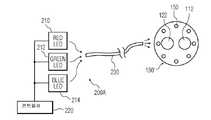
레드, 그린 및 블루 광을 가지고 (예를 들어 한번에 하나씩) 순차적으로 조명하는 것은, 발광 다이오드(LEDs), 제논 광원등에 의한 것과 같이 임의의 적절한 광을 이용하여 제공될 수 있다. 예를 들어, 도 2a 는 본 발명의 시스템의 실시예에 따른 LED 광원을 이용하는 시스템(200A)의 개략적인 도면이다. 시스템(200A)은 레드, 그린 및 블루 LED (210,212,214)를 각각 가진 내시경(예를 들어, 이미지 유닛(190')을 가진 정면으로부터 도시된 내시경)을 포함할 수 있으며, 이들 LED 는 대응하는 광(예를 들어, 레드, 그린 및 블루)을 광 채널(230)을 통하여 이미지 유닛(190')의 조명기(150)로 제공한다. 광 채널(230)은 광섬유 광채널, 아크릴 광채널(acrylic light channel)등과 같은 임의의 적절한 도광 채널(light conducting channel)을 포함할 수 있다.Illuminating sequentially with red, green, and blue light (eg, one at a time) may be provided using any suitable light, such as with light emitting diodes (LEDs), xenon light sources, and the like. For example, FIG. 2A is a schematic diagram of a
일 실시예에서, 광 채널(230)은 예를 들어 도 1d, 도 2a-2c 및 도 10a-10b 와 같은 다양한 실시예들의 다양한 도면들에 도시된 조명기(150)를 통하는 것과 같이, 광섬유의 말단 또는 출구 단부(들)를 통하여 배출되는 광으로부터 ROI(115)를직접적으로 조명하도록 하나 또는 그 이상의 광섬유를 포함한다. 다른 실시예에서, 직접 조명 대신에, 도 16 과 관련하여 설명될 하나 또는 그 이상의 페리스코프(periscope)들과 같은, 하나 또는 그 이상의 인터페이스 유닛들은, 예를 들어 적어도 하나의 광섬유 케이블과 같은, 광 안내부(들)의 말단 단부(들)로부터, 광을 수광할 수 있다. 페리스코프(들)는 광을 광 배출 유닛으로 지향시키고, 예를 들어 반사시키는데, 광 배출 유닛은 우측 및 좌측 동공(pupil)의 둘레에 위치되며 광을 외부로 지향시켜서 ROI(115)를 조명한다.In one embodiment, the
광 채널(230)은 커플러 부분(coupler portion) 및 디커플러 부분(decoupler portion)을 구비할 수도 있는데, 커플러 부분은 LED(210,212 및/또는 214)를 광 채널(230)에 결합시킬 수 있고, 디커플러 부분은 광 채널(230)을 조명기(150)로 결합시킬 수 있다. LED(210,212 및/또는 214)는 단색광을 조사할 수 있고 콘트롤러(220)의 제어하에 한번에 하나씩 순차적으로 켜질 수 있다. 콘트롤러(220) 및/또는 LED(210,212 및/또는 214)는 예를 들어 내시경(100)의 기단 단부(180)(도 1a)에 위치되거나 또는 연결될 수 있어서, LED 에 의해 제공되는 광은 광섬유(들)와 같은 광 안내부(들) 또는 광 채널(들)을 통하여 내시경(100)의 말단 단부에 있는 이미지 유닛(190')의 조명기(150)로 전달될 수 있다.The
도 2b 는 본 발명의 시스템의 다른 실시예에 따른 백색 광원(235)을 이용하는 시스템(200B)의 개략적인 도면이다. 백색 광원(235)은 백색 스펙트럼과 같은 스펙트럼 또는 소망의 스펙트럼에 대응하는 광을 조사하는 적절한 광원을 포함할 수 있다. 필터(237)와 같은 필터가 콘트롤러(220)에 의해 오직 소망되는 광의 파장(또는 주파수 등)만을 통과시키도록 구비될 수 있다. 필터(237)는 고체 상태 및/또는 아날로그 필터를 구비할 수 있다. 예를 들어, 필터(237)는 레드, 그린 및 블루 필터(250,252,254)로 각각 덮힌 3 개의 개구들을 가진 회전 칼러 휘일(240)을 구비할 수 있다. (예를 들어, 소망의 회전 주파수(ω))에서 콘트롤러(220)의 제어하에 스테퍼 모터와 같은 모터(248)에 의하여) 칼러 휘일(240)이 회전되면, 필터는 한번에 광 채널(230)을 통하여 조명기(150)로 광의 단일 칼러를 순차적으로 통과시킬 수 있다.2B is a schematic diagram of a
도 2c 는 본 발명의 시스템의 실시예에 따른 백색 광원(235)을 이용하는 시스템(200C)의 개략적인 도면이다. 시스템(200C)은 시스템(200B)과 유사할 수 있다. 그러나, 시스템(200C)은 회전 휘일(280)을 구비할 수 있으며, 회전 휘일은 (시스템(200B)의 회전 휘일(240)의 3 개인 개구들과는 반대로) 단일의 개구를 포함할 수 있으며, 필터링된 광의 채널(270,272,274)들을 구비할 수 있다. 필터링된 광 채널(270,272,274)들은 레드, 그린 및 블루의 광 스펙트럼들에 대응하는 광의 파장들고 같은 오직 소망되는 광의 파장들만을 통과시킬 수 있다(따라서 다른 파장의 광을 차단한다). 또한 회전 휘일(280)이 복수개의 개구들을 포함할 수 있는 것을 생각할 수 있다. 작동하는 동안, 광은 백색 광원(235)으로부터 개구를 통해 필터링된 광 채널(270,272,274)들중 단일의 하나로 통과될 수 있다. 따라서, 칼러 필터들은, 광 채널(270,272,274)들 각각의 입구 및/또는 출구 면(260,262)에서 제공되는 것과 같은, 광 채널들과 관련된다. 그러한 경우에, 3 개의 광 채널(270,272,274)들은 하나가 레드 필터를 가지고, 제2 채널은 그린 필터를 가지고, 제3 광 채널은 블루 필터를 가지는 것으로 제공된다. 회전 휘일(280)은 하나의 개구(285)를 가지며, 개구가 채널 또는 광 안내부(light guide)와 정렬될 때 그 개구는 백색 광원(235)으로부터의 백색광이 하나의 채널로 통과되는 것을 허용한다. 회전 휘일(280)이 회전할 때, 개구(285)는 백색광이 한번에 한 채널에 있는 입구면으로 진입하는 것을 순차적으로 허용한다. 도 2c 에서, 개구(285)는 레드 채널(270)과 정렬됨으로써 레드 광(290)이 내시경의 말단부에서 조명기(150)들에 제공된다. 레드 그린 및 블루 광(290,292,294)을 가지고 순차적으로 ROI 를 조명하도록, 시간 t2 와 같은 이후의 시간에, 휘일(280)이 회전하고 개구가 그린 채널(272)과 정렬될 때, 그린 광(292)은 조명기(150)로 제공되는 등의 것이 이루어지고, 마찬가지로 이후의 시간 t3 에 휘일(280)이 회전하고 개구가 블루 채널(274)과 정렬될 때, 블루 광(294)이 조명기(150)로 제공된다.2C is a schematic diagram of a
요약하면, 본 발명의 시스템의 실시예에 따른 내시경의 FPA(130)는, 내시경의 대물 렌즈 시스템으로부터 직접 수신된 (예를 들어, 한번에 하나씩의 칼러인) 우측 및 좌측 광학 이미지를 동시에 캡쳐할 수 있고, 우측 및 좌측 광학 이미지들을 (아날로그-디지탈 콘버터(A/D)를 통하여) 디지털 신호로 변환시킬 수 있으며, 상기 디지털 신호들은 집적 실리콘 온 칩(integrated silicon on chip;ISOC)에 의해 처리될 수 있다. 즉, 시간 t1 에서, (예를 들어 ROI 의) 우측 및 좌측 이미지 양쪽 모두가 PFA(130)의 우측 및 좌측 영역(132,134)상에 동시에 이미지를 만들며(도 1a-1b); 시간 t2 에, 우측 및 좌측 그린 이미지들 모두가 FPA(130)의 우측 및 좌측 영역(132,134) 상에 동시에 이미지를 만들고; 시간 t3 에, 우측 및 좌측 블루 이미지들 양쪽 모두가 FPA(130)의 우측 및 좌측 영역(132,134)상에 동시에 이미지를 만든다.In summary, the
도 2a 내지 도 2c 에 도시된 다양한 조명 계획 및 시스템은, 예를 들어 FPA 의 전체 부분 또는 하위 부분들에 서브 이미지(sub-image)를 형성하도록, 모노 및/또는 칼러 FPA 를 이용하여, 본 발명의 내시경들의 다양한 실시예들에서 이용될 수 있고, 단일 및/또는 이중 구멍의 내시경들과 같은, 내시경들의 상이한 조합체에서 이용될 수 있다.The various lighting schemes and systems shown in FIGS. 2A-2C use the mono and / or color FPA, for example, to form sub-images in the entire or sub-parts of the FPA. Can be used in various embodiments of endoscopes, and in different combinations of endoscopes, such as single and / or double hole endoscopes.
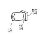
도 3a 는 본 발명의 시스템의 실시예에 따른 이미지 유닛(300)의 사시도이다. 이미지 유닛(300)은 하나 이상의 FPA(310) 및, FPA(310)가 있는 곳에 근접한 반도체 기판의 동일한 표면상에 형성된 집적 실리콘 온 칩(ISOC)(320)을 포함할 수 있다. 불행하게도, ISOC(320)를 이미저(imager)/FPA(310)의 다음에(즉, 기판의 동일한 표면에) ISOC(320)를 배치함으로써, 이미지 유닛(300)의 도달 범위(footprint)는 증가된다 (예를 들어, 길이 l1=4mm 로부터 l2 =6.5 mm 또는 그 이상으로 된다). 이것은 대응하는 내시경의 직경을 증가시키는데, 개구(예를 들어, 도 1a 의 184)를 통하여 내시경을 삽입하기 위하여 신체(예를 들어, 도 1a 의 182) 안에 더 큰 절개부 또는 개구(예를 들어, 도 1a 의 184 참조)가 필요하므로 이는 소망스럽지 않을 수 있다. 콤팩트한 이미지 유닛은 도 3b 에 도시되어 있다. 특히, 도 3b 는 본 발명의 시스템의 다른 실시예에 따른 콤팩트한 이미지 유닛(325)의 사시도이다. 이미지 유닛(325)은 기판의 제1 측에 FPA(330)을 구비하고 기판의 반대측에 ISOC(340)을 구비한다. 따라서, 이미저(325)는 ISOC(340)가 FPA(330)의 기판의 반대측상에 있는, 단일 FPA(330)의 도달 범위와 실질적으로 동일한 도달 범위를 가질 수 있다. 이미지 유닛(325)은 폴딩 이미저(folded imager, 325)로 지칭될 수 있다.3A is a perspective view of an
도 3c 는 ROI(115)로부터 이미지들을 캡쳐하기 위한 본 발명의 시스템의 실시예에 따른 폴딩 이미저(325C)를 가진 이미지 장치를 구비한 내시경(300C)의 개략적인 도면이다. 폴딩 이미저(325C)는 내시경(300C)의 길이 방향 축(365)을 따라서 축방향으로 적층되어 있는 적층체(360,360',360")로부터 형성될 수 있다. 이미지 장치(325C)는, 단일 FPA(330)의 위에서 이미지 장치(325C)(이것은 도 3b 에 도시된 이미지 장치(325)와 유사할 수 있다)의 후방 단부(374)에 있는 적어도 하나의 적층된 층에 형성된 프로세싱 회로(예를 들어, ISOC 를 포함)(340C) 및, 전방 단부(372)에 있는 단일의 FPA(330)를 포함할 수 있다. ISOC 적층체(340C)는 연결 범프(370)를 통하여 단일의 FPA(330)에 연결될 수 있다.3C is a schematic diagram of an
도 3d 는 ROI(115)로부터의 이미지를 캡쳐하기 위한 본 발명의 실시예에 따른 대안의 이미지 장치(325D)를 구비하는 내시경(300D)의 개략적인 도면이다. (도 3c)의 이미지 장치(325C)의 범프(370)에 의해 연결되는 적층체 대신에, 이미지 장치(325D)는 전방 단부(672)에 있는 단일 FPA(330)를 가지는 접힘 기판(380) 및, 이미지 장치(325D)의 후방 단부(374)에 있는 ISOC(340D)를 구비할 수 있다. 접혀진 유연성 기판(380)은 패턴이 형성된 실리콘 멤브레인, 또는 유연성 인쇄 회로 기판, 또는 다른 적절한 재료로 형성될 수 있다.3D is a schematic diagram of an
FPA(330)에 의해 캡쳐된 광학 이미지들(즉, 대물 렌즈 시스템으로부터 직접 수신된 이미지)은 (A/D 에 의하여) 디지탈 신호(예를 들어, 디지털 이미지 정보)로 변환되며, 디지털 신호는 FPA(330)의 뒤에 위치된 ISOC(340)와 같은 이미지 프로세서에 의해 처리될 수 있다. ISOC(340)는 디지털 신호(즉, FPA(330)에 의해 캡쳐된 광학 이미지를 나타내는 디지털 이미지 정보)를 처리하고, 사용자(예를 들어, 외과의사 등)가 ROI(115)(도 1a)의 3D/입체 이미지를 보도록 시스템의 디스플레이 스크린으로 송신되는 (예를 들어, 유선 또는 무선 통신 방법을 사용한다) 비디오 신호를 출력한다. 또한 시스템은 이후의 사용자를 위하여 이미지에 대응하는 3D 이미지 정보를 기록할 수도 있고, 그리고/또는 3D 이미지 정보를 원격 관찰을 위하여 (예를 들어, 멀리 있는 외과 의사등이 보도록) 하나 또는 그 이상의 위치로 전송할 수 있다.Optical images captured by the FPA 330 (ie, images received directly from the objective lens system) are converted (by A / D) into digital signals (eg, digital image information), and the digital signals are FPA It may be processed by an image processor such as
본 발명의 다른 실시예는 우측 및 좌측 동공(pupil)을 가진 분리 동공을 사용한다. 입체 비젼 또는 3 차원 비젼(3D)을 달성하려면, 상이한 우측 및 좌측 이미지들이 FPA 에 의해 캡쳐되어 3D 이미지를 형성하도록 처리될 수 있다. 이전의 일부 실시예에서, (예를 들어, 우측 및 좌측 이미지 채널들에 각각 대응하는) FPA 의 우측 및 좌측 부분 양쪽(또는 우측 및 좌측 동공들)이 광/이미지를 동시에 받는다. 그러나, 각각의 이미지 채널이 도 1a 에 도시된 바와 같이 자체의 구멍(bore)(예를 들어, 110, 120)을 가지는 실시예들에서, 우측 및 좌측 동공 또는 렌즈(112,122)에 의해 각각 입력된 우측 및 좌측 이미지들은 도 1b 에 도시된 바와 같이 FPA(130)의 상이한 영역(132,143)에 이미지를 만들며, 따라서 3D 이미지를 형성하도록 처리될 수 있는 입체적인 이미지 정보를 제공한다.Another embodiment of the present invention uses separate pupils having right and left pupils. To achieve stereoscopic or three-dimensional vision (3D), different right and left images can be processed to be captured by FPA to form a 3D image. In some previous embodiments, both the right and left portions (or right and left pupils) of the FPA (eg, corresponding to the right and left image channels respectively) receive light / image simultaneously. However, in embodiments in which each image channel has its own bore (eg, 110, 120) as shown in FIG. 1A, input by the right and left pupils or
다른 실시예들에서, 우측 및 좌측 동공/렌즈들 양쪽이 이미지를 동시에 받게 하는 대신에, 내시경에 의해 캡쳐된 이미지가 한번에 하나씩만 단일의 동공을 통과할 수 있도록 다양한 계획들이 제안될 수 있다.In other embodiments, instead of allowing both the right and left pupils / lenses to receive the image simultaneously, various schemes may be proposed such that only one image captured by the endoscope can pass through a single pupil at a time.
예를 들어, 복합 다중 대역 통과 필터(Conjugated Multi-Bandpass Filters;CMBSs)가 제공됨으로써 우측 및 좌측 동공들을 덮거나 또는 그것에 통합될 수 있는데, 그 동공들은 우측 및 좌측 동공 부분들을 가지는 단일의 렌즈들에 의해 형성될 수 있거나, 또는 단일 및/또는 이중 구멍(bore) 내시경에서 사용되도록, 한쪽 렌즈들은 우측 동공용이고 한쪽 렌즈들은 좌측 동공용인, 2 개의 전용 렌즈들에 의해 형성될 수 있다. 우측 및 좌측 동공들 위에 위치되거나 그것과 통합된 CMBF 대신에, 스위치 가능 액정(LC) 셔터 또는 기계적 셔터들이 콘트롤러에 의해 제어됨으로써, 오직 하나의 동공만이 ROI 로부터 반사된 이미지 광을 한번 통과시켜서, 그 통과된 광을 FPA 의 실질적으로 전체 영역에 걸쳐 투사하며, 따라서 FPA 의 오직 일부에만 이미지를 투사하는 것에 비교하여 해상도가 증가되는데, 여기에서 프로세서는 6 개의 순차적인 서브 이미지들(RR, RL, GR, GL, BR, 및 BL)로부터 3D 이미지를 구성하고 그 각각의 서브 이미지는 전체 FPA 영역에 투사된다. 물론, 소망된다면, 우측 및 좌측 이미지들이 동시에 FPA 의 우측 및 좌측 부분들에 걸쳐 동시에 투사될 수 있어서 해상도의 감소를 가져올 수 있지만, 3D 이미지를 형성하는데 있어서 신속한 획득 시간이 달성되는데, 왜냐하면 이러한 경우에 3D 이미지들은 동시적인 우측 및 좌측 서브 이미지(RR RL, GR GL및 BR, BL)의 3 번(6번이 아닌)의 순차적인 투사의 프로세서에 의해 구성되기 때문이다. 예를 들어, 콘트롤러 및/또는 프로세서는 우측 및 좌측 동공들 위에 위치된 우측 및 좌측 LC 셔터들에 인가되는 전압을 변화시킬 수 있어서, 하나의 LC 셔터가 개방/투명하게 됨으로써 이미지 광을 통과시키고, 다른 LC 셔터는 폐쇄되거나 또는 투명하지 않게 되어 다른 셔터를 통해 광이 통과하는 것을 차단한다. 대안으로서, 도 4a 및 도 4b 에 도시된 바와 같이 콘트롤러는 기계적인 셔터의 움직임을 제어할 수 있다.For example, Conjugated Multi-Bandpass Filters (CMBSs) may be provided to cover or integrate the right and left pupils, which may be integrated into a single lens having right and left pupil portions. Can be formed by two dedicated lenses, one lens for the right pupil and one lens for the left pupil, for use in single and / or double bore endoscopes. Instead of the CMBF located above or integrated with the right and left pupils, switchable liquid crystal (LC) shutters or mechanical shutters are controlled by the controller so that only one pupil passes the image light reflected from the ROI once, The passed light is projected over substantially the entire area of the FPA, so the resolution is increased compared to projecting an image only on a portion of the FPA, where the processor has six sequential sub-images (RR , RL , GR , GL , BR , and BL ) constitute a 3D image and each sub-image thereof is projected over the entire FPA area. Of course, if desired, the right and left images can be projected simultaneously across the right and left portions of the FPA, resulting in a reduction in resolution, but a fast acquisition time is achieved in forming the 3D image, because in this case 3D images can be viewed simultaneously with the right and left sub-images (RR RL , GR GL And BR , BL ) by the processor of the third (not six) sequential projection. For example, the controller and / or processor may change the voltage applied to the right and left LC shutters located above the right and left pupils, allowing one LC shutter to open / transparent to allow image light to pass through, The other LC shutters become closed or not transparent to block light from passing through the other shutters. Alternatively, as shown in FIGS. 4A and 4B, the controller can control the movement of the mechanical shutter.
특히, 도 4a 는 본 발명의 시스템의 다른 실시예에 따른 내시경 시스템(400)의 개략적인 도면이다. 내시경 시스템(400)은 하나 또는 그 이상의 콘트롤러(410), 서브 이미지들의 시간 멀티플렉싱(time multiplexing)을 허용하는 마이크로 전자-기계(micro-electro-mechanical; MEMS) 셔터(415), 조명 부분(420,420'), 렌즈 부분(425) 및, FPA(430)를 포함한다. 조명 부분(750)은 FPA 가 칼러 필터를 가지는 칼러 FPA 인 경우에 예를 들어 외부 백색 광원과 같은 광원을 구비할 수 있거나, 또는 예를 들어 레드(R), 그린(G) 및 블루(B) 광과 같은 상이한 칼러의 광을 순차적으로 제공하는 광원(들)을 구비할 수 있다. 광학적 안내부(optical guide)들도 제공되어 외부 광을 내시경의 기단 단부로부터 말단 단부로 지향시키며, 다음에 광은 내시경으로부터 이탈되게 지향되어 ROI(115)를 조명한다. 물론 칼러 광원(들)도 단색 FPA 에서 사용될 수 있으며, 여기에서 각각의 칼러는 순차적으로 ROI(115)를 조명한다. 이후에 설명되는 바로서, 렌즈 부분(425)은 셔터(415)의 설정에 따라서 ROI(115)의 우측 또는 좌측 이미지를 FPA(430)상에 투사할 수 있는 하나 또는 그 이상의 렌즈들을 구비할 수 있다. 셔터(415)는 우측 셔터 개구(또는 동공)(440) 및 좌측 셔터 개구(또는 동공)(445)를 구비할 수 있어서, 이들은 콘트롤러(410)로부터의 제어 신호에 기초하여 광이 그것을 통과하는 것을 허용하거나 차단할 수 있다. 따라서, 우측 및 좌측 개구(동공)(440,445)들은 각각 필터, 셔터 또는 게이트들을 구비할 수 있으며, 이들은 콘트롤러(410)의 제어하에 작동되며, 한번에 우측 또는 좌측 이미지들만이 FPA(430)상에 투사되는 것을 허용하기 위하여, 콘트롤러(410)로부터 셔터(415)로 송신된 하나 또는 그 이상의 제어 신호에 기초하여 그것을 통해 광을 통과시키거나 또는 광의 통과를 차단하도록 작동한다.In particular, FIG. 4A is a schematic diagram of an
따라서, 오직 우측 이미지만이 FPA(30)에 투사되는 것을 보장하도록, 광이 우측 셔터 개구를 통과하는 것을 허용하기 위하여 우측 셔터 개구(440)가 개방될 수 있으며, 광이 좌측 셔터 개구를 통과하는 것을 차단하기 위하여 좌측 셔터 개구(445)는 실질적으로 또는 완전히 폐쇄된다. 그러므로, FPA(430)는 (예를 들어, 주어진 파장의) 우측 이미지를 캡쳐하도록 제어될 수 있다. 따라서, 오직 좌측 이미지가 FPA(430)에 투사되는 것을 보장하도록, 광이 좌측 셔터 개구를 통해 통과되는 것을 허용하기 위하여 좌측 셔터 개구(445)는 개방될 수 있고, 광이 우측 셔터 개구를 통과하는 것을 차단하기 위하여 우측 셔터 개구(440)는 실질적으로 또는 완전히 폐쇄될 수 있다. 따라서, FPA(430)는 좌측 이미지 또는 그것의 일부(예를 들어, 레드, 그린, 또는 블루 부분/서브 이미지)를 캡쳐하도록 제어될 수 있다. 그러므로, 예를 들어, 우측 동공은 차단될 수 있고 광은 좌측 동공을 통해서만 통과되는 것이 허용될 수 있으며, 그 역의 관계도 성립된다. 셔터는 액정(LC) 유형의 셔터를 포함할 수 있고, 액정 유형의 셔터는 (예를 들어 콘트롤러(410)에 의해) 전자적으로 제어될 수 있어서 광이 대응하는 우측 또는 좌측 동공(440,445)을 통과하는 것을 각각 허용하거나 또는 차단한다. 콘트롤러(410)는 우측 및 좌측 동공(440,445)을 덮는 우측 또는 좌측 셔터에 각각 전압을 인가할 수 있어서 대응하는 셔터의 상태(예를 들어, 개방 또는 차단)를 제어한다. 그러나, 설명된 바와 같이, 셔터(415)가 기계적 셔터 부분(예를 들어, 제어 부분(410)에 의해 제어되는 모터에 결합된 선형 셔터 또는 회전 디스크)을 구비할 수 있으며, 그것은 동공들중 하나를 차단하도록 2 개의 동공(440,445) 사이에서 전후로 선형적으로 움직이거나 또는 기계적으로 회전될 수 있다.Thus, the
도 4B 는 본 발명의 시스템의 실시예에 따른 내시경 시스템(400)의 정면도이다. 셔터(415)는 내시경(400)의 말단 단부에 장착될 수 있다. 셔터(415)는 좌측 동공(445)을 덮거나 폐쇄시키는 위치에서 도시됨으로써 광은 좌측 동공(445)을 통과할 수 없다. 역으로, 우측 동공(440)은 개방 위치에서 도시됨으로써, 광은 우측 동공(440)을 통과할 수 있다. 따라서 예를 들어 ROI(115)의 이미지들은 현재의 사이클에서 우측 동공(440)만을 통과할 수 있고 좌측 동공(445)을 통과하지 않는다.4B is a front view of an
본 발명의 시스템의 다양한 실시예들에서, 단색 FPA 의 사용 및 칼러 광에 의한 조명 대신에, 칼러 필터를 가지는 FPA 또는 칼러 FPA 와 함께 백색광이 사용될 수 있다. 예를 들어, 다른 설명된 실시예들에서와 같이 도 4a 및 도 4b 에 도시된 실시예에서, 조명 부분(420,420')은 백색광을 제공할 수 있고 FPA(430)는 칼러 이미지를 형성할 수 있는 칼러 FPA 를 포함할 수 있다. 칼러 FPA 는 예를 들어 RGB 필터들의 칼러 필터 어레이가 우측 및 좌측 셔터 개구(440,445)들에 각각 위치되어 있는 단색 FPA 를 포함할 수 있다. 컬러 필터들은 RGB 필터 그룹을 포함할 수 있고, 예를 들어 휘일(예를 들어, 다른 곳에서 설명된 회전 휘일)상에 제공될 수 있거나, 또는 콘트롤러(410)에 의해 제어될 수 있거나, 또는 다른 콘트롤러/프로세서에 의해 제어될 수 있어서, 특정의 칼러를 차단하고 그리고/또는 다른 칼러가 그것을 통과하는 것을 허용한다. 따라서, 칼러 이미지들은 단색 FPA 를 사용하여 형성될 수 있는데, 단색 FPA 는, 복합 다중 대역 통과 필터(Conjugated Multi-Bandpass Filters;CMBSs)와 같이 동공/렌즈(440,445)에 있는 칼러 필터(예를 들어, RGB)를 가지고, 그리고/또는 콘트롤러 또는 프로세서(410)에 의해 소망되는 대역들중 각각의 하나에 선택적으로 튜닝될 수 있고 프로세서에 의해 동기화되는 튜닝 가능 필터들을 가지며, (레드(R), 그린(G) 및 블루(B) 칼러들 각각에 대하여, 또는 임의의 소망되는 칼러들에 대하여, 우측 및 좌측 이미지들이 동시에 FPA 의 우측 및 좌측 영역상에 이미지를 만드는 경우) 3 개의 서브 이미지를 캡쳐하거나, 또는 (6 개의 RGB 우측 및 좌측 서브 이미지들 각각이 FPA 의 실질적으로 전체 영역에 이미지를 만드는 경우) 6 개의 서브 이미지들을 캡쳐하는, 3 또는 6 개의 조명 시퀀스들을 가지는 것과 같은 조명으로 이루어진다.In various embodiments of the system of the present invention, instead of the use of monochromatic FPA and illumination by color light, white light may be used with FPA or color FPA with color filters. For example, in the embodiment shown in FIGS. 4A and 4B as in other described embodiments, the
이러한 경우에, ROI(115)는 (예를 들어, 백색광 대신에) 칼러 광으로 조명되어, 우측 및 좌측 동공/렌즈(440,445)들과 통합되거나 그 위에 형성된 튜닝 가능 필터들 또는 CMBF 를 통하여 RGB 이미지들을 FPA 로 순차적으로 제공할 수 있다.In this case,
셔터들은 특정의 시간에 특정의 칼러를 통과시키고 다른 칼러를 차단하기 위하여 콘트롤러(410)의 제어하에 RGB 광과 함께 이용할 수 있다. 따라서, 예를 들어 소망의 칼러 광 및/또는 서브-레드(sub-red) 광을 통과시키도록 칼러(예를 들어, R, G, 또는 B) 필터가 활성화되거나 또는 튜닝 가능 필터가 튜닝되었을 때 (예를 들어 조명원에 의해) 레드 광이 제공되도록, 콘트롤러(410)는 셔터들(기계적 셔터들이거나 또는 LC 셔터들)을 조명과 동기화시키는 기능을 포함할 수 있다.Shutters may be used with RGB light under the control of
이미지들이 한번에 하나씩, 즉, 순차적으로 하나의 동공/렌즈들을 통과하는 것을 보장하도록, 그리고 한번에 하나의 동공을 통한 이미지들의 차단/통과와 순차적인 칼러 조명을 동기화시킬 필요성을 제거하도록, 셔터 또는 스위치를 사용하는 대신에, 정합 상보적이거나(matched complementary) 또는 복합 다중 대역 통과 필터(Conjugated Multi-Bandpass Filters;CMBSs), 및/또는 튜닝 가능 필터(들)가 이용될 수 있다는 점을 생각할 수 있다. 특히, 상보적인 우측(RRGRBR) 및 좌측(RLGLBL) 다중 대역 통과 필터들이 우측 및 좌측 동공들에서 각각 사용된다. 또한, 우측 및 좌측 동공/렌즈들에 위치된 상보적인 우측(RRGRBR) 및 좌측(RLGLBL) 다중 대역 통과 필터들에 정합되는 다중 대역 통과 필터를 통해 조명이 제공된다.To ensure that images pass through one pupil / lens one at a time, ie sequentially, and to eliminate the need to synchronize sequential color illumination with blocking / passing of images through one pupil at a time, a shutter or switch Instead of using, it is conceivable that matched complementary or Conjugated Multi-Bandpass Filters (CMBSs), and / or tunable filter (s) may be used. In particular, complementary right (RR GR BR ) and left (RL GL BL ) multiband pass filters are used in the right and left pupils, respectively. In addition, illumination is provided through a multi-band pass filter that matches the complementary right (RR GR BR ) and left (RL GL BL ) multi-band pass filters located in the right and left pupils / lenses. do.
우측 및 좌측 동공들에 있는 우측(RRGRBR) 및 좌측(RLGLBL)의 복합적이거나 또는 상보적인 다중 대역 통과 필터들은 에너지를 필요로 하지 않고, 움직이는 부분들을 가지지 않으며, 동기화를 필요로 하지 않는데, 왜냐하면 이들 우측(RRGRBR) 및 좌측(RLGLBL) 다중 대역 통과 필터들은 조명 광에 정합되기 때문이다. 따라서, ROI 가 우측 레드 광(RR)으로 조명될 때, RR 광은 관심 대상으로부터 반사되어 우측 동공만을 통해 우측 동공에 있는 대역 필터(RR)을 통과하거나 그 안으로 진입하며, 좌측 동공 위에 위치된 좌측(RLGLBL) 다중 대역 통과 필터에 의하여 좌측 동공을 통과하거나 또는 그 안으로 진입하는 것은 차단된다.The complex or complementary multiband pass filters on the right (RR GR BR ) and the left (RL GL BL ) in the right and left pupils do not require energy, have no moving parts, No synchronization is required because these right (RR GR BR ) and left (RL GL BL ) multiband pass filters are matched to the illumination light. Thus, when the ROI is illuminated with the right red light (RR ), the RR light is reflected from the object of interest and passes through or enters the band filter (RR ) in the right pupil only through the right pupil and over the left pupil. Passing into or entering the left pupil by a positioned left (RL GL BL ) multi-band pass filter is blocked.
도 5 는 본 발명의 시스템의 실시예에 따른 내시경 시스템(500)의 개략적인 도면이다. 내시경 시스템(500)은 (도 1a 에 도시된 2 중 대물 렌즈 내시경(100)의 2 개 구멍(110,120)들을 가지는 대신에) 단일의 구멍 또는 하우징(505)을 구비하는 내시경(502)을 포함할 수 있다. 내시경 시스템(500)은 신체(182) 내부의 목적물 또는 ROI(115)의 입체적인 3-D 이미지를 제공할 수 있다. 사용되는 동안, 내시경(502)은 개구 또는 공동(184)을 통해 신체(182) 안으로 삽입될 수 있으며, 개구 또는 공동은 예를 들어 자연적인 개구, 절개부(incision) 등을 포함할 수 있다. 하우징(505)은 말단 단부(510) 및 기단 단부(515)를 가지며, 말단 단부(510)는 신체(182)의 공동 또는 개구(184) 안으로 삽입될 수 있다. ROI(115)의 광학적 이미지들을 얻기 위한 이미지 장치(325)는 말단 단부(510)에 위치되고, 투사된 이미지를 캡쳐할 수 있는 이미저(imager) 또는 FPA(300) 및, FPA(330)로 캡쳐된 이미지들을 처리하고 비디오 신호와 같은 출력 신호를 형성하는 프로세서를 구비할 수 있다. 프로세서는 ISOC 회로(340) 또는 다른 적절한 프로세서(들)를 포함할 수 있으며, 여기에서 프로세서(340)를 포함하는 ISOC 는 FPA(330)의 뒤에 있고 FPA(330)와 같은 도달 범위(footprint)를 가지고, 도달 범위(footprint)의 길이 또는 직경은 1 내지 4 mm 와 같이 4 mm 또는 그 미만으로서, 3-4 mm, 2-4 mm, 2-3 mm 등과 같은 그 사이의 어떠한 크기라도 포함한다.5 is a schematic diagram of an
이미지 장치(325)는 유선 및/또는 무선 결합 기술 및/또는 연결 장치들을 이용하여, 하나 또는 그 이상의 조명원(550), 디스플레이(555), 콘트롤러(595)에 결합될 수 있다. 예를 들어, 케이블(545)은 이미지 장치(325)를 조명원(550), 디스플레이(555) 및/또는 콘트롤러(595)에 결합할 수 있다. 케이블(545)은 ROI(115)의 광학적 디스플레이를 다차원(예를 들어 3D 등)으로 디스플레이하기 위하여, (예를 들어 ISOC 로부터의) 비디오 신호를 디스플레이(555)로 송신하는 신호 라인을 포함할 수 있다. 무선 결합은 ISOC(340)로부터 디스플레이(555)로 비디오 신호들을 송신하도록 이용될 수 있다는 점이 더 생각된다. 케이블(545)은 이미지 장치(325)의 전방 단부에서 조명원(550)으로부터 조명기(150)로 광의 채널을 만들도록 하나 또는 그 이상의 광 안내부를 구비할 수 있다. 그러나, 콘트롤러(595)의 제어하에 ROI(115)를 조명하기 위하여 조명기들이 이미지 장치(325) 안에 포함될 수 있다는 점이 생각된다.
이미지 장치(325)는 ROI(115)의 이미지들을 캡쳐하도록 관심 영역(ROI)(115)을 향하는 (이미지 장치(625)의) 전방 단부(565)에 FPA(330)와 같은 단일 초점 평면 검출기 어레이(single focal plane detector array)를 포함할 수 있다. 이미지 장치(325)는 예를 들어 ISOC(340)와 같은 적절한 프로세서를 가진 처리 회로를 더 구비할 수 있는데, 그것은 FPA(330)의 뒤에서 (이미지 장치(325)의) 후방 단부(575)에 위치될 수 있고 FPA(330)와 같은 도달 범위(footprint)를 가짐으로써 ISOC(340)는 이미지 장치(325)의 외측 단면(580)을 확장시키지 않으며, 여기에서 단면(580)은 1-4 mm 와 같이 4mm 보다 작을 수 있다. ISOC(340)는 디스플레이(555)상에 디스플레이하기 위하여 FPA(330)에 의해 캡쳐된 광학 이미지들을 비디오 신호로 변환시키도록 작동될 수 있다.The
본 발명의 시스템의 실시예에 따른 내시경(502)의 정면도는 도 6 에 도시되어 있다. 이미지 장치(325)는 우측 및 좌측 동공(585,590)들을 각각 구비할 수 있고, 이들은 상보적인 우측(RR, GR, BR) 및 좌측(RL, GL, BL) 다중 대역 통과 필터들을 각각 가지고, 여기에서 (도 1a 의 2 개 구멍(110,120)들에 있는 2 중 렌즈(112,122)와는 다르게,) 단일의 구멍(bore) 또는 하우징(505)에 있는 단일의 렌즈(730)(도 7a)들은 우측 및 좌측 이미지들을 FPA(330)에 투사한다. 따라서, 우측 및 좌측 동공(585,590)들은, FPA 상에 우측 및 좌측 이미지들을 독립적으로 그리고 동시에 이미지 형성하게 되는 도 1a 의 2 중 대물 렌즈 내시경의 우측 및 좌측 렌즈(112,122)와는 각각 상이하다. 내시경(502)의 단면적(580)은 신체의 절개부 또는 개구를 용이하게 통과하도록 콤팩트하다.A front view of an
작동중에, 우측 동공(585)은 도 7 및 도 9 에 도시된 바와 같은 우측의 3 개 통과 대역(RRGRBR, 710)을 가진 (도 9 에 도시된 복합 다중 대역 통과 필터(CMBF) (710, 720)과 같은) 우측 다중 대역 통과 필터를 통하여 우측 이미지를 받는다. 유사한 방식으로, 좌측 동공(590)은 도 9 에 도시된 좌측의 3 개 통과 대역(RLGLBL)을 가지는 (도 7 및 도 9 에 도시된 필터(720)와 같은) 좌측 다중 대역 통과 필터를 통해 좌측 이미지를 수광하며, 도 9 는 본 발명의 시스템의 실시예에 따른 복합 다중 대역 통과 필터(CMBF)(710,720)의 통과 대역 및 정지 대역(910,920)을 나타내는 그래프이다. 도 9 에 도시된 바와 같이, 우측의 3 개 통과 대역(RRGRBR)을 가진 우측 다중 대역 통과 필터(710)는 좌측의 3 개 통과 대역(RLGLBL)을 가지는 좌측 다중 대역 통과 필터(720)의 상보체(complement)이다. 즉, 우측 다중 대역 통과 필터(710)의 통과 대역(RRGRBR)은 좌측 다중 대역 통과 필터(720)의 정지 대역(920)에 대응한다. 마찬가지로, 좌측 다중 대역 통과 필터(720)의 통과 대역(RLGLBL)은 우측 다중 대역 통과 필터(710)의 정지 대역(910)에 대응한다.In operation, the
도 7a 는 본 발명의 시스템의 실시예에 따른 내시경 시스템(500)(도 5)의 이미지 장치(325) 구성 요소들의 개략적인 도면이다. 이미지 장치(325)는 렌즈 시스템(730)을 더 포함할 수 있다. 렌즈 시스템(730)은, 우측 이미지(740) 및 좌측 이미지(750)를 직접적으로 (단일의) FPA(330)상에서 이미지를 만들기 위한 초점 렌즈 및 대물 렌즈와 같은 몇개의 렌즈들을 포함할 수 있다. 조명기(150)(도 4D 및 도 6 참조)들은 (도 8 에 도시된) 복합 다중 대역 통과 필터(CMBF)(810)를 통해 ROI(115)를 조명하는데, 이것은 우측의 3 개 통과 대역(RRGRBR) 및 좌측의 3 개 통과 대역(RLGLBL)을 가진다. 다중 대역 통과 필터(810)는 우측 및 좌측 동공들을 덮는 (도 7a-7b 및 도 9 에 도시된) 우측 다중 대역 통과 필터(710) 및 좌측 다중 대역 통과 필터(720)에 각각 정합될 수 있어서, ROI(115)가 우측 레드 대역(RR)과 같은 하나의 칼러 광으로 조명될 때, ROI(115)로부터의 RR 광은 우측 동공(585)을 덮는 우측 다중 대역 통과 필터(710, RRGRBR)의 통과 대역(RR)을 통해 우측 동공(585)을 통과하고, 좌측 동공(590)을 덮는 좌측 다중 대역 통과 필터(720, RLGLBL)의 정지 대역(920)(도 9)에 의해 좌측 동공(590)을 통과하는 것이 방지된다. (도 11a 와 관련하여 설명되는 바와 같이) 6 개의 서브 이미지들이 전체 FPA 에 이미지를 만드는, 대역(RRGRBRRLGLBL)에서의 광들의 임의 시퀀스에 의한 6 번의 순차적인 조명 이후에, 완전한 칼러 이미지가 이루어진다. 이전에 설명되고 도 11b 와 관련하여 설명될 바로서, 양쪽의 우측 및 좌측 이미지들, 예를 들어, RR 및 RL 이미지들은, 양쪽의 우측 칼러 및 좌측 칼러를 가지고 ROI 를 동시에 조명함으로써 (예를 들어, RR 및 RL 동시 조명으로써) FPA 상에 동시에 이미지가 만들어질 수 있고, 다음에 3 개의 순차적인 조명 이후에 완전한 칼러 이미지가 얻어진다. 비록 조명원(550)(도 5 참조)이 내시경(502)으로부터 멀리 위치할 수 있을지라도, 조명원(550)이 내시경(502)의 하우징(505) 안에 위치될 수 있고 조명기(150)에 근접할 수 있거나 또는 조명기에 일체로 형성될 수 있다.FIG. 7A is a schematic diagram of components of the
도 7b 에 도시된 바와 같이, 우측 및 좌측 서브 이미지(RRGRBRRLGLBL)를 통과시키도록 이용된 우측 및 좌측 복합 다중 대역 통과 필터(CMBF, 710',720')들은 각각 반원형의 형상을 가질 수 있으며, 이들은 서로 다음에 배치됨으로써 완전한 원형의 복합 다중 대역 통과 필터를 형성하며, 복합 다중 대역 통과 필터는 렌즈의 전방 및/또는 후방 표면상에 그리고/또는 투명한 지지 기판상에 제거 가능하게 배치되는 것과 같이, 렌즈 및/또는 투명 지지 기판 위에 배치될 수 있거나, 또는 대물 렌즈로 제거 가능하게 삽입되거나, 또는 렌즈와 일체화됨으로써, 이미지 장치(325)의 우측 및 좌측 동공들을 덮고 그리고/또는 형성한다. 이것은 단순하게 CMBF 쌍(710',720')을 제거함으로써 쌍안의(binocular) 2 개 동공 이미지 유닛 또는 카메라(325)를 단안의(monocular) 카메라로 용이하게 전환하게 하여, 내시경의 사용자/작업자가 환경 및 소망하는 시야 거리에 따라서 더 나은 이미지들을 얻도록 쌍안 이미지형성(imaging) 및 단안 이미지형성 사이에서 선택하는 것을 허용한다. 예를 들어, 단안 이미지형성은 긴 시야 거리로 관찰하도록 선택되어 이용될 수 있는데, 그러한 경우는 깊이 인식(depth perception)이 중요하지 않으며, 이에 반해 깊이 인식을 얻기 위한 쌍안의 이미지형성은 짧은 거리에서 관찰하도록 이용될 수 있다.As shown in FIG. 7B, the right and left sub-images (RR GR BR The right and left complex multiband pass filters (CMBF, 710 ', 720') used to pass RL GL BL ) may each have a semi-circular shape, which are placed next to each other to form a complete circular complex Forming a multi-band pass filter, wherein the composite multi-band filter is disposed over the lens and / or transparent support substrate, such as removably disposed on the front and / or rear surface of the lens and / or on the transparent support substrate. Can be, or removably inserted into the objective lens, or integrated with the lens, covering and / or forming the right and left pupils of the
예시적으로, 6 내지 12 mm의 작동 거리에 대하여, CMBF 쌍 (710,720)(710',720')을 이용하는 이미지 시스템은, 6 내지 12 mm 사이의 시야 거리 범위에 걸쳐서 CMBF가 없는 것보다 더 나은 깊이 해상도를 제공한다. 향상된 깊이 인식 또는 깊이 해상도는, 도 7b 에 도시된 반원형의 CMBF 쌍(710',720')에 의해 우측 및 좌측 이미지들이 캡쳐되는 실시예들 뿐만 아니라, 0.5 mm 내지 2 mm 사이의 거리로 분리된 개구들/통공들 또는 우측 및 좌측 렌즈들을 이용하는 실시예들에 의하여 네가티브 렌즈 또는 광각 렌즈를 이용하는 60 도(degree)의 시야를 가진 5 mm 내지 2cm 의 작동 거리 또는 시야 거리에서 제공된다.Illustratively, for an operating distance of 6 to 12 mm, an imaging system using CMBF pairs 710, 720 (710 ', 720') is better than no CMBF over a range of viewing distances between 6 and 12 mm. Provide depth resolution. Improved depth recognition or depth resolution is separated by a distance between 0.5 mm and 2 mm, as well as embodiments in which right and left images are captured by semicircular CMBF pairs 710 ', 720' shown in FIG. 7B. Embodiments using apertures / through holes or right and left lenses are provided at a working distance or viewing distance of 5 mm to 2 cm with a 60 degree field of view using a negative or wide angle lens.
도 8 은 본 발명의 시스템의 실시예에 따른 내시경(500)의 조명원(550)(도 5 에 도시됨)의 개략적인 도면이다. 조명원(550)은 복수개의 소스(source) (830,832,834,840,842,844) 및 다중 대역 통과 필터(810)의 대응하는 통과 대역 필터(PBFs)(RR,GR,BR,RL,GL,및 BL)를 포함할 수 있다. 소스(830,832,834,840,842,및 844)들은 제논(Xenon) 소스등과 같은 임의의 적절한 백색광 소스들을 포함할 수 있다.8 is a schematic diagram of an illumination source 550 (shown in FIG. 5) of an
콘트롤러(595)(도 5 에 도시됨)는 조명원(550)을 제어할 수 있어서, 조명원(550)은 이미지 장치(325)의 조명기(150) 및 광 안내부(820)들을 통하여 ROI(110)를 조명하기 위하여 한번에 하나씩 광 소스(830,832,834,840,842,844)를 순차적으로 켠다. 소망된다면, 렌즈(825)들이 CMBF(810)와 광 안내부(820) 사이에 제공될 수 있다. 따라서, 소스(830,832,834,840,842,844)로부터의 광이 조명 다중 대역 통과 필터(810)의 대응하는 조명 통과 대역 필터(PBF)(RR,GR,BR,RL,GL,및 BL)를 통과할 수 있어서, 관심 영역(ROI)(115)은 각각의 조명 간격 동안에 3 개의 우측 통과 대역(RRGRBR) 및 3 개의 좌측 통과 대역(RLGLBL)내에서 광에 의해 한번에 하나씩 조명된다. 각각의 조명 간격 동안에, 조명광은, ROI(115)로부터 반사되고 우측 및 좌측 동공(585,590)을 덮는 우측 또는 좌측 다중 대역 통과 필터(710,720)(도 7a-도 7b)를 통과하여, 단일의 FPA(330)의 실질적으로 전체 또는 전부의 영역(1110)(도 11a)에 투사되고 IOSC(340)와 같은 이미지 프로세서에 의해 처리된, ROI(115)의 이미지를 형성한다. 다음에, 6 번의 조명 간격 이후에, 즉, RRGRBR및 RLGLBL의 대역에서의 광에 의한 조명 이후에, FPA(330)에 의해 캡쳐된 개별의 이미지들은 중첩되어 완전한 칼러 이미지를 형성한다. 예를 들어, ISOC(340)로부터의 이미지 데이타는 3 또는 6 개의 서브 이미지들 및/또는 이미지 데이타로부터 3D 이미지들을 조합하고 형성하도록 디스플레이 사이트(display site)에서의 알고리듬을 이용하여 처리된다. 우측 및 좌측 이미지들은 디스플레이(555)의 관찰 평면에서 중첩될 수 있다. 따라서, 6 번의 조명 간격 이후에, 3 개(RGB)의 우측 이미지들이 전체 FPA 영역(1110)(도 11a)상에서 서로의 위에 중첩되고 3 개(RGB)의 좌측 이미지들은 전체 FPA 영역(1110)상에서도 서로의 위에 중첩된다. 6 개의 이미지 정보 또는 데이타가 디스플레이(555)(도 5)상에서 디스플레이되는 3D 이미지들을 형성하도록 프로세서에 의해 처리되고 상호 관련(correlation)된다. 요약하면, 실질적으로 전체 FPA 영역(1110)(도 11a)상에 형성된 완전 칼러를 형성하도록 6 개의 이미지들이 이용될 수 있다. 즉, (임의의 시퀀스에서) 6 개의 이미지들(RR,GR,BR,RL,GL,BL)중 각각의 하나가 FPA(330)의 전체 영역(1110)(도 11a)상에 형성될 수 있다.The controller 595 (shown in FIG. 5) may control the
6 개의 제논(Xenon)(백색) 광원들을 이용하는 조명의 임의 시퀀스들이 이용될 수 있는데, 여기에서 3 개(RRGRBR)의 우측 서브 이미지(sub-image)들이 수집되어 중첩됨으로써 우측 이미지를 형성할 수 있고, 3 개(RLGLBL)의 좌측 서브 이미지(sub-image)들이 수집되어 중첩됨으로써 좌측 이미지를 형성할 수 있다. 즉, 6 개의 소스(830,832,834,840,842,844)들을 제공하는 조명은 RR,GR,BR,RL,GL,BL 또는 RR,RL,GR,GL,BR,BL등과 같은 임의의 시퀀스들일 수 있다. 각각의 칼러는 RedRight(RR) 및 RedLeft(RL)과 같이 우측 및 좌측 대역으로 분할되기 때문에, 우측 및 좌측 이미지들이 정확하게 같은 칼러는 아니며, 동위색(metamer)이라는 점이 주목되어야 한다.Any sequences of illumination using six Xenon (white) light sources can be used, where three (RR GR BR ) right sub-images are collected and superimposed so that the right image 3, the left sub-images (RL GL BL ) may be collected and overlapped to form a left image. That is, an illumination providing six sources 830,832,834,840,842,844 may be RR , GR , BR , RL , GL , BL or RR , RL, GR , GL , BR , BL , etc. It can be any sequences. Since each color is divided into right and left bands, such as RedRight (RR ) and RedLeft (RL ), it should be noted that the right and left images are not exactly the same color, but are metamers.
또한, 6 개의 조명 이후에 완전 칼러 이미지를 수집하는 대신에 (여기에서 6 개 이미지들 각각은 전체 FPA(330)상에 형성된다), 3 개의 다중 대역 통과 필터를 가지는, 오직 3 개의 제논(백색) 광원을 이용하는 3 번의 조명 이후에 완전 칼러 이미지가 수집될 수 있으며 (여기에서 각각의 우측 이미지 및 좌측 이미지는 도 11b 의 FPA(330')과 같은 이미지 캡쳐부의 개별적인 우측 및 좌측 절반(1150,1155)상에 동시에 투사된다), 즉, 제1 Xe 광원은 RR,RL의 대역을 가지는 필터를 통해 광을 제공하고, 제2 Xe 광원은 GR,GL의 대역을 가지는 필터를 통해 광을 제공하고, 제3 Xe 광원은 BR,BL의 대역을 가지는 필터를 통해 광을 제공한다. 따라서, 대역(RR,RL)에서의 광을 이용하는 제1 조명 이후에, 우측 및 좌측 레드 이미지들이 우측 및 좌측 FPA 영역에 동시에 이미지를 만들고 (예를 들어, 도 1b 의 132,134 및 도 11b 의 1155 및 1150 참조), 대역(GR,GL)에서의 광에 의한 제2 조명은 우측 및 좌측 FPA 영역(132,134) 상에 동시에 우측 및 좌측 그린 이미지들을 만드는데 이용되고 (여기에서 그린 이미지들은 레드 이미지들에 중첩된다), 대역(BR,BL)에서의 광에 의한 제3 조명은 우측 및 좌측 FPA 영역(132,134)상에 우측 및 좌측 블루 이미지들을 동시에 만들도록 이용된다 (여기에서 블루 이미지들은 이전의 레드 이미지 및 그린 이미지상에 중첩된다). 다시, 3 개의 제논(백색) 광원을 사용하는 조명의 임의 시퀀스들이 이용될 수 있으며, 예를 들어 RRRL,GRGL, BRBL또는 GRGL, RRRL, BRBL 등과 같은 것이다.Also, instead of collecting a full color image after six illuminations (where each of the six images is formed on the entire FPA 330), only three xenon (white) with three multi-band pass filters After three illuminations using the light source, a full color image can be collected (where each of the right and left images are separate right and left
도 10a 는 본 발명의 시스템의 실시예에 따른 시스템(1000A)의 개략적인 도면이다. 시스템(1000A)은 내시경 시스템(500)과 유사할 수 있다. 그러나, 시스템(1000A)은 이후에 설명되는 바와 같이 2 개의 백색 광원(예를 들어, 제논)을 포함할 수 있고, 그것은 도 8 의 실시예와 관련하여 위에서 설명되었던 우측 이미지를 형성하는 조명을 위한 3 개의 백색(제논) 광원 및 좌측 이미지를 형성하는 조명을 위한 다른 3 개의 Xe 광원들 대신에, 조명을 제공한다. 따라서, 시스템(1000A)은 하나의 우측 광원(1010) 및 하나의 좌측 광원(1020)을 구비하는데, 우측 광원은 우측 이미지를 형성하도록 조명하기 위한 것이고, 좌측 광원(1020)은 좌측 이미지를 형성하도록 조명하기 위한 것이다. 이것은 우측 회전 휘일(1080)을 사용하여 달성되는데, 도 2c 와 관련하여 설명된 실시예와 유사하게, 우측 회전 휘일(wheel)은 예를 들어 입구 또는 출구 단부(1050,1060)에서 RGB 필터들을 각각 구비하는 (내시경(502) 내부의) RGB 광 안내부 또는 우측 채널(1070,1072,1074)을 순차적으로 조명하기 위한 단일의 개구(1085)를 가진다. 마찬가지로, 좌측 광원(1020)은 RGB 필터들을 각각 구비하는 광 안내부(1075,1077,1079) 또는 좌측 채널들의 입구측(1050)을 한번에 하나씩 순차적으로 조명하기 위하여 좌측 회전 휘일(1082)의 개구(1087)를 통하여 백색광을 제공한다. 우측 및 좌측 광원(1080,1020)들은 각각 콘트롤러(595)에 의해 제어될 수 있다 (도 5). 마찬가지로, 우측 및 좌측 휘일(1085,1082)들은 각각 소망의 각도 주파수(ω)로 회전하도록 콘트롤러(595)(도 5)에 의해 제어될 수 있고, 우측 및 좌측 소스(1080,1020)들의 작동과 각각 동기화될 수 있고 그리고/또는 FPA 의 작동과 동기화될 수 있다. 우측 및 좌측 광 안내부(1070,1072,1074,1075,1077,1079)들은 ROI(115)를 조명하기 위한 조명기(150)들과 결합된다.10A is a schematic diagram of a
도 10b 는 본 발명의 시스템의 실시예에 따른 시스템(1000B)의 개략적인 도면이다. 시스템(1000B)에서, 제논 램프와 같은 백색 광원(1010)으로부터의 광은 예를 들어 광원(1030)으로부터 백색광을 수광하도록 이용되는, 제1, 제2 및 제3 통공(1038R,1038G, 및 1038B)을 가진 단일 회전 휘일(1083)을 선택적으로 통과할 수 있다. 3 개의 통공(1038R,1038G, 및 1038B)들은 각각 레드, 그린 및 블루의 필터로 덮히거나 상기 필터들을 구비하며, 각각의 필터는 우측 및 좌측 대역 부분들 양쪽을 구비한다. 보다 상세하게는, 제1 통공(1038R)은 RRRL 필터를 구비하고, 제2 통공(1038G)은 GRGL 필터를 구비하고, 제3 통공(1038B)은 BRBL 필터를 구비한다. 따라서, 3 개의 통공(1038R,1038G,1038B) 각각은 도 10c 에 도시된 상이한 칼러 스펙트럼의 광을 통과시킬 수 있는데, 상기 칼러 스펙트럼은 본 발명의 시스템의 실시예에 따른 제1 내지 제3 통공(1038R,1038G,및 1038B)을 각각 통과한 칼러들의 그래프이다. 사용중에, 휘일(1383)이 회전하면 제1 내지 제3 통공(1038R,1038G,1038B)의 RRRL,GRGL,및 BRBL 필터들은 광원(1310)으로부터의 대응 칼러들을 통과시키고 다른 칼러의 광을 차단시킬 수 있다. 따라서, 휘일(1083)이 3 개의 통공들과 회전하는 것은 도 11b 에 도시된 FPA(330')의 우측 및 좌측 영역(1150,1155)상에 우측 및 좌측 레드 이미지 양쪽을 동시에 만들기 위한 우측 및 좌측의 하나의 칼러(예를 들어, 순차적으로 레드, 그린 및 블루)의 조명을 동시에 제공한다. 따라서, 임의 시퀀스의 RRRL,GRGL,BRBL 로써 3 번의 조명 이후에, FPA(330')로부터 얻어진 이미지 정보가 처리될 수 있고 대응하는 완전한 칼러 이미지가 얻어진다.10B is a schematic diagram of a
도 11a 는 본 발명의 시스템의 실시예에 따른 단일 렌즈(1130)를 가진 내시경을 구비한 이미지 시스템(1100A)을 도시한다. 칼러의 절반의 대역(half-band)을 가지는 광이 순차적으로 (또는 한번에 하나씩) (즉, 6 개의 칼러 광들(RR,RLGR,GL,BR,BL)을 이용하는 임의 순서의 6 번의 순차적인 조명에 의하여) ROI(115)를 조명하는 순차적인 조명에 응답하여, 단일 렌즈(1130)는 우측 및 좌측 동공(585,590)을 각각 덮고 있는, 우측 및 좌측 다중 대역 통과 필터(710,720)로부터 각각 우측 및 좌측 이미지들의 6 개의 서브 이미지들을 한번에 하나씩 순차적으로 수신할 수 있다. 단일 렌즈(1130)는 FPA(330)의 전체 이미지 캡쳐부(1110) 상에 (또는 실질적으로는 그 일부에) 이미지를 형성할 수 있다. 시스템은 6 번의 순차적인 조명 동안에 캡쳐된 6 개의 순차적인 이미지들을 처리할 수 있고, 완전 입체(예를 들어, 우측 및 좌측) 칼러 이미지를 형성하도록 6 개의 순차적인 이미지들을 처리할 수 있다. 6 개의 순차적인 이미지들은 FPA(330)의 전체 이미지 캡쳐 영역(1110)상의 RGB 우측 이미지 및 RGB 좌측 이미지의 순차적인 형성과 대응할 수 있다(RR, GR, BR, RL,GL, BL또는 RR, RL, GR, GL, BR, BL 등과 같은 임의의 시퀀스로). 따라서, FPA(330)의 이미지 캡쳐 영역(1110)의 전체 또는 실질적으로 일부는 단일의 이미지를 형성하도록 이용될 수 있다. FPA(330)와 관련하여, 그것은 이미지의 충분한 세부 사항이 캡쳐될 수 있도록 크기 및 형상이 정해진 단면(예를 들어, 이미지 캡쳐 영역)을 가질 수 있다. 예를 들어, 도시된 바와 같이, FPA(630)는 원형 단면(1120)을 구비할 수 있다. 물론, FPA 단면 및/또는 FPA 이미지 부분들의 형상은 원형, 타원형, 정사각형, 사각형등과 같은 임의의 형상일 수 있다.11A shows an
도 11b 는 본 발명의 시스템의 실시예에 따른 2 중 렌즈 구성을 가진 내시경을 구비한 이미지 시스템(1100B)을 도시한다. 내시경 시스템(1100B)은 내시경 시스템(1100A)과 유사하다. 그러나, 내시경 시스템(1100B)은 (단일의 렌즈와는 반대로) 2 개의 렌즈(1140, 1145)들을 구비한다. 양쪽의 우측 및 좌측 서브-칼러들을 가지고 동시에 조명하는 것에 응답하여, 2 개의 렌즈(1140,1145)들은 우측 및 좌측 동공(885,890)을 각각 덮는, 우측 및 좌측 다중 대역 통과 필터(710,720)로부터 각각 우측 및 좌측 이미지들을 받는다. 2 개의 렌즈(1140,1145)들 각각은 ROI(115)의 이미지를 절반의 FPA 영역에 투사한다. 특히, 우측 렌즈(1140)는 우측 FPA 영역(1150)(예를 들어, 우측 절반부)에 이미지를 형성하고, 좌측 렌즈(1145)는 좌측 FPA 영역(1155)(예를 들어, 좌측 절반부)에 이미지를 형성한다. 단면적을 최소화시키도록, FPA 는 타원형 단면(1160)을 가질 수 있다. 그러나, 다른 형상들 및 크기들도 생각할 수 있다. 물론, 2 개의 렌즈(1140,1145) 대신에, 예를 들어, 레드의 우측 및 좌측 광(RR, RL)을 이용하는 제1 조명, 뒤를 이어 (GR, GL)를 이용하는 제2 조명, 그리고 뒤를 이어 (BR, BL)를 이용하는 제3 조명과 같이, 양쪽의 우측 및 좌측 서브 칼러들을 가지고 동시 조명하는 것에 응답하여, 우측 및 좌측 다중 대역 통과 필터(710,720)들로부터 각각 우측 및 좌측 이미지들을 동시에 수광하도록 (도 11a 에 도시된 렌즈(1130)들과 같은) 단일의 렌즈들이 이용될 수 있다. 따라서, 이미지 정보를 이용하여 완전 칼러 입체(우측 및 좌측) 칼러 이미지가 형성되는데, 그것은 3 개의 순차적인 조명들로부터의 이미지들에 대응하며, 그 이미지들 각각은 다음에 대응한다:11B illustrates an
제1 순차 조명에서와 같이, FPA(330')의 우측 및 좌측 절반부(1150,1155)상에 (한번의 시퀀스에서) 동시에 형성된 RR, RL 레드의 우측 및 좌측 이미지;Right and left images of RR , RL red formed simultaneously (in one sequence) on the right and left
FPA(330')의 우측 및 좌측 절반부(1150,1155)상에 우측 및 좌측 그린 이미지들을 동시에 형성하도록 제2 순차 조명에서와 같은 다른 시퀀스에서 형성된 GR, GL 그린의 우측 및 좌측 이미지;Right and left images of GR , GL green formed in another sequence, such as in second sequential illumination, to simultaneously form right and left green images on the right and left
FPA(330')의 우측 및 좌측 절반부(1150, 1155)상에서 우측 및 좌측 그린 이미지들을 동시에 형성하도록 최종 시퀀스에서 형성된 BR, BL 블루의 우측 및 좌측 이미지.Right and left images of BR , BL blue formed in the final sequence to simultaneously form right and left green images on the right and left
3 번의 순차 조명 이후에, 3 개의 (중첩된) 우측 및 좌측 이미지들이 FPA(330')의 우측 및 좌측 절반부(1150, 1155)상에 형성된다. 3 번의 순차 조명들은 임의의 시퀀스(GRGL, RRRL, BRBL 또는 BRBL, GRGL, RRRL 등)에서 다음의 3 개 대역(RRRL, GRGL, BRBL)에 있는 3 개의 조명을 제공한다. 물론, 소망된다면, 6 개 대역에서 순차적으로 (RR, GR, BR, RL, GL, BL) 또는 그 어떤 다른 시퀀스로 광을 제공하는 6 개의 순차 조명 이후에 완전 칼러 이미지가 형성될 수 있다.After three sequential illuminations, three (overlapping) right and left images are formed on the right and left
또한 이미지 부분(예를 들어, 렌즈 등)의 장치가 서로 평행하거나 또는 평행하지 않을 수 있도록( 예를 들어, 내측으로 비스듬하도록) 이미지 부분 장치들의 정렬을 조절하는 삼각조절기(triangulator)가 제공될 수 있다. 삼각 조절기는 콘트롤러/프로세서에 의해 자동으로 제어될 수 있고 그리고/또는 사용자에 의해 수동으로 제어될 수 있다.A triangulator may also be provided to adjust the alignment of the image part devices such that the devices of the image part (e.g. lenses, etc.) may or may not be parallel to one another (e.g., oblique inward). have. The tripod adjuster can be controlled automatically by the controller / processor and / or manually by the user.
위에서 설명된 이미지 시스템은 도 12a 내지 도 21 을 참조하여 다음에서 설명될 가위형(scissor-type) 회전 각도 MIS 내시경과 같은 것에 포함될 수 있다.The image system described above may be included in such a scissor-type rotation angle MIS endoscope, which will be described below with reference to FIGS. 12A-21.
도 12a 는 본 발명의 시스템의 실시예에 따른 입체 이미지 시스템(1200)의 정면 사시도를 도시한다. 입체 이미지 시스템(1200)은 위에서 설명된 바와 같이 입체 이미지들을 캡쳐하기 위하여 2 개의 렌즈(1214)들을 가지는 이미지 부분을 구비할 수 있다. 조명기(1212)들은 광섬유 케이블(1204)과 같은 광 안내부(들)을 통하여 광원(예를 들어, LED, 제논 벌브(Xenon bulb) 등)으로부터 광(예를 들어, RGB 또는 백색광)을 수광할 수 있고, 관찰 및/또는 이미지 캡쳐를 위하여 ROI 를 조명하는 광을 조사한다. 그러나, 조명기(1212)는 몸체 부분(1202) 안에 위치된 하나 또는 그 이상의 광원들로부터의 광을 포함할 수 있으며, 몸체 부분은 그에 부착된 렌즈 배럴(1210)을 구비할 수 있다. 몸체 부분(1202)은 소망에 따라서 크기 및 형상이 정해질 수 있다 (예를 들어, 둥글거나, 정사각형이거나 또는 타원형이다). CCD(Charge-Coupled Device), CMOS (Complementary Metal Oxide Semicondutor device), FPA 등과 같은 이미지 캡쳐부 및/또는 이미지 처리 부분이 몸체 부분(1202) 내에 포함될 수 있다. FPA 는 렌즈 배럴(1210) 안에 위치된 하나 또는 그 이상의 렌즈들, 필터들, 동공 등에 의해 투사된 이미지를 캡쳐할 수 있다. 프로세싱부는 디스플레이 상에 표시되도록 예를 들어 하나 또는 그 이상의 파워 및 신호 케이블(1206)을 통한 송신을 위해 이미지들을 처리한다. 렌즈 배럴(1210)은 배요넷 장착(bayonet mount) 등과 같은 인터페이스(1208)를 통하여 몸체 부분(1202)에 부착될 수 있다. 따라서, 렌즈 배럴들은 교환될 수 있고 그리고/또는 몸체 부분(1202)으로부터 제거될 수 있다.12A shows a front perspective view of a
도 12b 는 본 발명의 시스템의 실시예에 따른 도 12a 의 입체 이미지 시스템(1200)의 후방 사시도이다. 이 시스템의 이미지 부분은 상세 설명의 다른 부분에서 나타낸 바와 같이 내시경, 로봇 암(robotic arms) 등에 통합될 수 있다. 그러나, 입체 시스템(1200)은 정보를 무선으로 수신 및/또는 송신할 수 있는 무선 통신 부분들을 포함할 수 있다.12B is a rear perspective view of the
도 13 은 본 발명의 시스템의 실시예에 따른 입체 이미지 장치(1300)를 도시한다. 입체 이미지 장치는 ROI 의 전방 장면 및 후방 장면을 제공할 수 있고, 본원에 참고로서 포함되는 미국 특허 출원 2009/0187072 에 설명된 MIS 툴(tool)과 유사할 수 있다. 입체 이미지 장치(1300)는 몸체 부분(1318), 핸들(1306), 샤프트(1310), 연결 부분(1312), 입체 이미지 부분(1302), 미러, 렌즈 부분 및/또는 (도 14-18b 에 도시된 카메라 부분(1402, 1802)을 포함하는 것과 같은) 이미지 시스템(1304)을 포함할 수 있다. 연결 부분(1312)은 가위 형태의 핸들(1306)중 하나에 결합될 수 있어서, 결합된 가위 형태 핸들(1306)의 운동은 연결 부분(1312)의 변위를 초래할 수 있다. 입체 이미지 부분(1302)은 연결 부분(1312)에 결합됨으로써, 연결 부분(1312)의 변위는 입체 이미지 부분이 회전식으로 변위되게 하거나 또는 그렇지 않으면 편향됨으로써 시야 방향을 변화시킬 수 있게 한다. 입체 이미지 부분(1302)은, 하나 또는 그 이상의 시야각에서 화살표(1308)로 표시된 (샤프트(1310)의 길이 방향 축에 대한) 후방 시야 방향의 ROI(115)의 이미지를 캡쳐하기 위하여, 미러(1304)와 같은 반사 부분에서 반사된 이미지를 캡쳐할 수 있다. 미러 또는 이미지 시스템(1304)의 각도는 소망의 시야 각도가 얻어질 수 있는 위치로 조절되어 잠금 상태로 될 수 있다. 더욱이 화살표(1309)에 의해 도시된 전방 장면을 입체 이미지 부분(1302)이 캡쳐할 수 있도록 미러 또는 다른 이미지 시스템들이 이동될 수 있다 (또는 그렇지 않으면 조절된다). 설명된 바와 같이, 미러(1304) 대신에 또는 그 미러에 추가하여, 후방의 시야를 제공하기 위하여 이미지 부분(1302)은 이미지 부분(1302) 또는 그 일부를 회전시키는 회전식 장치를 구비할 수 있다.13 shows a
도 14 는 본 발명의 시스템의 실시예에 따른 내시경(1400)을 도시한다. 내시경(1400)은 내시경(1300, 도 13)과 유사할 수 있고, 하나 또는 그 이상의 몸체 부분(1418), 핸들(1406), 샤프트(1410), 말단 단부 부분(1422), 도 16 에서 번호 1420 으로 도시된 광 안내부(들)을 포함하는 케이블(1412) 및 카메라 부분(1402)을 구비할 수 있다. 핸들(1406)들중 하나의 핸들(1406)이 몸체 부분(1418)에 대하여 움직일 수 있도록 몸체 부분(1418)은 핸들(1706)에 결합될 수 있다. 샤프트(1410)는 기단부에서 몸체 부분(1418)에 결합될 수 있고, 말단부에서 말단 단부 부분(1422)에 결합될 수 있다. 샤프트(1410)는 로드(예를 들어 도 15-도 17 에서 1416 참조)를 수용하기 위한 개구를 구비할 수 있는데, 그것은 기단부에서 핸들(1406)중 하나에 결합될 수 있고 말단부에서 기어 랙(gear rack, 1432, 도 17)에 결합될 수 있어서, 핸들(1406)에 대한 다른 핸들(1406)의 변위가 샤프트의 길이 방향 축(1413)에 평행할 수 있는 방향으로 기어 랙(1432) 및 로드(1416)의 변위를 야기할 수 있다. 카메라 부분(1402)은 피봇(1423)(도 18)에서 말단 단부 부분(1422)에 회전식으로 결합될 수 있어서, 카메라 부분(1402)이 화살표(1417)(도 14)로 표시된 바와 같이 피봇 축(1414)을 중심으로 회전할 수 있다. 회전은 화살표(1419)(도 14)로 표시된 120 도 보다 클 수 있다. 따라서, 카메라 부분(1402)은 그것의 피봇 축(1414) 둘레에서 수평으로 약 ± 120 도로 회전할 수 있다.14 illustrates an
도 14 내지 도 15 및 도 17 에 도시된 바와 같이, 카메라 부분(1402)은 기어 랙(1432)과 맞물릴 수 있는 피니언(1430)(도 17)을 구비할 수 있어서, 샤프트(1410)에 대하여 길이 방향에서의 (예를 들어, 로드에 결합된 핸들 부분(1406)의 변위에 의해 야기되는) 로드(1416)의 움직임은 카메라가 피봇 축(1414) 둘레로 회전하게 할 수 있다. 따라서, 샤프트(1406)에 결합된 핸들(1406)이 다른 핸들(1406)에 대하여 변위될 때, 로드(1416)는 샤프트(1410)의 길이 방향에 대한 방향으로 변위된다. 케이블(1412)은 광 안내부 및/또는 다양한 정보 및/또는 동력을 보내고(예를 들어, 이미지 정보) 받기 위한(예를 들어, 제어 명령, 동력 등) 송수신 케이블등을 포함할 수 있다. 그러나, 무선 통신 방법을 이용하여 정보를 송신하고 그리고/또는 수신할 수 있다는 점이 이해된다. 광 안내부(1420)는 카메라 부분(1402)의 조명기(예를 들어, 도 16 의 1442 참조)를 제논, LED 또는 다른 광원과 같은 광원에 결합할 수 있는 광섬유 라인을 포함할 수 있다.As shown in FIGS. 14-15 and 17, the
도 14 는 본 발명의 시스템의 실시예에 따른 (도 14 의 점선의 원으로 표시된) 내시경(1400)의 말단 단부 부분(1422)에 대한 상세도이다. 카메라 부분(1402)은 측면으로 향하는 이미지들이 캡쳐될 수 있도록 회전 변위되는 것으로 도시되어 있다. 로드(1416)는 레일 또는 트랙(track, 1432)에 의해 피니언(예를 들어, 도 17 의 1430 참조)에 대한 위치에서 유지될 수 있다.14 is a detailed view of the
도 16 은 본 발명의 시스템의 실시예에 따른 내시경(1400)(도 14)의 말단 단부 부분(1422)의 상세도이다. 카메라 부분(1402)은 3 개의 돌기(1438)들을 구비할 수 있는 몸체 부분(1436)을 구비할 수 있고, 돌기들은 말단 단부 부분(1422)에 있는 대응 개구(1440)에 맞물릴 수 있고, 개구는 피봇 축(1414)(도 17-도 18)을 형성할 수 있어서, 카메라 부분(1402)이 피봇 축 둘레로 회전할 수 있다.16 is a detailed view of
다른 실시예에서, 광 안내부(1420)와 카메라(1402) 사이의 회전 가능 인터페이스는 카메라(1402)의 용이한 회전을 제공한다. 회전 가능 인터페이스는, ROI(115)를 조명하기 위하여 광원으로부터의 광을 카메라의 말단 단부로 지향시키는 적어도 하나의 광섬유 케이블과 함께 사용될 수 있는 적어도 하나의 페리스코프(periscope)를 포함한다. 예시적으로, 돌기(1438)들 중 하나는 광 안내부(1420)에 연결된 페리스코프를 포함하는데, 광 안내부는 예를 들어 광원(들)으로부터 광을 수신하고 페리스코프의 하나의 단부로 광을 제공하는 광섬유 케이블이다. 페리스코프는 페리스코프의 하나의 단부(또는 입구)로부터 다른 단부(또는 출구)로 광을 지향시키기 위한, 예를 들어 45 도로 각도가 형성된 반사기들을 포함한다. 각도가 형성된 반사기들은, 광섬유(1420)로부터 광을 수광하고 페리스코프의 출구 단부에 위치된 다른 미러로 광을 반사시키는, 페리스코프 입구 단부에 있는 하나의 미러일 수 있다. 제2 미러는, 광을 페리스코프 출구의 외부로 보내고, 내측에 코팅된 카메라 부분(1402)의 내측 표면과 같은 표면으로부터 반사시키도록, 제1 미러로부터의 광을 반사시킨다. 카메라 하우징의 내부 표면으로부터 반사된 광은 ROI(115)를 조명하도록 카메라의 전방 표면으로부터 나가도록 지향된다. 예를 들어, 반사된 광은 도 16 의 조명기(1442)로서 도시된 카메라 전방 표면의 주위로부터 배출된다.In another embodiment, the rotatable interface between the
몸체 부분(1436)은 조명기(1442)를 포함할 수 있고, 조명기는 예를 들어 몸체 주위 둘레로부터 ROI 의 확산된 조명을 제공하도록 확산기(diffuser)를 포함할 수 있다. 조명기(1442)는 광학적으로 전도성 있는 재료(예를 들어, 유리, 플라스틱(예를 들어, 폴리카보네이트), 미네랄 등)을 포함할 수 있고, 표면에 도포된 광학적으로 반사성이 있는 코팅(1446, 도 17)을 가질 수 있으며, 그 표면은 조명기(1442)를 형성하도록 페리스코프 출구로부터의 광을 수광하여 광을 밖으로 반사시키는 내부 표면과 같은 것이다. 따라서, (예를 들어 광 안내부(1420)를 통해 광원으로부터) 몸체 부분(1736)의 광학적 전도성의 재료로 진입한 광은 화살표(1448)로 표시된 바와 같이 조명기(1442)의 전방측으로부터 외측으로 지향될 수 있다. 조명기(1442)는, 미러, 광학 슬립 링(optical slip ring), 직접 결합등과 같은 적절한 방법을 이용하여 광 안내부(1420)에 결합될 수 있다. 이미지 캡쳐부(1454)는 시스템의 디스플레이상에서 처리될 수 있고 그리고/또는 송신될 있는 이미지들을 캡쳐할 수 있다. 이미지 캡쳐부(1454)는 예를 들어 FPA 와 같이 여기에 개시된 입체 이미지 장치를 포함할 수 있거나, 또는 무선 PILLCAMTM과 같이 여기에 개시된 입체 이미지 장치와 같이 상용의 규격품(commercial off the shelf;COTS) 카메라를 포함할 수 있다.Body portion 1434 may include
도 17 은 본 발명의 시스템의 실시예에 따른 내시경(1400)의 카메라 부분(1402)의 상세도이다. 피니언(1430)은 돌기(1418)들 중 대응하는 것에 부착될 수 있거나 또는 일체로 형성될 수 있으며, 기어 랙(1432)과 맞물린 것으로 도시되어 있다. 이미지 캡쳐부(1454)는 하나 또는 그 이상의 통공(aperture, 1450)을 포함할 수 있고, 그 통공을 통하여 2D 및/또는 입체 및/또는 3D 이미지들이 캡쳐될 수 있다. 따라서, 예를 들어, 2 개의 내부 통공들이 이미지 캡쳐부(1454)의 내부 부분 안에 위치될 수 있고, 통공(1450)을 통하여 ROI 를 볼 수 있다. 그러나, 서로로부터 이격된 2 개의 통공(1450)들도 설명된 바와 같이 포함될 수 있다는 점이 생각된다.17 is a detailed view of
도 18a 는 본 발명의 시스템의 실시예에 따른 내시경(1800)의 말단 단부 부분(1822)에 대한 상세도이다. 내시경(1800)은 도 14 의 내시경(1400)과 유사할 수 있다. 그러나, 카메라 부분(1802)은 도 18b 에서 화살표(1860)로 표시된 전방향 장면을 제공하는 통공(1860)(그 통공을 통하여 이미지를 캡쳐할 수 있다)을 포함할 수 있다. 카메라 부분(1802)은 2 개의 돌기(1438)들을 통하여 손으로 또는 회전되게 부착되며, 돌기들은 이러한 경우에 카메라 부분(1802)의 중앙선으로부터 오프셋됨으로써 카메라 부분(1802)은 오프셋 피봇 축(1814') 둘레로 180 도 회전되어 도 18b 에 화살표(1865)로 도시된 후방 시야를 제공하는데, 화살표는 실질적으로 말단 단부 부분(1822)이 부착되는 샤프트 부분(1810)의 길이 방향 축을 따른다(샤프트 부분은 도 14 에 도시된 샤프트(1410)와 유사하다). 조명기(1842)는 조명기(1442)와 유사할 수 있고(도 14 내지 도 17 과 유사함) ROI 에 대한 조명을 제공한다.18A is a detailed view of
도 19 는 본 발명의 시스템의 실시예에 따른 프로세스(1900)를 도시하는 순서도이다. 프로세스(1900)는 예를 들어 네트워크에 걸쳐 통신하는 하나 또는 그 이상의 컴퓨터 및/또는 프로세서를 이용하여 수행된다. 프로세스(1900)는 다음의 단계들중 하나 이상을 포함할 수 있다. 또한, 이들 단계들 중 하나 또는 그 이상은, 필요하다면, 하위 단계(sub-acts)와 조합되고 그리고/또는 분리된다. 작동중에, 프로세스는 단계(1901) 중에 시작될 수 있고 다음에 단계(1903)로 진행된다.19 is a flowchart illustrating a
단계(1903) 중에, 프로세스는 본 발명의 시스템의 실시예에 따라서 이미지를 캡쳐할 수 있다. 따라서, 프로세스는 하나 또는 그 이상의 소스들로부터의 조명을 이용하여 위에서 설명된 ROI(115)의 복수개의 좌측 및/또는 우측 이미지들을 캡쳐하도록 입체 이미지 캡쳐 프로세스를 수행할 수 있다. 다음에, 프로세스는 단계(1905)를 계속한다.During
단계(1905)중에, 프로세스는 예를 들어 ISOC(도 3 의 340) 및/또는 프로세서(들)/콘트롤러(들)(2010)을 이용하여 대응하는 입체 이미지 정보를 형성하기 위하여 단계(1903) 동안에 캡쳐된 우측 및 좌측 이미지들을 디지털화하고 처리할 수 있다. 다음에 프로세스는 단계(1907)로 이어질 수 있다.During
단계(1907)중에, 프로세스는 입체 이미지들을 디스플레이하기에 적절한 방법을 이용하여, 예를 들어 도 5 에 도시된 디스플레이(555)와 같은 렌더링 장치(rendering device, 2030 (도 20))상에 처리된 입체 이미지 정보를 디스플레이할 수 있다. 다음에 프로세스는 단계(1909)로 이어진다.During
단계(1909)중에, 프로세스는 시스템의 메모리(2020)(도 20) 안에 처리된 입체 이미지 정보를 저장할 수 있다. 다음에, 프로세스는 단계(1911)에서 마칠 수 있다.During
도 20 은 사용자 인터페이스 입력/출력 장치(2070) 및 네트워크(2080)에 연결된 내시경 유닛(2090)을 구비하는 본 발명의 시스템의 실시예에 따른 시스템(2000)(예를 들어, 독립 시스템, 피어(pier), 서버(server), 네트워크, 유선 및/또는 무선 등을 통해 상호 연결된 장치)의 일부를 도시한다. 예를 들어, 본 발명의 시스템의 일부는 메모리(2020), 디스플레이(2030), 카메라 부분(2040) 및 사용자 입력 장치(2070)에 작동되게 결합된 프로세서(2010)를 포함할 수 있다. 메모리(200)는 상기 설명된 작동에 관련된 다른 데이타 뿐만 아니라 어플리케이션 데이타를 저장하기 위한 임의 유형의 장치일 수 있다. 예를 들어 메모리(202)에 저장된 어플리케이션 데이타 및 다른 데이타는 본 발명의 시스템에 따라 작동을 수행하도록 프로세서(2010)를 구성하는(예를 들어 프로그래밍하는) 프로세서(2010)에 의해 수신된다. 그렇게 구성된 프로세서(2010)는 본 발명의 시스템에 따라서 수행되는데 특히 적절한 특별한 목적의 기계가 되는데, 예를 들어 디스플레이(2030)와 같은 렌더링 장치상에 디스플레이하기 위해 입체 3D 이미지 정보를 형성하는 우측 및 좌측 서브 이미지 정보를 상호 관련시키는 기계와 같은 것이다.20 illustrates a
카메라 부분(2040)은 하나 또는 그 이상의 렌즈(2042), 필터(2044), 이미지 캡쳐부(2046)(예를 들어 FPA 등) 및 조명기(2048)를 포함할 수 있고, 프로세서(2010)의 제어하에 작동할 수 있다. 카메라 부분(2040)은 정지 카메라, 비디오 카메라, 3D 카메라로서 작동할 수 있다. 프로세서는 카메라 부분으로부터의 이미지 정보의 프로세스를 제어할 수 있거나 제어하도록 구성될 수 있고, 대응 이미지 정보(3D 이미지 정보와 같은 것)를 형성할 수 있고, 예를 들어 MPEG4(Motion Picture Experts Group-4) 표준과 같은 하나 또는 그 이상의 표준에 따라서 프로세싱된 이미지 정보를 저장할 수 있다. 프로세서는 광원(예를 들어 LEd, 제논 벌브(Xenon bulb) 등)을 제어할 수 있거나 또는 제어하도록 구성될 수 있으며, 광원은 조명기(2048)로 백색광 또는 RGB (예를 들어, 레드, 그린 및/또는 블루) 광과 같은 광을 제공할 수 있다. 그 시스템은 싱크로나이저를 더 구비할 수 있고, 그리고/또는 프로세서가, 하나 또는 그 이상의 광원들, 조명기, 광학적 필터, 광학 이미지 캡쳐 장치(예를 들어, FPA) 및 이미지 프로세서들중 하나 또는 그 이상의 작동(예를 들어 타이밍 등)을 동기화시키도록 더 구성될 수 있어서, 이들이 서로 동기화되어 작동한다. 또한 그 시스템은 이미지 코릴레이터(image correlator)를 포함할 수 있고, 그리고/또는 프로세서는, 이미지 캡쳐 장치(예를 들어 FPA)에 의해 캡쳐된 데이타 및/또는 서브 이미지들을 상호 관련시키도록 더 구성될 수 있고, 설명된 바와 같이, 예를 들어 상이한 칼러 광들을 가지고 3 번 또는 6 번의 시퀀스로 조명하는 동안과 같이, 조명 시퀀스 동안에 얻어지는 3 번 또는 6 번의 서브 이미지들을 중첩하는 것과 같은 것에 의해, 완전한 3D 및/또는 입체 이미지들을 형성한다.
작동 단계들은, 시스템의 디스플레이 상에서 입체/3D 이미지들과 같은 이미지들을 나타내도록, 처리된 이미지 정보와 같은 콘텐트(content)의 요청, 제공 및/또는 렌더링(rendering)을 포함할 수 있다. 사용자 입력부(2070)는 키보드, 마우스, 트랙볼(trackball), 시저 메카니즘(scissor mechanism), 레버(lever), 원격 제어 또는 터치 센서티브 디스플레이(touch sensitive display)를 포함하는 다른 장치를 포함할 수 있으며, 이들은 독립적이거나 또는 시스템의 일부일 수 있으며, 예를 들어, 퍼스널 컴퓨터, 개인 휴대 단말기(personal digital assistance), 이동 전화, 셋탑 박스, 텔레비젼 또는 임의의 작동 가능 링크를 통하여 프로세서(2010)와 통신하는 다른 장치와 같은 것이다. 사용자 입력 장치(2070)는 프로세서(2010)와 상호작용(interaction)하도록 작동될 수 있으며, 이것은 여기에 설명된 UI 내의 상호작용을 가능하게 하는 것을 포함한다.The operational steps may include requesting, providing and / or rendering content such as processed image information to present images such as stereoscopic / 3D images on a display of the system. The user input 2070 may include other devices including a keyboard, mouse, trackball, scissor mechanism, lever, remote control or touch sensitive display. It may be independent or part of a system, for example, with a personal computer, personal digital assistance, mobile phone, set-top box, television, or other device that communicates with the
본 발명의 시스템의 방법은 컴퓨터 소프트웨어 프로그램에 의해 수행되기에 특히 적절하며, 그러한 프로그램은 본 발명의 시스템에서 설명되고 그리고/또는 생각된 개별적인 단계들 또는 작동들 중 하나 또는 그 이상에 대응하는 모듈들을 포함한다. 그러한 프로그램은 물론 컴퓨터가 읽을 수 있는 매체에서 구현될 수 있으며, 예를 들어 집적 칩, 주변 장치 또는 메모리에서 구현되며, 메모리는 프로세서(2310)에 결합된 다른 메모리 또는 메모리(2320)와 같은 것이다.The method of the system of the invention is particularly suitable for being performed by a computer software program, the program comprising modules corresponding to one or more of the individual steps or operations described and / or contemplated by the system of the invention. Include. Such programs may of course be embodied in a computer readable medium, for example in an integrated chip, peripheral device, or memory, where the memory is the same as other memory or memory 2320 coupled to the processor 2310.
메모리(2020)에 포함된 프로그램 및/또는 프로그램 부분들은 여기에 개시된 방법, 작동 단계 및 기능들을 구현하도록 프로세서(2010)를 구성한다. 메모리들은 예를 들어 클라이언트 및/또는 서버(server) 사이, 또는 로칼(local)과 프로세서(2010) 사이에 분포될 수 있으며, 여기에서 추가적인 프로세서들이 제공될 수 있거나, 분포될 수 있거나 또는 단일(singular)의 프로세서일 수 있다. 메모리들은 일시적이 아닌(non-transitory) 메모리를 포함할 수 있다. 메모리들은 전기, 자기 또는 광학 메모리로서 구현될 수 있거나, 또는 이들의 조합 또는 저장 장치들의 다른 유형들로서 구현될 수 있다. 더욱이, "메모리"라는 용어는 프로세서(2010)에 의해 접근 가능한 어드레서블 공간(addressable space)내의 어드레스에 쓰거나 또는 그로부터 읽을 수 있는 임의 정보를 포괄하기에 충분하도록 넓게 해석되어야 한다. 이러한 정의로써, 네트워크를 통하여 접근 가능한 정보는 예를 들어 여전히 메모리내에 있는데, 왜냐하면 본 발명의 시스템에 따른 작동을 위하여 프로세서(2010)는 네트워크로부터 정보를 검색할 수 있기 때문이다.Programs and / or program portions included in the
프로세서(2010)는 제어 신호를 제공하고 그리고/또는 네트워크의 다른 장치들에 응답해서 뿐만 아니라 사용자 입력 장치(2070)로부터의 입력 신호들에 응답하여 작동을 수행하며, 메모리(2020)에 저장된 명령을 수행하도록 작동될 수 있다. 프로세서(2010)는 어플리케이션에 특유하거나(application-specific) 또는 일반적 사용(general use)의 집적 회로일 수 있다. 더욱이, 프로세서(2010)는 본 발명의 시스템에 따라서 수행되는 전용 프로세서일 수 있거나 또는 일반적 목적의 프로세서일 수 있으며, 여기에서 많은 기능들중 오직 하나만이 본 발명의 시스템에 따라서 수행되도록 작동한다. 프로세서(2010)는 프로그램 일부 또는 다수의 프로그램 구획부(program segment)들을 이용하여 작동될 수 있거나, 또는 전용되거나(dedicated) 또는 다수 목적의 집적 회로를 이용하는 하드웨어 장치일 수 있다.The
본 발명의 시스템의 다른 변형들은 당업자에게 용이하게 가능할 것이며 다음의 청구 범위에 포함되는데, 이것은 상이한 실시예들의 다양한 요소들의 조합을 포함하며, 예를 들어 실시예들중 임의의 하나 및 그것의 조합과 함께 칼러 FPA 또는 모노크롬(monochrome)을 이용하고, 단일 FPA 상에서의 이미지 형성 및/또는 ROI 의 순차 조명을 위하여 3, 6 또는 다른 개수의 칼러/서브 칼러를 이용하고, 하나의 서브 이미지를 이미지 형성하도록 전체 FPA 를 이용하고, 그리고/또는 FPA 의 적어도 2 개 부분들에서 적어도 2 개의 서브 이미지들을 동시에 이미지 형성하도록 FPA 부분들을 이용하는 것과 같다. 본 발명의 시스템의 작동을 통하여, 가상의 환경 또는 그것의 대상물에 간단하게 몰입시킬 수 있도록 가상 환경으로의 유도가 사용자에게 제공된다.Other variations of the system of the present invention will be readily apparent to those skilled in the art and are included in the following claims, which include combinations of the various elements of different embodiments, for example with any one of the embodiments and combinations thereof. To use color FPA or monochrome together, 3, 6 or other number of color / subcolors for image formation on a single FPA and / or sequential illumination of ROI, and to image one sub-image It is equivalent to using the full FPA and / or using the FPA portions to image at least two sub-images in at least two portions of the FPA simultaneously. Through operation of the system of the present invention, induction into the virtual environment is provided to the user so that they can simply be immersed in the virtual environment or its objects.
마지막으로, 상기의 설명은 본 발명의 시스템을 단지 예시하도록 의도된 것이며 첨부된 청구항들을 임의의 특정한 실시예 또는 실시예들의 그룹으로 제한하는 것으로 해석되어서는 아니된다. 따라서, 본 발명이 예시적인 실시예들을 참조하여 설명되었지만, 다음의 청구 범위에 기재된 본 발명의 시스템의 넓고 의도된 사상 및 범위로부터 이탈하지 않으면서 당업자에 의해 다양한 변형 및 대안의 실시예가 안출될 수 있다는 점이 이해되어야 한다. 더욱이, 여기에 포함된 그 어떤 단락의 머리말이라도 검토를 용이하게 하도록 의도된 것이며, 본 발명의 시스템의 범위를 제한하도록 의도된 것이 아니다. 따라서, 명세서 및 도면들은 예시적인 것으로 간주되어야 하며, 첨부된 청구항들의 범위를 제한하도록 의도되지 않는다.Finally, the above description is intended merely to illustrate the system of the present invention and should not be construed as limiting the appended claims to any particular embodiment or group of embodiments. Thus, while the invention has been described with reference to exemplary embodiments, various modifications and alternative embodiments may be devised by those skilled in the art without departing from the broad and intended spirit and scope of the inventive system described in the following claims. It should be understood that there is. Moreover, any paragraphs contained herein are intended to facilitate review and are not intended to limit the scope of the system of the present invention. Accordingly, the specification and figures are to be regarded in an illustrative sense, and are not intended to limit the scope of the appended claims.
첨부된 청구항들을 해석하는데 있어서 다음과 같은 것이 이해되어야 한다.In interpreting the appended claims, the following should be understood.
(a) "포함하는"은 주어진 청구항에 열거된 것과 다른 구성요소들 또는 단계들의 존재를 배제하지 않는다.(a) "Including" does not exclude the presence of elements or steps other than those listed in a given claim.
(b) "구성요소" 앞에 놓인 단수 정관사는 그러한 구성요소들의 복수의 존재를 배제하지 않는다.(b) The singular definite article preceding a "component" does not exclude the presence of a plurality of such components.
(c) 청구항의 그 어떤 참조 부호도 청구 범위를 제한하지 않는다.(c) Any reference signs in the claims do not limit the scope of the claims.
(d) 수개의 "수단"은 동일한 품목, 또는 하드웨어 또는 소프트웨어로 구현된 구조체 또는 기능에 의해 나타날 수 있다.(d) Several "means" may be represented by the same item or structure or function implemented in hardware or software.
(e) 개시된 구성요소들 중 어느 것이라도 하드웨어 부분들(예를 들어, 분리되고 집적된 전자 회로를 포함), 소프트웨어 부분들(예를 들어, 컴퓨터 프로그래밍) 및 그들의 임의 조합을 포함할 수 있다.(e) Any of the disclosed components may include hardware portions (eg, including isolated and integrated electronic circuitry), software portions (eg, computer programming), and any combination thereof.
(f) 하드웨어 부분들은 아날로그 및 디지털중 하나 또는 양쪽을 포함할 수 있다.(f) Hardware parts may include one or both of analog and digital.
(g) 특정적으로 다르게 진술되지 않는 한 개시된 장치 또는 부분들의 임의의 것은 함께 조합되거나 또는 다른 부분들로 분리될 수 있다.(g) Any of the disclosed devices or parts may be combined together or separated into other parts unless specifically stated otherwise.
(h) 특정적으로 지시되지 않는 한, 특정한 일련의 작동 또는 단계들이 필요한 것으로 의도되지 않는다.(h) Unless specifically indicated, a particular series of acts or steps is not intended to be necessary.
(i) 구성요소의 "복수개"라는 용어는 청구된 구성요소의 2 개 또는 그 이상을 포함하며, 구성요소들 개수의 특정한 범위를 의미하지 않는다. 즉, 복수개의 구성요소들이 2 개의 구성요소들과 같이 적을 수 있으며, 구성요소들의 무수한 개수를 포함할 수 있다.
(i) The term "plurality" of components includes two or more of the claimed components and does not mean a specific range of number of components. That is, the plurality of components may be as small as the two components, and may include a myriad of components.
Claims (44)
Translated fromKorean말단 단부 및 기단 단부를 구비하고 상기 말단 단부는 신체의 공동(cavity) 내로 삽입될 수 있는 것인 하우징;
관심 영역의 광학적 이미지를 획득하고, 비디오 신호를 형성하도록 광학 이미지들을 처리하기 위해 말단 단부에 구비된 이미지 장치; 및
이미지 장치와 기단 단부 사이에서 이미지 장치를 조명원 및 디스플레이에 연결하기 위한 연결 장치로서, 관심 영역의 광학적 이미지들을 디스플레이하기 위하여 비디오 신호를 디스플레이에 제공하는 것인 연결 장치를 포함하되,
상기 이미지 장치는:
광학적 이미지를 획득하도록 관심 영역을 향하는 전방 단부에 있는 단일 초점 평면 검출기 어레이(single focal plane detector array) 및, 상기 단일 초점 평면 검출기 어레이 뒤의 후방 단부에 있음으로써 이미지 장치의 단면을 확대하지 않도록 하며 광학 이미지들을 비디오 신호들로 전환하도록 구성된 프로세싱 회로들;
우측의 3 개 통과 대역을 가지는 우측의 다중 대역 통과 필터를 통해 우측 이미지를 받는 우측 동공(pupil);
좌측의 3 개 통과 대역을 가지는 좌측의 다중 대역 통과 필터를 통해 좌측 이미지를 받는 좌측 동공으로서, 상기 우측의 3 개 통과 대역을 가진 우측 다중 대역 통과 필터는 좌측의 3 개 통과 대역을 가진 좌측의 다중 대역 통과 필터의 상보물(相補物;complement)인, 좌측 동공;
단일 초점 평면 검출기 어레이 상에 직접적으로 우측 이미지 및 좌측 이미지를 형성하는 렌즈 시스템; 및
우측의 3 개 통과 대역 및 좌측의 3 개 통과 대역을 가진 다중 대역 통과 필터를 통해 관심 영역을 조명하기 위한 조명기들을 포함하고,
여기서 상기 다중 대역 통과 필터는 우측 다중 대역 통과 필터 및 좌측 다중 대역 통과 필터에 정합됨으로써, 우측 동공이 관심 영역으로부터 반사된 광(light)을 수광할 때, 좌측 동공은 광의 수광을 차단하는 것인 내시경.An endoscope for providing a three-dimensional stereoscopic image of a region of interest inside the body, the endoscope being:
A housing having a distal end and a proximal end, the distal end capable of being inserted into a cavity of the body;
An imaging device provided at the distal end for acquiring an optical image of the region of interest and processing the optical images to form a video signal; And
A connecting device for connecting the imaging device to the illumination source and the display between the imaging device and the proximal end, the connecting device providing a video signal to the display for displaying optical images of the region of interest;
The imaging device is:
A single focal plane detector array at the front end facing the region of interest to obtain an optical image, and at the rear end behind the single focal plane detector array, so as not to enlarge the cross section of the imaging device. Processing circuits configured to convert images into video signals;
A right pupil receiving a right image through a multiband pass filter on the right having three passbands on the right;
A left pupil receiving a left image through a left multiband pass filter with three left passbands, wherein the right multiband pass filter with three right passbands is a left multiplex with three passbands on the left. Left pupil, which is the complement of the bandpass filter;
A lens system for forming a right image and a left image directly on the single focal plane detector array; And
Illuminators for illuminating the region of interest through a multi-band pass filter having three pass bands on the right and three pass bands on the left,
Wherein the multi-band pass filter is matched to the right multi-band pass filter and the left multi-band pass filter, so that when the right pupil receives light reflected from the region of interest, the left pupil blocks the light reception. .
우측 3 개 통과 대역은 우측 저지 대역(stop band)에 의해 분리되고, 좌측 3 개의 통과 대역은 좌측 저지 대역(stop band)에 의해 분리되며, 우측 저지 대역은 좌측 3 개 통과 대역에 정합(matching)되고, 좌측 저지 대역들은 우측 3 개 통과 대역에 정합되는 것인 내시경.The method of claim 1,
The right three passbands are separated by the right stop band, the left three passbands are separated by the left stop band, and the right stopband is matched by the left three passbands. And the left stop bands are matched to the right three pass bands.
조명기들은 다중 대역 통과 필터를 통하여 이미지 장치를 조명하도록 콘트롤러에 의해 제어됨으로써, 관심 영역이 우측 3 개 통과 대역들 및 좌측 3 개 통과 대역들 중 하나에 있는 광(light)에 의하여 한번에 하나씩 조명되는 것인 내시경.The method of claim 1,
Illuminators are controlled by the controller to illuminate the imaging device through a multi-band pass filter, such that the region of interest is illuminated one at a time by light in one of the right three pass bands and the left three pass bands. Phosphorus.
우측 3 개 통과 대역 및 좌측 3 개 통과 대역은 3 개의 주요 칼러(primary color)들을 가진 가시 스펙트럼(visible spectrum) 내에 있어서, 각각의 주요 칼러는 우측 주요 칼러 및 좌측 주요 칼러로 분할되고, 우측 주요 칼러는 좌측 주요 칼러의 동위색(metamer)인 것인 내시경.The method of claim 1,
The right three pass bands and the left three pass bands are in the visible spectrum with three primary colors, each major color being divided into the right main color and the left main color, and the right main color Is an endoscope of the same color as the left main color (metamer).
연결 장치는 케이블을 포함하고, 케이블은,
우측 다중 대역 통과 필터로부터의 우측 3 개의 통과 대역에서 우측 서브 광(sub-light)을 한번에 하나씩 제공하는 것을 포함하는, 조명기들에서 우측 조명을 제공하기 위한 우측 광 안내부(light guide); 및,
좌측 다중 대역 통과 필터로부터의 좌측 3 개의 통과 대역들에서 좌측 서브 광을 한번에 하나씩 제공하는 것을 포함하는, 조명기들에서 좌측 조명을 제공하기 위한 좌측 광 안내부를 포함하는 것인 내시경.The method of claim 1,
The connecting device comprises a cable,
A right light guide for providing right illumination in illuminators comprising providing right sub-lights one at a time in the right three pass bands from the right multi-band pass filter; And,
An endoscope comprising a left light guide for providing left illumination in illuminators, comprising providing left sub light at a time in the left three pass bands from a left multi-band pass filter.
우측 다중 대역 통과 필터는 우측 다중 대역 통과 필터로 우측 백색광을 한번에 하나씩 제공하기 위한 통공을 가진 우측의 회전 휘일(rotating wheel)을 통하여 우측 백색 광원에 의해 조명되고, 좌측 다중 대역 통과 필터는 좌측 다중 대역 통과 필터로 좌측 백색광을 한번에 하나씩 제공하기 위한 통공을 가진 좌측의 회전 휘일을 통하여 좌측 백색 광원에 의해 조명되고, 우측 및 좌측의 다중 대역 통과 필터들은 우측 광 안내부 및 좌측 광 안내부 각각의 입구측 또는 출구측에 위치되는 것인 내시경.The method of claim 5,
The right multiband pass filter is illuminated by the right white light source through the right rotating wheel with a through hole for providing the right white light one at a time to the right multiband pass filter, and the left multiband pass filter is left multiband filter. Illuminated by the left white light source through the left rotating wheel with apertures for providing left white light at a time to the pass filter, the multi-band pass filters on the right and left are inlet sides of the right light guide and the left light guide respectively. Or an endoscope located at the exit side.
우측 다중 대역 통과 필터는 3 개의 통공들을 가진 단일의 회전 휘일을 통하여 백색광원에 의하여 조명되고, 상기 3 개의 통공들은 순차적으로:
우측 레드(red) 및 좌측 레드의 대역들을 가진 레드의 다중 대역 통과 필터를 통하여 우측 동공(pupil) 및 좌측 동공으로 레드광을 제공하고;
우측 그린(green) 및 좌측 그린의 대역들을 가진 그린의 다중 대역 통과 필터를 통하여 우측 동공 및 좌측 동공으로 그린광을 제공하고;
우측 블루(blue) 및 좌측 블루의 대역들을 가진 블루의 다중 대역 통과 필터를 통하여 우측 동공 및 좌측 동공으로 블루광을 제공하고; 그리고
단일의 회전 휘일의 3 개 통공들을 통한 3 번의 순차적인 조명 이후에 완전한 칼러 이미지(full color image)가 수집되는 것인 내시경.The method of claim 5,
The right multiband pass filter is illuminated by a white light source through a single rotating wheel with three apertures, which are sequentially:
Providing red light to the right pupil and the left pupil through a red multiband pass filter having bands of right red and left red;
Providing green light to the right and left pupils through a green multi-band pass filter having bands of right green and left green;
Providing blue light to the right and left pupils through a blue multiband pass filter having bands of right blue and left blue; And
An endoscope in which a full color image is collected after three sequential illuminations through three apertures of a single rotating wheel.
연결 장치는, 우측 다중 대역 통과 필터로부터의 우측 3 개 통과 대역들에서 우측 서브 광(sub-light)들을 한번에 하나씩 제공하는 것을 포함하는, 우측 조명을 제공하기 위한 3 개의 우측 백색 광원들에 의해 조명되는 광 안내부들을 포함하고,
상기 광 안내부들은 좌측 다중 대역 통과 필터로부터의 좌측 3 개 통과 대역들에서 좌측의 서브 광들을 한번에 하나씩 제공하는 것을 포함하는, 좌측 조명을 제공하기 위한 3 개의 좌측 백색 광원들에 의해 더 조명되는 것인 내시경.The method of claim 1,
The connecting device is illuminated by three right white light sources for providing the right illumination, comprising providing the right sub-lights one at a time in the right three pass bands from the right multi-band pass filter. Includes light guides,
The light guides are further illuminated by three left white light sources for providing left illumination, comprising providing the left sub-lights one at a time in the left three pass bands from the left multi-band pass filter. Phosphorus.
3 개의 우측 백색 광원들 각각은 우측 3 개의 통과 대역들중 하나를 가진 대역 통과 필터를 가지고, 3 개의 좌측 백색 광원들 각각은 좌측 3 개의 통과 대역들중 하나를 가진 대역 통과 필터를 가지는 것인 내시경.The method of claim 8,
Each of the three right white light sources has a band pass filter with one of the right three pass bands, and each of the three left white light sources has a band pass filter with one of the left three pass bands. .
렌즈 시스템은 단일 초점 평면 검출기 어레이의 실질적으로 전체 영역 상에 우측 이미지 및 좌측 이미지를 한번에 하나씩 이미지 형성하도록 구성된 렌즈를 포함하는 것인 내시경.The method of claim 1,
The lens system comprises a lens configured to image the right image and the left image one at a time on substantially the entire area of the single focal plane detector array.
이미지 장치의 단면은 실질적으로 원형인 내시경.The method of claim 10,
An endoscope with a substantially circular cross section of the imaging device.
단일 초점 평면 검출기 어레이 상에 순차적으로 이미지 형성된 우측 이미지 및 좌측 이미지를 시간-멀티플렉싱(time-multiplexing)하기 위한 콘트롤러를 더 포함하는 내시경.The method of claim 10,
An endoscope further comprising a controller for time-multiplexing the right image and the left image sequentially imaged on the single focal plane detector array.
렌즈 시스템은 단일 초점 평면 검출기 어레이의 제1 부분 상에 우측 이미지를 이미지 형성하고 단일 초점 평면 검출기 어레이의 제2 부분 상에 좌측 이미지를 이미지 형성하도록 구성된 2 개의 렌즈들을 포함하는 것인 내시경.The method of claim 1,
The lens system comprises two lenses configured to image the right image on the first portion of the single focal plane detector array and to image the left image on the second portion of the single focal plane detector array.
이미지 장치의 단면은 실질적으로 타원형인 내시경.The method of claim 13,
An endoscope in which the cross section of the imaging device is substantially elliptical.
이미지 장치의 도달 범위(footprint)는 단일 초점 평면 검출기 어레이의 도달 범위와 실질적으로 동일한 것인 내시경.The method of claim 1,
The scope of the imaging device is substantially the same as that of a single focal plane detector array.
이미지 장치는 내시경의 길이 방향 축을 따라서 축방향으로 적층되어 있는 적층체(stacked layers)로부터 형성되고, 이미지 장치는 전방 단부에 있는 단일의 초점 평면 검출기 어레이 및, 단일 초점 평면 검출기 어레이에 걸쳐 이미지 장치의 후방 단부에 적층된 적어도 하나의 층에 형성된 프로세싱 회로를 구비하고, 적어도 하나의 층이 연결 범프(connection bump)들을 통하여 단일 초점 평면 검출기 어레이에 연결되는 것인 내시경.The method of claim 1,
The imaging device is formed from stacked layers that are axially stacked along the longitudinal axis of the endoscope, and the imaging device comprises a single focal plane detector array at the front end and a single focal plane detector array across the single focal plane detector array. An endoscope having processing circuitry formed in at least one layer stacked at a rear end, wherein the at least one layer is connected to a single focal plane detector array through connection bumps.
이미지 장치는 이미지 장치의 전방 단부에 있는 단일 초점 평면 검출기 어레이 및 이미지 장치의 후방 단부에 있는 프로세싱 회로를 가지는 접힘 기판(folded substrate)을 포함하는 것인 내시경.The method of claim 1,
The imaging device comprises an folded substrate having a single focal plane detector array at the front end of the imaging device and processing circuitry at the rear end of the imaging device.
관심 영역으로부터의 제1 이미지 광선(ray)을 수광하기 위한 제1 렌즈를 가진 제1 구멍(bore);
관심 영역으로부터 제2 이미지 광선을 수광하기 위한 제2 렌즈를 가진 제2 구멍(bore);
레드광, 그린광 및 블루광으로 관심 영역을 순차적으로 조명하기 위한 조명기들; 및
단일 초점 어레이(single focal point array)의 상이한 제1 영역 및 제2 영역 상에 제1 이미지 광선 및 제2 이미지 광선의 이미지를 동시에 형성하기 위한 단일 초점 어레이를 포함하고,
각각 레드광, 그린광 및 블루광들로써 3 번 순차 조명한 이후에 완전한 칼러 이미지가 수집되는 것인 2 중 대물 렌즈 내시경.A dual objective endoscope inserted into a cavity of the body to provide a three-dimensional stereoscopic image of a region of interest inside the body, wherein the dual objective endoscope,
A first bore with a first lens for receiving a first image ray from the region of interest;
A second bore having a second lens for receiving a second image ray from the region of interest;
Illuminators for sequentially illuminating the region of interest with red light, green light and blue light; And
A single focal array for simultaneously forming images of the first image beam and the second image beam on different first and second regions of a single focal point array,
A dual objective endoscope in which a full color image is collected after three successive illuminations with red light, green light and blue light, respectively.
조명기들은 레드광, 그린광, 및 블루광을 제공하기 위하여 신체의 외부에서 적어도 하나의 광 안내부를 통하여 적어도 하나의 광원에 결합되는, 2 중 대물 렌즈 내시경.19. The method of claim 18,
The illuminators are dual objective lens endoscopes coupled to the at least one light source through the at least one light guide from the outside of the body to provide red light, green light, and blue light.
적어도 하나의 광원은 백색 광원 및 회전 칼러 휘일을 포함하고, 회전 칼러 휘일은 칼러 휘일의 회전시에 레드광, 그린광 및 블루광을 순차적으로 제공하기 위하여 레드, 그린 및 블루의 필터들로 각각 덮힌 3 개의 개구들을 구비하는, 2 중 대물 렌즈 내시경.20. The method of claim 19,
The at least one light source comprises a white light source and a rotating color wheel, wherein the rotating color wheel is covered with filters of red, green and blue, respectively, to sequentially provide red, green and blue light upon rotation of the color wheel. Dual objective lens endoscope with three openings.
적어도 하나의 광원은 레드, 그린 및 블루의 LED, 및 상기 레드, 그린 및 블루의 광원들을 한번에 하나씩 순차적으로 회전시키는 콘트롤러를 포함하는, 2 중 대물 렌즈 내시경.20. The method of claim 19,
The at least one light source comprises red, green and blue LEDs, and a controller for sequentially rotating the red, green and blue light sources one at a time.
적어도 하나의 광 안내부는 레드, 그린 및 블루 필터들을 각각 가지는 3 개의 광 안내부들을 포함하고,
적어도 하나의 광원은 백색 광원 및 휘일을 포함하고;
휘일이 회전할 때 3 개의 광 안내부들 중 하나의 광 안내부와 정렬시에, 휘일의 회전에 기인하여 3 개의 광 안내부들의 순차적인 조명을 제공하기 위하여 백색광이 하나의 광 안내부를 통과하는 것을 허용하는 개구가 휘일에 구비되는 2 중 대물 렌즈 내시경.20. The method of claim 19,
The at least one light guide comprises three light guides each having red, green and blue filters,
At least one light source comprises a white light source and a wheel;
When the wheel rotates, when aligned with one of the three light guides, white light passes through one light guide to provide sequential illumination of the three light guides due to the rotation of the wheel. Dual objective endoscope with a permissible opening in the wheel.
기단 단부 및 말단 단부들을 가지며 개구 안에 위치된 로드(rod);
샤프트의 기단 단부에서 샤프트에 결합된 제1 및 제2 핸들로서, 제1 핸들 또는 제2 핸들 중 하나가 로드의 기단 단부에서 로드에 결합되는, 제1 및 제2 핸들;
제1 및 제2 핸들 중 하나를 향하는 제1 및 제2 핸들 중 다른 하나의 변위가 이미지형성 부분(imaging portion)을 제2 축 둘레로 회전시키도록, 로드의 말단 단부에 결합되고 샤프트의 말단 단부에 위치된 이미지형성 부분을 포함하는 의료용 이미지 형성 시스템.10. A rigid shaft having a proximal end and a distal end and an opening located between the proximal end and the distal end, comprising: a shaft defining a longitudinal first axis extending between the proximal end and the distal end;
A rod having a proximal end and distal ends positioned within the opening;
First and second handles coupled to the shaft at the proximal end of the shaft, wherein one of the first handle or the second handle is coupled to the rod at the proximal end of the rod;
Displacement of the other of the first and second handles facing one of the first and second handles is coupled to the distal end of the rod and distal end of the shaft such that the imaging portion rotates about the second axis. A medical image forming system comprising an imaging portion located at.
이미지형성 부분에 결합된 카메라를 더 포함하고, 상기 카메라는 2 차원 카메라 또는 3 차원 카메라인 의료용 이미지 형성 시스템.24. The method of claim 23,
And a camera coupled to the image forming portion, wherein the camera is a two-dimensional camera or a three-dimensional camera.
이미지형성 부분은 카메라의 방향으로 조명을 제공하기 위한 조명원을 더 포함하는 의료용 이미지 형성 시스템.25. The method of claim 24,
The image forming portion further comprises a light source for providing illumination in the direction of the camera.
이미지형성 부분은 조명원과 카메라 사이에 페리스코프(periscope)를 더 포함하는 의료용 이미지 형성 시스템.26. The method of claim 25,
The image forming portion further comprises a periscope between the illumination source and the camera.
로드의 말단 단부에 결합된 랙(rack)을 더 포함하고, 이미지형성 부분은, 랙에 결합되고 제2 축에 평행한 축을 가진 피니언(pinion)을 더 포함하는 것인 의료용 이미지 형성 시스템.24. The method of claim 23,
And a rack coupled to the distal end of the rod, wherein the imaging portion further comprises a pinion coupled to the rack and having an axis parallel to the second axis.
카메라는 제2 축 둘레에서 120 도 보다 크게 회전할 수 있는 시야 방향(viewing direction)을 가지는, 의료용 이미지 형성 시스템.24. The method of claim 23,
The camera has a viewing direction that can rotate greater than 120 degrees about a second axis.
카메라는 단단한 샤프트의 길이 방향 제1 축을 따라서 실질적으로 전방으로 또는 후방으로 돌출되는 시야 방향을 가지는, 의료용 이미지 형성 시스템.24. The method of claim 23,
And the camera has a viewing direction that projects substantially forward or backward along the longitudinal first axis of the rigid shaft.
이미지 조명 기간을 형성하는 복수의 이미지 조명 간격들 중 각각의 이미지 조명 간격 동안에 상이한 칼러의 광이 통과되도록, 이미지 조명 간격 동안에 광의 복수의 칼러 스펙트럼들 중 광의 상이한 칼러 스펙트럼을 순차적으로 통과시키는 다중 대역 통과 필터;
복수의 이미지 조명 간격들 중 대응하는 이미지 조명 간격 동안에, 다중 대역 통과 필터를 통과하는 광의 상이한 칼러 스펙트럼에 각각 대응하는 복수 개의 이미지들을 순차적으로 캡쳐(capture)하는 이미지 캡쳐부;
각각의 이미지 조명 간격 동안 순차적으로 캡쳐된 복수 개의 이미지들을 프로세싱(processing)하고, 순차적으로 캡쳐된 복수 개의 이미지들에 대응하는 대응 3D 이미지 정보를 형성하는, 이미지 프로세싱부; 및,
3D 이미지 정보를 렌더링하는(rendering) 3 차원 디스플레이를 포함하는 내시경 시스템.An endoscope system for acquiring three-dimensional images,
Multi-band pass that sequentially passes different color spectra of light among the plurality of color spectra of light during the image illumination interval such that light of different colors passes during each image illumination interval of the plurality of image illumination intervals forming the image illumination period. filter;
An image capture unit for sequentially capturing a plurality of images respectively corresponding to different color spectra of light passing through the multi-band pass filter during a corresponding one of the plurality of image illumination intervals;
An image processing unit for processing a plurality of images captured sequentially during each image illumination interval, and forming corresponding 3D image information corresponding to the plurality of images captured sequentially; And,
An endoscope system that includes a three-dimensional display that renders 3D image information.
광의 상이한 칼러 스펙트럼들이 복수개의 이미지 조명 간격들중 임의의 2 개의 연속적인 이미지 조명 간격 동안에 출력되도록, 각각의 이미지 조명 간격들 동안 광의 상이한 칼러 스펙트럼을 순차적으로 출력시키도록 구성된 조명원을 더 포함하는, 내시경 시스템.31. The method of claim 30,
And further comprising an illumination source configured to sequentially output different color spectra of light during each image illumination intervals such that different color spectra of light are output during any two consecutive image illumination intervals of the plurality of image illumination intervals. Endoscopy system.
다중 대역 통과 필터는:
모터; 및,
하나 이상의 개구를 가지고 모터에 결합된 디스크;를 포함하고,
모터는 이미지 조명 기간에 역으로 비례하는 회전 주파수로 디스크를 회전시키는, 내시경 시스템.31. The method of claim 30,
Multiband pass filters are:
motor; And,
And a disk coupled to the motor with one or more openings,
An endoscope system, wherein the motor rotates the disc at a rotational frequency that is inversely proportional to the image illumination period.
의료용 내시경 시스템은:
이미지 조명 간격 동안에, 광의 복수 개의 칼러 스펙트럼들 중 광의 상이한 칼러 스펙트럼을 순차적으로 통과시키는 다중 대역 통과 광학 필터;
다중 대역 통과 광학 필터를 통과하는 광의 상이한 칼러 스펙트럼에 각각 대응하는 복수개의 이미지들을 순차적으로 캡쳐하는 이미지 캡쳐부; 및,
각각의 이미지 조명 간격 동안 순차적으로 캡쳐된 복수개의 이미지들을 프로세싱하고 대응하는 3D 이미지 정보를 형성하는 이미지 프로세싱부를 포함하는 의료용 내시경 시스템.A medical endoscope system for acquiring three-dimensional images,
The medical endoscope system is:
A multi-band pass optical filter for sequentially passing different color spectra of light among the plurality of color spectra of light during an image illumination interval;
An image capture unit sequentially capturing a plurality of images respectively corresponding to different color spectra of light passing through the multi-band pass optical filter; And,
A medical endoscope system comprising an image processing unit for processing a plurality of images captured sequentially during each image illumination interval and forming corresponding 3D image information.
광의 상이한 칼러 스펙트럼들을 순차적으로 출력시키도록 구성된 조명원; 및
3D 이미지 정보를 렌더링하는 3 차원 디스플레이를 더 포함하는, 의료용 내시경 시스템.34. The method of claim 33,
An illumination source configured to sequentially output different color spectra of light; And
A medical endoscope system further comprising a three-dimensional display for rendering 3D image information.
다중 대역 통과 광학 필터는 동공(pupil)을 형성하는 하나 이상의 개구를 가진 디스크를 더 포함하는, 의료용 내시경 시스템.34. The method of claim 33,
The multiband pass optical filter further comprises a disk having one or more openings forming a pupil.
다중 대역 통과 필터는 내시경의 말단 단부에 위치되는, 의료용 내시경 시스템.34. The method of claim 33,
A multi-band pass filter is located at the distal end of the endoscope.
이미지 조명 기간을 형성하는 복수 개의 이미지 조명 간격들중 각각의 이미지 조명 간격 동안 광의 상이한 칼러가 다중 대역 통과 필터를 통과하도록, 이미지 조명 간격 동안 다중 대역 통과 필터를 통하여 광의 복수개의 칼러 스펙트럼들 중 광의 상이한 칼러 스펙트럼을 순차적으로 통과시키는 단계;
이미지 캡쳐부를 사용하여 복수개의 이미지 조명 간격들의 대응하는 이미지 조명 간격 동안 다중 대역 통과 필터를 통과하는 광의 상이한 칼러 스펙트럼에 각각 대응하는 복수개의 이미지들을 순차적으로 캡쳐하는 단계; 및,
이미지 프로세싱부를 사용하여, 각각의 이미지 조명 간격 동안 순차적으로 캡쳐된 복수개의 이미지들을 프로세싱하고, 순차적으로 캡쳐된 복수 개의 이미지들에 대응하는 대응 3D 이미지 정보를 형성하는 단계를 포함하는, 내시경의 3 차원 이미지 획득 방법.A method for obtaining three-dimensional images from an endoscope, the method comprising:
Different of the light out of the plurality of color spectra of light through the multi-band pass filter during the image illumination interval such that different colors of light pass through the multi-band pass filter during each image illumination interval of the plurality of image illumination intervals forming the image illumination period. Passing the color spectrum sequentially;
Using the image capture unit to sequentially capture a plurality of images each corresponding to a different color spectrum of light passing through the multi-band pass filter during a corresponding image illumination interval of the plurality of image illumination intervals; And,
Using an image processing unit, processing the plurality of images captured sequentially during each image illumination interval, and forming corresponding 3D image information corresponding to the plurality of images captured sequentially; Image Acquisition Method.
광의 상이한 칼러 스펙트럼들이 복수개의 이미지 조명 간격들중 임의의 2 개의 연속적인 이미지 조명 간격들 동안에 출력되도록, 각각의 이미지 조명 간격 동안 광의 상이한 칼러 스펙트럼을 순차적으로 출력시키는 단계; 및,
3 차원 이미지들을 디스플레이하도록 구성된 시스템의 디스플레이 상에 3D 이미지 정보를 렌더링하는 단계를 포함하는, 내시경의 3 차원 이미지 획득 방법.39. The method of claim 37,
Sequentially outputting different color spectra of light during each image illumination interval such that different color spectra of light are output during any two consecutive image illumination intervals of the plurality of image illumination intervals; And,
Rendering 3D image information on a display of a system configured to display three-dimensional images.
각각 서로 상이한 광의 복수개의 칼러 스펙트럼들중 오직 현재 선택된 광의 스펙트럼만을 통과시키도록 다중 대역 통과 광학 필터를 선택적으로 제어하는 단계를 더 포함하는, 내시경의 3 차원 이미지 획득 방법.39. The method of claim 37,
And selectively controlling the multi-band pass optical filter to pass only the spectrum of the currently selected light of the plurality of color spectra of light each different from each other.
실질적으로 서로 동기화되게 작동하도록, 조명기, 다중 대역 통과 광학적 필터 및 이미지 캡쳐부 중 2 개 이상을 동기화시키는 단계를 더 포함하는, 내시경의 3 차원 이미지 획득 방법.39. The method of claim 37,
Synchronizing two or more of the illuminator, the multi-band pass optical filter, and the image capture unit to operate substantially in synchronization with each other.
다중 대역 통과 광학 필터를 사용하여 이미지 조명 간격 동안에, 광의 복수 개의 칼러 스펙트럼들 중 광의 상이한 칼러 스펙트럼을 순차적으로 통과시키는 단계;
이미지 캡쳐부를 사용하여 다중 대역 통과 광학 필터를 통과하는 광의 상이한 칼러 스펙트럼에 각각 대응하는 복수 개의 이미지들을 순차적으로 캡쳐하는 단계;
이미지 프로세싱부를 사용하여, 각각의 이미지 조명 간격 동안 순차적으로 캡쳐된 복수 개의 이미지들을 프로세싱하고, 이미지 프로세싱부를 사용하여 대응 3D 이미지 정보를 형성하는 단계; 및,
3 차원 이미지들을 디스플레이하도록 구성된 시스템의 디스플레이 상에 3D 이미지 정보를 렌더링하는 단계를 포함하는, 내시경의 3 차원 이미지 획득 방법.A method of obtaining three-dimensional images from an endoscope, the method comprising:
Sequentially passing different color spectra of light among the plurality of color spectra of light during an image illumination interval using a multi-band pass optical filter;
Sequentially capturing a plurality of images each corresponding to a different color spectrum of light passing through the multi-band pass optical filter using an image capture unit;
Processing an image captured sequentially during each image illumination interval using an image processing unit, and forming corresponding 3D image information using the image processing unit; And,
Rendering 3D image information on a display of a system configured to display three-dimensional images.
내시경의 몸체 배럴 안에서 내시경의 단부에 있는 내시경의 말단 단부의 다중 대역 통과 광학적 필터와 이미지 프로세싱부 사이에 내시경의 광학적 렌즈 부분을 위치시키는 것을 더 포함하는, 내시경의 3 차원 이미지 획득 방법.42. The method of claim 41,
And positioning the optical lens portion of the endoscope between the image processing portion and the multi-band pass optical filter at the distal end of the endoscope at the end of the endoscope in the body barrel of the endoscope.
기단 단부 및 말단 단부와, 말단 단부에서의 6 mm 보다 작은 외측 직경을 가지는 내시경의 메인 몸체 배럴(main body barrel)을 형성하는 단계를 더 포함하는, 내시경의 3 차원 이미지 획득 방법.42. The method of claim 41,
Forming a main body barrel of an endoscope having a proximal end and a distal end and an outer diameter of less than 6 mm at the distal end.
내시경의 말단 단부에서 다중 대역 통과 필터를 위치시키는 단계를 더 포함하는, 내시경의 3 차원 이미지 획득 방법.42. The method of claim 41,
And positioning a multi-band pass filter at the distal end of the endoscope.
Applications Claiming Priority (2)
| Application Number | Priority Date | Filing Date | Title |
|---|---|---|---|
| US26121709P | 2009-11-13 | 2009-11-13 | |
| US61/261,217 | 2009-11-13 |
Publications (1)
| Publication Number | Publication Date |
|---|---|
| KR20120101450Atrue KR20120101450A (en) | 2012-09-13 |
Family
ID=43992436
Family Applications (1)
| Application Number | Title | Priority Date | Filing Date |
|---|---|---|---|
| KR1020127015288AWithdrawnKR20120101450A (en) | 2009-11-13 | 2010-11-12 | Stereo imaging miniature endoscope with single imaging chip and conjugated multi-bandpass filters |
Country Status (5)
| Country | Link |
|---|---|
| US (2) | US9931023B2 (en) |
| EP (1) | EP2498667A4 (en) |
| JP (1) | JP2013510681A (en) |
| KR (1) | KR20120101450A (en) |
| WO (1) | WO2011060296A2 (en) |
Cited By (5)
| Publication number | Priority date | Publication date | Assignee | Title |
|---|---|---|---|---|
| KR20180064780A (en) | 2016-12-06 | 2018-06-15 | 해성옵틱스(주) | Micro endoscope camera module and micro endoscope having the same |
| KR20180064782A (en) | 2016-12-06 | 2018-06-15 | 해성옵틱스(주) | Needle type endoscope |
| US10498940B2 (en) | 2016-04-29 | 2019-12-03 | Deuk Soo Jang | Endoscope |
| KR102113203B1 (en)* | 2018-11-30 | 2020-05-21 | 재단법인대구경북과학기술원 | Light multiplexer and spectral imaging apparatus |
| WO2020101431A1 (en)* | 2018-11-15 | 2020-05-22 | 주식회사 인트로메딕 | Method for rendering three-dimensional image, image processing device using said method, image capturing device interworking with said image processing device, method for capturing image by said image capturing device, and system for rendering three-dimensional image |
Families Citing this family (70)
| Publication number | Priority date | Publication date | Assignee | Title |
|---|---|---|---|---|
| US8556807B2 (en)* | 2006-12-21 | 2013-10-15 | Intuitive Surgical Operations, Inc. | Hermetically sealed distal sensor endoscope |
| US8814779B2 (en) | 2006-12-21 | 2014-08-26 | Intuitive Surgical Operations, Inc. | Stereoscopic endoscope |
| US8323182B2 (en) | 2007-12-18 | 2012-12-04 | Manohara Harish M | Endoscope and system and method of operation thereof |
| WO2011060296A2 (en) | 2009-11-13 | 2011-05-19 | California Institute Of Technology | Stereo imaging miniature endoscope with single imaging chip and conjugated multi-bandpass filters |
| JP5577772B2 (en)* | 2010-03-15 | 2014-08-27 | ソニー株式会社 | Imaging device |
| JP5603650B2 (en)* | 2010-05-10 | 2014-10-08 | オリンパス株式会社 | Cable connection structure and endoscope apparatus |
| US8836723B2 (en) | 2010-06-18 | 2014-09-16 | Vantage Surgical Systems, Inc. | Augmented reality methods and systems including optical merging of a plurality of component optical images |
| US9456735B2 (en)* | 2012-09-27 | 2016-10-04 | Shahinian Karnig Hrayr | Multi-angle rear-viewing endoscope and method of operation thereof |
| WO2013049347A1 (en) | 2011-09-27 | 2013-04-04 | California Institute Of Technology | Programmable spectral source and design tool for 3d imaging using complementary bandpass filters |
| US9295375B2 (en)* | 2012-09-27 | 2016-03-29 | Hrayr Karnig Shahinian | Programmable spectral source and design tool for 3D imaging using complementary bandpass filters |
| KR101512110B1 (en) | 2011-09-27 | 2015-04-14 | 더 캘리포니아 인스티튜트 오브 테크놀로지 | Multi-angle rear-viewing endoscope and method of operation therof |
| EP2797490B1 (en) | 2011-12-29 | 2016-11-09 | Cook Medical Technologies LLC | Space-optimized visualization catheter having a camera train holder in a catheter with off-centered lumens |
| US9668643B2 (en) | 2011-12-29 | 2017-06-06 | Cook Medical Technologies Llc | Space-optimized visualization catheter with oblong shape |
| US10244927B2 (en) | 2011-12-29 | 2019-04-02 | Cook Medical Technologies Llc | Space-optimized visualization catheter with camera train holder |
| EP2838415A4 (en)* | 2012-04-18 | 2016-01-27 | Oncofluor Inc | ENDOSCOPIC DEVICES WITH LIGHT-EMITTING DIODES FOR VISUALIZATION OF DAMAGED TISSUE IN MAN AND ANIMAL |
| US9299118B1 (en)* | 2012-04-18 | 2016-03-29 | The Boeing Company | Method and apparatus for inspecting countersinks using composite images from different light sources |
| US9642606B2 (en) | 2012-06-27 | 2017-05-09 | Camplex, Inc. | Surgical visualization system |
| US9615728B2 (en) | 2012-06-27 | 2017-04-11 | Camplex, Inc. | Surgical visualization system with camera tracking |
| US9225972B2 (en) | 2012-08-10 | 2015-12-29 | Pixtronix, Inc. | Three dimensional (3D) image generation using electromechanical display elements |
| JP5789795B2 (en)* | 2012-12-27 | 2015-10-07 | パナソニックIpマネジメント株式会社 | Signal transmission connector, cable including the signal transmission connector, display device including the cable, and video signal output device |
| US20140323802A1 (en)* | 2013-03-08 | 2014-10-30 | Stephen C. Lloyd | Methods and Systems for Improving the Prevention of Colorectal Cancer |
| US9782159B2 (en) | 2013-03-13 | 2017-10-10 | Camplex, Inc. | Surgical visualization systems |
| KR102107402B1 (en)* | 2013-05-03 | 2020-05-07 | 삼성전자주식회사 | Endoscope and image processing apparatus using the endoscope |
| DE202013008329U1 (en)* | 2013-09-19 | 2015-01-05 | Schölly Fiberoptic GmbH | endoscope |
| US10028651B2 (en) | 2013-09-20 | 2018-07-24 | Camplex, Inc. | Surgical visualization systems and displays |
| EP3046458B1 (en) | 2013-09-20 | 2020-10-21 | Camplex, Inc. | Surgical visualization systems |
| JP2015077335A (en)* | 2013-10-18 | 2015-04-23 | 三菱電機エンジニアリング株式会社 | Light source device |
| US8928746B1 (en)* | 2013-10-18 | 2015-01-06 | Stevrin & Partners | Endoscope having disposable illumination and camera module |
| CN104656242B (en)* | 2013-11-22 | 2016-10-05 | 深圳先进技术研究院 | Endoscopic binocular optical system with dual objective lens and single image sensor |
| US9861261B2 (en) | 2014-03-14 | 2018-01-09 | Hrayr Karnig Shahinian | Endoscope system and method of operation thereof |
| EP3226799A4 (en) | 2014-12-05 | 2018-07-25 | Camplex, Inc. | Surgical visualization systems and displays |
| EP3260035A4 (en)* | 2015-03-17 | 2019-04-03 | Olympus Corporation | BIOLOGICAL OBSERVATION SYSTEM |
| KR20160112143A (en) | 2015-03-18 | 2016-09-28 | 삼성전자주식회사 | Electronic device and method for updating screen of display panel thereof |
| WO2016154589A1 (en) | 2015-03-25 | 2016-09-29 | Camplex, Inc. | Surgical visualization systems and displays |
| US20160309062A1 (en)* | 2015-04-15 | 2016-10-20 | Appbanc, Llc | Metrology carousel device for high precision measurements |
| KR101693216B1 (en)* | 2015-04-30 | 2017-01-05 | (주)인투케어 | Video catheter |
| JP6150955B2 (en)* | 2015-05-14 | 2017-06-21 | オリンパス株式会社 | Stereoscopic endoscope apparatus and video processor |
| PL3308209T3 (en)* | 2015-06-15 | 2020-12-14 | Agrowing Ltd. | DEVICE FOR MULTISPECTRAL IMAGING |
| CN105212880B (en)* | 2015-08-24 | 2017-12-05 | 中国科学院深圳先进技术研究院 | A three-dimensional medical endoscope and its front-end structure |
| US10110880B2 (en)* | 2015-09-25 | 2018-10-23 | Amazon Technologies, Inc. | Selective colorization using monochromic imagery |
| WO2017091704A1 (en) | 2015-11-25 | 2017-06-01 | Camplex, Inc. | Surgical visualization systems and displays |
| CN107529953B (en)* | 2015-12-17 | 2019-11-22 | 奥林巴斯株式会社 | Stereo camera shooting unit |
| US20170180717A1 (en)* | 2015-12-21 | 2017-06-22 | Electronics And Telecommunications Research Institute | Bilateral distance automatic control display apparatus providing a multi-focus video and method therefor |
| US10575714B2 (en)* | 2016-07-14 | 2020-03-03 | Intuitive Surgical Operations, Inc. | Compact binocular image capture device |
| DE102016217792A1 (en)* | 2016-09-16 | 2018-03-22 | Xion Gmbh | alignment system |
| WO2018204639A1 (en)* | 2017-05-03 | 2018-11-08 | X-Rite Switzerland GmbH | Vehicle color measurement methods and devices |
| WO2018208691A1 (en) | 2017-05-08 | 2018-11-15 | Camplex, Inc. | Variable light source |
| IL255559A0 (en)* | 2017-11-09 | 2017-12-31 | Eshel Aviv Ltd | System and method for electrooptic, large format, wide area surveillance and event detection |
| EP3510925A1 (en)* | 2018-01-10 | 2019-07-17 | Universite Libre De Bruxelles | Endoscopic non-contact measurement device |
| WO2019167623A1 (en)* | 2018-03-02 | 2019-09-06 | 富士フイルム株式会社 | Image processing apparatus, endoscope system, and image processing method |
| US10365554B1 (en) | 2018-04-04 | 2019-07-30 | Intuitive Surgical Operations, Inc. | Dynamic aperture positioning for stereo endoscopic cameras |
| US20200154094A1 (en)* | 2018-11-09 | 2020-05-14 | Titan Medical Inc. | Stereoscopic imaging apparatus for use in confined spaces |
| US12292564B2 (en)* | 2019-04-08 | 2025-05-06 | Activ Surgical, Inc. | Systems and methods for medical imaging |
| BR112021021082A2 (en)* | 2019-04-26 | 2021-12-14 | Chemimage Corp | Hybrid Imaging Product and Hybrid Endoscopic System |
| WO2021035094A1 (en) | 2019-08-21 | 2021-02-25 | Activ Surgical, Inc. | Systems and methods for medical imaging |
| US10935783B1 (en)* | 2019-09-17 | 2021-03-02 | Aquabyte, Inc. | Optical system for capturing digital images in an aquaculture environment in situ |
| US20210258507A1 (en)* | 2019-11-14 | 2021-08-19 | Transenterix Surgical, Inc. | Method and system for depth-based illumination correction |
| US20220395166A1 (en)* | 2019-11-22 | 2022-12-15 | Convergascent Llc | Utilization of multiple imagers and computational photography in endoscopy |
| EP3884840A1 (en)* | 2020-03-27 | 2021-09-29 | Diaspective Vision GmbH | Medical imaging device for spatially resolved recording of multispectral video data |
| DE102020115257B3 (en)* | 2020-06-09 | 2021-10-07 | Karl Storz Se & Co. Kg | Endoscope with swiveling image capturing device |
| GB202012562D0 (en)* | 2020-08-12 | 2020-09-23 | Ttp Plc | Endoscopic optical system |
| JP2022038252A (en)* | 2020-08-26 | 2022-03-10 | オリンパス株式会社 | Endoscope device, operation method of endoscope device, and program |
| US11478140B1 (en)* | 2020-09-15 | 2022-10-25 | Raytrx, Llc | Wireless laparoscopic device with gimballed camera |
| JP2023028357A (en)* | 2021-08-19 | 2023-03-03 | 株式会社ジャパンディスプレイ | Imaging device |
| US12140788B2 (en)* | 2021-09-15 | 2024-11-12 | Intuitive Surgical Operations, Inc. | Devices and methods for spatially controllable illumination |
| EP4525689A1 (en)* | 2022-05-17 | 2025-03-26 | Eyeq Technologies, Inc. | Three-dimensional ocular endoscope device and methods of use |
| WO2023230273A1 (en)* | 2022-05-25 | 2023-11-30 | Vicarious Surgical Inc. | Multispectral imaging camera and methods of use |
| US20240122461A1 (en)* | 2022-10-13 | 2024-04-18 | Omnivision Technologies, Inc. | Multi-band imaging for endoscopes |
| CN117122262B (en)* | 2023-04-11 | 2024-08-02 | 深圳信息职业技术学院 | Positioning method for endoscope acquired image and endoscope system |
| TWI863881B (en)* | 2024-07-12 | 2024-11-21 | 醫電鼎眾股份有限公司 | Combination structure for relative positioning of two parallel lenses of endoscope |
Family Cites Families (134)
| Publication number | Priority date | Publication date | Assignee | Title |
|---|---|---|---|---|
| US1960011A (en)* | 1931-02-26 | 1934-05-22 | Bell Telephone Labor Inc | Apparatus for making stereoscopic parallax panoramagrams |
| US2255631A (en) | 1940-07-09 | 1941-09-09 | Cyril A Schulman | Microscope |
| US3870037A (en) | 1973-07-30 | 1975-03-11 | Spitalul Coltea | Apparatus for observations, photographs and interventions in the post-rhinal-pharyngeal regions |
| US4759348A (en) | 1981-09-28 | 1988-07-26 | Cawood Charles David | Endoscope assembly and surgical instrument for use therewith |
| US4651201A (en) | 1984-06-01 | 1987-03-17 | Arnold Schoolman | Stereoscopic endoscope arrangement |
| US4761066A (en) | 1986-01-14 | 1988-08-02 | Carter William J | Stereoscopic optical system |
| DE3740318A1 (en) | 1986-11-29 | 1988-07-28 | Olympus Optical Co | IMAGING DEVICE AND AN ENDOSCOPE USING THIS DEVICE |
| US4918521A (en)* | 1987-01-20 | 1990-04-17 | Olympus Optical Co., Ltd. | Solid state imaging apparatus |
| US4873572A (en) | 1987-02-27 | 1989-10-10 | Olympus Optical Co., Ltd. | Electronic endoscope apparatus |
| FR2632071B1 (en) | 1988-05-31 | 1991-03-15 | Labo Electronique Physique | ULTRASONIC ECHOGRAPH WITH REDUCED INTERFERENCE NOISE |
| US4877307A (en) | 1988-07-05 | 1989-10-31 | Kaiser Aerospace & Electronics Corporation | Stereoscopic display |
| FR2644913A1 (en) | 1989-03-24 | 1990-09-28 | Labo Electronique Physique | ULTRASONIC ULTRASONIC IMAGING DEVICE USING AN IMPROVED ADAPTIVE FILTER |
| US5984939A (en) | 1989-12-05 | 1999-11-16 | Yoon; Inbae | Multifunctional grasping instrument with cutting member and operating channel for use in endoscopic and non-endoscopic procedures |
| JPH0421105A (en) | 1990-05-16 | 1992-01-24 | Hitachi Ltd | Stereoscopic teaching device for manipulator |
| EP0469966B1 (en) | 1990-07-31 | 1995-08-30 | Faro Medical Technologies (Us) Inc. | Computer-aided surgery apparatus |
| JP3216650B2 (en)* | 1990-08-27 | 2001-10-09 | オリンパス光学工業株式会社 | Solid-state imaging device |
| US5192969A (en) | 1991-03-29 | 1993-03-09 | Fuji Photo Film Co., Ltd. | Stereographic projecting and recording method and apparatus therefor |
| JPH0595900A (en) | 1991-04-11 | 1993-04-20 | Olympus Optical Co Ltd | Endoscope image processing device |
| US5436655A (en)* | 1991-08-09 | 1995-07-25 | Olympus Optical Co., Ltd. | Endoscope apparatus for three dimensional measurement for scanning spot light to execute three dimensional measurement |
| US5222477A (en) | 1991-09-30 | 1993-06-29 | Welch Allyn, Inc. | Endoscope or borescope stereo viewing system |
| CA2128606C (en) | 1992-01-21 | 2008-07-22 | Philip S. Green | Teleoperator system and method with telepresence |
| US6963792B1 (en) | 1992-01-21 | 2005-11-08 | Sri International | Surgical method |
| US6731988B1 (en) | 1992-01-21 | 2004-05-04 | Sri International | System and method for remote endoscopic surgery |
| JPH0647050A (en) | 1992-06-04 | 1994-02-22 | Olympus Optical Co Ltd | Tissue suture and ligature device |
| US5471237A (en) | 1992-06-26 | 1995-11-28 | Apollo Camer, Llc | Single lens stereoscopic video camera |
| US5381784A (en) | 1992-09-30 | 1995-01-17 | Adair; Edwin L. | Stereoscopic endoscope |
| US5603687A (en) | 1992-10-28 | 1997-02-18 | Oktas General Partnership | Asymmetric stereo-optic endoscope |
| WO1994009694A1 (en) | 1992-10-28 | 1994-05-11 | Arsenault, Dennis, J. | Electronic endoscope |
| US6450950B2 (en) | 1992-11-12 | 2002-09-17 | Karl Storz Gmbh & Co. Kg | Endoscope having stereo-lateral-view optics |
| US5459605A (en)* | 1992-12-17 | 1995-10-17 | Paul S. Kempf | 3-D endoscope apparatus |
| JP2682360B2 (en) | 1992-12-28 | 1997-11-26 | 株式会社島津製作所 | Micro manipulator |
| US5751341A (en) | 1993-01-05 | 1998-05-12 | Vista Medical Technologies, Inc. | Stereoscopic endoscope system |
| JPH06237892A (en)* | 1993-02-17 | 1994-08-30 | Olympus Optical Co Ltd | Stereoscopic endoscope |
| WO1995002801A1 (en) | 1993-07-16 | 1995-01-26 | Immersion Human Interface | Three-dimensional mechanical mouse |
| US5827323A (en) | 1993-07-21 | 1998-10-27 | Charles H. Klieman | Surgical instrument for endoscopic and general surgery |
| US5855549A (en) | 1993-08-18 | 1999-01-05 | Vista Medical Technologies, Inc. | Method of using an optical female urethroscope |
| EP0714255A4 (en) | 1993-08-18 | 1997-06-11 | Vista Medical Tech | Optical surgical device |
| US5540229A (en) | 1993-09-29 | 1996-07-30 | U.S. Philips Cororation | System and method for viewing three-dimensional echographic data |
| US5743846A (en) | 1994-03-17 | 1998-04-28 | Olympus Optical Co., Ltd. | Stereoscopic endoscope objective lens system having a plurality of front lens groups and one common rear lens group |
| US5667472A (en) | 1994-03-18 | 1997-09-16 | Clarus Medical Systems, Inc. | Surgical instrument and method for use with a viewing system |
| US5547455A (en) | 1994-03-30 | 1996-08-20 | Medical Media Systems | Electronically steerable endoscope |
| CA2123077C (en) | 1994-04-14 | 2001-09-04 | Anthony B. Greening | Single lens stereoscopic imaging system |
| USRE37356E1 (en) | 1994-10-07 | 2001-09-04 | Vista Medical Technologies, Inc. | Endoscope with position display for zoom lens unit and imaging device |
| US5662584A (en) | 1994-10-07 | 1997-09-02 | Vista Medical Technologies, Inc. | Endoscope with position display for zoom lens unit and imaging device |
| US5976071A (en) | 1994-11-29 | 1999-11-02 | Asahi Kogaku Kogyo Kabushiki Kaisha | Stereoscopic endoscope |
| JPH08194170A (en) | 1995-01-13 | 1996-07-30 | Olympus Optical Co Ltd | Stereoscopic endoscope |
| GB9509696D0 (en) | 1995-05-12 | 1995-07-05 | White Peter M | Device and method for displaying an aerial image within a three dimensional setting |
| JPH0944298A (en) | 1995-07-25 | 1997-02-14 | Shimadzu Corp | Input device |
| US5605532A (en) | 1995-10-20 | 1997-02-25 | Vista Medical Technologies, Inc. | Fog-free endoscope |
| US5782752A (en) | 1996-04-05 | 1998-07-21 | Vista Medical Technologies, Inc. | Device for carrying two units in end to end disposition and for moving one of the units alongside the other of the units |
| US5928137A (en) | 1996-05-03 | 1999-07-27 | Green; Philip S. | System and method for endoscopic imaging and endosurgery |
| JP3758097B2 (en) | 1996-06-27 | 2006-03-22 | 大日本印刷株式会社 | Stereoscopic image display system |
| US6445814B2 (en) | 1996-07-01 | 2002-09-03 | Canon Kabushiki Kaisha | Three-dimensional information processing apparatus and method |
| US6108005A (en) | 1996-08-30 | 2000-08-22 | Space Corporation | Method for producing a synthesized stereoscopic image |
| US5941818A (en) | 1996-10-01 | 1999-08-24 | Vista Medical Technologies, Inc. | Endoscopic video camera with malleable support |
| US5964696A (en) | 1996-10-24 | 1999-10-12 | Smith & Nephew, Inc. | Stereoscopic imaging by alternately blocking light |
| US5941817A (en) | 1996-11-14 | 1999-08-24 | Vista Medical Technologies, Inc. | Endoscope wherein electrical components are electrically isolated from patient-engaging components |
| US5944654A (en) | 1996-11-14 | 1999-08-31 | Vista Medical Technologies, Inc. | Endoscope with replaceable irrigation tube |
| US5810716A (en) | 1996-11-15 | 1998-09-22 | The United States Of America As Represented By The Secretary Of The Navy | Articulated manipulator for minimally invasive surgery (AMMIS) |
| US5697891A (en) | 1997-01-06 | 1997-12-16 | Vista Medical Technologies, Inc. | Surgical retractor with accessory support |
| US5835194A (en) | 1997-03-31 | 1998-11-10 | Eastman Kodak Company | Apparatus and method for aligning and printing integral images |
| US6989834B2 (en) | 1997-06-03 | 2006-01-24 | At&T Corp. | System and apparatus for customizing a computer animation wireframe |
| US6066090A (en) | 1997-06-19 | 2000-05-23 | Yoon; Inbae | Branched endoscope system |
| US5924976A (en) | 1997-08-21 | 1999-07-20 | Stelzer; Paul | Minimally invasive surgery device |
| US6086528A (en) | 1997-09-11 | 2000-07-11 | Adair; Edwin L. | Surgical devices with removable imaging capability and methods of employing same |
| USD415146S (en) | 1997-11-12 | 1999-10-12 | Vista Medical Technologies, Inc. | Head mounted display |
| US5989182A (en) | 1997-12-19 | 1999-11-23 | Vista Medical Technologies, Inc. | Device-steering shaft assembly and endoscope |
| US6277064B1 (en) | 1997-12-30 | 2001-08-21 | Inbae Yoon | Surgical instrument with rotatably mounted offset endoscope |
| US6191809B1 (en) | 1998-01-15 | 2001-02-20 | Vista Medical Technologies, Inc. | Method and apparatus for aligning stereo images |
| AU4307499A (en) | 1998-05-03 | 1999-11-23 | John Karl Myers | Videophone with enhanced user defined imaging system |
| US6211848B1 (en) | 1998-05-15 | 2001-04-03 | Massachusetts Institute Of Technology | Dynamic holographic video with haptic interaction |
| JP2000052289A (en) | 1998-08-03 | 2000-02-22 | Kagawa Univ | Sensing method and operation method for micro operation and its device |
| US6419626B1 (en)* | 1998-08-12 | 2002-07-16 | Inbae Yoon | Surgical instrument endoscope with CMOS image sensor and physical parameter sensor |
| US6593957B1 (en) | 1998-09-02 | 2003-07-15 | Massachusetts Institute Of Technology | Multiple-viewer auto-stereoscopic display systems |
| US6292221B1 (en) | 1998-11-17 | 2001-09-18 | Vista Medical Technologies, Inc. | Motorized focusing device and viewing system utilizing same |
| US6396873B1 (en)* | 1999-02-25 | 2002-05-28 | Envision Advanced Medical Systems | Optical device |
| US8248457B2 (en) | 1999-02-25 | 2012-08-21 | Visionsense, Ltd. | Optical device |
| US7154527B1 (en) | 1999-02-25 | 2006-12-26 | Visionsense Ltd. | Optical device |
| US7683926B2 (en) | 1999-02-25 | 2010-03-23 | Visionsense Ltd. | Optical device |
| US6159146A (en) | 1999-03-12 | 2000-12-12 | El Gazayerli; Mohamed Mounir | Method and apparatus for minimally-invasive fundoplication |
| FR2792441B1 (en) | 1999-04-14 | 2002-07-26 | Iodp | MEDICAL IMAGING SYSTEM |
| US6050939A (en) | 1999-06-03 | 2000-04-18 | Pak Wai; Martin | Throat mirror |
| US6313883B1 (en) | 1999-09-22 | 2001-11-06 | Vista Medical Technologies, Inc. | Method and apparatus for finite local enhancement of a video display reproduction of images |
| US6450948B1 (en) | 1999-11-02 | 2002-09-17 | Vista Medical Technologies, Inc. | Deflecting tip for surgical cannula |
| US6632172B1 (en) | 2000-11-17 | 2003-10-14 | Olympus Optical Co., Ltd. | Endoscope apparatus |
| US6290649B1 (en) | 1999-12-21 | 2001-09-18 | General Electric Company | Ultrasound position sensing probe |
| DE10004264C2 (en) | 2000-02-01 | 2002-06-13 | Storz Karl Gmbh & Co Kg | Device for the intracorporeal, minimally invasive treatment of a patient |
| US6817973B2 (en) | 2000-03-16 | 2004-11-16 | Immersion Medical, Inc. | Apparatus for controlling force for manipulation of medical instruments |
| IL138632A (en) | 2000-09-21 | 2008-06-05 | Minelu Zonnenschein | Multiple view endoscopes |
| JP4468544B2 (en) | 2000-04-03 | 2010-05-26 | オリンパス株式会社 | Endoscope device |
| IL135571A0 (en) | 2000-04-10 | 2001-05-20 | Doron Adler | Minimal invasive surgery imaging system |
| CN100364482C (en) | 2000-05-02 | 2008-01-30 | 富士胶片株式会社 | Ultrasonic diagnostic apparatus |
| EP2319390B1 (en) | 2000-07-21 | 2016-04-20 | Olympus Corporation | Endoscope apparatus |
| US6624935B2 (en) | 2000-12-06 | 2003-09-23 | Karl Store Imaging, Inc. | Single-axis stereoscopic video imaging system with centering capability |
| EP1433141A1 (en) | 2001-01-30 | 2004-06-30 | Koninklijke Philips Electronics N.V. | Image processing method for displaying an image sequence of a deformable 3-d object with indications of the object wall motion |
| US6916286B2 (en) | 2001-08-09 | 2005-07-12 | Smith & Nephew, Inc. | Endoscope with imaging probe |
| CN1268955C (en) | 2001-09-18 | 2006-08-09 | 日立金属株式会社 | Light switch and its making process and optical path shifter with the switch |
| IL153510A0 (en) | 2001-12-18 | 2003-07-06 | Given Imaging Ltd | Device, system and method for capturing in-vivo images with three-dimensional aspects |
| JP2003204920A (en) | 2002-01-11 | 2003-07-22 | Olympus Optical Co Ltd | Insertion assisting tool |
| WO2003098913A2 (en) | 2002-05-16 | 2003-11-27 | Cbyond Inc. | Miniature camera head |
| US6790173B2 (en) | 2002-06-13 | 2004-09-14 | Usgi Medical, Inc. | Shape lockable apparatus and method for advancing an instrument through unsupported anatomy |
| JP2004016410A (en) | 2002-06-14 | 2004-01-22 | Fuji Photo Optical Co Ltd | Three-dimensional electronic endoscope apparatus |
| EP1550311B1 (en) | 2002-09-13 | 2011-08-17 | Karl Storz Imaging Inc. | Video recording and image capture device |
| US20040070667A1 (en) | 2002-10-10 | 2004-04-15 | Fuji Photo Optical Co., Ltd. | Electronic stereoscopic imaging system |
| FR2847995B1 (en) | 2002-11-28 | 2005-05-13 | Ge Med Sys Global Tech Co Llc | METHOD FOR PROCESSING CONTROL INFORMATION TRANSMITTED BY A 3D MODELING IMAGE MANIPULATION DEVICE, AND INSTALLATION FOR VISUALIZING MEDICAL IMAGES IN INTERVENTION AND / OR EXAMINATION ROOM |
| US6893394B2 (en) | 2002-12-19 | 2005-05-17 | Ethicon, Inc. | Illuminated and vacuum assisted retractor |
| US20040249367A1 (en) | 2003-01-15 | 2004-12-09 | Usgi Medical Corp. | Endoluminal tool deployment system |
| US20050033117A1 (en) | 2003-06-02 | 2005-02-10 | Olympus Corporation | Object observation system and method of controlling object observation system |
| US7153259B2 (en) | 2003-09-01 | 2006-12-26 | Olympus Corporation | Capsule type endoscope |
| CA2581697A1 (en) | 2003-09-26 | 2005-04-07 | Tidal Photonics, Inc. | Apparatus and methods for performing phototherapy, photodynamic therapy and diagnosis |
| US20050234302A1 (en) | 2003-09-26 | 2005-10-20 | Mackinnon Nicholas B | Apparatus and methods relating to color imaging endoscope systems |
| DE10349825B3 (en) | 2003-10-24 | 2005-07-14 | Karl Storz Gmbh & Co. Kg | Medical instrument |
| US9033871B2 (en) | 2004-04-07 | 2015-05-19 | Karl Storz Imaging, Inc. | Gravity referenced endoscopic image orientation |
| US8512229B2 (en) | 2004-04-14 | 2013-08-20 | Usgi Medical Inc. | Method and apparatus for obtaining endoluminal access |
| WO2006033671A2 (en) | 2004-04-15 | 2006-03-30 | Wilson-Cook Medical Inc. | Endoscopic surgical access devices and methods of articulating an external accessory channel |
| JP2005334050A (en) | 2004-05-24 | 2005-12-08 | Fujinon Corp | Angle section of endoscope |
| US7828808B2 (en) | 2004-06-07 | 2010-11-09 | Novare Surgical Systems, Inc. | Link systems and articulation mechanisms for remote manipulation of surgical or diagnostic tools |
| US20060004258A1 (en)* | 2004-07-02 | 2006-01-05 | Wei-Zen Sun | Image-type intubation-aiding device |
| US7621869B2 (en) | 2005-05-06 | 2009-11-24 | Nitesh Ratnakar | Next generation colonoscope |
| US20060224040A1 (en)* | 2005-03-31 | 2006-10-05 | Given Imaging Ltd. | In vivo imaging device and method of manufacture thereof |
| CA2607623C (en) | 2005-05-12 | 2012-02-21 | Olympus Medical Systems Corp. | Biological observation apparatus |
| EP1759629B1 (en) | 2005-08-31 | 2014-04-02 | Karl Storz GmbH & Co. KG | Endoscope with variable direction of view |
| US7346245B2 (en) | 2005-11-16 | 2008-03-18 | National University Corporation, Hamamatsu University School Of Medicine | Switch-type imaging fiber apparatus and branch-type imaging fiber apparatus |
| WO2007078003A1 (en) | 2006-01-06 | 2007-07-12 | Olympus Medical Systems Corp. | Trans-natural opening based or transcutaneous medical system |
| WO2007097034A1 (en) | 2006-02-27 | 2007-08-30 | Olympus Medical Systems Corp. | Endoscope surgery operation instrument |
| US7601119B2 (en) | 2006-04-25 | 2009-10-13 | Hrayr Kamig Shahinian | Remote manipulator with eyeballs |
| US7841980B2 (en) | 2006-05-11 | 2010-11-30 | Olympus Medical Systems Corp. | Treatment system, trocar, treatment method and calibration method |
| US20070286231A1 (en)* | 2006-05-29 | 2007-12-13 | Pentax Corporation | Optical signal transmitting and receiving apparatus |
| US8678999B2 (en) | 2006-09-11 | 2014-03-25 | Karl Storz Endovision, Inc. | System and method for a hysteroscope with integrated instruments |
| KR100761238B1 (en) | 2007-03-13 | 2007-09-27 | 에스엔유 프리시젼 주식회사 | Laser Beam Processing Equipment |
| US7959295B2 (en)* | 2007-05-18 | 2011-06-14 | Dolby Laboratories Licensing Corporation | Spectral separation filters for 3D stereoscopic D-cinema presentation |
| US20090137893A1 (en) | 2007-11-27 | 2009-05-28 | University Of Washington | Adding imaging capability to distal tips of medical tools, catheters, and conduits |
| US8323182B2 (en) | 2007-12-18 | 2012-12-04 | Manohara Harish M | Endoscope and system and method of operation thereof |
| WO2011060296A2 (en) | 2009-11-13 | 2011-05-19 | California Institute Of Technology | Stereo imaging miniature endoscope with single imaging chip and conjugated multi-bandpass filters |
- 2010
- 2010-11-12WOPCT/US2010/056584patent/WO2011060296A2/enactiveApplication Filing
- 2010-11-12KRKR1020127015288Apatent/KR20120101450A/ennot_activeWithdrawn
- 2010-11-12JPJP2012539029Apatent/JP2013510681A/enactivePending
- 2010-11-12EPEP10830815.6Apatent/EP2498667A4/ennot_activeWithdrawn
- 2010-11-15USUS12/946,839patent/US9931023B2/enactiveActive
- 2018
- 2018-04-02USUS15/942,936patent/US11529042B2/enactiveActive
Cited By (5)
| Publication number | Priority date | Publication date | Assignee | Title |
|---|---|---|---|---|
| US10498940B2 (en) | 2016-04-29 | 2019-12-03 | Deuk Soo Jang | Endoscope |
| KR20180064780A (en) | 2016-12-06 | 2018-06-15 | 해성옵틱스(주) | Micro endoscope camera module and micro endoscope having the same |
| KR20180064782A (en) | 2016-12-06 | 2018-06-15 | 해성옵틱스(주) | Needle type endoscope |
| WO2020101431A1 (en)* | 2018-11-15 | 2020-05-22 | 주식회사 인트로메딕 | Method for rendering three-dimensional image, image processing device using said method, image capturing device interworking with said image processing device, method for capturing image by said image capturing device, and system for rendering three-dimensional image |
| KR102113203B1 (en)* | 2018-11-30 | 2020-05-21 | 재단법인대구경북과학기술원 | Light multiplexer and spectral imaging apparatus |
Also Published As
| Publication number | Publication date |
|---|---|
| US20110115882A1 (en) | 2011-05-19 |
| US9931023B2 (en) | 2018-04-03 |
| EP2498667A2 (en) | 2012-09-19 |
| EP2498667A4 (en) | 2017-12-27 |
| WO2011060296A3 (en) | 2011-09-22 |
| JP2013510681A (en) | 2013-03-28 |
| WO2011060296A2 (en) | 2011-05-19 |
| US20180220876A1 (en) | 2018-08-09 |
| US11529042B2 (en) | 2022-12-20 |
Similar Documents
| Publication | Publication Date | Title |
|---|---|---|
| US11529042B2 (en) | Stereo imaging miniature endoscope with single imaging and conjugated multi-bandpass filters | |
| US12004722B2 (en) | Microscope system and medical light source apparatus | |
| US11375884B2 (en) | Multi-angle rear-viewing endoscope and method of operation thereof | |
| US10143359B2 (en) | 360 degree panning stereo endoscope | |
| EP2587982B1 (en) | Dual optical path prism and camera in a minimally invasive surgical system | |
| EP1685790A1 (en) | Endoscope device and imaging method using the same | |
| US12034904B2 (en) | Endoscopic imaging systems for generating three dimensional images, and associated systems and methods | |
| WO2019198553A1 (en) | Microscope system and medical light source apparatus | |
| CN106455906A (en) | 3D laparoscopic image capture device with a single image sensor | |
| EP2760327B1 (en) | Multi-angle rear-viewing endoscope and method of operation thereof | |
| US7839428B2 (en) | Spectral band separation (SBS) modules, and color camera modules with non-overlap spectral band color filter arrays (CFAs) | |
| EP4012479B1 (en) | Medical imaging device with split image on common image sensor | |
| JP6882311B2 (en) | Medical imaging device and medical observation system |
Legal Events
| Date | Code | Title | Description |
|---|---|---|---|
| PA0105 | International application | Patent event date:20120613 Patent event code:PA01051R01D Comment text:International Patent Application | |
| PG1501 | Laying open of application | ||
| PC1203 | Withdrawal of no request for examination | ||
| WITN | Application deemed withdrawn, e.g. because no request for examination was filed or no examination fee was paid |