KR20120098768A - Multiplanar bone anchor system - Google Patents
Multiplanar bone anchor systemDownload PDFInfo
- Publication number
- KR20120098768A KR20120098768AKR1020127014822AKR20127014822AKR20120098768AKR 20120098768 AKR20120098768 AKR 20120098768AKR 1020127014822 AKR1020127014822 AKR 1020127014822AKR 20127014822 AKR20127014822 AKR 20127014822AKR 20120098768 AKR20120098768 AKR 20120098768A
- Authority
- KR
- South Korea
- Prior art keywords
- bone fastener
- saddle
- ring
- bone
- head
- Prior art date
- Legal status (The legal status is an assumption and is not a legal conclusion. Google has not performed a legal analysis and makes no representation as to the accuracy of the status listed.)
- Granted
Links
Images


Classifications
- A—HUMAN NECESSITIES
- A61—MEDICAL OR VETERINARY SCIENCE; HYGIENE
- A61B—DIAGNOSIS; SURGERY; IDENTIFICATION
- A61B17/00—Surgical instruments, devices or methods
- A61B17/56—Surgical instruments or methods for treatment of bones or joints; Devices specially adapted therefor
- A61B17/58—Surgical instruments or methods for treatment of bones or joints; Devices specially adapted therefor for osteosynthesis, e.g. bone plates, screws or setting implements
- A61B17/68—Internal fixation devices, including fasteners and spinal fixators, even if a part thereof projects from the skin
- A61B17/70—Spinal positioners or stabilisers, e.g. stabilisers comprising fluid filler in an implant
- A61B17/7001—Screws or hooks combined with longitudinal elements which do not contact vertebrae
- A61B17/7035—Screws or hooks, wherein a rod-clamping part and a bone-anchoring part can pivot relative to each other
- A61B17/7037—Screws or hooks, wherein a rod-clamping part and a bone-anchoring part can pivot relative to each other wherein pivoting is blocked when the rod is clamped
- A—HUMAN NECESSITIES
- A61—MEDICAL OR VETERINARY SCIENCE; HYGIENE
- A61B—DIAGNOSIS; SURGERY; IDENTIFICATION
- A61B17/00—Surgical instruments, devices or methods
- A61B17/56—Surgical instruments or methods for treatment of bones or joints; Devices specially adapted therefor
- A61B17/58—Surgical instruments or methods for treatment of bones or joints; Devices specially adapted therefor for osteosynthesis, e.g. bone plates, screws or setting implements
- A61B17/68—Internal fixation devices, including fasteners and spinal fixators, even if a part thereof projects from the skin
- A61B17/70—Spinal positioners or stabilisers, e.g. stabilisers comprising fluid filler in an implant
- A61B17/7001—Screws or hooks combined with longitudinal elements which do not contact vertebrae
- A61B17/7032—Screws or hooks with U-shaped head or back through which longitudinal rods pass
- A—HUMAN NECESSITIES
- A61—MEDICAL OR VETERINARY SCIENCE; HYGIENE
- A61B—DIAGNOSIS; SURGERY; IDENTIFICATION
- A61B17/00—Surgical instruments, devices or methods
- A61B17/56—Surgical instruments or methods for treatment of bones or joints; Devices specially adapted therefor
- A61B17/58—Surgical instruments or methods for treatment of bones or joints; Devices specially adapted therefor for osteosynthesis, e.g. bone plates, screws or setting implements
- A61B17/68—Internal fixation devices, including fasteners and spinal fixators, even if a part thereof projects from the skin
- A61B17/84—Fasteners therefor or fasteners being internal fixation devices
- A61B17/86—Pins or screws or threaded wires; nuts therefor
- A—HUMAN NECESSITIES
- A61—MEDICAL OR VETERINARY SCIENCE; HYGIENE
- A61F—FILTERS IMPLANTABLE INTO BLOOD VESSELS; PROSTHESES; DEVICES PROVIDING PATENCY TO, OR PREVENTING COLLAPSING OF, TUBULAR STRUCTURES OF THE BODY, e.g. STENTS; ORTHOPAEDIC, NURSING OR CONTRACEPTIVE DEVICES; FOMENTATION; TREATMENT OR PROTECTION OF EYES OR EARS; BANDAGES, DRESSINGS OR ABSORBENT PADS; FIRST-AID KITS
- A61F2/00—Filters implantable into blood vessels; Prostheses, i.e. artificial substitutes or replacements for parts of the body; Appliances for connecting them with the body; Devices providing patency to, or preventing collapsing of, tubular structures of the body, e.g. stents
- A61F2/02—Prostheses implantable into the body
- A61F2/30—Joints
- A61F2/44—Joints for the spine, e.g. vertebrae, spinal discs
- A—HUMAN NECESSITIES
- A61—MEDICAL OR VETERINARY SCIENCE; HYGIENE
- A61B—DIAGNOSIS; SURGERY; IDENTIFICATION
- A61B17/00—Surgical instruments, devices or methods
- A61B17/56—Surgical instruments or methods for treatment of bones or joints; Devices specially adapted therefor
- A61B17/58—Surgical instruments or methods for treatment of bones or joints; Devices specially adapted therefor for osteosynthesis, e.g. bone plates, screws or setting implements
- A61B17/68—Internal fixation devices, including fasteners and spinal fixators, even if a part thereof projects from the skin
- A61B17/70—Spinal positioners or stabilisers, e.g. stabilisers comprising fluid filler in an implant
- A61B17/7001—Screws or hooks combined with longitudinal elements which do not contact vertebrae
- A61B17/7035—Screws or hooks, wherein a rod-clamping part and a bone-anchoring part can pivot relative to each other
- A61B17/7038—Screws or hooks, wherein a rod-clamping part and a bone-anchoring part can pivot relative to each other to a different extent in different directions, e.g. within one plane only
Landscapes
- Health & Medical Sciences (AREA)
- Orthopedic Medicine & Surgery (AREA)
- Life Sciences & Earth Sciences (AREA)
- Surgery (AREA)
- Neurology (AREA)
- Engineering & Computer Science (AREA)
- Biomedical Technology (AREA)
- General Health & Medical Sciences (AREA)
- Veterinary Medicine (AREA)
- Heart & Thoracic Surgery (AREA)
- Public Health (AREA)
- Animal Behavior & Ethology (AREA)
- Molecular Biology (AREA)
- Medical Informatics (AREA)
- Nuclear Medicine, Radiotherapy & Molecular Imaging (AREA)
- Cardiology (AREA)
- Oral & Maxillofacial Surgery (AREA)
- Transplantation (AREA)
- Vascular Medicine (AREA)
- Surgical Instruments (AREA)
- Prostheses (AREA)
Abstract
Translated fromKoreanDescription
Translated fromKorean일반적으로 인간의 근골격계는 뼈, 인대, 연골, 근육 및 힘줄을 포함하는 다양한 조직들로 구성된다. 외상, 병적 퇴화 또는 선천성 조건으로 기인한 조직 손상 또는 변형은 종종 기능을 회복시키도록 외과적 개입을 필요로 한다. 외과적 개입은 손상된 조직에 대한 기능을 회복시킬 수 있는 어떠한 수술 절차를 포함할 수 있고, 이는 손상된 조직에 대한 기능을 회복시키도록, 정형외과적 네일, 나사, 임플란트 등과 같은 하나 이상의 정형외과적 인공 기관의 사용을 요구할 수 있다.Human musculoskeletal systems generally consist of various tissues including bones, ligaments, cartilage, muscles and tendons. Tissue damage or deformation caused by trauma, pathological degeneration or congenital conditions often requires surgical intervention to restore function. Surgical intervention may include any surgical procedure that may restore function to damaged tissue, which may include one or more orthopedic artificial, such as orthopedic nails, screws, implants, etc., to restore function to damaged tissue. May require the use of an institution.
일반적으로, 척추의 척추뼈들과 같은, 상호 간에 대하여 다양한 뼈 조직을 안정시키기 위하여, 하나 이상의 임플란트가 적절한 장치를 통해 척추뼈들의 각각에 연결되고 상호연결될 수 있다. 일 실시예에서, 임플란트들 또는 앵커들이 척추뼈들의 각각에 연결될 수 있고, 로드(rod)와 같은 연결 장치가 앵커들의 각각에 연결되어 상호 간에 대한 척추뼈들을 안정시키거나 고정시킬 수 있다. 어떠한 경우에는, 연결 장치에 대하여 이동할 수 있는 앵커를 제공하는 것이 바람직할 수 있다. 본 발명은 고정 절차에서 사용을 위한 다중 평면들에서 이동가능할 수 있는 뼈 앵커와 같은, 손상된 조직을 보수하는 데에 사용을 위한 앵커를 제공할 수 있다.Generally, one or more implants may be connected to and interconnected with each of the vertebrae bones through a suitable device to stabilize various bone tissues relative to one another, such as the spinal bones of the vertebrae. In one embodiment, implants or anchors may be connected to each of the vertebrae, and a connecting device, such as a rod, may be connected to each of the anchors to stabilize or secure the vertebrae to each other. In some cases it may be desirable to provide anchors that are movable relative to the connecting device. The present invention may provide an anchor for use in repairing damaged tissue, such as a bone anchor, which may be movable in multiple planes for use in a fixation procedure.
고정 절차를 위한 다중평면 뼈 앵커 시스템이 제공된다. 시스템은 뼈 패스너(bone fastener)를 포함할 수 있다. 뼈 패스너는 해부 구조(anatomy)에 맞물리도록 맞춰진 제 2 종단 및 헤드를 포함할 수 있다. 뼈 패스너는 길이방향 축을 따라 연장될 수 있다. 시스템은 또한 제 1 운동 평면을 한정하기 위하여 뼈 패스너가 길이방향 축을 중심으로 회전가능하도록 뼈 패스너의 헤드에 연결되는 연결 장치(coupling arrangement)를 포함할 수 있다. 시스템은 연결 장치에 연결될 수 있는 새들(saddle)을 더 포함할 수 있다. 새들은 제 2 운동 평면을 한정하기 위하여 연결 장치 및 뼈 패스너 중 적어도 하나에 대하여 이동가능할 수 있다.A multiplanar bone anchor system for the fixation procedure is provided. The system can include a bone fastener. The bone fastener may comprise a second end and a head adapted to engage an anatomy. The bone fasteners may extend along the longitudinal axis. The system may also include a coupling arrangement coupled to the head of the bone fastener such that the bone fastener is rotatable about the longitudinal axis to define the first plane of motion. The system may further comprise saddles which may be connected to the connecting device. The saddle may be movable relative to at least one of the connecting device and the bone fastener to define the second plane of motion.
고정 절차를 위한 다중평면 뼈 앵커 시스템이 더 제공된다. 시스템은 뼈 패스너를 포함할 수 있다. 뼈 패스너는 해부 구조에 맞물리도록 맞춰진 제 2 종단 및 헤드를 포함할 수 있다. 뼈 패스너는 길이방향 축을 따라 연장될 수 있다. 시스템은 또한 뼈 패스너의 헤드에 연결될 수 있는 연결 장치를 포함할 수 있다. 시스템은 새들을 포함할 수 있다. 새들은 제 1 부분 및 제 2 부분을 포함할 수 있다. 제 1 부분은 제 1 축을 따라 제 2 부분에 대하여 이동가능할 수 있다. 제 1 축은 뼈 패스너의 길이방향 축을 횡단할 수 있다. 제 2 부분은 뼈 패스너가 뼈 패스너의 헤드를 중심으로 새들에 대하여 선회할 수 있도록 연결 장치에 연결될 수 있다.A multiplanar bone anchor system for the fixation procedure is further provided. The system can include bone fasteners. The bone fastener may comprise a second end and a head adapted to engage the anatomy. The bone fasteners may extend along the longitudinal axis. The system can also include a connecting device that can be connected to the head of the bone fastener. The system can include birds. The saddle may comprise a first portion and a second portion. The first portion may be movable relative to the second portion along the first axis. The first axis may traverse the longitudinal axis of the bone fastener. The second portion can be connected to the connecting device so that the bone fastener can pivot about the saddle about the head of the bone fastener.
또한 고정 절차를 위한 다중평면 뼈 앵커 시스템이 제공된다. 시스템은 뼈 패스너를 포함할 수 있다. 뼈 패스너는 해부 구조에 맞물리도록 맞춰진 제 2 종단 및 헤드를 포함할 수 있다. 뼈 패스너는 길이방향 축을 한정할 수 있다. 시스템은 또한 뼈 패스너의 헤드 주위에 연결된 링을 포함할 수 있다. 링은 적어도 하나의 윙(wing)을 포함할 수 있다. 시스템은 뼈 패스너의 헤드에 연결되는 원위단(distal end)을 가질 수 있는 잠금 링(lock ring)을 포함할 수 있다. 시스템은 새들을 더 포함할 수 있다. 새들은 제 1 부분 및 제 2 부분을 포함할 수 있다. 새들의 제 1 부분은 제 2 부분에 대하여 이동가능하도록 새들의 제 2 부분에 연결될 수 있다. 새들의 제 2 부분은 뼈 패스너의 헤드, 링, 및 잠금 링의 적어도 일부의 주위에 연결될 수 있다. 링의 적어도 하나의 윙은 뼈 패스너가 뼈 패스너의 헤드를 중심으로 선회하는 것을 가능하게 하도록 새들의 제 2 부분 및 잠금 링과 상호작용할 수 있다. 적어도 하나의 윙은 또한 뼈 패스너가 길이방향 축을 중심으로 회전하는 것을 가능하게 하도록 제 2 부분과 상호작용할 수 있다.Also provided is a multiplane bone anchor system for fixation procedures. The system can include bone fasteners. The bone fastener may comprise a second end and a head adapted to engage the anatomy. Bone fasteners may define a longitudinal axis. The system may also include a ring connected around the head of the bone fastener. The ring may comprise at least one wing. The system can include a lock ring that can have a distal end connected to the head of the bone fastener. The system may further comprise birds. The saddle may comprise a first portion and a second portion. The first portion of the birds may be connected to the second portion of the birds to be movable relative to the second portion. The second portion of the birds can be connected around at least a portion of the head, ring, and locking ring of the bone fastener. At least one wing of the ring may interact with the second ring of birds and the locking ring to enable the bone fastener to pivot about the head of the bone fastener. At least one wing may also interact with the second portion to enable the bone fastener to rotate about the longitudinal axis.
게다가, 적용 범위의 면적은 여기서 제공된 설명으로부터 명백하게 될 것이다. 설명 및 구체적인 실시예들은 예시의 목적만을 위하여 의도되고 본 발명의 범위를 제한하도록 의도되지 않는다는 것이 이해되어야 한다.In addition, the area of applicability will become apparent from the description provided herein. It is to be understood that the description and specific embodiments are intended for purposes of illustration only and are not intended to limit the scope of the invention.
여기서 설명된 도면들은 도시된 목적만을 위한 것이고, 어떤 방법으로 본 발명의 범위를 제한하도록 의도되지 않는다.
도 1은 본 발명에 따른 고정 절차에서 연결 장치와 함께 사용을 위한 예시적인 다중평면 뼈 앵커 시스템의 개략도이다.
도 2는 도 1의 다중평면 뼈 앵커 시스템의 개략 사시도이다.
도 3은 도 2의 선 3-3을 따라 취해진, 도 2의 다중평면 뼈 앵커 시스템의 단면도이다.
도 4는 도 1의 다중평면 뼈 앵커 시스템의 분해도이다.
도 5는 제 1 운동 평면을 도시하는, 도 4의 다중평면 뼈 앵커 시스템의 예시 부분의 사시도이다.
도 6은 다양한 운동 평면들 중 하나를 중심으로 이동된 도 2의 다중평면 뼈 앵커 시스템의 제 2 예시 부분의 개략 사시도이다.
도 7은 다양한 운동 평면들 중 하나를 중심으로 이동된 도 2의 다중평면 뼈 앵커 시스템의 제 2 예시 부분의 제 2 개략 사시도이다.
도 8은 다중평면 뼈 앵커 시스템과 연관된 새들이 다양한 운동 평면들 중 하나를 중심으로 이동된 도 2의 다중평면 뼈 앵커 시스템의 개략 사시도이다.
도 9는 본 발명에 따른 고정 절차에서 연결 장치와 함께 사용을 위한 다른 예시적인 다중평면 뼈 앵커 시스템의 개략 사시도이다.
도 10은 도 9의 다중평면 뼈 앵커 시스템의 분해도이다.
도 11은 도 9의 선 11-11을 따라 취해진, 도 9의 다중평면 뼈 앵커 시스템의 개략 단면도이다.
도 12는 본 발명에 따른 고정 절차에서 연결 장치와 함께 사용을 위한 다른 예시적인 다중평면 뼈 앵커 시스템의 개략 사시도이다.
도 13은 도 12의 다중평면 뼈 앵커 시스템의 분해도이다.
도 14는 도 12의 선 14-14를 따라 취해진, 도 12의 다중평면 뼈 앵커 시스템의 개략 단면도이다.
도 15는 본 발명에 따른 고정 절차에서 연결 장치와 함께 사용을 위한 다른 예시적인 다중평면 뼈 앵커 시스템의 개략 사시도이다.
도 16은 도 15의 다중평면 뼈 앵커 시스템의 분해도이다.
도 17은 도 15의 선 17-17을 따라 취해진, 도 15의 다중평면 뼈 앵커 시스템의 개략 단면도이다.
도 18은 본 발명에 따른 고정 절차에서 연결 장치와 함께 사용을 위한 다른 예시적인 다중평면 뼈 앵커 시스템의 개략 사시도이다.
도 19는 도 18의 다중평면 뼈 앵커 시스템의 분해도이다.
도 20은 도 18의 선 20-20을 따라 취해진, 도 18의 다중평면 뼈 앵커 시스템의 개략 단면도이다.
도 21은 본 발명에 따른 고정 절차에서 연결 장치와 함께 사용을 위한 다른 예시적인 다중평면 뼈 앵커 시스템의 개략 사시도이다.
도 22는 도 21의 다중평면 뼈 앵커 시스템의 분해도이다.
도 23은 도 21의 선 23-23을 따라 취해진, 도 21의 다중평면 뼈 앵커 시스템의 개략 단면도이다.
도 24는 본 발명에 따른 고정 절차에서 연결 장치와 함께 사용을 위한 다른 예시적인 다중평면 뼈 앵커 시스템의 개략 사시도이다.
도 25는 도 24의 다중평면 뼈 앵커 시스템의 분해도이다.
도 26은 도 24의 선 26-26을 따라 취해진, 도 24의 다중평면 뼈 앵커 시스템의 개략 단면도이다.
도 27은 다양한 발명들에 따른 고정 절차에서 연결 장치와 함께 사용을 위한 다른 예시적인 다중평면 뼈 앵커 시스템의 개략 분해도이다.
도 28은 본 발명에 따른 다중평면 뼈 앵커 시스템과 함께 사용을 위한 다중평면 연결 시스템 및 뼈 패스너의 예시적인 어셈블리의 개략 사시도이다.
도 29는 도 28의 어셈블리의 분해도이다.
도 30은 도 28의 선 30-30을 따라 취해진, 도 28의 어셈블리의 개략 단면도이다.The drawings described herein are for purposes of illustration only and are not intended to limit the scope of the invention in any way.
1 is a schematic diagram of an exemplary multiplanar bone anchor system for use with a connection device in a fixation procedure according to the invention.
FIG. 2 is a schematic perspective view of the multiplanar bone anchor system of FIG. 1.
3 is a cross-sectional view of the multiplanar bone anchor system of FIG. 2 taken along line 3-3 of FIG.
4 is an exploded view of the multi-plane bone anchor system of FIG. 1.
5 is a perspective view of an exemplary portion of the multiplanar bone anchor system of FIG. 4, showing a first plane of motion.
6 is a schematic perspective view of a second example portion of the multiplanar bone anchor system of FIG. 2 moved about one of the various planes of motion.
FIG. 7 is a second schematic perspective view of a second exemplary portion of the multiplanar bone anchor system of FIG. 2 moved about one of the various planes of motion. FIG.
8 is a schematic perspective view of the multiplanar bone anchor system of FIG. 2 with the birds associated with the multiplanar bone anchor system moved about one of the various planes of motion.
9 is a schematic perspective view of another exemplary multiplane bone anchor system for use with a connection device in a fixation procedure according to the invention.
10 is an exploded view of the multiplanar bone anchor system of FIG. 9.
11 is a schematic cross-sectional view of the multiplanar bone anchor system of FIG. 9, taken along line 11-11 of FIG. 9.
12 is a schematic perspective view of another exemplary multiplane bone anchor system for use with a connection device in a fixation procedure according to the invention.
Figure 13 is an exploded view of the multi-planar bone anchor system of Figure 12;
14 is a schematic cross-sectional view of the multiplanar bone anchor system of FIG. 12, taken along line 14-14 of FIG. 12.
15 is a schematic perspective view of another exemplary multiplane bone anchor system for use with a connection device in a fixation procedure according to the present invention.
FIG. 16 is an exploded view of the multiplanar bone anchor system of FIG. 15.
FIG. 17 is a schematic cross-sectional view of the multiplanar bone anchor system of FIG. 15 taken along line 17-17 of FIG. 15.
18 is a schematic perspective view of another exemplary multiplane bone anchor system for use with a connection device in a fixation procedure according to the present invention.
19 is an exploded view of the multiplanar bone anchor system of FIG. 18.
20 is a schematic cross-sectional view of the multiplanar bone anchor system of FIG. 18, taken along line 20-20 of FIG. 18.
21 is a schematic perspective view of another exemplary multiplane bone anchor system for use with a connection device in a fixation procedure according to the present invention.
22 is an exploded view of the multiplanar bone anchor system of FIG. 21.
FIG. 23 is a schematic cross-sectional view of the multiplanar bone anchor system of FIG. 21, taken along line 23-23 of FIG. 21.
24 is a schematic perspective view of another exemplary multiplane bone anchor system for use with a connection device in a fixation procedure according to the present invention.
25 is an exploded view of the multiplanar bone anchor system of FIG. 24.
FIG. 26 is a schematic cross-sectional view of the multiplanar bone anchor system of FIG. 24, taken along line 26-26 of FIG. 24.
27 is a schematic exploded view of another exemplary multiplanar bone anchor system for use with a connection device in a fixation procedure according to various inventions.
28 is a schematic perspective view of an exemplary assembly of a multiplanar connection system and bone fasteners for use with the multiplanar bone anchor system according to the present invention.
29 is an exploded view of the assembly of FIG. 28.
30 is a schematic cross-sectional view of the assembly of FIG. 28, taken along line 30-30 of FIG. 28.
하기의 설명은 사실상 단지 예시적이고, 본 발명, 적용 또는 사용을 제한하도록 의도되지 않는다. 도면들 내내, 상응하는 참조 번호들은 동일하거나 상응하는 부품들 및 구조체들을 나타내는 것이 이해되어야 한다. 비록 하기의 설명이 일반적으로 척추 고정, 정적 척추 안정화 또는 동적 척추 안정화의 경우에서와 같이, 손상된 조직을 보수하도록 해부 구조(anatomy)에서 사용을 위한 시스템에 관한 것이더라도, 여기서 설명되고 청구된 바와 같은 시스템은 최소로 절개하는 정형외과적 정렬 또는 고정 절차에서와 같은, 어떠한 적절한 수술 절차에서 사용될 수 있다는 것이 이해될 것이다. 따라서, 하기의 논의들은 여기서 본 발명들 및 청구항들의 범위를 제한하도록 의도되지 않는다는 것이 이해될 것이다.The following description is merely illustrative in nature and is not intended to limit the invention, application or use. Throughout the drawings, it is to be understood that corresponding reference numerals refer to the same or corresponding parts and structures. Although the following description generally relates to a system for use in anatomy to repair damaged tissue, such as in the case of spinal fixation, static spinal stabilization or dynamic spinal stabilization, as described and claimed herein It will be appreciated that the system can be used in any suitable surgical procedure, such as in minimally invasive orthopedic alignment or fixation procedures. Accordingly, it will be understood that the following discussions are not intended to limit the scope of the inventions and claims herein.
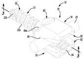
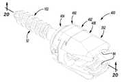
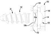
도 1 내지 도 8을 참조하여, 다중평면 뼈 앵커 시스템(10)이 도시된다. 다중평면 뼈 앵커 시스템(10)은 특히 척추 고정 절차에 맞춰질 수 있다. 하지만, 본 발명의 다양한 양상들은 다른 절차들을 위한 적용을 가질 수 있다. 어떠한 적용에서, 다중평면 뼈 앵커 시스템(10)은 척추의 후방 영역에서 하나 이상의 척추뼈 또는 척추체(V)(도 1)에 연결될 수 있다. 다중평면 뼈 앵커 시스템(10)은 뼈 맞물림 부재 또는 뼈 패스너(bone fastener)(12), 잠금 부재 또는 잠금 링(lock ring)(14)(도 3), 다중평면 연결 장치(arrangement) 또는 시스템(16)(도 3), 및 튤립 헤드 또는 새들(saddle)(18)을 포함할 수 있다.With reference to FIGS. 1-8, a multiplane
여기서 더 상세하게 논의될 것인 바와 같이, 다중평면 연결 시스템(16)은 새들(18)이 다중 평면들에서 뼈 패스너(12)에 대하여 이동하는 것을 가능하게 할 수 있다. 일반적으로, 새들(18)은 연결 장치 또는 로드(20)를 수용하도록 구성될 수 있고, 이는 예시적인 척추 고정 절차에서 다중 뼈 앵커 시스템(10)을 상호연결하는 데에 사용될 수 있다(도 1). 다중평면 연결 시스템(16)을 사용함으로써, 새들(18)은 하나 이상의 평면에서 뼈 패스너(12)에 대하여 이동될 수 있어 다중 뼈 앵커 시스템(10)에 연결 로드(20)의 연결을 용이하게 한다. 이런 점에서, 환자의 척추체(V)들은 각각의 척추체(V)에 연결될 때, 각각의 뼈 패스너(12)가 상호 간에 약간 오프셋될(offset) 수 있는 방식으로 배향될 수 있다. 새들(18)이 뼈 패스너(12)에 대하여 다중 평면들에서 이동하도록 함으로써, 외과의사는 뼈 패스너(12)들의 배치에 대하지 않고 새들(18)들을 정렬로 이동시킬 수 있다. 하지만, 비록 다중평면 뼈 앵커 시스템(10)이 일반적으로 여기서 도시되고 설명되더라도, 연결 로드(20)들 및 뼈 앵커 시스템(10)들의 어떠한 조합, 단일 연결 로드(20)와 함께 사용을 위한 단일 어셈블리가 수술 절차 동안에 채택될 수 있다는 것이 언급되어야 한다.As will be discussed in more detail herein, the
예를 들어, 단일 레벨 척추 고정 절차에서, 2개의 뼈 앵커 시스템(10)들은 단일 연결 로드(20)를 수용할 수 있다. 하지만, 다중 레벨 척추 고정 절차는 일반적으로 추가적인 뼈 앵커 시스템(10)들을 필요로 할 것이다. 게다가, 다중평면 뼈 앵커 시스템(10)들은 인접한 척추체(V)들에 연결될 필요가 없는 것이 아니라, 오히려 요구된다면, 다중평면 뼈 앵커 시스템(10)들은 인접한 척추체(V)들을 건너뛰도록 위치될 수 있다.For example, in a single level spinal fixation procedure, two
도 2 내지 도 4를 참조하여, 뼈 패스너(12)는 해부 구조에 맞물려 해부 구조에 다중평면 뼈 앵커 시스템(10)을 연결시키도록 구성될 수 있다. 뼈 패스너(12)는 어떠한 적절한 생체에 적합한 재료, 예를 들어 티타늄, 스테인리스 스틸, 생체에 적합한 폴리머 등으로 구성될 수 있다. 뼈 패스너(12)는 도 3과 도 4를 참조하여 근위단(proxiaml end) 또는 헤드(30)(도 3과 도 4) 및 원위단(distal end) 또는 섕크(shank)(32)(도 2)를 포함할 수 있고, 헤드(30)는 일반적으로 아치형일 수 있고, 드라이버 연결 구조체(34) 및 채널(36)을 포함할 수 있다. 드라이버 연결 구조체(34)는 펜타로브(pentalobe), 헥사로브(hexalobe), 헥사곤(hexagon), 톡스(torx), 필립스(Philips), 십자형, 직선형 등과 같은 드라이버를 위한 어떠한 대응 연결 인터페이스(mating connecting interface)를 포함할 수 있다. 따라서, 드라이버 연결 구조체(34)는 토크의 적용이 뼈 패스너(12)를 해부 구조 안으로 구동시키는 것을 가능하게 할 수 있다.With reference to FIGS. 2-4,
간략하게, 다중평면 뼈 앵커 시스템(10)과 함께 사용을 위한 특정한 도구들은 본 발명의 범위를 넘어 존재하고, 여기서 설명되는 것을 필요로 하지 않는다는 것이 언급되어야 한다. 본 발명이 관련되는 한 종래 방식에서, 다양한 도구들이 각각의 척추체(V)에 다중평면 뼈 앵커 시스템(10)을 연결하는 데에 사용될 수 있다. 예시적인 도구는 인디애나, 워소의 바이오멧, Inc.로부터 상업적으로 이용가능한, Polaris™ 5.5 척추 시스템에 채택된 도구, 또는 2007년 4월 20일에 출원되고 여기서 참조에 의해 포함된, 공유 미국 공개 특허 2008/0077138호에서 개시된 도구를 포함할 수 있다.Briefly, it should be mentioned that certain tools for use with the multiplane
도 3과 도 4를 지속적으로 참조하여, 채널(36)은 헤드(30)의 원주를 중심으로 한정될 수 있다. 채널(36)은 새들(18)이 뼈 패스너(12)의 길이방향 축(L)을 중심으로 회전하는 것을 가능하게 하도록 다중 연결 시스템(16)의 일부를 수용할 수 있다. 따라서, 채널(36)은 제 1 베어링 표면(36a)을 한정할 수 있다. 비록 뼈 패스너(12)가 채널(36)을 포함하는 것으로써 여기서 도시되고 설명되더라도, 채널(36)은 새들(18)이 뼈 패스너(12)의 길이방향 축(L)을 중심으로 회전하는 것을 가능하게 한다는 것을 필요할 필요가 없다.With continued reference to FIGS. 3 and 4,
도 2를 참조하여, 뼈 패스너(12)의 섕크(32)는 복수 개의 쓰레드(thread)(32a)들 및 적어도 하나의 절단 플루트(32b)를 포함할 수 있다. 적어도 하나의 절단 플루트(32b)는 쓰레드(32a)들과 상호작용하여 해부 구조로 절단하고, 이에 따라, 뼈 패스너(12)는 미리-나사 구멍(pre-tapped hole)을 요구하지 않는다. 비록 뼈 패스너(12)가 적어도 하나의 절단 플루트(32b)를 포함하는 것으로써 여기서 도시되고 설명되더라도, 요구된다면, 뼈 패스너(12)는 다중 절단 플루트들을 포함할 수 있거나, 또는 (미리-나사 구멍을 요구하는)어떠한 절단 플루트들을 포함할 필요가 없다.Referring to FIG. 2, the
도 3과 도 4를 참조하여, 잠금 링(14)은 뼈 패스너(12)의 헤드(30) 주위에 위치될 수 있다. 여기서 논의될 것인 바와 같이, 잠금 링(14)은 연결 로드(20)에 적용된 힘을 통해 새들(18)에 대하여 다중 연결 시스템(16) 및 뼈 패스너(12) 중 적어도 하나를 고정시킬 수 있다. 잠금 링(14)은 일반적으로 실린더형일 수 있고, 높이(H)를 가질 수 있다. 높이(H)는 새들(18)에 연결 로드(20)를 연결하는 것이 뼈 패스너(12)의 헤드(30) 상으로 잠금 링(13)을 압축시킬 수 있도록 새들(18)의 리시버 표면(receiver surface)(88)을 넘어 연장되는 크기가 될 수 있다. 도 4를 참조하여, 잠금 링(14)은 근위단(40), 원위단(42), 베어링 표면(44), 슬롯(slot)(46) 및 보어(bore)(48)를 포함할 수 있다.3 and 4, the locking
근위단(40)은 환형 돌기(40a)를 포함할 수 있다. 도 3을 참조하여, 돌기(40a)는 잠금 링(14)의 직경(D1)보다 큰, 직경(DP)을 가질 수 있다. 돌기(40a)의 더 큰 직경(DP)은 잠금 링(14)이 뼈 패스너(12)의 헤드(30)를 중심으로 이동하거나 회전하는 것을 가능하게 하는 크기가 될 수 있다. 도 3 내지 도 5를 참조하여, 원위단(42)은 링 또는 플랜지(flange)(42a) 및 적어도 하나의 컷아웃부(cutout)(43)를 포함할 수 있다. 여기서 더 상세하게 논의될 것인 바와 같이, 플랜지(42a)는 잠금 링(14)의 외부 표면 주위에 형성될 수 있고, 새들(18) 내에 잠금 링(14)을 유지시킬 수 있다. 적어도 하나의 컷아웃부(43)는 잠금 링(14)의 원주의 일부를 따라 형성될 수 있고, 다중평면 연결 시스템(16)과 상호작용하는 크기가 될 수 있다.The
일 실시예에서, 잠금 링(14)은 2개의 컷아웃부(43)들을 포함할 수 있고, 이는 잠금 링(14)의 반대측 상에 위치될 수 있다(도 4). 본 실시예에서, 도 5에서 최상으로 도시된 바와 같이, 컷아웃부(43)는 크기와 형태가 동일할 수 있는 제 1 곡선 리세스(curved recess)(43a), 제 2 곡선 리세스(43b) 및 제 3 곡선 리세스(43c)를 포함할 수 있다. 컷아웃부(43)들은 일반적으로 잠금 링(14)의 길이방향 축을 중심으로 대칭일 수 있다. 제 1 곡선 리세스(43a) 및 제 3 곡선 리세스(43c)는 원위단(42)으로부터 플랜지(42a)까지 형성될 수 있다. 제 2 곡선 리세스(43b)는 원위단(42)으로부터 플랜지(42a)에 인접한 위치까지 형성될 수 있다. 게다가, 제 2 곡선 리세스(43b)는 제 1 곡선 리세스(43a) 및 제 3 곡선 리세스(43c)의 각각에 연관된 반경보다 클 수 있는 반경을 가질 수 있다.In one embodiment, the
도 3 및 도 4를 참조하여, 베어링 표면(44)은 잠금 링(14)의 내부 표면 상에 형성될 수 있다. 일 실시예에서, 베어링 표면(44)은 잠금 링(14)의 원위단(42)으로부터 돌기(40a)의 내부 표면을 따라 형성될 수 있다. 베어링 표면(44)은 일반적으로 오목 영역을 포함할 수 있고, 이는 돌기(40a)의 원주로부터 연장될 수 있다. 베어링 표면(44)은 잠금 링(14)이 뼈 패스너(12)에 대하여 이동하거나 관절로 이어지는 것(articulate)을 가능하게 하도록 헤드(30)의 일부와 접촉할 수 있다. 여기서 도시될 것인 바와 같이, 베어링 표면(44)은 또한 잠금 링(14)이 다중평면 연결 시스템(16)에 대하여 이동하거나 관절로 이어지는 것을 가능하게 할 수 있다.3 and 4, the bearing
도 4를 참조하여, 잠금 링(14)은 또한 슬롯(46)을 포함할 수 있다. 슬롯(46)은 돌기(40a), 근위단(40) 및 원위단(42)을 통해 연장될 수 있다. 슬롯(46)은 잠금 링(14)이 뼈 패스너(12)의 헤드(30) 주위에 연결되는 것을 가능하게 할 수 있다. 슬롯(46)이 선택적이고, 잠금 링(14)이 잠금 링(14)의 원주 주위에서 연속적일 수 있다는 것을 언급한다.Referring to FIG. 4, the
도 3을 참조하여, 보어(48)는 잠금 링(14)의 중심축 주위에 위치될 수 있다. 보어(48)는 돌기(40a), 근위단(40) 및 원위단(42)을 통해 연장될 수 있다. 돌기(40a)에서 보어(48)의 제 1 직경(D1)은 잠금 링(14)의 원위단(42)에서 보어(48)의 제 2 직경(D2)보다 실질적으로 작을 수 있다. 베어링 표면(44)은 보어(48) 주위에 형성될 수 있고, 제 1 직경(D1)으로부터 제 2 직경(D2)으로 보어(48)를 전이시킬 수 있다. 보어(48)는 드라이버가 뼈 패스너(12)의 헤드(30) 상에 형성된 드라이버 연결 구조체(34)와 접촉하는 것을 가능하게 할 수 있다.Referring to FIG. 3, the
일 실시예에서, 다중평면 연결 시스템(16)은 링(50)을 포함할 수 있다. 도 3에 도시된 바와 같이, 링(50)은 뼈 패스너(12)가 새들(18)에 대하여 이동하거나 관절로 이어지는 것을 가능하게 하도록 뼈 패스너(12)의 헤드(30) 주위에 위치될 수 있다. 도 6과 도 7에 도시된 바와 같이, 링(50)은 환형일 수 있고, 뼈 패스너(12)가 새들(18)에 대하여 관절로 이어지는 것을 가능하게 하도록 새들(18) 내에 맞춰지는 크기가 될 수 있다. 도 4를 참조하여, 링(50)은 보어(52) 및 적어도 하나의 윙(54)을 포함할 수 있다. 보어(52)는 링(50)이 뼈 패스너(12)의 채널(36)에 연결되는 것을 가능하게 하는 크기가 될 수 있으나, 또한 도 3에서 최상으로 도시된 바와 같이, 링(50)이 뼈 패스너(12)의 헤드(30)를 넘어 이동하는 것을 방지하는 크기가 될 수 있다.In one embodiment, the
도 4와 도 5를 참조하여, 적어도 하나의 윙(54)은 링(50)의 원주로부터 외측으로 연장될 수 있다. 일 실시예에서, 링(50)은 2개의 윙(54)들을 포함할 수 있다. 윙(54)들은 링(50)의 반대측으로부터 외측으로 연장될 수 있다. 윙(54)들은 뼈 패스너(12)가 새들(18)에 대하여 이동하거나 관절로 이어지는 것을 가능하게 하도록 새들(18)과 상호작용할 수 있다(도 7). 윙(54)들은 제 1 아치형 표면(54a), 제 2 아치형 표면(54b), 제 3 아치형 표면(54c), 제 4 아치형 표면(54d), 제 5 아치형 표면(54e), 및 제 6 아치형 표면(54f)을 포함할 수 있다. 윙(54)들이 뼈 패스너(12)가 새들(18)에 대하여 회전하는 것을 가능하게 하는 어떠한 형상, 예를 들어, 타원, 원형, 둥근(rounded) 사각형, 둥근 직사각형 등을 가질 수 있기에, 여기서 설명되고 도시된 윙(54)들의 형상은 단지 예시적이다는 것이 언급되어야 한다.4 and 5, at least one
제 1 아치형 표면(54a)은 제 4 아치형 표면(54d) 반대편에 존재할 수 있고, 제 2 아치형 표면(54b)은 제 5 아치형 표면(54e) 반대편에 존재할 수 있으며, 제 3 아치형 표면(54c)은 제 6 아치형 표면(54e) 반대편에 존재할 수 있다. 일반적으로, 제 2 아치형 표면(54b) 및 제 5 아치형 표면(54e)은 제 1 아치형 표면(54a), 제 4 아치형 표면(54d), 제 3 아치형 표면(54c), 및 제 6 아치형 표면(54f) 사이에 위치될 수 있다. 제 1 아치형 표면(54a), 제 2 아치형 표면(54b), 및 제 3 아치형 표면(54c) 각각은 제 1 곡선 리세스(43a), 제 2 곡선 리세스(43b) 및 제 3 곡선 리세스(43c) 중 하나와 각각 접촉할 수 있고, 이는 도 5에서 최상으로 도시된 바와 같이, 잠금 링(14)이 링(50)에 대하여 이동하거나 관절로 이어지는 것을 가능하게 할 수 있다. 도 6과 도 7에 도시된 바와 같이, 제 4 아치형 표면(54d), 제 5 아치형 표면(54e), 및 제 6 아치형 표면(54f)은 뼈 패스너(12)가 새들(18)에 대하여 이동하거나 관절로 이어지는 것을 가능하게 하도록 새들(18)과 상호작용할 수 있다.The first
도 4 및 도 6 내지 도 8을 참조하여, 새들(18)은 제 1 부분 또는 바닥부(bottom portion)(60) 및 제 2 부분 또는 상면부(top portion)(62)를 포함할 수 있다. 상면부(62)는 바닥부(60)에 대하여 이동할 수 있거나 평행이동할 수 있다(도 8). 도 4 및 도 6 내지 도 8을 참조하여, 바닥부(60)는 제 1 종단 또는 근위단(64), 제 2 종단 또는 원위단(66), 보어(68) 및 베어링 표면(70)을 포함할 수 있다. 근위단(64)은 일반적으로 직사각형일 수 있고, 둥근 코너들을 포함할 수 있다. 근위단(64)은 상면부(62)에 연결될 수 있다(도 8). 근위단(64)은 적어도 하나의 레일(64a)을 한정할 수 있다. 일반적으로 상면부(62)는 적어도 하나의 레일(64a)을 따라 이동하거나 평행이동할 수 있다(도 8). 일 실시예에서, 근위단(64)은 2 개의 레일(64a)들을 한정할 수 있고, 이는 바닥부(60)의 반대측 상에 위치될 수 있다. 논의될 것인 바와 같이, 잠금 링(14)의 직경(DP)의 바닥부(60)에 대하여 상면부(62)의 평행이동을 한정하거나 제한할 수 있다. 근위단(64)은 원위단(66)까지 테이퍼할(taper) 수 있다.4 and 6 through 8, the
새들(18)이 뼈 패스너(12)에 연결될 때, 원위단(66)은 뼈 패스너(12)의 섕크(32)에 인접할 수 있다. 도 3에서 최상으로 도시된 바와 같이, 원위단(66)은 내부 표면 상에 립(lip) 또는 스톱(stop)(66a)을 한정할 수 있다. 본 실시예에서, 스톱(66a)은 바닥부(60)의 보어(68)로 연장될 수 있다. 스톱(66a)은 보어(68)의 원주 주위에서 연장될 수 있고, 새들(18)에 대한 뼈 패스너(12)의 운동 또는 관절을 제한할 수 있다.When the
보어(68)는 바닥부(60)를 통해 한정될 수 있다. 보어(68)는 그 안에서 링(50), 잠금 링(15) 및 뼈 패스너(12)를 수용하도록 크기가 될 수 있다. 도 3을 참조하여, 보어(68)는 베어링 표면(68a) 및 측벽(68b)을 포함할 수 있다. 베어링 표면(68a)은 잠금 링(14)의 플랜지(42a)를 수용하여 새들(18)에 잠금 링(14)을 연결시키도록 구성될 수 있다. 다시 말해서, 잠금 링(14)의 플랜지(42a)는 잠금 링(14)이 새들(18)로부터 이동하는 것을 방지하도록 바닥부(60)의 베어링 표면(68a)과 상호작용할 수 있다. 보어(68)의 측벽(68b)은 베어링 표면(70)의 일부를 포함할 수 있다.
베어링 표면(70)은 보어(68)의 원주 주위에서 한정될 수 있다. 일 실시예에서, 보어(68)의 측벽(68a)의 일부(70b), 및 스톱(66a)의 일부(70a) 상에 형성될 수 있다. 도 7에서 최상으로 도시된 바와 같이, 베어링 표면(70)은 일반적으로 링(50)과 상호작용하여 링(50)이 새들(18)의 바닥부(60) 내에서 이동하거나 관절로 이어지는 것을 가능하게 하도록 형상화될 수 있다. 링(50)과 바닥부(60) 사이의 상대 이동은 뼈 패스너(12)가 뼈 패스너(12)의 중심축 또는 길이방향 축을 중심으로 선회하거나 관절로 이어지도록 할 수 있다.Bearing
도 3, 도 4 및 도 8을 참조하여, 새들(18)의 상면부(62)가 바닥부(60)에 대하여 이동할 수 있도록 바닥부(60)의 근위단(64)의 레일(64a)에 연결될 수 있다. 상면부(62)는 실질적으로 U자 형상일 수 있고, 다중평면 뼈 앵커 시스템(10)에 의해 한정된 길이방향 축(L2)에 대하여 대칭일 수 있다(도 8). 상면부(62)는 제 1 종단 또는 근위단(76) 및 제 2 종단 또는 원위단(78)을 포함할 수 있다. 일 실시예에서, 근위단(76)은 제 1 아암(arm)(80) 및 제 2 아암(82)을 포함할 수 있다. 제 1 아암(80) 및 제 2 아암(82)은 U자 형상을 한정하기 위하여 원위단(78)으로부터 상측으로 연장될 수 있다. 제 1 아암(80) 및 제 2 아암(82)의 각각은 대응부(mating portion)(84) 및 캐비티(cavity)(86)를 포함할 수 있다.3, 4, and 8, the
대응부(84)는 조임 메커니즘을 수용하여 새들(18)에 연결 로드(20)를 연결시키도록 구성될 수 있다. 예를 들어, 대응부(84)는 복수 개의 쓰레드들을 포함할 수 있고, 이는 제 1 아암(80) 및 제 2 아암(82)의 각각의 외부 표면(80b, 82b)에 형성될 수 있다. 본 실시예에서, 대응부(84)는 새들(18)에 연결 로드(20)를 연결시키도록 멈춤 나사(set screw)(22) 상에 형성된 쓰레드들에 맞물릴 수 있다. 하지만, 근위단(76)은 새들(18)에 연결 로드(20)를 연결시키는 어떠한 적절한 구성, 예를 들어, 쐐기부, 치아 등을 가질 수 있다.The
캐비티(86)는 제 1 아암(80) 및 제 2 아암(82)의 내부 표면(80b, 82b) 각각에서 한정될 수 있다. 캐비티(86)는 새들(18)의 바닥부(60)에 대하여 상면부(62)의 이동 또는 관절을 위한 클러어런스(clearance)를 제공할 수 있다. 이런 점에서, 캐비티(86)는 상면부(62)가 잠금 링(14)의 일부를 걸쳐 이동하도록 한정될 수 있고, 이는 바닥부(60)에 대하여 상면부(62)를 위한 운동의 범위를 제공할 수 있다. 따라서, 잠금 링(14)과 캐비티(86) 사이의 접촉은 스톱으로서 작용할 수 있어 바닥부(60)에 대하여 상면부(62)의 이동 또는 평행이동을 제한하지만, 다른 기술들이 바닥부(60)에 대하여 상면부(62)의 이동 또는 평행이동을 중단시키거나 제한하는 데에 사용될 수 있다.The
도 4를 참조하여, 상면부(62)의 원위단(78)은 일반적으로 직사각형일 수 있고, 제 1 표면 또는 리시버 표면(receiver surface)(88), 제 2 표면 또는 바닥 표면(90), 및 중심 보어(92)를 포함할 수 있다. 리시버 표면(88)은 연결 로드(20)의 일부를 수용할 수 있다. 일 구체예에서, 리시버 표면(88)은 일반적으로 새들(18)의 U자 형상을 형성하는 아치형 오목 표면을 포함할 수 있지만, 리시버 표면(88)은 어떠한 원하는 형상, 예를 들어, 사각형 등을 포함할 수 있다.Referring to FIG. 4, the
바닥 표면(90)은 적어도 하나 이상의 가이드(90a)를 포함할 수 있다. 본 실시예에서, 바닥 표면(90)은 2 개의 가이드(90a)들을 포함할 수 있다. 가이드(90a)들은 바닥부(60)에 상면부(62)를 슬라이딩가능하게 연결시킬 수 있다. 이런 점에서, 각각의 가이드(90a)는 새들(18)의 상면부(62)가 새들(18)의 바닥부(60)에 대하여 이동하거나 평행이동하는 것을 가능하도록 각각 레일(44a)들 중 하나와 상호작용할 수 있다(도 8). 일반적으로, 각각의 가이드(90a)는 C자 형상을 포함할 수 있고, 각각의 레일(44a)은 가이드(90a)의 중심 내에 수용될 수 있다. 하지만, 어떠한 적절한 형상이 상면부(62)가 바닥부(60)에 대하여 이동하거나 평행이동하는 것을 가능하게 하는 데에 사용될 수 있다는 것이 이해되어야 한다.The
중심 보어(92)는 리시버 표면(88)으로부터 바닥 표면(90)까지 원위단(78)을 통해 한정될 수 있다. 일반적으로, 중심 보어(92)는 뼈 패스너(12)를 수용하는 크기가 될 수 있고, 뼈 패스너(12)가 요구된 평면들에서 이동하도록 다중평면 연결 시스템(16)과 상호작용할 수 있다.Center bore 92 may be defined through
도 2와 도 3을 참조하여, 연결 로드(20)는 새들(18)의 리시버 표면(88) 내에 수용될 수 있다. 연결 로드(20)는 적절한 기계적 패스너, 예를 들어 세트 멈춤 나사(22)를 통해 새들(18)에 연결될 수 있다. 예시적인 연결 로드(20) 및 멈춤 나사(22)는 인디애나, 워소의 바이오멧, Inc.로부터 상업적으로 이용가능한, Polaris™ 5.5 척추 시스템에 채택된 연결 로드 및 멈춤 나사, 또는 2007년 4월 20일에 출원되고 여기서 참조에 의해 이전에 포함된, 공유 미국 공개 특허 2008/0077138호에서 개시된 연결 요소와 실질적으로 유사할 수 있다. 연결 로드(20) 및 멈춤 나사(22)가 일반적으로 공지될 수 있기에, 연결 로드(20) 및 멈춤 나사(22)는 여기서 더 상세하게 논의되지 않을 것이다.With reference to FIGS. 2 and 3, the connecting
하지만, 간략하게, 연결 로드(20)는 가늘고 긴 고체 실린더를 포함할 수 있다. 연결 로드(20)는 또한 약간의 곡률을 포함할 수 있고, 이는 척추의 자연 곡률에 상응할 수 있다. 일반적으로, 연결 로드(20)는 상호 간에 대하여 척추체(V)들을 고정시키는 데 충분한 강성을 갖는 적절한 생체에 적합한 재료로 구성될 수 있다. 멈춤 나사(22)는 쓰레드들을 포함할 수 있고, 이는 새들(18)의 근위단(76)의 대응부(84)에 형성된 쓰레드들에 대응하게 맞물릴 수 있다.In brief, however, the connecting
도 4 내지 도 8을 참조하여, 다중평면 뼈 앵커 시스템(10)을 조립하기 위하여, 링(50)은 뼈 패스너(20)의 채널(36) 주위에 위치될 수 있다(도 5). 이어서, 새들(18)의 바닥부(60)는 링(50) 주위에 위치될 수 있다(도 6과 도 7). 잠금 링(14)은 상면부(62)에 연결될 수 있다. 다음으로, 새들(18)의 상면부(62)는 새들(18)의 바닥부(60)에 연결될 수 있다(도 8). 이어서, 잠금 링(14)은 뼈 패스너(12)의 헤드(30)에 연결될 수 있다.With reference to FIGS. 4-8, to assemble the multiplanar
일단 조립된다면, 링(50)은 뼈 패스너(12)의 회전 또는 이동이 뼈 패스너(12)의 중심축 또는 길이방향 축을 중심으로 가능하게 하도록 바닥부(60)와 상호작용할 수 있다(도 6과 도 7). 잠금 링(14)은 뼈 패스너(12)가 뼈 패스너(12)의 헤드(30)를 중심으로, 새들(18)에 대하여 이동하거나 관절로 이어지는 것을 가능하게 하도록 뼈 패스너(12)의 헤드(30)와 상호작용할 수 있다(도 5). 새들(18)의 상면부(62)는 새들(18)의 상면부(62)가 새들(18)의 바닥부(60)에 대하여 이동하거나 평행이동하는 것을 가능하도록 바닥부(60)와 상호작용할 수 있다(도 8). 따라서, 조립될 때, 다중평면 뼈 앵커 시스템(10)은 적어도 3도의 운동(degree of movement)을 가질 수 있거나, 또는 적어도 3개의 평면들에서 이동가능할 수 있다. 다중평면 뼈 앵커 시스템(10)이 적어도 3개의 평면들에서 이동하도록 함으로써, 외과의사는 환자의 해부 구조에 일치시키는 데 필요하기에 다중평면 뼈 앵커 시스템(10)을 조작할 수 있다.Once assembled, the
다중평면 연결 시스템(16)을 통해 새들(18)에 연결된 뼈 패스너(12)로, 수술 이용은 중요한 척추체(V)들에 인접한 피부(S)를 통해 이루어질 수 있다(도 1). 특정한 수술 접근법은 인디애나, 워소의 바이오멧, Inc.로부터 상업적으로 이용가능한, Polaris™ 5.5 척추 시스템과 함께 사용된 것과 같은 최소로 절개하는 수술 절차, 또는 여기서 참조에 의해 이전에 포함된, 2007년 4월 20일에 출원된 공유 미국 공개 특허 2008/0077138호에서 개시된 최소로 절개하는 수술 절차를 통해 획득될 수 있다.With
다음으로, 하나 이상의 다중평면 뼈 앵커 시스템(10)은 뼈 패스너(12)를 통해 각각의 척추체(V)에 연결될 수 있다(도 1). 다양한 기술은 여기서 참조에 의해 이전에 포함된, 2007년 4월 20일에 출원된 공유 미국 공개 특허 2008/0077138호에서 설명된 것과 같은, 해부 구조에 다중평면 뼈 앵커 시스템(10)을 연결시키는 데에 사용될 수 있다. 일 구체예에서, 만약 각각의 뼈 패스너(12)가 헤드(30)에 한정된 드라이버 연결 구조체(34)를 포함한다면, 적절한 도구는 종래의 방식으로 해부 구조 안으로 뼈 패스너(12)를 구동시키도록 드라이버 연결 구조체(34)에 연결될 수 있다. 일단 다중평면 뼈 앵커 시스템(10)이 해부 구조에 연결된다면, 연결 로드(20)는 다중평면 뼈 앵커 시스템(10)들의 각각의 새들(18) 안으로 삽입될 수 있다. 일반적으로, 연결 로드(20)는 연결 로드(20)가 새들(18)의 원위단(78)의 리시버 표면(88) 상에 정지되도록 삽입될 수 있다(도 2).Next, one or more multiplanar
다중평면 뼈 앵커 시스템(10)의 새들(18)에 위치되는 연결 로드(20)로, 멈춤 나사(22)는 각각의 새들(18)의 각각의 대응부(68)에 연결될 수 있다(도 3). 멈춤 나사(22)의 연결은 새들(18)에 대하여 뼈 패스너(12)의 각도 위치를 고정되게 연결시키거나 고정시키도록 잠금 링(14)에 힘을 적용시킬 수 있다. 이런 점에서, 잠금 링(14)은 뼈 패스너(12)의 헤드(30)에 힘을 적용시킬 수 있고, 이는 결국, 링(50) 상에 힘을 제공할 수 있다. 게다가, 잠금 링(14)은 링(50)에 직접 힘을 적용시킬 수 있다. 링(50) 상의 힘은 결국 새들(18)의 바닥부(60)에 적용될 수 있어, 이에 의해 새들(18)에 대하여 뼈 패스너(12)의 위치를 고정시킨다.With a connecting
도 9 내지 도 11을 참조하여, 일 구체예에서, 다중평면 뼈 앵커 시스템(100)은 연결 로드(20)와 함께 채택될 수 있어 해부 구조의 손상된 부분을 보수한다. 다중평면 뼈 앵커 시스템(100)이 도 1 내지 도 8를 참조하여 설명된 다중평면 뼈 앵커 시스템(10)과 유사할 수 있기에, 다중평면 뼈 앵커 시스템(10)과 다중평면 뼈 앵커 시스템(100) 사이의 차이만이 여기서 더 상세하게 논의될 것이고, 동일한 참조번호들은 동일하거나 유사한 구성요소들을 나타내는 데에 사용될 것이다. 다중평면 뼈 앵커 시스템(100)은 뼈 패스너(102), 다중평면 연결 장치 또는 시스템(104) 및 새들(106)을 포함할 수 있다. 비록 다중평면 뼈 앵커 시스템(100)이 잠금 링(14)을 포함하지 않는 것으로서 여기서 설명되고 도시되더라도, 요구된다면, 적절한 잠금 링(14)이 다중평면 뼈 앵커 시스템(100)과 함께 채택될 수 있다는 것이 언급되어야 한다.9-11, in one embodiment, the multiplanar
도 9 내지 도 11을 참조하여, 뼈 패스너(102)는 해부 구조에 맞물려 해부 구조에 다중평면 뼈 앵커 시스템(100)을 연결시키도록 구성될 수 있다. 뼈 패스너(102)는 어떠한 적절한 생체에 적합한 재료, 예를 들어 알루미늄, 스테인리스 스틸, 생체에 적합한 폴리머 등으로 구성될 수 있다. 뼈 패스너(102)는 헤드(108) 및 섕크(32)를 포함할 수 있다. 헤드(108)는 일반적으로 아치형일 수 있고, 드라이버 연결 구조체(34) 및 채널(108a)을 포함할 수 있다.9-11, the
채널(108a)은 일반적으로 헤드(108)와 섕크(32) 사이의, 헤드(108)의 원주 주위에서 한정될 수 있다. 채널(108a)은 새들(106)이 뼈 패스너(102)의 길이방향 축(L)을 중심으로 회전하는 것을 가능하게 하도록 다중평면 연결 시스템(104)의 일부를 수용할 수 있다(도 10). 따라서, 채널(108a)은 제 1 베어링 표면을 한정할 수 있다. 비록 뼈 패스너(102)가 채널(108a)을 포함하는 것으로서 여기서 도시되고 설명되더라도, 채널(108a)은 새들(106)이 뼈 패스너(102)의 길이방향 축(L)을 중심으로 회전하는 것을 가능하게 한다는 것을 필요할 필요가 없다는 것이 언급되어야 한다.
일 구체예에서, 도 9 내지 도 11을 지속적으로 참조하여, 다중평면 연결 시스템(104)은 연결 아암(110) 및 베어링 부재 또는 링(112)을 포함할 수 있다. 연결 아암(110) 및 링(112)은 뼈 패스너(102)가 새들(106)에 대하여 이동하는 것을 가능하게 하도록 뼈 패스너(102)와 상호작용할 수 있다. 도 11에 도시된 바와 같이, 연결 아암(110)은 뼈 패스너(102)가 새들(106)에 대하여 이동하거나 관절로 이어지는 것을 가능하게 하도록 뼈 패스너(102)의 헤드(108) 주위에 위치될 수 있다. 본 실시예에서, 연결 아암(110)은 환형일 수 있고, 새들(106)에 연결될 수 있다. 연결 아암(110)은 보어(114)를 포함할 수 있다. 보어(114)는 연결 아암(110)의 중심축(C) 주위에 형성될 수 있다. 도 11에서 최상으로 도시된 바와 같이, 보어(114)는 대응부(114a), 리세스(recess)(114b), 연결부(114c) 및 테이퍼부(tapered portion)(114d)를 포함할 수 있다.In one embodiment, with continued reference to FIGS. 9-11, the
대응부(114a)는 새들(116)에 연결 아암(110)을 연결시킬 수 있다. 대응부(114a)는 새들(106)이 연결 아암(110)에 대하여 이동할 수 있거나 평행이동할 수 있도록 구성될 수 있다는 것이 언급되어야 한다. 예를 들어, 대응부(114a)는 슬라이딩가능하게 새들(106)의 일부를 수용할 수 있는 연결 아암(110)의 일부를 통해 형성된 반대하는 가이드들 또는 슬롯들을 포함할 수 있다. 하지만, 어떠한 적절한 방법 또는 구성, 예를 들어 열장이음(dovetail), 레일들이 연결 아암(110)에 새들(106)을 슬라이딩가능하게 연결시키는 데에 사용될 수 있다.The
리세스(114b)는 대응부(114a)와 적어도 하나의 연결부(114c) 사이에서 한정될 수 있다. 일반적으로, 리세스(114b)는 아치형일 수 있고, 일 실시예에서, 반구형일 수 있다. 리세스(114b)는 연결 아암(110) 내에서 연결 아암(110)에 대하여 뼈 패스너(102)의 헤드(108)의 회전을 위한 적어도 클리어런스를 제공할 수 있다. 이런 점에서, 리세스(118)는 뼈 패스너(102)의 길이방향 축(L)을 중심으로 적어도 회전을 가능하게 하는 크기가 될 수 있고, 또한 요구된다면, 뼈 패스너(102)의 헤드(108)를 중심으로 연결 아암(110)의 회전을 가능하게 하는 크기가 될 수 있다.The
연결부(114c)는 리세스(114b)와 테이퍼부(114d) 사이에 한정될 수 있다. 일 실시예에서, 연결부(114c)는 연결 아암(110)의 원주 주위에서 한정된 채널을 포함할 수 있다. 일반적으로, 연결부(114c)는 링(112)을 수용하도록 구성될 수 있고, 이는 여기서 논의될 것인 바와 같이, 연결 아암(110)에 뼈 패스너(102)를 이동가능하거나 회전가능하게 연결시킬 수 있다.The connecting
테이퍼부(114d)는 보어(114)의 최원위단에서 한정될 수 있다. 테이퍼부(114d)는 새들(116)에 대하여 뼈 패스너(102)의 각도 이동을 위한 클리어런스를 제공할 수 있다. 이런 점에서, 테이퍼부(114d)는 보어(114)의 원주 주위에서 형성될 수 있고, 뼈 패스너(102)의 섕크(32)는 연결 아암(110)에 대하여 뼈 패스너의 각도 이동을 제한하도록 테이퍼부(114d)와 접촉할 수 있다. 따라서, 테이퍼부(114d)는 새들(106)에 대하여 뼈 패스너(102)의 각도 이동을 위하여 스톱 또는 리미트(limit)를 제공할 수 있다.The tapered
도 10과 도 11을 참조하여, 링(112)은 뼈 패스너(102)의 헤드(108)의 채널(108a)에 연결될 수 있고, 뼈 패스너(102)가 연결 아암(110)에 대하여 이동하거나 회전하는 것을 가능하게 하도록 보어(114)와 상호작용할 수 있다. 일 실시예에서, 링(112)은 일반적으로 C자 형상 몸체를 포함할 수 있고, 슬롯(112a)을 가질 수 있다. 링(112)은 헤드(108)의 채널(108a) 내에 적어도 부분적으로 수용될 수 있다. 일반적으로, 링(112)은 뼈 패스너(102)의 채널(108a) 안으로 스냅-끼워맞춰질(snap-fit) 수 있다. 일 실시예에서, 링(112)은 헤드(108)의 채널(108a)의 외경보다 클 수 있는 내경을 가질 수 있어 뼈 패스너(102)의 헤드(108) 주위로부터 링(112)의 분리를 방지한다. 하지만, 링(112)은 연속적인 환형체, 예를 들어, O-형상을 가질 수 있고, 이런 경우에, 링(112)은 섕크(32)를 걸쳐 채널(36) 안으로 쓰레딩될(threaded) 수 있다는 것이 언급되어야 한다.With reference to FIGS. 10 and 11, the
도 10을 참조하여, 링(112)은 적어도 하나의 윙(116)을 포함할 수 있다. 적어도 하나의 윙(116)은 보어(114)의 연결부(114c)에 맞물리도록 링(112)의 몸체로부터 외측으로 연장될 수 있다. 본 실시예에서, 링(112)은 2개의 윙(116)들을 포함할 수 있고, 이는 각각 연결 아암(110)의 보어(114)의 연결부(114c) 내에 수용될 수 있고 슬라이딩가능하게 연결될 수 있다. 윙(116)들은 베어링 표면들을 포함할 수 있고, 이는 연결 아암(110)을 중심으로 뼈 패스너(102)의 회전을 가능하게 하도록 연결부(114c)와 상호작용할 수 있다. 따라서, 윙(116)들은 어떠한 형상, 예를 들어 타원형, 구형, 둥근형, 환형, 둥근 사각형, 둥근 직사각형 등을 가질 수 있고, 이는 윙(114)들이 보어(114)의 연결부(114c) 내에서 이동하거나 슬라이딩하는 것을 가능하게 할 수 있다. 윙(116)들은 또한 적어도 하나의 테이퍼진 표면(tapered surface)(116a)을 포함할 수 있고, 이는 연결 아암(110)이 뼈 패스너(102)에 대하여 이동하거나 선회하는 것을 가능하게 할 수 있다. 본 실시예에서, 윙(116)들은 2개의 반대편 테이퍼진 표면(116a)들을 포함할 수 있고, 이는 연결 아암(110)이 뼈 패스너(102)의 헤드(108)를 중심으로 이동하거나 선회하는 것을 가능하게 하도록 연결부(114c)와 상호작용할 수 있다.Referring to FIG. 10, the
도 9 내지 도 11을 참조하여, 새들(106)은 연결 아암(110)을 통해 다중평면 연결 시스템(104)에 연결될 수 있다. 일반적으로, 새들(106)은 새들(106)이 다중평면 연결 시스템(106) 및 뼈 패스너(102)에 대하여 이동할 수 있거나 평행이동할 수 있도록 연결 아암(110)에 연결될 수 있다. 새들(106)은 실질적으로 U자 형상이고 다중평면 뼈 앵커 시스템(100)에 의해 한정된 길이방향 축(L)에 대하여 대칭일 수 있다. 일 실시예에서, 새들(116)은 제 1 종단 또는 근위단(120) 및 제 2 종단 또는 원위단(122)을 포함할 수 있다. 일 실시예에서, 근위단(120)은 제 1 아암(124) 및 제 2 아암(126)을 포함할 수 있다. 제 1 아암(124) 및 제 2 아암(126)은 U자 형상을 한정하기 위하여 원위단(122)으로부터 상측으로 연장될 수 있다. 제 1 아암(124) 및 제 2 아암(126)의 각각은 대응부(84)를 포함할 수 있다.9-11, the
도 10과 도 11을 참조하여, 원위단(122)은 일반적으로 직사각형일 수 있고, 리시버 표면(88)(도 10), 적어도 하나의 레일(122a)(도 11) 및 중심 보어(92)(도 11)를 포함할 수 있다. 일 실시예에서, 원위단(122)은 2개의 레일(122a)들을 포함할 수 있다. 일반적으로, 레일(122a)들은 보어(92)의 반대측들 상에 형성될 수 있고, 보어(92)로부터 외측으로 연장될 수 있다. 레일(122a)들은 연결 아암(110)에 새들(106)을 슬라이딩가능하게 연결시킬 수 있다. 이런 점에서, 각각의 레일(122a)은 새들(106)이 연결 아암(110) 및 뼈 패스너(102)에 대하여 이동하거나 평행이동하는 것을 가능하게 하도록 대응부(114a)의 가이드들 또는 슬롯들 중 각각의 하나와 상호작용할 수 있다. 하지만, 어떠한 적절한 메커니즘, 예를 들어 열장이음 어셈블리 등은 새들(106)이 연결 아암(110)에 대해 이동하거나 평행이동하는 것을 가능하게 하는 데에 사용될 수 있다는 것이 이해되어야 한다. 또한, 요구된다면, 원위단(122)은 하나의 레일(122a)만을 포함할 수 있다. 요구된다면, 새들(106)이 대응부(114a)를 포함할 수 있고, 레일(122a)들이 새들(106)과 연결 아암(110) 사이에서 상대 이동을 가능하게 하도록 연결 아암(110) 상에 형성될 수 있다는 것이 또한 이해될 수 있다.10 and 11, the
도 10과 도 11을 참조하여, 다중평면 뼈 앵커 시스템(100)을 조립하기 위하여, 링(112)은 뼈 패스너(102)의 채널(108a)에 연결될 수 있다. 이어서 링(112)의 윙(116)들이 연결 아암(110)의 연결부(114c) 내에 수용되도록 연결 아암(110)은 링(112)에 연결될 수 있다. 새들(106)은 레일(122a)들이 연결 아암(110)의 대응부(114a)에 슬라이딩가능하게 연결되도록 위치될 수 있다.10 and 11, to assemble the multiplanar
일단 조립된다면, 연결 아암(110)은 뼈 패스너(102)의 중심축 또는 길이방향 축을 중심으로 뼈 패스너(102)의 이동 또는 회전을 가능하게 하도록 링(112)과 상호작용할 수 있고, 이는 제 1 운동 평면을 제공한다. 게다가, 윙(116)들의 테이퍼진 표면(116a)들은 연결 아암(110)이 뼈 패스너(102)의 헤드(108)를 중심으로 뼈 패스너(102)에 대하여 이동하거나 선회하는 것을 가능하게 하도록 연결 아암(110)의 연결부(114c)와 상호작용할 수 있고, 이에 의해 제 2 운동 평면을 제공한다. 새들(106)은 또한 새들(106)이 연결 아암(110)에 대하여 이동하거나 평행이동하는 것을 가능하게 하도록 연결 아암(110)과 상호작용할 수 있고, 이에 의해 제 3 운동 평면을 제공한다. 따라서, 조립될 때, 다중평면 뼈 앵커 시스템(100)은 적어도 3개의 운동 평면들 또는 3도의 운동을 가질 수 있다. 다중평면 뼈 앵커 시스템(100)이 적어도 3개의 평면들에서 이동하도록 함으로써, 외과의사는 환자의 해부 구조에 일치시키는 데 필요하기에 다중평면 뼈 앵커 시스템(100)을 조작할 수 있다.Once assembled, the connecting
고정 절차에서 다중평면 뼈 앵커 시스템(100)의 사용 및 수술 삽입이 고정 절차에서 다중평면 뼈 앵커 시스템(10)의 삽입 및 수술 삽입과 유사할 수 있기에, 다중평면 뼈 앵커 시스템(100)의 사용 및 수술 삽입은 여기서 더 상세하게 논의되지 않을 것이다. 하지만, 간략하게, 일단 다중평면 뼈 앵커 시스템(100)이 해부 구조에 고정된다면, 다중평면 연결 시스템(104) 및 새들(106)은 고정 절차의 요구된 정렬로 뼈 패스너(102)에 대하여 이동되거나, 또는 선회되거나 회전될 수 있다. 일단 정렬된다면, 연결 로드(20)는 요구된 개수의 다중평면 뼈 앵커 시스템(100)들에 연결될 수 있다.The use of the multiplanar
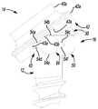
이제 도 12 내지 도 14를 참조하여, 일 실시예에서, 다중평면 뼈 앵커 시스템(200)은 연결 로드(20)와 함께 채택될 수 있어 해부 구조의 손상된 부분을 보수한다. 다중평면 뼈 앵커 시스템(200)은 도 9 내지 도 11을 참조하여 설명된 다중평면 뼈 앵커 시스템(100)과 유사할 수 있기에, 다중평면 뼈 앵커 시스템(100)과 다중평면 뼈 앵커 시스템(200) 사이의 차이만이 여기서 더 상세하게 논의될 것이고, 동일한 참조번호들은 동일하거나 유사한 구성요소들을 나타내는 데에 사용될 것이다. 다중평면 뼈 앵커 시스템(200)은 뼈 패스너(102), 다중평면 연결 장치 또는 시스템(204) 및 새들(206)을 포함할 수 있다.Referring now to FIGS. 12-14, in one embodiment, the multiplanar
도 12 내지 도 14를 참조하여, 다중평면 연결 시스템(204)은 연결 아암(210), 적어도 하나의 플러그(plug)(215) 및 유지 링(retaining ring)(206)을 포함할 수 있다. 연결 아암(210)은 뼈 패스너(102)가 새들(206)에 대하여 이동하는 것을 가능하게 하도록 뼈 패스너(102)와 상호작용할 수 있다. 연결 아암(210)은 뼈 패스너(102)가 새들(206)에 대하여 이동하거나 관절로 이어지는 것을 가능하게 하도록 뼈 패스너(102)의 헤드(108) 주위에 위치될 수 있다. 본 실시예에서, 연결 아암(210)은 환형일 수 있고, 새들(206)에 연결될 수 있다. 연결 아암(210)은 적어도 하나의 연결 구조체(213) 및 보어(214)를 포함할 수 있다. 적어도 하나의 연결 구조체(213)는 연결 아암(210)에 링(215)을 연결시킬 수 있고, 일 실시예에서, 적어도 하나의 연결 구조체(213)는 2개의 연결 구조체(213)들을 포함할 수 있다. 본 실시예에서, 연결 구조체(213)들은 보어들을 포함할 수 있고, 이는 보어(214)에 대하여 연결 아암(210)의 반대측들을 통해 한정될 수 있다. 보어(214)는 연결 아암(210)의 중심축(C) 주위에 형성될 수 있다. 도 14에서 최상으로 도시된 바와 같이, 보어(214)는 대응부(214a), 연결부(114c) 및 테이퍼부(114d)를 포함할 수 있다.12-14, the
대응부(214a)는 새들(206)에 연결 아암(210)을 연결시키도록 유지 링(216)과 상호작용할 수 있다. 일반적으로, 대응부(214a)는 새들(206)이 유지 링(216)을 통해 중심으로 연결 아암에 대하여 이동할 수 있도록 구성될 수 있다. 본 실시예에서, 대응부(214a)는 연결 아암(210)의 일부를 통해 형성된 반대하는 가이드들 또는 슬롯들을 포함할 수 있고, 이는 유지 링(216)의 일부를 슬라이딩가능하게 수용할 수 있다. 하지만, 어떠한 적절한 방법 또는 구성 예를 들어, 열장이음, 레일 등이 연결 아암(210)에 새들(206)을 이동가능하게 연결시키는 데에 사용될 수 있다.Corresponding
도 13을 참조하여, 일 실시예에서, 적어도 하나의 플러그(215a)는 2개의 플러그(215a)들을 포함할 수 있다. 플러그(215a)들은 보어(214)의 연결부(114c)에 맞물릴 수 있다. 본 실시예에서, 플러그(215a)들의 각각은 연결 아암(210)의 보어(214)의 연결부(114c) 내에 수용되고, 이에 슬라이딩가능하게 연결될 수 있다. 플러그(215a)들은 베어링 표면을 포함할 수 있고, 이는 연결 아암(210)을 중심으로 뼈 패스너(102)의 회전을 가능하게 하도록 연결부(114c)와 상호작용할 수 있다. 따라서, 플러그(215a)들은 어떠한 형상, 예를 들어, 타원형, 구형, 둥근형, 환형, 둥근 사각형, 둥근 직사각형 등을 가질 수 있고, 이는 플러그(215a)들이 보어(114)의 연결부(114c) 내에서 이동하거나 슬라이딩하는 것을 가능하게 할 수 있다. 일 실시예에서, 플러그(215a)들은 각각 컷 아웃부(또는 유사한 구조체들)(215b)를 포함할 수 있고, 이는 플러그(215a)들이 연결 아암(210) 안으로 스냅-끼워맞춰지거나 프레스-끼워맞춰지는(press-fit) 것을 가능하게 할 수 있다. 하지만, 요구된다면, 플러그(215a)들은 연결 아암(210)과 일체형으로 형성될 수 있다는 것이 이해되어야 한다. 플러그(215a)들은 연결 아암(210)이 뼈 패스너(102)의 헤드(108)를 중심으로 이동하거나 선회하는 것을 가능하게 하도록 연결부(114c)와 상호작용할 수 있다.Referring to FIG. 13, in one embodiment, at least one
도 14에서 최상으로 도시된 바와 같이, 유지 링(216)은 연결 아암(210)에 새들(206)을 연결시킬 수 있다. 이런 점에서, 유지 링(216)은 제 1 종단 또는 근위단(218) 및 제 2 종단 또는 원위단(220)을 포함할 수 있다. 논의될 것인 바와 같이, 근위단(218)은 새들(206)의 일부에 연결될 수 있고, 원위단(220)은 연결 아암(210)의 대응부(214a)에 연결될 수 있다. 유지 링(216)은 어떠한 적절한 구조물, 예를 들어, 환형 링을 포함할 수 있고, 이는 연속적이고, 중단되지 않는 원주를 포함할 수 있거나 포함하지 않을 수 있다. 본 실시예에서, 유지 링(216)은 C자 형상 링을 포함할 수 있지만, 유지 링(216)은 또한 비-환형 구조물, 예를 들어, 직사각형 구조물, 사각형 구조물 등을 포함할 수 있다는 것이 이해되어야 한다.As best shown in FIG. 14, retaining
유지 링(216)의 근위단(218)은 돌기(218a)를 포함할 수 있고, 이는 새들(206)에 근위단(218)을 연결시킬 수 있다. 원위단(220)은 또한 돌기(220a)를 포함할 수 있고, 이는 대응부(214a)에 원위단(220)을 연결시킬 수 있다. 도 14에서 최상으로 도시된 바와 같이, 원위단(220)의 돌기(220a)는 또한 리세스(220b)를 포함할 수 있다. 리세스(220b)는 뼈 패스너(102)의 헤드(108)가 유지 링(216)과 접촉하지 않고 연결 아암(210)을 중심으로 회전하도록 할 수 있다.
새들(206)은 유지 링(216)을 통해 연결 아암(210)에 연결될 수 있다. 일반적으로, 새들(206)은 새들(206)이 다중평면 연결 시스템(206) 및 뼈 패스너(102)에 대하여 이동할 수 있거나 회전할 수 있도록 연결 아암(210)에 연결될 수 있다. 새들(206)은 실질적으로 U자 형상일 수 있고 다중평면 뼈 앵커 시스템(200)에 의해 한정된 길이방향 축(L)에 대하여 대칭일 수 있다(도 14). 일 실시예에서, 새들(206)은 제 1 종단 또는 근위단(120) 및 제 2 종단 또는 원위단(224)을 포함할 수 있다.The
도 14를 참조하여, 원위단(224)은 일반적으로 환형일 수 있고, 리시버 표면(88), 적어도 하나의 채널(224a) 및 중심 보어(92)를 포함할 수 있다. 본 실시예에서, 원위단(224)은 2개의 채널(224a)들을 포함할 수 있다. 일반적으로 채널(224a)들은 보어(92)의 반대측 상에 형성될 수 있다. 채널(224a)들은 연결 아암(210)에 새들(206)을 연결시킬 수 있다. 이런 점에서, 채널(224a)들은 새들(206)을 연결 아암(210) 및 뼈 패스너(102)에 연결시키도록 유지 링(216)의 원위단(220)의 돌기(220a)를 수용할 수 있다.Referring to FIG. 14, the
도 13과 도 14를 참조하여, 다중평면 뼈 앵커 시스템(200)을 조립하기 위하여, 유지 링(216)은 새들(206)의 채널(224a)들에 연결될 수 있다. 새들(206)에 연결된 유지 링(216)으로, 유지 링(216)의 원위단(220)은 연결 아암(210) 안으로 눌러질 수 있어서, 유지 링(216)의 돌기(216)가 연결 아암(210)의 대응부(214a) 내에 끼워맞춰지도록 한다. 이어서, 연결 아암(210)은 뼈 패스너(102)에 걸쳐 위치될 수 있고, 플러그(215a)들은 플러그(215a)들이 연결 아암(210)의 연결 구조체(213)들을 통해 수용되도록 연결 아암(210)에 연결될 수 있다.With reference to FIGS. 13 and 14, to assemble the multiplanar
일단 조립된다면, 연결 아암(210)은 뼈 패스너(102)의 중심축 또는 길이방향 축을 중심으로 뼈 패스너(102)의 이동 또는 회전을 가능하게 하도록 플러그(215a)들과 상호작용할 수 있고, 이는 제 1 운동 평면을 제공한다. 게다가, 플러그(215a)들은 연결 아암(210)이 뼈 패스너(102)의 헤드(108)를 중심으로 뼈 패스너(102)에 대하여 이동하거나 선회하는 것을 가능하게 하도록 연결 아암(210)의 연결부(114c)와 상호작용할 수 있고, 이에 의해 제 2 운동 평면을 제공한다. 새들(206)은 또한 새들(206)이 연결 아암(210)에 대하여 이동하거나 회전하는 것을 가능하게 하도록 유지 링(216)을 통해 연결 아암(210)과 상호작용할 수 있고, 이는 제 3 운동 평면을 제공할 수 있다. 따라서, 조립될 때, 다중평면 뼈 앵커 시스템(200)은 적어도 3개의 운동 평면들 또는 3도의 운동을 가질 수 있다. 다중평면 뼈 앵커 시스템(200)이 적어도 3개의 평면들에서 이동하도록 함으로써, 외과의사는 환자의 해부 구조에 일치시키는 데 필요하기에 다중평면 뼈 앵커 시스템(200)을 조작할 수 있다.Once assembled, the connecting
고정 절차에서 다중평면 뼈 앵커 시스템(200)의 사용 및 수술 삽입이 고정 절차에서 다중평면 뼈 앵커 시스템(100)의 삽입 및 수술 삽입과 유사할 수 있기에, 다중평면 뼈 앵커 시스템(200)의 사용 및 수술 삽입은 여기서 더 상세하게 논의되지 않을 것이다. 하지만, 간략하게, 일단 다중평면 뼈 앵커 시스템(200)이 해부 구조에 고정된다면, 다중평면 연결 시스템(204) 및 새들(206)은 고정 절차를 위한 요구된 정렬로 뼈 패스너(102)에 대하여 이동되거나, 또는 선회되거나 회전될 수 있다. 일단 정렬된다면, 연결 로드(20)는 요구된 개수의 다중평면 뼈 앵커 시스템(200)들에 연결될 수 있다.The use of the multiplanar
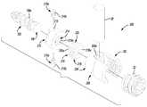
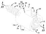
이제 도 15 내지 도 17을 참조하여, 일 실시예에서, 다중평면 뼈 앵커 시스템(300)은 연결 로드(20)와 함께 채택될 수 있어 해부 구조의 손상된 부분을 보수한다. 다중평면 뼈 앵커 시스템(300)은 도 1 내지 도 9를 참조하여 설명된 다중평면 뼈 앵커 시스템(10)과 유사할 수 있기에, 다중평면 뼈 앵커 시스템(300)과 다중평면 뼈 앵커 시스템(10) 사이의 차이만이 여기서 더 상세하게 논의될 것이고, 동일한 참조번호들은 동일하거나 유사한 구성요소들을 나타내는 데에 사용될 것이다. 다중평면 뼈 앵커 시스템(300)은 뼈 패스너(302), 잠금 링(304), 다중평면 연결 장치 또는 시스템(306) 및 새들(307)을 포함할 수 있다.Referring now to FIGS. 15-17, in one embodiment, the multiplanar
도 15와 도 16을 참조하여, 뼈 패스너(302)는 해부 구조에 맞물려 해부 구조에 다중평면 뼈 앵커 시스템(300)을 연결시키도록 구성될 수 있다. 뼈 패스너(302)는 어떠한 적절한 생체에 적합한 재료, 예를 들어 티타늄, 스테인리스 스틸, 생체에 적합한 폴리머 등으로 구성될 수 있다. 뼈 패스너(302)는 근위단 또는 헤드(308) 및 원위단 또는 섕크(32)를 포함할 수 있다. 헤드(308)는 일반적으로 샤프트(308a)를 통해 섕크(32)에 연결된 아치형부 또는 반구형부(308a)를 포함할 수 있다. 반구형부(308a)는 드라이버 연결 구조체(34)를 포함할 수 있다. 다중평면 뼈 앵커 시스템(300)이 조립될 때 반구형부(308a)는 잠금 링(304)에 연결될 수 있다. 샤프트(308b)는 일반적으로 실린더형일 수 있고, 반구형부(308a)로부터 말단으로 연장될 수 있다. 샤프트(308b)는 뼈 패스너(302)에 다중평면 연결 시스템(306)을 연결시키도록 다중평면 연결 시스템(306)의 일부를 수용할 수 있다.15 and 16,
잠금 링(304)은 도 17에서 최상으로 도시된 바와 같이, 뼈 패스너(302)의 헤드(308) 주위에 위치될 수 있다. 여기서 논의될 것인 바와 같이, 잠금 링(304)은 연결 로드(20)에 적용된 힘을 통해 다중평면 연결 시스템(306)에 대하여 뼈 패스너(102)를 연결시킬 수 있거나 고정시킬 수 있다. 잠금 링(304)은 일반적으로 실린더형일 수 있고, 높이(H3)를 가질 수 있다. 높이(H3)는 새들(307)의 리시버 표면(88)을 넘거나 거의 동일하게 연장되는 크기가 될 수 있어서 새들(307)에 연결 로드(20)를 연결시키는 것은 뼈 패스너(302)의 헤드(308) 상으로 잠금 링(304)을 압축시킬 수 있다. 도 16에 도시된 바와 같이, 본 실시예에서, 잠금 링(304)은 컷 아웃부(304a)를 포함할 수 있고, 이는 뼈 패스너(302)의 헤드(308) 주위에 잠금 링(304)을 위치시키는 것을 용이하게 할 수 있다. 하지만, 잠금 링(304)이 연속적이고 중단되지 않는 실린더형 몸체를 가질 수 있기에, 컷 아웃부(304a)가 선택적일 수 있다는 것이 이해되어야 한다. 게다가, 잠금 링(304)은 근위단(310), 원위단(312), 플랜지(314) 및 보어(316)를 포함할 수 있다.The
다중평면 뼈 앵커 시스템(300)이 조립될 때 근위단(310)은 새들(307)의 리시버 표면(88)을 넘어 연장될 수 있다. 연결 로드(20)가 다중평면 뼈 앵커 시스템(300)에 연결될 때 근위단(310)은 연결 로드(20)의 적어도 일부에 접촉할 수 있다. 잠금 링(304)이 뼈 패스너(302)에 연결될 때 원위단(312)은 뼈 패스너(302)의 헤드(308)의 반구형부(308a)에 연결될 수 있다. 원위단(312)은 적어도 하나의 컷-아웃부 또는 리세스(312a)를 포함할 수 있다. 일 실시예에서, 원위단(312)은 2개의 리세스들(312a, 312b)을 포함할 수 있다. 리세스들(312a, 312b)은 다중평면 연결 시스템(306)의 일부를 위한 클리어런스를 제공할 수 있다. 선택적으로, 리세스들(312a, 312b)은 도 1 내지 도 9를 참조하여 논의된 바와 같이, 뼈 패스너(302)가 뼈 패스너(302)의 헤드(308a)를 중심으로 이동하거나 선회하는 것을 가능하게 할 수 있다.The
플랜지(314)는 근위단(310)과 원위단(312) 사이에서 형성될 수 있고, 잠금 링(304)의 외부 원주 주위에서 외측으로 연장될 수 있다. 플랜지(314)는 다중평면 연결 시스템(306) 내에 잠금 링(304)을 연결시키거나 유지시키도록 다중평면 연결 시스템(306)의 일부와 상호작용할 수 있다.The
보어(316)는 잠금 링(304)의 중심축 주위에 위치될 수 있다. 보어(316)는 근위단(310)으로부터 원위단(312)까지 연장될 수 있다. 보어(316)는 근위단(310)에 또는 그 근처에 형성된 제 1 접시형 구멍(countersink)(316a) 및 원위단(312)에 또는 그 근처에 형성된 제 2 접시형 구멍(316b)을 포함할 수 있다. 연결 로드(20)가 다중평면 뼈 앵커 시스템(300)에 연결될 때 제 1 접시형 구명(316a)은 연결 로드(20)의 일부를 적어도 부분적으로 수용하도록 구성될 수 있다. 제 2 접시형 구멍(316b)은 베어링 표면을 포함할 수 있고, 이는 뼈 패스너(302)의 헤드(308)에 슬라이딩가능하게 연결될 수 있다. 일반적으로, 제 2 접시형 구멍(316b)은 헤드(308)가 잠금 링(304)에 대하여 이동하는 것, 회전하는 것 그리고/또는 선회하는 것을 가능하게 할 수 있다.
다중평면 연결 시스템(306)은 연결 아암(320) 및 링(322)을 포함할 수 있다. 연결 아암(320)은 뼈 패스너(302)가 새들(307)에 대하여 이동하는 것을 가능하게 하도록 뼈 패스너(302)와 상호작용할 수 있다. 비록 다중평면 연결 시스템(306)이 연결 아암(320) 및 링(322)을 포함하는 것으로서 여기서 설명되고 도시되더라도, 요구된다면, 다중평면 연결 시스템(306)은 링만 또는 연결 아암만을 포함할 수 있다는 언급되어야 한다. 본 실시예에서, 연결 아암(320)은 제 1 하프 쉘(shell half)(324) 및 제 2 하프 쉘(326)을 가질 수 있고, 이는 함께 조립될 때 보어(320a)를 갖는 실질적으로 연속적인 환형 또는 실린더형 몸체를 형성하도록 상호작용할 수 있다(도 17). 제 1 하프 쉘(324) 및 제 2 하프 쉘(326)의 각각은 플랜지(328), 채널(330), 적어도 하나는 대응 구조체(332), 스톱(334), 링 연결부(336) 및 잠금 링 유지부(338)를 포함할 수 있다. 일반적으로, 플랜지(328) 및 채널(330)의 각각은 제 1 하프 쉘(324) 및 제 2 하프 쉘(326)의 각각의 외측 표면 상에 형성될 수 있는 반면에, 스톱(334), 링 연결부(336) 및 잠금 링 유지부(338)는 제 1 하프 쉘(324) 및 제 2 하프 쉘(326)의 내부 표면 상에 형성될 수 있다.
도 16을 참조하여, 플랜지(328)는 제 1 하프 쉘(324) 및 제 2 하프 쉘(326)의 근위단(324a, 326a)에서 한정될 수 있다. 플랜지(328)는 제 1 하프 쉘(324) 및 제 2 하프 쉘(326)의 몸체보다 작은 직경을 가질 수 있다. 플랜지(328)는 연결 아암(320)에 새들(307)의 일부를 연결시키도록 채널(330)과 상호작용할 수 있다. 채널(330)은 플랜지(328)에 인접하게 한정될 수 있다. 채널(330)은 플랜지(328)보다 작을 수 있는 직경을 가질 수 있다. 논의될 것인 바와 같이, 플랜지(328) 및 채널(330)은 연결 아암(320)에 새들(307)의 일부를 회전가능하게 연결시키도록 상호작용할 수 있다.Referring to FIG. 16, the
도 16을 지속적으로 참조하여, 적어도 하나의 대응 구조체(332)는 제 1 하프 쉘(324) 및 제 2 하프 쉘(326)을 함께 연결시킬 수 있다. 일 실시예에서, 적어도 하나의 대응 구조체(332)는 2개의 대응 구조체(332)들을 포함할 수 있지만, 어떤 개수의 대응 구조체들이 제 1 하프 쉘(324)을 제 2 하프 쉘(326)에 연결시키도록 채택될 수 있다는 것이 이해되어야 한다. 예를 들어, 제 1 하프 쉘(324)의 대응부(332a)는 플러그를 포함할 수 있고, 제 2 하프 쉘(326)의 대응부(332b)는 리시버를 포함할 수 있다. 어떠한 적절한 기술, 예를 들어 접착제, 기계적 패스너들, 용접 등이 제 1 하프 쉘(324)을 제 2 하프 쉘(326)에 연결시키는 데에 사용될 수 있기에 리시버 및 플러스의 사용은 단지 예시적이다는 것이 언급되어야 한다. 제 1 하프 쉘(324) 및 제 2 하프 쉘(326)이 대응부(332)들을 통해 함께 연결될 때, 제 1 하프 쉘(324) 및 제 2 하프 쉘(326)은 보어(320a)를 한정할 수 있다. 스톱(334), 링 연결부(336) 및 잠금 링 연결부(338)는 일반적으로 보어(320a) 내에서 한정될 수 있다.With continued reference to FIG. 16, at least one
스톱(334)은 테이퍼부를 포함할 수 있고, 이는 제 1 하프 쉘(324) 및 제 2 하프 쉘(326)의 원위단(324b, 326b)에 또는 그 근처에 형성될 수 있다. 스톱(334)은 연결 아암(320)에 대하여 뼈 패스너(302)의 운동의 범위를 제한하는 것을 제공할 수 있다. 링 연결부(336)는 근위단(324a, 326a)과 원위단(324b, 326b) 사이에서 한정될 수 있다. 일 실시예에서, 링 연결부(336)은 보어(336a)를 포함할 수 있다. 여기서 더 상세하게 논의될 것인 바와 같이,링 연결부(336)의 보어(336a)는 연결 아암(320)에 링(322)을 연결시키도록 링(322)의 일부를 수용할 수 있다.The
잠금 링 유지부(338)는 제 1 하프 쉘(324) 및 제 2 하프 쉘(326)의 링 연결부(336)과 근위단(324a, 326a) 사이에서 한정될 수 있다. 잠금 링 유지부(338)는 베어링 표면(338a)을 포함할 수 있다. 베어링 표면(338a)은 제 1 하프 쉘(324) 및 제 2 하프 쉘(326)의 내부 주위에 방사방향으로 한정될 수 있어서, 제 1 하프 쉘(324)이 제 2 하프 쉘(326)에 연결될 때 베어링 표면(338a)이 보어(320a) 주위에서 원주방향으로 연장될 수 있도록 한다. 베어링 표면(338a)은 잠금 링(304)의 플랜지(314)의 적어도 일부를 수용하여 연결 아암(320)에 잠금 링(304)을 연결시키도록 구성될 수 있다.The
링(322)은 링 연결부(336)를 통해 연결 아암(20)에 연결될 수 있다. 링(322)은 뼈 패스너(302)가 새들(307)에 대해 이동하거나 회전하는 것을 가능하게 하도록 뼈 패스너(302)의 헤드(308) 주위에 위치될 수 있다. 링(322)은 환형일 수 있고, 연결 아암(320) 내에 끼워 맞춰질 크기가 될 수 있어 연결 아암(320)이 새들(307)에 대해 뼈 패스너(302)와 함께 이동하거나 회전하는 것을 가능하게 한다. 링(322)은 보어(340) 및 적어도 하나의 윙(340)을 포함할 수 있다. 보어(340)는 링(322)이 뼈 패스너(302)의 샤프트(308b) 주위에서 연결되는 것을 가능하게 하는 크기가 될 수 있으나, 또한 링(322)이 뼈 패스너(302)의 헤드(308)의 반구형부(308a) 상으로 이동하는 것을 방지하는 크기가 될 수 있다.The
적어도 하나의 윙(342)은 링(322)의 원주로부터 외측으로 연장될 수 있다. 본 실시예에서, 적어도 하나의 링(342)은 2개의 윙(342)들을 포함할 수 있다. 윙(342)들은 일반적으로 링(322)의 반대측들로부터 외측으로 연장될 수 있다. 윙(342)들은 형상에 있어 일반적으로 실린더형일 수 있고, 링 연결부(336)의 보어(336a)에 연결되거나 그 내부에 수용되는 크기가 될 수 있다. 윙(342)들은 뼈 패스너(302)가 연결 아암(320)에 연결되는 것을 가능하게 하는 어떠한 형상, 예를 들어, 타원형, 원형, 둥근 사각형, 둥근 직사각형 등을 가질 수 있기에, 여기서 설명되고 도시된 윙(342)들의 형상은 단지 예시적이다는 것이 언급되어야 한다. 윙(342)들은 연결 아암(320)이 새들(307)에 대해 뼈 패스너(302)와 함께 회전할 수 있도록 연결 아암(320)에 링(322)을 연결시킬 수 있다.At least one
도 16과 도 17을 참조하여, 새들(307)은 연결 아암(320)을 통해 다중평면 연결 시스템(306)에 연결될 수 있다. 일반적으로, 연결 아암(320)이 새들(307)에 대해 이동할 수 있거나 회전할 수 있고, 새들(307)이 다중평면 연결 시스템(306) 및 뼈 패스너(302)에 대해 이동할 수 있거나 평행이동할 수 있도록 새들(307)은 연결 아암(320)에 연결될 수 있다.With reference to FIGS. 16 and 17, the
새들(307)은 실질적으로 U자 형상일 수 있고, 다중평면 뼈 앵커 시스템(300)에 의해 한정된 길이방향 축(L)에 대하여 대칭일 수 있다(도 17), 새들(307)은 제 1 부분 또는 바닥부(350), 및 제 2 부분 또는 상면부(352)를 포함할 수 있다. 상면부(352)는 바닥부(350)에 대하여 이동할 수 있거나 평행이동할 수 있다.The
이런 점에서, 도 16과 도 17을 참조하여, 새들(307)의 바닥부(350)는 일반적으로 형상에 있어서 환형일 수 있거나 실린더형일 수 있고, 근위단(354), 원위단(356) 및 보어(358)를 포함할 수 있다. 요구된다면, 바닥부(350)는 또한 컷 아웃부(350a)를 포함할 수 있고, 이는 연결 아암(320)에 바닥부(350)을 연결시키는 것을 용이하게 할 수 있다. 바닥부(350)가 다른 기술, 예를 들어 스냅-끼워맞춤, 프레스-끼워맞춤 등을 통해 연결 아암(320)에 연결될 수 있기에, 컷 아웃부(350a)가 선택적이다는 것이 언급되어야 한다. 근위단(354)은 새들(307)의 상면부(352)에 연결될 수 있는 반면에, 원위단(356)은 연결 아암(320)에 연결될 수 있다. 보어(358)는 잠금 링(304)의 근위단(310)의 적어도 일부가 거기에서 통과하는 크기가 될 수 있다. 논의될 것인 바와 같이, 연결 아암(320)이 바닥부(350)에 연결될 때, 보어(358)는 또한 그 안에서 연결 아암(320)의 일부를 수용하도록 구성될 수 있다.In this regard, with reference to FIGS. 16 and 17, the
일 실시예에서, 바닥부(350)의 근위단(354)은 적어도 하나의 레일(360)을 한정할 수 있고, 이는 새들(307)이 연결 아암(320)에 대하여 이동하거나 평행이동하는 것을 가능하게 하도록 새들(307)의 상면부(352)와 상호작용할 수 있다. 본 실시예에서, 근위단(354)은 2개의 레일들(360a, 360b)을 한정할 수 있고, 이는 일반적으로 보어(358)의 반대측들 상에 위치될 수 있다. 일 실시예에서, 레일들(360a, 360b)은 다중평면 뼈 앵커 시스템(300)의 길이방향 축(L)에 일반적으로 수직인 평면을 따라 연장될 수 있지만, 레일들(360a, 360b)은 어떠한 요구된 평면 또는 다중 평면들에서 연장될 수 있다는 것이 이해되어야 한다. 레일들(360a, 360b)은 새들(307)이 바닥부(350)의 근위단(354)을 따라 이동하는 것, 평행이동하는 것, 또는 슬라이딩하는 것을 가능하게 할 수 있다.In one embodiment, the
바닥부(350)의 근위단(356)은 립(356a)을 한정할 수 있다. 립(356a)은 바닥부(350)의 원주 주위에서 연장될 수 있다. 립(356a)은 보어(358) 안으로 돌출될 수 있고, 연결 아암(320)에 바닥부(350)의 원위단(356)을 연결시킬 수 있다. 이런 점에서, 립(356a)은 연결 아암(320)의 플랜지(328)에 연결되도록 구성될 수 있다. 여기서 더 논의될 것인 바와 같이, 플랜지(328)와 립(356a)의 맞물림은 연결 아암(320)이 새들(307)의 적어도 상면부(352)에 대하여, 뼈 패스너(302)와 함께 이동하거나 회전하도록 할 수 있다.
상면부(352)가 바닥부(350)에 대하여 이동할 수 있도록 새들(307)의 상면부(352)는 바닥부(350)의 근위단(360)의 레일(360a, 360b)에 연결될 수 있다. 상면부(352)는 실질적으로 U자 형상일 수 있고 다중평면 뼈 앵커 시스템(300)에 의해 한정된 길이방향 축(L)에 대하여 대칭일 수 있다. 상면부(352)는 제 1 종단 또는 근위단(76) 및 제 2 종단 또는 원위단(370)을 포함할 수 있다.The
도 17을 참조하여, 상면부(352)의 원위단(370)은 일반적으로 직사각형일 수 있고, 제 1 표면 또는 리시버 표면(88), 제 2 표면 또는 바닥 표면(372) 및 중심 보어(374)를 포함할 수 있다. 바닥 표면(372)은 적어도 하나 이상의 가이드(372a)를 포함할 수 있다. 본 실시예에서, 바닥 표면(90)은 2 개의 가이드들(372a, 372b)을 포함할 수 있다. 가이드들(372a, 372b)은 바닥부(350)에 상면부(352)를 슬라이딩가능하게 연결시킬 수 있다. 이런 점에서, 각각의 가이드(372a, 372b)는 새들(307)의 상면부(352)가 새들(307)의 바닥부(350)에 대하여 이동하거나 평행이동하는 것을 가능하게 하도록 레일들(360a, 360b) 중 각각의 하나와 함께 상호작용할 수 있다. 일반적으로, 각각의 가이드(372a, 372b)는 열장이음 형상을 포함할 수 있다.Referring to FIG. 17, the
하지만, 비록 상면부(352) 및 바닥부(350)가 상대 이동을 가능하게 하도록 레일들 및 가이드들을 포함하는 것으로서 여기서 도시되고 설명되더라도, 어떠한 적절한 장치 또는 메커니즘 예를 들어, 모노레일 어셈블리(monorail assembly), 베어링, 캡 표면 등이 상면부(352)와 바닥부(350) 사이에서 상대 이동을 가능하게 하는 데에 사용될 수 있다는 것이 이해되어야 한다. 요구된다면, 바닥부(350)의 레일들(360a, 360b)이 상면부(352)의 가이드들(372a, 372b)과 교환될 수 있다는 것이 또한 이해되어야 한다.However, although the top 352 and the bottom 350 are shown and described herein as including rails and guides to enable relative movement, any suitable device or mechanism, for example, a monorail assembly, may be used. It should be understood that bearings, cap surfaces and the like may be used to enable relative movement between the
도 15 내지 도 17을 참조하여, 다중평면 뼈 앵커 시스템(300)을 조립하기 위하여, 링(322)은 뼈 패스너(302)의 샤프트(308b)에 연결될 수 있다. 이어서 잠금 링(304)은 뼈 패스너(302)의 헤드(308) 상에 위치될 수 있다. 다음으로, 연결 아암(320)의 제 1 하프 쉘(324) 및 제 2 하프 쉘(326)은 잠금 링(304) 및 링(322)에 연결될 수 있다. 이어서 새들(307)의 바닥부(350)는 연결 아암(320)이 새들(307)의 바닥부(350)에 대하여 이동할 수 있거나 회전할 수 있도록, 연결 아암(320)에 연결될 수 있다. 다음으로, 가이드들(372a, 372b)은 연결 아암(320)의 가이드들(372a, 372b)에 이동가능하거나 슬라이딩가능하게 연결되도록 새들(307)의 상면부(352)가 바닥부(350)에 연결될 수 있다. 바닥부(350)에 대하여 상면부(352)의 이동은 잠금 링(304)과 보어(374)의 이동이 잠금 링(304)과 보어(374)의 리세스(374a) 사이의 접촉에 의해 제한될 수 있다는 것을 언급한다.15-17, to assemble the multiplanar
일단 조립된다면, 연결 아암(320)은 뼈 패스너(302)의 중심축 또는 길이방향 축을 중심으로 뼈 패스너(302)의 이동 또는 회전을 가능하게 하도록 뼈 패스너(302)와 상호작용할 수 있고, 이는 제 1 운동 평면을 제공한다. 새들(307)의 바닥부(350)는 또한 뼈 패스너(302)에 대하여 회전할 수 있고, 이에 따라 새들(307)의 상면부(352)는 뼈 패스너(302)에 대하여 회전할 수 있으며, 이에 의해 제 2 운동 평면을 한정한다. 게다가, 상면부(352)는 또한 바닥부(350)에 대하여 이동할 수 있거나 평행이동할 수 있고, 이는 이에 의해 제 3 운동 평면을 한정할 수 있다. 따라서, 조립될 때, 다중평면 뼈 앵커 시스템(300)은 적어도 3개의 운동 평면들 또는 3도의 운동을 가질 수 있다. 다중평면 뼈 앵커 시스템(300)이 적어도 3개의 평면들에서 이동하도록 함으로써, 외과의사는 환자의 해부 구조에 일치시키는 데 필요하기에 다중평면 뼈 앵커 시스템(300)을 조작할 수 있다.Once assembled, the connecting
고정 절차에서 다중평면 뼈 앵커 시스템(300)의 사용 및 수술 삽입이 고정 절차에서 다중평면 뼈 앵커 시스템(10)의 삽입 및 수술 삽입과 유사할 수 있기에, 다중평면 뼈 앵커 시스템(300)의 사용 및 수술 삽입은 여기서 더 상세하게 논의되지 않을 것이다. 하지만, 간략하게, 일단 다중평면 뼈 앵커 시스템(300)이 해부 구조에 고정된다면, 다중평면 연결 시스템(306) 및 새들(307)은 고정 절차를 위한 요구된 정렬로 뼈 패스너(302)에 대하여 이동될 수 있거나, 회전될 수 있거나, 평행이동될 수 있다. 일단 정렬된다면, 연결 로드(20)는 요구된 개수의 다중평면 뼈 앵커 시스템(300)들에 연결될 수 있다.The use of the multiplane
이제 도 18 내지 도 20을 참조하여, 일 실시예에서, 다중평면 뼈 앵커 시스템(400)은 연결 로드(20)와 함께 채택될 수 있어 해부 구조의 손상된 부분을 보수한다. 다중평면 뼈 앵커 시스템(400)은 도 9 내지 도 11, 및 도 15 내지 도 17을 참조하여 설명된 다중평면 뼈 앵커 시스템(100, 300)과 유사할 수 있기에, 다중평면 뼈 앵커 시스템(100, 300)과 다중평면 뼈 앵커 시스템(400) 사이의 차이만이 여기서 더 상세하게 논의될 것이고, 동일한 참조번호들은 동일하거나 유사한 구성요소들을 나타내는 데에 사용될 것이다. 다중평면 뼈 앵커 시스템(400)은 뼈 패스너(102), 잠금 링(402), 다중평면 연결 장치 또는 시스템(404) 및 새들(406)을 포함할 수 있다.Referring now to FIGS. 18-20, in one embodiment, the multiplanar
잠금 링(402)은 뼈 패스너(102)의 헤드(108) 주위에 위치될 수 있다. 여기서 논의될 것인 바와 같이, 잠금 링(402)은 연결 로드(20)에 의해 적용된 힘을 통해 다중평면 연결 시스템(404)에 대하여 뼈 패스너(102)를 연결시킬 수 있거나 고정시킬 수 있다. 도 20에서 최상으로 도시된 바와 같이, 잠금 링(402)은 일반적으로 실린더형일 수 있고, 높이(H4)를 가질 수 있다. 높이(H4)는 새들(406)의 리시버 표면(88)을 넘거나 거의 동일하게 연장되도록 크기가 될 수 있어서 새들(406)에 연결 로드(20)를 연결시키는 것은 뼈 패스너(102)의 헤드(108) 상으로 잠금 링(402)을 압축시킬 수 있다. 도 19에 도시된 바와 같이, 본 실시예에서, 잠금 링(402)은 컷 아웃부(402a)를 포함할 수 있고, 이는 뼈 패스너(102)의 헤드(108) 주위에 잠금 링(402)을 위치시키는 것을 용이하게 할 수 있다. 하지만, 잠금 링(402)이 연속적이고 중단되지 않는 실린더형 몸체를 가질 수 있기에, 컷 아웃부(402a)가 선택적일 수 있다는 것이 이해되어야 한다. 게다가, 잠금 링(402)은 근위단(408), 원위단(410), 플랜지(412) 및 보어(414)를 포함할 수 있다.The
다중평면 뼈 앵커 시스템(400)이 조립될 때 근위단(408)은 새들(406)의 리시버 표면(88)에 또는 그 넘어 연장될 수 있다. 연결 로드(20)가 다중평면 뼈 앵커 시스템(400)에 연결될 때 근위단(408)은 연결 로드(20)의 적어도 일부에 접촉할 수 있다. 잠금 링(402)이 뼈 패스너(102)에 연결될 때 원위단(410)은 뼈 패스너(102)의 헤드(108)에 연결될 수 있다. 플랜지(412)는 원위단(410)에 또는 그 근처에 형성될 수 있고, 잠금 링(402)의 외부 원주 주위에서 외측으로 연장될 수 있다. 플랜지(412)는 다중평면 연결 시스템(404) 내에 잠금 링(402)을 연결시키거나 고정시키도록 다중평면 연결 시스템의 일부와 상호작용할 수 있다.The
보어(414)는 잠금 링(402)의 중심축 주위에 위치될 수 있다. 보어(414)는 근위단(408)으로부터 원위단(410)까지 연장될 수 있다. 보어(414)는 근위단(408)에 또는 그 근처에 형성된 제 1 접시형 구멍(414a) 및 원위단(410)에 또는 그 근처에 형성된 제 2 접시형 구멍(414b)을 포함할 수 있다. 연결 로드(20)가 다중평면 뼈 앵커 시스템(400)에 연결될 때 제 1 접시형 구명(414a)은 연결 로드(20)의 일부를 적어도 부분적으로 수용하도록 구성될 수 있다. 제 2 접시형 구멍(414b)은 베어링 표면을 포함할 수 있고, 이는 뼈 패스너(102)의 헤드(108)에 슬라이딩가능하게 연결될 수 있다. 일반적으로, 제 2 접시형 구멍(414b)은 헤드(108)가 잠금 링(402)에 대하여 이동하는 것, 회전하는 것 그리고/또는 선회하는 것을 가능하게 할 수 있다.
다중평면 연결 시스템(404)은 연결 아암(420)을 포함할 수 있다. 연결 아암(420)은 뼈 패스너(102)가 새들(406)에 대하여 이동하는 것을 가능하게 하도록 뼈 패스너(102)와 상호작용할 수 있다. 비록 다중평면 연결 시스템(404)이 연결 아암(420)만을 포함하는 것으로서 여기서 설명되고 도시되더라도, 요구된다면, 다중평면 연결 시스템(404)은 링을 포함할 수 있다는 언급되어야 한다. 본 실시예에서, 연결 아암(420)은 실린더형 몸체를 가질 수 있고, 이는 컷 아웃부(420a)를 포함할 수 있다. 컷 아웃부(420a)는 뼈 패스너(302)의 헤드(108)에 연결 아암(420)의 연결을 용이하게 할 수 있다. 예를 들어, 컷 아웃부(420a)는 연결 아암(420)이 뼈 패스너(102)의 헤드(108) 주위에 스냅-끼워 맞춰지는 것을 가능하게 할 수 있다. 하지만, 연결 아암(410)이 연속적이고 중단되지 않는 실린더형 몸체를 가질 수 있기에, 컷 아웃부(420a)가 선택적일 수 있다는 것이 이해되어야 한다. 연속적이고, 중단되지 않는 실린더 몸체의 경우에는, 연결 아암(420)이 뼈 패스너(102)의 헤드(108)와의 맞물림 안으로 뼈 패스너(102)의 섕크(32)에 걸쳐 쓰레딩될 수 있다.
본 실시예에서, 연결 아암(420)은 제 1 종단 또는 근위단(422), 제 2 종단 또는 원위단(424), 채널(426), 보어(428) 및 연결 구조체(430)를 더 포함할 수 있다. 근위단(422)은 일반적으로 매끄러운 표면을 가질 수 있고, 이는 다중평면 뼈 앵커 시스템(400)이 조립될 때 새들(406)의 위치에 인접하게 위치될 수 있다. 원위단(424)은 근위단(422) 반대편에 위치될 수 있고, 일반적으로 원위단(424)은 테이퍼(taper)(424a)를 포함할 수 있다. 테이퍼(424a)는 비외상 엣지(atraumatic edge)들을 갖는 연결 아암(420)을 제공할 수 있다.In this embodiment, the connecting
채널(426)은 근위단(422)과 원위단(424) 사이에서 한정될 수 있다. 채널(426)은 연결 아암(420)의 실린더형 몸체의 외부 원주 주위에서 연장될 수 있다. 여기서 더 상세하게 설명될 것인 바와 같이, 채널(426)은 새들(406)에 연결 아암(420)을 연결시키도록 새들(406)의 일부를 수용할 수 있다.
보어(428)는 연결 아암(420)의 중심축 주위에서 한정될 수 있다. 보어(428)는 연결 아암(420)에 뼈 패스너(102) 및 잠금 링(402)의 각각을 연결시키도록 그 안에 뼈 패스너(102)의 적어도 일부 및 잠금 링(402)의 적어도 일부를 수용할 수 있다. 이런 점에서, 도 20을 참조하여, 보어(428)는 잠금 링 연결부(428a) 및 뼈 패스너 연결부(428b)를 포함할 수 있다. 일 실시예에서, 잠금 링 연결부(428a)는 리세스를 포함할 수 있고, 이는 잠금 링(402)의 플랜지(412)에 맞물리도록 구성될 수 있다. 잠금 링 연결부(428a)와 잠금 링(402)의 플랜지(412)의 맞물림은 연결 아암(420) 내에서 잠금 링(402)을 연결시킬 수 있거나 유지시킬 수 있다. 뼈 패스너 연결부(428b)는 환형 돌기 또는 원주 돌기를 포함할 수 있고, 이는 보어(428)의 원주 주위에 연장될 수 있다. 일반적으로, 뼈 패스너 연결부(428b)는 뼈 패스너(102)의 헤드(108)에 형성된 채널(108a)에 맞물리는 크기가 될 수 있어서 뼈 패스너(102)는 연결 아암(420)에 대하여 이동할 수 있거나 회전할 수 있다. 따라서. 뼈 패스너 연결부(428b)는 베어링 표면을 포함할 수 있고, 이는 뼈 패스너(102)가 연결 아암(420)에 대하여 이동하거나 회전하는 것을 가능하게 할 수 있다.
연결 구조체(430)는 슬롯(420a)에 인접하게 형성될 수 있고, 일반적으로, 뼈 패스너(102)의 채널(108a)에 맞물리도록 형성될 수 있다. 채널(108a)과 연결 구조체(430)의 맞물림은 다중평면 연결 시스템(404)이 뼈 패스너(102)에 대하여 이동하는 것(회전하는 것 및 선회하는 것)을 가능하게 할 수 있다. 하지만, 여기서 이전에 설명된 바와 같이, 적절한 장치 또는 기술, 예를 들어 윙들을 갖는 링은 다중평면 연결 시스템(404)이 뼈 패스너(102)에 대하여 이동하도록(회전하도록 및 선회하도록) 하는 데에 사용될 수 있기에, 연결 구조체(430)가 선택적일 수 있다는 것이 언급되어야 한다.The connecting
새들(406)은 연결 아암(420)을 통해 다중평면 연결 시스템(404)에 연결될 수 있다. 일반적으로, 새들(406)이 연결 아암(420)은 새들(406)에 대하여 이동할 수 있거나 회전할 수 있고, 새들(406)이 뼈 패스너(102) 및 다중평면 연결 시스템(404)에 대하여 이동할 수 있거나 평행이동할 수 있도록 연결 아암(420)에 연결될 수 있다.The
새들(406)은 실질적으로 U자 형상일 수 있고, 다중평면 뼈 앵커 시스템(400)에 의해 한정된 길이방향 축(L)에 대하여 대칭일 수 있다(도 20). 새들(406)은 제 1 부분 또는 바닥부(460), 제 2 부분 또는 상면부(352) 및 제 3 부분 또는 중간부(462)를 포함할 수 있다. 상면부(352)는 중간부(462)에 대하여 이동할 수 있거나 평행이동할 수 있다.The
도 19를 참조하여, 새들(406)의 바닥부(460)는 도 15 내지 도 17을 참조하여 설명된 새들(307)의 바닥부(350)와 실질적으로 유사하고, 이에 따라, 새들(307)의 바닥부(350)와 새들(406)의 바닥부(460) 사이의 차이만이 여기서 더 상세하게 설명될 것이다. 이런 점에서, 새들(406)의 바닥부(460)는 새들(307)의 바닥부(350)보다 실질적으로 상이한 기하학적 형상을 가질 수 있다. 예를 들어, 바닥부(460)가 일반적으로 팔각형일 수 있어서, 바닥부(460)의 제 1 종단 또는 근위단(360)과 연관된 레일들(360a, 360b)은 일반적으로 정사각형일 수 있다. 일반적으로 직사각형 형상을 가짐으로서, 바닥부(460)의 레일들(360a, 360b)은 바닥부(350)의 레일들(360a, 360b)보다 실질적으로 큰 길이를 가질 수 있다. 이는 새들(406)이 새들(307)보다 더 큰 거리를 위하여 이동하거나 평행이동하는 것을 가능하게 할 수 있다. 하지만, 요구된다면, 바닥부(460)는 바닥부(350)와 동일한 형상을 가질 수 있다는 것이 이해되어야 한다. 연결 아암(420)이 새들(406)에 대하여 이동할 수 있거나 회전할 수 있도록 새들(406)의 바닥부(460)는 연결 아암(420)에 연결될 수 있다.Referring to FIG. 19, the
이런 점에서, 환형 립(356a)이 채널(426)에 받쳐져 새들(406)의 바닥부(460)에 연결 아암(420)을 유지하도록 연결 아암(420)의 채널(426)은 바닥부(460)의 환형 립(356a)에 연결될 수 있다. 여기서 더 상세하게 논의될 것인 바와 같이, 채널(426)과 환형 립(356a) 사이의 맞물림은 연결 아암(420)이 새들(406)의 적어도 상면부(352)에 대하여, 뼈 패스너(102)와 함께 이동하거나 회전하도록 할 수 있다.In this regard, the
도 20을 참조하여, 바닥부(460)는 또한 보어(358)를 포함할 수 있고, 이는 잠금 링(402)의 적어도 일부가 보어(348)를 통과하는 것을 가능하게 하는 크기가 될 수 있다. 게다가, 논의된 바와 같이, 연결 아암(420)이 바닥부(460)에 연결될 때 보어(348)는 그 안에 연결 아암(420)의 일부를 수용하도록 구성될 수 있다.Referring to FIG. 20, the
도 20을 지속적으로 참조하여, 여기서 더 상세하게 논의될 것인 바와 같이, 상면부(352)가 중간부(462) 및 바닥부(460) 중 적어도 하나에 대하여 이동할 수 있도록 새들(307)의 상면부(352)는 중간부(462)에 연결될 수 있다. 중간부(462)는 상면부(352)와 바닥부(460) 사이에 연결될 수 있다. 일반적으로, 중간부(462)는 상면부(352) 및 바닥부(460)의 각각에 대하여 이동가능할 수 있거나 평행이동가능할 수 있다. 중간부(462)는 일반적으로 형상에 있어 육각형일 수 있다. 어떠한 적절한 형상, 예를 들어 실린더형, 직사각형 등이 사용될 수 있기에, 중간부(462)의 형상은 단지 예시적이다는 것이 언급되어야 한다. 중간부(462)는 제 1 표면 또는 레일 표면(464), 반대편의 제 2 표면 또는 가이드 표면(466) 및 보어(468)를 포함할 수 있다. 보어(468)는 중간부(462)의 중심축 주위에 한정될 수 있고, 상면부(352)의 보어(374) 및 바닥부(460)의 보어(358)에 따라 동축으로 정렬될 수 있다. 보어(468)는 잠금 링(402)의 일부가 중간부(462)를 통해 연장되는 것을 가능하게 하는 크기가 될 수 있다.With continued reference to FIG. 20, as will be discussed in more detail herein, the top surface of the
레일 표면(464)는 적어도 하나의 레일(464a)을 포함할 수 있다. 일반적으로, 레일 표면(464)은 2개의 레일들(464a, 464b)을 포함할 수 있고, 이는 상면부(352)의 가이드들(372a, 372b)에 이동가능하거나 슬라이딩가능하게 맞물리도록 구성될 수 있다. 가이드들(372a, 372b) 및 레일들(464a, 464b) 사이의 맞물림은 새들(406)의 상면부(352)가 새들(406)의 중간부(462)에 대하여 이동하거나 평행이동하는 것을 가능하게 할 수 있다.
가이드 표면(466)은 적어도 하나의 가이드(466a)를 포함할 수 있다. 일반적으로, 가이드 표면(466)은 2개의 가이드들(466a, 466b)을 포함할 수 있고, 이는 새들(406)의 바닥부(460)의 레일들(360a, 360b)에 이동가능하거나 슬라이딩가능하게 맞물리도록 구성될 수 있다. 레일들(360a, 360b) 및 가이드들(466a, 466b) 사이의 맞물림은 새들(406)의 바닥부(460)가 새들(406)의 중간부(462)에 대하여 이동하거나 평행이동하는 것을 가능하게 할 수 있다.
하지만, 비록 상면부(352), 중간부(462) 및 바닥부(460)가 상대 이동을 가능하게 하도록 레일들 및 가이드들을 포함하는 것으로서 여기서 도시되고 설명되더라도, 어떠한 적절한 장치 또는 메커니즘, 예를 들어 모노레일 어셈블리 등이 상면부(352), 중간부(462) 및 바닥부(460) 사이에서 상대이동을 가능하게 하는 데에 사용될 수 있다. 요구된다면, 상면부(352) 및 중간부(462)의 가이드들(372a, 372b, 466a, 466b)이 바닥부(350) 및 중간부(462)의 레일들(360a, 360b, 464a, 464b)과 교환될 수 있다는 것이 또한 이해되어야 한다.However, although the
도 19와 도 20을 참조하여, 다중평면 뼈 앵커 시스템(400)을 조립하기 위하여, 연결 아암(420)은 뼈 패스너(102)의 채널(108a)에 연결될 수 있다. 이어서, 잠금 링(402)은 연결 아암(420)에 연결될 수 있다. 다음으로, 연결 아암(420)이 새들(406)의 바닥부(460)에 대하여 이동할 수 있거나 회전할 수 있도록 새들(406)의 바닥부(460)는 연결 아암(420)에 연결될 수 있다. 중간부(462)는 중간부(462)가 바닥부(460)에 대하여 이동하거나 평행이동하는 것을 가능하게 하도록 새들(406)의 바닥부(460)의 레일들(360a, 360b)에 연결될 수 있다. 바닥부(460)에 대하여 중간부(462)의 이동은 잠금 링(402)과 중간부(462)의 보어(468)의 측벽(468a) 사이에서 접촉에 의해 제한될 수 있다는 것을 언급한다(도 20). 이어서, 가이드들(372a, 372b)은 연결 아암(420)의 레일들(464a, 464b)에 슬라이딩가능하게 연결되도록 새들(406)의 상면부(352)는 중간부(462)에 연결될 수 있다. 중간부(462)에 대하여 상면부(352)의 이동은 잠금 링(402)과 상면부(352)의 보어(374)의 측벽(374a) 사이에서 접촉에 의해 제한될 수 있다는 것을 참조한다(도 20).With reference to FIGS. 19 and 20, to assemble the multiplanar
일단 조립된다면, 연결 아암(420)은 뼈 패스너(102)의 중심축 또는 길이방향 축를 중심으로 뼈 패스너(102)의 이동 또는 회전을 가능하게 하도록 뼈 패스너(102)와 상호작용할 수 있고, 이는 제 1 운동 평면을 제공한다. 새들(406)의 바닥부(460)는 또한 뼈 패스너(102)에 대하여 회전할 수 있고, 이에 따라 새들(406)의 상면부(352)는 뼈 패스너(102)에 대하여 회전할 수 있으며, 이에 의해 제 2 운동 평면을 한정한다. 게다가, 중간부(462)는 또한 연결 아암(420)에 대하여 이동할 수 있거나 평행이동할 수 있고, 이에 의해 제 3 운동 평면을 한정한다. 상면부(352)가 또한 중간부(462)에 대하여 이동할 수 있거나 평행이동할 수 있기에, 다중평면 뼈 앵커 시스템(400)은 제 4 운동 평면을 한정할 수 있다. 따라서, 조립될 때, 다중평면 뼈 앵커 시스템(400)은 적어도 4도의 운동 또는 4개의 운동 평면들을 가질 수 있다. 다중평면 뼈 앵커 시스템(400)이 적어도 4개의 평면들에서 이동하도록 함으로써, 외과의사는 환자의 해부 구조에 일치시키는 데 필요하기에 다중평면 뼈 앵커 시스템(400)을 조작할 수 있다.Once assembled, the connecting
고정 절차에서 다중평면 뼈 앵커 시스템(400)의 사용 및 수술 삽입이 고정 절차에서 다중평면 뼈 앵커 시스템(300)의 삽입 및 수술 삽입과 유사할 수 있기에, 다중평면 뼈 앵커 시스템(400)의 사용 및 수술 삽입은 여기서 더 상세하게 논의되지 않을 것이다. 하지만, 간략하게, 일단 다중평면 뼈 앵커 시스템(400)이 해부 구조에 고정된다면, 다중평면 연결 시스템(404) 및 새들(406)은 고정 절차를 위한 요구된 정렬로 뼈 패스너(102)에 대하여 이동될 수 있거나, 회전될 수 있거나, 또는 평행이동될 수 있다. 일단 정렬된다면, 연결 로드(20)는 요구된 개수의 다중평면 뼈 앵커 시스템(400)들에 연결될 수 있다.The use of the multiplanar
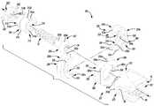
이제 도 21 내지 도 23을 참조하여, 일 실시예에서, 다중평면 뼈 앵커 시스템(500)은 연결 로드(20)와 함께 채택될 수 있어 해부 구조의 손상된 부분을 보수한다. 다중평면 뼈 앵커 시스템(500)은 도 9 내지 도 15를 참조하여 설명된 다중평면 뼈 앵커 시스템(100, 200)과 유사할 수 있기에, 다중평면 뼈 앵커 시스템(100, 200)과 다중평면 뼈 앵커 시스템(500) 사이의 차이만이 여기서 더 상세하게 논의될 것이고, 동일한 참조번호들은 동일하거나 유사한 구성요소들을 나타내는 데에 사용될 것이다. 다중평면 뼈 앵커 시스템(500)은 뼈 패스너(102), 잠금 링(502), 다중평면 연결 장치 또는 시스템(504) 및 새들(506)을 포함할 수 있다. 비록 다중평면 뼈 앵커 시스템(500)은 잠금 링(502)을 포함하는 것으로서 여기서 설명되고 도시되더라도, 다중평면 뼈 앵커 시스템(500)은 잠금 링(502)을 포함할 필요가 없다는 것이 이해되어야 하는 것이 언급되어야 한다. 더욱이, 요구된다면, 다중평면 뼈 앵커 시스템(500)은 잠금 링(502) 대신에 잠금 링(14)을 채택할 수 있다.Referring now to FIGS. 21-23, in one embodiment, the multiplanar
잠금 링(502)은 새들(506) 내에 수용될 수 있고, 요구된 각도 위치로 뼈 패스너(102)를 고정되게 연결시키거나 고정시키도록 새들(506) 및 다중평면 연결 시스템(504)을 상호작용시킬 수 있다(도 23). 일 실시예에서, 도 22를 참조하여, 잠금 링(502)은 연속적인 실린더형 몸체를 포함할 수 있고, 어떠한 적절한 생체에 적합한 재료, 예를 들어 생체에 적합한 금속, 세라믹, 금속 합금, 폴리머 또는 이의 조합들로부터 형성될 수 있다. 잠금 링(502)은 제 1 종단 또는 근위단(507), 제 2 종단 또는 원위단(508), 및 플랜지(509)를 포함할 수 있다. 게다가, 잠금 링(502)은 보어(502a)를 포함할 수 있고, 이는 도구가 뼈 패스너(102)의 드라이버 인터페이스 구조체(34)에 맞물리는 것을 가능하게 할 수 있다.The
잠금 링(502)의 근위단(507)은 제 1 오목 표면(507a)을 한정할 수 있고, 이는 연결 로드(20)와 대응하도록 구성된 곡률을 가질 수 있다. 이런 점에서, 연결 로드(20)가 다중평면 뼈 앵커 시스템(500)에 연결될 때 잠금 링(502)은 연결 로드(20)의 일부를 지지할 수 있다. 본 실시예에서, 다중평면 뼈 앵커 시스템(500)에 연결 로드(20)를 연결시키도록 멈춤 나사(22)에 의해 적용된 힘은 요구된 각도 위치에서 뼈 패스너(102)를 고정되게 연결시키거나 고정시키도록 잠금 링(502)에 힘을 적용시킬 수 있다.The
잠금 링(502)의 원위단(508)은 요구된 각도 위치에서 뼈 패스너(102)를 고정되게 연결시키거나 고정시키도록 뼈 패스너(102)의 헤드(108)에 힘을 적용시킬 수 있다. 도 23을 참조하여, 원위단(508)은 제 2 오목 표면(508a)을 한정할 수 있다. 힘이 잠금 링(502)에 적용될 때 오목 표면(508a)은 뼈 패스너(102)의 헤드(108)와 맞물려 요구된 각도 위치에서 뼈 패스너(102)를 고정되게 연결시키거나 고정시키도록 구성될 수 있다.The
플랜지(509)는 잠금 링(502)의 원주 주위에서 연장될 수 있고, 잠금 링(502)의 원위단(508)과 근위단(507) 사이에 위치될 수 있다. 플랜지(509)는 잠금 링(502)과 함께 일체형으로 형성될 수 있거나, 또는 어떠한 적절한 제조 기술, 예를 들어 오버몰딩(overmolding), 접착제 등을 통해 잠금 링(502)의 원주에 연결될 수 있다. 여기서 더 상세하게 논의될 것인 바와 같이, 플랜지(509)는 다중평면 연결 시스템(504)의 일부에 맞물려 다중평면 연결 시스템(504)에 잠금 링(502)을 연결시키도록 구성될 수 있다.The
도 21 내지 도 23을 참조하여, 다중평면 연결 시스템(504)은 연결 아암(510), 적어도 하나의 플러그(538) 및 유지 클립(retaining clip)(538)을 포함할 수 있다. 일 실시예에서, 다중평면 연결 시스템(504)은 2개의 플러그(538)들을 포함할 수 있다. 연결 아암(510) 및 플러그(538)들은 뼈 패스너(102)가 새들(506)에 대하여 이동하는 것을 가능하게 하도록 뼈 패스너(102)와 상호작용할 수 있다. 연결 아암(510)은 뼈 패스너(102)가 새들(206)에 대하여 이동하거나 관절로 이어지는 것을 가능하게 하도록 뼈 패스너(102)의 헤드(30) 주위에 위치될 수 있다. 본 실시예에서, 논의될 것인 바와 같이, 연결 아암(510)은 실린더형일 수 있고, 유지 클립(514)을 통해 새들(506)에 연결될 수 있다(도 23). 연결 아암(510)은 제 1 종단 또는 근위단(520), 채널(522), 제 2 종단 또는 원위단(524) 및 보어(526)를 포함할 수 있다.With reference to FIGS. 21-23, the
새들(206)이 연결 아암(510)에 연결될 때 근위단(520)은 새들(506) 내에 수용될 수 있다(도 23). 채널(522)은 근위단(520)과 원위단(524) 사이에 위치될 수 있다. 논의될 것인 바와 같이, 채널(522)은 새들(506) 내에 수용될 수 있고, 새들(506)에 연결 아암(510)을 연결시키도록 새들(506) 및 유지 클립(514)과 상호 작용할 수 있다. 연결 아암(510)이 새들(506)에 연결될 때 다수의 원위단(524)은 새들(506)의 외부에 위치될 수 있다(도 23). 원위단(524)은 적어도 하나의 플랜지(528)를 포함할 수 있다.The
일 실시예에서, 도 23을 지속적으로 참조하여, 원위단(524)은 2개의 플랜지들(528a, 528b)을 포함할 수 있다. 일반적으로, 도 22에 도시된 바와 같이, 플랜지(528)들은 상호 간에 반대에 위치될 수 있고, 연결 아암(510)의 원위단(524)을 넘는 길이를 위해 각각 연장될 수 있다. 도 23을 다시 참조하여, 플랜지(528)들의 각각은 보어(530)를 포함할 수 있다. 여기서 더 상세하게 논의될 것인 바와 같이, 보어(530)들의 각각은 연결 아암(510)에 뼈 패스너(102)를 연결시키도록 플러그(538)들 중 하나의 일부를 수용할 수 있다. 일 실시예에서, 보어(530)들은 보어(530)들은 보어(526)에 연결되도록 플랜지(528)들의 원주를 통해 한정될 수 있다.In one embodiment, continuing with reference to FIG. 23, the
보어(526)는 근위단(520)으로부터 원위단(524)까지 한정될 수 있다. 보어(526)는 연결 아암(510)의 중심축 주위에 형성될 수 있다. 다중평면 뼈 앵커 시스템(500)이 조립될 때 보어(526)는 잠금 링(502)의 적어도 일부를 수용할 수 있다. 이런 점에서, 도 23을 참조하여, 보어(526)는 잠금 링 연결부(526a), 베어링부(526b) 및 제한부(limiting portion)(526c)를 포함할 수 있다.
잠금 링 연결부(526a)는 근위단(520)에 또는 그 근처에 형성될 수 있다. 잠금 링 연결부(526a)는 잠금 링(502)의 플랜지(509)에 맞물려 연결 아암(510)에 잠금 링(502)을 연결시키도록 구성될 수 있다. 일 실시예에서, 잠금 링 연결부(526a)는 잠금 링(502)의 외부 윤곽과 대응하는 윤곽을 갖는 보어(526)의 일부를 포함할 수 있지만, 잠금 링 연결부(526a)는 연결 아암(510) 내에 잠금 링(502)을 유지하도록 작동되는 어떠한 요구된 구성을 가질 수 있다는 것이 이해되어야 한다. 본 실시예에서, 잠금 링 연결부(526a)는 잠금 링(502)의 근위단(507)이 연결 아암(510)의 근위단(520)을 넘어 연장되도록 형성될 수 있어서, 연결 로드(20)는 잠금 링(502)의 오목 표면(507a) 내에 수용될 수 있다.
베어링부(526b)는 연결 아암(510)의 근위단(520)에 인접하게 형성될 수 있다. 베어링부(526b)는 일반적으로 오목일 수 있고, 뼈 패스너(102)의 반구형 헤드(30)의 적어도 일부와 대응하도록 구성될 수 있다. 베어링부(526b)는 뼈 패스너(102)가 연결 아암(510)에 대하여 이동하는 것, 회전하는 것, 또는 관절로 이어지는 것을 가능하게 할 수 있다. 제한부(526c)는 연결 아암(510)의 원위단(524)에 인접하게 한정될 수 있다. 비록 여기서 도시되지 않더라도, 요구된다면, 제한부(526c)는 테이퍼를 포함할 수 있다. 일반적으로, 제한부(526c)는 뼈 패스너(102)의 이동 또는 관절의 범위를 제한할 수 있다.The bearing
도 22를 참조하여, 플러그(538)들은 뼈 패스너(102)가 뼈 패스너(102)의 길이방향 축(L2)을 중심으로 이동하거나 회전하는 것을 가능하게 하도록 연결 아암(510)과 상호작용할 수 있다. 플러그(538)들은 연결 아암(510)에 뼈 패스너(102)를 연결시킬 수 있다. 플러그(538)들의 각각은 연결단(coupling end)(540)을 포함할 수 있다. 연결단(540)은 연결 아암(510)에 플러그(538)를 연결시킬 수 있다. 연결단(540)은 조임 구조체(540a)를 포함할 수 있고, 이는 플러그(538)들이 연결 아암(510)에 연결될 때 접근가능할 수 있다. 조임 구조체(540a)는 어떠한 적절한 구조체, 예를 들어, 슬롯, 컷-아웃부 또는 도구에 의해 맞물릴 수 있는 다른 구조체를 포함할 수 있다. 일반적으로, 조임 구조체(540a)는 도구, 예를 들어 드라이버가 뼈 패스너(12)의 헤드(30) 및 연결 아암(510)에 플러그(538)를 연결시키는 것을 가능하게 할 수 있다. 게다가, 요구된다면, 플러그(538)들은 연결 아암(510)과 일체형으로 형성될 수 있다. 플러그(538)들이 어떠한 요구된 형상, 예를 들어 타원형, 구형, 둥근형, 환형, 실린더형, 둥근 사각형, 둥근 직사각형 등을 가질 수 있기에, 플러그(538)들의 형상은 단지 예시적이다는 것이 언급되어야 한다. 게다가, 비록 여기서 도시되지 않더라도, 플러그(538)들은 하나 이상의 테이퍼진 표면을 포함할 수 있고, 이는 요구된다면, 뼈 패스너(102)가 연결 아암(510)에 대하여 이동하거나 선회하는 것을 가능하게 할 수 있다.Referring to FIG. 22, the
도 22와 도 23을 참조하여, 유지 클립(514)은 연결 아암(510)에 새들(506)을 연결시킬 수 있다. 예를 들어, 유지 클립(514)은 실질적으로 U자 형상 클립, 예를 들어 더치맨 클립(Dutchman clip)을 포함할 수 있다. 더치맨 클립이 일반적으로 공지되기에, 유지 클립(514)은 여기서 더 상세하게 논의되지 않을 것이다. 하지만, 간략하게, 유지 클립(514)은 제 1 아암(514a) 및 제 2 아암(514b)을 한정할 수 있고, 이는 커넥터(514c)를 통해 함께 연결될 수 있다. 제 1 아암(514a) 및 제 2 아암(514b)의 각각은 잠금 탱(locking tang)(T)을 포함할 수 있다. 일반적으로, 제 1 아암(514a) 및 제 2 아암(514b)은 유연할 수 있어서, 유지 클립(514)은 연결 아암(510) 및 새들(506)과의 맞물림으로 바이어싱될(biased) 수 있다. 논의될 것인 바와 같이, 유지 클립(514)은 연결 아암(510)에 새들(506)을 이동가능하거나 회전가능하게 연결시키도록 연결 아암(510)의 채널(522) 또는 새들(506)의 일부를 통해 수용될 수 있다.With reference to FIGS. 22 and 23, retaining
새들(506)은 제 1 종단 또는 근위단(76) 및 제 2 종단 또는 원위단(550)을 포함할 수 있다. 원위단(550)은 일반적으로 실린더형일 수 있고, 제 1 표면 또는 리시버 표면(88), 제 2 표면 또는 바닥 표면(552), 중심 보어(554) 및 적어도 하나의 슬롯(556)을 포함할 수 있다.The
도 23에서 최상으로 도시된 바와 같이, 바닥 표면(552)은 테이퍼(552a)를 포함할 수 있다. 테이퍼(552a)는 비외상 엣지들을 갖는 바닥 표면(552)을 제공할 수 있다. 중심 보어(554)는 리시버 표면(88)으로부터 새들(506)의 바닥 표면(552)을 통해 한정될 수 있다. 중심 보어(554)는 그 안에서 회전가능하게 연결 아암(510)의 적어도 일부를 수용하도록 구성될 수 있다. 따라서, 중심 보어(554)는 연결 아암(510)의 직경보다 약간 클 수 있는 직경을 가질 수 있어서, 연결 아암(510)은 새들(506)에 대해 회전할 수 있다.As best shown in FIG. 23, the
적어도 하나의 슬롯(556)은 새들(506)의 원위단(550)의 일부를 통해 한정될 수 있다. 일 실시예에서, 적어도 하나의 슬롯(556)은 2개의 슬롯(556)들을 포함할 수 있다. 2개의 슬롯(556)들은 상호 간에 반대편에 형성될 수 있고, 일반적으로 유지 클립(514)의 커넥터(514c)의 길이에 거의 동일한 2개의 슬롯(556)들 사이의 거리로 이격되어 형성될 수 있다.At least one
슬롯(556)들은 새들(506)의 원위단(550)의 제 1 측(550a)으로부터 제 2 측(550b)까지 한정될 수 있다. 슬롯(556)들은 제 1 측(550a)으로부터 제 2 측(550b)까지의 길이를 가질 수 있고, 이는 제 1 아암(514a) 및 제 2 아암(514b)의 길이에 거의 동일할 수 있다. 슬롯(556)들의 길이를 부여한다면, 유지 클립(514)의 커넥터(514c)는 일반적으로 새들(506)의 원위단(550)의 외부 표면에 인접하게 위치될 수 있다(도 23). 하지만, 새들(506)은 유지 클립(514)이 연결 아암(510) 및 새들(506)에 연결될 때 커넥터(514c)가 새들(506) 내에 수용되도록 구성될 수 있다.
슬롯(556)들은 각각 탭(556a)을 포함할 수 있고, 이는 원위단(550)의 제 2 측(550b) 근처에 형성될 수 있다. 탭(556a)은 새들(506)에 유지 클립(514)을 연결시키도록 제 2 아암(514b) 및 제 1 아암(514a)의 탱(T)과 상호작용할 수 있다. 새들(506)에 유지 클립(514)을 연결시킴으로써, 연결 아암(510)은 또한 새들(506)에 연결될 수 있다.
이런 점에서, 도 22와 도 23을 참조하여, 다중평면 뼈 앵커 시스템(500)을 조립하기 위하여, 잠금 링(502)은 보어(526) 내에 위치될 수 있고 잠금 링(502)의 플랜지(509)를 통해 잠금 링 연결부(526a)에 연결될 수 있다. 연결 아암(510)에 연결된 잠금 링(502)으로, 새들(506)의 원위단(550)은 연결 아암(510)의 원위단(520) 상으로 위치될 수 있다. 다음으로, 뼈 패스너(102)는 뼈 패스너(102)가 연결 아암(510)에 대하여 이동할(회전할 및 선회할) 수 있도록 연결 아암(510)의 보어(530)들과의 맞물림 안으로 플러그(538)들을 스냅-끼워 맞춰지거나, 프레스-끼워 맞춰지거나, 쓰레딩함으로써 연결 아암(510)에 연결될 수 있다.In this regard, with reference to FIGS. 22 and 23, in order to assemble the multiplanar
적어도 연결 아암(510)의 근위단(520) 주위에 위치된 새들(506)의 원위단(550)으로, 유지 클립(514)은 제 2 아암(541b) 및 제 1 아암(541a)의 탱(T)들이 슬롯(556)들의 탭(556a)들에 맞물릴 수 있도록 슬롯(556)들 안으로 삽입될 수 있다. 제 1 아암(514a) 및 제 2 아암(514b)은 제 1 아암(514a) 및 제 2 아암(514b)이 연결 아암(510)의 채널(522) 내에 적어도 부분적으로 유지될 수 있도록 삽입될 수 있다. 따라서, 유지 클립(514)은 새들(506)에 뼈 패스너(102) 및 연결 아암(510)을 연결시키도록 채택될 수 있다.At least with the
일단 조립된다면, 플러그(538)들은 뼈 패스너(102)의 중심축 또는 길이방향 축을 중심으로 뼈 패스너(102)의 이동 또는 회전을 가능하게 하도록 뼈 패스너(102)의 채널(108)과 상호작용할 수 있고, 이에 의해 제 1 운동 평면을 제공한다. 게다가, 유지 클립(514)은 연결 아암(510)이 새들(506)에 대하여 이동하거나 회전하는 것을 가능하게 할 수 있고, 이에 의해 제 2 운동 평면을 한정한다. 따라서, 조립될 때, 다중평면 뼈 앵커 시스템(500)은 적어도 2개의 운동 평면들 또는 2도의 운동을 가질 수 있다. 다중평면 뼈 앵커 시스템(500)이 적어도 2개의 평면들에서 이동하도록 함으로써, 외과의사는 환자의 해부 구조에 일치시키는 데 필요하기에 다중평면 뼈 앵커 시스템(500)을 조작할 수 있다.Once assembled, the
고정 절차에서 다중평면 뼈 앵커 시스템(500)의 사용 및 수술 삽입이 고정 절차에서 다중평면 뼈 앵커 시스템(100, 200)의 삽입 및 수술 삽입과 유사할 수 있기에, 다중평면 뼈 앵커 시스템(500)의 사용 및 수술 삽입은 여기서 더 상세하게 논의되지 않을 것이다. 하지만, 간략하게, 일단 다중평면 뼈 앵커 시스템(500)이 해부 구조에 고정된다면, 다중평면 뼈 앵커 시스템(500)이 고정 절차를 위한 요구된 정렬에 존재할 때까지 뼈 패스너(102), 다중평면 연결 시스템(504) 및/또는 새들(506)은 상호 간에 대하여 이동될 수 있거나, 또는 회전될 수 있다. 일단 정렬된다면, 연결 로드(20)는 요구된 개수의 다중평면 뼈 앵커 시스템(500)들에 연결될 수 있다.Since the use and surgical insertion of the multiplanar
이제 도 24 내지 도 26을 참조하여, 일 실시예에서, 다중평면 뼈 앵커 시스템(600)은 연결 로드(20)와 함께 채택될 수 있어 해부 구조의 손상된 부분을 보수한다. 다중평면 뼈 앵커 시스템(600)은 도 18 내지 도 20을 참조하여 설명된 다중평면 뼈 앵커 시스템(400)과 유사할 수 있기에, 다중평면 뼈 앵커 시스템(400)과 다중평면 뼈 앵커 시스템(600) 사이의 차이만이 여기서 더 상세하게 논의될 것이고, 동일한 참조번호들은 동일하거나 유사한 구성요소들을 나타내는 데에 사용될 것이다. 다중평면 뼈 앵커 시스템(600)은 뼈 패스너(102), 잠금 링(602), 다중평면 연결 장치 또는 시스템(604) 및 새들(606)을 포함할 수 있다.Referring now to FIGS. 24-26, in one embodiment, the multiplanar
잠금 링(602)은 뼈 패스너(102)의 헤드(108) 주위에 위치될 수 있다. 여기서 논의될 것인 바와 같이, 잠금 링(602)은 연결 로드(20)에 의해 적용된 힘을 통해 다중평면 연결 시스템(604)에 대하여 뼈 패스너(102)를 연결시킬 수 있거나 고정시킬 수 있다. 도 26을 참조하여, 잠금 링(602)은 일반적으로 실린더형일 수 있고, 높이(H6)를 가질 수 있다. 새들(606)에 연결 로드(20)를 연결시키는 것은 뼈 패스너(102)의 헤드(108) 상으로 잠금 링(602)을 압축시킬 수 있도록 높이(H6)는 새들(606)의 리시버 표면(88)을 넘거나 거의 동일하게 연장되는 크기가 될 수 있다. 본 실시예에서, 잠금 링(602)은 컷 아웃부(602a)를 포함할 수 있고, 이는 뼈 패스너(102)의 헤드(108) 주위에 잠금 링(602)을 위치시키는 것을 용이하게 할 수 있다. 하지만, 잠금 링(602)이 연속적이고 중단되지 않는 실린더형 몸체를 가질 수 있기에, 컷 아웃부(602a)가 선택적일 수 있다는 것이 이해되어야 한다. 게다가, 잠금 링(602)은 근위단(408), 원위단(610), 플랜지(412) 및 보어(414)를 포함할 수 있다. 도 25와 도 26을 참조하여, 잠금 링(602)이 뼈 패스너(102)에 연결될 때 원위단(610)은 뼈 패스너(102)의 헤드(108)에 연결될 수 있다.The
다중평면 연결 시스템(604)은 연결 아암(620)을 포함할 수 있다. 연결 아암(620)은 뼈 패스너(102)가 새들(606)에 대하여 이동하는 것을 가능하게 하도록 뼈 패스너(102)와 상호작용할 수 있다. 비록 다중평면 연결 시스템(604)이 연결 아암(620)만을 포함하는 것으로서 여기서 설명되고 도시되더라도, 요구된다면, 다중평면 연결 시스템(604)은 링, 예를 들어 도 16에 도시된 링(32)을 포함할 수 있다는 것이 언급되어야 한다. 본 실시예에서 연결 아암(620)은 실린더형 몸체를 가질 수 있고, 이는 컷 아웃부(620a)를 포함할 수 있다. 컷 아웃부(620a)는 뼈 패스너(102)의 헤드(108)에 연결 아암(620)의 연결을 용이하게 할 수 있다. 예를 들어, 컷 아웃부(620a)는 연결 아암(620)이 뼈 패스너(102)의 헤드(108) 주위에 스냅-끼워맞춰지는 것을 가능하게 할 수 있다. 하지만, 연결 아암(620)이 연속적이고 중단되지 않는 실린더형 몸체를 가질 수 있기에, 컷 아웃부(620a)가 선택적일 수 있다는 것이 언급되어야 한다. 연속적이고, 중단되지 않는 실린더형 몸체의 경우에, 연결 아암(620)은 뼈 패스너(102)의 헤드(108)와 맞물림 안으로 뼈 패스너(102)의 섕크(32)에 걸쳐 쓰레딩될 수 있다.
본 실시예에서, 연결 아암(620)은 제 1 종단 또는 근위단(622), 제 2 종단 또는 원위단(424), 채널(426), 보어(428) 및 도구 구조체(430)를 더 포함할 수 있다. 근위단(622)은 복수 개의 아치형 부재(622a)들을 포함할 수 있고, 이는 각각 하나 이상의 공간(622b)에 의해 분리될 수 있다. 복수 개의 아치형 부재(622a)들은 일반적으로 근위단(622)의 원주 주위에 형성될 수 있다. 복수 개의 아치형 부재(622a)들은 새들(606)에 연결 아암(620)을 연결시키도록 채널(426)과 상호작용할 수 있다. 하나 이상의 공간(622b)은 복수 개의 아치형 부재(620a)들이 유연하게 되는 것을 가능하게 할 수 있어서, 복수 개의 아치형 부재(620a)들이 새들(606)과의 맞물림 안으로 스냅-끼워 맞춰질 수 있다.In this embodiment, the connecting
일반적으로, 도 25와 도 26을 참조하여, 새들(606)은 연결 아암(620)이 새들(606)에 대하여 이동할 수 있거나 회전할 수 있도록 연결 아암(620)에 연결될 수 있다. 새들(606)은 실질적으로 U자 형상일 수 있고, 다중평면 뼈 앵커 시스템(600)에 의해 한정된 길이방향 축(L2)에 대해 대칭일 수 있다. 새들(606)은 제 1 종단 또는 근위단(76) 및 제 2 종단 또는 원위단(640)을 포함할 수 있다.25 and 26, the
도 25를 참조하여, 새들(606)의 원위단(640)은 일반적으로 직사각형일 수 있고, 제 1 표면 또는 리시버 표면(88), 제 2 표면 또는 바닥 표면(644) 및 보어(646)를 포함할 수 있다. 도 26을 참조하여, 바닥 표면(644)은 립(644a)을 포함할 수 있다. 립(644a)은 바닥 표면(644)의 둘레 주위에서 바닥 표면(644)으로부터 하측으로 연장될 수 있다. 립(644a)은 채널(426) 안에 수용되도록 구성될 수 있어서, 보어(464)의 일부는 연결 아암(620)에 새들(606)을 연결시키도록 복수 개의 아치형 부재(620a)들을 둘러쌀 수 있다. 이는 또한 새들(606)이 연결 아암(620)에 대하여 이동하거나 회전하는 것을 가능하게 할 수 있다.Referring to FIG. 25, the
도 25와 도 26을 참조하여, 다중평면 뼈 앵커 시스템(600)을 조립하기 위하여, 연결 아암(620)은 뼈 패스너(102)의 채널(108)에 연결될 수 있다. 이어서, 잠금 링(602)은 연결 아암(620)에 연결될 수 있다. 다음으로, 새들(606)의 원위단(640)은 연결 아암(620)이 새들(606)에 대하여 이동할 수 있거나 회전할 수 있도록 연결 아암(620)에 연결될 수 있다.25 and 26, to assemble the multiplanar
일단 조립된다면, 연결 아암(620)은 뼈 패스너(102)의 중심축 또는 길이방향 축을 중심으로 뼈 패스너(102)의 이동 또는 회전을 가능하게 하도록 뼈 패스너(102)와 상호작용할 수 있고, 이는 제 1 운동 평면을 제공할 수 있다. 새들(606)은 또한 연결 아암(620)에 대하여 회전할 수 있고, 이는 이에 의해 제 2 운동 평면을 한정한다. 게다가, 새들(606)은 뼈 패스너(102)에 대하여 회전할 수 있어 이에 의해 제 3 운동 평면을 한정한다. 따라서, 조립될 때, 다중평면 뼈 앵커 시스템(600)은 적어도 3도의 운동 또는 3개의 운동 평면들을 가질 수 있다. 다중평면 뼈 앵커 시스템(600)이 적어도 3개의 평면들에서 이동하도록 함으로써, 외과의사는 환자의 해부 구조에 일치시키는 데 필요하기에 다중평면 뼈 앵커 시스템(600)을 조작할 수 있다.Once assembled, the connecting
고정 절차에서 다중평면 뼈 앵커 시스템(600)의 사용 및 수술 삽입이 고정 절차에서 다중평면 뼈 앵커 시스템(400)의 삽입 및 수술 삽입과 유사할 수 있기에, 다중평면 뼈 앵커 시스템(600)의 사용 및 수술 삽입은 여기서 더 상세하게 논의되지 않을 것이다. 하지만, 간략하게, 일단 다중평면 뼈 앵커 시스템(600)이 해부 구조에 고정된다면, 다중평면 연결 시스템(604) 및 새들(606)은 고정 절차를 위한 요구된 정렬로 뼈 패스너(102)에 대하여 이동될 수 있거나 회전될 수 있다. 일단 정렬된다면, 연결 로드(20)는 요구된 개수의 다중평면 뼈 앵커 시스템(600)들에 연결될 수 있다.The use of the multiplane
따라서, 다중평면 뼈 앵커 시스템(10, 100, 200, 300, 400, 500, 600)은 척추 고정 또는 융합 절차의 경우에서와 같이 해부 구조에서 손상된 조직을 보수하는 데에 사용될 수 있다. 뼈 패스너(12, 102, 302) 및/또는 새들(18, 106, 206, 308, 406, 506, 606)이 다중 평면들에서 이동하도록 함으로써, 제어된 방식으로 존재한다. 게다가, 뼈 패스너(12, 102, 302) 및/또는 새들(18, 106, 206, 308, 406, 506, 606)의 위치를 조작하는 능력은 다중평면 뼈 앵커 시스템(10, 100, 200, 300, 400, 500, 600)이 다양하고 상이한 해부상 구조물과 함께 사용되는 것을 가능하게 할 수 있다.Thus, the multiplanar
특정한 실시예들이 명세서에서 설명되고 도면들에서 도시된 반면에, 다양한 변화가 이루어질 수 있고, 등가물이 본 발명의 범위로부터 벗어남이 없이 이의 요소들로 대체될 수 있다는 것이 기술분야의 통상의 지식을 가진 자에 의해 이해될 것이다. 더욱이, 다양한 실시예들 사이에서 구조체들, 요소들 및/또는 기능들의 혼합 및 대응은 여기서 분명히 고려되어서 기술 분야의 통상의 지식을 가진 자는 일 실시예의 구조체들, 요소들 및/또는 기능들이 상기에 달리 설명되지 아니한 경우 이외에, 적절하게 다른 실시예로 포함될 수 있다는 것을 본 발명으로부터 인식할 것이다. 더욱이, 많은 변경이 이의 본질적인 범위로부터 벗어남이 없이 본 발명에 대한 특정한 상황 또는 재료를 맞추도록 이루어질 수 있다. 따라서, 본 발명은 명세서에서 설명되고 도면들에 의해 도시된 특정한 실시예들로 한정되지 않으나, 본 발명의 범위는 앞선 말한 설명 내에서 빠지는 어떠한 구체예들을 포함할 것이다는 것이 의도된다.While specific embodiments have been described in the specification and are shown in the drawings, it is understood by those skilled in the art that various changes may be made and equivalents may be substituted with elements thereof without departing from the scope of the present invention. It will be understood by one. Furthermore, it should be apparent to those skilled in the art that the mixture and correspondence of structures, elements, and / or functions among various embodiments is contemplated herein, and those skilled in the art will appreciate that the structures, elements and / It will be appreciated from the present invention that other embodiments may be suitably included, other than when not otherwise described. Moreover, many modifications may be made to adapt a particular situation or material to the invention without departing from its essential scope. Thus, it is intended that the invention not be limited to the particular embodiments described in the specification and illustrated by the drawings, but that the scope of the invention will include any embodiments falling within the foregoing description.
예를 들어, 다중평면 뼈 앵커 시스템(300)이 뼈 패스너(302), 잠금 링(304), 연결 아암(320), 링(322) 및 바닥부(350)를 포함하는 것으로서 도 15 내지 도 17을 참조하여 여기서 설명되어 온 반면에, 기술분야에서 통상의 지식을 가진 자는 가장 넓은 양상에서, 본 개시가 다소 간에 상이하게 구성될 수 있다는 것을 인지할 것이다. 이런 점에서, 다중평면 뼈 앵커 시스템(300')은 도 27에 도시된 바와 같이, 다중평면 뼈 앵커 시스템(400)과 연관된 뼈 패스너(102), 잠금 링(402), 연결 아암(420) 및 바닥부(460)를 포함할 수 있다. 본 실시예에서, 다중평면 뼈 앵커 시스템(300')은 운동의 다중 평면들을 제공할 수 있는 동시에, 더 적은 구성요소들을 요구하고, 이는 제조 목적을 위해 바람직할 수 있다.For example, the multiplanar
추가적인 실시예로서, 다중평면 뼈 앵커 시스템(10, 100, 200, 500)은 링(50, 112, 512)을 갖는 것으로써 여기서 설명되어 온 반면에, 기술분야에서 통상의 지식을 가진 자는 가장 넓은 양상에서, 본 개시가 다소 간에 상이하게 구성될 수 있다는 것을 인지할 것이다. 이런 점에서, 도 28 내지 도 30을 참조하여, 연결 아암(700)은 링(50, 112, 512)을 대신하여 채택될 수 있다. 연결 아암(700)은 뼈 패스너(102)와 상호작용할 수 있고, 적어도 하나의 보어(702) 및 적어도 하나의 플러그(704)를 포함할 수 있다. 연결 아암(700)은 또한 관통 보어(706)를 포함할 수 있고, 이는 그 안에 뼈 패스너(102)의 헤드(108)를 수용할 수 있다. 적어도 하나의 플러그(704)는 연결 아암(700)의 적어도 하나의 보어(702)에 연결될 수 있어 뼈 패스너(102)가 연결 아암(700)에 대하여 회전하는 것을 가능하게 한다. 본 실시예에서, 적어도 하나의 플러그(704)는 2개의 플러그(704)들을 포함하고, 이는 2개의 반대 보어(702)들 내에 수용될 수 있다. 플러그(704)들의 각각은 플러그(704)들 상에 형성된 베어링 표면(704a)이 뼈 패스너(102)의 채널(108a)을 중심으로 회전할 수 있도록 보어(702)들 안으로 프레스 끼워맞춰질 수 있다.As a further embodiment, the multiplanar
Claims (20)
Translated fromKorean해부 구조에 맞물리도록 맞춰진 제 2 종단 및 헤드를 포함하고, 길이방향 축을 따라 연장되는 뼈 패스너;
제 1 운동 평면을 한정하기 위하여 뼈 패스너가 길이방향 축을 중심으로 회전가능하고 선회가능하도록 뼈 패스너의 헤드에 연결되는 연결 장치; 및
연결 장치에 연결되고, 제 2 운동 평면을 한정하기 위하여 연결 장치 및 뼈 패스너 중 적어도 하나에 대하여 이동가능한 새들(saddle)을 포함하는 것을 특징으로 하는 시스템.
In a multiplane bone anchor system for fixation procedures,
A bone fastener comprising a second end and a head adapted to engage the anatomy and extending along a longitudinal axis;
A connecting device connected to the head of the bone fastener such that the bone fastener is rotatable and pivotable about the longitudinal axis to define a first plane of motion; And
A saddle connected to the coupling device and movable relative to at least one of the coupling device and the bone fastener to define the second plane of motion.
연결 장치에 연결되는 제 1 부분; 및
제 1 부분에 연결되고, 제 3 운동 평면을 한정하기 위하여 제 1 부분에 대하여 이동가능한 제 2 부분을 더 포함하는 것을 특징으로 하는 시스템.
The method of claim 1 wherein the birds,
A first portion connected to the connecting device; And
And a second portion connected to the first portion and movable relative to the first portion to define a third plane of motion.
제 2 부분은 유지 클립, 유지 링, 열장이음 연결부 또는 이의 조합들에 의해 제 1 부분에 연결되는 것을 특징으로 하는 시스템.
The method of claim 2,
And the second portion is connected to the first portion by a retaining clip, retaining ring, dovetail connection, or combinations thereof.
새들은 적어도 하나의 레일을 포함하고 연결 장치는 적어도 하나의 가이드를 포함하며, 제 2 운동 평면을 한정하기 위하여 상기 적어도 하나의 레일은 상기 적어도 하나의 가이드에 슬라이딩가능하게 연결되는 것을 특징으로 하는 시스템.
The method of claim 1,
The saddle comprises at least one rail and the connecting device comprises at least one guide, wherein the at least one rail is slidably connected to the at least one guide to define a second plane of motion. .
새들 및 연결 장치 중 적어도 하나 및 뼈 패스너의 헤드에 연결되고, 새들에 대하여 뼈 패스너의 위치를 고정하는 힘을 수용하도록 구성되는 잠금 링을 더 포함하는 것을 특징으로 하는 시스템.
The system of claim 1, wherein the system is
And a locking ring connected to at least one of the saddle and the connecting device and to the head of the bone fastener, the locking ring being configured to receive a force for securing the position of the bone fastener relative to the saddle.
뼈 패스너는 척추경 나사(pedicle screw)를 포함하는 것을 특징으로 하는 시스템.
The method of claim 1,
The bone fasteners comprise a pedicle screw.
뼈 패스너의 헤드는 채널을 한정하고,
연결 장치는 채널에 맞물려 뼈 패스너에 연결 아암을 회전가능하게 연결시키도록 작동하는 연결부를 한정하는 연결 아암을 더 포함하는 것을 특징으로 하는 시스템.
The method of claim 1,
The head of the bone fastener defines the channel,
The connecting device further comprises a connecting arm defining a connecting portion operatively engaged with the channel to rotatably connect the connecting arm to the bone fastener.
연결 장치는 뼈 패스너의 헤드 주위에 연결된 링을 더 포함하되,
링은 새들에 링을 회전가능하게 연결시키도록 작동하는 적어도 하나의 윙을 갖는 것을 특징으로 하는 시스템.
The method of claim 1,
The connecting device further comprises a ring connected around the head of the bone fastener,
And the ring has at least one wing operative to rotatably connect the ring to the saddle.
베어링 표면을 한정하는 새들에 연결되는 연결 아암을 더 포함하되,
상기 적어도 하나의 윙은 베어링 표면과 상호작용하여 링이 새들에 대해 회전하는 것을 가능하게 하는 것을 특징으로 하는 시스템.
The method of claim 8, wherein the system,
Further comprising a connecting arm connected to the saddle defining the bearing surface,
Said at least one wing interacting with a bearing surface to allow the ring to rotate relative to the saddle.
해부 구조에 맞물리도록 맞춰진 제 2 종단 및 헤드를 포함하고, 길이방향 축을 따라 연장되는 뼈 패스너;
뼈 패스너의 헤드에 연결되는 연결 장치; 및
제 1 부분 및 제 2 부분을 포함하는 새들(제 1 부분은 제 1 축을 따라 제 2 부분에 대하여 이동가능하고, 제 1 축은 뼈 패스너의 길이방향 축을 횡단하며, 제 2 부분은 뼈 패스너가 뼈 패스너의 헤드 주위에서 새들에 대해 선회가능하도록 연결 장치에 연결된다)을 포함하는 것을 특징으로 하는 시스템.
In a multiplane bone anchor system for fixation procedures,
A bone fastener comprising a second end and a head adapted to engage the anatomy and extending along a longitudinal axis;
A connecting device connected to the head of the bone fastener; And
Saddles comprising a first portion and a second portion, the first portion being movable relative to the second portion along a first axis, the first axis traversing the longitudinal axis of the bone fastener, the second portion being a bone fastener Coupled to the connecting device so as to be pivotable about the saddle around the head of the system.
제 1 부분은 적어도 하나의 가이드를 포함하고 제 2 부분은 적어도 하나의 레일을 포함하며, 제 1 부분의 상기 적어도 하나의 가이드는 제 2 부분의 상기 적어도 하나의 레일에 슬라이딩가능하게 연결되어 제 1 부분이 제 2 부분에 대해 이동하는 것을 가능하게 하는 것을 특징으로 하는 시스템.
11. The method of claim 10,
The first portion comprises at least one guide and the second portion comprises at least one rail, the at least one guide of the first portion being slidably connected to the at least one rail of the second portion, And the portion makes it possible to move relative to the second portion.
새들은 적어도 하나의 레일 반대편에 적어도 하나의 가이드를 포함하는 제 3 부분을 더 포함하되,
제 1 부분의 상기 적어도 하나의 가이드는 제 1 부분이 제 3 부분에 대해 이동가능하도록 제 3 부분의 상기 적어도 하나의 레일에 슬라이딩가능하게 연결되고,
제 2 부분의 상기 적어도 하나의 레일은 제 3 부분이 제 2 부분에 대해 이동가능하도록 제 3 부분의 상기 적어도 하나의 가이드에 슬라이딩가능하게 연결되는 것을 특징으로 하는 시스템.
11. The method of claim 10,
The birds further comprise a third portion comprising at least one guide opposite the at least one rail,
The at least one guide of the first portion is slidably connected to the at least one rail of the third portion such that the first portion is movable relative to the third portion,
The at least one rail of the second portion is slidably connected to the at least one guide of the third portion such that the third portion is movable relative to the second portion.
연결 장치는 적어도 하나의 윙을 포함하는 링을 더 포함하되,
링은 뼈 패스너의 헤드의 적어도 일부의 주위에 연결되는 것을 특징으로 하는 시스템.
The method of claim 11,
The connecting device further comprises a ring comprising at least one wing,
The ring is connected around at least a portion of the head of the bone fastener.
제 2 부분의 연결 보어는 베어링 표면을 더 포함하되,
링의 상기 적어도 하나의 윙은 베어링 표면에 연결되어 뼈 패스너가 제 2 부분에 대하여 회전하는 것을 가능하게 하는 것을 특징으로 하는 시스템.
The method of claim 13,
The connecting bore of the second part further comprises a bearing surface,
The at least one wing of the ring is connected to the bearing surface to enable the bone fastener to rotate relative to the second portion.
연결 장치는 연결 아암을 더 포함하되,
링의 상기 적어도 하나의 윙은 링이 연결 아암과 함께 회전하도록 연결 아암에 링을 연결시키는 것을 특징으로 하는 시스템.
The method of claim 13,
The connecting device further comprises a connecting arm,
The at least one wing of the ring connects the ring to the connection arm such that the ring rotates with the connection arm.
상기 적어도 하나의 윙은 적어도 하나의 테이퍼를 포함하되,
상기 적어도 하나의 테이퍼는 베어링 표면과 상호작용하여 뼈 패스너가 뼈 패스너의 헤드에 대하여 선회하는 것을 가능하게 하는 것을 특징으로 하는 시스템.
15. The method of claim 14,
The at least one wing includes at least one taper,
The at least one taper interacts with the bearing surface to enable the bone fastener to pivot about the head of the bone fastener.
제 2 부분은 보어를 한정하고,
상기 시스템은,
뼈 패스너의 헤드에 연결되고 제 2 부분의 보어를 통해 적어도 부분적으로 연장되는 잠금 링을 더 포함하는 것을 특징으로 하는 시스템.
11. The method of claim 10,
The second part defines the bore,
The system comprises:
And a locking ring connected to the head of the bone fastener and extending at least partially through the bore of the second portion.
잠금 링의 적어도 일부는 제 1 부분과 상호작용하여 제 2 부분에 대하여 제 1 부분의 이동을 제한하는 것을 특징으로 하는 시스템.
The method of claim 17,
At least a portion of the locking ring interacts with the first portion to limit movement of the first portion relative to the second portion.
해부 구조에 맞물리도록 맞춰진 제 2 종단 및 헤드를 포함하고, 길이방향 축을 한정하는 뼈 패스너;
뼈 패스너의 헤드 주위에 연결되고, 적어도 하나의 윙을 포함하는 링;
뼈 패스너의 헤드에 연결되는 원위단을 갖는 잠금 링;
제 1 부분 및 제 2 부분을 포함하는 새들(새들의 제 1 부분은 제 2 부분에 대하여 이동가능하도록 새들의 제 2 부분에 연결되고, 새들의 제 2 부분은 잠금 링의 적어도 일부, 링 및 패스너의 헤드 주위에 연결된다)을 포함하되,
링의 상기 적어도 하나의 윙은 새들의 제 2 부분 및 잠금 링과 상호작용하여 뼈 패스너가 뼈 패스너의 헤드를 중심으로 선회하는 것을 가능하게 하고, 상기 적어도 하나의 윙은 제 2 부분과 상호작용하여 뼈 패스너가 길이방향 축을 중심으로 회전하는 것을 가능하게 하는 것을 특징으로 하는 시스템.
In a multiplane bone anchor system for fixation procedures,
A bone fastener comprising a second end and a head adapted to engage the anatomy, the bone fastener defining a longitudinal axis;
A ring connected around the head of the bone fastener and including at least one wing;
A locking ring having a distal end connected to the head of the bone fastener;
Birds comprising a first portion and a second portion, the first portion of the birds being connected to the second portion of the birds so as to be movable relative to the second portion, the second portion of the birds being at least part of the locking ring, the ring and the fastener Connected around the head of the
The at least one wing of the ring interacts with the second portion of the birds and the locking ring to enable the bone fastener to pivot about the head of the bone fastener, the at least one wing interacting with the second portion And the bone fastener enables rotation about a longitudinal axis.
잠금 링의 원위단은 링의 상기 적어도 하나의 윙과 상호작용하여 뼈 패스너가 뼈 패스너의 헤드를 중심으로 선회하는 것을 가능하게 하는 적어도 하나의 컷-아웃부를 포함하는 것을 특징으로 하는 시스템.The method of claim 19,
And the distal end of the locking ring includes at least one cut-out portion that interacts with the at least one wing of the ring to enable the bone fastener to pivot about the head of the bone fastener.
Applications Claiming Priority (3)
| Application Number | Priority Date | Filing Date | Title |
|---|---|---|---|
| US12/614,734 | 2009-11-09 | ||
| US12/614,734US8449578B2 (en) | 2009-11-09 | 2009-11-09 | Multiplanar bone anchor system |
| PCT/US2010/054453WO2011056707A2 (en) | 2009-11-09 | 2010-10-28 | Multiplanar bone anchor system |
Publications (2)
| Publication Number | Publication Date |
|---|---|
| KR20120098768Atrue KR20120098768A (en) | 2012-09-05 |
| KR101427223B1 KR101427223B1 (en) | 2014-08-06 |
Family
ID=43970695
Family Applications (1)
| Application Number | Title | Priority Date | Filing Date |
|---|---|---|---|
| KR1020127014822AExpired - Fee RelatedKR101427223B1 (en) | 2009-11-09 | 2010-10-28 | Multiplanar bone anchor system |
Country Status (6)
| Country | Link |
|---|---|
| US (1) | US8449578B2 (en) |
| EP (1) | EP2498695A4 (en) |
| JP (1) | JP5852577B2 (en) |
| KR (1) | KR101427223B1 (en) |
| CN (1) | CN102711636B (en) |
| WO (1) | WO2011056707A2 (en) |
Families Citing this family (58)
| Publication number | Priority date | Publication date | Assignee | Title |
|---|---|---|---|---|
| US8366753B2 (en) | 2003-06-18 | 2013-02-05 | Jackson Roger P | Polyaxial bone screw assembly with fixed retaining structure |
| US8444681B2 (en) | 2009-06-15 | 2013-05-21 | Roger P. Jackson | Polyaxial bone anchor with pop-on shank, friction fit retainer and winged insert |
| US7875065B2 (en) | 2004-11-23 | 2011-01-25 | Jackson Roger P | Polyaxial bone screw with multi-part shank retainer and pressure insert |
| US9980753B2 (en) | 2009-06-15 | 2018-05-29 | Roger P Jackson | pivotal anchor with snap-in-place insert having rotation blocking extensions |
| US8979904B2 (en) | 2007-05-01 | 2015-03-17 | Roger P Jackson | Connecting member with tensioned cord, low profile rigid sleeve and spacer with torsion control |
| AU2010260521C1 (en) | 2008-08-01 | 2013-08-01 | Roger P. Jackson | Longitudinal connecting member with sleeved tensioned cords |
| US8998959B2 (en)* | 2009-06-15 | 2015-04-07 | Roger P Jackson | Polyaxial bone anchors with pop-on shank, fully constrained friction fit retainer and lock and release insert |
| CN103826560A (en) | 2009-06-15 | 2014-05-28 | 罗杰.P.杰克逊 | Polyaxial Bone Anchor with Socket Stem and Winged Inserts with Friction Fit Compression Collars |
| US11464549B2 (en) | 2009-06-15 | 2022-10-11 | Roger P. Jackson | Pivotal bone anchor assembly with horizontal tool engagement grooves and insert with upright arms having flared outer portions |
| US11229457B2 (en) | 2009-06-15 | 2022-01-25 | Roger P. Jackson | Pivotal bone anchor assembly with insert tool deployment |
| EP2485654B1 (en) | 2009-10-05 | 2021-05-05 | Jackson P. Roger | Polyaxial bone anchor with non-pivotable retainer and pop-on shank, some with friction fit |
| US9044272B2 (en) | 2009-11-09 | 2015-06-02 | Ebi, Llc | Multiplanar bone anchor system |
| US12383311B2 (en) | 2010-05-14 | 2025-08-12 | Roger P. Jackson | Pivotal bone anchor assembly and method for use thereof |
| US9113960B2 (en)* | 2010-06-08 | 2015-08-25 | Globus Medical, Inc. | Conforming bone stabilization receiver |
| US10603083B1 (en) | 2010-07-09 | 2020-03-31 | Theken Spine, Llc | Apparatus and method for limiting a range of angular positions of a screw |
| US9084634B1 (en)* | 2010-07-09 | 2015-07-21 | Theken Spine, Llc | Uniplanar screw |
| US9232969B2 (en)* | 2010-10-29 | 2016-01-12 | Warsaw Orthopedic, Inc. | Directional control for a multi-axial screw assembly |
| AU2011324058A1 (en) | 2010-11-02 | 2013-06-20 | Roger P. Jackson | Polyaxial bone anchor with pop-on shank and pivotable retainer |
| DE102010060555A1 (en)* | 2010-11-15 | 2012-05-16 | Ulrich Gmbh & Co. Kg | pedicle screw |
| US9603630B2 (en)* | 2011-04-29 | 2017-03-28 | Warsaw Orthopedic, Inc. | Rotatable base multi-axial screw assembly |
| US9358047B2 (en)* | 2011-07-15 | 2016-06-07 | Globus Medical, Inc. | Orthopedic fixation devices and methods of installation thereof |
| US11103286B2 (en)* | 2011-07-15 | 2021-08-31 | Globus Medical, Inc. | Orthopedic fixation devices and methods of installation thereof |
| EP2559389B1 (en)* | 2011-08-18 | 2013-04-03 | Biedermann Technologies GmbH & Co. KG | Polyaxial bone anchoring device |
| EP2606841B1 (en)* | 2011-12-23 | 2016-03-09 | Biedermann Technologies GmbH & Co. KG | Polyaxial bone anchoring device |
| US8911479B2 (en) | 2012-01-10 | 2014-12-16 | Roger P. Jackson | Multi-start closures for open implants |
| US9579125B2 (en) | 2013-02-09 | 2017-02-28 | Vertiscrew, Llc | Bone screw |
| US9463047B2 (en) | 2013-02-09 | 2016-10-11 | Vertiscrew, Llc | Bone screw |
| WO2014169189A1 (en)* | 2013-04-12 | 2014-10-16 | Alphatec Spine, Inc. | Uniplanar screw assembly and methods of use |
| WO2014172445A1 (en)* | 2013-04-17 | 2014-10-23 | Ebi, Llc | Cross connector system |
| US9987047B2 (en) | 2013-10-07 | 2018-06-05 | Spine Wave, Inc. | Translating polyaxial screw |
| US9649135B2 (en)* | 2013-11-27 | 2017-05-16 | Spinal Llc | Bottom loading low profile fixation system |
| EP2886073B1 (en) | 2013-12-19 | 2017-05-31 | Biedermann Technologies GmbH & Co. KG | Polyaxial bone anchoring device with enlarged pivot angle |
| US9498255B2 (en)* | 2013-12-31 | 2016-11-22 | Blackstone Medical, Inc. | Translational pedicle screw systems |
| US10064658B2 (en) | 2014-06-04 | 2018-09-04 | Roger P. Jackson | Polyaxial bone anchor with insert guides |
| EP4183356B1 (en) | 2014-06-13 | 2025-04-30 | OrthoPediatrics Corp. | Bottom loaded pedicle screw |
| USD752174S1 (en)* | 2014-09-24 | 2016-03-22 | Crosman Corporation | Wadcutter airgun pellet |
| US10543021B2 (en) | 2014-10-21 | 2020-01-28 | Roger P. Jackson | Pivotal bone anchor assembly having an open ring positioner for a retainer |
| US9924975B2 (en) | 2014-10-21 | 2018-03-27 | Roger P. Jackson | Bone anchor having a snap-fit assembly |
| US11219471B2 (en) | 2014-10-21 | 2022-01-11 | Roger P. Jackson | Pivotal bone anchor receiver having an insert with post-placement tool deployment |
| US10149702B2 (en) | 2015-01-12 | 2018-12-11 | Imds Llc | Polyaxial screw and rod system |
| CN104799931B (en)* | 2015-04-13 | 2017-07-07 | 李贵涛 | Nest mortar rail chain type replacement and fixation dynamic pedicle screw system |
| US10130395B2 (en)* | 2015-08-17 | 2018-11-20 | Globus Medical, Inc. | Modular uniplanar pedicle screw assembly for use with a polyaxial bone fastener |
| US10265104B2 (en)* | 2015-09-23 | 2019-04-23 | Deniz Ufuk Erbulut | Pedicle screw |
| US20170290608A1 (en)* | 2016-01-22 | 2017-10-12 | Spinal Usa, Inc. | Spinal fixation systems and methods |
| US9962192B2 (en) | 2016-03-17 | 2018-05-08 | Medos International Sarl | Multipoint fixation implants |
| EP4278998B1 (en) | 2016-07-29 | 2025-05-21 | Zimmer Biomet Spine, Inc. | Bone anchor housing limiter |
| US10610265B1 (en) | 2017-07-31 | 2020-04-07 | K2M, Inc. | Polyaxial bone screw with increased angulation |
| US10070897B1 (en) | 2017-10-10 | 2018-09-11 | Spine Wave, Inc. | Translational posterior cervical polyaxial screw |
| US10898232B2 (en) | 2018-03-20 | 2021-01-26 | Medos International Sàrl | Multipoint fixation implants and related methods |
| US20190388124A1 (en)* | 2018-06-22 | 2019-12-26 | Astura Medical Inc. | Uniplanar screw |
| US11596449B2 (en) | 2018-09-13 | 2023-03-07 | Roger P. Jackson | Pivotal bone anchor assembly with modular receiver and universal shank head |
| WO2020102787A1 (en) | 2018-11-16 | 2020-05-22 | Surber, James L. | Pivotal bone anchor assembly having a deployable collet insert with internal pressure ring |
| WO2021127251A1 (en) | 2019-12-17 | 2021-06-24 | Jackson Roger P | Bone anchor assembly with closed ring retainer and internal snap ring |
| EP4103083B1 (en) | 2020-02-14 | 2024-10-23 | Medos International Sàrl | Integrated multipoint fixation screw |
| EP3988040B1 (en)* | 2020-10-22 | 2025-09-03 | Biedermann Technologies GmbH & Co. KG | Coupling device for coupling a rod to a bone anchor |
| US11751915B2 (en) | 2021-07-09 | 2023-09-12 | Roger P. Jackson | Modular spinal fixation system with bottom-loaded universal shank heads |
| US12053209B2 (en) | 2022-01-18 | 2024-08-06 | Roger P. Jackson | Spinal fixation systems with modular receiver and ring retainer sub-assemblies for connecting with universal shank heads |
| US12414801B2 (en) | 2022-11-03 | 2025-09-16 | Roger P. Jackson | Spinal fixation system with modular receiver sub-assemblies for connecting with bi-spherical universal shank heads |
Family Cites Families (106)
| Publication number | Priority date | Publication date | Assignee | Title |
|---|---|---|---|---|
| DE3936703A1 (en) | 1989-11-03 | 1991-05-08 | Lutz Biedermann | BONE SCREW |
| CA2035348C (en) | 1990-02-08 | 2000-05-16 | Jean-Louis Vignaud | Adjustable fastening device with spinal osteosynthesis rods |
| WO1991016020A1 (en)* | 1990-04-26 | 1991-10-31 | Danninger Medical Technology, Inc. | Transpedicular screw system and method of use |
| US5291075A (en) | 1990-10-01 | 1994-03-01 | Motorola, Inc. | Fault detection circuit |
| GB9113578D0 (en) | 1991-06-24 | 1991-08-14 | Howmedica | Intramedullary intertrochanteric fracture fixation appliance |
| US5466237A (en) | 1993-11-19 | 1995-11-14 | Cross Medical Products, Inc. | Variable locking stabilizer anchor seat and screw |
| US5499983A (en)* | 1994-02-23 | 1996-03-19 | Smith & Nephew Richards, Inc. | Variable angle spinal screw |
| DE19509332C1 (en) | 1995-03-15 | 1996-08-14 | Harms Juergen | Anchoring element |
| US5882350A (en) | 1995-04-13 | 1999-03-16 | Fastenetix, Llc | Polyaxial pedicle screw having a threaded and tapered compression locking mechanism |
| US5520690A (en) | 1995-04-13 | 1996-05-28 | Errico; Joseph P. | Anterior spinal polyaxial locking screw plate assembly |
| ES2211964T3 (en) | 1995-07-13 | 2004-07-16 | Fastenetix, L.L.C. | MECHANISMS OF POLIAXIAL LOCK. |
| US5809422A (en)* | 1996-03-08 | 1998-09-15 | Watkins Johnson Company | Distributed microcellular communications system |
| US5713900A (en) | 1996-05-31 | 1998-02-03 | Acromed Corporation | Apparatus for retaining bone portions in a desired spatial relationship |
| US5879350A (en)* | 1996-09-24 | 1999-03-09 | Sdgi Holdings, Inc. | Multi-axial bone screw assembly |
| ES2191775T3 (en) | 1996-12-12 | 2003-09-16 | Synthes Ag | DEVICE FOR CONNECTING A LONGITUDINAL SUPPORT WITH A PEDICULAR SCREW. |
| US5741256A (en) | 1997-01-13 | 1998-04-21 | Synthes (U.S.A.) | Helical osteosynthetic implant |
| DE19720782B4 (en) | 1997-05-17 | 2004-12-09 | Synthes Ag Chur, Chur | Device for connecting a side member to a pedicle screw |
| DE29710484U1 (en) | 1997-06-16 | 1998-10-15 | Howmedica GmbH, 24232 Schönkirchen | Receiving part for a holding component of a spinal implant |
| US6090111A (en) | 1998-06-17 | 2000-07-18 | Surgical Dynamics, Inc. | Device for securing spinal rods |
| US6315779B1 (en)* | 1999-04-16 | 2001-11-13 | Sdgi Holdings, Inc. | Multi-axial bone anchor system |
| US6254602B1 (en)* | 1999-05-28 | 2001-07-03 | Sdgi Holdings, Inc. | Advanced coupling device using shape-memory technology |
| FR2794637B1 (en) | 1999-06-14 | 2001-12-28 | Scient X | IMPLANT FOR OSTEOSYNTHESIS DEVICE, ESPECIALLY OF THE RACHIS |
| US6280442B1 (en) | 1999-09-01 | 2001-08-28 | Sdgi Holdings, Inc. | Multi-axial bone screw assembly |
| AU1493301A (en) | 1999-09-27 | 2001-04-30 | Blackstone Medical, Inc. | A surgical screw system and related methods |
| AU2001270720B2 (en) | 2000-06-30 | 2007-02-08 | Henry Graf | Intervertebral linking device |
| JP4278289B2 (en) | 2000-07-27 | 2009-06-10 | 有限会社ケイオーアイ | Intramedullary nail |
| US6755829B1 (en) | 2000-09-22 | 2004-06-29 | Depuy Acromed, Inc. | Lock cap anchor assembly for orthopaedic fixation |
| US6685705B1 (en) | 2000-10-23 | 2004-02-03 | Sdgi Holdings, Inc. | Six-axis and seven-axis adjustable connector |
| DE10055888C1 (en) | 2000-11-10 | 2002-04-25 | Biedermann Motech Gmbh | Bone screw, has connector rod receiving part with unsymmetrically arranged end bores |
| US6443954B1 (en) | 2001-04-24 | 2002-09-03 | Dale G. Bramlet | Femoral nail intramedullary system |
| US6478798B1 (en)* | 2001-05-17 | 2002-11-12 | Robert S. Howland | Spinal fixation apparatus and methods for use |
| US6520963B1 (en) | 2001-08-13 | 2003-02-18 | Mckinley Lawrence M. | Vertebral alignment and fixation assembly |
| US6974460B2 (en) | 2001-09-14 | 2005-12-13 | Stryker Spine | Biased angulation bone fixation assembly |
| US7306602B2 (en) | 2002-10-31 | 2007-12-11 | Depuy Actomed, Inc. | Snap-in washers and assemblies thereof |
| FR2847152B1 (en)* | 2002-11-19 | 2005-02-18 | Eurosurgical | VERTEBRAL ANCHORING DEVICE AND ITS LOCKING DEVICE ON A POLY AXIAL SCREW |
| KR100495876B1 (en)* | 2002-11-25 | 2005-06-16 | 유앤아이 주식회사 | bone fixation appratus and assembling method and tool |
| US6773954B1 (en)* | 2002-12-05 | 2004-08-10 | Advanced Micro Devices, Inc. | Methods of forming passive layers in organic memory cells |
| US7608096B2 (en)* | 2003-03-10 | 2009-10-27 | Warsaw Orthopedic, Inc. | Posterior pedicle screw and plate system and methods |
| FR2855392B1 (en)* | 2003-05-28 | 2005-08-05 | Spinevision | CONNECTION DEVICE FOR SPINAL OSTESYNTHESIS |
| US7322981B2 (en) | 2003-08-28 | 2008-01-29 | Jackson Roger P | Polyaxial bone screw with split retainer ring |
| US7731734B2 (en) | 2003-06-27 | 2010-06-08 | Medicrea Technologies | Vertebral osteosynthesis equipment |
| US7087057B2 (en) | 2003-06-27 | 2006-08-08 | Depuy Acromed, Inc. | Polyaxial bone screw |
| AU2004266737B2 (en) | 2003-08-20 | 2010-05-13 | Warsaw Orthopedic, Inc. | Multi-axial orthopedic device and system, e.g. for spinal surgery |
| US20050055024A1 (en) | 2003-09-08 | 2005-03-10 | James Anthony H. | Orthopaedic implant and screw assembly |
| WO2005065397A2 (en)* | 2003-12-30 | 2005-07-21 | Depuy Spine Sarl | Bone anchor assemblies |
| US8048101B2 (en) | 2004-02-25 | 2011-11-01 | Femasys Inc. | Methods and devices for conduit occlusion |
| DE102004010382B4 (en) | 2004-03-03 | 2006-04-20 | Biedermann Motech Gmbh | Bone anchoring element for anchoring in a bone or in a vertebra and its use in a stabilizing device |
| DE102004010380A1 (en) | 2004-03-03 | 2005-09-22 | Biedermann Motech Gmbh | Anchoring element and stabilizing device for the dynamic stabilization of vertebrae or bones with such an anchoring element |
| US7648520B2 (en)* | 2004-04-16 | 2010-01-19 | Kyphon Sarl | Pedicle screw assembly |
| US7850719B2 (en) | 2004-05-26 | 2010-12-14 | Warsaw Orthopedic, Inc. | Spinal implant apparatus |
| US7857834B2 (en) | 2004-06-14 | 2010-12-28 | Zimmer Spine, Inc. | Spinal implant fixation assembly |
| US7264621B2 (en) | 2004-06-17 | 2007-09-04 | Sdgi Holdings, Inc. | Multi-axial bone attachment assembly |
| US7572280B2 (en) | 2004-10-05 | 2009-08-11 | Warsaw Orthopedic, Inc. | Multi-axial anchor assemblies for spinal implants and methods |
| US7572279B2 (en) | 2004-11-10 | 2009-08-11 | Jackson Roger P | Polyaxial bone screw with discontinuous helically wound capture connection |
| US7875065B2 (en) | 2004-11-23 | 2011-01-25 | Jackson Roger P | Polyaxial bone screw with multi-part shank retainer and pressure insert |
| US7578833B2 (en) | 2004-12-13 | 2009-08-25 | Dr. Robert S. Bray, Jr. | Bone fastener assembly for bone retention apparatus |
| US7704270B2 (en)* | 2004-12-22 | 2010-04-27 | Stryker Spine | Variable offset connectors and bone fixation methods |
| US7445627B2 (en) | 2005-01-31 | 2008-11-04 | Alpinespine, Llc | Polyaxial pedicle screw assembly |
| DE102005005647A1 (en)* | 2005-02-08 | 2006-08-17 | Henning Kloss | Pedicle screw for spinal column stabilizing device, has screw head with two opposed oblong hole shaped recesses, and ball unit including recess for accommodating connecting unit and movably mounted in head |
| US7901437B2 (en) | 2007-01-26 | 2011-03-08 | Jackson Roger P | Dynamic stabilization member with molded connection |
| US10076361B2 (en) | 2005-02-22 | 2018-09-18 | Roger P. Jackson | Polyaxial bone screw with spherical capture, compression and alignment and retention structures |
| TWI375545B (en)* | 2005-04-25 | 2012-11-01 | Synthes Gmbh | Bone anchor with locking cap and method of spinal fixation |
| CA2614898C (en)* | 2005-04-27 | 2014-04-22 | Trinity Orthopedics, Llc | Mono-planar pedilcle screw method, system, and kit |
| CN101166478A (en)* | 2005-04-29 | 2008-04-23 | 华沙整形外科股份有限公司 | Multi-axial anchor assemblies for spinal implants and methods |
| US7811310B2 (en)* | 2005-05-04 | 2010-10-12 | Spinefrontier, Inc | Multistage spinal fixation locking mechanism |
| WO2008137933A1 (en) | 2005-05-25 | 2008-11-13 | Alpinespine Llc | Low rider pedicle screw system |
| US20090036929A1 (en) | 2005-07-22 | 2009-02-05 | Joey Camia Reglos | Offset connector for a spinal stabilization rod |
| US7955358B2 (en) | 2005-09-19 | 2011-06-07 | Albert Todd J | Bone screw apparatus, system and method |
| ES2313182T3 (en) | 2005-10-12 | 2009-03-01 | Biedermann Motech Gmbh | PIVOTABLE POLIAXIAL STORM IN A SINGLE FLAT. |
| NL1030218C2 (en) | 2005-10-18 | 2007-04-19 | Gert Dr Ir Nijenbanning | Medical device for treating fractured bones or attaching stabilizing elements to bone parts. |
| US8002806B2 (en) | 2005-10-20 | 2011-08-23 | Warsaw Orthopedic, Inc. | Bottom loading multi-axial screw assembly |
| US8100946B2 (en) | 2005-11-21 | 2012-01-24 | Synthes Usa, Llc | Polyaxial bone anchors with increased angulation |
| US8740947B2 (en) | 2006-02-15 | 2014-06-03 | Warsaw, Orthopedic, Inc. | Multiple lead bone fixation apparatus |
| FI118510B (en)* | 2006-05-24 | 2007-12-14 | Bioretec Oy | System used with the implantation device |
| US7922748B2 (en) | 2006-06-16 | 2011-04-12 | Zimmer Spine, Inc. | Removable polyaxial housing for a pedicle screw |
| US8162952B2 (en) | 2006-09-26 | 2012-04-24 | Ebi, Llc | Percutaneous instrument assembly |
| JP2010505541A (en) | 2006-10-05 | 2010-02-25 | ジャヴィン・ピアス | Anchor assembly for spinal implant system |
| US7699876B2 (en)* | 2006-11-08 | 2010-04-20 | Ebi, Llc | Multi-axial bone fixation apparatus |
| US8162990B2 (en) | 2006-11-16 | 2012-04-24 | Spine Wave, Inc. | Multi-axial spinal fixation system |
| US20080161853A1 (en) | 2006-12-28 | 2008-07-03 | Depuy Spine, Inc. | Spine stabilization system with dynamic screw |
| AU2008206396A1 (en) | 2007-01-12 | 2008-07-24 | Lanx, Inc. | Bone fastener assembly |
| US8926669B2 (en) | 2007-02-27 | 2015-01-06 | The Center For Orthopedic Research And Education, Inc. | Modular polyaxial pedicle screw system |
| EP1972289B1 (en)* | 2007-03-23 | 2018-10-17 | coLigne AG | Elongated stabilization member and bone anchor useful in bone and especially spinal repair processes |
| WO2008118295A2 (en) | 2007-03-26 | 2008-10-02 | Laszlo Garamszegi | Bottom-loading pedicle screw assembly |
| US7967849B2 (en) | 2007-04-06 | 2011-06-28 | Warsaw Orthopedic, Inc. | Adjustable multi-axial spinal coupling assemblies |
| US8202302B2 (en)* | 2007-04-19 | 2012-06-19 | Mi4Spine, Llc | Pedicle screw and rod system |
| US8048128B2 (en)* | 2007-06-05 | 2011-11-01 | Spartek Medical, Inc. | Revision system and method for a dynamic stabilization and motion preservation spinal implantation system and method |
| US20080312655A1 (en) | 2007-06-14 | 2008-12-18 | X-Spine Systems, Inc. | Polyaxial screw system and method having a hinged receiver |
| CA2694010C (en) | 2007-07-19 | 2015-04-21 | Synthes Usa, Llc | Clamps used for interconnecting a bone anchor to a rod |
| PL2170192T3 (en) | 2007-07-20 | 2011-07-29 | Synthes Gmbh | Polyaxial bone fixation element |
| FR2920959B1 (en) | 2007-09-17 | 2010-09-10 | Clariance | VERTEBRAL ANCHORING DEVICE. |
| US8038701B2 (en) | 2007-10-22 | 2011-10-18 | K2M, Inc. | Uni-planar, taper lock bone screw |
| JP5651472B2 (en) | 2007-10-23 | 2015-01-14 | ケー2エム, インコーポレイテッド | Posterior pedicle screw with taper lock |
| US20090182384A1 (en)* | 2008-01-14 | 2009-07-16 | Warsaw Orthopedic, Inc. | Material combinations for medical device implants |
| US8257401B2 (en)* | 2008-02-12 | 2012-09-04 | Spinal U.S.A. | Bottom mounted pedical screw assembly |
| US8048125B2 (en) | 2008-02-26 | 2011-11-01 | Spartek Medical, Inc. | Versatile offset polyaxial connector and method for dynamic stabilization of the spine |
| US8114079B2 (en) | 2008-03-31 | 2012-02-14 | Depuy Products, Inc. | Intramedullary nail with coupled shafts |
| US8292934B2 (en) | 2008-10-17 | 2012-10-23 | Warsaw Orthopedic, Inc. | Dynamic anchor assembly for connecting elements in spinal surgical procedures |
| WO2010065648A1 (en) | 2008-12-02 | 2010-06-10 | Eminent Spine Llc | Pedicle screw fixation system and method for use of same |
| WO2010090428A2 (en) | 2009-02-03 | 2010-08-12 | Yoo Eun Hee | Spinal support rod comprising artificial spinal support and ball joint connector |
| US8636778B2 (en)* | 2009-02-11 | 2014-01-28 | Pioneer Surgical Technology, Inc. | Wide angulation coupling members for bone fixation system |
| US8382805B2 (en) | 2009-06-02 | 2013-02-26 | Alphatec Spine, Inc. | Bone screw assembly for limited angulation |
| US8361123B2 (en) | 2009-10-16 | 2013-01-29 | Depuy Spine, Inc. | Bone anchor assemblies and methods of manufacturing and use thereof |
| US8430917B2 (en) | 2009-10-30 | 2013-04-30 | Warsaw Orthopedic, Inc. | Bone engaging implant with adjustment saddle |
| US20110106180A1 (en) | 2009-10-30 | 2011-05-05 | Warsaw Orthopedic, Inc. | Implants With Adjustable Saddles |
| US20110106173A1 (en) | 2009-10-30 | 2011-05-05 | Warsaw Orthopedic, Inc. | Anchor Assembly With Directionally Controlled Saddle Adjustment And Transversely Adjustable Receiver |
- 2009
- 2009-11-09USUS12/614,734patent/US8449578B2/enactiveActive
- 2010
- 2010-10-28KRKR1020127014822Apatent/KR101427223B1/ennot_activeExpired - Fee Related
- 2010-10-28CNCN201080061051.5Apatent/CN102711636B/ennot_activeExpired - Fee Related
- 2010-10-28EPEP10828928.1Apatent/EP2498695A4/ennot_activeWithdrawn
- 2010-10-28JPJP2012537920Apatent/JP5852577B2/ennot_activeExpired - Fee Related
- 2010-10-28WOPCT/US2010/054453patent/WO2011056707A2/enactiveApplication Filing
Also Published As
| Publication number | Publication date |
|---|---|
| CN102711636A (en) | 2012-10-03 |
| KR101427223B1 (en) | 2014-08-06 |
| JP2013509952A (en) | 2013-03-21 |
| WO2011056707A2 (en) | 2011-05-12 |
| JP5852577B2 (en) | 2016-02-03 |
| EP2498695A4 (en) | 2013-10-09 |
| US8449578B2 (en) | 2013-05-28 |
| CN102711636B (en) | 2015-07-01 |
| WO2011056707A3 (en) | 2011-08-18 |
| EP2498695A2 (en) | 2012-09-19 |
| US20110112578A1 (en) | 2011-05-12 |
Similar Documents
| Publication | Publication Date | Title |
|---|---|---|
| KR20120098768A (en) | Multiplanar bone anchor system | |
| US20230210571A1 (en) | Posterior stabilization systems and methods | |
| US11806051B2 (en) | Multiplanar bone anchor system | |
| US8470001B2 (en) | Polyaxial screw | |
| US11241258B2 (en) | Bone screw | |
| US10881434B2 (en) | Bone screw | |
| EP2903541B1 (en) | Posterior stabilization systems | |
| US20130211458A1 (en) | Bone fastener and methods of use | |
| US20220160402A1 (en) | Bone screw |
Legal Events
| Date | Code | Title | Description |
|---|---|---|---|
| A201 | Request for examination | ||
| PA0105 | International application | St.27 status event code:A-0-1-A10-A15-nap-PA0105 | |
| PA0201 | Request for examination | St.27 status event code:A-1-2-D10-D11-exm-PA0201 | |
| P11-X000 | Amendment of application requested | St.27 status event code:A-2-2-P10-P11-nap-X000 | |
| P13-X000 | Application amended | St.27 status event code:A-2-2-P10-P13-nap-X000 | |
| PG1501 | Laying open of application | St.27 status event code:A-1-1-Q10-Q12-nap-PG1501 | |
| E902 | Notification of reason for refusal | ||
| PE0902 | Notice of grounds for rejection | St.27 status event code:A-1-2-D10-D21-exm-PE0902 | |
| P11-X000 | Amendment of application requested | St.27 status event code:A-2-2-P10-P11-nap-X000 | |
| P13-X000 | Application amended | St.27 status event code:A-2-2-P10-P13-nap-X000 | |
| E701 | Decision to grant or registration of patent right | ||
| PE0701 | Decision of registration | St.27 status event code:A-1-2-D10-D22-exm-PE0701 | |
| GRNT | Written decision to grant | ||
| PR0701 | Registration of establishment | St.27 status event code:A-2-4-F10-F11-exm-PR0701 | |
| PR1002 | Payment of registration fee | St.27 status event code:A-2-2-U10-U12-oth-PR1002 Fee payment year number:1 | |
| PG1601 | Publication of registration | St.27 status event code:A-4-4-Q10-Q13-nap-PG1601 | |
| FPAY | Annual fee payment | Payment date:20170704 Year of fee payment:4 | |
| PR1001 | Payment of annual fee | St.27 status event code:A-4-4-U10-U11-oth-PR1001 Fee payment year number:4 | |
| PN2301 | Change of applicant | St.27 status event code:A-5-5-R10-R11-asn-PN2301 | |
| PN2301 | Change of applicant | St.27 status event code:A-5-5-R10-R14-asn-PN2301 | |
| LAPS | Lapse due to unpaid annual fee | ||
| PC1903 | Unpaid annual fee | St.27 status event code:A-4-4-U10-U13-oth-PC1903 Not in force date:20180801 Payment event data comment text:Termination Category : DEFAULT_OF_REGISTRATION_FEE | |
| PC1903 | Unpaid annual fee | St.27 status event code:N-4-6-H10-H13-oth-PC1903 Ip right cessation event data comment text:Termination Category : DEFAULT_OF_REGISTRATION_FEE Not in force date:20180801 |