KR20120092968A - Mover for voice coil motro and voice coil motor having the same - Google Patents
Mover for voice coil motro and voice coil motor having the sameDownload PDFInfo
- Publication number
- KR20120092968A KR20120092968AKR1020110012933AKR20110012933AKR20120092968AKR 20120092968 AKR20120092968 AKR 20120092968AKR 1020110012933 AKR1020110012933 AKR 1020110012933AKR 20110012933 AKR20110012933 AKR 20110012933AKR 20120092968 AKR20120092968 AKR 20120092968A
- Authority
- KR
- South Korea
- Prior art keywords
- threaded portion
- voice coil
- reducing member
- friction reducing
- magnetic field
- Prior art date
- Legal status (The legal status is an assumption and is not a legal conclusion. Google has not performed a legal analysis and makes no representation as to the accuracy of the status listed.)
- Granted
Links
Images


Classifications
- H—ELECTRICITY
- H02—GENERATION; CONVERSION OR DISTRIBUTION OF ELECTRIC POWER
- H02K—DYNAMO-ELECTRIC MACHINES
- H02K33/00—Motors with reciprocating, oscillating or vibrating magnet, armature or coil system
- H02K33/18—Motors with reciprocating, oscillating or vibrating magnet, armature or coil system with coil systems moving upon intermittent or reversed energisation thereof by interaction with a fixed field system, e.g. permanent magnets
- G—PHYSICS
- G02—OPTICS
- G02B—OPTICAL ELEMENTS, SYSTEMS OR APPARATUS
- G02B7/00—Mountings, adjusting means, or light-tight connections, for optical elements
- G02B7/02—Mountings, adjusting means, or light-tight connections, for optical elements for lenses
- G02B7/04—Mountings, adjusting means, or light-tight connections, for optical elements for lenses with mechanism for focusing or varying magnification
- G02B7/09—Mountings, adjusting means, or light-tight connections, for optical elements for lenses with mechanism for focusing or varying magnification adapted for automatic focusing or varying magnification
- G—PHYSICS
- G03—PHOTOGRAPHY; CINEMATOGRAPHY; ANALOGOUS TECHNIQUES USING WAVES OTHER THAN OPTICAL WAVES; ELECTROGRAPHY; HOLOGRAPHY
- G03B—APPARATUS OR ARRANGEMENTS FOR TAKING PHOTOGRAPHS OR FOR PROJECTING OR VIEWING THEM; APPARATUS OR ARRANGEMENTS EMPLOYING ANALOGOUS TECHNIQUES USING WAVES OTHER THAN OPTICAL WAVES; ACCESSORIES THEREFOR
- G03B3/00—Focusing arrangements of general interest for cameras, projectors or printers
- G03B3/10—Power-operated focusing
- H—ELECTRICITY
- H02—GENERATION; CONVERSION OR DISTRIBUTION OF ELECTRIC POWER
- H02K—DYNAMO-ELECTRIC MACHINES
- H02K33/00—Motors with reciprocating, oscillating or vibrating magnet, armature or coil system
- H02K33/02—Motors with reciprocating, oscillating or vibrating magnet, armature or coil system with armatures moved one way by energisation of a single coil system and returned by mechanical force, e.g. by springs
- H—ELECTRICITY
- H02—GENERATION; CONVERSION OR DISTRIBUTION OF ELECTRIC POWER
- H02K—DYNAMO-ELECTRIC MACHINES
- H02K41/00—Propulsion systems in which a rigid body is moved along a path due to dynamo-electric interaction between the body and a magnetic field travelling along the path
- H02K41/02—Linear motors; Sectional motors
- H02K41/035—DC motors; Unipolar motors
- H02K41/0352—Unipolar motors
- H02K41/0354—Lorentz force motors, e.g. voice coil motors
- H02K41/0356—Lorentz force motors, e.g. voice coil motors moving along a straight path
- H—ELECTRICITY
- H02—GENERATION; CONVERSION OR DISTRIBUTION OF ELECTRIC POWER
- H02K—DYNAMO-ELECTRIC MACHINES
- H02K5/00—Casings; Enclosures; Supports
- H02K5/04—Casings or enclosures characterised by the shape, form or construction thereof
- H02K5/10—Casings or enclosures characterised by the shape, form or construction thereof with arrangements for protection from ingress, e.g. water or fingers
- G—PHYSICS
- G03—PHOTOGRAPHY; CINEMATOGRAPHY; ANALOGOUS TECHNIQUES USING WAVES OTHER THAN OPTICAL WAVES; ELECTROGRAPHY; HOLOGRAPHY
- G03B—APPARATUS OR ARRANGEMENTS FOR TAKING PHOTOGRAPHS OR FOR PROJECTING OR VIEWING THEM; APPARATUS OR ARRANGEMENTS EMPLOYING ANALOGOUS TECHNIQUES USING WAVES OTHER THAN OPTICAL WAVES; ACCESSORIES THEREFOR
- G03B2205/00—Adjustment of optical system relative to image or object surface other than for focusing
- G03B2205/0053—Driving means for the movement of one or more optical element
- G03B2205/0069—Driving means for the movement of one or more optical element using electromagnetic actuators, e.g. voice coils
Landscapes
- Engineering & Computer Science (AREA)
- Physics & Mathematics (AREA)
- Power Engineering (AREA)
- General Physics & Mathematics (AREA)
- Optics & Photonics (AREA)
- Chemical & Material Sciences (AREA)
- Combustion & Propulsion (AREA)
- Electromagnetism (AREA)
- Lens Barrels (AREA)
Abstract
Description
Translated fromKorean본 발명은 보이스 코일 모터용 가동자 및 이를 갖는 보이스 코일 모터에 관한 것이다.
The present invention relates to a mover for a voice coil motor and a voice coil motor having the same.
최근 들어, 피사체를 디지털 이미지 또는 동영상으로 저장하는 카메라 모듈이 장착된 휴대폰 또는 스마트폰이 개발되고 있다.Recently, mobile phones or smartphones equipped with a camera module for storing a subject as a digital image or video have been developed.
종래 카메라 모듈은 렌즈 및 렌즈를 통과한 광을 디지털 이미지로 변환하는 이미지 센서 모듈을 포함한다.Conventional camera modules include a lens and an image sensor module for converting light passing through the lens into a digital image.
종래 카메라 모듈은 렌즈 및 이미지 센서 모듈 사이의 간격을 자동으로 조절하는 오토 포커싱 기능이 없어 고품질 디지털 이미지를 획득하기 어려웠다.Conventional camera modules do not have an auto focusing function that automatically adjusts the distance between the lens and the image sensor module, making it difficult to obtain high quality digital images.
최근 렌즈를 구동하여 이미지 센서 모듈 및 렌즈 사이의 간격을 조절하는 보이스 코일 모터가 개발되어 오토 포커싱이 가능하게 되었다.Recently, a voice coil motor has been developed to drive a lens to adjust an interval between an image sensor module and a lens, thereby enabling auto focusing.
보이스 코일 모터는 마그네트를 포함하는 고정자, 렌즈, 렌즈를 수납하는 보빈 및 보빈에 배치된 코일 블럭을 포함하는 가동자를 포함한다.The voice coil motor includes a stator including a magnet, a lens, a bobbin for receiving the lens and a mover including a coil block disposed on the bobbin.
보이스 코일 모터는 코일 블럭에 전류를 인가하여 발생된 자기장 및 마그네트로부터 발생된 자기장에 의하여 발생된 힘을 이용하여 고정자에 대하여 가동자를 구동한다.The voice coil motor drives the mover with respect to the stator using the force generated by the magnetic field generated by applying a current to the coil block and the magnetic field generated by the magnet.
보이스 코일 모터의 가동자의 보빈 및 렌즈는 나사 체결방식으로 결합 된다. 그러나 보빈에 렌즈를 나사 체결할 경우 보빈 및 렌즈의 마찰에 의하여 보빈 및/또는 렌즈로부터 이물질이 발생 되고 이물질이 가동자의 하부에 배치된 이미지 센서 모듈에 부착되어 심각한 이미지 품질 저하가 발생 된다.
The bobbin and lens of the mover of the voice coil motor are combined by screwing. However, when screwing the lens to the bobbin, foreign matter is generated from the bobbin and / or the lens by friction of the bobbin and the lens, and the foreign matter is attached to the image sensor module disposed under the mover, thereby causing serious image quality degradation.
본 발명은 이미지 센서로 광을 제공하는 렌즈 및 렌즈를 고정하는 보빈을 조립할 때 이물질 발생을 방지한 보이스 코일 모터용 가동자 및 이를 포함하는 보이스 코일 모터를 제공한다.The present invention provides a mover for a voice coil motor that prevents foreign matters from being assembled when assembling a lens that provides light to an image sensor and a bobbin that fixes the lens, and a voice coil motor including the same.
본 발명이 이루고자 하는 기술적 과제는 이상에서 언급한 기술적 과제로 제한되지 않으며 언급되지 않은 또 다른 기술적 과제들은 아래의 기재로부터 본 발명이 속하는 기술분야에서 통상의 지식을 가진 자에게 명확하게 이해될 수 있을 것이다.
The technical object of the present invention is not limited to the above-mentioned technical objects and other technical objects which are not mentioned can be clearly understood by those skilled in the art from the following description will be.
일실시예로서, 보이스 코일 모터용 가동자는 내주면에 제1 나사부가 형성된 렌즈 고정 유닛; 및 외주면에 상기 제1 나사부와 체결되는 제2 나사부가 형성된 렌즈를 포함하며, 상기 제1 및 제2 나사부들 사이에는 마찰 감소 부재가 개재된다.In one embodiment, the mover for the voice coil motor may include a lens fixing unit having a first screw portion formed on an inner circumferential surface thereof; And a lens having a second threaded portion engaged with the first threaded portion on an outer circumferential surface, and a friction reducing member is interposed between the first and second threaded portions.
일실시예로서, 보이스 코일 모터용 가동자는 내주면에 제1 나사부가 형성된 렌즈 고정 유닛; 및 외주면에 상기 제1 나사부와 체결되는 제2 나사부가 형성된 렌즈를 포함하며, 상기 제1 및 제2 나사부를 체결하는 동안 상기 제1 나사부 및 상기 제2 나사부의 마찰에 의한 이물질이 발생 되지 않도록 상기 제1 나사부 및 상기 제2 나사부의 마찰을 감소시킨다.In one embodiment, the mover for the voice coil motor may include a lens fixing unit having a first screw portion formed on an inner circumferential surface thereof; And a lens having a second threaded portion coupled to the first threaded portion on an outer circumferential surface thereof, wherein the foreign material is not generated by friction of the first threaded portion and the second threaded portion while the first and second threaded portions are fastened. Reduce friction of the first threaded portion and the second threaded portion.
일실시예로서, 보이스 코일 모터는 내주면에 제1 나사부가 형성된 렌즈 고정 유닛, 외주면에 상기 제1 나사부와 체결되는 제2 나사부가 형성된 렌즈, 상기 제1 나사부 및 상기 제2 나사부 사이에 개재된 마찰 감소 부재 및, 상기 렌즈 고정 유닛의 외주면에 결합되어 제1 자기장을 발생시키는 제1 자기장 발생 유닛을 포함하는 가동자; 상기 제1 자기장 발생 유닛과 마주하며 제2 자기장을 발생시키는 제2 자기장 발생 유닛을 포함하는 고정자; 상기 가동자를 탄력적으로 지지하는 탄성 부재; 및 상기 고정자를 지지하는 베이스를 포함한다.
In one embodiment, the voice coil motor includes a lens fixing unit having a first threaded portion formed on an inner circumferential surface, a lens formed with a second threaded portion fastened to the first threaded portion on an outer circumferential surface, and friction interposed between the first threaded portion and the second threaded portion. A mover including a reducing member and a first magnetic field generating unit coupled to an outer circumferential surface of the lens fixing unit to generate a first magnetic field; A stator facing the first magnetic field generating unit and including a second magnetic field generating unit generating a second magnetic field; An elastic member for elastically supporting the mover; And a base supporting the stator.
본 발명에 따른 보이스 코일 모터용 가동자 및 이를 갖는 보이스 코일 모터에 의하면, 외부광을 이미지 센서로 전달하는 렌즈의 외주면에 형성된 나사부 및 렌즈를 고정하는 렌즈 고정 유닛에 형성된 나사부가 상호 체결될 때 나사부들끼리 접촉, 마찰 또는 마모되어 이물질 및 파티클이 이미지 센서로 낙하하여 영상 또는 이미지 품질 저하가 발생되는 것을 방지할 수 있다.
According to the mover for the voice coil motor and the voice coil motor having the same according to the present invention, the screw portion formed on the outer circumferential surface of the lens for transmitting external light to the image sensor and the screw portion formed on the lens fixing unit fixing the lens are screwed together. Contact, friction, or abrasion between the particles can prevent foreign substances and particles from falling into the image sensor, thereby preventing image or image quality degradation.
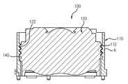
도 1은 본 발명의 일실시예에 따른 보이스 코일 모터용 가동자를 도시한 단면도이다.
도 2는 도 1의 'A' 부분 확대도이다.
도 3은 본 발명의 다른 실시예에 따른 보이스 코일 모터용 가동자의 렌즈를 도시한 측면도이다.
도 4는 도 1에 도시된 보이스 코일 모터용 가동자를 포함하는 보이스 코일 모터의 분해 사시도이다.
도 5는 도 4를 조립한 후 가동자 부분을 확대 도시한 확대도이다.1 is a cross-sectional view showing a mover for a voice coil motor according to an embodiment of the present invention.
FIG. 2 is an enlarged view of a portion 'A' of FIG. 1.
3 is a side view illustrating a lens of a mover for a voice coil motor according to another embodiment of the present invention.
FIG. 4 is an exploded perspective view of the voice coil motor including the mover for the voice coil motor shown in FIG. 1.
FIG. 5 is an enlarged view illustrating the movable part after assembling FIG. 4.
이하, 첨부된 도면들을 참조하여 본 발명에 따른 실시예를 상세히 설명한다. 이 과정에서 도면에 도시된 구성요소의 크기나 형상 등은 설명의 명료성과 편의상 과장되게 도시될 수 있다. 또한, 본 발명의 구성 및 작용을 고려하여 특별히 정의된 용어들은 사용자, 운용자의 의도 또는 관례에 따라 달라질 수 있다. 이러한 용어들에 대한 정의는 본 명세서 전반에 걸친 내용을 토대로 본 발명의 기술적 사상에 부합하는 의미와 개념으로 해석되어야 한다.Hereinafter, exemplary embodiments of the present invention will be described in detail with reference to the accompanying drawings. The sizes and shapes of the components shown in the drawings may be exaggerated for clarity and convenience. In addition, terms defined in consideration of the configuration and operation of the present invention may be changed according to the intention or custom of the user, the operator. The definitions of these terms should be interpreted based on the contents of the present specification and meanings and concepts in accordance with the technical idea of the present invention.
도 1은 본 발명의 일실시예에 따른 보이스 코일 모터용 가동자를 도시한 단면도이다. 도 2는 도 1의 'A' 부분 확대도이다.1 is a cross-sectional view showing a mover for a voice coil motor according to an embodiment of the present invention. FIG. 2 is an enlarged view of a portion 'A' of FIG. 1.
본 발명의 일실시예에 따른 보이스 코일 모터용 가동자는 동영상 및 디지털 이미지를 발생시키는 카메라의 이미지 센서 및 렌즈 사이의 간격을 조절하는 기능을 수행하는 보이스 코일 모터에 적용할 수 있다.The mover for a voice coil motor according to an embodiment of the present invention may be applied to a voice coil motor that performs a function of adjusting a distance between an image sensor and a lens of a camera that generates video and digital images.
도 1 및 도 2를 참조하면, 보이스 코일 모터용 가동자(100)는 렌즈 고정 유닛(110) 및 렌즈(120)를 포함한다.1 and 2, the
렌즈 고정 유닛(110)은 렌즈(120)를 고정하는 역할을 한다. 렌즈 고정 유닛(110)은 통 형상으로 형성될 수 있다. 렌즈 고정 유닛(110)은, 예를 들어, 원통 형상으로 형성될 수 있다.The
본 발명의 일실시예에서, 렌즈 고정 유닛(110) 및 렌즈(120)는, 예를 들어, 나사 체결 방식으로 결합될 수 있다.In one embodiment of the present invention, the
렌즈 고정 유닛(110)은 합성 수지를 사출 가공하여 형성될 수 있고, 렌즈 고정 유닛(110) 및 렌즈(120)를 나사 체결 방식으로 상호 체결하기 위해서 통 형상을 갖는 렌즈 고정 유닛(110)의 내주면에는 제1 나사부(112)가 형성된다. 본 발명의 일실시예에서, 제1 나사부(112)는, 예를 들어, 암나사부 또는 수나사부 중 어느 하나일 수 있다. 본 발명의 일실시예에서, 제1 나사부(112)는 암나사부이다.The
렌즈(120)는 렌즈 고정 유닛(110)의 내부에 고정되며, 렌즈(120)는 외부로부터 입사되어 이미지 센서 모듈로 출사되는 광의 광학 특성을 향상시킨다.The
렌즈(120)는, 예를 들어, 속이 찬 기둥 형상으로 형성될 수 있다. 본 발명의 일실시예에서, 렌즈(120)는 원통 형상으로 형성되며, 렌즈(120)의 외주면에는 제2 나사부(122)가 형성된다. 본 발명의 일실시예에서, 제2 나사부(122)는 제1 나사부(122)와 체결되며, 제2 나사부(122)는 암나사부 또는 수나사부 중 어느 하나일 수 있다.The
예를 들어, 렌즈 고정 유닛(110)의 제1 나사부(112)가 암나사부일 경우, 렌즈(120)의 제2 나사부(122)는 제1 나사부(112)와 체결되는 수나사부이다.For example, when the first threaded
렌즈 고정 유닛(110)의 제1 나사부(112) 및 렌즈(120)의 제2 나사부(122)는 상호 체결되기 위하여 미세한 갭(G)이 형성된다.The first threaded
제1 및 제2 나사부(112,122)들 사이의 갭이 클 경우, 렌즈(120)가 렌즈 고정 유닛(110)의 내부에서 유동 될 수 있고, 제1 및 제2 나사부(112,122)들 사이의 갭이 지나치게 작을 경우, 제1 및 제2 나사부(112,122)가 마찰되면서 이물질 또는 파티클이 발생될 수 있고, 제1 및 제2 나사부(112,122)들을 정확하게 체결하기 어렵다.When the gap between the first and
렌즈 고정 유닛(110)의 제1 나사부(112) 및 렌즈(120)의 제2 나사부(122) 사이에는 마찰 감소 부재(130)가 개재된다.The
마찰 감소 부재(130)는 제1 나사부(112) 및 제2 나사부(122) 사이에 개재되어 제1 및 제2 나사부(112,122)들 사이의 마찰 및 마모를 감소시켜 제1 및 제2 나사부(112,122)들로부터 이물질 또는 파티클이 발생되는 것을 억제 또는 방지한다.The
본 발명의 일실시예에서, 마찰 감소 부재(130)는 휘발되어 제1 및 제2 나사부(112,122)들로부터 제거되지 않는 비휘발성이면서 윤활 특성 및 제1 및 제2 나사부(112,122)들로부터 누설되지 않는 점성을 갖는 윤활유를 포함할 수 있다.In one embodiment of the present invention, the
한편, 마찰 감소 부재(130)는 점성을 갖고 자기장과 반응하는 자성 유체(magnetic fluid)를 포함할 수 있다. 마찰 감소 부재(130)가 자성 유체를 포함할 경우, 렌즈 고정 유닛(110)의 외주면에 배치된 코일 블럭에 의하여 흡입력을 받아 제1 및 제2 나사부(112,122)들 사이로 누설되는 것을 방지할 수 있다.Meanwhile, the
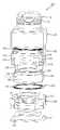
도 3은 본 발명의 다른 실시예에 따른 보이스 코일 모터용 가동자의 렌즈를 도시한 측면도이다.3 is a side view illustrating a lens of a mover for a voice coil motor according to another embodiment of the present invention.
도 1 및 도 3을 참조하면, 보이스 코일 모터용 가동자의 렌즈 고정 유닛(110)의 제1 나사부(112) 및 렌즈(120)의 제2 나사부(122) 사이에 마찰 감소 부재(130)를 원활하게 공급 및 제1 및 제2 나사부(112,122)들 사이에 마찰 감소 부재(130)가 균일하게 공급되도록 하기 위해 렌즈(120)의 외주면에 형성된 제2 나사부(122)는 단속적으로 절단된 절단부(124)가 형성되며, 절단부(124)는 렌즈(120)의 상단으로부터 하단을 향하는 방향으로 일렬로 형성된다.1 and 3, the
본 발명의 일실시예에서, 제2 나사부(122)에 형성된 절단부(124)는 각각 동일한 폭으로 형성될 수 있다. 이와 다르게 제2 나사부(122)에 형성된 절단부(124)는 서로 다른 폭으로 형성되어도 무방하다.In one embodiment of the present invention, the
마찰 감소 부재(130)는 절단부(124)를 통해 보다 원활하게 제1 및 제2 나사부(112,122)들 사이로 제공 및 분산된다.The
비록 본 발명의 일실시예에서는 렌즈(120)의 외주면에 형성된 제2 나사부(122)에 절단부(124)가 형성된 것이 도시 및 설명되고 있지만, 렌즈 고정 유닛(110)의 제1 나사부(112)에에 마찰 감소 부재(130)를 제공하기 위한 절단부를 형성하여도 무방하다.Although the
도 1을 다시 참조하면, 렌즈 고정 유닛(110)의 제1 나사부(112) 및 렌즈(120)의 제2 나사부(122) 사이에 개재된 마찰 감소 부재(130)가 보이스 코일 모터용 가동자(100)의 구동에 의하여 제1 및 제2 나사부(112,122)들 사이로 누설되는 것을 방지하기 위하여 제1 및 제2 나사산(112,122)들 중 적어도 하나에는 마찰 감소 부재(130)를 수납하는 탱크부(140)가 형성된다.Referring back to FIG. 1, the
마찰 감소 부재(130)를 제1 및 제2 나사부(112,122)들 사이에 저장하기 위해서 제1 나사부(112)의 일부는 제2 나사부(122)와 체결되지 않고 제2 나사부(122)와 체결되지 않은 제1 나사부(112)의 빈 공간에는 마찰 감소 부재(130)가 저장된다.In order to store the
한편, 제1 나사부(112)의 일부가 제2 나사부(122)와 체결되지 않도록 하기 위해 일렬로 형성된 제1 나사부(112)의 길이는 일렬로 형성된 상기 제2 나사부(122)의 길이보다 길게 형성되고, 제2 나사부(122)와 체결되지 않은 제1 나사부(112)의 빈 공간에 마찰 감소 부재(130)가 저장된다.On the other hand, the length of the first threaded
도 4는 도 1에 도시된 보이스 코일 모터용 가동자를 포함하는 보이스 코일 모터의 분해 사시도이다. 도 5는 도 4를 조립한 후 가동자 부분을 확대 도시한 확대도이다.FIG. 4 is an exploded perspective view of the voice coil motor including the mover for the voice coil motor shown in FIG. 1. FIG. 5 is an enlarged view illustrating the movable part after assembling FIG. 4.
도 4 및 도 5에 도시된 보이스 코일 모터는 오토 포커싱 기능 및 손떨림 보정 기능을 복합적으로 수행한다.The voice coil motor shown in FIGS. 4 and 5 performs an auto focusing function and a camera shake correction function in combination.
오토 포커싱 기능 및 손떨림 보정 기능을 복합적으로 수행하는 보이스 코일 모터(800)는 가동자(100), 고정자(200), 베이스(300) 및 탄성 부재(400)를 포함한다. 이에 더하여 보이스 코일 모터(800)는 커버 캔(500)을 더 포함할 수 있다.The
가동자(100)는 보빈(110, 또는 렌즈 고정 유닛), 렌즈(120) 및 마찰 감소 부재(130)를 포함한다. 이에 더하여 가동자(100)는 제1 자기장 발생 유닛(160)을 포함할 수 있다.The
가동자(100)는 후술 될 고정자(200)와의 작용에 의하여 베이스(300)의 상면에 대하여 업-다운되면서 오토 포커싱 기능을 수행 및 베이스(300)의 상부에서 틸팅 되면서 손떨림 보정 기능을 함께 수행한다.The
보빈(110)은, 예를 들어, 원통 형상으로 형성되며, 보빈(110)의 내주면에는 렌즈(120)와 결합되는 제1 나사부(112)가 형성된다. 본 발명의 일실시예에서, 제1 나사부(112)는, 예를 들어, 암나사부 또는 수나사부일 수 있다.The
본 발명의 일실시예에서, 보빈(110)의 내주면에 일렬로 형성된 제1 나사부(112)는 제1 길이로 형성될 수 있다.In one embodiment of the present invention, the
보빈(110)의 상면 및 상면과 대향 하는 하면에는 각각 후술 될 탄성 부재(400)와 결합하기 위한 결합 돌기(118)가 형성된다.Coupling
렌즈(120)는 보빈(110)의 내주면에 배치되며, 렌즈(120)의 외주면에는 보빈(110)의 형성된 제1 나사부(112)와 결합되는 제2 나사부(122)가 형성된다. 본 발명의 일실시예에서, 제1 나사부(112)가 암나사부일 경우, 제2 나사부(122)는 수나사부이다. 본 발명의 일실시예에서, 렌즈(120)의 외주면에 형성된 제2 나사부(122)는 제1 나사부(112)의 제1 길이보다 다소 짧은 제2 길이로 형성된다.The
따라서, 제1 나사부(112)에 제2 나사부(122)가 체결 되었을 때, 제1 나사부(112) 중 일부는 제2 나사부(122)와 결합되지 않은 빈 공간이 형성되고, 상기 빈 공간은 후술 될 마찰 감소 부재(130)를 수용하는 탱크부로서 역할한다.Therefore, when the second threaded
한편, 렌즈(120)의 외주면에 형성된 제2 나사부(122)의 일부를 절개하여 마찰 감소 부재(130)가 제1 및 제2 나사부(112,122)들의 사이로 원활하게 공급되도록 하는 것이 바람직하다.On the other hand, it is preferable to cut a part of the second threaded
마찰 감소 부재(130)는 보빈(110)의 제1 나사부(112) 및 렌즈(120)의 제2 나사부(122) 사이에 개재되어 제1 및 제2 나사부(112,122) 사이의 마찰력을 감소시켜 제1 및 제2 나사부(112,122)로부터 이물질 또는 파티클이 발생 되는 것을 방지한다.The
본 발명의 일실시예에서, 마찰 감소 부재(130)는 비휘발성 및 점성을 갖는 윤활유 또는 자력에 의하여 제1 및 제2 나사부(112,122)로부터 누설되지 않는 자성 유체를 포함할 수 있다.In one embodiment of the present invention, the
한편, 보빈(110)의 외주면은 곡선 구간 및 직선 구간이 교대로 형성된 형상으로 형성되며, 보빈(110)의 외주면에는, 예를 들어, 4 개의 직선 구간들 및 4 개의 곡선 구간들이 교대로 형성된다.Meanwhile, the outer circumferential surface of the
제1 자기장 발생 유닛(160)은 보빈(110)의 외주면에 형성된 직선 구간들에 결합 된다. 예를 들어, 제1 자기장 발생 유닛(160)은 보빈(110)의 외주면에 형성된 4 개의 직선 구간들 중 상호 대향 하는 2 개의 직선 구간들 또는 4 개의 직선 구간들에 상호 대향 하게 배치될 수 있다. 제1 자기장 발생 유닛(160)은, 예를 들어, 2극 또는 4극 플랫 마그네트를 포함할 수 있다.The first magnetic
본 발명의 일실시예에서, 제1 자기장 발생 유닛(160)이 보빈(110)의 외주면에 장착되어 업-다운되면서 오토 포커싱 기능을 수행 및/또는 베이스(300)에 대하여 틸팅 되면서 손떨림 보정 기능을 반복하여 수행할 경우, 제1 자기장 발생 유닛(160)이 보빈(110)의 외주면으로부터 이탈될 수 있다.In one embodiment of the present invention, the first magnetic
제1 자기장 발생 유닛(160)이 보빈(110)의 외주면으로부터 이탈되는 것을 방지하기 위해 제1 자기장 발생 유닛(160) 및 보빈(110)의 사이에는 접착제가 개재될 수 있다.An adhesive may be interposed between the first magnetic
고정자(200)는 하우징(210), 제2 자기장 발생 유닛(220) 및 단자 플레이트(230)를 포함한다.The
하우징(210)은, 예를 들어, 상면 및 하면이 개구된 통 형상으로 형성된다.The
하우징(210)의 내부에는 가동자(100)가 배치되며, 하우징(210)은 가동자(100)의 보빈(110)의 외주면에 배치된 제1 자기장 발생 유닛(160)을 감싼다.The
본 발명의 일실시예에서, 하우징(210)은, 예를 들어, 4 개의 측벽(212)들을 포함하는 사각 통 형상으로 형성된다. 하우징(210)은, 예를 들어, 합성 수지를 이용한 사출공정에 의하여 형성될 수 있다.In one embodiment of the invention, the
제2 자기장 발생 유닛(220)은 에나멜 수지와 같은 절연 수지에 의하여 코팅된 긴 길이의 전선을 권선하여 형성된 코일 블럭을 포함한다. 본 발명의 일실시예에서, 제2 자기장 발생 유닛(220)은, 사각 프레임 형상으로 권선 되며, 제2 자기장 발생 유닛(220)의 일측단 및 상기 일측단과 대향 하는 타측단은 각각 제2 자기장 발생 유닛(220)에 대하여 상호 반대 방향으로 배치된다.The second magnetic
예를 들어, 제2 자기장 발생 유닛(220)의 상기 일측단은 제2 자기장 발생 유닛(220)의 왼쪽에 배치되고, 제2 자기장 발생 유닛(220)의 상기 타측단은 제2 자기장 발생 유닛(220)의 오른쪽에 배치된다.For example, the one end of the second magnetic
제2 자기장 발생 유닛(220)은 전선을 권선 하여 형성하기 때문에 소정 두께를 갖고, 두께를 갖는 제2 자기장 발생 유닛(220)이 하우징(210)의 측벽(212) 상에 배치될 경우, 복합 기능 보이스 코일 모터(800)의 두께가 증가 될 수 있다.Since the second magnetic
본 발명의 일실시예에서는 제2 자기장 발생 유닛(220)에 기인한 보이스 코일 모터(800)의 부피 증가를 방지하기 위하여 하우징(210)의 측벽(212)의 외측면 중 가동자(100)의 제1 자기장 발생 유닛(160)과 대응하는 부분에는 수납홈(214)이 형성된다.In an embodiment of the present invention, in order to prevent the volume increase of the
각 제1 자기장 발생 유닛(160)과 대응하는 고정자(200)의 하우징(210)에 결합된 제2 자기장 발생 유닛(220)들 중 상호 마주하는 제2 자기장 발생 유닛(220)에 구동 전류를 인가함에 따라 가동자(100)는 베이스(300)에 대하여 업-다운 되면서 오토 포커싱 기능을 수행하고, 하우징(210)에 결합된 제2 자기장 발생 유닛(220) 중 상호 마주하지 않고 인접하게 배치된 제2 자기장 발생 유닛(220)들에 구동 전류를 인가함에 따라 가동자(100)는 베이스(300)에 대하여 틸팅되면서 손떨림 보정 기능을 수행한다.A driving current is applied to each of the first magnetic
하우징(210)의 측벽(212)의 외측면에 형성된 수납홈(214)은 제2 자기장 발생 유닛(220)의 형상에 대응하는 형상으로 형성되며, 제2 자기장 발생 유닛(220)이 하우징(210)의 측벽(212)의 외측면으로부터 돌출되는 것을 방지하기 위해 수납홈(214)의 깊이는 제2 자기장 발생 유닛(220)의 두께 이상으로 형성되는 것이 바람직하다.The receiving
본 발명의 일실시예에서는 하우징(210)의 측벽(212)의 외측면에 홈 형상의 수납홈(214)이 형성되는 것이 도시 및 설명되고 있지만, 제1 자기장 발생 유닛(160)과 대응하는 하우징(210)에 제2 자기장 발생 유닛(220)을 수납하는 관통홀을 형성하여도 무방하다.In one embodiment of the present invention, although the groove-shaped
한편, 하우징(210)에 각 제1 자기장 발생 유닛(160)과 대응하는 제2 자기장 발생 유닛(220)을 배치할 경우, 제2 자기장 발생 유닛(220)에 구동 신호를 제공하기 어렵다. 특히 하우징(210)을 합성 수지로 제작할 경우 후술 될 베이스(300)의 후면에 배치된 회로기판(310)으로부터 제2 자기장 발생 유닛(220)에 구동 신호를 전달하기 더욱 어렵다.On the other hand, when the second magnetic
단자 플레이트(230)는 베이스(300)의 후면에 배치된 회로기판(310)으로부터 제공된 구동 신호를 제2 자기장 발생 유닛(220)으로 전달한다.The
단자 플레이트(230)는 얇은 두께로 형성된 금속 플레이트 형태로 제작되며, 단자 플레이트(230) 중 제2 자기장 발생 유닛(220)과 접속되는 일부 또는 전부에는 후술 될 제2 자기장 발생 유닛(220)과의 접속 특성을 향상시키기 위해 도금층이 형성될 수 있다.The
단자 플레이트(230)는 하우징(210)의 측벽(212)과 평행하게 형성되며, 단자 플레이트(230)는 인서트 사출 공정에 의하여 하우징(210)과 일체로 형성될 수 있다.The
하우징(210)에 인서트 된 단자 플레이트(230)의 일부는 제2 자기장 발생 유닛(220)을 수납하는 수납홈(214)에 의하여 노출되고, 노출된 단자 플레이트(230)는 제2 자기장 발생 유닛(220)의 양쪽 단부와 전기적으로 접속된다. 단자 플레이트(230) 및 제2 자기장 발생 유닛(220)은, 예를 들어, 솔더 또는 도전성 접착제 등에 의하여 상호 접속될 수 있다.A portion of the
본 발명의 일실시예에서는 하우징(210)에 인서트 된 단자 플레이트(230)가 설명되고 있지만, 이와 다르게 단자 플레이트(230)는 하우징(210)에 형성된 삽입홈에 삽입되어 고정되어도 무방하다.In an embodiment of the present invention, the
단자 플레이트(230)는 베이스(300)를 통과하여 회로 기판(310)에 전기적으로 접속될 수 있도록 하우징(210)의 하면으로부터 소정 길이 돌출된다. 이때, 베이스(300)의 하면으로부터 돌출된 단자 플레이트(230)는 하우징(210)의 측벽(212)과 평행한 방향으로 배치될 수 있다. 이와 다르게, 베이스(300)의 하면으로부터 돌출된 단자 플레이트(230)는 베이스(300)의 하면과 평행한 방향으로 절곡 될 수 있다.The
베이스(300)는 직육면체 형상으로 형성되며, 베이스(300)의 중앙부에는 개구(305)가 형성되고, 베이스(300)로부터는 하우징(200)과 결합되기 위한 결합 기둥(301)이 돌출된다. 베이스(300)의 결합 기둥(301) 및 결합 기둥(301)과 대응하는 하우징(200)에 형성된 결합홈(216)은 상호 끼워 맞춤 방식으로 결합 된다.The
베이스(300)의 후면에는 IR 필터 및 렌즈(120)와 마주하는 이미지 센서 모듈이 장착될 수 있다.An image sensor module facing the IR filter and the
회로 기판(310)의 접속 단자(312) 및 접속 단자(312)에 배치된 단자 플레이트(230)는 상호 솔더 또는 도전성 접착제에 의하여 상호 결합 된다.The
본 발명의 일실시예에서, 단자 플레이트(230)의 단부가 절곡 되지 않을 경우, 단자 플레이트(230)의 단부는 접속 단자(312)에 형성된 삽입홀 내에 배치되고, 삽입홀 내에 배치된 단자 플레이트(230) 및 접속 단자(312)는 솔더 또는 도전성 접착제에 의하여 상호 결합 된다.In one embodiment of the present invention, when the end of the
탄성 부재(400)는 제1 탄성 부재(410) 및 제2 탄성 부재(420)를 포함한다.The
제1 탄성 부재(410)는 가동자(100)의 보빈(110)의 하면으로부터 돌출된 돌기에 결합 되며, 제1 탄성 부재(410)는 베이스(300) 및 하우징(200) 사이에 고정된다. 본 발명의 일실시예에서, 제1 탄성 부재(410)는, 예를 들어, 판 스프링을 포함할 수 있다.The first
제2 탄성 부재(420)는 가동자(100)의 보빈(110)의 상면으로부터 돌출된 돌기에 결합 된다. 제2 탄성 부재(410)는, 예를 들어, 판 스프링을 포함할 수 있다.The second
커버 캔(500)은 사각 통 형상으로 형성되며, 커버 캔(500)의 하면은 완전히 개구되고, 커버 캔(500)의 상면에는 가동자(100)의 보빈(110)을 노출하는 개구가 형성된다.The cover can 500 is formed in a rectangular cylindrical shape, and a bottom surface of the cover can 500 is completely opened, and an opening for exposing the
커버 캔(500)은 제2 자기장 발생 유닛(220)으로부터 발생 되는 유해 전자파를 차단 또는 외부의 전자파가 가동자(100)로 유입되는 것을 차단하며, 커버 캔(500)은, 예를 들어, 금속판을 프레스 가공하여 형성될 수 있다.The cover can 500 blocks harmful electromagnetic waves generated from the second magnetic
이상에서 상세하게 설명한 바에 의하면, 외부광을 이미지 센서로 전달하는 렌즈의 외주면에 형성된 나사부 및 렌즈를 고정하는 렌즈 고정 유닛에 형성된 나사부가 상호 체결될 때 나사부들끼리 접촉, 마찰 또는 마모되어 이물질 및 파티클이 이미지 센서로 낙하하여 영상 또는 이미지 품질 저하가 발생되는 것을 방지할 수 있다.As described in detail above, when the screw portions formed on the outer peripheral surface of the lens for transmitting external light to the image sensor and the screw portions formed on the lens fixing unit for fixing the lens are screwed together, the threads are contacted, rubbed, or worn, resulting in foreign matter and particles. Falling to this image sensor can prevent an image or image quality deterioration from occurring.
이상에서 본 발명에 따른 실시예들이 설명되었으나, 이는 예시적인 것에 불과하며, 당해 분야에서 통상적 지식을 가진 자라면 이로부터 다양한 변형 및 균등한 범위의 실시예가 가능하다는 점을 이해할 것이다. 따라서, 본 발명의 진정한 기술적 보호 범위는 다음의 특허청구범위에 의해서 정해져야 할 것이다.
While the invention has been shown and described with reference to certain preferred embodiments thereof, it will be understood by those skilled in the art that various changes and modifications may be made without departing from the spirit and scope of the invention as defined by the appended claims. Accordingly, the true scope of the present invention should be determined by the following claims.
800...보이스 코일 모터100...가동자
200...고정자300...베이스
400...탄성 부재500...커버캔800 ...
200 ...
400 ...
Claims (17)
Translated fromKorean외주면에 상기 제1 나사부와 체결되는 제2 나사부가 형성된 렌즈를 포함하며,
상기 제1 및 제2 나사부들 사이에는 마찰 감소 부재가 개재된 보이스 코일 모터용 가동자.A lens fixing unit having a first screw portion formed on an inner circumferential surface thereof; And
It includes a lens formed on the outer circumferential surface and the second screw portion is fastened to the first screw portion,
A mover for a voice coil motor having a friction reducing member interposed between the first and second threads.
상기 마찰 감소 부재는 윤활유를 포함하는 보이스 코일 모터용 가동자.The method of claim 1,
And the friction reducing member includes a lubricant.
상기 윤활유는 비휘발성 윤활유를 포함하는 보이스 코일 모터용 가동자.The method of claim 2,
The lubricant is a mover for a voice coil motor comprising a nonvolatile lubricant.
상기 제1 나사부 및 상기 제2 나사부 사이에 상기 마찰 감소 부재를 주입하기 위해 상기 렌즈 고정 유닛에는 상기 내주면의 상단으로부터 상기 상단과 대향하는 하단을 향해 상기 제1 나사부를 지정된 폭으로 절단한 절단부가 형성된 보이스 코일 모터용 가동자.The method of claim 1,
In order to inject the friction reducing member between the first threaded portion and the second threaded portion, the lens fixing unit has a cut portion formed by cutting the first threaded portion at a predetermined width from an upper end of the inner circumferential surface toward a lower end facing the upper end. Movable for voice coil motor.
상기 제1 나사부의 일부는 상기 제2 나사부와 체결되지 않고 상기 제2 나사부와 체결되지 않은 상기 제1 나사부의 빈 공간에 상기 마찰 감소 부재가 저장되는 보이스 코일 모터용 가동자.The method of claim 1,
And the friction reducing member is stored in a vacant space of the first threaded portion that is not fastened with the second threaded portion and the part of the first threaded portion is not fastened to the second threaded portion.
일렬로 형성된 상기 제1 나사부의 길이는 일렬로 형성된 상기 제2 나사부의 길이보다 길게 형성되어 상기 제2 나사부와 체결되지 않은 상기 제1 나사부의 빈 공간에 상기 마찰 감소 부재가 저장되는 보이스 코일 모터용 가동자.The method of claim 1,
The length of the first threaded portion formed in a row is longer than the length of the second threaded portion formed in a line for the voice coil motor in which the friction reducing member is stored in an empty space of the first threaded portion that is not engaged with the second threaded portion Mover.
상기 마찰 감소 부재는 점성을 갖고 자기장과 반응하는 자성 유체(magnetic fluid)를 포함하는 보이스 코일 모터용 가동자.The method of claim 1,
And the friction reducing member is viscous and includes a magnetic fluid reacting with the magnetic field.
외주면에 상기 제1 나사부와 체결되는 제2 나사부가 형성된 렌즈를 포함하며,
상기 제1 및 제2 나사부를 체결하는 동안 상기 제1 나사부 및 상기 제2 나사부의 마찰에 의한 이물질이 발생 되지 않도록 상기 제1 나사부 및 상기 제2 나사부의 마찰을 감소시킨 보이스 코일 모터용 가동자.A lens fixing unit having a first screw portion formed on an inner circumferential surface thereof; And
It includes a lens formed on the outer circumferential surface and the second screw portion is fastened to the first screw portion,
And the friction of the first screw part and the second screw part is reduced so that foreign matters caused by the friction of the first screw part and the second screw part are not generated while the first and second screw parts are tightened.
상기 제1 나사부 및 상기 제2 나사부의 사이에는 상기 마찰을 감소시키기 위한 마찰 감소 부재가 개재된 보이스 코일 모터용 가동자.9. The method of claim 8,
And a friction reducing member for reducing the friction between the first threaded portion and the second threaded portion.
상기 마찰 감소 부재는 점성을 갖는 비휘발성 윤활유를 포함하는 보이스 코일 모터용 가동자.9. The method of claim 8,
And the friction reducing member includes a viscous non-volatile lubricant.
상기 마찰 감소 부재는 점성을 갖는 자성 유체를 포함하는 보이스 코일 모터용 가동자.9. The method of claim 8,
And the friction reducing member includes a viscous magnetic fluid.
상기 제1 자기장 발생 유닛과 마주하며 제2 자기장을 발생시키는 제2 자기장 발생 유닛을 포함하는 고정자;
상기 가동자를 탄력적으로 지지하는 탄성 부재; 및
상기 고정자를 지지하는 베이스를 포함하는 보이스 코일 모터.A lens fixing unit having a first threaded portion formed on an inner circumferential surface, a lens formed with a second threaded portion fastened to the first threaded portion on an outer circumferential surface, a friction reducing member interposed between the first threaded portion and the second threaded portion, and A mover including a first magnetic field generating unit coupled to an outer circumferential surface to generate a first magnetic field;
A stator facing the first magnetic field generating unit and including a second magnetic field generating unit generating a second magnetic field;
An elastic member for elastically supporting the mover; And
A voice coil motor comprising a base for supporting the stator.
상기 마찰 감소 부재는 비휘발성 윤활유 및 자성 유체 중 어느 하나를 포함하는 보이스 코일 모터.The method of claim 12,
And the friction reducing member comprises any one of a nonvolatile lubricant and a magnetic fluid.
상기 제1 나사부 및 상기 제2 나사부 사이에 상기 마찰 감소 부재를 주입하기 위해 상기 렌즈 고정 유닛에는 상기 내주면의 상단으로부터 상기 상단과 대향하는 하단을 향해 상기 제1 나사부를 지정된 폭으로 절단한 탱크부가 형성된 보이스 코일 모터.The method of claim 12,
In order to inject the friction reducing member between the first threaded portion and the second threaded portion, the lens fixing unit has a tank portion in which the first threaded portion is cut in a predetermined width from an upper end of the inner circumferential surface toward a lower end facing the upper end. Voice coil motor.
상기 제1 나사부의 일부는 상기 제2 나사부와 체결되지 않고 상기 제2 나사부와 체결되지 않은 상기 제1 나사부의 빈 공간에 상기 마찰 감소 부재가 저장되는 보이스 코일 모터.The method of claim 12,
The voice coil motor in which the friction reducing member is stored in an empty space of the first threaded portion that is not fastened with the second threaded portion and is not fastened to the second threaded portion.
일렬로 형성된 상기 제1 나사부의 길이는 일렬로 형성된 상기 제2 나사부의 길이보다 길게 형성되어 상기 제2 나사부와 체결되지 않은 상기 제1 나사부의 빈 공간에 상기 마찰 감소 부재가 저장되는 보이스 코일 모터.The method of claim 12,
The length of the first threaded portion formed in a row is formed longer than the length of the second threaded portion formed in a voice coil motor in which the friction reducing member is stored in the empty space of the first threaded portion that is not engaged with the second threaded portion.
상기 제1 자기장 발생 유닛은 마그네트를 포함하고, 상기 제2 자기장 발생 유닛은 상기 마그네트와 마주하는 코일 블럭을 포함하는 보이스 코일 모터.The method of claim 12,
The first magnetic field generating unit includes a magnet, and the second magnetic field generating unit includes a coil block facing the magnet.
Priority Applications (1)
| Application Number | Priority Date | Filing Date | Title |
|---|---|---|---|
| KR1020110012933AKR101875586B1 (en) | 2011-02-14 | 2011-02-14 | Mover for voice coil motro and voice coil motor having the same |
Applications Claiming Priority (1)
| Application Number | Priority Date | Filing Date | Title |
|---|---|---|---|
| KR1020110012933AKR101875586B1 (en) | 2011-02-14 | 2011-02-14 | Mover for voice coil motro and voice coil motor having the same |
Publications (2)
| Publication Number | Publication Date |
|---|---|
| KR20120092968Atrue KR20120092968A (en) | 2012-08-22 |
| KR101875586B1 KR101875586B1 (en) | 2018-07-09 |
Family
ID=46884740
Family Applications (1)
| Application Number | Title | Priority Date | Filing Date |
|---|---|---|---|
| KR1020110012933AActiveKR101875586B1 (en) | 2011-02-14 | 2011-02-14 | Mover for voice coil motro and voice coil motor having the same |
Country Status (1)
| Country | Link |
|---|---|
| KR (1) | KR101875586B1 (en) |
Family Cites Families (18)
| Publication number | Priority date | Publication date | Assignee | Title |
|---|---|---|---|---|
| JPS6084516A (en)* | 1983-10-15 | 1985-05-13 | Olympus Optical Co Ltd | Helicoid device of lens barrel |
| JPS612113A (en)* | 1984-06-14 | 1986-01-08 | Hitachi Ltd | Lens barrel and its production |
| JP3675026B2 (en)* | 1996-03-29 | 2005-07-27 | 松下電器産業株式会社 | Lens moving device |
| JP2006332814A (en)* | 2005-05-24 | 2006-12-07 | Smk Corp | The camera module |
| KR100716789B1 (en)* | 2005-10-28 | 2007-05-14 | 삼성전기주식회사 | Camera module |
| KR20080057806A (en)* | 2006-12-21 | 2008-06-25 | 엘지이노텍 주식회사 | Camera module with bonding escape groove |
| KR101224679B1 (en)* | 2007-01-12 | 2013-01-21 | 엘지이노텍 주식회사 | Assembly torque control type camera module |
| TWM325524U (en)* | 2007-03-20 | 2008-01-11 | Tricore Corp | Improvement of driving and positing assignment for focusing actuator |
| JP3135568U (en)* | 2007-07-10 | 2007-09-20 | 台灣東電化股▲ふん▼有限公司 | Micro lens activity mechanism protection structure |
| CN101896719A (en)* | 2007-10-30 | 2010-11-24 | 剑桥机电有限公司 | Shape memory alloy actuation apparatus |
| JP5544470B2 (en)* | 2008-02-01 | 2014-07-09 | カンタツ株式会社 | Imaging lens unit |
| KR20090131925A (en)* | 2008-06-19 | 2009-12-30 | 엘지이노텍 주식회사 | Camera module |
| KR100972435B1 (en)* | 2008-09-22 | 2010-07-26 | 삼성전기주식회사 | Camera module |
| KR100919118B1 (en)* | 2008-10-17 | 2009-09-25 | (주)차바이오앤디오스텍 | Autofocus Lens Assembly with Actuator with Self-tightening Means |
| JP5295875B2 (en)* | 2008-11-06 | 2013-09-18 | シャープ株式会社 | Camera module, electronic device including the same, and lens positioning method for camera module |
| KR101592930B1 (en)* | 2009-05-28 | 2016-02-11 | (주)하이소닉 | Compact camera module |
| KR101005772B1 (en)* | 2009-05-18 | 2011-01-06 | 주식회사 하이소닉 | Miniature camera module |
| JP5292181B2 (en)* | 2009-05-26 | 2013-09-18 | 富士フイルム株式会社 | Sliding member structure and manufacturing method thereof |
- 2011
- 2011-02-14KRKR1020110012933Apatent/KR101875586B1/enactiveActive
Also Published As
| Publication number | Publication date |
|---|---|
| KR101875586B1 (en) | 2018-07-09 |
Similar Documents
| Publication | Publication Date | Title |
|---|---|---|
| KR101804575B1 (en) | Multi-function voice coil motor | |
| US9035502B2 (en) | Multifunctional voice coil motor | |
| KR101847649B1 (en) | Multi-function voice coil motor | |
| US9632280B2 (en) | Lens actuator having autofocus function and hand-shake correction function | |
| KR100662238B1 (en) | Lens assembly with drive means and autofocus adjusting device comprising the same | |
| KR100649638B1 (en) | Lens transport device with improved assembly | |
| KR101931183B1 (en) | Voice coil motor | |
| KR101072404B1 (en) | Camera autofocus control without yoke | |
| KR101848500B1 (en) | Multi-function voice coil motor | |
| KR20130012437A (en) | Voice coil motor | |
| KR20140059329A (en) | Voice coil motor | |
| KR20120133905A (en) | Multi-funtion voice coil motor | |
| KR101950020B1 (en) | Voice coil motor | |
| KR101804574B1 (en) | Multi-function voice coil motor | |
| KR20170025936A (en) | Unit for actuating lens, camera module, and optical apparatus | |
| KR101805919B1 (en) | Voice coil motor | |
| KR20120092968A (en) | Mover for voice coil motro and voice coil motor having the same | |
| KR101959541B1 (en) | Voice coil motor | |
| KR101988584B1 (en) | Voice coil motor | |
| KR20140025635A (en) | Voice coil motor | |
| KR20130044497A (en) | Voice coil motor | |
| KR102221905B1 (en) | Voice coil motor | |
| KR102131410B1 (en) | Voice coil motor | |
| KR101908037B1 (en) | Voice coil motor | |
| KR101912385B1 (en) | Voice coil motor |
Legal Events
| Date | Code | Title | Description |
|---|---|---|---|
| PA0109 | Patent application | Patent event code:PA01091R01D Comment text:Patent Application Patent event date:20110214 | |
| PG1501 | Laying open of application | ||
| A201 | Request for examination | ||
| PA0201 | Request for examination | Patent event code:PA02011R01I Patent event date:20110214 Comment text:Patent Application | |
| E902 | Notification of reason for refusal | ||
| PE0902 | Notice of grounds for rejection | Comment text:Notification of reason for refusal Patent event date:20170626 Patent event code:PE09021S01D | |
| E90F | Notification of reason for final refusal | ||
| PE0902 | Notice of grounds for rejection | Comment text:Final Notice of Reason for Refusal Patent event date:20171206 Patent event code:PE09021S02D | |
| E701 | Decision to grant or registration of patent right | ||
| PE0701 | Decision of registration | Patent event code:PE07011S01D Comment text:Decision to Grant Registration Patent event date:20180502 | |
| GRNT | Written decision to grant | ||
| PR0701 | Registration of establishment | Comment text:Registration of Establishment Patent event date:20180702 Patent event code:PR07011E01D | |
| PR1002 | Payment of registration fee | Payment date:20180703 End annual number:3 Start annual number:1 | |
| PG1601 | Publication of registration | ||
| PR1001 | Payment of annual fee | Payment date:20210615 Start annual number:4 End annual number:4 | |
| PR1001 | Payment of annual fee | Payment date:20220614 Start annual number:5 End annual number:5 | |
| PR1001 | Payment of annual fee | Payment date:20240617 Start annual number:7 End annual number:7 | |
| PR1001 | Payment of annual fee | Payment date:20250616 Start annual number:8 End annual number:8 |