KR20120080493A - Method and apparatus for transmitting and receiving measurement pattern in comp system - Google Patents
Method and apparatus for transmitting and receiving measurement pattern in comp systemDownload PDFInfo
- Publication number
- KR20120080493A KR20120080493AKR1020110001995AKR20110001995AKR20120080493AKR 20120080493 AKR20120080493 AKR 20120080493AKR 1020110001995 AKR1020110001995 AKR 1020110001995AKR 20110001995 AKR20110001995 AKR 20110001995AKR 20120080493 AKR20120080493 AKR 20120080493A
- Authority
- KR
- South Korea
- Prior art keywords
- base station
- pattern
- user terminal
- signal
- abs pattern
- Prior art date
- Legal status (The legal status is an assumption and is not a legal conclusion. Google has not performed a legal analysis and makes no representation as to the accuracy of the status listed.)
- Withdrawn
Links
Images


Classifications
- H—ELECTRICITY
- H04—ELECTRIC COMMUNICATION TECHNIQUE
- H04W—WIRELESS COMMUNICATION NETWORKS
- H04W24/00—Supervisory, monitoring or testing arrangements
- H04W24/06—Testing, supervising or monitoring using simulated traffic
- H—ELECTRICITY
- H04—ELECTRIC COMMUNICATION TECHNIQUE
- H04B—TRANSMISSION
- H04B7/00—Radio transmission systems, i.e. using radiation field
- H04B7/02—Diversity systems; Multi-antenna system, i.e. transmission or reception using multiple antennas
- H04B7/022—Site diversity; Macro-diversity
- H04B7/024—Co-operative use of antennas of several sites, e.g. in co-ordinated multipoint or co-operative multiple-input multiple-output [MIMO] systems
- H—ELECTRICITY
- H04—ELECTRIC COMMUNICATION TECHNIQUE
- H04B—TRANSMISSION
- H04B7/00—Radio transmission systems, i.e. using radiation field
- H04B7/02—Diversity systems; Multi-antenna system, i.e. transmission or reception using multiple antennas
- H04B7/04—Diversity systems; Multi-antenna system, i.e. transmission or reception using multiple antennas using two or more spaced independent antennas
- H04B7/06—Diversity systems; Multi-antenna system, i.e. transmission or reception using multiple antennas using two or more spaced independent antennas at the transmitting station
- H04B7/0613—Diversity systems; Multi-antenna system, i.e. transmission or reception using multiple antennas using two or more spaced independent antennas at the transmitting station using simultaneous transmission
- H04B7/0615—Diversity systems; Multi-antenna system, i.e. transmission or reception using multiple antennas using two or more spaced independent antennas at the transmitting station using simultaneous transmission of weighted versions of same signal
- H04B7/0619—Diversity systems; Multi-antenna system, i.e. transmission or reception using multiple antennas using two or more spaced independent antennas at the transmitting station using simultaneous transmission of weighted versions of same signal using feedback from receiving side
- H—ELECTRICITY
- H04—ELECTRIC COMMUNICATION TECHNIQUE
- H04L—TRANSMISSION OF DIGITAL INFORMATION, e.g. TELEGRAPHIC COMMUNICATION
- H04L5/00—Arrangements affording multiple use of the transmission path
- H04L5/003—Arrangements for allocating sub-channels of the transmission path
- H04L5/0032—Distributed allocation, i.e. involving a plurality of allocating devices, each making partial allocation
- H04L5/0035—Resource allocation in a cooperative multipoint environment
- H—ELECTRICITY
- H04—ELECTRIC COMMUNICATION TECHNIQUE
- H04W—WIRELESS COMMUNICATION NETWORKS
- H04W24/00—Supervisory, monitoring or testing arrangements
- H04W24/08—Testing, supervising or monitoring using real traffic
- H—ELECTRICITY
- H04—ELECTRIC COMMUNICATION TECHNIQUE
- H04W—WIRELESS COMMUNICATION NETWORKS
- H04W72/00—Local resource management
- H04W72/04—Wireless resource allocation
- H04W72/044—Wireless resource allocation based on the type of the allocated resource
- H04W72/0446—Resources in time domain, e.g. slots or frames
Landscapes
- Engineering & Computer Science (AREA)
- Signal Processing (AREA)
- Computer Networks & Wireless Communication (AREA)
- Mobile Radio Communication Systems (AREA)
Abstract
Translated fromKorean
Description
Translated fromKorean본 발명은 무선 통신 시스템에 관한 것으로, 보다 상세하게는 둘 이상의 기지국들이 협력하여 신호를 전송하는 협력형 다중 셀 통신시스템에서 각각의 기지국이 둘 이상의 전송 안테나들을 구비하고 하나 이상의 기지국이 단말로부터 채널 정보를 수신하여 다중 안테나 전송을 수행하는 협력형 다중 셀 통신시스템 및 통신방법에 대한 것이다.The present invention relates to a wireless communication system, and more particularly, in a cooperative multi-cell communication system in which two or more base stations cooperate to transmit a signal, each base station includes two or more transmission antennas and one or more base stations transmit channel information from a terminal. A cooperative multi-cell communication system and communication method for receiving a multi-antenna transmission.
통신 시스템이 발전해나감에 따라 사업체들 및 개인들과 같은 소비자들은 매우 다양한 무선 단말기들을 사용하게 되었다.As communication systems have evolved, consumers, such as businesses and individuals, have used a wide variety of wireless terminals.
따라서, 통신 서비스 사업자들은 무선 단말기들에 대한 새로운 통신 서비스 시장을 창출하고, 신뢰성 있으면서도 저렴한 서비스를 제공하여 기존의 통신 서비스 시장을 확대시키려는 시도를 계속하고 있다.Accordingly, communication service providers are continuously attempting to expand the existing communication service market by creating a new communication service market for wireless terminals and providing reliable and inexpensive services.
무선 통신 시스템의 통신 용량 증대를 위하여 다양한 기술들의 도입이 고려되고 있다. 기존의 무선 통신 시스템에 새로운 기법을 도입 시 가장 우선하여 고려되어야 할 부분은 새로운 기법의 도입으로 야기되는 용량의 증대와 새로운 기법의 도입에 의한 기존 사용자 또는 구형 단말의 통신 용량 감소 간 상관 관계를 고려하는 것이다. 즉, 기존의 시스템과의 호환성을 고려하되 새로운 시스템의 성능을 최대한 확장할 수 있도록 하는 방안이 필요하다.In order to increase the communication capacity of a wireless communication system, various technologies have been considered. The first consideration when introducing a new technique into an existing wireless communication system is considering the correlation between the increase in capacity caused by the introduction of the new technique and the reduction in the communication capacity of the existing user or the old terminal by the introduction of the new technique. It is. In other words, it is necessary to consider the compatibility with the existing system, but to expand the performance of the new system as much as possible.
본 발명은 무선통신 시스템에 관한 것으로, 다양한 전송 패턴을 가지는 사용자 단말 간에 간섭이 발생하지 않도록 측정 패턴을 송수신하는 방법 및 장치에 관한 것이다.The present invention relates to a wireless communication system, and to a method and apparatus for transmitting and receiving a measurement pattern so that interference does not occur between user terminals having various transmission patterns.
또한, 본 발명은 협력형 무선 통신 시스템의 사용자 단말과 기지국이 다른 유형의 사용자 단말과 신호 간섭을 줄이면서 또한 전송 효율을 높이고자 한다.In addition, the present invention is to improve the transmission efficiency while reducing the signal interference between the user terminal and the base station of the cooperative wireless communication system and other types of user terminal.
전술한 과제를 해결하기 위하여 본 발명의 일 실시예에 의한 협력형 무선 통신 시스템에서 신호의 송수신을 위한 측정 패턴을 송신하는 방법은 제 1 기지국 및 제 2 기지국이 제 1 사용자 단말에 협력형 통신을 제공하는 방법에 있어서, 상기 제 1 기지국이 오직 제 1 기지국과 일정 기간 동안 신호를 송수신하는 제 2 사용자 단말과의 신호 송수신을 위한 제 2 ABS 패턴을 설정하는 단계, 상기 제 2 ABS 패턴의 부분 집합이 되는 제 1 ABS 패턴을 상기 제 1 사용자 단말과의 신호 송수신을 위한 패턴으로 설정하는 단계, 상기 제 1 사용자 단말에 상기 제 1 ABS 패턴의 부분 집합을 측정 패턴으로 하여 상기 제 1 사용자 단말에게 상기 측정 패턴을 송신하는 단계, 및 상기 측정 패턴에 따라 상기 협력형 무선 통신 시스템을 위한 신호를 송신하는 단계를 포함한다.In order to solve the above problems, a method of transmitting a measurement pattern for transmitting and receiving a signal in a cooperative wireless communication system according to an embodiment of the present invention is that the first base station and the second base station performs cooperative communication with the first user terminal. A method of providing, the first base station setting a second ABS pattern for transmitting and receiving a signal with a second user terminal that transmits and receives only a signal with the first base station for a period of time, a subset of the second ABS pattern Setting the first ABS pattern to be a pattern for transmitting / receiving a signal with the first user terminal, wherein the subset of the first ABS pattern is measured as the measurement pattern to the first user terminal to the first user terminal; Transmitting a measurement pattern, and transmitting a signal for the cooperative wireless communication system in accordance with the measurement pattern.
본 발명의 다른 실시예에 의한 협력형 무선 통신 시스템에서 신호의 송수신을 위한 측정 패턴을 송신하는 방법은 제 1 기지국 및 제 2 기지국이 제 1 사용자 단말에 협력형 통신을 제공하는 방법에 있어서, 상기 제 1 기지국이 오직 제 1 기지국과 일정 기간 동안 신호를 송수신하는 제 2 사용자 단말과의 신호 송수신을 위한 제 2 ABS 패턴을 설정하는 단계, 상기 제 2 ABS 패턴에 대한 정보를 상기 제 2 기지국에 송신하는 단계, 및 오직 상기 제 2 기지국과 일정 기간 동안 신호를 송수신하는 제 3 사용자 단말과의 신호 송수신을 위한 제 3 ABS 패턴의 부분 집합이 되는 제 1 ABS 패턴에 대한 정보를 상기 제 2 기지국으로부터 수신하여 상기 제 1 사용자 단말과의 신호 송수신을 위한 패턴으로 설정하는 단계, 상기 제 1 사용자 단말에 상기 제 1 ABS 패턴의 부분 집합을 측정 패턴으로 하여 상기 제 1 사용자 단말에게 상기 측정 패턴을 송신하는 단계, 및 상기 측정 패턴에 따라 상기 협력형 무선 통신 시스템을 위한 신호를 송신하는 단계를 포함한다.In a method of transmitting a measurement pattern for transmitting and receiving a signal in a cooperative wireless communication system according to another embodiment of the present invention, in a method in which a first base station and a second base station provide cooperative communication to a first user terminal, Setting, by the first base station, a second ABS pattern for signal transmission and reception with a second user terminal that transmits and receives a signal only with the first base station for a predetermined period of time, and transmits information about the second ABS pattern to the second base station; And receiving, from the second base station, information on the first ABS pattern that is a subset of the third ABS pattern for transmitting and receiving a signal to and from a third user terminal that transmits and receives a signal to and from the second base station only for a predetermined period of time. Setting a pattern for transmitting / receiving a signal with the first user terminal to set a subset of the first ABS pattern in the first user terminal Transmitting the measurement pattern to the first user terminal as a measurement pattern, and transmitting a signal for the cooperative wireless communication system according to the measurement pattern.
본 발명의 또다른 실시예에 의한 협력형 무선 통신 시스템에서 신호의 송수신을 위한 측정 패턴을 수신하는 방법은 제 1 사용자 단말이 제 1 기지국 및 제 2 기지국과 협력형 통신을 수행하는 방법에 있어서, 상기 제 1 기지국으로부터 제 1 ABS 패턴의 부분 집합인 측정 패턴을 수신하는 단계, 및 상기 측정 패턴에 따라 상기 제 1 기지국 및 상기 제 2 기지국으로부터 송신되는 신호를 측정하여 측정 결과를 상기 제 1 기지국 또는 상기 제 2 기지국 중 어느 하나 이상에 송신하는 단계를 포함하며, 상기 제 1 ABS 패턴은 오직 제 1 기지국과 일정 기간 동안 신호를 송수신하는 제 2 사용자 단말과의 신호 송수신을 위한 제 2 ABS 패턴의 부분 집합인 것을 특징한다.In a method of receiving a measurement pattern for transmitting and receiving signals in a cooperative wireless communication system according to another embodiment of the present invention, in a method in which a first user terminal performs cooperative communication with a first base station and a second base station, Receiving a measurement pattern that is a subset of a first ABS pattern from the first base station, and measuring a signal transmitted from the first base station and the second base station according to the measurement pattern to obtain a measurement result from the first base station or And transmitting to any one or more of the second base stations, wherein the first ABS pattern is only part of a second ABS pattern for transmitting and receiving a signal with a second user terminal that transmits and receives a signal with the first base station for a period of time. It is a set.
본 발명의 또다른 실시예에 의한 협력형 무선 통신 시스템에서 신호의 송수신을 위한 측정 패턴을 송신하는 방법은 제 1 사용자 단말이 제 1 기지국 및 제 2 기지국과 협력형 통신을 수행하는 방법에 있어서, 상기 제 1 기지국으로부터 제 1 ABS 패턴의 부분 집합인 측정 패턴을 수신하는 단계, 및 상기 측정 패턴에 따라 상기 제 1 기지국 및 상기 제 2 기지국으로부터 송신되는 신호를 측정하여 측정 결과를 상기 제 1 기지국 또는 상기 제 2 기지국 중 어느 하나 이상에 송신하는 단계를 포함하며, 상기 제 1 ABS 패턴은 오직 제 2 기지국과 일정 기간 동안 신호를 송수신하는 제 2 사용자 단말과의 신호 송수신을 위한 제 2 ABS 패턴의 부분 집합인 것을 특징으로 한다.In a method of transmitting a measurement pattern for transmitting and receiving signals in a cooperative wireless communication system according to another embodiment of the present invention, in a method in which a first user terminal performs cooperative communication with a first base station and a second base station, Receiving a measurement pattern that is a subset of a first ABS pattern from the first base station, and measuring a signal transmitted from the first base station and the second base station according to the measurement pattern to obtain a measurement result from the first base station or And transmitting to any one or more of the second base stations, wherein the first ABS pattern is part of a second ABS pattern for signal transmission and reception with a second user terminal that transmits and receives a signal only with a second base station for a period of time. It is characterized by being a set.
본 발명의 또다른 실시예에 의한 기지국은 제 1 기지국 및 제 2 기지국이 제 1 사용자 단말에 협력형 통신을 제공하는 무선 통신 시스템에 있어서, 측정 패턴에 따라 상기 협력형 무선 통신 시스템을 위한 신호를 송신하는 송수신부, 상기 제 1 기지국이 오직 제 1 기지국과 일정 기간 동안 신호를 송수신하는 제 2 사용자 단말과의 신호 송수신을 위한 제 2 ABS 패턴을 설정하고 상기 제 2 ABS 패턴의 부분 집합이 되는 제 1 ABS 패턴을 상기 제 1 사용자 단말과의 신호 송수신을 위한 패턴으로 설정하는 패턴 설정부, 상기 제 1 사용자 단말에 상기 제 1 ABS 패턴의 부분 집합을 상기 측정 패턴으로 하여 상기 제 1 사용자 단말에 상기 측정 패턴에 대한 정보를 송신하도록 송수신부를 제어하는 제어부를 포함하며, 상기 ABS 패턴은 신호가 송수신되는 서브프레임을 지시하는 정보를 포함하는 것을 특징으로 한다.In a wireless communication system in which a first base station and a second base station provide cooperative communication to a first user terminal, a base station according to another embodiment of the present invention may provide a signal for the cooperative wireless communication system according to a measurement pattern. Transmitting and receiving unit for transmitting and receiving, the first base station sets a second ABS pattern for transmitting and receiving a signal with a second user terminal that only transmits and receives a signal with the first base station for a period of time and is a subset of the second ABS pattern 1 is a pattern setting unit for setting an ABS pattern as a pattern for transmitting and receiving a signal with the first user terminal, the first user terminal with a subset of the first ABS pattern as the measurement pattern; And a controller configured to control a transceiver to transmit information about a measurement pattern, wherein the ABS pattern indicates a subframe through which a signal is transmitted and received. Characterized in that it comprises information.
본 발명의 또다른 실시예에 의한 기지국은 제 1 기지국 및 제 2 기지국이 제 1 사용자 단말에 협력형 통신을 제공하는 무선 통신 시스템에 있어서, 측정 패턴에 따라 상기 협력형 무선 통신 시스템을 위한 신호를 송신하는 송수신부, 상기 제 1 기지국이 오직 제 1 기지국과 일정 기간 동안 신호를 송수신하는 제 2 사용자 단말과의 신호 송수신을 위한 제 2 ABS 패턴을 설정하는 패턴 설정부, 및 상기 제 2 ABS 패턴에 대한 정보를 상기 송수신부가 상기 제 2 기지국에 송신하도록 제어하는 제어부를 포함하며, 상기 송수신부는 오직 상기 제 2 기지국과 일정 기간 동안 신호를 송수신하는 제 3 사용자 단말과의 신호 송수신을 위한 제 3 ABS 패턴의 부분 집합이 되는 제 1 ABS 패턴에 대한 정보를 상기 제 2 기지국으로부터 수신하고, 상기 패턴 설정부는 상기 제 1 ABS 패턴을 상기 제 1 사용자 단말과의 신호 송수신을 위한 패턴으로 설정하며, 상기 제어부는 상기 송수신부가 상기 제 1 사용자 단말에 상기 제 1 ABS 패턴의 부분 집합을 측정 패턴으로 하여 상기 제 1 사용자 단말에 송신하도록 제어하며, 상기 ABS 패턴은 신호가 송수신되는 서브프레임을 지시하는 정보를 포함하는 것을 특징으로 하는 것을 특징으로 한다.In a wireless communication system in which a first base station and a second base station provide cooperative communication to a first user terminal, a base station according to another embodiment of the present invention may provide a signal for the cooperative wireless communication system according to a measurement pattern. A transmission / reception unit for transmitting, a pattern setting unit for setting a second ABS pattern for signal transmission and reception with a second user terminal through which the first base station transmits and receives a signal only with the first base station for a predetermined period of time, and the second ABS pattern. And a control unit which controls the transceiver to transmit information about the second base station, wherein the transceiver unit is a third ABS pattern for transmitting and receiving a signal with a third user terminal that transmits and receives a signal with the second base station only for a predetermined period of time. Receive information on the first ABS pattern that is a subset of the from the second base station, the pattern setting unit is the first ABS pattern A turn is set as a pattern for transmitting and receiving a signal to and from the first user terminal, and the control unit transmits the first user terminal to the first user terminal using the subset of the first ABS pattern as a measurement pattern. The ABS pattern is characterized in that it comprises information indicating a subframe in which a signal is transmitted and received.
본 발명의 또다른 실시예에 의한 사용자 단말은 제 1 기지국 및 제 2 기지국과 협력형 통신을 수행하는 제 1 사용자 단말에 있어서, 상기 제 1 기지국으로부터 제 1 ABS 패턴의 부분 집합인 측정 패턴을 수신하는 수신부, 및 상기 측정 패턴에 따라 상기 제 1 기지국 및 상기 제 2 기지국으로부터 송신되는 신호를 측정하는 제어부, 상기 측정 결과를 상기 제 1 기지국 또는 상기 제 2 기지국 중 어느 하나 이상에 송신하는 송신부를 포함하며, 상기 제 1 ABS 패턴은 오직 제 1 기지국과 일정 기간 동안 신호를 송수신하는 제 2 사용자 단말과의 신호 송수신을 위한 제 2 ABS 패턴의 부분 집합이며, 상기 측정 패턴은 신호가 송수신되는 서브프레임을 지시하는 정보를 포함하는 것을 특징으로 한다.In a first user terminal performing cooperative communication with a first base station and a second base station, a user terminal according to another embodiment of the present invention receives a measurement pattern which is a subset of a first ABS pattern from the first base station And a control unit for measuring a signal transmitted from the first base station and the second base station according to the measurement pattern, and a transmission unit transmitting the measurement result to any one or more of the first base station and the second base station. The first ABS pattern is a subset of a second ABS pattern for transmitting and receiving a signal to and from a second user terminal that transmits and receives a signal to and from a first base station only. The measurement pattern is a subframe in which a signal is transmitted and received. It is characterized by including information indicating.
본 발명의 또다른 실시예에 의한 사용자 단말은 제 1 기지국 및 제 2 기지국과 협력형 통신을 수행하는 제 1 사용자 단말에 있어서, 상기 제 1 기지국으로부터 제 1 ABS 패턴의 부분 집합인 측정 패턴을 수신하는 수신부, 상기 측정 패턴에 따라 상기 제 1 기지국 및 상기 제 2 기지국으로부터 송신되는 신호를 측정하는 제어부, 및 상기 측정 결과를 상기 제 1 기지국 또는 상기 제 2 기지국 중 어느 하나 이상에 송신하는 송신부를 포함하며, 상기 제 1 ABS 패턴은 오직 제 2 기지국과 일정 기간 동안 신호를 송수신하는 제 2 사용자 단말과의 신호 송수신을 위한 제 2 ABS 패턴의 부분 집합이며, 상기 측정 패턴은 신호가 송수신되는 서브프레임을 지시하는 정보를 포함하는 것을 특징으로 한다.In a first user terminal performing cooperative communication with a first base station and a second base station, a user terminal according to another embodiment of the present invention receives a measurement pattern which is a subset of a first ABS pattern from the first base station A control unit for measuring a signal transmitted from the first base station and the second base station according to the measurement pattern, and a transmission unit transmitting the measurement result to any one or more of the first base station and the second base station. The first ABS pattern is a subset of a second ABS pattern for signal transmission and reception with a second user terminal that transmits and receives a signal with a second base station only for a predetermined period of time, and the measurement pattern indicates a subframe through which a signal is transmitted and received. It is characterized by including information indicating.
도 1은 실시예들이 적용되는 협력형 다중 셀 통신시스템을 나타낸 블록도이다.
도 2는 실시예들이 적용되는 다른 협력형 다중 셀 통신시스템을 나타낸 블록도이다.
도 3은 본 발명의 일 실시예가 적용되는 헤테로지니어스 네트워크에서의 간섭을 회피하는 예를 보여주는 도면이다.
도 4는 본 발명의 일 실시예가 적용되는 헤테로지니어스 네트워크에서의 간섭을 회피하도록 측정 패턴을 송신하는 과정을 보여주는 도면이다.
도 5는 본 발명의 일 실시예가 적용되는 eICIC 상황에서 ABS 패턴에 따른 기지국-단말 간의 전송 예를 보여주는 도면이다.
도 6은 본 명세서의 일 실시예에 의한 세 가지 유형의 사용자 단말이 공존할 경우 자원 할당의 예를 보여주는 도면이다.
도 7은 본 발명의 일 실시예가 적용되는 eICIC 방식으로 동작하는 사용자 단말과 CoMP 방식으로 동작하는 사용자 단말 간의 시그널링을 나타내는 도면이다.
도 8은 본 명세서의 일 실시예가 적용되는 CoMP 및 eICIC 상황에서 ABS 패턴에 따른 기지국-단말 간의 전송 예를 보여주는 도면이다.
도 9는 본 명세서의 일 실시예에 의해 생성된 CoMP 전송을 위한 측정 패턴을 사용자 단말이 수신하여 채널 및 링크를 측정하는 과정을 보여주는 도면이다.
도 10은 본 명세서의 일 실시예에 의하여 생성 가능한 CoMP 전송 패턴 및 측정 패턴의 예를 보여주는 도면이다.
도 11은 본 명세서의 일 실시예에 의한 CoMP 전송을 수행하는 기지국에서 측정 패턴을 생성하여 단말에 제공하는 과정을 보여주는 도면이다.
도 12는 본 명세서의 일 실시예에 의한 CoMP 전송을 수행하는 기지국에서 측정 패턴을 생성하여 단말에 제공하는 과정을 보여주는 도면이다.
도 13은 본 명세서의 일 실시예에 의한 CoMP 전송을 수행하는 사용자 단말이 측정 패턴을 수신하여 이에 따라 신호를 측정하는 도면이다.
도 14는 본 명세서의 일 실시예에 의한 CoMP 전송을 수행하는 사용자 단말이 측정 패턴을 수신하여 이에 따라 신호를 측정하는 도면이다.
도 15는 본 명세서의 일 실시예에 의한 기지국의 구성을 보여주는 도면이다.
도 16은 본 명세서의 일 실시예에 의한 사용자 단말의 구성을 보여주는 도면이다.1 is a block diagram illustrating a cooperative multi-cell communication system to which embodiments are applied.
2 is a block diagram illustrating another cooperative multi-cell communication system to which embodiments are applied.
3 is a diagram illustrating an example of avoiding interference in a heterogeneous network to which an embodiment of the present invention is applied.
4 is a diagram illustrating a process of transmitting a measurement pattern to avoid interference in a heterogeneous network to which an embodiment of the present invention is applied.
5 is a diagram illustrating an example of transmission between a base station and a terminal according to an ABS pattern in an eICIC situation to which an embodiment of the present invention is applied.
6 is a diagram illustrating an example of resource allocation when three types of user terminals coexist according to one embodiment of the present specification.
7 is a diagram illustrating signaling between a user terminal operating in an eICIC scheme and a user terminal operating in a CoMP scheme to which an embodiment of the present invention is applied.
8 is a diagram illustrating an example of transmission between a base station and a terminal according to an ABS pattern in a CoMP and eICIC situation to which an embodiment of the present specification is applied.
9 is a diagram illustrating a process of measuring a channel and a link by a user terminal receiving a measurement pattern for CoMP transmission generated by an embodiment of the present specification.
FIG. 10 is a diagram illustrating an example of a CoMP transmission pattern and a measurement pattern that may be generated by an embodiment of the present specification. FIG.
FIG. 11 is a diagram illustrating a process of generating a measurement pattern and providing the measurement pattern to a terminal in a base station performing CoMP transmission according to an embodiment of the present specification.
12 is a diagram illustrating a process of generating a measurement pattern and providing the measurement pattern to a terminal in a base station performing CoMP transmission according to an embodiment of the present specification.
13 is a diagram of a user terminal performing CoMP transmission according to one embodiment of the present specification to receive a measurement pattern and measure a signal accordingly.
14 is a diagram of a user terminal performing CoMP transmission according to one embodiment of the present specification to receive a measurement pattern and measure a signal accordingly.
15 is a diagram illustrating a configuration of a base station according to one embodiment of the present specification.
16 is a diagram illustrating a configuration of a user terminal according to one embodiment of the present specification.
이하, 본 발명의 일부 실시예들을 예시적인 도면을 통해 상세하게 설명한다. 각 도면의 구성요소들에 참조부호를 부가함에 있어서, 동일한 구성요소들에 대해서는 비록 다른 도면상에 표시되더라도 가능한 한 동일한 부호를 가지도록 하고 있음에 유의해야 한다. 또한, 본 발명을 설명함에 있어, 관련된 공지 구성 또는 기능에 대한 구체적인 설명이 본 발명의 요지를 흐릴 수 있다고 판단되는 경우에는 그 상세한 설명은 생략한다.Hereinafter, some embodiments of the present invention will be described in detail with reference to exemplary drawings. In adding reference numerals to the components of each drawing, it should be noted that the same reference numerals are assigned to the same components as much as possible even though they are shown in different drawings. In the following description of the present invention, a detailed description of known functions and configurations incorporated herein will be omitted when it may make the subject matter of the present invention rather unclear.
또한 이하에서 설명되는 본 명세서 및 청구범위에 사용된 용어나 단어는 통상적이거나 사전적인 의미로 한정해서 해석되어서는 아니되며, 발명자는 그 자신의 발명을 가장 최선의 방법으로 설명하기 위해 용어의 개념으로 적절하게 정의할 수 있다는 원칙에 입각하여 본 발명의 기술적 사상에 부합하는 의미와 개념으로 해석되어야만 한다.In addition, the terms or words used in the specification and claims described below should not be construed as being limited to the ordinary or dictionary meanings, the inventors should use the concept of terms in order to explain their own invention in the best way. It should be interpreted as meanings and concepts corresponding to the technical idea of the present invention based on the principle that it can be properly defined.
현재의 3GPP, LTE(Long Term Evolution), LTE-A(LTE Advanced)등의 이동 통신 시스템에서는 음성 위주의 서비스를 벗어나 영상, 무선 데이터 등의 다양한 데이터를 송수신 할 수 있는 고속 대용량의 통신 시스템으로서, 유선 통신 네트워크에 준하는 대용량 데이터를 전송할 수 있는 기술 개발이 요구되고 있을 뿐 아니라, 정보 손실의 감소를 최소화하고, 시스템 전송 효율을 높임으로써 시스템 성능을 향상시킬 수 있는 적절한 오류검출 방식이 필수적인 요소가 되었다.In the current mobile communication systems such as 3GPP, Long Term Evolution (LTE), LTE-A (LTE Advanced), etc., it is a high-speed, high-capacity communication system that can transmit and receive various data such as video and wireless data beyond voice-oriented services. Not only is the development of technology capable of transmitting large amounts of data comparable to wired communication networks, but also the proper error detection method to improve system performance by minimizing the reduction of information loss and increasing system transmission efficiency has become an essential element. .
한편, 송수신단 모두에서 다중입력 다중출력 안테나(Multiple-Input Multiple-Output, 이하 "MIMO"라 한다)를 이용하는 통신시스템이 사용되고 있으며, 단일의 UE(single UE; SU) 또는 여러 UE(Multiple UE, MU)가 동일한 무선 자원 용량을 공유하여 하나의 기지국 등에 신호를 수신 또는 송신하는 구조이다.Meanwhile, a communication system using a multiple-input multiple-output antenna (hereinafter referred to as "MIMO") is used in both the transmitting and receiving ends, and a single UE (SU) or multiple UEs (Multiple UE, MU) is a structure that receives or transmits a signal to one base station by sharing the same radio resource capacity.
MIMO을 사용하는 시스템에서는 여러 참조신호 또는 기준 신호 등을 이용하여 채널 상태를 파악하고, 파악한 결과를 전송단(다른 장치로)으로 피드백하는 과정이 필요하다.In a system using MIMO, it is necessary to identify a channel state using various reference signals or reference signals, and to feed back the result to a transmission terminal (another device).
즉, 하나의 단말이 다수의 하향링크 물리채널을 할당받는 경우, 단말은 각 물리채널에 대한 채널상태 정보를 기지국에 피드백함으로써 적응적으로 시스템을 최적화할 수 있으며, 이를 위하여 채널상태 지시 참조신호(CSI-RS (Channel Status Index-Reference Signal)), 채널품질 지시자(CQI: Channel Quality Indicator) 및 프리코딩 매트릭스 인덱스(PMI: Precoding Matrix Index)의 신호들이 사용될 수 있으며, 기지국은 그러한 채널상태 관련 정보를 이용하여 채널을 스케줄링할 수 있다.
That is, when a single terminal is assigned a plurality of downlink physical channels, the terminal can adaptively optimize the system by feeding back channel state information for each physical channel to the base station. Signals of Channel Status Index-Reference Signal (CSI-RS), Channel Quality Indicator (CQI) and Precoding Matrix Index (PMI) can be used, and the base station can Channels can be scheduled.
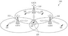
도 1은 실시예들이 적용되는 협력형 다중 셀 통신시스템을 나타낸 블록도이다.1 is a block diagram illustrating a cooperative multi-cell communication system to which embodiments are applied.
도 1의 협력형 다중 셀 통신시스템(100)은 둘 이상의 전송단이 협력하여 신호를 전송하는 다중 포인트 협력형 송수신 시스템(Coordinated multi-point transmission/reception System) 또는 협력형 다중 안테나 전송방식(Coordinated multi-antenna transmission system), 협력형 다중 셀 통신시스템(이하, "협력형 다중 셀 통신시스템" 또는 "CoMP"라 )이 있다.In the cooperative
실시예들이 적용되는 협력형 다중 셀 통신시스템(100)은 둘 이상의 전송단이 협력하여 신호를 전송하는 협력형 다중 셀 통신시스템으로, 각 전송단이 둘 이상의 전송 안테나를 구비하고 하나 이상의 전송단이 수신단으로부터 채널 정보를 수신하여 다중 안테나 전송을 수행할 수 있다.The cooperative
이 협력형 다중 셀 통신시스템(100)에서 둘 이상, 예를 들어 3개의 기지국(110, 112, 114)은 하나의 사용자 단말(120)에게 협력형 송수신을 시도할 때 동일한 시간에 동일한 주파수 자원을 할당하여 서비스를 하게 된다. 즉 동일 시간에 협력형 기지국으로 선택된 3개의 기지국들(110, 112, 114)은 동일한 주파수 자원을 사용하여 하나의 사용자 단말(120)과 데이터를 송수신할 수 있다.In this cooperative
이러한 통신방식을 사용하는 단말들은 주로 셀간 경계지역에 있어 셀의 중심지역에 있는 셀들에 비해 신호의 세기가 약한 단말들일 수 있으며, 다른 기지국과의 거리도 비교적 가까워 둘 이상의 기지국으로부터 신호를 받을 수 있는 단말들일 수도 있다. 각기 다른 크기의 셀 커버리지(cell coverage)를 가지는 기지국이 중첩적으로 배치되는 헤테로지니어스 네트워크(heterogeneous network, Het-Net)의 경우, 셀 엣지(cell edge)에 위치하지 않는 단말이라 하더라도 네트웍 구조에 의해 둘 이상의 기지국 (예를 들어 하나의 pico-cell 기지국과 하나의 macro-cell 기지국) 으로부터 신호를 수신하는 게 가능할 수 있다. 둘 이상의 기지국이 이러한 단말들에게 협력형으로 신호를 전송하므로 단말이 기존 하나의 기지국으로부터 신호를 받는 것보다 더 좋은 성능을 얻을 수 있다. 이때 두 개의 기지국들이 협력할 수도 있고 세 개 이상의 기지국들이 협력할 수 있다. 또한, 단일 사용자 다중 안테나(SU-MIMO) 방식뿐만 아니라, 다중 사용자 다중 안테나(MU-MIMO) 방식에도 이를 적용할 수 있다.Terminals using such a communication method may be terminals having weaker signal strength than cells in the center region of a cell mainly in an intercell boundary region, and are relatively close to other base stations, and thus may receive signals from two or more base stations. It may be terminals. In the case of a heterogeneous network (Het-Net) in which base stations having different cell coverages of different sizes are overlapped, even if the terminal is not located at the cell edge, the network structure It may be possible to receive signals from two or more base stations (eg one pico-cell base station and one macro-cell base station). Since two or more base stations transmit signals in a cooperative manner to these terminals, the terminal may obtain better performance than receiving signals from one base station. At this time, two base stations may cooperate or three or more base stations may cooperate. In addition, the present invention can be applied not only to a single user multiple antenna (SU-MIMO) scheme but also to a multi user multiple antenna (MU-MIMO) scheme.
협력형 다중 셀 통신시스템(100)은 음성, 패킷 데이터 등과 같은 다양한 통신 서비스를 제공하기 위해 널리 배치될 수 있다.The cooperative
본 명세서에서의 단말(120, User Equipment, UE)은 무선 통신에서의 사용자 단말을 의미하는 포괄적 개념으로서, WCDMA 및 LTE, HSPA 등에서의 UE(User Equipment)는 물론, GSM에서의 MS(Mobile Station), UT(User Terminal), SS(Subscriber Station), 무선기기(wireless device) 등을 모두 포함하는 개념으로 해석되어야 할 것이다.Terminal 120 (User Equipment, UE) in the present specification is a comprehensive concept that means a user terminal in wireless communication, WCDMA and UE (User Equipment) in LTE, HSPA, etc., as well as MS (Mobile Station) in GSM It should be interpreted as a concept that includes a user terminal (UT), a subscriber station (SS), and a wireless device.
하나의 단말(120)은 두 개 또는 그 이상의 기지국(110, 112, 114)과 동시에 연결되어 서비스를 받을 수도 있으며, 복수의 기지국(110, 112, 114)과 일정 시간을 주기로 채널상황에 따라 가장 좋은 채널을 가지는 기지국과 연결되어 서비스를 받을 수도 있다. 따라서 협력형 기지국으로 선택되는 기지국은 한 단말에 대해 임의의 주파수 밴드에 대해 좋은 채널 성능을 가지는 기지국이어야 한다.One
기지국(110, 112, 114, Base Station, BS) 또는 셀(cell)은 일반적으로 단말(120)과 통신하는 고정된 지점(fixed station)을 말하며, 노드-B(Node-B), eNB(evolved Node-B), BTS(Base Transceiver System), 액세스 포인트(Access Point) 등 다른 용어로 불릴 수 있다.A base station (110, 112, 114, base station, BS) or a cell (cell) generally refers to a fixed station (communication) a fixed station (fixed station) to communicate with the terminal 120, Node-B (Node-B), eNB (evolved) Node-B), BTS (Base Transceiver System), access point (Access Point) may be called other terms.
즉, 본 명세서에서 기지국(110, 112, 114) 또는 셀(cell)은 CDMA에서의 BSC(Base Station Controller), WCDMA의 NodeB 등이 커버하는 일부 영역을 나타내는 포괄적인 의미로 해석되어야 하며, 메가셀, 매크로셀, 마이크로셀, 피코셀, 펨토셀 등 다양한 커버리지 영역을 모두 포괄하는 의미이다.That is, in the present specification, the
본 명세서에서 기지국(110, 113, 114)과 단말(120)은 본 명세서에서 기술되는 기술 또는 기술적 사상을 구현하는데 사용되는 두 가지 송수신 주체로 포괄적인 의미로 사용되며 특정하게 지칭되는 용어 또는 단어에 의해 한정되지 않는다.In the present specification, the
무선통신 시스템에 적용되는 다중 접속 기법에는 제한이 없다. CDMA(Code Division Multiple Access), TDMA(Time Division Multiple Access), FDMA(Frequency Division Multiple Access), OFDMA(Orthogonal Frequency Division Multiple Access), OFDM-FDMA, OFDM-TDMA, OFDM-CDMA와 같은 다양한 다중 접속 기법을 사용할 수 있다.There are no restrictions on multiple access schemes applied to wireless communication systems. Various multiple access techniques such as Code Division Multiple Access (CDMA), Time Division Multiple Access (TDMA), Frequency Division Multiple Access (FDMA), Orthogonal Frequency Division Multiple Access (OFDMA), OFDM-FDMA, OFDM-TDMA, OFDM-CDMA Can be used.
본 발명의 일실시예는 GSM, WCDMA, HSPA를 거쳐 LTE 및 LTE-advanced로 진화하는 비동기 무선통신과, CDMA, CDMA-2000 및 UMB로 진화하는 동기식 무선 통신 분야의) 등의 자원할당에 적용될 수 있다. 본 발명은 특정한 무선통신 분야에 한정되거나 제한되어 해석되어서는 아니되며, 본 발명의 사상이 적용될 수 있는 모든 기술분야를 포함하는 것으로 해석되어야 할 것이다.One embodiment of the present invention can be applied to resource allocation, such as asynchronous wireless communication evolving to LTE and LTE-advanced through GSM, WCDMA, HSPA, and synchronous wireless communication evolving to CDMA, CDMA-2000 and UMB). have. The present invention should not be construed as being limited or limited to a specific wireless communication field, but should be construed as including all technical fields to which the spirit of the present invention can be applied.
특히 음영 지역 또는 전파의 수신 강도가 상대적으로 약한 셀 또는 섹터 경계 지역에 위치한 단말에 보다 높은 수신 감도를 제공하고 또한 셀 간 간섭을 줄이기 위하여 또는 보다 효과적인 무전 자원 활용을 위해 또는 하나 이상의 전송단이 협력하여 신호를 전송할 수 있다. 상기에서 전송단이라 함은 다른 기지국에 속한 전송단 일 수도 동일 기지국에 속하는 다른 셀을 담당하는 전송단 일 수도 있다.
In particular, to provide a higher reception sensitivity to a terminal located in a cell or sector boundary area where the reception strength of the radio wave region or the radio wave is relatively weak, and to reduce the interference between cells or to use the radio resources more effectively or to cooperate with one or more transmitters. Signal can be transmitted. In the above, the transmitting end may be a transmitting end belonging to another base station or a transmitting end in charge of another cell belonging to the same base station.
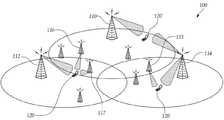
도 2는 실시예들이 적용되는 다른 협력형 다중 셀 통신시스템을 나타낸 블록도이다.2 is a block diagram illustrating another cooperative multi-cell communication system to which embodiments are applied.
도 2를 참조하면, 실시예들이 적용되는 다른 협력형 다중 셀 통신시스템(100)에서 단말(120)과 협력형 통신을 수행하는 기지국은 도 1에 도시한 매크로 기지국(110, 112, 114)일 수 있지만 하나의 매크로 기지국(110, 112, 114)의 셀 반경 내에는 위치하는 펨토 셀(Femto cell, 115), 피코 셀(Pico cell, 116), 릴레이(Relay, 117), 핫스팟(Hot spot, 118)과 같은 다양한 형태의 마이크로 또는 로컬 기지국들일 수도 있다. 도 2와 같이 다양한 형태의 기지국들로 구성된 네트워크를 헤테로지니어스 네트워크(Heterogenous network)라고 한다.2, in another cooperative
각 전송단이 둘 이상의 전송 안테나를 구비하고 MIMO 전송이 가능한 경우 협력형 다중 셀 통신시스템(100)은 매크로 기지국들(110, 112, 114) 간 협력형 통신을 수행하는 경우뿐 아니라 마이크로 기지국 또는 피코 기지국(115, 116, 117) 등 각각 다른 구동 특성을 가지는 기지국들 간에도 협력형 통신을 통해 보다 우수한 시스템 성능을 획득할 수 있다.If each transmitting end is provided with two or more transmitting antennas and MIMO transmission is possible, the cooperative
또는 빔형성 또는 프리코딩시 기존에 서비스받고 있는 기지국과의 채널상황만을 고려하여 빔형성 또는 프리코딩 값을 설정하였다면 협력형 다중 셀 통신시스템에서 기지국은 주변 기지국과의 채널 상황에 대한 추정값 또는 간섭값을 추정하여 빔형성 또는 프리코딩 값을 설정할 수가 있다.Alternatively, if beamforming or precoding values are set in consideration of only channel conditions with existing base stations during beamforming or precoding, in a cooperative multi-cell communication system, a base station estimates or interferes with channel conditions with neighboring base stations. It is possible to set the beamforming or precoding value by estimating.
도 1 및 도 2를 참조하면, 단말(120)은 각 기지국(110 내지 117)이 보내오는 참조신호들을 해석하여 각 기지국(110 내지 117)의 안테나별 채널 상황을 파악할 수가 있다. 각 채널상황을 파악한 후 그 정보를 직접 또는 간접적으로 각 기지국(120)에 피드백하게 된다. 이 정보를 피드백 받은 기지국(110 내지 117) 또는 상위계층은 좋은 채널 성능을 보이고 있는 기지국들을 선택하여 협력형 기지국 세트 또는 CoMP 세트를 형성하고 협력형 기지국 세트 또는 CoMP 세트에 포함된 기지국들은 협력형 송수신을 개시하게 된다.1 and 2, the terminal 120 analyzes reference signals transmitted from each of the
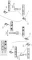
도 3은 본 발명의 일 실시예가 적용되는 헤테로지니어스 네트워크에서의 간섭을 회피하는 예를 보여주는 도면이다.3 is a diagram illustrating an example of avoiding interference in a heterogeneous network to which an embodiment of the present invention is applied.
도 3에서는 eICIC(enhanced InterCell Interference Coordination) 전송을 위한 측정 패턴(Measurement Pattern)을 매크로 기지국 및 피코 기지국을 일 실시예로 하는데, 매크로 기지국(Macro eNB)의 전송 패턴(310)과 피코 기지국(Pico eNB)의 전송 패턴(320)을 보여주고 있다. 도 3의 매크로/피코 기지국 내에는 4 종류의 사용자 단말이 존재할 수 있다. LTE Rel-8, 9를 따르는 제 1 유형의 사용자 단말이 있으며, 이들 제 1 유형의 사용자 단말은 다시 매크로 기지국에 결합하였는지 또는 피코 기지국에 결합하였는지에 따라 제 1 유형 매크로 사용자 단말(Legacy MUE)과 제 1 유형 피코 사용자 단말(Legacy PUE)로 구분하고자 한다. 상기 LTE Rel-8, 9은 eICIC 방식의 동작이 지원되지 않는다.In FIG. 3, a measurement pattern for enhanced InterCell Interference Coordination (eICIC) transmission includes a macro base station and a pico base station, and a
한편, LTE-Advanced Rel-10을 따르는 제 2 유형의 사용자 단말이 있으며, 이들 제 2 유형의 사용자 단말은 다시 매크로 기지국에 결합하였는지 또는 피코 기지국에 결합하였는지에 따라 제 2 유형 매크로 사용자 단말(Rel-10 MUE)과 제 2 유형 피코 사용자 단말(Rel-10 PUE)로 구분하고자 한다. 상기 제 1, 2 유형으로 나누는 것은 하나의 무선 시스템 내에 구현 또는 적용되는 통신 시스템을 달리하는 사용자 단말을 구분 짓기 위한 것이며, 이러한 구분이 반드시 LTE, LTE-Advanced, 또는 Rel-8, 9 및 Rel-10에 한정되는 것은 아니다.On the other hand, there is a second type of user terminal that conforms to LTE-Advanced Rel-10, and the second type of user terminal depends on whether it is coupled to the macro base station or the pico base station again. MUE) and a second type pico user terminal (Rel-10 PUE). The dividing into the first and second types is for distinguishing user terminals that differ in a communication system implemented or applied in one wireless system, and this division is necessarily LTE, LTE-Advanced, or Rel-8, 9 and Rel-. It is not limited to ten.
매크로 기지국의 전송 패턴(310)은 제 1 유형의 매크로 사용자 단말에 할당된 주파수 대역(311)과 제 2 유형의 매크로 사용자 단말에 할당된 주파수 대역으로 구분되어 있다. 따라서, 제 1 유형의 매크로 사용자 단말은 제 2 유형의 매크로 사용자 단말이 송수신하는 신호와의 간섭을 회피할 수 있다.The
마찬가지로, 피코 기지국의 전송 패턴(320)은 제 1 유형의 피코 사용자 단말(존재할 경우)에 할당된 주파수 대역(321)과 제 2 유형의 피코 사용자 단말에 할당된 주파수 대역으로 구분되어 있다. 따라서, 제 2 유형의 피코 사용자 단말은 제 2 유형의 피코 사용자 단말이 송수신하는 신호와의 간섭을 회피할 수 있다.Similarly, the
310, 320을 살펴보면, 제 1 유형의 매크로 사용자 단말과 피코 사용자 단말은 주파수(frequency) 대역으로 구분됨을 알 수 있다. 한편, 제 2 유형의 매크로 사용자 단말과 피코 사용자 단말은 시간(time) 대역으로 구분됨을 알 수 있다. 따라서 각각의 매크로/피코 기지국과 데이터를 송수신할 경우, 데이터를 시간상으로 달리 송수신할 수 있도록 하여 셀 간의 간섭을 줄일 수 있다.Referring to 310 and 320, it can be seen that the first type of macro user terminal and the pico user terminal are divided into frequency bands. On the other hand, it can be seen that the second type of macro user terminal and the pico user terminal are divided into time bands. Therefore, when transmitting and receiving data with each macro / pico base station, data can be transmitted and received differently in time, thereby reducing interference between cells.
보다 상세히 설명하면, 기지국 또는 셀(매크로-매크로, 또는 매크로-피코 등)은 자신들이 감당해야 할 로드(load) 및 영역을 공유하게 된다. 매크로-매크로의 영우에는 일부를 공유하며, 매크로-피코의 경우에는 피코의 전체 영역을 매크로와 공유하는 것이 일반적이다. 보다 상세히 설명하면 다음과 같다. eICIC 적용되지 않는 시스템의 경우 Macro와 Pico가 대역을 구분하여 사용하여야 하는 반면, eICIC 적용 시에는 Macro와 Pico가 동일 대역을 시간축에서 구분하여 사용할 수 있다. 따라서 Rel-10 단말에 대해서는 Macro와 Pico가 각 cell의 load에 따라 각 기지국이 사용랑 무선 용량을 적응적으로 분할하여 사용 가능 한 반면, Rel-8,9 단말과 Rel-10 단말 간에는 상기와 같은 작용이 불가능하다. CoMP 동작하는 Rel-11 단말이 상기 시스템에 동일 방식으로 적용 될 경우, 각 기지국 Macro/Pico은 우선적으로 Rel-8/9 단말이 사용 할 대역, Rel-10 단말이 사용 할 대역, Rel-11 CoMP 단말이 사용 할 대역을 분할 후 Rel-10 또는 Rel-11 단말이 사용하는 대역 내에서 Macro-Pico cell load에 따른 무선 자원 용량 시간축 할당을 수행하여야 한다. 상기 방식에 보다 자유로운 무선 용량 활용 및 할당을 위해, 본 발명의 일 실시예에서는 Rel-10 eICIC 단말과 Rel-11 CoMP 단말이 동일 방식으로 시간축 자원 할당 방식을 사용하도록 하여 Rel-10 단말 및 Rel-11 CoMP 단말이 동일 대역을 사용할 수 있도록 한다. 즉, 다양한 유형의 사용자 단말이 공존하는 무선 네트워크 시스템에서 시간 축 무선 자원 공유 및 분할을 패턴을 통해 수행할 수 있다. 이 경우, 기지국 또는 셀의 전송량 등을 고려하여 전송 패턴(pattern)을 결정할 수 있다. 그리고 이러한 패턴을 X2 인터페이스(interface)를 통해 기지국 간 또는 셀간에 공유하며, 상기 패턴 내에서 각 기지국 또는 셀 별 스케쥴링(scheduling)을 실시할 수 있다. 310, 320은 매크로-피코 간의 전송 패턴을 보여주는 예이다. 310, 320에는 각각의 기지국(매크로, 피코)에서 전송 패턴에서 데이터가 송수신되지 않는 영역들이 있는데 이들을 ABS(Almost Blank Subframe)이라고 한다. 이는 간섭을 줄이기 위하여 해당 서브프레임에서 전송 파워를 0에 가깝게 하는 것을 의미한다. 이는 해당 서브프레임의 패턴이 적용되는 대역에 한하여 신호 전송을 수행하지 않음을 의미한다.In more detail, the base station or cell (macro-macro, or macro-pico, etc.) will share the load and area they must bear. Part of the macro-macro's domain is shared, and in the case of macro-pico, it is common to share the entire area of the pico with the macro. More detailed description is as follows. In case of non-ICIC system, macro and pico should be used separately in the band, whereas in eICIC, macro and pico can use the same band in the time axis. Therefore, for the Rel-10 terminal, each base station can adaptively divide the use and the radio capacity according to the load of each cell, whereas the macros and pico can be used as described above between the Rel-8, 9 and Rel-10 terminals. It is impossible to work. When the Rel-11 UE operating in CoMP is applied to the system in the same manner, each base station Macro / Pico is preferentially used by the Rel-8 / 9 terminal, the band used by the Rel-10 terminal, and the Rel-11 CoMP. After dividing the band to be used by the terminal, the radio resource capacity time base allocation according to the macro-pico cell load must be performed in the band used by the Rel-10 or Rel-11 terminal. In order to use and allocate radio capacity more freely to the above scheme, in an embodiment of the present invention, the Rel-10 eICIC terminal and the Rel-11 CoMP terminal use the time-base resource allocation scheme in the same manner so that the Rel-10 terminal and the Rel- 11 CoMP terminal can use the same band. That is, in a wireless network system in which various types of user terminals coexist, time axis radio resource sharing and partitioning may be performed through a pattern. In this case, the transmission pattern may be determined in consideration of the transmission amount of the base station or the cell. The pattern may be shared between base stations or cells through an X2 interface, and scheduling may be performed for each base station or cell within the pattern. 310 and 320 show examples of a transmission pattern between macro and pico. In 310 and 320, there are regions in which data is not transmitted or received in a transmission pattern at each base station (macro, pico), which is called ABS (Almost Blank Subframe). This means that the transmission power is close to zero in the corresponding subframe in order to reduce interference. This means that the signal transmission is not performed only in the band to which the pattern of the subframe is applied.
한편, 각 셀이 사용하는 패턴에 따라 각 단말이 링크 또는 채널 측정을 수행할 서브프레임의 위치가 결정된다. 각 기지국은 각 단말에 채널 또는 링크 측정을 위한 측정 패턴(measurement pattern)을 통보하게 된다. 측정 패턴이란 채널 또는 링크의 상태를 측정을 위해 참조 신호(Reference Signal, RS)를 측정하여야 하는 서브프레임의 위치 정보를 포함하는 것을 의미한다. 각 기지국은 통보 받은 측정 패턴에 따라 RS로부터 채널 상태 또는 링크 상태를 측정하고 이를 기지국에 전달한다.Meanwhile, the position of a subframe in which each UE performs link or channel measurement is determined according to a pattern used by each cell. Each base station notifies each terminal of a measurement pattern for channel or link measurement. The measurement pattern means that position information of a subframe in which a reference signal (RS) should be measured to measure a state of a channel or a link. Each base station measures the channel state or link state from the RS according to the measured measurement pattern and transmits it to the base station.
정리하면, 도 3에서는 매크로와 피코 셀이 공존하는 헤테로지니어스 네트워크(Heterogeneous network, Het-Net)에서, 제 1 유형의 단말(Rel-9 이전 단말)이 기지국에 접속을 요구하는 경우, 매크로와 피코 셀간 간섭 제어를 위해 매크로에 접속된 단말과 피코에 접속된 단말은 311, 312와 같이 각기 다른 대역을 사용하여 기지국에 접속된다. 매크로에 접속된 제 1 유형의 단말(Rel-9 이전 단말)과 피코에 접속된 제 1 유형의 단말(Rel-9 이전 단말)이 사용 할 대역은 각 기지국이 임의로 결정 할 수 없으며 기지국 간 합의를 통해 세미 스태틱(semi-static)하게 변화 하거나 또는 고정된다.In summary, in FIG. 3, in a heterogeneous network (Het-Net) in which a macro and a pico cell coexist, when a first type of terminal (pre-Rel-9 terminal) requests access to a base station, the macro and pico For inter-cell interference control, a terminal connected to a macro and a terminal connected to a pico are connected to a base station using different bands such as 311 and 312. The base bands used by the first type terminal (pre-Rel-9 terminal) connected to the macro and the first type terminal (pre-Rel-9 terminal) connected to the pico cannot be arbitrarily determined by each base station, It is semi-statically changed or fixed.
제 2 유형의 단말(Rel-10 단말)은 제 1 유형의 매크로 단말 및 제 1 유형의 피코 단말과는 다른 대역을 사용하여 기지국에 접속한다. 또한 제 2 유형의 단말에 신호 및 정보를 전송하는 매크로 기지국과 피코 기지국간에는 312, 322와 같이 시 분할(time division) 방식을 사용하여 매크로-피코 셀간 간섭을 피할 수 있다. 각 기지국이 사용하는 ABS 패턴에 대한 정보는 각 단말에 전달하지 않아도 되는 반면, 전송 패턴에 따른 측정 패턴은 해당 단말에 전달되어야 한다. 측정 패턴을 전달하는 예는 도 4에 도시되어 있다.The second type of terminal (Rel-10 terminal) connects to the base station using a band different from the first type of macro terminal and the first type of pico terminal. In addition, between the macro base station and the pico base station that transmits signals and information to the second type of terminal, a time division scheme such as 312 and 322 may be used to avoid interference between macro-pico cells. While information on the ABS pattern used by each base station does not have to be transmitted to each terminal, the measurement pattern according to the transmission pattern should be delivered to the corresponding terminal. An example of delivering a measurement pattern is shown in FIG. 4.
도 4는 본 발명의 일 실시예가 적용되는 헤테로지니어스 네트워크에서의 간섭을 회피하도록 측정 패턴을 송신하는 과정을 보여주는 도면이다. 도 4에서는 매크로 기지국과 피코 기지국 간에 네트워크 정보를 공유하여 ABS 패턴을 결정하고 이에 따라 각각의 사용자 단말들에게 측정 패턴을 송신하는 과정을 보여주고 있다. 보다 상세히 살펴보면 다음과 같다. 도 4의 과정은 eICIC 구현을 위한 시그널링의 예를 보여준다.4 is a diagram illustrating a process of transmitting a measurement pattern to avoid interference in a heterogeneous network to which an embodiment of the present invention is applied. 4 shows a process of determining an ABS pattern by sharing network information between a macro base station and a pico base station and transmitting a measurement pattern to each user terminal accordingly. Looking in more detail as follows. 4 shows an example of signaling for an eICIC implementation.
매크로 기지국(410)과 피코 기지국(420)는 네트워크 정보를 공유한다(S430). 네트워크 정보의 공유 과정이란 셀의 트래픽(traffic load)이 어떠한가에 따라 각각 필요한 네트워크 자원에 대한 정보를 공유하는 것을 일 실시예로 한다. 즉, 양 기지국은 X2 인터페이스를 통해 통신 상황에 대한 정보를 공유하며 상기 정보 공유에 의해 각 기지국이 신호를 전송할 수 있는 구간을 미리 결정한다. 상기 과정에서 각각의 기지국들은 전송 과정에서 데이터의 충돌이 일어나지 않도록 데이터 및 시그널링(signaling)을 전송할 구간을 결정하고 이에 대한 정보를 기지국 간에 공유한다. 여기에서 결정된 패턴을 ABS 패턴 또는 서브프레임 패턴 등으로 지칭할 수 있다. 도 4에 도시된 바와 같이 각각의 기지국은 ABS 패턴을 결정한다(S431, S432). 그리고, 앞서 살펴본 그리고 해당 ABS 패턴을 X2 인터페이스를 이용하여 공유하게 된다(S440). 따라서, eICIC 서브프레임 패턴과 상기 패턴에 대한 정보를 공유하게 된다. 이 때, X2 인터페이스를 이용하여 공유하게 되는 정보는 기지국 간에 공유되며, 단말에 통보되지는 않는다.The
그리고 공유한 ABS 패턴에 따라 자신의 셀 들에 존재하는 사용자 단말들이 측정 패턴을 송신할 수 있도록 시그널링할 수 있다(S441, S442). 이후 앞서 결정된 각 기지국이 자신이 신호를 전송 할 수 있는 서브프레임들이 결정된 후, 상기 전송 패턴에 적합한 측정 패턴들을 결정하고 상기 측정 패턴들을 접속된 단말들에 송부하게 된다. 즉, ABS 패턴에 따른 스케쥴링 결과에 따라 생성된 측정 패턴을 사용자 단말에 송신하게 된다(S451, S452). 이러한 측정 패턴은 채널 및 링크 측정을 위한 패턴으로, 이러한 패턴의 일 실시예로는 i) 서빙 셀의 링크 연결 상태를 측정하기 위한 패턴, ii) 서빙 셀의 채널 상태를 측정하기 위한 패턴, iii) 인접 셀(핸드오버 대상 셀)의 링크 상태를 측정하기 위한 패턴, 및 iv) 인접 셀의 채널 상태를 측정하기 위한 패턴 등이 될 수 있다. 인접 셀에 대한 iii) 및 iv)는 하나의 패턴으로 표현할 수 있다.In operation S441 and S442, user terminals existing in their cells may transmit a measurement pattern according to the shared ABS pattern. Thereafter, after each of the base stations determined above have determined subframes capable of transmitting signals, the base stations determine the measurement patterns suitable for the transmission pattern and transmit the measurement patterns to the connected terminals. That is, the measurement pattern generated according to the scheduling result according to the ABS pattern is transmitted to the user terminal (S451, S452). This measurement pattern is a pattern for channel and link measurement, in one embodiment of the pattern i) a pattern for measuring the link connection state of the serving cell, ii) a pattern for measuring the channel state of the serving cell, iii) A pattern for measuring a link state of an adjacent cell (handover target cell), and iv) a pattern for measuring a channel state of an adjacent cell. Iii) and iv) for neighboring cells can be expressed in one pattern.
측정 패턴을 통보하는 이유는 도 3에 명시된 패턴(312, 322)이 eICIC에 사용될 경우, 피코 기지국에 접속된 단말은 1, 2번째 subframe에서 신호를 수신 할 수 없으며, 상기 서브프레임에서는 매크로 기지국의 신호에 의한 간섭만을 수신하게 된다. 또한, 3. 4번째 서브프레임에서는 매크로 기지국에 의한 간섭 없이 피코 기지국의 신호를 수신 가능하다. 상기 서브프레임 패턴에 의해 피코 기지국이 제어하는 셀에 접속된 단말은 매크로 기지국에 의한 간섭 없이 통신이 가능하나, 단말은 각 기지국이 어느 서브프레임에서 신호를 전송하는 지에 대한 직접적인 정보 (ABS pattern에 대한 정보)를 취득하지 못하므로, 상기 피코 기지국에 접속된 단말이 첫 번째 서브프레임에서 채널 측정을 할 경우 대단히 강한 간섭이 존재함을 기지국에 보고하게 된다. 따라서, eICIC 동작 시 각 기지국은 단말에게 어느 서브프레임에서 채널 상태 및 링크 측정을 수행해야 할 지를 알려주는 것이 필요하며, 측정 패턴은 이에 대한 정보를 의미한다.The reason for notifying the measurement pattern is that when the
도 4에서는 앞서 살펴본 제 2 유형의 사용자 단말(Rel-10 적용)들인 매크로 사용자 단말(411) 및 피코 사용자 단말(421)은 S451, S452 과정에서 자신이 결합한 기지국들로부터 측정 패턴을 수신하게 되며, 해당 패턴에 따라 서빙 셀 또는 인접 셀의 링크 연결 상태와 채널 상태를 측정할 수 있다.
In FIG. 4, the
도 5는 본 발명의 일 실시예가 적용되는 eICIC 상황에서 ABS 패턴에 따른 기지국-단말 간의 전송 예를 보여주는 도면이다. 도 3에서 제 2 유형의 사용자 단말들은 서브프레임을 나누어 할당하였는데, 즉, 매크로 사용자 단말과 피코 사용자 단말에 서로 상이한 서브프레임을 할당하였다. 제 2 유형의 매크로 사용자 단말은 312로 지시되는 영역을 사용하고, 제 2 유형의 피코 사용자 단말은 322로 지시되는 영역을 사용한다. 이는 셀간 간섭이 큰 경우에는 동일한 주파수 대역을 사용하는 사용자 단말들 간에 구분을 위한 것이며, 주파수 대역이 상이한 경우, 예를 들어 제 1 영역의 사용자 단말은 이러한 구분에 적용되지 않는다.5 is a diagram illustrating an example of transmission between a base station and a terminal according to an ABS pattern in an eICIC situation to which an embodiment of the present invention is applied. In FIG. 3, the second type of user terminals are divided into subframes, that is, different subframes are allocated to the macro user terminal and the pico user terminal. The second type of macro user terminal uses an area indicated by 312 and the second type of pico user terminal uses an area indicated by 322. This is for distinguishing between user terminals using the same frequency band when the inter-cell interference is large. For example, when the frequency bands are different, for example, the user terminal in the first region is not applied to such division.
따라서 도 5의 매크로 기지국(510)의 ABS 패턴에 따른 전송 예는 512, 514 사용자 단말에 대해 515 패턴에 따라 데이터를 송수신할 수 있다. 한편 피코 기지국(520, 530)의 경우 522, 524, 532의 사용자 단말에 대하여 525 패턴에 따라 데이터를 송수신할 수 있다. 도 5에서 매크로 기지국이 송신하는 신호와 피코 기지국이 송신하는 신호는 ABS 패턴에 따라 시간을 기준으로 어느 한 셀에서 신호를 송신하는 것이므로 셀 간의 간섭을 회피할 수 있다.Accordingly, in the transmission example according to the ABS pattern of the
534와 같이 매크로 기지국의 신호를 받지 않는 사용자 단말인 경우에는 525의 패턴이 적용되지 않고 전체 서브프레임을 사용할 수 있다.
In the case of a user terminal that does not receive a signal from the macro base station, such as 534, the entire subframe may be used without applying the pattern of 525.
도 3, 4, 5에서 살펴본 바와 같이, 다양한 유형의 사용자 단말이 헤테로지니어스 네트워크에 속하게 되는 경우, 셀 간의 간섭을 관리하는 것이 필요하다. 앞서 제 2 유형의 단말(Rel-10)들 간에는 ABS 패턴을 사용한 시분할 셀간 간섭 관리(time division inter-cell-interference management)가 가능하나 제 1 유형의 단말(REl-8, 9)은 상기 방식의 사용이 불가능하다. 따라서, 제 1 유형(Rel-8, 9) 및 제 2 유형(Rel-10) 단말 간에는 도 3에서 살펴본 바와 같이 주파수 대역을 구분하여 피코-매크로 셀 간 접속을 구분할 수 있다. 이러한 방식은 사용할 수 있는 전체 시간-주파수 대역을 각각의 통신 시스템이 일부만 사용하게 되므로, 주파수 효율 및 스케쥴링 효율을 감소시킨다.3, 4 and 5, when various types of user terminals belong to a heterogeneous network, it is necessary to manage interference between cells. The time division inter-cell-interference management using the ABS pattern is possible between the second type of terminals Rel-10, but the first type of terminals REl-8 and 9 are the same. impossible to use. Therefore, as shown in FIG. 3, the first type Rel-8 and 9 and the second type Rel-10 terminal may distinguish the connection between the pico-macro cells by separating the frequency band. This approach reduces the frequency efficiency and scheduling efficiency since each communication system uses only a portion of the total available time-frequency band.
두 가지의 유형으로 나뉘어지는 사용자 단말이 공존할 경우, 즉, 셀간 간섭을 피하도록 하는 eICIC 방식으로 동작하는 사용자 단말이 공존할 경우, 전송 방식의 차이로 인하여 통신 시스템의 통신 효율 및 용량이 감소 할 수 있게 되므로, 새로운 유형인 제 3 유형의 사용자 단말이 추가될 경우 이러한 통신 효율이 낮아질 가능성이 높아지므로 이를 해결하는 과정이 필요하다. 예를 들어, CoMP 방식으로 통신을 하는 Rel-11 단말을 제 3 유형의 단말의 일 실시예라고 할 경우, eICIC로 동작하는 전송 방식의 차이에 의하여 시스템의 효율이 감소하는 것을 회피하도록 시스템을 설계하는 것이 필요하다. 이하, 새로운 유형의 사용자 단말의 실시예로 CoMP 방식으로 동작하는 Rel-11 단말의 신호 전송이 eICIC 방식으로 동작하는 제 2 유형의 사용자 단말(예를 들어 REl-10)에 미치는 영향을 최소화 하는 전송 방식에 대해 살펴보고자 한다.
When user terminals divided into two types coexist, that is, when user terminals operating in an eICIC scheme coexist to avoid inter-cell interference, communication efficiency and capacity of a communication system may decrease due to differences in transmission methods. In this case, when a new type of the third type of user terminal is added, the possibility of such communication efficiency is lowered, and thus a process for solving the problem is required. For example, if the Rel-11 terminal communicating with the CoMP scheme is an embodiment of the third type of terminal, the system is designed to avoid the reduction of the efficiency of the system due to the difference in the transmission scheme operating with the eICIC. It is necessary to do Hereinafter, as an embodiment of a new type of user terminal, a transmission for minimizing the effect of the signal transmission of the Rel-11 terminal operating in the CoMP method on the second type user terminal (for example, REl-10) operating in the eICIC method Let's look at how.
도 6은 본 명세서의 일 실시예에 의한 세 가지 유형의 사용자 단말이 공존할 경우 자원 할당의 예를 보여주는 도면이다. 앞서 도 3에서 eICIC를 위한 ABS 패턴이 결정된 것과 같이 CoMP 모드로 동작할 수 있는 제 3 유형의 사용자 단말을 위한 서브프레임을 결정할 수 있다. 이때, CoMP로 동작 가능하도록 선정된 서브프레임은 eICIC에서 매크로 기지국이 신호를 전송 할 수 있도록 선정된 서브프레임(612)의 부분집합(subset)이 되도록 선택할 수 있다. 보다 상세히 살펴보면 다음과 같다.6 is a diagram illustrating an example of resource allocation when three types of user terminals coexist according to one embodiment of the present specification. As shown in FIG. 3, the ABS pattern for the eICIC may determine a subframe for the third type of user terminal that may operate in the CoMP mode. In this case, the subframe selected to be operated by CoMP may be selected to be a subset of the selected
제 1 유형(Legacy, Rel-9 이전)의 사용자 단말과의 데이터 송신에서는 매크로 기지국의 경우 611과 같이, 피코 기지국인 경우 621과 같이 주파수 대역을 구분하여 송수신한다.In data transmission with a user terminal of a first type (Legacy, before Rel-9), a frequency band is divided and transmitted as shown in 611 for a macro base station and 621 for a pico base station.
한편 제 2 유형(Rel-10)의 사용자 단말과의 데이터 송신에서는 매크로 기지국의 경우 612와 같이, 피코 기지국인 경우 622와 같이 시간 대역을 구분하여 송수신한다. 이 경우 제 2 유형의 매크로 사용자 단말과 피코 사용자 단말은 서로 시간을 달리하여 데이터를 송수신하게 되므로 간섭이 발생하지 않게 된다.Meanwhile, in the data transmission with the second type Rel-10 user terminal, time bands are divided and transmitted as shown in case of the
한편, 매크로 기지국이 제 2 유형의 사용자 단말에게 송신하게 되는 영역(612)과 같거나 혹은 그의 부분 집합이 되는 영역에서 제 3 유형(CoMP) 사용자 단말에 데이터를 송수신하도록 설정할 수 있다. CoMP 방식의 송수신은 매크로 기지국과 피코 기지국으로부터 신호를 송수신하는 방식이므로, 피코 기지국이 송신하는 서브프레임 패턴에서도 상기 영역(612)에 해당하는 부분에서 피코 기지국이 신호를 송수신하게 된다.Meanwhile, the macro base station may be configured to transmit and receive data to and from the third type (CoMP) user terminal in an area that is the same as or a subset of the
따라서 CoMP 전송을 수행하도록 매크로 기지국 및 피코 기지국이 전송하는 서브프레임 패턴은 아래의 세 가지 패턴을 포함한다.
Therefore, the subframe pattern transmitted by the macro base station and the pico base station to perform CoMP transmission includes the following three patterns.
i) 매크로 기지국만 신호를 전송하는 서브프레임(611 및 612)i) subframes 611 and 612 in which only the macro base station transmits signals;
ii)피코 기지국만 신호를 전송하는 서브프레임(621및 622)ii) subframes 621 and 622 in which only the pico base station transmits a signal;
iii) MeNB와 PeNB가 모두 신호를 전송하는 서브프레임(622의 부분집합이 되는 서브프레임)iii) subframe in which both MeNB and PeNB transmit signals (subframe that is a subset of 622)
상기 실시예에서, 첫 번째 서브프레임은 CoMP 전송 서브프레임의 구성 방식에 따라 존재하지 않을 수도 있다.In the above embodiment, the first subframe may not exist according to the configuration method of the CoMP transmission subframe.
상기와 같은 방식으로 시분할 방식으로 제한된 영역(subframe)에서 CoMP 구동 시, eICIC 동작하는 제 2 유형 단말(Rel-10)에 매크로-피코 셀간 간섭을 발생시키지 않고 CoMP을 구현 할 수 있으며, 따라서 별도로 주파수 대역폭을 분할하지 않고도 제 2 유형의 단말 및 제 3 유형의 단말, 또는 그 이상의 유형의 단말을 동일 대역을 통해 접속 허가할 수 있다.
When CoMP is driven in a limited time (subframe) in a time division manner as described above, CoMP can be implemented without causing interference between macro-pico cells in the second type terminal Rel-10 operating with eICIC, and thus, separately frequency. The second type of terminal and the third type of terminal or more types of terminals may be allowed to be connected through the same band without dividing the bandwidth.
도 7은 본 발명의 일 실시예가 적용되는 eICIC 방식으로 동작하는 사용자 단말과 CoMP 방식으로 동작하는 사용자 단말 간의 시그널링을 나타내는 도면이다.7 is a diagram illustrating signaling between a user terminal operating in an eICIC scheme and a user terminal operating in a CoMP scheme to which an embodiment of the present invention is applied.
CoMP 방식의 동작 또한 사전에 미리 합의된 서브프레임 패턴에 따라 정보 전송이 수행되며, 기지국은 CoMP로 동작하는 서브프레임의 위치를 고려하여 측정 패턴을 설계하여 각 단말에 통보한다. 간섭을 회피하도록 측정 패턴을 송신하는 과정을 보다 상세히 살펴보면 다음과 같다.In the operation of the CoMP scheme, information transmission is performed according to a previously agreed subframe pattern, and the base station designes a measurement pattern in consideration of the position of the subframe operating in CoMP and notifies each terminal. Looking at the process of transmitting the measurement pattern to avoid interference in more detail as follows.
매크로 기지국(710)과 피코 기지국(720)은 네트워크 정보를 공유한다(S730). 그리고 각 기지국은 ABS 패턴을 결정한다(S731, S732). 그리고 결정한 ABS 패턴을 공유하는데, 일 실시예로 X2 인터페이스를 이용하여 공유할 수 있다(S740). 이는 앞서 도 4에서 살펴본 바와 같다.The
피코 기지국(720)은 제 2 유형의 사용자 단말(722)와 제 3 유형의 사용자 단말(723)에게 송신할 측정 패턴을 결정하기 위하여, S732에서 결정된 ABS 패턴에 따라 스케쥴링을 수행한다(S742). 그리고 제 3 유형, 즉 CoMP 스케쥴링 정보를 매크로 기지국(710)에 송신한다(S750). CoMP 스케쥴링이 완료된 피코 기지국은 제 2 유형 사용자 단말(722)과 제 3 유형의 사용자 단말(723)에게 eICIC 측정 패턴을 송신한다(S755, S756). eICIC 측정 패턴은 피코 기지국 내의 사용자 단말이 매크로 기지국이 송수신하는 신호와 간섭하지 않도록 eICIC로 동작을 가능하게 하는 측정 패턴이다. 또한, 제 3 유형, 즉 CoMP 방식으로 동작하는 사용자 단말(723)에게 CoMP 측정 패턴을 송신한다(S757). CoMP 측정 패턴은 앞서 살펴본 매크로 기지국이 송신하는 서브프레임의 서브셋을 구성하는 CoMP 송수신 패턴에서 산출되는 것이다.The
한편, 매크로 기지국(710)은 피코 기지국(720)이 생성한 CoMP 스케쥴링 정보(S750) 및 ABS 패턴에 따라 제 3 유형의 사용자 단말에 대한 스케쥴링을 수행한다(S751). 스케쥴링이 완료된 매크로 기지국(710)은 제 2 유형 사용자 단말(712)과 제 3 유형의 사용자 단말(713)에게 eICIC 측정 패턴을 송신한다(S761, S762). eICIC 측정 패턴은 매크로 기지국 내의 사용자 단말이 피코 기지국이 송수신하는 신호와 간섭하지 않도록 eICIC로 동작을 가능하게 하는 측정 패턴이다. 또한, 제 3 유형, 즉 CoMP 방식으로 동작하는 사용자 단말(713)에게 CoMP 측정 패턴을 송신한다(S765). CoMP 측정 패턴은 앞서 살펴본 매크로 기지국이 송신하는 서브프레임의 서브셋을 구성하는 CoMP 송수신 패턴에서 산출되는 것이다.
Meanwhile, the
도 8은 본 명세서의 일 실시예가 적용되는 CoMP 및 eICIC 상황에서 ABS 패턴에 따른 기지국-단말 간의 전송 예를 보여주는 도면이다. 도 6의 서브프레임 할당 패턴에 따라 구현된 예이다.8 is a diagram illustrating an example of transmission between a base station and a terminal according to an ABS pattern in a CoMP and eICIC situation to which an embodiment of the present specification is applied. This is an example implemented according to the subframe allocation pattern of FIG. 6.
매크로 기지국(810)과 송수신되는 신호는 815 또는 816과 같다. 815는 앞서 살펴본 제 2 유형의 단말(Rel-10이 적용)이며 eICIC 방식으로 송신하는 사용자 단말(812, 814)과 송수신하는 패턴이다. 816은 제 3 유형의 사용자 단말, 즉, CoMP 방식으로 동작하는 사용자 단말(822, 832)에 매크로 기지국(810)이 신호를 송신하는 패턴이다. 816 패턴이 적용된 신호 송수신은 891, 892를 통하여 확인할 수 있다.The signal transmitted and received with the
한편, 피코 기지국(820, 830)과 송수신되는 신호는 825, 826, 827과 같다. 825는 앞서 살펴본 제 2 유형의 단말(Rel-10이 적용)이며 eICIC 방식으로 송신하는 사용자 단말(824)과 송수신하는 패턴이다. 827은 앞서 살펴본 바와 같이 매크로 기지국의 신호에 간섭되지 않으며 전체 서브프레임을 사용하는 사용자 단말(834)의 신호 송수신 패턴이다. 826은 제 3 유형의 사용자 단말, 즉, CoMP 방식으로 동작하는 사용자 단말(822, 832)에 피코 기지국(820, 830)이 신호를 송신하는 패턴이다. 826 패턴이 적용된 신호 송수신은 895, 896을 통하여 확인할 수 있다.On the other hand, the signals transmitted and received with the pico base station (820, 830) are the same as 825, 826, 827. 825 is a second type of terminal (Rel-10 applied) described above and is a pattern for transmitting and receiving with the
도 5 내지 8의 실시예에서 살펴본 바와 같이, CoMP 전송을 가능하게 하면서, 동시에 다른 유형(예를 들어 eCICI)으로 동작하는 시스템과 상호 호환이 가능하도록, 다른 유형의 사용자 단말을 위한 매크로 기지국이 신호를 전송하도록 선정된 패턴을 기반으로 하여 CoMP 전송을 위한 서브프레임 영역을 설정할 수 있다. 본 명세서에서의 CoMP는 매크로 기지국과 피코 기지국이 동시에 신호를 전송하거나(joint beam forming) 또는 어느 하나의 기지국이 신호를 전송하도록(coordinated scheduling) 매크로 또는 피코 기지국 중 하나의 기지국이 임의로 선정되어 단말에 신호를 전송하는 기법 등에 모두 적용 가능하다.As shown in the embodiments of FIGS. 5 to 8, the macro base station for the other type of user terminal is signaled to enable CoMP transmission while simultaneously being compatible with systems operating with other types (eg eCICI). A subframe region for CoMP transmission may be set based on a pattern selected to transmit. In the present specification, CoMP refers to either a macro base station and a pico base station at the same time (joint beam forming) or any one of the base station of the macro or pico base station is arbitrarily selected to transmit a signal (coordinated scheduling) to the terminal It can be applied to all methods of transmitting signals.
즉, CoMP 전송을 시간축으로 제한을 두되, 이러한 제한이 전송 효율을 높이고 간섭을 줄일 수 있도록 eICIC의 매크로 전송 패턴의 서브셋이 CoMP 전송 서브프레임이 되도록 한다. 따라서 CoMP로 동작하게 되는 사용자 단말에게 제공하는 측정 패턴은 상기 CoMP 전송 서브프레임을 기준으로 생성되며, 측정 패턴에 식별되는 서브프레임은 CoMP 전송 서브프레임과 같거나 혹은 그 일부가 될 수 있다.
In other words, CoMP transmission is limited to the time base, but this restriction allows a subset of the macro transmission pattern of the eICIC to be a CoMP transmission subframe so as to increase transmission efficiency and reduce interference. Accordingly, the measurement pattern provided to the user terminal operating with CoMP is generated based on the CoMP transmission subframe, and the subframe identified in the measurement pattern may be the same as or part of the CoMP transmission subframe.
도 9는 본 명세서의 일 실시예에 의해 생성된 CoMP 전송을 위한 측정 패턴을 사용자 단말이 수신하여 채널 및 링크를 측정하는 과정을 보여주는 도면이다. 본 명세서의 일 실시예에 의하여 피코 기지국에 결합한 사용자 단말이 매크로 기지국에서 제공하는 참조 신호(RS)와 피코 기지국에서 제공하는 참조 신호에 대하여 측정 패턴을 이용하여 측정을 수행하는 과정을 보여주는 도면이다. 도 9에서는 측정 패턴의 일 실시예로 CSI(Channel Status Information) 측정 패턴을 이용하는 예를 보여주고 있다. 도 9에서는 도 8의 CoMP(제 3 유형)의 전송 서브프레임 및 제 2 유형(Rel-10, eICIC)의 전송 서브 프레임을 기준으로 설명하고자 한다. 각각의 유형에 대한 측정 패턴에 식별되는 서브프레임은 해당 유형의 전송 서브프레임과 같거나 혹은 그 일부가 될 수 있으나, 설명의 편의를 위하여 도 9에서는 측정 패턴에 식별되는 서브프레임과 전송 서브 프레임은 같은 것으로 가정한다. 물론, 측정 패턴은 전송 서브 프레임의 일부만으로 설정하여 사용자 단말에 제공될 수 있다.9 is a diagram illustrating a process of measuring a channel and a link by a user terminal receiving a measurement pattern for CoMP transmission generated by an embodiment of the present specification. According to an embodiment of the present disclosure, a user terminal coupled to a pico base station shows a process of performing measurement using a measurement pattern on a reference signal RS provided by a macro base station and a reference signal provided by a pico base station. 9 illustrates an example of using a channel status information (CSI) measurement pattern as an embodiment of the measurement pattern. FIG. 9 will be described based on the transmission subframe of CoMP (third type) and the transmission subframe of the second type (Rel-10, eICIC) of FIG. 8. The subframe identified in the measurement pattern for each type may be the same as or part of the transmission subframe of the type. For convenience of description, the subframe and the transmission subframe identified in the measurement pattern are illustrated in FIG. 9. Assume the same. Of course, the measurement pattern may be provided to the user terminal by setting only a part of the transmission subframe.
도 8에서 설명된 바와 같이 eICIC 방식으로 전송되는 서브프레임 패턴 중 매크로 기지국에서 송신하는 패턴은 815이며, 피코 기지국에서 송신하는 패턴은 825이다. 한편, CoMP 전송 패턴이 되는 것은 816이며, 이는 815의 서브셋이 된다. 피코 사용자 단말을 예로 하여 도 9를 살펴보면, CSI 측정 패턴 저장부(930)는 CoMP 전송 패턴인 816과 eCIC 전송 패턴인 825를 저장하고 있다. 한편, 수신부(910, 920)에서는 RS를 수신할 수 있는데, 먼저 951과 같이 피코 기지국으로부터 RS를 수신하는 경우, 수신된 RS가 실려있는 서브프레임 넘버(955) 및 930에 저장된 CSI 측정 패턴을 이용하여 서브프레임 넘버로 어떤 패턴에 해당하는지 확인할 수 있다(940). 만약 RS가 실려있는 서브프레임의 넘버가 825에 표시된 서브프레임인 경우, 즉 eICIC 전송 서브 프레임인 경우, 피코 기지국이 eICIC 모드로 송신한 신호이므로, 단일 셀(single cell) 모드로 CSI를 측정한다(961). 측정된 CSI에 대해서는 약속된 업링크 서브프레임에서 CSI를 보고하거나, 핸드오버 관련하여 정보를 보고할 수 있다(970).As illustrated in FIG. 8, a pattern transmitted by the macro base station is 815 and a pattern transmitted by the pico base station is 825 among subframe patterns transmitted by the eICIC scheme. On the other hand, the CoMP transmission pattern is 816, which is a subset of 815. Referring to FIG. 9 using a pico user terminal as an example, the CSI measurement pattern storage unit 930 stores a
한편, 피코 기지국이 송신한 RS의 서브프레임 넘버가 816에 해당하는 것으로 인식된 경우, 이는 CoMP 전송 서브프레임이므로, 962에서 CoMP 모드로 CSI를 측정하고(962), 측정된 CSI에 대해서는 약속된 업링크 서브프레임에서 CSI를 보고하거나, 핸드오버 관련하여 정보를 보고할 수 있다(970).On the other hand, if it is recognized that the subframe number of the RS transmitted by the pico base station corresponds to 816, since this is a CoMP transmission subframe, the CSI is measured in the CoMP mode at 962 (962), and the promised up for the measured CSI. The CSI may be reported in the link subframe or information may be reported in relation to handover (970).
952와 같이 매크로 기지국이 송신한 RS의 서브프레임 서브프레임 넘버가 816에 해당하는 것으로 인식된 경우, 역시 CoMP 전송 서브프레임이므로, 962에서 CoMP 모드로 CSI를 측정하고(962), 측정된 CSI에 대해서는 약속된 업링크 서브프레임에서 CSI를 보고하거나, 핸드오버 관련하여 정보를 보고할 수 있다(970).If it is recognized that the subframe subframe number of the RS transmitted by the macro base station corresponds to 816, such as 952, it is also a CoMP transmission subframe, and thus, CSI is measured in CoMP mode at 962 (962). The CSI may be reported in the promised uplink subframe or information may be reported in relation to handover (970).
앞서 살펴본 바와 같이, 매크로 기지국과 피코 기지국이 동시에 신호를 전송하는 CoMP 모드의 경우(joint beam forming)에는 951, 952 양쪽 기지국으로부터의 RS를 816과 같이 수신하게 된다. 한편, 어느 하나, 특히 도 9에서는 피코 기지국 신호를 전송하는 CoMP 모드의 경우(coordinated scheduling) 951과 같이 RS를 수신하지만, 수신한 서브프레임 넘버를 이용하여 816의 패턴에 해당함을 확인하면 962에서 CoMP 모드로 CSI를 측정할 수 있다.
As described above, in the case of CoMP mode in which the macro base station and the pico base station simultaneously transmit signals, the RSs from both
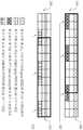
도 10은 본 명세서의 일 실시예에 의하여 생성 가능한 CoMP 전송 패턴 및 측정 패턴의 예를 보여주는 도면이다.FIG. 10 is a diagram illustrating an example of a CoMP transmission pattern and a measurement pattern that may be generated by an embodiment of the present specification. FIG.
도 6의 서브프레임을 적용할 경우, 제 2 유형(Rel-10, eICIC)의 매크로 사용자 단말이 송신하게 되는 서브프레임은 1012과 같으며, 제 2 유형(Rel-10, eICIC)의 피코 사용자 단말이 송신하게 되는 서브프레임은 1022와 같다.When the subframe of FIG. 6 is applied, the subframe transmitted by the macro user terminal of the second type Rel-10 and eICIC is equal to 1012, and the pico user terminal of the second type Rel-10 and eICIC. This subframe to be transmitted is equal to 1022.
이 경우, 제 3 유형, 즉 CoMP 전송을 하게 되는 서브프레임은 1012의 서브 셋이 될 수 있으며 서브셋은 네트워크 상태 및 CoMP 단말의 상태 등을 고려하여 1031, 1032, 1033, 1034, 1035 등이 될 수 있다. 그리고 각각의 전송 패턴에 대해 사용자 단말에게 제공되는 측정 패턴은 전송 패턴의 서브셋이 된다. CoMP 전송 패턴인 1031의 서브셋이 되는 측정 패턴은 1051에 도시된 패턴 중 하나가 될 수 있다. 마찬가지로 1032의 서브셋이 되는 측정 패턴은 1052에 도시된 패턴 중 하나, 1035의 서브셋이 되는 측정 패턴은 1055에 도시된 패턴 중 하나가 될 수 있다. 도 10에는 서브셋의 일부만 표시한 것이므로 다른 전송 패턴과 측정 패턴들도 생성될 수 있다.
In this case, the third type, that is, the subframe to which CoMP transmission may be a subset of 1012, and the subset may be 1031, 1032, 1033, 1034, 1035, etc. in consideration of the network state and the state of the CoMP terminal. have. And the measurement pattern provided to the user terminal for each transmission pattern is a subset of the transmission pattern. The measurement pattern, which is a subset of 1031 which is a CoMP transmission pattern, may be one of the patterns shown in 1051. Similarly, the measurement pattern that is a subset of 1032 may be one of the patterns shown in 1052, and the measurement pattern that is a subset of 1035 may be one of the patterns shown in 1055. Since only a part of the subset is displayed in FIG. 10, other transmission patterns and measurement patterns may also be generated.
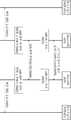
도 11은 본 명세서의 일 실시예에 의한 CoMP 전송을 수행하는 기지국에서 측정 패턴을 생성하여 단말에 제공하는 과정을 보여주는 도면이다. 도 11의 기지국은 매크로 기지국을 중심으로 설명한다.FIG. 11 is a diagram illustrating a process of generating a measurement pattern and providing the measurement pattern to a terminal in a base station performing CoMP transmission according to an embodiment of the present specification. The base station of FIG. 11 is described centering on the macro base station.
제 1 기지국 및 제 2 기지국이 제 1 사용자 단말에 협력형 통신을 제공하는 방법을 중심으로 하며, 제 1 기지국의 일 실시예는 매크로 기지국이며, 제 2 기지국의 일 실시예는 피코 기지국, 그리고 제 1 사용자 단말의 일 실시예는 CoMP 모드로 동작하는 매크로 사용자 단말이며, 제 2, 3 사용자 단말의 일 실시예는 eICIC 방식으로 동작하는 사용자 단말이다.A method for providing cooperative communication to a first user terminal by a first base station and a second base station is provided. An embodiment of the first base station is a macro base station, and an embodiment of the second base station is a pico base station, and One embodiment of the first user terminal is a macro user terminal operating in CoMP mode, one embodiment of the second, third user terminal is a user terminal operating in the eICIC method.
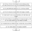
상기 제 1 기지국은 오직 제 1 기지국과 일정 기간 동안 신호를 송수신하는 제 2 사용자 단말과의 신호 송수신을 위한 제 2 ABS 패턴을 설정한다(S1110). 그리고, 상기 제 1 기지국은 상기 제 2 ABS 패턴의 부분 집합이 되는 제 1 ABS 패턴을 상기 제 1 사용자 단말과의 신호 송수신을 위한 패턴으로 설정한다(S1120). 이후, 상기 제 1 사용자 단말에게 상기 제 1 ABS 패턴의 부분 집합을 측정 패턴으로 하여 상기 제 1 사용자 단말에게 상기 측정 패턴을 송신한다(S1130). 그리고 상기 측정 패턴에 따라 상기 협력형 무선 통신 시스템을 위한 신호를 송신하며(S1140), 상기 제 1 사용자 단말로부터 측정 결과를 수신하게 된다(S1150).The first base station sets a second ABS pattern for signal transmission and reception with a second user terminal that transmits and receives a signal only for a predetermined period of time with the first base station (S1110). The first base station sets the first ABS pattern, which is a subset of the second ABS pattern, as a pattern for transmitting and receiving a signal with the first user terminal (S1120). Thereafter, the measurement pattern is transmitted to the first user terminal using the subset of the first ABS pattern as the measurement pattern to the first user terminal (S1130). The signal for the cooperative wireless communication system is transmitted according to the measurement pattern (S1140), and the measurement result is received from the first user terminal (S1150).
제 1 기지국이 제 1 ABS 패턴을 상기 제 1 사용자 단말과의 신호 송수신을 위한 패턴으로 설정하기 전에 상기 제 2 기지국이 오직 제 2 기지국과 일정 기간 동안 신호를 송수신하는 제 3 사용자 단말과의 신호 송수신을 위하여 생성한 제 3 ABS 패턴에 대한 정보를 상기 제 2 기지국으로부터 수신하여, 이를 기준으로 제 1 ABS 패턴을 설정할 수 있다. 상기 제 2 ABS 패턴과 상기 제 3 ABS 패턴은 공통된 서브프레임을 포함하지 않도록 설정할 수 있다. 여기서 제 2ABS 패턴은 매크로 기지국에서의 eICIC ABS 패턴이 될 수 있고, 상기 제 3 ABS 패턴은 피코 기지국에서의 eICIC ABS 패턴이 될 수 있으며, 상기 제 1 ABS 패턴은 CoMP 전송을 위한 ABS 패턴이 될 수 있다.
Before a first base station sets a first ABS pattern as a pattern for signal transmission and reception with the first user terminal, the second base station transmits and receives a signal with a third user terminal that transmits and receives a signal only with the second base station for a period of time. Information on the third ABS pattern generated for the purpose of receiving from the second base station, it can set the first ABS pattern based on this. The second ABS pattern and the third ABS pattern may be set not to include a common subframe. The second ABS pattern may be an eICIC ABS pattern in the macro base station, the third ABS pattern may be an eICIC ABS pattern in the pico base station, and the first ABS pattern may be an ABS pattern for CoMP transmission. have.
도 12는 본 명세서의 일 실시예에 의한 CoMP 전송을 수행하는 기지국에서 측정 패턴을 생성하여 단말에 제공하는 과정을 보여주는 도면이다. 도 12의 기지국은 피코 기지국을 중심으로 설명한다.12 is a diagram illustrating a process of generating a measurement pattern and providing the measurement pattern to a terminal in a base station performing CoMP transmission according to an embodiment of the present specification. The base station of FIG. 12 will be described based on the pico base station.
제 1 기지국 및 제 2 기지국이 제 1 사용자 단말에 협력형 통신을 제공하는 방법을 중심으로 하며, 제 1 기지국의 일 실시예는 피코 기지국이며, 제 2 기지국의 일 실시예는 매크로 기지국, 그리고 제 1 사용자 단말의 일 실시예는 CoMP 모드로 동작하는 피코 사용자 단말이며, 제 2, 3 사용자 단말의 일 실시예는 eICIC 방식으로 동작하는 사용자 단말이다.A method of providing cooperative communication to a first user terminal by a first base station and a second base station is provided, wherein an embodiment of the first base station is a pico base station, and an embodiment of the second base station is a macro base station, and One embodiment of the first user terminal is a pico user terminal operating in the CoMP mode, one embodiment of the second, third user terminal is a user terminal operating in the eICIC method.
상기 제 1 기지국은 오직 제 1 기지국과 일정 기간 동안 신호를 송수신하는 제 2 사용자 단말과의 신호 송수신을 위한 제 2 ABS 패턴을 설정한다(S1210). 그리고 상기 제 2 ABS 패턴에 대한 정보를 상기 제 2 기지국에 송신한다(S1220). 이후, 상기 제 2 기지국으로부터, 제 1 ABS 패턴에 대한 정보를 수신하게 된다(S1230). 제 1 ABS 패턴은 오직 상기 제 2 기지국과 일정 기간 동안 신호를 송수신하는 제 3 사용자 단말과의 신호 송수신을 위한 제 3 ABS 패턴의 부분 집합이 되는 것을 의미한다.The first base station sets a second ABS pattern for signal transmission and reception with a second user terminal that transmits and receives a signal only with the first base station for a predetermined period of time (S1210). In operation S1220, information about the second ABS pattern is transmitted to the second base station. Thereafter, information on the first ABS pattern is received from the second base station (S1230). The first ABS pattern means that the first ABS pattern is a subset of the third ABS pattern for signal transmission and reception with a third user terminal that transmits and receives a signal with the second base station for a predetermined period of time.
상기 제 1 ABS 패턴을 상기 제 2 기지국으로부터 수신한 후, 상기 제 1 사용자 단말과의 신호 송수신을 위한 패턴으로 설정한다(S1240). 그리고, 상기 제 1 사용자 단말에 상기 제 1 ABS 패턴의 부분 집합을 측정 패턴으로 하여 상기 제 1 사용자 단말에게 상기 측정 패턴을 송신한다(S1250). 이후, 상기 측정 패턴에 따라 상기 협력형 무선 통신 시스템을 위한 신호를 송신하고(S1260), 상기 제 1 사용자 단말로부터 측정 결과를 수신하게 된다(S1270).After receiving the first ABS pattern from the second base station, it is set as a pattern for transmitting and receiving a signal with the first user terminal (S1240). The measurement pattern is transmitted to the first user terminal using the subset of the first ABS pattern as the measurement pattern to the first user terminal (S1250). Thereafter, a signal for the cooperative wireless communication system is transmitted according to the measurement pattern (S1260), and a measurement result is received from the first user terminal (S1270).
상기 제 2 ABS 패턴과 상기 제 3 ABS 패턴은 공통된 서브프레임을 포함하지 않도록 설정할 수 있다. 여기서 제 2 ABS 패턴은 피코 기지국에서의 eICIC ABS 패턴이 될 수 있고, 상기 제 3 ABS 패턴은 매크로 기지국에서의 eICIC ABS 패턴이 될 수 있으며, 상기 제 1 ABS 패턴은 CoMP 전송을 위한 ABS 패턴이 될 수 있다.
The second ABS pattern and the third ABS pattern may be set not to include a common subframe. Here, the second ABS pattern may be an eICIC ABS pattern at the pico base station, the third ABS pattern may be an eICIC ABS pattern at the macro base station, and the first ABS pattern may be an ABS pattern for CoMP transmission. Can be.
도 13은 본 명세서의 일 실시예에 의한 CoMP 전송을 수행하는 사용자 단말이 측정 패턴을 수신하여 이에 따라 신호를 측정하는 도면이다. 도 13의 사용자 단말은 매크로 사용자 단말을 중심으로 설명한다.13 is a diagram of a user terminal performing CoMP transmission according to one embodiment of the present specification to receive a measurement pattern and measure a signal accordingly. The user terminal of FIG. 13 will be described based on the macro user terminal.
제 1 사용자 단말이 제 1 기지국 및 제 2 기지국과 협력형 통신을 수행하는 방법을 중심으로 하며, 제 1 기지국의 일 실시예는 매크로 기지국이며, 제 2 기지국의 일 실시예는 피코 기지국, 그리고 제 1 사용자 단말의 일 실시예는 CoMP 모드로 동작하는 매크로 사용자 단말이며, 제 2, 3 사용자 단말의 일 실시예는 eICIC 방식으로 동작하는 사용자 단말이다.A method for performing cooperative communication with a first base station and a second base station by a first user terminal is provided. An embodiment of the first base station is a macro base station, and an embodiment of the second base station is a pico base station, and One embodiment of the first user terminal is a macro user terminal operating in CoMP mode, one embodiment of the second, third user terminal is a user terminal operating in the eICIC method.
상기 제 1 사용자 단말은 상기 제 1 기지국으로부터 제 1 ABS 패턴의 부분 집합인 측정 패턴을 수신한다(S1310). 그리고 상기 측정 패턴에 따라 상기 제 1 기지국 및 상기 제 2 기지국으로부터 송신되는 신호를 측정하여(S1320), 상기 측정 결과를 상기 제 1 기지국 또는 상기 제 2 기지국에 송신한다(S1330). 상기 제 1 ABS 패턴은 오직 제 1 기지국과 일정 기간 동안 신호를 송수신하는 제 2 사용자 단말과의 신호 송수신을 위한 제 2 ABS 패턴의 부분 집합으로, 상기 제 2ABS 패턴은 매크로 기지국에서의 eICIC ABS 패턴이 될 수 있고, 상기 제 1 ABS 패턴은 CoMP 전송을 위한 ABS 패턴이 될 수 있다.
The first user terminal receives a measurement pattern that is a subset of the first ABS pattern from the first base station (S1310). The signal transmitted from the first base station and the second base station is measured according to the measurement pattern (S1320), and the measurement result is transmitted to the first base station or the second base station (S1330). The first ABS pattern is a subset of a second ABS pattern for signal transmission and reception with a second user terminal that transmits and receives a signal only for a predetermined period of time with the first base station, and the second ABS pattern is an eICIC ABS pattern in the macro base station. The first ABS pattern may be an ABS pattern for CoMP transmission.
도 14는 본 명세서의 일 실시예에 의한 CoMP 전송을 수행하는 사용자 단말이 측정 패턴을 수신하여 이에 따라 신호를 측정하는 도면이다. 도 14의 사용자 단말은 피코 사용자 단말을 중심으로 설명한다.14 is a diagram of a user terminal performing CoMP transmission according to one embodiment of the present specification to receive a measurement pattern and measure a signal accordingly. The user terminal of FIG. 14 will be described based on the pico user terminal.
제 1 기지국 및 제 2 기지국이 제 1 사용자 단말에 협력형 통신을 제공하는 방법을 중심으로 하며, 제 1 기지국의 일 실시예는 피코 기지국이며, 제 2 기지국의 일 실시예는 매크로 기지국, 그리고 제 1 사용자 단말의 일 실시예는 CoMP 모드로 동작하는 피코 사용자 단말이며, 제 2, 3 사용자 단말의 일 실시예는 eICIC 방식으로 동작하는 사용자 단말이다.A method of providing cooperative communication to a first user terminal by a first base station and a second base station is provided, wherein an embodiment of the first base station is a pico base station, and an embodiment of the second base station is a macro base station, and One embodiment of the first user terminal is a pico user terminal operating in the CoMP mode, one embodiment of the second, third user terminal is a user terminal operating in the eICIC method.
제 1 기지국은 상기 제 1 기지국으로부터 제 1 ABS 패턴의 부분 집합인 측정 패턴을 수신한다(S1410). 그리고 상기 측정 패턴에 따라 상기 제 1 기지국 및 상기 제 2 기지국으로부터 송신되는 신호를 측정하여(S1420), 상기 측정 결과를 상기 제 1 기지국 또는 상기 제 2 기지국에 송신한다. 이때, 상기 제 1 ABS 패턴은 오직 제 2 기지국과 일정 기간 동안 신호를 송수신하는 제 2 사용자 단말과의 신호 송수신을 위한 제 2 ABS 패턴의 부분 집합이 될 수 있다. 여기서 제 2ABS 패턴은 매크로 기지국에서의 eICIC ABS 패턴이 될 수 있으며, 상기 제 1 ABS 패턴은 CoMP 전송을 위한 ABS 패턴이 될 수 있다.
The first base station receives a measurement pattern that is a subset of the first ABS pattern from the first base station (S1410). The signal transmitted from the first base station and the second base station is measured according to the measurement pattern (S1420), and the measurement result is transmitted to the first base station or the second base station. In this case, the first ABS pattern may be a subset of the second ABS pattern for signal transmission and reception with a second user terminal that transmits and receives a signal only with a second base station for a predetermined period. Here, the second ABS pattern may be an eICIC ABS pattern in the macro base station, and the first ABS pattern may be an ABS pattern for CoMP transmission.
도 15는 본 명세서의 일 실시예에 의한 기지국의 구성을 보여주는 도면이다. 기지국은 매크로 기지국 및 피코 기지국 모두에 적용 가능하다. 따라서 두 가지 경우를 나누어 살펴보고자 한다.15 is a diagram illustrating a configuration of a base station according to one embodiment of the present specification. The base station is applicable to both macro base stations and pico base stations. Therefore, we will divide the two cases.
전체 구성은 패턴 설정부(1510), 제어부(1520), 및 송수신부(1530)으로 구성된다. 송수신부(1530)는 측정 패턴에 따라 상기 협력형 무선 통신 시스템을 위한 신호를 송신하며, 패턴 설정부(1510)는 상기 측정 패턴을 생성한다. 상기 제어부(1520)는 상기 송수신부(1530)가 사용자 단말에게 상기 협력형 무선통신 시스템에 적합한 ABS 패턴의 부분 집합을 측정 패턴으로 하여 상기 사용자 단말에 송신하도록 제어한다.The overall configuration is composed of a pattern setting unit 1510, a control unit 1520, and a transceiver 1530. The transceiver 1530 transmits a signal for the cooperative wireless communication system according to the measurement pattern, and the pattern setting unit 1510 generates the measurement pattern. The controller 1520 controls the transceiver 1530 to transmit the subset of ABS patterns suitable for the cooperative wireless communication system to the user terminal as a measurement pattern.
보다 상세히 살펴보면 매크로 기지국인 경우와 피코 기지국인 경우로 나누어서 살펴볼 수 있다.In more detail, it can be divided into a case of a macro base station and a case of a pico base station.
i) 매크로 기지국의 구성에 적용할 경우 다음과 같이 각각의 구성요소가 동작하게 된다.i) When applied to the configuration of the macro base station, each component operates as follows.
여기서 제 1 기지국의 일 실시예는 매크로 기지국이며, 제 2 기지국의 일 실시예는 피코 기지국, 그리고 제 1 사용자 단말의 일 실시예는 CoMP 모드로 동작하는 매크로 사용자 단말이며, 제 2, 3 사용자 단말의 일 실시예는 eICIC 방식으로 동작하는 사용자 단말이다.Here, an embodiment of the first base station is a macro base station, an embodiment of the second base station is a pico base station, and an embodiment of the first user terminal is a macro user terminal operating in a CoMP mode, and second and third user terminals. An embodiment of the is a user terminal operating in the eICIC scheme.
패턴 설정부(1510)는 상기 제 1 기지국이 오직 제 1 기지국과 일정 기간 동안 신호를 송수신하는 제 2 사용자 단말과의 신호 송수신을 위한 제 2 ABS 패턴을 설정하고 상기 제 2 ABS 패턴의 부분 집합이 되는 제 1 ABS 패턴을 상기 제 1 사용자 단말과의 신호 송수신을 위한 패턴으로 설정한다. 그리고 상기 제어부(1520)는 상기 제 1 사용자 단말에 상기 제 1 ABS 패턴의 부분 집합을 상기 측정 패턴으로 하여 상기 제 1 사용자 단말에 상기 측정 패턴에 대한 정보를 송신하도록 상기 송수신부(1530)를 제어하게 된다.The pattern setting unit 1510 sets a second ABS pattern for signal transmission and reception with a second user terminal through which the first base station transmits and receives a signal with only the first base station for a predetermined period of time, and a subset of the second ABS pattern is set. The first ABS pattern is set as a pattern for signal transmission and reception with the first user terminal. The controller 1520 controls the transceiver 1530 to transmit the information about the measurement pattern to the first user terminal by using the subset of the first ABS pattern as the measurement pattern to the first user terminal. Done.
또한, 상기 송수신부(1530)는 상기 제 2 기지국이 오직 제 2 기지국과 일정 기간 동안 신호를 송수신하는 제 3 사용자 단말과의 신호 송수신을 위하여 생성한 제 3 ABS 패턴에 대한 정보를 상기 제 2 기지국으로부터 수신하며, 상기 제어부(1520)는 상기 제 3 ABS 패턴과 공통된 서브프레임을 가지지 않는 상기 제 2 ABS 패턴을 선정할 수 있다.In addition, the transceiver 1530 is configured to transmit information about a third ABS pattern generated by the second base station to transmit and receive a signal with a third user terminal that transmits and receives a signal with a second base station only for a predetermined period of time. And the controller 1520 may select the second ABS pattern that does not have a subframe in common with the third ABS pattern.
이 경우, 상기 제 2 ABS 패턴과 상기 제 3 ABS 패턴은 공통된 서브프레임을 포함하지 않도록 설정할 수 있다. 여기서 제 2ABS 패턴은 매크로 기지국에서의 eICIC ABS 패턴이 될 수 있고, 상기 제 3 ABS 패턴은 피코 기지국에서의 eICIC ABS 패턴이 될 수 있으며, 상기 제 1 ABS 패턴은 CoMP 전송을 위한 ABS 패턴이 될 수 있다.
In this case, the second ABS pattern and the third ABS pattern may be set not to include a common subframe. The second ABS pattern may be an eICIC ABS pattern in the macro base station, the third ABS pattern may be an eICIC ABS pattern in the pico base station, and the first ABS pattern may be an ABS pattern for CoMP transmission. have.
ii) 피코 기지국의 구성에 적용할 경우 다음과 같이 각각의 구성요소가 동작하게 된다.ii) When applied to the configuration of the pico base station, each component operates as follows.
여기서 제 1 기지국의 일 실시예는 피코 기지국이며, 제 2 기지국의 일 실시예는 매크로 기지국, 그리고 제 1 사용자 단말의 일 실시예는 CoMP 모드로 동작하는 피코 사용자 단말이며, 제 2, 3 사용자 단말의 일 실시예는 eICIC 방식으로 동작하는 사용자 단말이다.Here, one embodiment of the first base station is a pico base station, one embodiment of the second base station is a macro base station, and one embodiment of the first user terminal is a pico user terminal operating in the CoMP mode, second, third user terminal An embodiment of the is a user terminal operating in the eICIC scheme.
패턴 설정부(1510)는 상기 제 1 기지국이 오직 제 1 기지국과 일정 기간 동안 신호를 송수신하는 제 2 사용자 단말과의 신호 송수신을 위한 제 2 ABS 패턴을 설정하고, 상기 제어부(1520)는 상기 제 2 ABS 패턴에 대한 정보를 상기 송수신부(1530)가 상기 제 2 기지국에 송신하도록 제어한다. 그리고 상기 송수신부(1530)가 오직 상기 제 2 기지국과 일정 기간 동안 신호를 송수신하는 제 3 사용자 단말과의 신호 송수신을 위한 제 3 ABS 패턴의 부분 집합이 되는 제 1 ABS 패턴에 대한 정보를 상기 제 2 기지국으로부터 수신하게 되면, 상기 패턴 설정부(1510)는 상기 제 1 ABS 패턴을 상기 제 1 사용자 단말과의 신호 송수신을 위한 패턴으로 설정한다. 이후, 상기 제어부(1520)는 상기 송수신부가 상기 제 1 사용자 단말에 상기 제 1 ABS 패턴의 부분 집합을 측정 패턴으로 하여 상기 제 1 사용자 단말에 송신하도록 제어하게 된다. 여기서 상기 제 2 ABS 패턴과 상기 제 3 ABS 패턴은 공통된 서브프레임을 포함하지 않도록 설정할 수 있다. 여기서 제 2ABS 패턴은 피코 기지국에서의 eICIC ABS 패턴이 될 수 있고, 상기 제 3 ABS 패턴은 매크로 기지국에서의 eICIC ABS 패턴이 될 수 있으며, 상기 제 1 ABS 패턴은 CoMP 전송을 위한 ABS 패턴이 될 수 있다.
The pattern setting unit 1510 sets a second ABS pattern for signal transmission and reception with a second user terminal through which the first base station transmits and receives a signal with only the first base station for a predetermined period of time, and the controller 1520 is configured to perform the second ABS pattern. 2 Controls the transceiver 1530 to transmit the information about the ABS pattern to the second base station. The information on the first ABS pattern, which is a subset of the third ABS pattern, for transmitting and receiving the signal to and from the third user terminal through which the transceiver unit 1530 transmits and receives a signal with the second base station only for a predetermined period of time, 2, when receiving from the base station, the pattern setting unit 1510 sets the first ABS pattern as a pattern for transmitting and receiving a signal with the first user terminal. Thereafter, the controller 1520 controls the transceiver to transmit the subset of the first ABS pattern as the measurement pattern to the first user terminal to the first user terminal. Here, the second ABS pattern and the third ABS pattern may be set not to include a common subframe. The second ABS pattern may be an eICIC ABS pattern in a pico base station, the third ABS pattern may be an eICIC ABS pattern in a macro base station, and the first ABS pattern may be an ABS pattern for CoMP transmission. have.
도 16은 본 명세서의 일 실시예에 의한 사용자 단말의 구성을 보여주는 도면이다. 사용자 단말은 매크로 사용자 단말 및 피코 사용자 단말 모두에 적용 가능하다. 따라서 두 가지 경우를 나누어 살펴보고자 한다.16 is a diagram illustrating a configuration of a user terminal according to one embodiment of the present specification. The user terminal is applicable to both the macro user terminal and the pico user terminal. Therefore, we will divide the two cases.
전체 구성은 수신부(1610), 제어부(1620), 및 송신부(1630)으로 구성된다. 수신부(1610)는 기지국으로부터 ABS 패턴의 부분 집합인 측정 패턴을 수신하며, 제어부(1620)는 상기 측정 패턴에 따라 상기 기지국(제 1 기지국) 및 협력형 통신을 수행하는 다른 기지국(제 2 기지국)으로부터 송신되는 신호를 측정한다. 그리고 송신부(1630)는 상기 측정 결과를 상기 제 1 기지국 또는 상기 제 2 기지국에 송신하게 된다.The overall configuration includes a receiver 1610, a controller 1620, and a transmitter 1630. The receiver 1610 receives a measurement pattern which is a subset of an ABS pattern from a base station, and the controller 1620 is configured to perform cooperative communication with the base station (first base station) and another base station (second base station) according to the measurement pattern. Measure the signal from the transmitter. The transmitter 1630 transmits the measurement result to the first base station or the second base station.
보다 상세히 살펴보면 매크로 사용자 단말인 경우와 피코 사용자 단말인 경우로 나누어서 살펴볼 수 있다.In more detail, it can be divided into a case of a macro user terminal and a case of a pico user terminal.
i) 매크로 단말의 구성에 적용할 경우 다음과 같은 특징을 가지게 된다.i) When applied to the configuration of the macro terminal has the following characteristics.
여기서 제 1 기지국의 일 실시예는 매크로 기지국이며, 제 2 기지국의 일 실시예는 피코 기지국, 그리고 제 1 사용자 단말의 일 실시예는 CoMP 모드로 동작하는 매크로 사용자 단말이며, 제 2, 3 사용자 단말의 일 실시예는 eICIC 방식으로 동작하는 사용자 단말이다.Here, an embodiment of the first base station is a macro base station, an embodiment of the second base station is a pico base station, and an embodiment of the first user terminal is a macro user terminal operating in a CoMP mode, and second and third user terminals. An embodiment of the is a user terminal operating in the eICIC scheme.
상기 ABS 패턴(제 1 ABS 패턴)은 오직 제 1 기지국과 일정 기간 동안 신호를 송수신하는 제 2 사용자 단말과의 신호 송수신을 위한 제 2 ABS 패턴의 부분 집합이며, 상기 측정 패턴은 신호가 송수신되는 서브프레임을 지시하는 정보를 포함하게 된다. 상기 제 2ABS 패턴은 매크로 기지국에서의 eICIC ABS 패턴이 될 수 있고, 상기 제 1 ABS 패턴은 CoMP 전송을 위한 ABS 패턴이 될 수 있다.The ABS pattern (first ABS pattern) is a subset of a second ABS pattern for signal transmission and reception with a second user terminal that transmits and receives a signal only with a first base station for a predetermined period, and the measurement pattern is a sub Contains information indicating the frame. The second ABS pattern may be an eICIC ABS pattern in the macro base station, and the first ABS pattern may be an ABS pattern for CoMP transmission.
ii) 피코 단말의 구성에 적용할 경우 다음과 같은 특징을 가지게 된다.ii) When applied to the configuration of the pico terminal has the following characteristics.
상기 ABS 패턴(제 1 ABS 패턴)은 오직 제 2 기지국과 일정 기간 동안 신호를 송수신하는 제 2 사용자 단말과의 신호 송수신을 위한 제 2 ABS 패턴의 부분 집합이며, 상기 측정 패턴은 신호가 송수신되는 서브프레임을 지시하는 정보를 포함하게 된다. 상기 제 2ABS 패턴은 매크로 기지국에서의 eICIC ABS 패턴이 될 수 있고, 상기 제 1 ABS 패턴은 CoMP 전송을 위한 ABS 패턴이 될 수 있다.The ABS pattern (first ABS pattern) is a subset of a second ABS pattern for signal transmission and reception with a second user terminal that transmits and receives a signal only with a second base station for a predetermined period, and the measurement pattern is a sub Contains information indicating the frame. The second ABS pattern may be an eICIC ABS pattern in the macro base station, and the first ABS pattern may be an ABS pattern for CoMP transmission.
ABS 패턴은 앞서 살펴본 바와 같이 신호가 송수신되는 서브프레임을 지시하는 정보가 될 수 있으나, 이에 한정되는 것은 아니며, 신호의 송수신을 지시하기 위한 다양한 방식으로 구현될 수 있다.As described above, the ABS pattern may be information indicating a subframe through which a signal is transmitted and received, but is not limited thereto. The ABS pattern may be implemented in various ways for instructing transmission and reception of a signal.
사용자 단말이 측정 결과를 제 1 기지국 또는 제 2 기지국에 송신하는 것은 두 기지국 중 어느 하나 이상에 송신하는 것을 포함한다.The transmission of the measurement result to the first base station or the second base station by the user terminal includes transmitting to one or more of the two base stations.
LTE Rel-10 표준은 무선 용량 증대 및 보다 효율적인 네트웍 자원 관리를 위하여 헤테로지니어스 네트워크(Heterogeneous network) 및 상기 네트워크에 적합한 eICIC 기법을 도입하였으며, LTE Rel-11 표준은 기지국 또는 셀 간 협력 통신을 통해 통신 용량을 증가시키는 CoMP 기법을 도입하고자 한다. 본 명세서에서는 Rel-10에 의해 소개된 eICIC 기법을 사용하는 헤테로지니어스 네트워크에 적응된 단말 통신에 영향을 주지 않으면서 헤테로지니어스 네트워크에서 CoMP을 구현하기 위한 신호 전송 및 채널 추정 패턴 설정법을 제시한다.The LTE Rel-10 standard introduces a heterogeneous network and eICIC technique suitable for the network for increasing wireless capacity and more efficiently managing network resources. The LTE Rel-11 standard communicates through cooperative communication between base stations or cells. We want to introduce a CoMP technique to increase the capacity. In this specification, a signal transmission and channel estimation pattern setting method for implementing CoMP in a heterogeneous network without affecting a terminal communication adapted to a heterogeneous network using an eICIC technique introduced by Rel-10 is presented.
이상의 설명은 본 발명의 기술 사상을 예시적으로 설명한 것에 불과한 것으로서, 본 발명이 속하는 기술 분야에서 통상의 지식을 가진 자라면 본 발명의 본질적인 특성에서 벗어나지 않는 범위에서 다양한 수정 및 변형이 가능할 것이다. 따라서, 본 발명에 개시된 실시예들은 본 발명의 기술 사상을 한정하기 위한 것이 아니라 설명하기 위한 것이고, 이러한 실시예에 의하여 본 발명의 기술 사상의 범위가 한정되는 것은 아니다. 본 발명의 보호 범위는 아래의 청구범위에 의하여 해석되어야 하며, 그와 동등한 범위 내에 있는 모든 기술 사상은 본 발명의 권리범위에 포함되는 것으로 해석되어야 할 것이다.The foregoing description is merely illustrative of the technical idea of the present invention, and various changes and modifications may be made by those skilled in the art without departing from the essential characteristics of the present invention. Therefore, the embodiments disclosed in the present invention are intended to illustrate rather than limit the scope of the present invention, and the scope of the technical idea of the present invention is not limited by these embodiments. The protection scope of the present invention should be interpreted by the following claims, and all technical ideas within the equivalent scope should be interpreted as being included in the scope of the present invention.
Claims (14)
Translated fromKorean상기 제 1 기지국이 오직 제 1 기지국과 일정 기간 동안 신호를 송수신하는 제 2 사용자 단말과의 신호 송수신을 위한 제 2 ABS 패턴을 설정하는 단계;
상기 제 2 ABS 패턴의 부분 집합이 되는 제 1 ABS 패턴을 상기 제 1 사용자 단말과의 신호 송수신을 위한 패턴으로 설정하는 단계;
상기 제 1 사용자 단말에 상기 제 1 ABS 패턴의 부분 집합을 측정 패턴으로 하여 상기 제 1 사용자 단말에게 상기 측정 패턴을 송신하는 단계; 및
상기 측정 패턴에 따라 상기 협력형 무선 통신 시스템을 위한 신호를 송신하는 단계를 포함하는, 협력형 무선 통신 시스템에서 신호의 송수신을 위한 측정 패턴을 송신하는 방법.
A method for providing cooperative communication to a first user terminal by a first base station and a second base station, the method comprising:
Setting, by the first base station, a second ABS pattern for transmitting and receiving a signal to and from a second user terminal that transmits and receives a signal to and from a first base station only;
Setting a first ABS pattern, which is a subset of the second ABS pattern, as a pattern for transmitting and receiving a signal with the first user terminal;
Transmitting the measurement pattern to the first user terminal by using the subset of the first ABS pattern as the measurement pattern to the first user terminal; And
Transmitting a signal for the cooperative wireless communication system in accordance with the measurement pattern.
상기 제 2 기지국이 오직 제 2 기지국과 일정 기간 동안 신호를 송수신하는 제 3 사용자 단말과의 신호 송수신을 위하여 생성한 제 3 ABS 패턴에 대한 정보를 상기 제 2 기지국으로부터 수신하는 단계를 더 포함하며,
상기 제 2 ABS 패턴과 상기 제 3 ABS 패턴은 공통된 서브프레임을 포함하지 않는 것을 특징으로 하는, 협력형 무선 통신 시스템에서 신호의 송수신을 위한 측정 패턴을 송신하는 방법.
The method of claim 1,
Receiving information from the second base station about the third ABS pattern generated by the second base station for transmitting and receiving a signal with a third user terminal that transmits and receives a signal only with a second base station for a predetermined period of time;
And the second ABS pattern and the third ABS pattern do not include a common subframe. The method of claim 2, wherein the second ABS pattern and the third ABS pattern do not include a common subframe.
상기 ABS 패턴은 신호가 송수신되는 서브프레임을 지시하는 정보를 포함하는 것을 특징으로 하는, 협력형 무선 통신 시스템에서 신호의 송수신을 위한 측정 패턴을 송신하는 방법.
The method of claim 1,
The ABS pattern is a method for transmitting a measurement pattern for transmitting and receiving signals in a cooperative wireless communication system, characterized in that it comprises information indicating a subframe in which the signal is transmitted and received.
상기 제 1 기지국이 오직 제 1 기지국과 일정 기간 동안 신호를 송수신하는 제 2 사용자 단말과의 신호 송수신을 위한 제 2 ABS 패턴을 설정하는 단계;
상기 제 2 ABS 패턴에 대한 정보를 상기 제 2 기지국에 송신하는 단계; 및
오직 상기 제 2 기지국과 일정 기간 동안 신호를 송수신하는 제 3 사용자 단말과의 신호 송수신을 위한 제 3 ABS 패턴의 부분 집합이 되는 제 1 ABS 패턴에 대한 정보를 상기 제 2 기지국으로부터 수신하여 상기 제 1 사용자 단말과의 신호 송수신을 위한 패턴으로 설정하는 단계;
상기 제 1 사용자 단말에 상기 제 1 ABS 패턴의 부분 집합을 측정 패턴으로 하여 상기 제 1 사용자 단말에게 상기 측정 패턴을 송신하는 단계; 및
상기 측정 패턴에 따라 상기 협력형 무선 통신 시스템을 위한 신호를 송신하는 단계를 포함하는, 협력형 무선 통신 시스템에서 신호의 송수신을 위한 측정 패턴을 송신하는 방법.
A method for providing cooperative communication to a first user terminal by a first base station and a second base station, the method comprising:
Setting, by the first base station, a second ABS pattern for transmitting and receiving a signal to and from a second user terminal that transmits and receives a signal to and from a first base station only;
Transmitting information on the second ABS pattern to the second base station; And
The first base station receives information about the first ABS pattern, which is a subset of the third ABS pattern for signal transmission and reception with a third user terminal that transmits and receives a signal for a predetermined period of time with the second base station, by receiving the information from the second base station. Setting a pattern for signal transmission and reception with a user terminal;
Transmitting the measurement pattern to the first user terminal by using the subset of the first ABS pattern as the measurement pattern to the first user terminal; And
Transmitting a signal for the cooperative wireless communication system in accordance with the measurement pattern.
상기 ABS 패턴은 신호가 송수신되는 서브프레임을 지시하는 정보를 포함하는 것을 특징으로 하는, 협력형 무선 통신 시스템에서 신호의 송수신을 위한 측정 패턴을 송신하는 방법.
The method of claim 4, wherein
The ABS pattern is a method for transmitting a measurement pattern for transmitting and receiving signals in a cooperative wireless communication system, characterized in that it comprises information indicating a subframe in which the signal is transmitted and received.
상기 제 1 기지국으로부터 제 1 ABS 패턴의 부분 집합인 측정 패턴을 수신하는 단계; 및
상기 측정 패턴에 따라 상기 제 1 기지국 및 상기 제 2 기지국으로부터 송신되는 신호를 측정하여 측정 결과를 상기 제 1 기지국 또는 상기 제 2 기지국 중 어느 하나 이상에 송신하는 단계를 포함하며;
상기 제 1 ABS 패턴은 오직 제 1 기지국과 일정 기간 동안 신호를 송수신하는 제 2 사용자 단말과의 신호 송수신을 위한 제 2 ABS 패턴의 부분 집합인 것을 특징으로 하는, 협력형 무선 통신 시스템에서 신호의 송수신을 위한 측정 패턴을 수신하는 방법.
In the method of the first user terminal performs the cooperative communication with the first base station and the second base station,
Receiving a measurement pattern that is a subset of a first ABS pattern from the first base station; And
Measuring a signal transmitted from the first base station and the second base station according to the measurement pattern and transmitting a measurement result to any one or more of the first base station and the second base station;
The first ABS pattern is a subset of a second ABS pattern for signal transmission and reception with a second user terminal that transmits and receives a signal only for a predetermined period of time with the first base station, transmission and reception of signals in the cooperative wireless communication system How to receive a measurement pattern for the.
상기 측정 패턴은 신호가 송수신되는 서브프레임을 지시하는 정보를 포함하는 것을 특징으로 하는, 협력형 무선 통신 시스템에서 신호의 송수신을 위한 측정 패턴을 수신하는 방법.
The method according to claim 6,
And the measurement pattern includes information indicating a subframe through which a signal is transmitted and received.
상기 제 1 기지국으로부터 제 1 ABS 패턴의 부분 집합인 측정 패턴을 수신하는 단계; 및
상기 측정 패턴에 따라 상기 제 1 기지국 및 상기 제 2 기지국으로부터 송신되는 신호를 측정하여 측정 결과를 상기 제 1 기지국 또는 상기 제 2 기지국 중 어느 하나 이상에 송신하는 단계를 포함하며;
상기 제 1 ABS 패턴은 오직 제 2 기지국과 일정 기간 동안 신호를 송수신하는 제 2 사용자 단말과의 신호 송수신을 위한 제 2 ABS 패턴의 부분 집합인 것을 특징으로 하는, 협력형 무선 통신 시스템에서 신호의 송수신을 위한 측정 패턴을 수신하는 방법.
In the method of the first user terminal performs the cooperative communication with the first base station and the second base station,
Receiving a measurement pattern that is a subset of a first ABS pattern from the first base station; And
Measuring a signal transmitted from the first base station and the second base station according to the measurement pattern and transmitting a measurement result to any one or more of the first base station and the second base station;
The first ABS pattern is a subset of a second ABS pattern for signal transmission and reception with a second user terminal that transmits and receives a signal only for a predetermined period with a second base station, transmission and reception of signals in the cooperative wireless communication system How to receive a measurement pattern for the.
상기 측정 패턴은 신호가 송수신되는 서브프레임을 지시하는 정보를 포함하는 것을 특징으로 하는, 협력형 무선 통신 시스템에서 신호의 송수신을 위한 측정 패턴을 수신하는 방법.
The method of claim 8,
And the measurement pattern includes information indicating a subframe through which a signal is transmitted and received.
측정 패턴에 따라 상기 협력형 무선 통신 시스템을 위한 신호를 송신하는 송수신부;
상기 제 1 기지국이 오직 제 1 기지국과 일정 기간 동안 신호를 송수신하는 제 2 사용자 단말과의 신호 송수신을 위한 제 2 ABS 패턴을 설정하고 상기 제 2 ABS 패턴의 부분 집합이 되는 제 1 ABS 패턴을 상기 제 1 사용자 단말과의 신호 송수신을 위한 패턴으로 설정하는 패턴 설정부;
상기 제 1 사용자 단말에 상기 제 1 ABS 패턴의 부분 집합을 상기 측정 패턴으로 하여 상기 제 1 사용자 단말에 상기 측정 패턴에 대한 정보를 송신하도록 송수신부를 제어하는 제어부를 포함하며, 상기 ABS 패턴은 신호가 송수신되는 서브프레임을 지시하는 정보를 포함하는 것을 특징으로 하는, 기지국.
A wireless communication system in which a first base station and a second base station provide cooperative communication to a first user terminal,
A transceiver for transmitting a signal for the cooperative wireless communication system according to a measurement pattern;
The first base station sets a second ABS pattern for transmitting and receiving a signal with a second user terminal that transmits and receives a signal only for a predetermined period of time with the first base station and the first ABS pattern which is a subset of the second ABS pattern; A pattern setting unit configured to set a pattern for transmitting and receiving signals with the first user terminal;
And a controller configured to control a transceiver to transmit information on the measurement pattern to the first user terminal by using the subset of the first ABS pattern as the measurement pattern to the first user terminal, wherein the ABS pattern includes a signal. And information indicating the subframe to be transmitted and received.
상기 송수신부는 상기 제 2 기지국이 오직 제 2 기지국과 일정 기간 동안 신호를 송수신하는 제 3 사용자 단말과의 신호 송수신을 위하여 생성한 제 3 ABS 패턴에 대한 정보를 상기 제 2 기지국으로부터 수신하며,
상기 제어부는 상기 제 3 ABS 패턴과 공통된 서브프레임을 가지지 않는 상기 제 2 ABS 패턴을 선정하는 것을 특징으로 하는, 기지국.
The method of claim 10,
The transceiver unit receives information from the second base station about the third ABS pattern generated by the second base station for signal transmission and reception with a third user terminal that transmits and receives a signal only with a second base station for a predetermined period of time,
And the control unit selects the second ABS pattern that does not have a subframe in common with the third ABS pattern.
측정 패턴에 따라 상기 협력형 무선 통신 시스템을 위한 신호를 송신하는 송수신부;
상기 제 1 기지국이 오직 제 1 기지국과 일정 기간 동안 신호를 송수신하는 제 2 사용자 단말과의 신호 송수신을 위한 제 2 ABS 패턴을 설정하는 패턴 설정부; 및
상기 제 2 ABS 패턴에 대한 정보를 상기 송수신부가 상기 제 2 기지국에 송신하도록 제어하는 제어부를 포함하며,
상기 송수신부는 오직 상기 제 2 기지국과 일정 기간 동안 신호를 송수신하는 제 3 사용자 단말과의 신호 송수신을 위한 제 3 ABS 패턴의 부분 집합이 되는 제 1 ABS 패턴에 대한 정보를 상기 제 2 기지국으로부터 수신하고, 상기 패턴 설정부는 상기 제 1 ABS 패턴을 상기 제 1 사용자 단말과의 신호 송수신을 위한 패턴으로 설정하며,
상기 제어부는 상기 송수신부가 상기 제 1 사용자 단말에 상기 제 1 ABS 패턴의 부분 집합을 측정 패턴으로 하여 상기 제 1 사용자 단말에 송신하도록 제어하며,
상기 ABS 패턴은 신호가 송수신되는 서브프레임을 지시하는 정보를 포함하는 것을 특징으로 하는 것을 특징으로 하는, 기지국.
A wireless communication system in which a first base station and a second base station provide cooperative communication to a first user terminal,
A transceiver for transmitting a signal for the cooperative wireless communication system according to a measurement pattern;
A pattern setting unit configured to set a second ABS pattern for signal transmission and reception with a second user terminal through which the first base station transmits and receives a signal only with the first base station for a predetermined period of time; And
It includes a control unit for controlling the transmission and reception unit for transmitting the information about the second ABS pattern to the second base station,
The transceiver unit receives information on the first ABS pattern, which is a subset of the third ABS pattern for signal transmission and reception, with the third user terminal, which transmits and receives a signal with the second base station only for a predetermined period of time, from the second base station. The pattern setting unit sets the first ABS pattern as a pattern for transmitting and receiving a signal with the first user terminal.
The control unit controls the transceiver to transmit to the first user terminal a subset of the first ABS pattern as a measurement pattern to the first user terminal,
The ABS pattern is characterized in that it comprises information indicating a subframe in which a signal is transmitted and received, the base station.
상기 제 1 기지국으로부터 제 1 ABS 패턴의 부분 집합인 측정 패턴을 수신하는 수신부; 및
상기 측정 패턴에 따라 상기 제 1 기지국 및 상기 제 2 기지국으로부터 송신되는 신호를 측정하는 제어부;
상기 측정 결과를 상기 제 1 기지국 또는 상기 제 2 기지국 중 어느 하나 이상에 송신하는 송신부를 포함하며;
상기 제 1 ABS 패턴은 오직 제 1 기지국과 일정 기간 동안 신호를 송수신하는 제 2 사용자 단말과의 신호 송수신을 위한 제 2 ABS 패턴의 부분 집합이며, 상기 측정 패턴은 신호가 송수신되는 서브프레임을 지시하는 정보를 포함하는 것을 특징으로 하는, 사용자 단말.
A first user terminal performing cooperative communication with a first base station and a second base station,
A receiver for receiving a measurement pattern which is a subset of a first ABS pattern from the first base station; And
A control unit measuring a signal transmitted from the first base station and the second base station according to the measurement pattern;
A transmitter for transmitting the measurement result to any one or more of the first base station and the second base station;
The first ABS pattern is a subset of a second ABS pattern for signal transmission and reception with a second user terminal that transmits and receives a signal only for a predetermined period of time with the first base station, and the measurement pattern indicates a subframe in which the signal is transmitted and received. User information, characterized in that it comprises information.
상기 제 1 기지국으로부터 제 1 ABS 패턴의 부분 집합인 측정 패턴을 수신하는 수신부;
상기 측정 패턴에 따라 상기 제 1 기지국 및 상기 제 2 기지국으로부터 송신되는 신호를 측정하는 제어부; 및
상기 측정 결과를 상기 제 1 기지국 또는 상기 제 2 기지국 중 어느 하나 이상에 송신하는 송신부를 포함하며,
상기 제 1 ABS 패턴은 오직 제 2 기지국과 일정 기간 동안 신호를 송수신하는 제 2 사용자 단말과의 신호 송수신을 위한 제 2 ABS 패턴의 부분 집합이며, 상기 측정 패턴은 신호가 송수신되는 서브프레임을 지시하는 정보를 포함하는 것을 특징으로 하는, 사용자 단말.A first user terminal performing cooperative communication with a first base station and a second base station,
A receiver for receiving a measurement pattern which is a subset of a first ABS pattern from the first base station;
A control unit measuring a signal transmitted from the first base station and the second base station according to the measurement pattern; And
A transmitter for transmitting the measurement result to any one or more of the first base station and the second base station,
The first ABS pattern is a subset of a second ABS pattern for signal transmission and reception with a second user terminal that transmits and receives a signal only for a predetermined period of time with the second base station, and the measurement pattern indicates a subframe in which the signal is transmitted and received. User information, characterized in that it comprises information.
Priority Applications (3)
| Application Number | Priority Date | Filing Date | Title |
|---|---|---|---|
| KR1020110001995AKR20120080493A (en) | 2011-01-07 | 2011-01-07 | Method and apparatus for transmitting and receiving measurement pattern in comp system |
| PCT/KR2012/000096WO2012093858A2 (en) | 2011-01-07 | 2012-01-04 | Method and apparatus for transmitting and receiving measurement pattern in comp communication system |
| US13/978,521US20130286849A1 (en) | 2011-01-07 | 2012-01-04 | Method and apparatus for transmitting and receiving measurement pattern in comp communication system |
Applications Claiming Priority (1)
| Application Number | Priority Date | Filing Date | Title |
|---|---|---|---|
| KR1020110001995AKR20120080493A (en) | 2011-01-07 | 2011-01-07 | Method and apparatus for transmitting and receiving measurement pattern in comp system |
Publications (1)
| Publication Number | Publication Date |
|---|---|
| KR20120080493Atrue KR20120080493A (en) | 2012-07-17 |
Family
ID=46457848
Family Applications (1)
| Application Number | Title | Priority Date | Filing Date |
|---|---|---|---|
| KR1020110001995AWithdrawnKR20120080493A (en) | 2011-01-07 | 2011-01-07 | Method and apparatus for transmitting and receiving measurement pattern in comp system |
Country Status (3)
| Country | Link |
|---|---|
| US (1) | US20130286849A1 (en) |
| KR (1) | KR20120080493A (en) |
| WO (1) | WO2012093858A2 (en) |
Cited By (2)
| Publication number | Priority date | Publication date | Assignee | Title |
|---|---|---|---|---|
| KR20160008960A (en)* | 2014-07-15 | 2016-01-25 | 에스케이텔레콤 주식회사 | Base station and control method thereof, terminal device |
| US9949287B2 (en) | 2013-05-22 | 2018-04-17 | Huawei Technologies Co., Ltd. | Downlink transmission method in heterogeneous network, control device, base station and heterogeneous system |
Families Citing this family (19)
| Publication number | Priority date | Publication date | Assignee | Title |
|---|---|---|---|---|
| US20130336193A1 (en) | 2012-06-19 | 2013-12-19 | Qualcomm Incorporated | Network information for assisting user equipment |
| US9264097B2 (en) | 2009-06-04 | 2016-02-16 | Qualcomm Incorporated | Interference mitigation for downlink in a wireless communication system |
| WO2013138068A1 (en)* | 2012-03-13 | 2013-09-19 | Zte (Usa) Inc. | Interference management in the heterogeneous network |
| WO2013167163A1 (en)* | 2012-05-07 | 2013-11-14 | Nokia Siemens Networks Oy | Interference estimation for multipoint transmissions |
| EP2683192B1 (en)* | 2012-07-02 | 2014-12-24 | Alcatel Lucent | Apparatus, method and computer program product for determining at a base station transceiver a measurement configuration for a mobile station transceiver in relation to a sequence of frames with reduced or suspended transmission |
| JP6045843B2 (en)* | 2012-07-31 | 2016-12-14 | 株式会社Nttドコモ | COMMUNICATION SYSTEM, BASE STATION DEVICE, MOBILE TERMINAL DEVICE, AND COMMUNICATION METHOD |
| US9413502B2 (en)* | 2012-10-15 | 2016-08-09 | Headwater Partners LLC | Backhaul assisted by user equipment |
| CN103781125A (en)* | 2012-10-24 | 2014-05-07 | 普天信息技术研究院有限公司 | Method for adjusting uplink and downlink subframe configuration in heterogeneous network |
| CN103929771B (en) | 2013-01-11 | 2017-12-26 | 电信科学技术研究院 | A kind of coordinated multi-point transmission method and equipment |
| US9301281B2 (en)* | 2013-02-22 | 2016-03-29 | Blackberry Limited | Mechanisms for timing and signaling coordination in multi-point connectivity |
| JP2016515777A (en)* | 2013-04-03 | 2016-05-30 | 華為技術有限公司Huawei Technologies Co.,Ltd. | Method and apparatus for receiving and sending reference signals, user equipment, and base station |
| US9634741B2 (en) | 2013-07-29 | 2017-04-25 | Lg Electronics Inc. | Method and device for performing NIB CoMP transmission in wireless communication system |
| US9871628B2 (en)* | 2013-07-29 | 2018-01-16 | Lg Electronics Inc. | NIB CoMP transmission method and device in wireless communication system |
| US11277779B2 (en)* | 2014-01-28 | 2022-03-15 | Samsung Electronics Co., Ltd. | Method and apparatus for applying resources in heterogeneous network system |
| KR20150089890A (en) | 2014-01-28 | 2015-08-05 | 삼성전자주식회사 | Method and apparatus for compensating channel quality information and allocation resource in wireless communication system |
| WO2015115787A1 (en)* | 2014-01-28 | 2015-08-06 | 삼성전자 주식회사 | Method and apparatus for applying resources in heterogeneous network system |
| CN105873080B (en)* | 2015-01-23 | 2019-06-18 | 华为技术有限公司 | A kind of cooperative communication method and device in heterogeneous network |
| US10638498B2 (en)* | 2015-02-27 | 2020-04-28 | At&T Intellectual Property I, L.P. | Frequency selective almost blank subframes |
| US10212729B1 (en)* | 2016-12-12 | 2019-02-19 | Sprint Spectrum L.P. | Systems and methods for implicit information transfer |
Family Cites Families (3)
| Publication number | Priority date | Publication date | Assignee | Title |
|---|---|---|---|---|
| US8942192B2 (en)* | 2009-09-15 | 2015-01-27 | Qualcomm Incorporated | Methods and apparatus for subframe interlacing in heterogeneous networks |
| EP2638726B1 (en)* | 2010-11-11 | 2014-08-27 | Telefonaktiebolaget LM Ericsson (PUBL) | Method and network node for configuring almost blank subframe transmission patterns for reducing intercell interference in an heterogeneous cellular radio communication system |
| US8423008B2 (en)* | 2010-12-20 | 2013-04-16 | Nokia Siemens Networks Oy | Signaling UE measurement restrictions for inter-cell interference |
- 2011
- 2011-01-07KRKR1020110001995Apatent/KR20120080493A/ennot_activeWithdrawn
- 2012
- 2012-01-04WOPCT/KR2012/000096patent/WO2012093858A2/enactiveApplication Filing
- 2012-01-04USUS13/978,521patent/US20130286849A1/ennot_activeAbandoned
Cited By (3)
| Publication number | Priority date | Publication date | Assignee | Title |
|---|---|---|---|---|
| US9949287B2 (en) | 2013-05-22 | 2018-04-17 | Huawei Technologies Co., Ltd. | Downlink transmission method in heterogeneous network, control device, base station and heterogeneous system |
| KR20160008960A (en)* | 2014-07-15 | 2016-01-25 | 에스케이텔레콤 주식회사 | Base station and control method thereof, terminal device |
| US10750379B2 (en) | 2014-07-15 | 2020-08-18 | Sk Telecom Co., Ltd. | Base station device, method for operating same, and terminal device |
Also Published As
| Publication number | Publication date |
|---|---|
| US20130286849A1 (en) | 2013-10-31 |
| WO2012093858A3 (en) | 2012-12-06 |
| WO2012093858A2 (en) | 2012-07-12 |
Similar Documents
| Publication | Publication Date | Title |
|---|---|---|
| KR20120080493A (en) | Method and apparatus for transmitting and receiving measurement pattern in comp system | |
| JP7468576B2 (en) | Base station, UE and method | |
| RU2731253C2 (en) | Providing a physical downlink control channel (pdcch) with a formed beam pattern on a mobile system expansion carrier | |
| US12096464B2 (en) | Methods and apparatus for interference reduction and coordination | |
| EP3567899B1 (en) | Beam-specific and cell-specific measurements reporting | |
| EP2643936B1 (en) | Antenna allocation apparatus and method for cellular mobile communication system | |
| EP2700265B1 (en) | System and method for multi-cell access | |
| JP5703398B2 (en) | Primary cell indication method and apparatus for demodulating control channel | |
| KR101710391B1 (en) | A method of transmitting feedback information in a CoMP scheme, a terminal apparatus for performing the feedback information, a channel state information generation method, and a base station apparatus | |
| KR101669710B1 (en) | Methods of controlling transmission of uplink and apparatuses thereof in Mobile Communication Networks | |
| US20150223231A1 (en) | Uplink control channel, and method and apparatus for controlling transmission of sounding reference signal | |
| CN105191470B (en) | User terminal, wireless base station and wireless communications method | |
| US10097251B2 (en) | Wireless communication system, method for transmitting information of user equipment, method for receiving information of base station, and user equipment and base station thereof | |
| US9319919B2 (en) | Method and terminal for measuring interference in heterogeneous network having co-existing macro cell and small-scale cell | |
| CN107809770B (en) | Method, base station and user equipment for transmitting data | |
| JP5698225B2 (en) | Signal transmission method using non-communication space and apparatus therefor | |
| KR20130015655A (en) | Method and apparatus for avoiding collision of signal in comp system | |
| KR20160021014A (en) | Methods for controlling the carrier aggregation and Apparatuses thereof |
Legal Events
| Date | Code | Title | Description |
|---|---|---|---|
| PA0109 | Patent application | Patent event code:PA01091R01D Comment text:Patent Application Patent event date:20110107 | |
| PG1501 | Laying open of application | ||
| PC1203 | Withdrawal of no request for examination | ||
| WITN | Application deemed withdrawn, e.g. because no request for examination was filed or no examination fee was paid |