KR20120078906A - Method of controlling terminal device and pointing device - Google Patents
Method of controlling terminal device and pointing deviceDownload PDFInfo
- Publication number
- KR20120078906A KR20120078906AKR1020110000206AKR20110000206AKR20120078906AKR 20120078906 AKR20120078906 AKR 20120078906AKR 1020110000206 AKR1020110000206 AKR 1020110000206AKR 20110000206 AKR20110000206 AKR 20110000206AKR 20120078906 AKR20120078906 AKR 20120078906A
- Authority
- KR
- South Korea
- Prior art keywords
- electrode
- movement
- pointing area
- electrodes
- boundary
- Prior art date
- Legal status (The legal status is an assumption and is not a legal conclusion. Google has not performed a legal analysis and makes no representation as to the accuracy of the status listed.)
- Ceased
Links
Images


Classifications
- G—PHYSICS
- G06—COMPUTING OR CALCULATING; COUNTING
- G06F—ELECTRIC DIGITAL DATA PROCESSING
- G06F3/00—Input arrangements for transferring data to be processed into a form capable of being handled by the computer; Output arrangements for transferring data from processing unit to output unit, e.g. interface arrangements
- G06F3/01—Input arrangements or combined input and output arrangements for interaction between user and computer
- G06F3/03—Arrangements for converting the position or the displacement of a member into a coded form
- G06F3/033—Pointing devices displaced or positioned by the user, e.g. mice, trackballs, pens or joysticks; Accessories therefor
- G06F3/0338—Pointing devices displaced or positioned by the user, e.g. mice, trackballs, pens or joysticks; Accessories therefor with detection of limited linear or angular displacement of an operating part of the device from a neutral position, e.g. isotonic or isometric joysticks
- H—ELECTRICITY
- H04—ELECTRIC COMMUNICATION TECHNIQUE
- H04M—TELEPHONIC COMMUNICATION
- H04M1/00—Substation equipment, e.g. for use by subscribers
- H04M1/02—Constructional features of telephone sets
- H04M1/23—Construction or mounting of dials or of equivalent devices; Means for facilitating the use thereof
- H04M1/233—Construction or mounting of dials or of equivalent devices; Means for facilitating the use thereof including a pointing device, e.g. roller key, track ball, rocker switch or joystick
Landscapes
- Engineering & Computer Science (AREA)
- General Engineering & Computer Science (AREA)
- Theoretical Computer Science (AREA)
- Signal Processing (AREA)
- Human Computer Interaction (AREA)
- Physics & Mathematics (AREA)
- General Physics & Mathematics (AREA)
- Position Input By Displaying (AREA)
Abstract
Description
Translated fromKorean본 발명은 터치 인식을 이용한 단말기에 관한 것으로서, 보다 자세하게는, 디스플레이가 아닌 그 주변에 인접하게 제공되는 터치 인식 장치를 포인팅 장치로 사용하는 포인팅 장치 및 단말기 제어방법에 관한 것이다.The present invention relates to a terminal using touch recognition, and more particularly, to a pointing device and a method for controlling a terminal using a touch recognition device provided as a pointing device adjacent to a periphery thereof instead of a display.
일반적으로 휴대폰이나 PDA(Personal Digital Assistants) 등의 개인휴대단말기는 키패드를 이용한 사용자 인터페이스를 채용하고 있다. 종래 개인휴대단말기는 숫자 및 문자를 입력하기 위한 복수개의 버튼으로 구성된 키패드를 구비하여, 사용자가 상기 키패드의 버튼을 통해서 전화번호나 문자 등을 입력할 수 있게 한다.In general, personal mobile terminals such as mobile phones and PDAs (Personal Digital Assistants) employ a user interface using a keypad. The conventional personal portable terminal has a keypad composed of a plurality of buttons for inputting numbers and characters, so that a user can input a telephone number or a character through a button of the keypad.
근래 들어 무선 인터넷 서비스가 상용화됨에 따라, 개인휴대단말기에도 GUI(Graphical User Interface)를 지원하는 윈도우즈 운영체제(예를 들어, Windows CE)가 채용되고 있다. 또한, 기술의 발달과 더불어 개인휴대단말기는 다양한 부가서비스를 구비하게 되었으며, 상기 다양한 부가서비스의 편리한 운용을 위해서도 GUI를 지원하는 운영체제가 사용되기도 한다.Recently, as the wireless Internet service is commercially available, a Windows operating system (eg, Windows CE) that supports a Graphical User Interface (GUI) has been adopted in personal mobile terminals. In addition, with the development of technology, the personal mobile terminal has various additional services, and an operating system supporting a GUI is also used for convenient operation of the various additional services.
상기와 같이 개인휴대단말기의 사용자 인터페이스로서 GUI의 운영체제가 채용됨에 따라, 기존에는 GUI의 운영체제에 불리한 키패드 대신 광 포인팅 장치와 같은 다른 입력 장치가 채용되고 있다. 일반적으로 광 포인팅 장치는 광원으로부터 광을 조사하여 얻어진 피사체(손가락) 표면의 이미지 데이터를 소정의 광학 경로를 따라 이미지센서로 전달함으로써, PC의 마우스와 유사하게 사용될 수가 있다.As the operating system of the GUI is adopted as the user interface of the personal portable terminal as described above, other input devices such as an optical pointing device are adopted instead of the keypad which is disadvantageous to the operating system of the GUI. In general, the optical pointing device may be used similarly to a mouse of a PC by transferring image data of a surface of a subject (finger) obtained by irradiating light from a light source to an image sensor along a predetermined optical path.
이렇게 개인휴대단말기에서 방향 전환을 위한 광 포인팅 장치가 있기는 하지만, 이들 광 포인팅 장치는 광의 이동 경로를 확보하기 위해 최소한의 두께 및 경통의 길이를 확보해야 하기 때문에 특정 두께 및 길이 이하로 형성하는 것이 제한되며, 누름을 감지하기 위한 메커니즘을 추가하는 경우 그 구조가 상당히 복잡해지는 단점이 있다. 또한, 광 포인팅 장치에서도 피사체로 광을 조사하기 위한 광원, 광을 분석하기 위한 이미지센서, 및 피사체로부터 반사된 광을 이미지 센서로 안내하기 위한 광학 경로를 제공하는 프리즘과 같은 부품 역시 개인휴대단말기 자체의 두께를 증가시키는 원인이 되고 있다.Although there are optical pointing devices for changing the direction in personal handheld devices, these optical pointing devices need to have a minimum thickness and a length of a barrel to secure a path of light, so that the optical pointing device should be formed below a specific thickness and length. It is limited and the structure is quite complicated when adding a mechanism for detecting the press. In the optical pointing device, components such as a light source for irradiating light to a subject, an image sensor for analyzing light, and a prism for providing an optical path for guiding light reflected from the subject to the image sensor may also be used. It is a cause of increasing the thickness of the.
게다가, 종래의 광 포인팅 장치는 디스플레이 상에 표시된 포인터를 이동시키는 것은 가능하지만, 그 외 컴퓨터 마우스에서와 같이 클릭을 하던지, 스크롤을 하는 등의 다양한 기능을 제공할 수가 없다.In addition, the conventional optical pointing device is capable of moving the pointer displayed on the display, but cannot provide various functions such as clicking or scrolling like other computer mice.
본 발명은 단말기의 디스플레이에 인접하게 배치되는 포인팅 장치를 제공하되, 실질적으로 거의 평면으로 제공되어 실장 공간을 거의 차지하지 않는 포인팅 장치 및 그 포인팅 장치를 포함하는 단말기의 제어방법을 제공한다.The present invention provides a pointing device which is disposed adjacent to a display of a terminal, but is provided in a substantially flat plane and occupies almost no mounting space, and a control method of a terminal including the pointing device.
본 발명은 터치 인식을 기반으로 하되, 전극 또는 센서 구조를 간단하게 유지할 수 있으며, 단순히 터치 인식에 의한 이동 감지 외에 다양한 기능을 구현할 수 있는 포인팅 장치 및 단말기 제어방법을 제공한다.The present invention provides a pointing device and a method for controlling a terminal based on touch recognition, which can easily maintain an electrode or sensor structure, and can implement various functions in addition to simply detecting movement by touch recognition.
본 발명은 약 1㎝ * 1㎝ 이내의 작은 공간에서 효율적으로 손가락 등의 움직임을 감지할 수 있으며, 돔 스위치를 이용한 버튼 등에서도 용이하게 적용될 수 있는 포인팅 장치 및 단말기 제어방법을 제공한다.The present invention provides a pointing device and a method for controlling a terminal that can efficiently detect movement of a finger or the like in a small space within about 1 cm * 1 cm and can be easily applied to a button using a dome switch.
본 발명의 예시적인 일 실시예에 따르면, 포인팅 영역 상에서 피대상물의 이동에 대응하여 단말기를 제어하는 방법은, 포인팅 영역 내에 방사상으로 배열되는 복수개의 방향전극을 포함하는 방향감지센서를 제공하는 단계, 피대상물의 이동에 대응하여 방향감지센서에서 발생하는 신호에 따라 직교좌표정보를 산출하는 단계, 및 직교좌표정보를 이용하여 방향 감지 기능을 수행하는 단계를 포함한다.According to an exemplary embodiment of the present invention, a method of controlling a terminal in response to a movement of an object on a pointing area includes providing a direction detecting sensor including a plurality of direction electrodes radially arranged in the pointing area; Comprising calculating the rectangular coordinate information according to the signal generated by the direction sensor in response to the movement of the object, and performing the direction detection function using the rectangular coordinate information.
본 발명의 포인팅 장치는 방향감지센서에서 발생되는 신호에 따라 직교좌표정보를 산출할 수 있으며, 직교좌표정보를 이용하여 방향 감지 기능을 수행할 수 있는 것을 특징으로 한다. 여기서 직교좌표정보라 함은 절대직교좌표 및 상대직교좌표 중 적어도 어느 하나를 포함할 수 있다. 이와 같이, 본 발명에서는 방향감지센서에서 발생되는 신호를 통해 직교좌표정보를 산출할 수 있기 때문에, 좌표 계산을 위한 복잡한 연산식이 필요치 않으며, 계산에 따른 시간 지연이 발생하지 않는다.The pointing device of the present invention may calculate orthogonal coordinate information according to a signal generated from a direction sensor, and may perform a direction detection function using the rectangular coordinate information. Here, the rectangular coordinate information may include at least one of an absolute rectangular coordinate and a relative rectangular coordinate. As described above, in the present invention, since the Cartesian coordinate information can be calculated through the signal generated by the direction sensor, a complicated calculation formula for the coordinate calculation is not necessary, and no time delay occurs according to the calculation.
또한, 본 발명의 단말기는 포인팅 영역의 경계에서 또는 테두리 전극에서 피대상물의 이동이 감지되면 방향 감지와 구분되는 다른 기능을 수행할 수 있는 것을 특징으로 한다. 즉, 방향감지센서에서 감지되는 신호에 의한 포인터 이동 외에도 피대상물, 예를 들어 손가락이 포인팅 영역의 외부에서 내부로 진입하거나, 포인팅 영역을 횡단 또는 종단으로 통과하거나, 또는 포인팅 영역의 경계를 따라 선회하는 경우 등에 대응하여 방향 감지와는 구분될 수 있는 다른 기능을 수행할 수 있다.In addition, the terminal of the present invention is characterized in that it can perform other functions distinguished from the direction detection when the movement of the object at the boundary of the pointing area or the edge electrode is detected. That is, in addition to the pointer movement caused by the signal detected by the direction sensor, the object, for example, a finger, enters from the outside of the pointing area, passes through the pointing area or crosses the end area, or turns along the boundary of the pointing area. In response to the case, other functions that can be distinguished from the direction detection may be performed.
이와 같이, 본 발명에서는 방향감지센서에 의한 방향 감지 외에도, 포인팅 영역의 경계 또는 테두리 전극에서의 피대상물의 이동 감지 여부에 따라 다른 다양한 기능을 수행할 수 있기 때문에, 포인팅 장치의 활용도를 높일 수 있다.As described above, in the present invention, in addition to the direction detection by the direction detection sensor, since various other functions may be performed depending on whether the object of the object is detected at the boundary of the pointing area or the edge electrode, the utilization of the pointing device may be increased. .
참고로, 본 발명에서 포인팅 영역의 경계라 함은 복수개의 방향전극 중 최외곽에 배치되는 방향전극의 주변에 정의될 수 있다. 가령, 포인팅 영역의 경계에서 피대상물의 이동 감지는, 복수개의 방향전극 중 최외곽에 배치되는 방향전극의 주변에 피대상물이 접근함에 따라 방향전극에서 발생되는 신호를 통해 이루어지거나, 복수개의 방향전극 중 최외곽에 배치되는 방향전극에 피대상물이 직접 겹쳐지는 경우 방향전극에서 발생되는 신호를 통해 이루어질 수 있다. 다르게는, 복수개의 방향전극 중 최외곽에 배치되는 방향전극의 주변을 포함하는 특정 절대 좌표를 정의하고, 피대상물의 접촉 좌표와 절대 좌표를 비교함으로써 포인팅 영역의 경계에서 피대상물의 이동을 감지할 수 있다.For reference, in the present invention, the boundary of the pointing area may be defined around the direction electrode disposed at the outermost side of the plurality of direction electrodes. For example, the movement detection of the object at the boundary of the pointing area is made through a signal generated from the direction electrode as the object approaches the periphery of the direction electrode disposed at the outermost of the plurality of direction electrodes, or the plurality of direction electrodes. If the object directly overlaps the direction electrode disposed in the outermost of the can be made through a signal generated from the direction electrode. Alternatively, by defining a specific absolute coordinates including the periphery of the direction electrode disposed in the outermost of the plurality of direction electrodes, and comparing the contact coordinates and the absolute coordinates of the object to detect the movement of the object at the boundary of the pointing area. Can be.
또한, 피대상물이라 함은, 방향전극에서 측정되는 전기적 특성 변화를 야기할 수 있는 물리적 몸체로서, 정전용량의 변화를 줄 수 있는 몸체는 유기체 또는 무기체 모두 가능하다. 예를 들면, 손가락과 같은 신체 일부, 및 스타일러스 펜이나 터치 펜 등과 같은 도구, 또는 이들을 대체할 수 있는 다른 물질을 의미할 수 있다.In addition, the object is a physical body that can cause a change in electrical characteristics measured at the directional electrode, the body that can change the capacitance can be organic or inorganic. For example, it may mean a body part such as a finger, and a tool such as a stylus pen or a touch pen, or another material that can replace them.
또한, 단말기라 함은 단말기 기능의 제어를 위해 포인팅 영역을 제공할 수 있는 장치를 의미하며, 휴대폰, 스마트폰, PDA, 노트북 등과 같이 한 장비 내에 디스플레이를 포함하는 장비를 의미할 수도 있고, 리모트 컨트롤러와 같이 메인 장비에는 디스플레이가 없지만 다른 디스플레이 장비를 제어할 수 있는 원격 제어장비도 의미할 수가 있다.In addition, the terminal refers to a device that can provide a pointing area for controlling the terminal function, and may also mean a device including a display in one device such as a mobile phone, a smart phone, a PDA, a notebook, or the like, and a remote controller. The main unit does not have a display, but it can also mean a remote control unit that can control other display units.
또한, 포인팅 영역이라 함은, 포인팅 장치에서 피대상물의 이동을 예정하는 특정 영역을 의미할 수 있으며, 휴대단말기 등의 외관에는 포인팅 영역이 경계와 함께 정의될 수도 있지만, 다르게는 경계 없이 대략적인 위치로만 표시될 수도 있다. 포인팅 영역은 디스플레이에 인접하게 배치된 별도의 영역일 수도 있지만, 디스플레이 전부 또는 일부에 정의될 수도 있다.In addition, the pointing area may mean a specific area in which the object is to be moved in the pointing device. Although the pointing area may be defined with a boundary in an appearance of a mobile terminal, the pointing area may be roughly positioned without a boundary. It may be displayed only as. The pointing area may be a separate area disposed adjacent to the display, but may be defined on all or part of the display.
한편, 특정 방향전극에서 손가락의 감지가 이루어지는 동안 발생되는 전기적 특성 변화가 인접한 다른 방향전극의 연결라인에 영향을 미치는 것을 방지하기 위한 그라운드 전극을 포함할 수 있다. 이러한 그라운드 전극은 요구되는 조건 및 설계 사양에 따라 다양한 구조로 제공될 수 있다. 일 예로, 그라운드 전극은 각 전극의 사이에 평면적으로 제공될 수 있다. 다르게는, 그라운드 전극이 각 전극의 연결라인이 통과하기 위한 비아홀을 구비하여 각 전극의 하부에 제공될 수 있으며, 각 전극의 연결라인은 비아홀을 통과하여 그라운드 전극의 하부에 배치될 수 있다.On the other hand, it may include a ground electrode for preventing a change in the electrical characteristics generated during the detection of the finger on a particular direction electrode affects the connection line of the other direction electrode. Such ground electrodes may be provided in various structures depending on the required conditions and design specifications. For example, the ground electrode may be provided in a plane between each electrode. Alternatively, the ground electrode may be provided in the lower portion of each electrode having a via hole through which the connection line of each electrode passes, and the connection line of each electrode may be disposed in the lower portion of the ground electrode through the via hole.
본 발명의 바람직한 다른 실시예에 따르면, 포인팅 영역 상에서 피대상물의 이동을 감지하기 위한 포인팅 장치는, 방사상으로 배열되는 복수개의 방향전극을 포함하여 포인팅 영역 내에 배치되는 방향감지센서를 포함하고, 피대상물의 이동에 대응하여 방향감지센서에서 발생하는 신호에 따라 산출되는 직교좌표정보를 이용하여 방향 감지 기능을 수행할 수 있다.According to another preferred embodiment of the present invention, the pointing device for detecting the movement of the object on the pointing area includes a direction detecting sensor disposed in the pointing area including a plurality of direction electrodes arranged radially, the object The direction detection function may be performed by using the rectangular coordinate information calculated according to the signal generated by the direction sensor in response to the movement of.
본 발명의 포인팅 장치는 피대상물에 이동에 대응하여 방향감지센서에서 발생되는 신호를 통해 직교좌표정보를 산출할 수 있기 때문에, 좌표 계산을 위한 복잡한 연산식이 필요치 않으며, 계산에 따른 시간 지연이 발생하지 않는다.Since the pointing device of the present invention can calculate orthogonal coordinate information through a signal generated from a direction sensor in response to movement to an object, a complicated calculation formula for coordinate calculation is not necessary, and no time delay occurs due to calculation. Do not.
또한, 본 발명의 포인팅 장치는 방사상으로 배치되는 전극 구조를 이용하기 때문에 원형의 버튼이나 영역에 적합하고, 상대적인 이동의 감지를 통해 포인팅 장치로서 최적의 기능을 구현할 수 있다.In addition, since the pointing device of the present invention uses a radially arranged electrode structure, the pointing device is suitable for a circular button or an area, and can realize an optimal function as a pointing device through detection of relative movement.
또한, 본 발명의 포인팅 장치는 단말기의 디스플레이에 인접하게 배치되어 포인터 이동 또는 메뉴의 선택 등을 위한 일반적인 방향 감지 기능을 수행하는 것 외에도, 포인팅 영역의 경계 또는 테두리 전극에서의 피대상물의 이동 감지 여부에 따라 스크롤, 페이지 넘김, 화면 전환, 확대/축소, 좌우 클릭 등 다양한 기능을 직관적으로 인식이 가능하도록 정의할 수가 있으며, 포인팅 장치로서 최적의 기능을 구현할 수가 있다.In addition, the pointing device of the present invention is disposed adjacent to the display of the terminal and performs a general direction detection function for moving the pointer or selecting a menu, and also detects the movement of the object on the boundary of the pointing area or the edge electrode. According to this, various functions such as scrolling, page turning, screen switching, zooming in and out, left and right clicks can be defined to be intuitively recognized, and the optimum function can be realized as a pointing device.
또한, 종래의 광 포인팅 장치와는 달리, 포인팅 장치가 실질적으로 거의 평면으로 제공되어 실장 공간을 거의 차지하지 않으며, 기능 개선 효과에 비해 공간을 현저하게 적게 차지한다는 장점이 있다.In addition, unlike the conventional optical pointing device, the pointing device is substantially provided in a substantially flat plane and occupies little mounting space, and has a merit that it takes up significantly less space than a function improvement effect.
또한, 본 발명에 따르면, 그라운드 전극을 이용하여 특정 전극에서 손가락의 감지가 이루어지는 동안 발생되는 전기적 특성 변화가 인접한 다른 전극의 연결라인에 영향을 미치는 것을 방지할 수 있으며, 그에 따른 노이즈 발생을 방지할 수 있다.In addition, according to the present invention, it is possible to prevent a change in electrical characteristics generated during the detection of a finger at a specific electrode by using the ground electrode to affect the connection line of another adjacent electrode, thereby preventing the occurrence of noise Can be.
또한, 본 발명은 약 1㎝ * 1㎝ 이내의 작은 공간에서 효율적으로 손가락 등의 움직임을 감지할 수 있으며, 돔 스위치를 이용한 버튼 등에서도 일체로 장착되어 기존의 버튼에 포인팅 장치 기능도 함께 겸비하게 할 수 있다.In addition, the present invention can efficiently detect the movement of the finger, etc. in a small space within about 1 cm * 1 cm, and is also integrally mounted in the button using the dome switch, and also combines the function of the pointing device to the existing button can do.
도 1은 본 발명의 일 실시예에 따른 포인팅 장치가 적용된 개인휴대단말기의 정면도이다.
도 2 내지 도 6은 도 1의 포인팅 장치의 구체적인 작동 예를 설명하기 위한 도면이다.
도 7 내지 도 11은 본 발명의 다른 실시예에 따른 포인팅 장치의 연성회로기판을 도시한 도면이다.
도 12는 본 발명의 또 다른 실시예에 따른 포인팅 장치의 방향감지센서의 구조를 설명하기 위한 도면이다.1 is a front view of a personal portable terminal to which a pointing device is applied according to an embodiment of the present invention.
2 to 6 are views for explaining a specific operation example of the pointing device of FIG.
7 to 11 illustrate a flexible circuit board of a pointing device according to another embodiment of the present invention.
12 is a view for explaining the structure of the direction sensor of the pointing device according to another embodiment of the present invention.
이하 첨부된 도면들을 참조하여 본 발명의 바람직한 실시예들을 상세하게 설명하지만, 본 발명이 실시예들에 의해 제한되거나 한정되는 것은 아니다. 참고로, 본 설명에서 동일한 번호는 실질적으로 동일한 요소를 지칭하며, 이러한 규칙 하에서 다른 도면에 기재된 내용을 인용하여 설명할 수 있고, 당업자에게 자명하다고 판단되거나 반복되는 내용은 생략될 수 있다.DETAILED DESCRIPTION OF THE PREFERRED EMBODIMENTS Reference will now be made in detail to embodiments of the present invention, examples of which are illustrated in the accompanying drawings, wherein like reference numerals refer to the like elements throughout. For reference, in the present description, the same numbers refer to substantially the same elements, and may be described by quoting contents described in other drawings under such a rule, and the contents repeated or deemed apparent to those skilled in the art may be omitted.
도 1은 본 발명의 일 실시예에 따른 포인팅 장치가 적용된 개인휴대단말기의 정면도이고, 도 2 내지 도 6은 도 1의 포인팅 장치의 구체적인 작동 예를 설명하기 위한 도면이다.1 is a front view of a personal mobile terminal to which a pointing device is applied according to an embodiment of the present invention, and FIGS. 2 to 6 are views for explaining a specific operation example of the pointing device of FIG. 1.
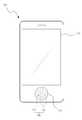
도 1을 참조하면, 본 실시예에 따른 개인휴대단말기(100)는 정면에는 디스플레이(110)가 제공되며, 디스플레이(100) 하부에는 포인팅 영역(120)이 제공될 수 있다. 디스플레이(110)는 그 자체만으로 터치 인식이 가능할 수도 있지만, 다르게는 이미지 디스플레이만 가능하도록 제공될 수도 있다.Referring to FIG. 1, the personal
본 실시예에 따른 개인휴대단말기(100)에서 사용자는 포인팅 영역(120)에 손가락 끝을 올려 놓고 이동시킴으로써 화면의 포인터를 이동시키거나, 화면에서 선택된 메뉴를 이동시키거나, 손가락 이동을 화면의 포인터 이동과 매칭시켜 화면을 통해 원하는 기능을 선택 및 실행할 수가 있다.In the personal
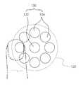
상기 포인팅 영역(120)에는 방사상으로(radially) 배열되는 복수개의 방향전극(134)을 포함하는 방향감지센서(130)가 제공된다. 상기 방향감지센서(130)는 포인팅 영역(120) 내에서의 손가락(또는 스타일러스 펜) 이동을 감지할 수 있으며, 피대상물의 이동에 대응하여 방향감지센서(130)에서 발생하는 신호에 따라 직교좌표정보를 산출하여 방향 감지 기능을 수행할 수 있다.The
상기 방향감지센서(130)의 구조는 요구되는 조건 및 설계 사양에 따라 다양하게 변경될 수 있다. 이하에서는 방향감지센서(130)가 중심전극(132) 및 중심전극(132)을 중심으로 동일한 이격 거리를 갖도록 원주 방향을 따라 등각도로 배열되는 복수개의 방향전극(134)을 포함하여 구성된 예를 들어 설명하기로 한다. 참고로, 상기 중심전극(132) 및 방향전극(134)은 손가락 접촉 면적에 따른 정전용량 변화를 감지할 수 있으며, 도면에는 명확히 도시되어 있지는 않지만 중심전극(132) 및 방향전극(134)은 1:1로 단말기의 제어 칩 또는 포인팅 장치의 마이크로 칩과 연결되어 있다.The structure of the
아울러, 상기 중심전극(132) 및 방향전극(134)은 서로 동일한 크기를 갖는 원형 형상으로 제공될 수 있다. 경우에 따라서는 중심전극 및 방향전극이 서로 다른 크기 및 형상을 갖도록 제공될 수도 있으며, 중심전극 및 방향전극을 비원형, 다각형 또는 여타 다른 기하학적 형상으로 형성하는 것도 가능하다. 이러한 방향전극이 이루는 외형 역시 요구되는 조건 및 설계 사양에 따라 원형, 타원형 또는 다각형 등으로 다양하게 변경될 수 있다. 뿐만 아니라, 복수개의 방향전극이 중심전극을 기준으로 동일 거리상에서 등각도 배열을 이루도록 배치되되, 각각의 방향전극은 서로 다른 형상 및 크기를 갖도록 제공될 수도 있다.In addition, the
참고로, 본 발명의 실시예에서는 중심전극(132)을 중심으로 6개의 방향전극(134)이 방사상으로 배열된 예를 들어 설명하고 있지만, 경우에 따라서는 방향전극의 개수가 더 세분화되어 보다 정밀하게 손가락 이동을 감지할 수 있다. 또한, 중심전극을 기준으로 서로 다른 방사거리(radial distance)를 갖도록 2열 이상의 방향전극이 배치되도록 구성할 수도 있다For reference, in the exemplary embodiment of the present invention, the six
본 발명의 실시예에서는 방향감지센서가 중심전극 및 방향전극을 포함하여 구성된 예를 들어 설명하고 있지만, 경우에 따라서는 별도의 중심전극을 배제하고 방향전극만으로 방향감지센서를 구성할 수도 있다.In the exemplary embodiment of the present invention, the direction sensor is described with an example including the center electrode and the direction electrode. However, in some cases, the direction sensor may be configured with only the direction electrode without the separate center electrode.
다시 도면을 참조하면, 상기 중심전극(132) 및 방향전극(134)은 단순한 전극 구조이기 때문에 종래의 광 포인팅 장치보다는 현저히 저렴한 비용에서 제작될 수가 있다. 본 실시예의 경우, 중심전극(132) 및 방향전극(134)이 케이스 저면에 형성될 수 있지만, 다르게는 플렉시블 회로기판에 형성될 수 있으며, 단말기의 메인 회로기판에 연결되고, 케이스에서는 포인팅 영역의 하부에 위치하도록 장착될 수도 있다. 물론, 이때도 각 방향전극은 플렉시블 회로기판에서 동일 면 또는 상호 반대 면에 형성될 수도 있다.Referring back to the drawings, since the
또한, 경우에 따라서는 포인팅 영역(120)이 버튼 형태로 제공될 수 있는데, 버튼의 내부 또는 표면에 상기 중심전극(132) 및 방향전극(134)들이 형성된 플렉시블 회로기판이 포함되도록 할 수가 있다. 이 경우 사용자는 버튼의 상면 또는 노출된 면 상에서 손가락을 이동시켜 포인팅 장치로 사용할 수 있으며, 다르게는 버튼을 눌러 돔 스위치 등을 작동시킬 수가 있다.In addition, in some cases, the
참고로, 종래의 광 포인팅 장치는 버튼 조작을 위해서 렌즈, 경통, 및 센서 등을 포함하는 포인팅 장치가 전체적으로 움직여야 하지만, 본 실시예에 따른 포인팅 메커니즘은 FPCB 상에 형성하는 것이 가능하고, 버튼에도 적용하는 것이 매우 용이하다.For reference, in the conventional optical pointing device, a pointing device including a lens, a barrel, a sensor, and the like must be moved as a whole to operate a button, but the pointing mechanism according to the present embodiment can be formed on an FPCB, and is also applied to a button. It is very easy to do.
도 2에 도시된 바와 같이, 중심전극(132) 및 방향전극(134)은 손가락의 이동에 의해서 가변되는 전기적 특성의 크기 또는 변화량에 대응하여 전기적 스칼라(물리적 측정량)을 생성할 수 있는 바, 이러한 전기적 스칼라에 따라 직교좌표(rectangular coordinates)정보를 산출할 수 있으며, 이와 같이 산출된 직교좌표정보를 이용하여 방향 감지 기능을 수행할 수 있다. 일 예로, 손가락의 이동에 대응하여 중심전극(132) 및 방향전극(134)에서 손가락과 겹쳐지는 면적에 따라 정전용량이 가변될 수 있으며, 정전용량 변화에 따라 X,Y 좌표(절대직교좌표) 또는 ㅿX,ㅿY 좌표(상대직교좌표) 값을 산출할 수 있다. 다르게는, 손가락의 이동에 대응하여 중심전극 및 방향전극에서 발생하는 신호에 따라, 중심전극을 중심으로 손가락의 위치가 어느 거리(R)만큼 이격되어 있고, 어느 각도(θ)에 위치하는지를 측정할 수 있으며, 측정된 거리 및 각도의 위치 값(R, θ)을 통해 직교좌표정보를 산출할 수도 있다.As shown in FIG. 2, the
이와 같이 산출된 직교좌표정보는 방향감지 기능을 수행하기 위한 회로로 송출될 수 있으며, 상기 회로는 직교좌표정보를 이용하여 방향감지 기능을 수행할 수 있다. 여기서, 방향감지 기능을 수행하기 위한 회로라 함은 단말기의 메인 회로기판에 구비된 회로를 포함할 수 있다.The rectangular coordinate information calculated as described above may be sent to a circuit for performing a direction sensing function, and the circuit may perform a direction sensing function using the rectangular coordinate information. Here, the circuit for performing the direction detection function may include a circuit provided in the main circuit board of the terminal.
또한, 도 3을 참조하면, 손가락이 포인팅 영역(120)의 외부에서 내부로 진입하는 이동을 가정할 수 있다. 예를 들어 손가락은 포인팅 영역(120)의 상하 또는 좌우 4 방향에서 접근할 수 있으며, 이때는 포인팅 영역(120)의 경계에서 손가락의 이동이 감지된 후, 포인팅 영역(120)의 내부에 배치되는 중심전극(132) 또는 방향전극(134)에서 신호가 일정시간 동안 발생할 수가 있다. 이 경우 단말기는 스크롤과 같이 포인팅 장치의 일반적인 방향 감지 외의 다른 기능을 정의할 수가 있다.In addition, referring to FIG. 3, it may be assumed that a finger moves inward from the outside of the
참고로, 본 명세서에서 포인팅 영역의 경계라 함은 복수개의 방향전극 중 최외곽에 배치되는 방향전극의 주변에 정의될 수 있다. 아울러, 본 명세서에서 "방향 감지와 구분되는 별도 기능"이란, 포인팅 장치에서 일반적으로 기대되는 방향 감지 외에 단말기 시스템 또는 특정 프로그램에서 미리 약정된 다른 기능을 의미할 수 있으며, 후술하는 스크롤, 페이지 넘김, 화면 전환, 확대/축소, 클릭 등 다양하게 선택될 수 있으며, 특정 기능의 사용자 정의, 사용자 설정, 기능의 조합 등도 미리 정의할 수가 있다. 이하, 기능을 이해하기 위해 특정 기능을 예로 들어 설명하지만, 손가락의 특정 동작과 그에 대응되는 기능이 반드시 결합되어야 하는 것은 아니다.For reference, the boundary of the pointing area may be defined around the direction electrode disposed at the outermost of the plurality of direction electrodes. In addition, in the present specification, "separate function distinguished from direction detection" may mean other functions previously promised in a terminal system or a specific program in addition to the direction detection generally expected in a pointing device, and may be described below. The screen can be selected in various ways such as screen switching, zooming in and out, and user-defined specific functions, user settings, and combinations of functions can be predefined. Hereinafter, a specific function will be described as an example in order to understand the function, but the specific motion of the finger and the corresponding function are not necessarily combined.
일 예로, 위와 같이 포인팅 영역(120)의 경계에서 손가락의 이동이 감지된 후 중심전극(132) 또는 방향전극(134)으로부터 신호가 감지되는 경우, 손가락의 이동이 감지되는 포인팅 영역(120)의 경계의 위치에 대응하여 상하 또는 좌우 스크롤 중 하나를 선택할 수 있다. 가령, 손가락이 포인팅 영역(120)의 좌측 경계를 통과하여 중심전극(132) 또는 방향전극(134)에서 멈추는 경우, 단말기는 현재 표시된 화면을 우측으로 스크롤 하도록 할 수 있다. 또한, 설정에 따라서 스크롤이 진행되는 경우, 손가락이 중심전극(132) 또는 방향전극(134) 상에 터치 상태로 유지되는 동안 실행되는 스크롤이 계속 유지될 수 있다. 물론, 손가락의 이동이 감지되는 포인트 영역의 경계의 위치에 따라 아래로 위로 혹은 좌우로 스크롤되도록 미리 정의할 수가 있다.For example, if a signal is detected from the
물론, 반대로 손가락이 포인팅 영역(120)의 내부에 있다가 외부로 이동하는 경우에도, 그에 대응되는 별도의 기능이 정의될 수도 있다.Of course, in the case where the finger moves inside the
또한, 도 3에 도시된 바와 같이, 손가락이 포인팅 영역(120)의 외부에서 내부로 이동하면서 스크롤 기능이 활성화된 경우에는, 지속적으로 스크롤 모드가 유지될 수 있고, 사용자의 손가락이 포인팅 영역(120) 내에서 이동하는 경우 스크롤 방향이 추가로 제어되도록 하는 것도 가능하다. 물론, 손가락이 중심전극(132) 또는 방향전극(134)으로부터 떨어져 입력이 일정 시간 지연되는 경우에만 스크롤 모드가 해제되도록 할 수도 있다.In addition, as shown in FIG. 3, when the scroll function is activated while the finger moves from the outside to the inside of the
도 4를 참조하면, 손가락이 포인팅 영역(120)을 횡단 또는 종단하는 경우를 가정할 수 있다. 이 경우 포인팅 영역(120)의 경계 일측에서 손가락의 이동이 감지된 후, 중심전극(132) 또는 방향전극(134)을 통해서 이동이 감지되고, 그 다음 다시 반대편 포인팅 영역(120)의 경계에서 손가락의 이동이 감지될 수 있다. 이때도 역시 단말기는 화면 전환이나 페이지 넘김 등과 같이 직관적으로 이해될 수 있는 별도의 기능을 수행하도록 할 수가 있다.Referring to FIG. 4, it may be assumed that a finger crosses or terminates the
일 예로, 도시된 바와 같이, 포인팅 영역(120)의 좌측 경계에서 손가락의 이동이 감지된 후, 중심전극(132) 또는 방향전극(134)으로부터 신호가 감지되고, 반대편 포인팅 영역(120)의 우측 경계에서 손가락의 이동이 차례대로 감지될 수 있다. 이때 단말기는 현재 활성화된 화면 또는 텍스트의 화면 전환 및 페이지 넘김 중 선택된 기능을 수행하도록 할 수가 있다. 물론, 반대의 경우 반대 방향의 화면 전환이나 페이지 넘김이 정의될 수도 있다.For example, as shown, after the movement of a finger is detected at the left boundary of the
또한, 상술한 바와 같이, 손가락이 경사진 방향 또는 대각선 방향으로 통과하는 경우도 가정할 수 있으며, 이 경우 역시 손가락이 통과되는 포인팅 영역(120)의 경계의 위치에 따라 좌우 클릭이나 확대 축소, 명령 실행이나 취소 등 다양한 기능을 정의할 수가 있다.In addition, as described above, it may be assumed that a finger passes in an inclined direction or a diagonal direction, and in this case, left and right clicks, enlarges and contracts according to the position of the boundary of the
도 5를 참조하면, 손가락이 포인팅 영역(120)의 경계를 따라 선회하는 경우를 가정할 수 있다. 즉, 손가락이 포인팅 영역(120)의 경계를 따라 선회하는 경우 포인팅 영역(120)의 경계에서 포인팅 영역(120)의 경계를 따른 손가락의 이동이 감지될 수 있으며, 이 경우 역시 다양한 기능이 실행될 수 있다.Referring to FIG. 5, it may be assumed that a finger rotates along a boundary of the
일 예로, 포인팅 영역(120)의 경계에서 포인팅 영역(120)의 경계를 따라 손가락의 이동이 순차적으로 감지되는 경우, 단말기에서의 확대/축소의 기능을 수행할 수 있으며, 이미지 또는 웹 화면의 수평 수직 회전, 볼륨의 강약 조절, 재생 속도의 방향 및 빠르기 조절, 동영상의 포워드 및 리워드 조절 등이 다양하게 정의될 수 있다.For example, when the movement of a finger is sequentially sensed along the boundary of the
이 외에도 방향 감지에 따른 상하 조절과 구분하여 가속화될 수 있는 메뉴 이동 등으로 정의될 수 있으며, 일 예로 다수의 곡이 저장된 플레이 리스트에서 원하는 곡을 빠르게 선곡할 때 사용될 수가 있다.In addition, it can be defined as a menu movement that can be accelerated by distinguishing the up and down adjustment according to the direction detection, for example, it can be used to quickly select a desired song from a stored playlist of a plurality of songs.
또한, 본 실시예에 따른 포인팅 장치는 컴퓨터의 마우스와 비슷한 기능을 수행할 수 있으며, 일반적인 컴퓨터 마우스에서 사용하는 PS/2 프로토콜을 이용할 수도 있다.In addition, the pointing device according to the present embodiment may perform a function similar to a mouse of a computer, and may use the PS / 2 protocol used in a general computer mouse.
도 6을 참조하면, 일반 컴퓨터의 마우스에서 작용하는 좌 클릭 및 우 클릭을 적용할 수 있다. 일 예로, 포인팅 영역(120)의 경계에서 소정 시간 동안의 손가락 접촉에 의해서 클릭에 대응하는 동작을 감지할 수 있다. 사용자가 손가락으로 포인팅 영역(120)의 경계를 클릭과 같이 터치하는 경우를 가정할 수 있는데, 이때 단말기는 좌측 또는 우측 포인팅 영역(120)의 경계의 감지 여부에 따라 컴퓨터의 좌측 클릭 및 우측 클릭에 대응하는 명령을 구분할 수 있다. 물론, 위/아래 포인팅 영역(120)의 클릭 역시 이용이 가능하므로, 그 활용도는 컴퓨터의 마우스 이상이 될 수가 있다.Referring to FIG. 6, a left click and a right click acting on a mouse of a general computer may be applied. For example, an operation corresponding to a click may be detected by finger contact for a predetermined time at the boundary of the
또한, 포인팅 영역(120)의 경계를 통한 클릭 신호의 회수에 따라 1회 클릭 또는 더블 클릭 등을 구분할 수 있으며, 이러한 구분을 통해 일반 사용자가 익숙한 컴퓨터 사용환경을 소형 단말기에서도 동일하게 적용할 수가 있다.In addition, one-click or double-click can be distinguished according to the number of click signals through the boundary of the
또한, 포인팅 영역(120)의 경계를 통한 클릭이 일정 시간 지속되는 경우, 짧은 시간 클릭과 구분될 수 있는 다른 기능이 수행될 수 있도록 설계될 수 있으며, 예를 들어 약 1초 이상 클릭의 접촉 상태가 유지되면 복사 등이 가능한 모드로 전환되고, 그 이후 중심전극(132) 또는 방향전극(134)으로 손가락을 이동시켜 복사 영역을 조절하도록 할 수도 있다.In addition, when a click through the boundary of the
전술 및 도시한 본 발명의 실시예에서는 포인팅 영역의 경계에서의 손가락의 이동 감지를 통해 방향 감지와 구분되는 다른 기능을 수행하도록 구성된 예를 들어 설명하고 있지만, 경우에 따라서는 포인팅 영역의 경계에서의 손가락의 이동 감지를 통해 방향전극에 의한 방향 감지 기능도 보조할 수 있다.Although the above-described and illustrated embodiments of the present invention have been described with an example configured to perform other functions distinguished from the direction detection through the detection of movement of a finger at the boundary of the pointing area, in some cases, at the boundary of the pointing area. By detecting the movement of a finger, the direction detection function by the direction electrode can be assisted.
한편, 손가락과 같은 피대상물이 포인팅 영역(120)의 내부에서 이동하는 도중 포인팅 영역(120)의 외부로 벗어나는 것에 대응하여, 방향 감지에 따른 포인터 또는 메뉴 이동 중 포인팅 영역(120)의 경계에서 신호가 감지되는 경우, 중심전극(132) 또는 방향전극(134)에 의한 포인터 또는 메뉴 이동 기능이 전부 또는 부분적으로 제한되도록 프로그램을 조절할 수가 있으며, 방향전극(134)의 바깥 부분에서 발생할 수 있는 오작동을 최소화할 수도 있다.Meanwhile, in response to an object such as a finger moving out of the
도 7 내지 도 11은 본 발명의 다른 실시예에 따른 포인팅 장치의 연성회로기판을 도시한 도면이다. 아울러, 전술한 구성과 동일 및 동일 상당 부분에 대해서는 동일 또는 동일 상당한 참조 부호를 부여하고, 그에 대한 상세한 설명은 생략하기로 한다.7 to 11 illustrate a flexible circuit board of a pointing device according to another embodiment of the present invention. In addition, the same or equivalent portions as those in the above-described configuration are denoted by the same or equivalent reference numerals, and a detailed description thereof will be omitted.
도 7을 참조하면, 원형 형상의 중심전극(232), 및 중심전극(232)을 중심으로 방사상으로 배치되는 원형 형상을 갖는 8개의 방향전극(234)을 포함하는 포인팅 장치의 연성회로기판 구조가 개시되어 있다. 중심전극(232) 및 방향전극(234)들은 우측의 마이크로 칩(10)에 1:1로 전기적으로 연결되며, 통상의 연결 단자들을 통해서 단말기의 메인 회로기판과 연결될 수가 있다.Referring to FIG. 7, a flexible circuit board structure of a pointing device including a
전술 및 도시한 본 발명의 실시예에서는 중심전극을 기준으로 방향전극이 방사 방향을 따라 1열로 배치된 예를 들어 설명하고 있지만, 경우에 따라서는 도 8과 같이, 중심전극(332)을 기준으로 2열 이상의 방향전극(334)이 배치되도록 구성할 수도 있다. 전술한 실시예와 마찬가지로, 중심전극(332) 및 방향전극(334)들은 우측의 마이크로 칩(10)에 1:1로 전기적으로 연결되며, 통상의 연결 단자들을 통해서 단말기의 메인 회로기판과 연결될 수가 있다.In the above-described and illustrated embodiments of the present invention, the direction electrodes are arranged in one row along the radial direction with respect to the center electrode, but in some cases, as shown in FIG. 8, the
아울러, 포인팅 영역이 대략 1㎝ * 1㎝ 이내와 같이 매우 작은 공간으로 제공될 경우, 방향전극은 격자 배열보다 원형 배열(방사상 배열)로 배치되는 것이 유리할 수 있다. 가령, 방향전극이 3*3 격자 배열로 배치될 경우, 중심전극을 기준으로 상하 및 좌우에 배치되는 전극과, 대각선 방향을 따라 배치되는 전극의 이격 거리가 각각 다르기 때문에, 계산이 복잡하고 오차가 발생할 가능성이 있다. 반면, 방향전극이 동일 거리 및 등간격을 갖는 방사상 배열로 배치될 경우, 각 방향전극은 중심전극을 기준으로 모두 동일한 이격 거리를 갖도록 배치될 수 있기 때문에, 복잡한 연산식이 필요치 않고 오차 발생을 최소화할 수 있으며, 손가락의 이동을 보다 효율적으로 감지할 수 있다.In addition, when the pointing area is provided in a very small space such as within about 1 cm * 1 cm, it may be advantageous that the direction electrodes are arranged in a circular arrangement (radial arrangement) rather than a lattice arrangement. For example, when the direction electrodes are arranged in a 3 * 3 lattice arrangement, the distances between the electrodes arranged on the top, bottom, left and right sides of the center electrode and the electrodes arranged along the diagonal direction are different from each other. There is a possibility. On the other hand, when the direction electrodes are arranged in a radial array having the same distance and the same distance, each direction electrode can be arranged to have the same separation distance with respect to the center electrode, so that no complicated calculation formula is required and error occurrence can be minimized. It can detect the movement of the finger more efficiently.
도 9를 참조하면, 국화 형상으로 배열되는 방향전극을 포함하는 포인팅 장치의 구조의 연성회로기판 구조가 개시되어 있다. 방향감지센서(430)는 포인팅 영역(420)의 내부에 배치되는 중심전극(432) 및 중심전극(432)을 중심으로 방사 방향을 따라 등각도로 배열되는 방향전극(434)을 포함하되, 상기 방향전극(434)은 중심전극(432)에 인접한 일단에서 타단으로 갈수록 확장된 크기를 갖도록 제공되어, 상기 중심전극(432)과 함께 대략 국화 형상을 이루도록 배치될 수 있다. 이와 같은 구조에서도 전술한 바와 마찬가지로, 피대상물의 이동에 대응하여 방향감지센서(430)에서 발생하는 신호에 따라 직교좌표정보를 산출하여 방향 감지 기능을 수행할 수 있으며, 포인팅 영역(420)의 경계에서 손가락의 이동이 감지되면 방향 감지와 구분되는 다른 기능을 수행할 수 있다. 아울러, 상기와 같이 국화 형상으로 배열되는 방향전극은 중심전극(432)에 대해 각 방향전극(434)이 보다 인접하게 배치될 수 있는 장점이 있다.Referring to FIG. 9, a flexible circuit board structure having a structure of a pointing device including a direction electrode arranged in a chrysanthemum shape is disclosed. The
또한, 도 7 및 도 9와 같이, 상기 복수개의 전극(중심전극 및 방향전극) 중 손가락의 감지가 이루어지는 전극에 인접한 다른 전극의 연결라인이 전기적으로 차폐시키기 위한 그라운드 전극(236,436)이 제공될 수 있다.In addition, as shown in FIGS. 7 and 9,
즉, 손가락이 특정 전극에 위치하는 경우 해당 전극 또는 그 주변으로 정전용량 등 전기적 특성에 변화를 줄 수 있으며, 이러한 전기적 특성 변화가 손가락의 감지가 이루어지는 전극에 인접한 다른 전극의 연결라인에 영향을 미칠 경우, 손가락 이동의 계산에서 노이즈가 발생될 수 있다. 하지만, 본 발명에서는 그라운드 전극을 이용하여, 특정 전극에서 손가락의 감지가 이루어지는 동안 발생되는 전기적 특성 변화가 인접한 다른 전극의 연결라인에 영향을 미치는 것을 방지할 수 있다.That is, when a finger is located on a specific electrode, it may change electrical characteristics such as capacitance to or around the electrode, and the change in electrical characteristics may affect the connection line of another electrode adjacent to the electrode where the finger is detected. In this case, noise may be generated in the calculation of the finger movement. However, in the present invention, the ground electrode can be used to prevent a change in electrical characteristics generated during the detection of a finger at a specific electrode affecting the connection line of another adjacent electrode.
상기 그라운드 전극(236,436)은 요구되는 조건 및 설계 사양에 따라 다양한 구조로 제공될 수 있다.The
일 예로, 도 7과 같이, 그라운드 전극(236)은 각 방향전극(232,234)의 사이에 평면적으로 제공될 수 있으며, 상기 그라운드 전극(236)에 의해 특정 방향전극(232,234)에서 손가락의 감지가 이루어지는 동안 발생되는 전기적 특성 변화가 인접한 다른 방향전극의 연결라인에 영향을 미치는 것을 방지할 수 있다.For example, as shown in FIG. 7, the
다르게는 도 9와 같이, 그라운드 전극(436)은 각 방향전극(432,334)의 연결라인(434a)이 통과하기 위한 비아홀(436a)을 구비하여 각 방향전극(432,434)의 하부에 제공될 수 있으며, 상기 각 방향전극(432,434)의 연결라인(434a)은 비아홀(436a)을 통과하여 그라운드 전극(436)의 하부에 배치될 수 있다. 이와 같이, 각 방향전극(432,434)의 연결라인(434a)은 그라운드 전극(436)의 하부에 배치되기 때무에, 특정 방향전극(432,434)에서 손가락의 감지가 이루어지는 동안 발생되는 전기적 특성 변화가 인접한 다른 방향전극의 연결라인에 영향을 미치는 것을 더욱 효과적으로 방지할 수 있다.Alternatively, as shown in FIG. 9, the
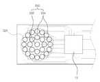
도 10을 참조하면, 버튼과 일체로 제공되는 포인팅 장치의 구조가 개시되어 있다.Referring to FIG. 10, a structure of a pointing device provided integrally with a button is disclosed.
도 10과 같이, 포인팅 영역(520)이 버튼 형태로 제공되는 경우, 버튼(552,554)의 내부 또는 표면에는 중심전극(532) 및 방향전극(534)이 형성된 연성회로기판(542)이 장착될 수 있으며, 이는 광포인팅 장치에 비해 현저히 간단하면서 효율적인 구조를 제공할 수 있다.As shown in FIG. 10, when the
또한, 기존의 버튼(552,554)에서 전혀 구조적인 변화가 없기 때문에 내구성에 있어서도 문제가 발행하지 않으며, 기존 버튼(552,554)에서 사용자는 버튼(552,554)의 상면 또는 노출된 면 상에서 손가락을 이동시켜 포인팅 장치로 사용하는 것이 가능하다. 물론, 아래로는 버튼(552,554)을 눌러 돔 스위치(560) 등을 작동시킬 수가 있다.In addition, since there is no structural change at all in the existing
전술한 실시예와 마찬가지로, 중심전극(532) 및 방향전극(534)은 각각 마이크로 칩(542)과 일대일로 연결되어 있으며, 마이크로 칩(542)을 통해 버튼(552,554) 상의 손가락 움직임은 직교좌표정보로 산출될 수 있으며, 마이크로 칩(542)에서 계산된 직교좌표정보는 메인회로기판으로 전달될 수 있다.As in the above-described embodiment, the
본 발명의 실시예에서는 버튼이 평면적으로 형성된 예를 들어 설명하고 있지만, 경우에 따라서는 버튼을 곡면으로 처리함으로써 버튼의 위치를 구조적으로 한정할 수 있으며, 손가락이 용이하게 움직이도록 버튼의 상면을 오목하게 형성할 수도 있다.In the exemplary embodiment of the present invention, a button is formed in a planar manner, but in some cases, the button may be curved to be structurally defined, and the upper surface of the button may be concave so that the finger moves easily. It can also be formed.
도 11을 참조하면, 하부전극층(634)을 포함하는 포인팅 장치의 연성회로기판 구조가 개시되어 있다.Referring to FIG. 11, a flexible circuit board structure of a pointing device including a
도 11과 같이, 본 실시예에 따른 개인휴대단말기는 기판(640) 상에서 포인팅 영역(620)을 제공하며, 손가락에 이동에 대응하여 방향감지센서(630)에서 발생하는 신호에 따라 직교좌표정보를 산출하여 방향 감지 기능을 수행할 수 있으며, 포인팅 영역(620)의 경계에서 손가락의 이동이 감지되면 방향 감지와 구분되는 다른 기능을 수행할 수 있다.As shown in FIG. 11, the personal handheld terminal according to the present exemplary embodiment provides a
방향감지센서(630)는 평면적으로 포인팅 영역(620) 내에 배치되는 방향전극(632), 및 상기 방향전극(632)과 전기적으로 분리되며 방향전극(632)의 하부에 위치하는 하부전극층(634)을 포함하여 구성될 수 있다.The
상기 하부전극층(634)은 기판(640)의 저면에 형성되며, 외부로부터 전달되는 펄스 신호를 전면적으로 발생시킬 수 있다. 손가락이 특정 방향전극(632,634)에 위치하는 경우 그 방향전극 또는 그 주변으로 정전용량 등 전기적 특성에 변화를 줄 수 있으며, 이때 다른 방향전극에 비해 변화된 펄스 신호를 수신하게 된다. 이러한 특성을 이용하여 포인팅 장치는 피대상물의 이동을 감지할 수가 있다.The
이러한 적층구조 역시 전술한 실시예에서 설명된 방향전극 구조보다는 다소 복잡하지만, 방향 감지와 구분될 수 있는 별도의 기능, 예를 들어 스크롤, 화면 전환, 페이지 넘김, 회전, 확대/축소, 속도나 볼륨 조절 등 다양한 기능을 수행할 수 있다.This stacking structure is also somewhat more complicated than the direction electrode structure described in the above embodiments, but can be distinguished from direction detection, for example, scrolling, screen switching, page turning, rotation, zooming, speed or volume. Various functions such as adjustment can be performed.
물론, 여기서도 방향전극(632)은 단말기의 제어 칩 또는 포인팅 장치의 마이크로 칩과 1:1로 연결되어 있으며, 하부전극층(634)은 하나의 넓은 전극으로서 단말기의 제어 칩 또는 포인팅 장치의 마이크로 칩과 연결되어 있다.Of course, the
도 12는 본 발명의 또 다른 실시예에 따른 포인팅 장치의 방향감지센서의 구조를 설명하기 위한 도면이다. 아울러, 전술한 구성과 동일 및 동일 상당 부분에 대해서는 동일 또는 동일 상당한 참조 부호를 부여하고, 그에 대한 상세한 설명은 생략하기로 한다.12 is a view for explaining the structure of the direction sensor of the pointing device according to another embodiment of the present invention. In addition, the same or equivalent portions as those in the above-described configuration are denoted by the same or equivalent reference numerals, and a detailed description thereof will be omitted.
도 12를 참조하면, 본 발명의 또 다른 실시예에 따르면, 포인팅 영역(720)의 경계를 따라 제공되는 테두리 전극(736)을 더 포함할 수 있으며, 피대상물의 이동에 대응하여 테두리 전극(736)으로부터 신호가 감지되는 경우, 방향감지와 구분되는 별도 기능을 수행할 수 있다.Referring to FIG. 12, according to another embodiment of the present disclosure, the
테두리 전극(736)은 포인팅 영역(720)의 테두리 또는 그에 인접하게 제공될 수 있으며, 링(ring)과 같이 연속적으로 연결된 형태 또는 부분적으로 끊어져서 독립적으로 칩과 연결된 형태로 제공될 수가 있다. 본 실시예에서는 4개로 분리된 테두리 전극(736)이 적용된 예를 들어 설명하기로 한다. 아울러, 중심전극(732) 및 방향전극(734)은 평면적으로 테두리 전극(736)의 정의되는 영역 내에 배치될 수 있다.The
테두리 전극(736)을 이용하는 경우, 보다 분명한 제어가 가능하다. 예를 들어, 포인팅 영역(720) 내에서의 이동에 따라 포인터 및 메뉴를 이동시키는 것 외에도, 포인팅 영역(720)의 경계를 통과하는 경우, 즉 손가락이 포인팅 영역(720) 밖에 있다가 안으로 들어오는 경우 방향에 따라 상하 좌우 스크롤(scroll)로 사용할 수 있으며, 테두리 전극(736), 방향전극(732,734) 및 테두리 전극(736)에서 차례로 감지되는 경우와 같이 포인팅 영역(720)을 횡단 또는 종단하여 완전히 통과하는 경우 방향에 따라 화면 전환이나 페이지 넘김 등으로 사용할 수가 있다. 또한, 테두리 전극(736)을 따라 손가락이 선회하면서 이동하는 경우 이미지나 텍스트 확대/축소 등의 임의로 설정 가능한 다양한 기능을 수행하도록 제어할 수도 있다. 또한, 좌우 테두리 전극(736)을 가볍게 터치하는 것에 대응하여 컴퓨터 마우스의 좌우 클릭 및 더블 클릭 등에 대응하여 반응하도록 할 수도 있다.When the
한편, 방향전극(732,734)에서의 신호가 테두리 전극(736)에서의 신호보다 높게 감지되는 경우, 즉 방향전극(732,734)을 이용한 방향 감지 또는 내비게이션을 수행하고자 하는 경우, 단말기는 방향감지 모드 또는 내비게이션 모드를 활성화 시킬 수 있다. 이 경우, 일정 시간(예를 들어, 약 1초) 이상 방향전극(732,734)에서의 감지가 끊기지 않는 한, 테두리 전극(736) 감지에 의한 다른 기능 수행을 제한하고 방향 감지에 의한 포인터 이동이나 메뉴 이동만 가능하게 할 수도 있다. 이로써 내비게이션 이동을 위한 손가락 움직임이 일시적으로 포인팅 영역(720)의 테두리를 벗어나더라도 방향 감지 이외의 기능이 작동을 시작하지 않고 지속적으로 방향 감지에 의한 내비게이션 모드가 진행되도록 할 수가 있다. 물론, 손가락이 일정 시간 이상 떨어져서 내비게이션 모드가 해제된 경우에는 다시 포인팅 영역(720)의 테두리에서 감지되는 정보에 따라 스크롤, 화면 넘기기, 확대 등의 다른 기능 등이 수행되도록 할 수가 있다.On the other hand, when a signal from the
상술한 바와 같이, 본 발명의 바람직한 실시예들을 참조하여 설명하였지만 해당 기술분야의 숙련된 당업자라면 하기의 청구범위에 기재된 본 발명의 기술적 개념에서 벗어나지 않는 범위 내에서 본 발명을 다양하게 수정 및 변경시킬 수 있음을 이해할 수 있을 것이다.While the present invention has been described with reference to exemplary embodiments thereof, it will be understood by those skilled in the art that various changes in form and details may be made therein without departing from the spirit and scope of the invention as defined by the appended claims. It can be understood that it is possible.
100 : 개인휴대단말기 110 : 디스플레이
120 : 포인팅 영역 130 : 방향감지센서
132 : 중심전극 134 : 방향전극100 : Personal mobile device 110 : Display
120: pointing area 130: direction detecting sensor
132: center electrode 134: direction electrode
Claims (28)
Translated fromKorean상기 포인팅 영역 내에 방사상으로 배열되는 복수개의 방향전극을 포함하는 방향감지센서를 제공하는 단계;
상기 피대상물의 이동에 대응하여 상기 방향감지센서에서 발생하는 신호에 따라 직교좌표(rectangular coordinates)정보를 산출하는 단계; 및
상기 직교좌표정보를 이용하여 방향 감지 기능을 수행하는 단계;
를 포함하는 단말기 제어방법.In the method for controlling the terminal in response to the movement of the object on the pointing area,
Providing a direction detecting sensor including a plurality of direction electrodes arranged radially in the pointing area;
Calculating rectangular coordinates information according to a signal generated from the direction sensor in response to the movement of the object; And
Performing a direction sensing function using the rectangular coordinate information;
Terminal control method comprising a.
상기 직교좌표정보는 절대직교좌표 및 상대직교좌표 중 적어도 어느 하나를 포함하는 것을 특징으로 하는 단말기 제어방법.The method of claim 1,
The Cartesian coordinate information terminal control method characterized in that it comprises at least one of absolute rectangular coordinates and relative rectangular coordinates.
상기 방향감지센서는 중심전극을 더 포함하고,
상기 방향전극은 상기 중심전극을 중심으로 원주 방향을 따라 배열되는 것을 특징으로 하는 단말기 제어방법.The method of claim 1,
The direction sensor further includes a center electrode,
The direction electrode is a terminal control method, characterized in that arranged in the circumferential direction around the center electrode.
상기 방향전극은 상기 중심전극에 대해 동일한 이격 거리를 가지며, 상기 중심전극을 중심으로 등각도로 배열된 것을 특징으로 하는 단말기 제어방법.The method of claim 3,
The direction electrode has the same separation distance with respect to the center electrode, characterized in that arranged in an equiangular center around the center electrode.
산출된 상기 직교좌표정보를 방향감지 기능을 수행하기 위한 회로로 송출하는 단계를 더 포함하는 것을 특징으로 하는 단말기 제어방법.The method of claim 1,
And transmitting the calculated Cartesian coordinate information to a circuit for performing a direction sensing function.
상기 포인팅 영역의 경계에서 피대상물의 이동이 감지됨에 따라 발생하는 신호에 대응하여 상기 방향 감지와 구분되는 다른 기능을 수행하는 것을 특징으로 하는 단말기 제어방법.The method of claim 1,
And controlling other functions different from the direction detection in response to a signal generated as the movement of the object is detected at the boundary of the pointing area.
상기 포인팅 영역의 경계는 상기 복수개의 방향전극 중 최외곽에 배치되는 방향전극의 주변에 정의되는 것을 특징으로 하는 단말기 제어방법.The method of claim 6,
And a boundary of the pointing area is defined around a direction electrode disposed on the outermost side of the plurality of direction electrodes.
상기 피대상물이 상기 포인팅 영역의 외부에서 내부로 진입하는 것에 대응하여, 상기 포인팅 영역의 경계에서 상기 피대상물의 이동이 감지되면, 상기 방향 감지와 구분되는 별도 기능을 수행하는 것을 특징으로 하는 단말기 제어방법.The method of claim 6,
In response to the object entering from the outside of the pointing area to the inside, when the movement of the object is detected at the boundary of the pointing area, the terminal control characterized in that it performs a separate function distinct from the direction detection Way.
상기 피대상물이 상기 포인팅 영역의 경계를 따라 선회하는 것에 대응하여, 상기 포인팅 영역의 경계를 따른 상기 피대상물의 이동이 감지되는 경우, 상기 방향 감지와 구분되는 별도 기능을 수행하는 것을 특징으로 하는 단말기 제어방법.The method of claim 6,
And in response to the object turning along the boundary of the pointing area, when the movement of the object along the boundary of the pointing area is detected, the terminal performs a separate function distinct from the direction detection. Control method.
상기 피대상물이 상기 포인팅 영역의 경계를 클릭과 같이 터치하는 것에 대응하여, 상기 포인팅 영역의 경계에서 상기 피대상물의 이동이 감지됨에 따른 신호가 1회 또는 그 이상 단속적으로 감지되는 경우, 상기 방향 감지와 구분되는 별도 기능을 수행하는 것을 특징으로 하는 단말기 제어방법.The method of claim 6,
In response to the object touching the boundary of the pointing area as a click, when the signal of the movement of the object is detected at the boundary of the pointing area is intermittently detected one or more times, detecting the direction Terminal control method characterized in that performing a separate function distinguished from.
상기 포인팅 영역의 경계를 따라 제공되는 테두리 전극을 더 포함하고,
상기 피대상물의 이동에 대응하여 상기 테두리 전극으로부터 신호가 감지되는 경우, 상기 방향감지와 구분되는 별도 기능을 수행하는 것을 특징으로 하는 단말기 제어방법.The method of claim 1,
And an edge electrode provided along a boundary of the pointing area,
And detecting a signal from the edge electrode in response to the movement of the object, performing a separate function distinct from the direction detection.
상기 방향감지센서는 상기 방향전극과 전기적으로 분리되며 상기 방향전극의 하부에 위치하는 하부전극층을 더 포함하며,
상기 하부전극층으로부터 전달되는 펄스 신호 및 상기 펄스 신호에 대응하여 상기 방향전극에서 감지되는 신호를 이용하여 상기 피대상물의 이동 방향을 감지하는 것을 특징으로 하는 단말기 제어방법.The method of claim 1,
The direction sensor further includes a lower electrode layer electrically separated from the direction electrode and positioned below the direction electrode,
And a direction of movement of the object by using a pulse signal transmitted from the lower electrode layer and a signal detected by the direction electrode in response to the pulse signal.
상기 복수개의 방향전극 중 상기 피대상물의 감지가 이루어지는 방향전극에 인접한 다른 방향전극의 연결라인을 전기적으로 차폐하는 그라운드 전극을 더 포함하는 것을 특징으로 하는 단말기 제어방법.The method of claim 1,
And a ground electrode electrically shielding a connection line of another directional electrode adjacent to the directional electrode on which the object is detected, among the plurality of directional electrodes.
상기 그라운드 전극은 상기 각 방향전극의 사이에 평면적으로 제공되는 것을 특징으로 하는 단말기 제어방법.The method of claim 13,
The ground electrode is a terminal control method, characterized in that provided in the plane between each direction electrode.
상기 그라운드 전극은 상기 각 방향전극의 연결라인이 통과하기 위한 비아홀을 구비하여 상기 각 방향전극의 하부에 제공되며,
상기 각 방향전극의 연결라인은 상기 비아홀을 통과하여 상기 그라운드 전극의 하부에 배치되는 것을 특징으로 하는 단말기 제어방법.The method of claim 13,
The ground electrode has a via hole through which a connection line of each direction electrode passes, and is provided below the direction electrode.
And a connection line of each of the directional electrodes is disposed under the ground electrode through the via hole.
방사상으로 배열되는 복수개의 방향전극을 포함하여 상기 포인팅 영역 내에 배치되는 방향감지센서를 포함하고,
상기 피대상물의 이동에 대응하여 상기 방향감지센서에서 발생하는 신호에 따라 산출되는 직교좌표정보를 이용하여 방향 감지 기능을 수행할 수 있는 것을 특징으로 하는 포인팅 장치.In the pointing device for detecting the movement of the object on the pointing area,
And a direction detecting sensor disposed in the pointing area including a plurality of direction electrodes arranged radially,
And a direction sensing function by using rectangular coordinate information calculated according to a signal generated by the direction sensor in response to the movement of the object.
상기 복수개의 방향전극은 동일 기판 상에 제공되는 것을 특징으로 하는 포인팅 장치.The method of claim 16,
And the plurality of directional electrodes are provided on the same substrate.
상기 복수개의 방향전극은 누름 가능한 버튼 내부에 제공되는 것을 특징으로 하는 포인팅 장치.The method of claim 16,
And the plurality of direction electrodes are provided inside a pushable button.
상기 방향전극은 상기 포인팅 영역의 형상에 따라 원형, 타원형 또는 다각형 중 어느 하나의 외형을 갖도록 제공되는 것을 특징으로 하는 포인팅 장치.The method of claim 16,
The direction electrode is a pointing device, characterized in that provided with a shape of any one of the circular, oval or polygonal according to the shape of the pointing area.
상기 방향감지센서는 중심전극을 더 포함하고,
상기 방향전극은 상기 중심전극을 중심으로 원주 방향을 따라 배열되는 것을 특징으로 포인팅 장치.The method of claim 16,
The direction sensor further includes a center electrode,
And the direction electrodes are arranged along the circumferential direction with respect to the center electrode.
상기 방향감지센서는 상기 방향전극과 전기적으로 분리되며 상기 방향전극의 하부에 위치하는 하부전극층을 더 포함하며,
상기 하부전극층으로부터 전달되는 펄스 신호 및 상기 펄스 신호에 대응하여 상기 방향전극에서 감지되는 신호를 이용하여 상기 피대상물의 이동 방향을 감지하는 것을 특징으로 하는 포인팅 장치.The method of claim 16,
The direction sensor further includes a lower electrode layer electrically separated from the direction electrode and positioned below the direction electrode,
And a direction of movement of the object by using a pulse signal transmitted from the lower electrode layer and a signal detected by the direction electrode in response to the pulse signal.
상기 포인팅 영역의 경계에서 상기 피대상물의 이동이 감지됨에 따라 발생하는 신호에 대응하여 방향 감지와 구분되는 다른 기능을 수행할 수 있는 것을 특징으로 하는 포인팅 장치.The method of claim 16,
And a function different from direction detection in response to a signal generated as the movement of the object is detected at the boundary of the pointing area.
상기 포인팅 영역의 경계를 따라 제공되는 테두리 전극을 더 포함하고,
상기 피대상물의 이동에 대응하여 상기 테두리 전극으로부터 감지되는 정보를 이용하여 상기 방향감지와 구분되는 별도 기능을 수행할 수 있는 것을 특징으로 하는 포인팅 장치.The method of claim 16,
And an edge electrode provided along a boundary of the pointing area,
And a separate function distinguishing from the direction detection by using information detected from the edge electrode in response to the movement of the object.
상기 테두리 전극은 상기 포인팅 영역의 경계를 따라 연속적인 일체로 또는 불연속적인 복수개로 제공되는 것을 특징으로 하는 포인팅 장치.The method of claim 23, wherein
And the edge electrode is provided in a plurality of continuously integrally or discontinuously along the boundary of the pointing area.
상기 복수개의 방향전극 중 상기 피대상물의 감지가 이루어지는 방향전극에 인접한 다른 방향전극의 연결라인을 전기적으로 차폐하는 그라운드 전극을 더 포함하는 것을 특징으로 하는 포인팅 장치.The method of claim 16,
And a ground electrode electrically shielding a connection line of another direction electrode adjacent to the direction electrode on which the object is detected, from among the plurality of direction electrodes.
상기 그라운드 전극은 상기 각 방향전극의 사이에 평면적으로 제공되는 것을 특징으로 하는 포인팅 장치.26. The method of claim 25,
And the ground electrode is planarly provided between the respective directional electrodes.
상기 그라운드 전극은 상기 각 방향전극의 연결라인이 통과하기 위한 비아홀을 구비하여 상기 각 방향전극의 하부에 제공되며,
상기 각 방향전극의 연결라인은 상기 비아홀을 통과하여 상기 그라운드 전극의 하부에 배치되는 것을 특징으로 하는 포인팅 장치.26. The method of claim 25,
The ground electrode has a via hole through which a connection line of each direction electrode passes, and is provided below the direction electrode.
And a connecting line of each of the directional electrodes is disposed under the ground electrode through the via hole.
상기 복수개의 방향전극이 형성된 연성회로기판; 및
상기 연성회로기판에 장착되어 상기 복수개의 방향전극으로부터 감지되는 신호에 따라 독립된 명령 신호를 생성하는 방향 감지용 칩;을 더 포함하는 것을 특징으로 하는 포인팅 장치.The method of claim 16,
A flexible circuit board on which the plurality of directional electrodes are formed; And
And a direction sensing chip mounted on the flexible circuit board to generate an independent command signal according to the signals sensed by the plurality of direction electrodes.
Priority Applications (1)
| Application Number | Priority Date | Filing Date | Title |
|---|---|---|---|
| KR1020110000206AKR20120078906A (en) | 2011-01-03 | 2011-01-03 | Method of controlling terminal device and pointing device |
Applications Claiming Priority (1)
| Application Number | Priority Date | Filing Date | Title |
|---|---|---|---|
| KR1020110000206AKR20120078906A (en) | 2011-01-03 | 2011-01-03 | Method of controlling terminal device and pointing device |
Publications (1)
| Publication Number | Publication Date |
|---|---|
| KR20120078906Atrue KR20120078906A (en) | 2012-07-11 |
Family
ID=46712096
Family Applications (1)
| Application Number | Title | Priority Date | Filing Date |
|---|---|---|---|
| KR1020110000206ACeasedKR20120078906A (en) | 2011-01-03 | 2011-01-03 | Method of controlling terminal device and pointing device |
Country Status (1)
| Country | Link |
|---|---|
| KR (1) | KR20120078906A (en) |
- 2011
- 2011-01-03KRKR1020110000206Apatent/KR20120078906A/ennot_activeCeased
Similar Documents
| Publication | Publication Date | Title |
|---|---|---|
| KR101114873B1 (en) | Movement sensing device and movement sensing method using proximity sensor | |
| KR102446706B1 (en) | Electronic devices with complex human interfaces | |
| US20220391086A1 (en) | Selective rejection of touch contacts in an edge region of a touch surface | |
| US8169418B2 (en) | Displays for electronic devices that detect and respond to the size and/or angular orientation of user input objects | |
| CN103154869B (en) | Display for an electronic device that detects and responds to user input of an object's shape and/or height profile | |
| US20140043265A1 (en) | System and method for detecting and interpreting on and off-screen gestures | |
| US20100123665A1 (en) | Displays for Mobile Devices that Detect User Inputs Using Touch and Tracking of User Input Objects | |
| EP2439623B1 (en) | Information processing apparatus including a sensing unit on a side surface and corresponding method | |
| KR101749956B1 (en) | Computer keyboard with integrated an electrode arrangement | |
| KR101149980B1 (en) | Touch sensor for a display screen of an electronic device | |
| KR20170124068A (en) | Electrical device having multi-functional human interface | |
| US20160026304A1 (en) | Hand-Held Electronic Device and Touch-Sensing Cover Thereof | |
| KR102502603B1 (en) | Electronic device having multi functional human interface and method for controlling the same | |
| KR20120078906A (en) | Method of controlling terminal device and pointing device | |
| KR20120071930A (en) | Terminal control method and pointing device | |
| KR20120057747A (en) | Method of controlling pointing device of terminal device and poingting device using roundly arranged electrodes | |
| KR20120022378A (en) | Method of controlling terminal device and poingting device using boundary electrode | |
| KR20120080006A (en) | Pointing device | |
| KR101397164B1 (en) | Pointing device | |
| KR20190025471A (en) | Electronic device having multi functional human interface and method for controlling the same | |
| KR20190025470A (en) | Electronic device having multi functional human interface and method for controlling the same |
Legal Events
| Date | Code | Title | Description |
|---|---|---|---|
| PA0109 | Patent application | Patent event code:PA01091R01D Comment text:Patent Application Patent event date:20110103 | |
| N231 | Notification of change of applicant | ||
| PN2301 | Change of applicant | Patent event date:20110422 Comment text:Notification of Change of Applicant Patent event code:PN23011R01D | |
| A201 | Request for examination | ||
| PA0201 | Request for examination | Patent event code:PA02012R01D Patent event date:20110512 Comment text:Request for Examination of Application Patent event code:PA02011R01I Patent event date:20110103 Comment text:Patent Application | |
| E902 | Notification of reason for refusal | ||
| PE0902 | Notice of grounds for rejection | Comment text:Notification of reason for refusal Patent event date:20120625 Patent event code:PE09021S01D | |
| PG1501 | Laying open of application | ||
| E601 | Decision to refuse application | ||
| PE0601 | Decision on rejection of patent | Patent event date:20121010 Comment text:Decision to Refuse Application Patent event code:PE06012S01D Patent event date:20120625 Comment text:Notification of reason for refusal Patent event code:PE06011S01I |