KR20120078529A - Piezoelectric actuator - Google Patents
Piezoelectric actuatorDownload PDFInfo
- Publication number
- KR20120078529A KR20120078529AKR1020110004032AKR20110004032AKR20120078529AKR 20120078529 AKR20120078529 AKR 20120078529AKR 1020110004032 AKR1020110004032 AKR 1020110004032AKR 20110004032 AKR20110004032 AKR 20110004032AKR 20120078529 AKR20120078529 AKR 20120078529A
- Authority
- KR
- South Korea
- Prior art keywords
- electrode pattern
- piezoelectric
- piezoelectric sheet
- electrode
- piezoelectric actuator
- Prior art date
- Legal status (The legal status is an assumption and is not a legal conclusion. Google has not performed a legal analysis and makes no representation as to the accuracy of the status listed.)
- Withdrawn
Links
- 238000000034methodMethods0.000claimsdescription26
- UONOETXJSWQNOL-UHFFFAOYSA-Ntungsten carbideChemical compound[W+]#[C-]UONOETXJSWQNOL-UHFFFAOYSA-N0.000claimsdescription10
- 229910010293ceramic materialInorganic materials0.000claimsdescription6
- 229910018072Al 2 O 3Inorganic materials0.000claimsdescription5
- 229910000997High-speed steelInorganic materials0.000claimsdescription5
- 229910001315Tool steelInorganic materials0.000claimsdescription5
- 238000004519manufacturing processMethods0.000abstractdescription5
- 230000008901benefitEffects0.000description5
- 230000008602contractionEffects0.000description5
- 238000013519translationMethods0.000description4
- 238000005452bendingMethods0.000description3
- 238000010586diagramMethods0.000description3
- 239000000463materialSubstances0.000description3
- 230000004048modificationEffects0.000description3
- 238000012986modificationMethods0.000description3
- 239000007767bonding agentSubstances0.000description2
- 230000000694effectsEffects0.000description2
- ATJFFYVFTNAWJD-UHFFFAOYSA-NTinChemical compound[Sn]ATJFFYVFTNAWJD-UHFFFAOYSA-N0.000description1
- 230000002457bidirectional effectEffects0.000description1
- 238000010276constructionMethods0.000description1
- 238000013461designMethods0.000description1
- 239000007769metal materialSubstances0.000description1
- 230000004044responseEffects0.000description1
- 238000000926separation methodMethods0.000description1
- 239000002356single layerSubstances0.000description1
- 239000003381stabilizerSubstances0.000description1
Images


Classifications
- H—ELECTRICITY
- H02—GENERATION; CONVERSION OR DISTRIBUTION OF ELECTRIC POWER
- H02N—ELECTRIC MACHINES NOT OTHERWISE PROVIDED FOR
- H02N2/00—Electric machines in general using piezoelectric effect, electrostriction or magnetostriction
- H02N2/02—Electric machines in general using piezoelectric effect, electrostriction or magnetostriction producing linear motion, e.g. actuators; Linear positioners ; Linear motors
- H—ELECTRICITY
- H02—GENERATION; CONVERSION OR DISTRIBUTION OF ELECTRIC POWER
- H02N—ELECTRIC MACHINES NOT OTHERWISE PROVIDED FOR
- H02N2/00—Electric machines in general using piezoelectric effect, electrostriction or magnetostriction
- H02N2/0005—Electric machines in general using piezoelectric effect, electrostriction or magnetostriction producing non-specific motion; Details common to machines covered by H02N2/02 - H02N2/16
- H02N2/005—Mechanical details, e.g. housings
- H02N2/0065—Friction interface
- H—ELECTRICITY
- H10—SEMICONDUCTOR DEVICES; ELECTRIC SOLID-STATE DEVICES NOT OTHERWISE PROVIDED FOR
- H10N—ELECTRIC SOLID-STATE DEVICES NOT OTHERWISE PROVIDED FOR
- H10N30/00—Piezoelectric or electrostrictive devices
- H10N30/01—Manufacture or treatment
- H10N30/06—Forming electrodes or interconnections, e.g. leads or terminals
- H10N30/063—Forming interconnections, e.g. connection electrodes of multilayered piezoelectric or electrostrictive parts
- H—ELECTRICITY
- H10—SEMICONDUCTOR DEVICES; ELECTRIC SOLID-STATE DEVICES NOT OTHERWISE PROVIDED FOR
- H10N—ELECTRIC SOLID-STATE DEVICES NOT OTHERWISE PROVIDED FOR
- H10N30/00—Piezoelectric or electrostrictive devices
- H10N30/50—Piezoelectric or electrostrictive devices having a stacked or multilayer structure
- H—ELECTRICITY
- H10—SEMICONDUCTOR DEVICES; ELECTRIC SOLID-STATE DEVICES NOT OTHERWISE PROVIDED FOR
- H10N—ELECTRIC SOLID-STATE DEVICES NOT OTHERWISE PROVIDED FOR
- H10N30/00—Piezoelectric or electrostrictive devices
- H10N30/80—Constructional details
- H10N30/87—Electrodes or interconnections, e.g. leads or terminals
- H10N30/872—Interconnections, e.g. connection electrodes of multilayer piezoelectric or electrostrictive devices
Landscapes
- Engineering & Computer Science (AREA)
- Manufacturing & Machinery (AREA)
- General Electrical Machinery Utilizing Piezoelectricity, Electrostriction Or Magnetostriction (AREA)
Abstract
Translated fromKoreanDescription
Translated fromKorean본 발명은 압전 액츄에이터에 관한 것이다.
The present invention relates to piezoelectric actuators.
최근 전자기 모터를 대신하는 새로운 모터로서 압전체를 이용한 압전 액츄에이터가 주목받고 있다. 압전 액츄에이터는 압전시트에 미세한 진폭을 발생시키고, 압전시트에 부착된 마찰부재와 로터(또는 슬라이더)의 접촉 마찰을 이용하여 이러한 미세 진동을 로터 등의 피마찰부재에 전달함으로써, 피마찰부재의 왕복 진동을 가능하게 한다. 이러한 압전모터는 종래의 전자기 모터에 비하여 에너지 밀도가 높고 응답속도가 빠르며, 소음이 적다는 등의 이점이 있다.
Recently, a piezoelectric actuator using a piezoelectric body has attracted attention as a new motor replacing an electromagnetic motor. The piezoelectric actuator generates minute amplitudes in the piezoelectric sheet and transfers these minute vibrations to the frictional member such as the rotor by using contact friction between the friction member attached to the piezoelectric sheet and the rotor (or slider), thereby reciprocating the frictional member. Enable vibration Such piezoelectric motors have advantages such as higher energy density, faster response speed, and lower noise than conventional electromagnetic motors.
종래의 압전 액츄에이터는 수직 방향의 진동 운동 및 수평 방향의 진동 운동을 병합함으로써 전체적으로 타원 궤적을 그리며 진동하는 압전체에 관한 것이었다.Conventional piezoelectric actuators have been directed to piezoelectric elements which vibrate in an elliptic trajectory as a whole by merging vertical and horizontal vibrations.
종래 기술에 따른 압전 액츄에이터는, 타원 궤적을 갖는 압전체를 구현하기 위해 진동 방향이 다른 압전시트를 2개 이상 적층하여야 하고, 각각의 압전시트에는 각각 수직 방향의 진동 출력을 낼 수 있는 전극패턴 및 수평 방향의 진동 출력을 낼 수 있는 전극패턴을 형성하여야 했다. 또한, 이에 따라 각각의 전극패턴에 인가되는 전기신호의 설정 방식이 복잡하다는 문제점이 있었다.In the piezoelectric actuator according to the prior art, two or more piezoelectric sheets having different vibration directions should be stacked in order to realize a piezoelectric body having an elliptic trajectory, and each piezoelectric sheet has an electrode pattern capable of generating a vibration output in the vertical direction and a horizontal direction. It was necessary to form an electrode pattern capable of producing a vibration output in the direction. In addition, there is a problem in that the electric signal setting method applied to each electrode pattern is complicated.
더 나아가, 복잡한 전극패턴이 형성되어 복잡한 구조를 갖는 압전 액츄에이터를 구동시키기 위해, 전압 인가 방식을 설계하는데 다소 오랜 시간이 소요되었으며, 이에 따라 압전 액츄에이터의 제작 시간 및 제조 비용이 증가하는 문제점이 있었다.Furthermore, in order to drive a piezoelectric actuator having a complicated structure by forming a complicated electrode pattern, it took a long time to design a voltage application method, which increases the manufacturing time and manufacturing cost of the piezoelectric actuator.
뿐만 아니라, 압전 액츄에이터의 구조가 복잡해짐에 따라, 압전 액츄에이터가 채용되는 전자제품은 그 크기가 필요 이상으로 비대해지는 문제점이 있었다.
In addition, as the structure of the piezoelectric actuator becomes complicated, electronic products employing the piezoelectric actuators have a problem in that their size becomes larger than necessary.
본 발명은 상기와 같은 문제점을 해결하기 위해 안출된 것으로서, 본 발명의 목적은 압전 액츄에이터를 구성하는 전극패턴을 단순화함으로써 압전 액츄에이터의 제조비용을 절감하고, 압전 액츄에이터의 평면 단순 병진 운동만을 이용함으로써 압전 액츄에이터 자체 또는 압전 액츄에이터가 채용되는 전자제품의 크기를 소형화 가능하며, 평면상의 두 방향으로 독립적으로 병진 운동이 가능한 압전 액츄에이터를 제공하기 위한 것이다.
The present invention has been made to solve the above problems, an object of the present invention is to reduce the manufacturing cost of the piezoelectric actuator by simplifying the electrode pattern constituting the piezoelectric actuator, piezoelectric by using only the planar simple translational motion of the piezoelectric actuator The present invention provides a piezoelectric actuator capable of miniaturizing the size of an electronic product in which an actuator itself or a piezoelectric actuator is employed, and independently translating in two directions on a plane.
본 발명의 바람직한 제1 실시예에 따른 압전 액츄에이터는, 압전시트, 상기 압전시트의 일면 일측에 형성된 제1 전극패턴, 상기 제1 전극패턴과 전기적으로 분리되도록 상기 압전시트의 일면 타측에 형성된 제2 전극패턴, 상기 압전시트의 타면에 형성된 전극부, 상기 압전시트의 일면에 형성되어 상기 압전시트로부터 돌출된 마찰부재를 포함하는 것을 특징으로 한다.A piezoelectric actuator according to a first embodiment of the present invention, a piezoelectric sheet, a first electrode pattern formed on one side of one surface of the piezoelectric sheet, a second formed on the other side of one surface of the piezoelectric sheet to be electrically separated from the first electrode pattern An electrode pattern, an electrode portion formed on the other surface of the piezoelectric sheet, characterized in that it comprises a friction member formed on one surface of the piezoelectric sheet protruding from the piezoelectric sheet.
여기서, 상기 전극부는 상기 제1 전극패턴과 대응하도록 상기 압전시트의 타면에 형성된 제1 전극부 및 상기 제2 전극패턴과 대응하고 상기 제1 전극부와 전기적으로 분리되도록 상기 압전시트의 타면에 형성된 제2 전극부로 구성되는 것을 특징으로 한다.Here, the electrode portion is formed on the other surface of the piezoelectric sheet so as to correspond to the first electrode pattern and the first electrode portion and the second electrode pattern formed on the other surface of the piezoelectric sheet and electrically separated from the first electrode portion. It is characterized by consisting of a second electrode portion.
또한, 상기 압전시트가 다수 적층되어 형성된 것을 특징으로 한다.In addition, the piezoelectric sheet is characterized in that a plurality of laminated.
또한, 상기 제1 전극패턴 및 상기 제2 전극패턴에 서로 180도의 위상차를 갖는 전압이 인가되어 상기 압전시트가 진동하고, 상기 압전시트의 진동에 의해 상기 마찰부재가 평면상에서 선형 병진 운동하는 것을 특징으로 한다.In addition, a voltage having a phase difference of 180 degrees is applied to the first electrode pattern and the second electrode pattern so that the piezoelectric sheet vibrates, and the friction member linearly translates in a plane by vibration of the piezoelectric sheet. It is done.
또한, 상기 제1 전극패턴과 상기 제2 전극부에 동일한 위상을 갖는 전압이 인가되고, 상기 제2 전극패턴과 상기 제1 전극부에 동일한 위상을 갖는 전압이 인가되며, 상기 제1 전극패턴 및 상기 제2 전극부에 인가되는 전압과 상기 제2 전극패턴 및 상기 제1 전극부에 인가되는 전압은 180도의 위상차를 갖고, 전압의 인가에 의해 상기 압전시트가 진동하며, 상기 압전시트의 진동에 의해 상기 마찰부재가 평면상에서 선형 병진 운동하는 것을 특징으로 한다.In addition, a voltage having the same phase is applied to the first electrode pattern and the second electrode part, a voltage having the same phase is applied to the second electrode pattern and the first electrode part, and the first electrode pattern and The voltage applied to the second electrode part and the voltage applied to the second electrode pattern and the first electrode part have a phase difference of 180 degrees, and the piezoelectric sheet vibrates by application of a voltage, and the vibration of the piezoelectric sheet By the friction member is characterized in that the linear translational movement on the plane.
또한, 상기 압전시트에 오목하게 함몰된 홈부가 형성되어 있고, 상기 마찰부재의 일부가 상기 홈부에 삽입된 것을 특징으로 한다.In addition, the piezoelectric sheet is recessed recessed groove portion is formed, a portion of the friction member is characterized in that inserted into the groove portion.
또한, 상기 마찰부재는 상기 제1 전극패턴 및 상기 제2 전극패턴 사이에 형성되어 있고, 상기 마찰부재의 횡단면은 원형 또는 사각형인 것을 특징으로 한다.In addition, the friction member is formed between the first electrode pattern and the second electrode pattern, the cross section of the friction member is characterized in that the circular or rectangular.
또한, 상기 마찰부재는 Al2O3 또는 ZrO2의 세라믹 재질, 텅스텐 카바이드(WC)계 초경합금, 공구강, 또는 고속도강의 소재로 형성된 것을 특징으로 한다.In addition, the friction member is characterized in that formed of a ceramic material of Al2 O3 or ZrO2 , tungsten carbide (WC) cemented carbide, tool steel, or high speed steel.
또한, 상기 제1 전극패턴 및 상기 제2 전극패턴은 상기 압전시트의 중앙점에 대하여 대칭인 것을 특징으로 한다.The first electrode pattern and the second electrode pattern may be symmetrical with respect to a center point of the piezoelectric sheet.
또한, 상기 제1 전극패턴 및 상기 제2 전극패턴은 사각형, 삼각형 또는 반원형의 형상을 갖는 것을 특징으로 한다.
In addition, the first electrode pattern and the second electrode pattern is characterized in that the shape of a square, triangle or semi-circular.
본 발명의 바람직한 제2 실시예에 따른 압전 액츄에이터는, 제1 압전시트, 상기 제1 압전시트의 일면 일측에 형성된 제1 전극패턴 및 상기 제1 전극패턴과 전기적으로 분리되도록 상기 제1 압전시트의 일면 타측에 형성된 제2 전극패턴, 상기 제1 압전시트의 타면에 형성된 접지전극, 상기 접지전극이 형성된 상기 제1 압전시트의 하부에 형성된 제2 압전시트, 상기 제2 압전시트의 하측면 일측에 형성된 제3 전극패턴 및 상기 제3 전극패턴과 전기적으로 분리되도록 상기 제2 압전시트의 하측면 타측에 형성된 제4 전극패턴, 상기 제1 압전시트의 일면에 형성된 마찰부재를 포함하는 것을 특징으로 한다.The piezoelectric actuator according to the second exemplary embodiment of the present invention may include a first piezoelectric sheet, a first electrode pattern formed on one side of one surface of the first piezoelectric sheet, and an electrical separation from the first electrode pattern. A second electrode pattern formed on the other side of one surface, a ground electrode formed on the other surface of the first piezoelectric sheet, a second piezoelectric sheet formed under the first piezoelectric sheet on which the ground electrode is formed, and a lower side of the second piezoelectric sheet And a fourth electrode pattern formed on the other side of the lower side of the second piezoelectric sheet so as to be electrically separated from the third electrode pattern and the third electrode pattern, and a friction member formed on one surface of the first piezoelectric sheet. .
또한, 상기 제3 전극패턴 및 상기 제4 전극패턴은, 상기 제1 전극패턴 및 상기 제2 전극패턴을 기준으로 90도 교차되도록, 상기 제2 압전시트에 형성된 것을 특징으로 한다.The third electrode pattern and the fourth electrode pattern may be formed on the second piezoelectric sheet to cross 90 degrees with respect to the first electrode pattern and the second electrode pattern.
또한, 상기 제1 전극패턴 및 상기 제2 전극패턴에만 서로 180도 위상차를 갖는 전압을 인가함으로써 상기 제1 압전시트 및 상기 제2 압전시트가 평면상의 제1 방향으로 병진 운동을 하고, 상기 제3 전극패턴 및 상기 제4 전극패턴에만 서로 180도 위상차를 갖는 전압을 인가함으로써 상기 제1 압전시트 및 상기 제2 압전시트가 평면상의 제2 방향으로 병진 운동을 하여, 상기 제1 압전시트 및 상기 제2 압전시트가 일체로서 제1 방향 또는 제2 방향으로 진동하는 것을 특징으로 한다.In addition, the first piezoelectric sheet and the second piezoelectric sheet perform translational motion in a first direction on a plane by applying a voltage having a phase difference of 180 degrees to each of the first electrode pattern and the second electrode pattern only. By applying a voltage having a phase difference of 180 degrees to only the electrode pattern and the fourth electrode pattern, the first piezoelectric sheet and the second piezoelectric sheet perform translational motion in a second direction on a plane. The piezoelectric sheet is integrally oscillated in the first direction or the second direction.
또한, 상기 제1 압전시트에 오목하게 함몰된 홈부가 형성되어 있고, 상기 마찰부재의 일부가 상기 홈부에 삽입된 것을 특징으로 한다.In addition, the first piezoelectric sheet is formed with a recessed recessed recess portion, a portion of the friction member is characterized in that inserted into the groove portion.
또한, 상기 마찰부재는 상기 제1 전극패턴 및 상기 제2 전극패턴 사이에 형성되어 있고, 상기 마찰부재의 횡단면은 원형 또는 사각형인 것을 특징으로 한다.In addition, the friction member is formed between the first electrode pattern and the second electrode pattern, the cross section of the friction member is characterized in that the circular or rectangular.
또한, 상기 마찰부재는 Al2O3 또는 ZrO2의 세라믹 재질, 텅스텐 카바이드(WC)계 초경합금, 공구강, 또는 고속도강의 소재로 형성된 것을 특징으로 한다.In addition, the friction member is characterized in that formed of a ceramic material of Al2 O3 or ZrO2 , tungsten carbide (WC) cemented carbide, tool steel, or high speed steel.
또한, 상기 제1 전극패턴 및 상기 제2 전극패턴은 상기 제1 압전시트의 중앙점에 대하여 대칭인 것을 특징으로 한다.The first electrode pattern and the second electrode pattern may be symmetrical with respect to a center point of the first piezoelectric sheet.
또한, 상기 제1 전극패턴 및 상기 제2 전극패턴은 상기 제1 압전시트의 중앙점에 대하여 대칭인 것을 특징으로 한다.The first electrode pattern and the second electrode pattern may be symmetrical with respect to a center point of the first piezoelectric sheet.
또한, 상기 제1 전극패턴 및 상기 제2 전극패턴은 사각형, 삼각형 또는 반원형의 형상을 갖는 것을 특징으로 한다.In addition, the first electrode pattern and the second electrode pattern is characterized in that the shape of a square, triangle or semi-circular.
또한, 상기 제3 전극패턴 및 상기 제4 전극패턴은 상기 제2 압전시트의 중앙점에 대하여 대칭인 것을 특징으로 한다.The third electrode pattern and the fourth electrode pattern may be symmetrical with respect to a center point of the second piezoelectric sheet.
또한, 상기 제3 전극패턴 및 상기 제4 전극패턴은 사각형, 삼각형 또는 반원형의 형상을 갖는 것을 특징으로 한다.
In addition, the third electrode pattern and the fourth electrode pattern is characterized in that the shape of the square, triangle or semi-circular.
본 발명의 특징 및 이점들은 첨부도면에 의거한 다음의 상세한 설명으로부터 더욱 명백해 질 것이다.The features and advantages of the present invention will become more apparent from the following detailed description based on the accompanying drawings.
이에 앞서, 본 명세서 및 청구범위에 사용된 용어나 단어는 통상적이고 사전적인 의미로 해석되어서는 아니되며, 발명자가 그 자신의 발명을 가장 최선의 방법으로 설명하기 위해 용어의 개념을 적절하게 정의할 수 있다는 원칙에 입각하여 본 발명의 기술적 사상에 부합되는 의미와 개념으로 해석되어야만 한다.
Prior to this, terms and words used in the present specification and claims should not be construed in a conventional and dictionary sense, and the inventor may appropriately define the concept of a term in order to best describe its invention The present invention should be construed in accordance with the spirit and scope of the present invention.
본 발명에 따르면, 압전 액츄에이터를 구성하는 전극패턴을 단순화함으로써, 압전 액츄에이터의 제조비용을 절감할 수 있는 효과가 있다.According to the present invention, by simplifying the electrode pattern constituting the piezoelectric actuator, there is an effect that can reduce the manufacturing cost of the piezoelectric actuator.
또한, 본 발명에 따르면, 평면상에서 단순 병진 운동하는 압전 액츄에이터를 구현함으로써 압전 액츄에이터 자체의 크기를 소형화하는 것이 가능하고, 더 나아가 본 발명이 전자제품에 채용되는 경우 전자제품의 크기가 소형화될 수 있는 장점이 있다.Further, according to the present invention, it is possible to miniaturize the size of the piezoelectric actuator itself by implementing a piezoelectric actuator that simply translates on a plane, and furthermore, when the present invention is employed in electronic products, the size of electronic products can be miniaturized. There is an advantage.
또한, 본 발명에 따르면, 전극패턴이 형성된 압전시트 한 쌍을 적층하여 압전 액츄에이터를 구현하되 각각의 압전시트에 형성된 전극패턴이 서로 90도 교차하도록 적층하고, 각각의 압전시트에 독립적으로 전압을 인가함으로써 평면상의 두 방향으로 선형 병진 운동이 가능한 압전 액츄에이터를 구현할 수 있는 효과가 있다.
In addition, according to the present invention, a piezoelectric actuator is implemented by stacking a pair of piezoelectric sheets on which electrode patterns are formed. By doing so, there is an effect that a piezoelectric actuator capable of linear translation in two directions on a plane can be realized.
도 1 내지 도 2는 본 발명의 바람직한 제1 실시예에 따른 압전 액츄에이터의 구조를 도시한 단면도 또는 사시도;
도 3a 및 도 3c는 본 발명의 바람직한 제1 실시예에 따른 압전 액츄에이터에 전기신호의 인가방식을 설명하기 위한 도면;
도 4a 내지 도 4d는 본 발명을 구성하는 압전시트에 형성된 전극패턴의 구조를 도시한 평면도;
도 5a 내지 도 5d는 본 발명을 구성하는 마찰부재의 형상을 도시한 평면도 및 단면도;
도 6은 본 발명의 바람직한 제2 실시예에 따른 압전 액츄에이터의 구조를 도시한 사시도;
도 7은 도 6에 도시한 압전 액츄에이터의 구조를 도시한 단면도;
도 8a 및 도 8b는 본 발명의 바람직한 제2 실시예에 따른 압전 액츄에이터에 전기신호의 인가방식을 설명하기 위한 도면;
도 9는 압전 액츄에이터의 선형 병진 운동의 원리를 도시한 평면도;
도 10은 본 발명의 바람직한 제2 실시예에 따른 압전 액츄에이터의 운동 형태를 시뮬레이션한 도면; 및
도 11은 전기신호의 인가형태를 설명하기 위한 도면이다.1 to 2 are cross-sectional or perspective views showing the structure of a piezoelectric actuator according to a first preferred embodiment of the present invention;
3A and 3C are views for explaining a method of applying an electric signal to a piezoelectric actuator according to a first preferred embodiment of the present invention;
4A to 4D are plan views showing the structure of electrode patterns formed on the piezoelectric sheets constituting the present invention;
5A to 5D are a plan view and a sectional view showing the shape of the friction member constituting the present invention;
6 is a perspective view showing the structure of a piezoelectric actuator according to a second preferred embodiment of the present invention;
FIG. 7 is a sectional view showing the structure of the piezoelectric actuator shown in FIG. 6; FIG.
8A and 8B are diagrams for explaining a method of applying an electric signal to a piezoelectric actuator according to a second preferred embodiment of the present invention;
9 is a plan view showing the principle of linear translational motion of a piezoelectric actuator;
10 is a view simulating the motion pattern of a piezoelectric actuator according to a second preferred embodiment of the present invention; And
11 is a diagram for explaining an application form of an electric signal.
본 발명의 목적, 특정한 장점들 및 신규한 특징들은 첨부된 도면들과 연관되어지는 이하의 상세한 설명과 바람직한 실시예로부터 더욱 명백해 질 것이다. 본 명세서에서 각 도면의 구성요소들에 참조번호를 부가함에 있어서, 동일한 구성 요소들에 한해서는 비록 다른 도면상에 표시되더라도 가능한 한 동일한 번호를 가지도록 하고 있음에 유의하여야 한다. 또한, 본 발명을 설명함에 있어서, 관련된 공지기술에 대한 구체적인 설명이 본 발명의 요지를 불필요하게 흐릴 수 있다고 판단되는 경우 그 상세한 설명은 생략한다.The objects, specific advantages, and novel features of the present invention will become more apparent from the following detailed description and preferred embodiments in conjunction with the accompanying drawings. In the present specification, in adding reference numerals to the components of each drawing, it should be noted that the same components as possible, even if displayed on different drawings have the same number as possible. In the following description, well-known functions or constructions are not described in detail since they would obscure the invention in unnecessary detail.
이하, 첨부된 도면을 참조하여 본 발명의 바람직한 실시예를 상세히 설명하기로 한다.
Hereinafter, exemplary embodiments of the present invention will be described in detail with reference to the accompanying drawings.
제1First실시예에Example 따른 압전 According to the piezoelectric액츄에이터Actuator
도 1 내지 도 2는 본 발명의 바람직한 제1 실시예에 따른 압전 액츄에이터의 구조를 도시한 단면도 또는 사시도이다.1 to 2 are cross-sectional or perspective views showing the structure of a piezoelectric actuator according to a first preferred embodiment of the present invention.
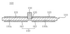
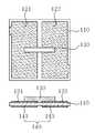
도 1a 및 도 1b에 도시한 바와 같이, 본 실시예에 따른 압전 액츄에이터(100)는 압전시트(110), 압전시트(110)에 형성된 제1 전극패턴(121) 및 제2 전극패턴(123), 전극부(140) 및 마찰부재(130)로 구성된다.
1A and 1B, the
상기 압전시트(110)는 전극패턴(제1 전극패턴(121), 제2 전극패턴(123))에 전압을 인가시 팽창 또는 수축하여 진동에 의한 구동력을 생성하기 위한 부재로서, 압전시트(110)의 일면에는 전극패턴(121, 123)이 형성된다. 본 발명에서는 제1 전극패턴(121)에 인가되는 전압의 상태에 따른 압전시트(110)의 변형 영역을 제1 진동부(110a), 제2 전극패턴(123)에 인가되는 전압의 상태에 따른 압전시트(110)의 변형 영역을 제2 진동부(110b)라 구분하여 설명한다. 즉, 압전시트(110)는 제1 진동부(110a)와 제2 진동부(110b)로 구분된다. 한편, 본 발명의 압전 액츄에이터(100)는 단층의 압전시트(110)로 구현될 수 있을 뿐만 아니라, 도 2에 도시한 바와 같이 2개 이상의 압전시트(110)가 적층된 형태로도 구현이 가능하다. 다층의 압전시트(압전적층체(160))로 압전 액츄에이터(100)를 구현하게 되면, 인가되는 전압에 대한 출력, 즉 진동력이 크기 때문에 낮은 전압으로 구동되어야 하는 전자제품(예를 들어, 휴대폰용 카메라 모듈)을 효율적으로 구동 가능하게 한다. 압전시트(110)는 압전 특성을 갖는 부재로서, 예를 들어 세라믹 재질로 형성되며, 반드시 이에 한정되는 것은 아니며, 당업계에 공지된 모든 재질을 채용할 수 있다.The
본 발명에 따른 압전 액츄에이터(100)의 구동방식은 다음과 같다. 도 3a에 도시한 바와 같이, 먼저 전극패턴(121,123)에 전압이 인가되는데, 제1 전극패턴(121)과 제2 전극패턴(123)에는 서로 180도의 위상차를 갖는 전압이 인가된다. 이때, 전극부(141, 143)는 접지된 상태이다. 구체적으로, 압전시트(110)의 일면 일측에 형성된 제1 전극패턴(121)과 압전시트(110)의 일면 타측에 형성된 제2 전극패턴(123)에 위상 차이를 갖는 전기신호가 서로 엇갈리게 인가되며, 각각의 전극패턴(121,123)에 인가되는 전압의 크기를 시간의 흐름에 따라 도시하면 도 11과 같다. 예를 들어, ch1에 사인파(초기의 위상이 양)가 인가될 때, ch2에 접지신호 또는 ch1에 인가된 사인파와 180도의 위상차를 갖는 사인파가 인가된다. 그 반대로 진동방향을 역으로 바꾸기 위해서는 ch1에 사인파(초기의 위상이 음)를 인가하고, ch2에 접지신호 또는 ch1에 인가된 사인파와 180도의 위상차를 갖는 사인파를 인가한다. 본 발명의 압전 액츄에이터(100)는 압전시트(110)의 수축과 팽창에 의해 발생하는 굴곡 진동을 이용하는 것인데, 전술한 바와 같이 180도의 위상차를 갖는 전기신호(도 11 참조)를 제1 전극패턴(121) 및 제2 전극패턴(123)에 각각 인가하면, 제1 진동부(110a; 도 1b)는 팽창하고 제2 진동부(110b; 도 1b)는 수축하면서(전기신호의 설정값에 따라 제1 진동부(110a)가 수축하고 제2 진동부(110b)가 팽창하는 경우도 마찬가지이다.), 압전시트(110)는 도 9에 도시한 바와 같이 평면방향에서 병진 운동(도 9의 경우 X축 방향의 병진 운동)을 하게 된다. 마찰부재(130)는 압전시트(110)의 일면에 형성되어, 압전시트(110)의 선형 병진 운동에 의한 진동력을 피마찰부재(미도시; 예를 들어 로터 또는 슬라이드)에 전달한다.The driving method of the
한편, 도 3b에 도시한 방식으로 전압을 인가하는 것도 가능하다. 먼저 제1 전극패턴(121)과 제2 전극부(143)는 전기적으로 연결되어 있고, 제2 전극패턴(123)과 제1 전극부(141) 역시 전기적으로 연결되어 있다. 따라서, 제1 전극패턴(121)과 제2 전극부(143)에 동일한 위상을 갖는 전압이 인가되고, 제2 전극패턴(123)과 제1 전극부(141)에 동일한 위상을 갖는 전압이 인가된다. 이후, 제1 전극패턴(121) 및 제2 전극부(143), 제2 전극패턴(123) 및 제1 전극부(141)에 전압을 각각 인가하며, 이때 각각의 전압은 180도의 위상차를 갖는다. 180도의 위상차를 갖는 전압이 인가되는 형태는 전술한 바와 같다. 전압에 의해 제1 진동부(110a; 도 1b) 및 제2 진동부(110b; 도 1b)가 수축/팽창 운동함으로써 압전시트(110)를 진동시키고, 압전시트(110)의 진동에 의해 마찰부재(130)가 평면상에서 선형 병진 운동한다. 도 3c는 도 2에 도시한 압전액츄에이터(100)에 전압이 인가되는 방식을 설명하기 위한 도면으로서, 그 전압 인가 방식은 전술한 바와 같다.
On the other hand, it is also possible to apply a voltage in the manner shown in Fig. 3B. First, the
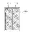
상기 전극패턴(제1 전극패턴(121), 제2 전극패턴(123))은 압전시트(110)의 일면에 형성되고, 상기 전극부(140)는 압전시트(110)의 타면에 형성된다. 여기서, 전극부(140)는 압전시트(110)의 타면의 전면에 형성될 수 있으며, 또한, 도 1b에서 도시한 바와 같이, 제1 전극부(141) 및 제2 전극부(143)로 구분되어 제1 전극패턴(121) 및 제2 전극패턴(123)과 대응되도록 형성될 수도 있다. 여기서, 제1 전극패턴(121) 및 제2 전극패턴(123)은 압전시트(110)의 중앙점(압전시트(110)의 두 대각선의 교차점)에 대하여 대칭되도록 형성되는 것이 바람직하다. 제1 전극패턴(121)은 입력되는 전기신호의 형태에 따라 제1 진동부(110a)에 굴곡(수축 또는 팽창) 진동을 발생시키고, 제2 전극패턴(123)은 입력되는 전기신호의 형태에 따라 제2 진동부(110b)에 굴곡(팽창 또는 수축) 진동을 발생시킨다.The electrode patterns (the
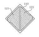
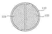
한편, 도 4에 도시한 바와 같이, 제1 전극패턴(121) 및 제2 전극패턴(123)은 사각형(도 4a, 도 4b), 삼각형(도 4c) 또는 반원형(도 4d)의 형상을 가지며, 압전시트(110)의 타면에 형성된 전극부(140; 도 1b 참조)도 제1 전극패턴(121) 및 제2 전극패턴(123)의 배열 형상과 대응하도록 형성될 수 있다.
Meanwhile, as shown in FIG. 4, the
상기 마찰부재(130)는 압전시트(110)(도 2의 경우 압전적층체(160))로부터 발생하는 진동을 외부로 전달하기 위한 부재이다. 본 발명에 따른 압전 액츄에이터(100)가 채용되는 전자부품에 따라 차이가 있을 것이나, 일반적으로 마찰부재(130)에 로터 또는 슬라이드가 접촉할 수 있다. 마찰부재(130)는 압전시트(110) 일면에 본딩제로 부착되거나, 압전시트(110)에 형성된 홈부(135; 도 1b)에 본딩제로 부착될 수 있다. 즉, 압전시트(110)에는 오목하게 함몰된 홈부(135)가 형성되어 있고, 마찰부재(130)의 일부가 홈부(135)에 삽입되어 압전시트(110)에 부착되어 있다. 여기서 마찰부재(130)는 평면상의 선형 병진 운동을 수행하여 피마찰부재에 진동력을 전달한다.The
한편, 도 1 또는 도 2에 도시한 바와 같이, 마찰부재(130)는 제1 전극패턴(121) 및 제2 전극패턴(123) 사이에 형성되어 있고, 마찰부재(130)의 횡단면은 원형 또는 사각형의 형상을 갖는다. 마찰부재(130)의 구체적인 형상은 도 5에 도시한 바와 같다. 즉, 마찰부재(130)는 반구 형상(도 5a) 또는 육면체 형상(도 5b 또는 도 5c)으로 제1 전극패턴(121) 및 제2 전극패턴(123) 사이에 노출된 압전시트(110)로부터 돌출되도록 형성된다. 또한, 제1 전극패턴(121) 및 제2 전극패턴(123)을 가로지르는 육면체의 형상(도 5d)을 가질 수 있으며, 이외에도 피마찰부재에 마찰력을 전달할 수 있는 형상이라면 도 5에 도시한 형상에 구애받지 않고 변형이 가능하다. 한편, 마찰부재(130)는 내마모성이 우수하고 마찰계수가 큰 재질로 형성되는 것이 바람직하며, Al2O3 또는 ZrO2등의 세라믹 재질, 텅스텐 카바이드(WC)계 초경합금, 공구강, 또는 고속도강의 소재를 사용하거나, 일반 금속소재에 TiN, CrN, WC를 코팅시켜 경도를 높인 소재로 형성될 수 있다.
On the other hand, as shown in Figure 1 or 2, the
제22nd실시예에Example 따른 압전 According to the piezoelectric액츄에이터Actuator
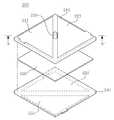
도 6 및 도 7은 본 발명의 바람직한 제2 실시예에 따른 압전 액츄에이터의 구조를 도시한 사시도 및 단면도이다.6 and 7 are a perspective view and a cross-sectional view showing the structure of a piezoelectric actuator according to a second preferred embodiment of the present invention.
본 발명의 바람직한 제2 실시예에 따른 압전 액츄에이터(200)는, 제1 압전시트(210), 제1 압전시트(210)의 일면에 형성된 제1 전극패턴(221) 및 제2 전극패턴(223), 제1 압전시트(210)의 타면에 형성된 접지전극(230), 접지전극(230)이 형성된 제1 압전시트(210)의 하부에 형성된 제2 압전시트(240), 제2 압전시트(240)의 하측면에 형성된 제3 전극패턴(251) 및 제4 전극패턴(253), 제1 압전시트(210)의 일면에 형성된 마찰부재(270)를 포함하여 구성된다.
The
여기서, 제3 전극패턴(251) 및 제4 전극패턴(253)은, 제1 전극패턴(221) 및 제2 전극패턴(223)을 기준으로 90도 교차되도록, 제2 압전시트(240)의 하측면에 형성된다(도 6). 즉, 제1 압전시트(210)를 제2 압전시트(240)에 적층하되, 제1 전극패턴(221) 및 제2 전극패턴(223)이 제2 압전시트(240)에 형성된 제3 전극패턴(251) 및 제4 전극패턴(253)과 제1 압전시트의 중앙점을 축으로 평면상에서 90도 교차하도록 적층한다. 이는 평면상에서 제1 방향 또는 제2 방향의 두 방향으로 병진 운동할 수 있는 압전 액츄에이터(200)를 구현하기 위한 것이다.Here, the
본 발명의 바람직한 제2 실시예에 따른 압전 액츄에이터(200)를 구성하는 압전시트(제1 압전시트(210), 제2 압전시트(240)), 전극패턴(221,223,251,253) 및 접지전극(230), 마찰부재(270)에 관련된 상세한 설명은 전술한 제1 실시예에 따른 압전 액츄에이터(100; 도 1)와 동일하므로 여기서 반복 설명은 생략하기로 한다.Piezoelectric sheet (first
한편, 본 실시예에 따른 압전 액츄에이터(200)의 구동방식은 다음과 같다. 다만, 제1 압전시트(210) 또는 제2 압전시트(240) 자체의 병진 운동 방식은 전술한 제1 실시예에 따른 압전 액츄에이터(100; 도 1)와 동일하다. 다시 말해, 제1 전극패턴(221) 및 제2 전극패턴(223)에 180도의 위상차를 갖는 전기신호를 인가해주어 제1 진동부(210a) 및 제2 진동부(210b)의 팽창 수축운동을 이용하여 선형 병진 운동을 발생시킨다.On the other hand, the driving method of the
다만, 본 실시예에서는, 제3 전극패턴(251) 및 제4 전극패턴(253)에는 전기신호를 인가하지 않은 상태에서 제1 전극패턴(221) 및 제2 전극패턴(223)에만 서로 180도 위상차를 갖는 전압을 인가한다(도 8a 참조). 이 경우, 제2 압전시트(240)는 별도로 진동을 발생시키지 않은 채로 제1 압전시트(210)의 하면에 부착되어 있고, 제1 압전시트(210)만이 평면상에서 제1 방향으로 병진 운동을 한다. 이때, 병진 운동의 방향은 제1 방향(즉, X축방향; 도 10a 참조)이 될 것이다. 한편, 이와 반대로, 제1 전극패턴(221) 및 제2 전극패턴(223)에는 전기신호를 인가하지 않은 상태에서 제3 전극패턴(251) 및 제4 전극패턴(253)에만 서로 180도 위상차를 갖는 전압을 인가한다(도 8b 참조). 이 경우, 제1 압전시트(210)는 별도로 진동을 발생시키지 않은 채로 제2 압전시트(240)의 상면에 부착되어 있고, 제2 압전시트(240)만이 평면상에서 제2 방향으로 병진 운동을 한다. 이때, 병진 운동의 방향은 제2 방향(즉, Y축방향; 도 10b 참조)이 될 것이다. 본 발명의 바람직한 제2 실시예에 따른 압전 액츄에이터(200)는, 전기신호를 달리 인가함으로써 하나의 압전 액츄에이터(200)에 제1 방향 또는 제2 방향의 병진 운동을 독립적으로 유도할 수 있다는 점에 그 기술적 특징이 존재한다. 이러한 양 방향의 병진 운동은 휴대폰용 카메라 모듈로 사용되어 손떨림 보정장치(OIS; Optical Image Stabilizer)에 적용이 가능하다. 특히, 카메라 모듈의 소형화, 시스템의 간소화, 작동의 용이성을 개선시킬 수 있는 이점이 있다.
However, in the present exemplary embodiment, only the
이상 본 발명의 바람직한 실시예에 대하여 상세히 설명하였으나, 이는 본 발명을 구체적으로 설명하기 위한 것으로, 본 발명에 따른 압전 액츄에이터는 이에 한정되지 않으며, 본 발명의 기술적 사상 내에서 당해 분야의 통상의 지식을 가진 자에 의해 그 변형이나 개량이 가능함은 명백하다고 할 것이다.Although a preferred embodiment of the present invention has been described in detail, this is for the purpose of describing the present invention in detail, the piezoelectric actuator according to the present invention is not limited to this, within the technical spirit of the present invention, It is obvious that modifications and improvements are possible by those who have them.
본 발명의 단순한 변형 내지 변경은 모두 본 발명의 영역에 속하는 것으로, 본 발명의 구체적인 보호 범위는 첨부된 특허청구범위에 의하여 명확해 질 것이다.
All simple modifications and variations of the present invention fall within the scope of the present invention, and the specific scope of protection of the present invention will be apparent from the appended claims.
100 : 압전 액츄에이터110 : 압전시트
110a, 210a : 제1 진동부110b, 210b : 제2 진동부
121 : 제1 전극패턴 123 : 제2 전극패턴
130 : 마찰부재135 : 홈부
140 : 전극부141 : 제1 전극부
143 : 제2 전극부160 : 압전적층체
200 : 압전 액츄에이터210 : 제1 압전시트
221 : 제1 전극패턴223 : 제2 전극패턴
230 : 접지전극 240 : 제2 압전시트
251 : 제3 전극패턴253 : 제4 전극패턴
270 : 마찰부재275 : 홈부100: piezoelectric actuator 110: piezoelectric sheet
110a, 210a: first vibrating
121: first electrode pattern 123: second electrode pattern
130: friction member 135: groove
140: electrode portion 141: first electrode portion
143: second electrode portion 160: piezoelectric laminate
200: piezoelectric actuator 210: first piezoelectric sheet
221: first electrode pattern 223: second electrode pattern
230: ground electrode 240: second piezoelectric sheet
251: third electrode pattern 253: fourth electrode pattern
270: friction member 275: groove
Claims (20)
Translated fromKorean상기 압전시트의 일면 일측에 형성된 제1 전극패턴;
상기 제1 전극패턴과 전기적으로 분리되도록 상기 압전시트의 일면 타측에 형성된 제2 전극패턴;
상기 압전시트의 타면에 형성된 전극부;
상기 압전시트의 일면에 형성되어 상기 압전시트로부터 돌출된 마찰부재;
를 포함하는 것을 특징으로 하는 압전 액츄에이터.
Piezoelectric sheet;
A first electrode pattern formed on one side of the piezoelectric sheet;
A second electrode pattern formed on the other side of one surface of the piezoelectric sheet to be electrically separated from the first electrode pattern;
An electrode part formed on the other surface of the piezoelectric sheet;
A friction member formed on one surface of the piezoelectric sheet and protruding from the piezoelectric sheet;
Piezoelectric actuator comprising a.
상기 전극부는 상기 제1 전극패턴과 대응하도록 상기 압전시트의 타면에 형성된 제1 전극부 및 상기 제2 전극패턴과 대응하고 상기 제1 전극부와 전기적으로 분리되도록 상기 압전시트의 타면에 형성된 제2 전극부로 구성되는 것을 특징으로 하는 압전 액츄에이터.
The method according to claim 1,
The electrode part is formed on the other surface of the piezoelectric sheet to correspond to the first electrode pattern and the second electrode formed on the other surface of the piezoelectric sheet to correspond to the second electrode pattern and to be electrically separated from the first electrode part. A piezoelectric actuator comprising an electrode portion.
상기 압전시트가 다수 적층되어 압전적층체를 형성하는 것을 특징으로 하는 압전 액츄에이터.
The method according to claim 1,
A plurality of piezoelectric sheets are laminated to form a piezoelectric laminate.
상기 제1 전극패턴 및 상기 제2 전극패턴에 서로 180도의 위상차를 갖는 전압이 인가되어 상기 압전시트가 진동하고,
상기 압전시트의 진동에 의해 상기 마찰부재가 평면상에서 선형 병진 운동하는 것을 특징으로 하는 압전 액츄에이터.
The method according to claim 1,
A voltage having a phase difference of 180 degrees is applied to the first electrode pattern and the second electrode pattern to vibrate the piezoelectric sheet,
Piezoelectric actuator, characterized in that the friction member linearly translates in the plane by the vibration of the piezoelectric sheet.
상기 제1 전극패턴과 상기 제2 전극부에 동일한 위상을 갖는 전압이 인가되고, 상기 제2 전극패턴과 상기 제1 전극부에 동일한 위상을 갖는 전압이 인가되며,
상기 제1 전극패턴 및 상기 제2 전극부에 인가되는 전압과 상기 제2 전극패턴 및 상기 제1 전극부에 인가되는 전압은 180도의 위상차를 갖고,
전압의 인가에 의해 상기 압전시트가 진동하며,
상기 압전시트의 진동에 의해 상기 마찰부재가 평면상에서 선형 병진 운동하는 것을 특징으로 하는 압전 액츄에이터.
The method according to claim 2,
A voltage having the same phase is applied to the first electrode pattern and the second electrode part, a voltage having the same phase is applied to the second electrode pattern and the first electrode part,
The voltage applied to the first electrode pattern and the second electrode portion and the voltage applied to the second electrode pattern and the first electrode portion have a phase difference of 180 degrees.
The piezoelectric sheet vibrates by the application of a voltage,
Piezoelectric actuator, characterized in that the friction member linearly translates in the plane by the vibration of the piezoelectric sheet.
상기 압전시트에 오목하게 함몰된 홈부가 형성되어 있고, 상기 마찰부재의 일부가 상기 홈부에 삽입된 것을 특징으로 하는 압전 액츄에이터.
The method according to claim 1,
The piezoelectric actuator is formed with a recessed recess in the piezoelectric sheet, and a part of the friction member is inserted into the groove.
상기 마찰부재는 상기 제1 전극패턴 및 상기 제2 전극패턴 사이에 형성되어 있고, 상기 마찰부재의 횡단면은 원형 또는 사각형인 것을 특징으로 하는 압전 액츄에이터.
The method according to claim 1,
The friction member is formed between the first electrode pattern and the second electrode pattern, the cross section of the friction member is a piezoelectric actuator, characterized in that the circular or rectangular.
상기 마찰부재는 Al2O3 또는 ZrO2의 세라믹 재질, 텅스텐 카바이드(WC)계 초경합금, 공구강, 또는 고속도강의 소재로 형성된 것을 특징으로 하는 압전 액츄에이터.
The method according to claim 1,
The friction member is a piezoelectric actuator, characterized in that formed of a ceramic material of Al2 O3 or ZrO2 , tungsten carbide (WC) cemented carbide, tool steel, or high speed steel.
상기 제1 전극패턴 및 상기 제2 전극패턴은 상기 압전시트의 중앙점에 대하여 대칭인 것을 특징으로 하는 압전 액츄에이터.
The method according to claim 1,
The first electrode pattern and the second electrode pattern is a piezoelectric actuator, characterized in that symmetrical with respect to the center point of the piezoelectric sheet.
상기 제1 전극패턴 및 상기 제2 전극패턴은 사각형, 삼각형 또는 반원형의 형상을 갖는 것을 특징으로 하는 압전 액츄에이터.
The method according to claim 1,
The first electrode pattern and the second electrode pattern is a piezoelectric actuator, characterized in that the shape of a square, triangle or semi-circular.
상기 제1 압전시트의 일면 일측에 형성된 제1 전극패턴 및 상기 제1 전극패턴과 전기적으로 분리되도록 상기 제1 압전시트의 일면 타측에 형성된 제2 전극패턴;
상기 제1 압전시트의 타면에 형성된 접지전극;
상기 접지전극이 형성된 상기 제1 압전시트의 하부에 형성된 제2 압전시트;
상기 제2 압전시트의 하측면 일측에 형성된 제3 전극패턴 및 상기 제3 전극패턴과 전기적으로 분리되도록 상기 제2 압전시트의 하측면 타측에 형성된 제4 전극패턴;
상기 제1 압전시트의 일면에 형성된 마찰부재;
를 포함하는 것을 특징으로 하는 압전 액츄에이터.
First piezoelectric sheet;
A first electrode pattern formed on one side of the first piezoelectric sheet and a second electrode pattern formed on the other side of the first piezoelectric sheet so as to be electrically separated from the first electrode pattern;
A ground electrode formed on the other surface of the first piezoelectric sheet;
A second piezoelectric sheet formed below the first piezoelectric sheet on which the ground electrode is formed;
A third electrode pattern formed on one side of the lower side of the second piezoelectric sheet and a fourth electrode pattern formed on the other side of the lower side of the second piezoelectric sheet so as to be electrically separated from the third electrode pattern;
A friction member formed on one surface of the first piezoelectric sheet;
Piezoelectric actuator comprising a.
상기 제3 전극패턴 및 상기 제4 전극패턴은, 상기 제1 전극패턴 및 상기 제2 전극패턴을 기준으로 90도 교차되도록, 상기 제2 압전시트에 형성된 것을 특징으로 하는 압전 액츄에이터.
The method of claim 11,
The third electrode pattern and the fourth electrode pattern, the piezoelectric actuator, characterized in that formed on the second piezoelectric sheet so as to cross 90 degrees with respect to the first electrode pattern and the second electrode pattern.
상기 제1 전극패턴 및 상기 제2 전극패턴에만 서로 180도 위상차를 갖는 전압을 인가함으로써 상기 제1 압전시트 및 상기 제2 압전시트가 평면상의 제1 방향으로 병진 운동을 하고, 상기 제3 전극패턴 및 상기 제4 전극패턴에만 서로 180도 위상차를 갖는 전압을 인가함으로써 상기 제1 압전시트 및 상기 제2 압전시트가 평면상의 제2 방향으로 병진 운동을 하여, 상기 제1 압전시트 및 상기 제2 압전시트가 일체로서 제1 방향 또는 제2 방향으로 진동하는 것을 특징으로 하는 압전 액츄에이터.
The method of claim 12,
By applying a voltage having a phase difference of 180 degrees to only the first electrode pattern and the second electrode pattern, the first piezoelectric sheet and the second piezoelectric sheet translate in a first direction on a plane, and the third electrode pattern And applying the voltage having a phase difference of 180 degrees to only the fourth electrode pattern so that the first piezoelectric sheet and the second piezoelectric sheet are translated in a second direction on a plane, thereby providing the first piezoelectric sheet and the second piezoelectric. A piezoelectric actuator, wherein the sheet vibrates in a first direction or a second direction as a unit.
상기 제1 압전시트에 오목하게 함몰된 홈부가 형성되어 있고, 상기 마찰부재의 일부가 상기 홈부에 삽입된 것을 특징으로 하는 압전 액츄에이터.
The method of claim 11,
The first piezoelectric sheet is recessed recessed groove portion is formed, the piezoelectric actuator, characterized in that a portion of the friction member is inserted into the groove portion.
상기 마찰부재는 상기 제1 전극패턴 및 상기 제2 전극패턴 사이에 형성되어 있고, 상기 마찰부재의 횡단면은 원형 또는 사각형인 것을 특징으로 하는 압전 액츄에이터.
The method of claim 11,
The friction member is formed between the first electrode pattern and the second electrode pattern, the cross section of the friction member is a piezoelectric actuator, characterized in that the circular or rectangular.
상기 마찰부재는 Al2O3 또는 ZrO2의 세라믹 재질, 텅스텐 카바이드(WC)계 초경합금, 공구강, 또는 고속도강의 소재로 형성된 것을 특징으로 하는 압전 액츄에이터.
The method of claim 11,
The friction member is a piezoelectric actuator, characterized in that formed of a ceramic material of Al2 O3 or ZrO2 , tungsten carbide (WC) cemented carbide, tool steel, or high speed steel.
상기 제1 전극패턴 및 상기 제2 전극패턴은 상기 제1 압전시트의 중앙점에 대하여 대칭인 것을 특징으로 하는 압전 액츄에이터.
The method of claim 11,
The first electrode pattern and the second electrode pattern is a piezoelectric actuator, characterized in that symmetrical with respect to the center point of the first piezoelectric sheet.
상기 제1 전극패턴 및 상기 제2 전극패턴은 사각형, 삼각형 또는 반원형의 형상을 갖는 것을 특징으로 하는 압전 액츄에이터.
The method of claim 11,
The first electrode pattern and the second electrode pattern is a piezoelectric actuator, characterized in that the shape of a square, triangle or semi-circular.
상기 제3 전극패턴 및 상기 제4 전극패턴은 상기 제2 압전시트의 중앙점에 대하여 대칭인 것을 특징으로 하는 압전 액츄에이터.
The method of claim 11,
And the third electrode pattern and the fourth electrode pattern are symmetrical with respect to a center point of the second piezoelectric sheet.
상기 제3 전극패턴 및 상기 제4 전극패턴은 사각형, 삼각형 또는 반원형의 형상을 갖는 것을 특징으로 하는 압전 액츄에이터.
The method of claim 11,
The third electrode pattern and the fourth electrode pattern is a piezoelectric actuator, characterized in that the shape of a square, triangle or semi-circular.
Priority Applications (3)
| Application Number | Priority Date | Filing Date | Title |
|---|---|---|---|
| US13/082,961US20120169181A1 (en) | 2010-12-30 | 2011-04-08 | Piezoelectric Actuator |
| EP11163267.5AEP2472621A3 (en) | 2010-12-30 | 2011-04-20 | Piezoelectric actuator |
| CN201110104240.2ACN102544350B (en) | 2010-12-30 | 2011-04-22 | Piezo-activator |
Applications Claiming Priority (2)
| Application Number | Priority Date | Filing Date | Title |
|---|---|---|---|
| KR1020100139610 | 2010-12-30 | ||
| KR20100139610 | 2010-12-30 |
Publications (1)
| Publication Number | Publication Date |
|---|---|
| KR20120078529Atrue KR20120078529A (en) | 2012-07-10 |
Family
ID=46711861
Family Applications (1)
| Application Number | Title | Priority Date | Filing Date |
|---|---|---|---|
| KR1020110004032AWithdrawnKR20120078529A (en) | 2010-12-30 | 2011-01-14 | Piezoelectric actuator |
Country Status (1)
| Country | Link |
|---|---|
| KR (1) | KR20120078529A (en) |
Cited By (16)
| Publication number | Priority date | Publication date | Assignee | Title |
|---|---|---|---|---|
| WO2014081871A1 (en)* | 2012-11-21 | 2014-05-30 | Novasentis, Inc. | Emp actuators for deformable surface and keyboard application |
| US9053617B2 (en) | 2012-11-21 | 2015-06-09 | Novasentis, Inc. | Systems including electromechanical polymer sensors and actuators |
| US9164586B2 (en) | 2012-11-21 | 2015-10-20 | Novasentis, Inc. | Haptic system with localized response |
| US9183710B2 (en) | 2012-08-03 | 2015-11-10 | Novasentis, Inc. | Localized multimodal electromechanical polymer transducers |
| US9269885B2 (en) | 2012-11-21 | 2016-02-23 | Novasentis, Inc. | Method and localized haptic response system provided on an interior-facing surface of a housing of an electronic device |
| US9357312B2 (en) | 2012-11-21 | 2016-05-31 | Novasentis, Inc. | System of audio speakers implemented using EMP actuators |
| US9370640B2 (en) | 2007-09-12 | 2016-06-21 | Novasentis, Inc. | Steerable medical guide wire device |
| US9507468B2 (en) | 2013-08-30 | 2016-11-29 | Novasentis, Inc. | Electromechanical polymer-based sensor |
| US9576446B2 (en) | 2014-08-07 | 2017-02-21 | Novasentis, Inc. | Ultra-thin haptic switch with lighting |
| US9652946B2 (en) | 2014-05-02 | 2017-05-16 | Novasentis, Inc. | Hands-free, wearable vibration devices and method |
| US9666391B2 (en) | 2013-10-22 | 2017-05-30 | Novasentis, Inc. | Retractable snap domes |
| US9705068B2 (en) | 2012-06-19 | 2017-07-11 | Novasentis, Inc. | Ultra-thin inertial actuator |
| US9833596B2 (en) | 2013-08-30 | 2017-12-05 | Novasentis, Inc. | Catheter having a steerable tip |
| US9972768B2 (en) | 2014-08-15 | 2018-05-15 | Novasentis, Inc. | Actuator structure and method |
| US10088936B2 (en) | 2013-01-07 | 2018-10-02 | Novasentis, Inc. | Thin profile user interface device and method providing localized haptic response |
| US10125758B2 (en) | 2013-08-30 | 2018-11-13 | Novasentis, Inc. | Electromechanical polymer pumps |
- 2011
- 2011-01-14KRKR1020110004032Apatent/KR20120078529A/ennot_activeWithdrawn
Cited By (18)
| Publication number | Priority date | Publication date | Assignee | Title |
|---|---|---|---|---|
| US9370640B2 (en) | 2007-09-12 | 2016-06-21 | Novasentis, Inc. | Steerable medical guide wire device |
| US9705068B2 (en) | 2012-06-19 | 2017-07-11 | Novasentis, Inc. | Ultra-thin inertial actuator |
| US9183710B2 (en) | 2012-08-03 | 2015-11-10 | Novasentis, Inc. | Localized multimodal electromechanical polymer transducers |
| US9053617B2 (en) | 2012-11-21 | 2015-06-09 | Novasentis, Inc. | Systems including electromechanical polymer sensors and actuators |
| US9170650B2 (en) | 2012-11-21 | 2015-10-27 | Novasentis, Inc. | EMP actuators for deformable surface and keyboard application |
| US9269885B2 (en) | 2012-11-21 | 2016-02-23 | Novasentis, Inc. | Method and localized haptic response system provided on an interior-facing surface of a housing of an electronic device |
| US9357312B2 (en) | 2012-11-21 | 2016-05-31 | Novasentis, Inc. | System of audio speakers implemented using EMP actuators |
| US9164586B2 (en) | 2012-11-21 | 2015-10-20 | Novasentis, Inc. | Haptic system with localized response |
| WO2014081871A1 (en)* | 2012-11-21 | 2014-05-30 | Novasentis, Inc. | Emp actuators for deformable surface and keyboard application |
| US10088936B2 (en) | 2013-01-07 | 2018-10-02 | Novasentis, Inc. | Thin profile user interface device and method providing localized haptic response |
| US9833596B2 (en) | 2013-08-30 | 2017-12-05 | Novasentis, Inc. | Catheter having a steerable tip |
| US9507468B2 (en) | 2013-08-30 | 2016-11-29 | Novasentis, Inc. | Electromechanical polymer-based sensor |
| US10125758B2 (en) | 2013-08-30 | 2018-11-13 | Novasentis, Inc. | Electromechanical polymer pumps |
| US10709871B2 (en) | 2013-08-30 | 2020-07-14 | Strategic Polymer Sciences, Inc. | Catheter having a steerable tip |
| US9666391B2 (en) | 2013-10-22 | 2017-05-30 | Novasentis, Inc. | Retractable snap domes |
| US9652946B2 (en) | 2014-05-02 | 2017-05-16 | Novasentis, Inc. | Hands-free, wearable vibration devices and method |
| US9576446B2 (en) | 2014-08-07 | 2017-02-21 | Novasentis, Inc. | Ultra-thin haptic switch with lighting |
| US9972768B2 (en) | 2014-08-15 | 2018-05-15 | Novasentis, Inc. | Actuator structure and method |
Similar Documents
| Publication | Publication Date | Title |
|---|---|---|
| KR20120078529A (en) | Piezoelectric actuator | |
| CN100502074C (en) | piezoelectric ultrasonic motor | |
| CN103259449B (en) | Piezoelectric actuator and piezo-electric motor | |
| CN102544350B (en) | Piezo-activator | |
| KR20170054432A (en) | Mems having micromechanical piezoelectric actuators for realizing high forces and deflections | |
| US7667373B2 (en) | Drive unit | |
| KR20130030704A (en) | Transducer and transducer module | |
| JP2013092513A (en) | Method of generating 3d haptic feedback and handheld electronic device | |
| CN113453808A (en) | Piezoelectric actuator with amplified deformation | |
| JP2014018027A (en) | Vibration type actuator, imaging apparatus, and stage | |
| KR101045996B1 (en) | Piezoelectric linear motor | |
| CN102569637B (en) | Piezoelectric Actuators and Piezoelectric Motors | |
| CN105915105A (en) | Inertia piezoelectric driver | |
| CN102946579B (en) | Vibration material, virtual haptic maker, touch module and vibrating diaphragm | |
| KR20110001033A (en) | Ultrasonic Motor and Manufacturing Method Thereof | |
| EP2555175A1 (en) | Transducer module | |
| CN119836792A (en) | Microfluidic interaction element for generating and/or detecting a volumetric flow of a fluid and acoustic device having such a microfluidic interaction element | |
| JP2009296794A (en) | Inertia-driven actuator | |
| CN106059377A (en) | Stepping piezoelectric actuator | |
| KR101544834B1 (en) | piezo-electric vibrator | |
| WO2020152905A1 (en) | Stacked piezoelectric element and piezoelectric actuator | |
| KR20170040616A (en) | Piezoelectric actuator for electrical device | |
| JP5540249B1 (en) | Vibration device and electronic device | |
| EP2586538A2 (en) | Transducer module | |
| JP2012029478A (en) | Vibrator and ultrasonic motor |
Legal Events
| Date | Code | Title | Description |
|---|---|---|---|
| PA0109 | Patent application | Patent event code:PA01091R01D Comment text:Patent Application Patent event date:20110114 | |
| PG1501 | Laying open of application | ||
| PC1203 | Withdrawal of no request for examination | ||
| WITN | Application deemed withdrawn, e.g. because no request for examination was filed or no examination fee was paid |