KR20120072322A - Bone anchoring device - Google Patents
Bone anchoring deviceDownload PDFInfo
- Publication number
- KR20120072322A KR20120072322AKR1020110138379AKR20110138379AKR20120072322AKR 20120072322 AKR20120072322 AKR 20120072322AKR 1020110138379 AKR1020110138379 AKR 1020110138379AKR 20110138379 AKR20110138379 AKR 20110138379AKR 20120072322 AKR20120072322 AKR 20120072322A
- Authority
- KR
- South Korea
- Prior art keywords
- head
- bone fixation
- fixation device
- pressing element
- pressing
- Prior art date
- Legal status (The legal status is an assumption and is not a legal conclusion. Google has not performed a legal analysis and makes no representation as to the accuracy of the status listed.)
- Withdrawn
Links
- 210000000988bone and boneAnatomy0.000titleclaimsabstractdescription47
- 238000004873anchoringMethods0.000title1
- 238000003825pressingMethods0.000claimsabstractdescription43
- 230000036316preloadEffects0.000claimsabstractdescription7
- 239000000463materialSubstances0.000claimsabstractdescription6
- 239000013536elastomeric materialSubstances0.000claims1
- 238000002788crimpingMethods0.000description6
- 239000004696Poly ether ether ketoneSubstances0.000description2
- 239000004699Ultra-high molecular weight polyethyleneSubstances0.000description2
- JUPQTSLXMOCDHR-UHFFFAOYSA-Nbenzene-1,4-diol;bis(4-fluorophenyl)methanoneChemical compoundOC1=CC=C(O)C=C1.C1=CC(F)=CC=C1C(=O)C1=CC=C(F)C=C1JUPQTSLXMOCDHR-UHFFFAOYSA-N0.000description2
- 230000006835compressionEffects0.000description2
- 238000007906compressionMethods0.000description2
- 229920001971elastomerPolymers0.000description2
- 239000000806elastomerSubstances0.000description2
- 238000003780insertionMethods0.000description2
- 230000037431insertionEffects0.000description2
- 239000004033plasticSubstances0.000description2
- 229920003023plasticPolymers0.000description2
- 229920002530polyetherether ketonePolymers0.000description2
- 230000000087stabilizing effectEffects0.000description2
- 229920000785ultra high molecular weight polyethylenePolymers0.000description2
- RTAQQCXQSZGOHL-UHFFFAOYSA-NTitaniumChemical compound[Ti]RTAQQCXQSZGOHL-UHFFFAOYSA-N0.000description1
- 230000008878couplingEffects0.000description1
- 238000010168coupling processMethods0.000description1
- 238000005859coupling reactionMethods0.000description1
- 230000001419dependent effectEffects0.000description1
- 238000011161developmentMethods0.000description1
- 230000018109developmental processEffects0.000description1
- 230000003993interactionEffects0.000description1
- 229910052751metalInorganic materials0.000description1
- 239000002184metalSubstances0.000description1
- 229910001092metal group alloyInorganic materials0.000description1
- 238000000034methodMethods0.000description1
- HLXZNVUGXRDIFK-UHFFFAOYSA-Nnickel titaniumChemical compound[Ti].[Ti].[Ti].[Ti].[Ti].[Ti].[Ti].[Ti].[Ti].[Ti].[Ti].[Ni].[Ni].[Ni].[Ni].[Ni].[Ni].[Ni].[Ni].[Ni].[Ni].[Ni].[Ni].[Ni].[Ni]HLXZNVUGXRDIFK-UHFFFAOYSA-N0.000description1
- 229910001000nickel titaniumInorganic materials0.000description1
- 229920001296polysiloxanePolymers0.000description1
- 239000007787solidSubstances0.000description1
- 239000010936titaniumSubstances0.000description1
- 229910052719titaniumInorganic materials0.000description1
Images


Classifications
- A—HUMAN NECESSITIES
- A61—MEDICAL OR VETERINARY SCIENCE; HYGIENE
- A61B—DIAGNOSIS; SURGERY; IDENTIFICATION
- A61B17/00—Surgical instruments, devices or methods
- A61B17/56—Surgical instruments or methods for treatment of bones or joints; Devices specially adapted therefor
- A61B17/58—Surgical instruments or methods for treatment of bones or joints; Devices specially adapted therefor for osteosynthesis, e.g. bone plates, screws or setting implements
- A61B17/68—Internal fixation devices, including fasteners and spinal fixators, even if a part thereof projects from the skin
- A61B17/84—Fasteners therefor or fasteners being internal fixation devices
- A61B17/86—Pins or screws or threaded wires; nuts therefor
- A—HUMAN NECESSITIES
- A61—MEDICAL OR VETERINARY SCIENCE; HYGIENE
- A61B—DIAGNOSIS; SURGERY; IDENTIFICATION
- A61B17/00—Surgical instruments, devices or methods
- A61B17/56—Surgical instruments or methods for treatment of bones or joints; Devices specially adapted therefor
- A61B17/58—Surgical instruments or methods for treatment of bones or joints; Devices specially adapted therefor for osteosynthesis, e.g. bone plates, screws or setting implements
- A61B17/68—Internal fixation devices, including fasteners and spinal fixators, even if a part thereof projects from the skin
- A61B17/70—Spinal positioners or stabilisers, e.g. stabilisers comprising fluid filler in an implant
- A61B17/7001—Screws or hooks combined with longitudinal elements which do not contact vertebrae
- A61B17/7035—Screws or hooks, wherein a rod-clamping part and a bone-anchoring part can pivot relative to each other
- A61B17/7037—Screws or hooks, wherein a rod-clamping part and a bone-anchoring part can pivot relative to each other wherein pivoting is blocked when the rod is clamped
- A—HUMAN NECESSITIES
- A61—MEDICAL OR VETERINARY SCIENCE; HYGIENE
- A61B—DIAGNOSIS; SURGERY; IDENTIFICATION
- A61B17/00—Surgical instruments, devices or methods
- A61B17/56—Surgical instruments or methods for treatment of bones or joints; Devices specially adapted therefor
- A61B17/58—Surgical instruments or methods for treatment of bones or joints; Devices specially adapted therefor for osteosynthesis, e.g. bone plates, screws or setting implements
- A61B17/68—Internal fixation devices, including fasteners and spinal fixators, even if a part thereof projects from the skin
- A61B17/70—Spinal positioners or stabilisers, e.g. stabilisers comprising fluid filler in an implant
- Y—GENERAL TAGGING OF NEW TECHNOLOGICAL DEVELOPMENTS; GENERAL TAGGING OF CROSS-SECTIONAL TECHNOLOGIES SPANNING OVER SEVERAL SECTIONS OF THE IPC; TECHNICAL SUBJECTS COVERED BY FORMER USPC CROSS-REFERENCE ART COLLECTIONS [XRACs] AND DIGESTS
- Y10—TECHNICAL SUBJECTS COVERED BY FORMER USPC
- Y10T—TECHNICAL SUBJECTS COVERED BY FORMER US CLASSIFICATION
- Y10T29/00—Metal working
- Y10T29/49—Method of mechanical manufacture
- Y10T29/49826—Assembling or joining
Landscapes
- Health & Medical Sciences (AREA)
- Orthopedic Medicine & Surgery (AREA)
- Life Sciences & Earth Sciences (AREA)
- Surgery (AREA)
- Neurology (AREA)
- Heart & Thoracic Surgery (AREA)
- Engineering & Computer Science (AREA)
- Biomedical Technology (AREA)
- Nuclear Medicine, Radiotherapy & Molecular Imaging (AREA)
- Medical Informatics (AREA)
- Molecular Biology (AREA)
- Animal Behavior & Ethology (AREA)
- General Health & Medical Sciences (AREA)
- Public Health (AREA)
- Veterinary Medicine (AREA)
- Surgical Instruments (AREA)
Abstract
Translated fromKoreanDescription
Translated fromKorean본 발명은 뼈 또는 척추뼈 내의 안정화 로드를 고정하기 위한 뼈 고정 장치에 관한 것이다.The present invention relates to a bone fixation device for fixing a stabilizing rod in a bone or vertebra.
뼈 고정 장치는 고정 요소와 이 뼈 고정 요소의 헤드를 수용하고 이 고정 요소에 연결될 안정화 로드를 수용하기 위한 수용부를 포함한다. 고정 요소는 수용부에 피봇 동작 가능하게 연결되며, 수용부 내에 배치된 가압 요소를 통해 헤드에 압력을 가함으로써 소정 각도로 고정될 수 있다. 헤드는 가압 요소가 헤드를 고정하지 않으면서 마찰에 의해 링을 통해 헤드를 체결하게 되는 수용부 내부의 위치를 취하는 방식으로 헤드 및 가압 요소와 상호 작용하도록 구성된 폐쇄 링을 수용하는 오목부를 포함한다.The bone fixation device includes a receptacle for receiving a fixation element and a head of the bone fixation element and for receiving a stabilizing rod to be connected to the fixation element. The securing element is pivotally connected to the receptacle and can be fixed at an angle by applying pressure to the head via a pressure element disposed within the receptacle. The head includes a recess for receiving the closing ring configured to interact with the head and the pressing element in such a way that the pressing element takes a position inside the receiving portion through which the clamping head engages the head through the ring without securing the head.
미국 특허 공개 공보 제2004/0267264 A1호는 다축 고정 장치를 기술하고 있는데, 해당 고정 장치에서 다축 뼈 나사는 구형 헤드를 수용 부재 내에 고정하기 전에 생크부가 원하는 각도 배향으로 유지될 수 있게 구형 헤드와 수용 부재 사이에 충분한 마찰을 제공하도록 된 결합 부재를 포함한다. 상기 결합 부재는 예컨대, 헤드 둘레의 개방 스냅 링 또는 구형 헤드를 마찰 결합하도록 압축 캡에 제공되는 스프링 부재 또는 상기 압축 캡에 제공되는 슬롯에 의해 실현된다.U.S. Patent Publication No. 2004/0267264 A1 describes a multi-axis fixation device in which the multi-axis bone screws accommodate the spherical head and receiver so that the shank portion can be held in the desired angular orientation before securing the spherical head in the receiving member. And a coupling member adapted to provide sufficient friction between the members. The engagement member is realized, for example, by a spring member provided in the compression cap or a slot provided in the compression cap to frictionally engage the spherical head or an open snap ring around the head.
본 발명의 목적은 시술 중에 개선된 취급을 가능케 하고 간단한 방식으로 비용 효과적으로 제작될 수 있는 뼈 고정 장치를 제공하는 것이다.It is an object of the present invention to provide a bone fixation device that allows for improved handling during a procedure and can be manufactured cost effectively in a simple manner.
이 목적은 청구항 1에 따른 뼈 고정 장치에 의해 해결된다. 추가의 발전된 구성은 종속항에 제시된다.This object is solved by a bone fixation device according to claim 1. Further developments are presented in the dependent claims.
뼈 고정 장치에 의해, 헤드를 고정하지 않고 헤드를 수용부에 대해 원하는 각도 위치에 임시로 체결하는 것이 달성될 수 있다. 이는 수용부가 조절 가능한 각도 위치에 유지될 수 있게 한다. 이 위치에서 가압 요소는 링을 통해 헤드에 예하중을 가하며, 헤드는 고정되지 않지만 자유롭게 피봇 동작하는 것이 마찰에 의해 방지된다. 헤드가 임시로 체결되면, 로드에 대한 수용부의 정렬과 로드의 삽입이 용이해진다. 또한, 로드가 수용부 안으로 이미 삽입된 때, 헤드를 수용부 내부에서 완전히 헐겁게 하지 않고도 여전히 로드를 정렬할 수 있다. 마지막으로, 가압 요소는 헤드 측으로 가압되어 해당 헤드를 원하는 위치에 고정시킬 수 있다.By means of the bone fixation device it can be achieved to temporarily fasten the head to a desired angular position with respect to the receptacle without fixing the head. This allows the receiver to be held in an adjustable angular position. In this position, the pressing element preloads the head via the ring, and the head is not fixed but freely pivoting is prevented by friction. Temporary tightening of the head facilitates alignment of the receptacle to the rod and insertion of the rod. In addition, when the rod has already been inserted into the receptacle, it is still possible to align the rod without loosening the head completely inside the receptacle. Finally, the pressing element can be pressed towards the head to fix the head in the desired position.
또한, 뼈 고정 장치는 단순한 구성을 갖는 적은 수의 부품만을 갖는다.In addition, the bone fixation device has only a small number of parts with a simple configuration.
또한, 이미 제작된 뼈 고정 장치의 헤드는 본 발명에 따른 시스템에 용이하게 개량될 수 있다. 헤드 둘레의 홈과 이 홈에 의해 수용되는 폐쇄 링만이 제공되어야 한다.In addition, the head of an already manufactured bone fixation device can be easily retrofitted into the system according to the invention. Only the groove around the head and the closing ring received by the groove should be provided.
뼈 고정 장치의 부품은 저가로 시리즈 제작될 수 있다.Parts of the bone fixation device can be manufactured in series at low cost.
본 발명의 추가의 특징과 장점들은 첨부 도면에 의해 실시 형태의 설명으로부터 분명해질 것이다.Further features and advantages of the present invention will become apparent from the description of the embodiments by the accompanying drawings.
도 1은 뼈 고정 장치의 분해 사시도이다.
도 2는 조립 상태의 도 1의 뼈 고정 장치를 도시한다.
도 3a는 뼈 고정 요소의 사시도이다.
도 3b는 나사 축선을 포함하는 평면을 따른 단면을 취한 뼈 고정 요소의 단면도이다.
도 3c는 뼈 고정 요소의 상면도이다.
도 4a는 링의 사시도이다
도 4b는 링의 측면도이다.
도 4c는 링의 단면도이다.
도 4d는 링의 상면도이다.
도 5a는 헤드의 최종 고정 전에 조립된 상태인 뼈 고정 장치의 단면도이다.
도 5b는 도 5a의 확대도이다.
도 6a는 뼈 고정 요소와 링의 분해 단면도이다.
도 6b는 조립된 상태인 뼈 고정 요소와 링의 단면도이다.
도 6c는 도 6b의 확대도이다.
도 6d는 뼈 고정 요소, 링 및 가압 요소의 조립된 상태의 단면도이다.1 is an exploded perspective view of the bone fixation device.
2 shows the bone fixation device of FIG. 1 in an assembled state.
3A is a perspective view of the bone fixation element.
3B is a cross-sectional view of the bone fixation element taken in cross section along a plane including the screw axis.
3C is a top view of the bone fixation element.
4A is a perspective view of the ring
4B is a side view of the ring.
4C is a cross-sectional view of the ring.
4D is a top view of the ring.
5A is a cross-sectional view of the bone fixation device in an assembled state prior to final fixation of the head.
FIG. 5B is an enlarged view of FIG. 5A.
6A is an exploded cross-sectional view of the bone anchor element and the ring.
6B is a cross-sectional view of the bone fixation element and the ring in an assembled state.
6C is an enlarged view of FIG. 6B.
6D is a cross-sectional view of the assembled state of the bone fixation element, the ring and the pressing element.
도 1, 도 2 및 도 5a에 도시된 제1 실시 형태에 따른 다축 뼈 고정 장치(1)는 나사형 샤프트(3)와 헤드(4)를 갖는 나사 부재(2) 형태의 뼈 고정 요소(2)를 포함한다. 헤드(4)는 나사형 샤프트(3)를 뼈 안으로 삽입하도록 도구(도시 생략)와 결합되기 위한 도구용 오목부(4a)를 자유 단부에 포함한다. 뼈 고정 장치(1)는 나사 부재(2)를 로드(20)에 연결하기 위한 수용부(5)를 더 포함한다. 헤드(4) 상부의 수용부(5)에 가압 요소(6)가 배치된다. 로드(20)를 수용부(5) 내에 고정하고 헤드(4)에 압력을 가하기 위해, 고정 장치 예컨대 수용부(5)와 상호 작용하는 내부 나사부(7)가 제공된다.The multiaxial bone fixation device 1 according to the first embodiment shown in FIGS. 1, 2 and 5a is a
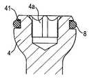
도 3a, 도 3b 및 도 3c에 도시된 바와 같이, 헤드(4)는 평탄한 자유 단부를 갖고 이 평탄한 자유 단부에 도구용 오목부(4a)를 갖는 구형 세그먼트의 형태이다. 환형 홈(41)이 최대 직경 위의 위치에 자유 단부를 향한 방향으로 제공된다. 환형 홈(41)의 단면은 도 6a로부터 알 수 있는 바와 같이 개방측이 실질적으로 사다리부꼴이다. 환형 홈(41)은 링(8)의 수용하는 역할을 한다. 환형 홈(41)의 바닥은 나사 부재(2)의 축과 실질적으로 동축이다. 환형 홈(41)의 바닥의 엣지는 라운드 될 수 있다. 헤드(4)의 자유 단부는 또한 평탄한 형태와 다를 수 있다.As shown in Figs. 3a, 3b and 3c, the
수용부(5)는 대략적으로 원통형인 단일체 부품이며, 상단(51)과 바닥단(52)을 갖는다. 상단(51)으로부터 바닥단(52)으로 연장되는 통로가 동축 구멍(53)에 의해 형성되고, 나사 부재(2)의 헤드를 수용하기 위한 시트부(54)가 그 뒤를 잇는다. 시트부(54)는 바닥단(52)에 개구(55)를 갖고, 이를 통해 나사 부재(2)의 샤프트(3)가 연장된다. 시트부(54)는 구형인 것으로 도시되지만, 이것은 테이퍼지거나, 헤드(4)를 수용부(5)에 대해 피봇 동작을 할 수 있도록 수용할 수 있는 모든 다른 형태를 가질 수 있다. 상단(51)에는 대략 U-형의 오목부(56)가 제공되며, 오목부(56)에 의해 로드(20)를 수용하기 위한 채널의 측벽인 2개의 자유 다리부(57, 58)가 형성된다. 암나사부(59)가 내부 나사부(7)와 상호 작용을 위해 다리부에 제공된다.The
수용부(5)는 상단(51)으로부터의 거리보다 작은 바닥단(52)으로부터의 거리에, 전술한 방식으로 크링핑을 위한 동축 구멍(53)의 내벽으로부터의 소정 거리로 외부면으로부터 연장된 크림핑 구멍을 형성하는 2개의 블라인드 홀(500a, 500b)을 더 갖는다. 블라인드 홀(500a, 500b)은 서로에 대해 180°어긋나게 배치되고, U-형 오목부(56)에 의해 형성된 채널에 대해 90°로 배치된다. 블라인드 홀(500a, 500b)은 동축 구멍(53)의 구멍 축선에 대해 수직으로 정렬된다. 블라인드 홀(500a, 500b)의 폐쇄 단부과 수용부(5)의 동축 구멍(53) 사이에 있는 수용부(5)의 부분은 변형 가능한 부분으로 구성된다.The
가압 요소(6)는 단일체로 형성된다. 실질적으로 원통형 구성이며, 수용부(5)의 구멍(53) 내부의 축 방향으로 이동할 수 있는 외경을 갖는다. 가압 요소(6)는 상단(61)과 바닥단(62)을 갖는다. 가압 요소(6)가 수용부(5) 안으로 삽입된 때, 바닥단(62)은 나사 요소(2)의 헤드(4)를 향한다. 상단(61)에는 로드(20)를 내부에 수용하도록 채널을 형성한 2개의 자유 다리부(65, 66)에 의해 U-형 오목부(64)가 제공된다. 또한, 가압 요소(6)는 도구(도시 생략)로 나사 헤드(4)에 접근하기 위한 동축 구멍(67)을 포함한다. 도 1 및 도 2에 도시된 바와 같이, 가압 요소(6)는 수용부(5)의 U-형 오목부(56)와 가압 요소(6)의 U-형 오목부(64)가 정렬되도록 수용부(5) 내에 배치된 중실형 부재이다.The
가압 요소(6)는 수용부(5)의 크림핑 구멍(500a, 500b)에 상응하는 2개의 크림핑 구멍을 포함하며, 크림핑 후에 가압 요소(6)는 회전으로 정렬된 위치와 헤드(4)에 약간의 예하중을 가할 수 있는 축 위치에 유지된다.The
도 4a 내지 도 4d는 링(8)을 보여준다. 도 4c에 도시된 바와 같이, 링(8)은 폐쇄 링이다. 변형되지 않은 상태에서 대략적으로 원형 단면을 갖는다. 링(8)은 탄성 변형 가능한 플라스틱 재료 예컨대 신체친화적 엘라스토머로 만든다. 엘라스토머 예컨대 UHMWPE(초고분자량 폴리에틸렌), 실리콘, PCU, SIBS 또는 그 조합을 사용할 수 있다. 뼈 고정 장치(1)의 다른 부분은 신체친화적 재료, 예컨대 티타늄과 같은 신체친화적 금속, 예컨대 니티놀(Nitinol)과 같은 신체친화적 금속 합금, 또는 예컨대 PEEK와 같은 신체친화적 플라스틱 재료, 또는 그 조합으로 이루어진다.4A-4D show the
링(8)은 링이 환형 홈(41) 안으로 삽입될 때 실질적으로 변형되지 않고 환형 홈(41) 밖으로 약간 돌출하게 되는 크기이다. 환형 홈(41)의 단면이 사다리부꼴이므로, 환형 홈(41)은 가압 요소(6)에 의해 링(8)에 하중이 가해질 때 링(8)의 변형을 위한 공간을 제공한다.The
도 5a에 도시된 조립된 상태에서, 헤드(4)는 시트(54)에 위치되고, 가압 요소(6)는 헤드(4)의 상부에 배치된다. 가압 요소(6)의 자유 다리부(65, 66)의 높이는 로드가 삽입되어 채널의 바닥에 안착될 때 자유 다리부(65, 66)가 로드(20) 위로 연장되지 않도록 설정된다. 도 5a와 도 5b에 도시된 가압 요소(6)는 크림핑 구멍(500a, 500b, 600a, 600b)을 통해 크링핌하는 것에 의해 가압 요소(6)와 수용부(5)를 연결함으로써 정해지는 제1 위치를 차지할 수 있으며, 제1 위치에서 링(8)과 가압 요소(6)는 가압 요소(6)가 링(8)을 통해 헤드(4)-헤드(4)는 헤드(4)의 고정 전에 마찰에 의해 소정의 각도 위치에 유지됨-에 예하중력을 가하는 방식으로 상호 작용한다. 힘은 내부 나사부(7), 로드(20), 가압 요소(6) 및 링(8)을 통해 헤드(4)에 가해진다. 실질적으로 원형 단면을 갖는 링(8)은 그 단면이 이 제1 위치에서 실질적으로 타원형이도록 변형된다. 변형에 의해, 링(8)은 헤드(4)가 각도 위치에 유지되도록 가압 요소(6)에 대해 반대방향 힘을 가한다. 이 위치는 마찰력을 넘어서도록 나사 부재(2)에 힘을 가하는 것에 의해 조절될 수 있다. 가압 요소(6)는 헤드(4)가 내부 나사부(7) 내의 나사 회전에 의해 고정되는 제2 위치도 역시 차지할 수 있다. 더욱이, 가압 요소(6)는 헤드(4)가 자유로이 피봇 동작할 수 있는 제3 위치를 차지할 수 있다. 이들 위치에서, 가압 요소(6)는 링(8)과 실질적으로 마찰 접촉하지 않는다. 링(8)의 크기와 환형 홈(41)의 크기를 선택하는 것에 의해 원하는 마찰력을 얻을 수 있다.In the assembled state shown in FIG. 5A, the
도 6a 내지 도 6d는 뼈 고정 요소(2)의 조립체를 보여준다. 링(8)은 뼈 고정 요소(2)의 헤드에 장착되어 도 6b와 도 6c에 도시된 환형 홈(41)에 수용되어 있다. 도 6d는 가압 요소가 장착된 뼈 고정 요소(2)를 보여준다. 가압 요소(6)를 샤프트(3)의 방향으로 아래로 이동시킬 때, 헤드(4)는 마찰에 의해 각도 위치에 유지된다.6a to 6d show the assembly of the
사용시, 먼저 뼈 고정 장치(1)는 헤드(4)가 임시로 마찰 체결된 제1 위치에 가압 요소가 있는 예비 조립된 상태로 제공된다. 통상 여러 개의 뼈 고정 장치(1)가 필요하다. 그 다음 나사 부재(2)들을 뼈 또는 척추뼈에 나사 삽입한 후 각각의 수용부(5)가 로드(20)의 삽입을 위한 정확한 배향을 가질 때까지 체결력을 넘어서도록 힘을 가해 수용부(5)들을 피봇 동작시킨다. 임시 체결에 의해, 수용부(5)는 이 각도 위치에 유지된다. 뼈 고정 장치(1)를 연결하는 로드(20)를 삽입하고, 가압 요소(6)를 하향 이동시키도록 내부 나사(7)를 조여서 수용부(5)에 대한 나사 부재(2)의 각도 위치가 고정되도록 헤드(4)를 고정시킨다. 그런 다음 내부 나사부(7)에 의해 로드(20)를 고정시킨다.In use, the bone fixation device 1 is first provided in a pre-assembled state with the pressing element in a first position where the
고정 요소로는 모든 종류의 고정 요소가 사용될 수 있고 수용부와 조합될 수 있다. 이들 고정 요소는 예컨대 서로 다른 길이, 서로 다른 직경을 갖는 나사부, 캐뉼러형(cannulated) 나사부, 서로 다른 나사를 갖는 나사부, 네일 등이다. 헤드와 샤프트는 서로 연결될 수 있는 개별적인 부품일 수 있다.As the fixing element, all kinds of fixing elements can be used and combined with the receiving portion. These fastening elements are, for example, threads of different lengths, diameters different, cannulated threads, threads with different screws, nails and the like. The head and shaft may be separate parts that can be connected to each other.
다양한 종류의 수용부가 특히 서로 다른 고정 장치에 사용될 수 있다. 예컨대 로드와 헤드를 동시에 고정하는 내부 나사부와 같은 단일체 고정 장치 대신에 외부 나사부와 내부 나사부를 갖는 2-부품 고정 장치를 사용할 수 있다. 이 경우 가압 요소는 다리부들이 로드 위로 연장된 U-형 오목부를 갖는다. 2-부품 고정 장치에 의해, 헤드와 로드는 독립적으로 고정될 수 있다. 더욱이, 외부 너트, 외부 캡, 체결식(bayonet) 고정 장치 또는 다른 장치들도 역시 가능하다. 수용부의 형태는 예시된 실시 형태로 제한되지 않는다. 예컨대 수용부는 나사 부재의 더 큰 피봇 각을 일측에 허용하기 위해 대칭의 단부를 가질 수 있다.Various types of receptacles can be used, in particular in different fastening devices. Instead of a monolithic fixing device, such as, for example, an internal thread that secures the rod and the head simultaneously, a two-part fixing device having an external thread and an internal thread can be used. In this case the pressing element has a U-shaped recess with legs extending over the rod. By means of a two-part fastening device, the head and the rod can be fixed independently. Moreover, external nuts, outer caps, bayonet fasteners or other devices are also possible. The shape of the receiver is not limited to the illustrated embodiment. For example, the receptacle may have a symmetrical end to allow on one side a larger pivot angle of the screw member.
변형례에서, 환형 홈은 헤드에 제공되지 않고 링을 수용하기 위한 수용부의 내벽에 제공된다. 링과 헤드는 헤드(4)의 고정 전에 마찰에 의해 각도 위치에 유지되는 헤드에 가압 요소가 링을 통해 예하중력을 가하도록 상호 작용한다.In a variant, the annular groove is not provided in the head but provided in the inner wall of the receiving portion for receiving the ring. The ring and the head interact with the pressing element to preload through the ring to the head which is held in angular position by friction before fixing the
또 다른 변형례에서, 예컨대 PEEK와 같은 비-신축성 재료로 만든 링이 제공된다. 그러한 링은 마찰식 접촉을 확보하도록 헤드의 표면보다 약간 더 큰 크기만을 가질 수 있다. 더욱이, 링의 단면은 또한 실질적으로 타원형, 직사각형 등일 수 있거나, 링의 원주에 걸쳐 달라질 수 있다.In another variant, a ring made of a non-stretchable material such as PEEK is provided. Such a ring may only have a size slightly larger than the surface of the head to ensure frictional contact. Moreover, the cross section of the ring may also be substantially oval, rectangular, or the like, or may vary over the circumference of the ring.
하나의 단일 링을 사용하는 대신에, 헤드 또는 가압 요소의 환형 홈 안에 배치되는 하나 또는 여러 신축성 요소를 사용하는 것도 역시 가능하다. 이들 요소 또는 링의 단면은 각각 다양할 수 있다.Instead of using one single ring, it is also possible to use one or several flexible elements arranged in the annular groove of the head or the pressing element. The cross section of these elements or rings may each vary.
추가의 변형례에서, 수용부는 바닥단으로부터 나사 요소를 도입할 수 있도록 구성된다.In a further variant, the receptacle is configured to be able to introduce the screw element from the bottom end.
Claims (10)
Translated fromKorean뼈 속에 고정되는 샤프트(3)와 헤드(4)를 갖는 고정 요소(2)와;
상단(51), 바닥단(52), 로드(20)를 안에 수용하는 오목부(56), 상기 상단(51)으로부터 바닥단(52)의 방향으로 연장된 동축 구멍(53) 및 상기 헤드(4)를 상기 바닥단(52) 가까이에서 수용하는 시트부(54)를 갖는 수용부(5)와;
상기 구멍(53) 내부에서 이동 가능한 가압 요소(6)와;
상기 헤드(4)와 상기 가압 요소(6) 사이에 배치된 폴리머 재료로 된 요소(8)
를 포함하며,
상기 헤드(4)는 상기 수용부(5)에 대해 피봇 동작 가능하며, 상기 가압 요소(6)를 통해 상기 헤드(4)에 압력을 가함으로써 미리 정해진 각도로 고정될 수 있으며,
상기 가압 요소(6)는 상기 헤드(4)가 상기 헤드(4)의 고정 전에 마찰에 의해 미리 정해진 각도 위치에 유지된 상태에서 상기 요소(8)와 상기 가압 요소(6)가 직접 접촉하여 상기 가압 요소(6)가 상기 요소(8)를 통하여 상기 헤드(6)에 예하중력을 가하게 되는 제1 위치를 취할 수 있는 것을 특징으로 하는 뼈 고정 장치.As the bone fixation device 1:
A fixing element 2 having a shaft 3 and a head 4 fixed in the bone;
The upper end 51, the bottom end 52, the recess 56 accommodating the rod 20 therein, the coaxial hole 53 extending from the upper end 51 in the direction of the bottom end 52 and the head ( A receiving portion 5 having a sheet portion 54 for receiving 4) near the bottom end 52;
A pressurizing element (6) moveable within the hole (53);
Element 8 of polymeric material disposed between the head 4 and the pressing element 6
Including;
The head 4 is pivotable with respect to the receiving portion 5 and can be fixed at a predetermined angle by applying pressure to the head 4 via the pressing element 6,
The pressing element 6 is in direct contact with the element 8 and the pressing element 6 in a state where the head 4 is held at a predetermined angular position by friction before fixing the head 4. Bone fixation device, characterized in that the pressing element (6) can take a first position to apply a preload force to the head (6) through the element (8).
Applications Claiming Priority (4)
| Application Number | Priority Date | Filing Date | Title |
|---|---|---|---|
| US201061426776P | 2010-12-23 | 2010-12-23 | |
| US61/426,776 | 2010-12-23 | ||
| EP10196880.8 | 2010-12-23 | ||
| EP10196880.8AEP2468198B1 (en) | 2010-12-23 | 2010-12-23 | Bone anchoring device |
Publications (1)
| Publication Number | Publication Date |
|---|---|
| KR20120072322Atrue KR20120072322A (en) | 2012-07-03 |
Family
ID=43927781
Family Applications (1)
| Application Number | Title | Priority Date | Filing Date |
|---|---|---|---|
| KR1020110138379AWithdrawnKR20120072322A (en) | 2010-12-23 | 2011-12-20 | Bone anchoring device |
Country Status (7)
| Country | Link |
|---|---|
| US (4) | US10433877B2 (en) |
| EP (1) | EP2468198B1 (en) |
| JP (1) | JP5917905B2 (en) |
| KR (1) | KR20120072322A (en) |
| CN (1) | CN102525620B (en) |
| ES (1) | ES2461843T3 (en) |
| TW (1) | TW201225903A (en) |
Families Citing this family (52)
| Publication number | Priority date | Publication date | Assignee | Title |
|---|---|---|---|---|
| US7833250B2 (en) | 2004-11-10 | 2010-11-16 | Jackson Roger P | Polyaxial bone screw with helically wound capture connection |
| US7377923B2 (en) | 2003-05-22 | 2008-05-27 | Alphatec Spine, Inc. | Variable angle spinal screw assembly |
| US8366753B2 (en) | 2003-06-18 | 2013-02-05 | Jackson Roger P | Polyaxial bone screw assembly with fixed retaining structure |
| US7766915B2 (en) | 2004-02-27 | 2010-08-03 | Jackson Roger P | Dynamic fixation assemblies with inner core and outer coil-like member |
| US8926670B2 (en) | 2003-06-18 | 2015-01-06 | Roger P. Jackson | Polyaxial bone screw assembly |
| US7776067B2 (en) | 2005-05-27 | 2010-08-17 | Jackson Roger P | Polyaxial bone screw with shank articulation pressure insert and method |
| US8926672B2 (en) | 2004-11-10 | 2015-01-06 | Roger P. Jackson | Splay control closure for open bone anchor |
| US8444681B2 (en) | 2009-06-15 | 2013-05-21 | Roger P. Jackson | Polyaxial bone anchor with pop-on shank, friction fit retainer and winged insert |
| US9216041B2 (en) | 2009-06-15 | 2015-12-22 | Roger P. Jackson | Spinal connecting members with tensioned cords and rigid sleeves for engaging compression inserts |
| US9980753B2 (en) | 2009-06-15 | 2018-05-29 | Roger P Jackson | pivotal anchor with snap-in-place insert having rotation blocking extensions |
| US9168069B2 (en) | 2009-06-15 | 2015-10-27 | Roger P. Jackson | Polyaxial bone anchor with pop-on shank and winged insert with lower skirt for engaging a friction fit retainer |
| US7901437B2 (en) | 2007-01-26 | 2011-03-08 | Jackson Roger P | Dynamic stabilization member with molded connection |
| US8475498B2 (en) | 2007-01-18 | 2013-07-02 | Roger P. Jackson | Dynamic stabilization connecting member with cord connection |
| US10383660B2 (en) | 2007-05-01 | 2019-08-20 | Roger P. Jackson | Soft stabilization assemblies with pretensioned cords |
| US8979904B2 (en) | 2007-05-01 | 2015-03-17 | Roger P Jackson | Connecting member with tensioned cord, low profile rigid sleeve and spacer with torsion control |
| US8007522B2 (en) | 2008-02-04 | 2011-08-30 | Depuy Spine, Inc. | Methods for correction of spinal deformities |
| CN103826560A (en) | 2009-06-15 | 2014-05-28 | 罗杰.P.杰克逊 | Polyaxial Bone Anchor with Socket Stem and Winged Inserts with Friction Fit Compression Collars |
| US11229457B2 (en) | 2009-06-15 | 2022-01-25 | Roger P. Jackson | Pivotal bone anchor assembly with insert tool deployment |
| US9668771B2 (en) | 2009-06-15 | 2017-06-06 | Roger P Jackson | Soft stabilization assemblies with off-set connector |
| US11464549B2 (en) | 2009-06-15 | 2022-10-11 | Roger P. Jackson | Pivotal bone anchor assembly with horizontal tool engagement grooves and insert with upright arms having flared outer portions |
| EP2485654B1 (en) | 2009-10-05 | 2021-05-05 | Jackson P. Roger | Polyaxial bone anchor with non-pivotable retainer and pop-on shank, some with friction fit |
| AU2011299558A1 (en) | 2010-09-08 | 2013-05-02 | Roger P. Jackson | Dynamic stabilization members with elastic and inelastic sections |
| AU2011324058A1 (en)* | 2010-11-02 | 2013-06-20 | Roger P. Jackson | Polyaxial bone anchor with pop-on shank and pivotable retainer |
| EP2659845A1 (en) | 2010-12-27 | 2013-11-06 | Biedermann Technologies GmbH & Co. KG | Polyaxial bone anchoring device |
| JP5865479B2 (en)* | 2011-03-24 | 2016-02-17 | ロジャー・ピー・ジャクソン | Multiaxial bone anchor with compound joint and pop-mounted shank |
| US8911479B2 (en) | 2012-01-10 | 2014-12-16 | Roger P. Jackson | Multi-start closures for open implants |
| EP2837347B1 (en) | 2012-01-30 | 2018-10-03 | Biedermann Technologies GmbH & Co. KG | Bone anchoring device |
| FR2993170B1 (en)* | 2012-07-12 | 2015-05-08 | Clariance | DEVICE FOR FRICTION OF A POLY AXIAL SCREW WITH A SPHERICAL HEAD |
| US9782204B2 (en) | 2012-09-28 | 2017-10-10 | Medos International Sarl | Bone anchor assemblies |
| US8911478B2 (en) | 2012-11-21 | 2014-12-16 | Roger P. Jackson | Splay control closure for open bone anchor |
| US10058354B2 (en) | 2013-01-28 | 2018-08-28 | Roger P. Jackson | Pivotal bone anchor assembly with frictional shank head seating surfaces |
| US8852239B2 (en) | 2013-02-15 | 2014-10-07 | Roger P Jackson | Sagittal angle screw with integral shank and receiver |
| US10342582B2 (en) | 2013-03-14 | 2019-07-09 | DePuy Synthes Products, Inc. | Bone anchor assemblies and methods with improved locking |
| US9724145B2 (en) | 2013-03-14 | 2017-08-08 | Medos International Sarl | Bone anchor assemblies with multiple component bottom loading bone anchors |
| US9259247B2 (en) | 2013-03-14 | 2016-02-16 | Medos International Sarl | Locking compression members for use with bone anchor assemblies and methods |
| US9775660B2 (en)* | 2013-03-14 | 2017-10-03 | DePuy Synthes Products, Inc. | Bottom-loading bone anchor assemblies and methods |
| US9566092B2 (en) | 2013-10-29 | 2017-02-14 | Roger P. Jackson | Cervical bone anchor with collet retainer and outer locking sleeve |
| US9717533B2 (en) | 2013-12-12 | 2017-08-01 | Roger P. Jackson | Bone anchor closure pivot-splay control flange form guide and advancement structure |
| US9451993B2 (en) | 2014-01-09 | 2016-09-27 | Roger P. Jackson | Bi-radial pop-on cervical bone anchor |
| US9597119B2 (en) | 2014-06-04 | 2017-03-21 | Roger P. Jackson | Polyaxial bone anchor with polymer sleeve |
| US10064658B2 (en) | 2014-06-04 | 2018-09-04 | Roger P. Jackson | Polyaxial bone anchor with insert guides |
| US9833263B2 (en)* | 2015-04-13 | 2017-12-05 | Medos International Sarl | Bone anchor assemblies with orientation indicator |
| CN108697445B (en) | 2016-02-26 | 2022-04-19 | 美多斯国际有限公司 | Polyaxial bone fixation element |
| US11026730B2 (en) | 2017-05-10 | 2021-06-08 | Medos International Sarl | Bone anchors with drag features and related methods |
| US10610265B1 (en) | 2017-07-31 | 2020-04-07 | K2M, Inc. | Polyaxial bone screw with increased angulation |
| EP3766443B1 (en) | 2019-07-18 | 2023-02-15 | Biedermann Technologies GmbH & Co. KG | Bone anchoring device |
| EP3871624B1 (en) | 2020-02-25 | 2023-07-19 | Biedermann Technologies GmbH & Co. KG | Bone anchoring device |
| USD956233S1 (en)* | 2020-04-24 | 2022-06-28 | Solco Biomedical Co., Ltd. | Cervical screw |
| WO2021263088A1 (en) | 2020-06-26 | 2021-12-30 | K2M, Inc. | Modular head assembly |
| WO2022108875A1 (en) | 2020-11-19 | 2022-05-27 | K2M, Inc. | Modular head assembly for spinal fixation |
| US12364515B2 (en) | 2021-03-05 | 2025-07-22 | Medos International Sàrl | Multi-feature polyaxial screw |
| WO2022184797A1 (en) | 2021-03-05 | 2022-09-09 | Medos International Sarl | Selectively locking polyaxial screw |
Family Cites Families (26)
| Publication number | Priority date | Publication date | Assignee | Title |
|---|---|---|---|---|
| DE19720782B4 (en)* | 1997-05-17 | 2004-12-09 | Synthes Ag Chur, Chur | Device for connecting a side member to a pedicle screw |
| US6248105B1 (en) | 1997-05-17 | 2001-06-19 | Synthes (U.S.A.) | Device for connecting a longitudinal support with a pedicle screw |
| US6113601A (en)* | 1998-06-12 | 2000-09-05 | Bones Consulting, Llc | Polyaxial pedicle screw having a loosely coupled locking cap |
| US7001389B1 (en)* | 2002-07-05 | 2006-02-21 | Navarro Richard R | Fixed and variable locking fixation assembly |
| US7087057B2 (en)* | 2003-06-27 | 2006-08-08 | Depuy Acromed, Inc. | Polyaxial bone screw |
| WO2006047711A2 (en)* | 2004-10-25 | 2006-05-04 | Alphaspine, Inc. | Pedicle screw systems and methods |
| US8353939B2 (en)* | 2005-01-12 | 2013-01-15 | Warsaw Orthopedic, Inc. | Anchor retaining mechanisms for bone plates |
| US7445627B2 (en)* | 2005-01-31 | 2008-11-04 | Alpinespine, Llc | Polyaxial pedicle screw assembly |
| US10076361B2 (en)* | 2005-02-22 | 2018-09-18 | Roger P. Jackson | Polyaxial bone screw with spherical capture, compression and alignment and retention structures |
| EP1741396B1 (en) | 2005-07-08 | 2009-09-23 | BIEDERMANN MOTECH GmbH | Bone anchoring device |
| US20070118117A1 (en)* | 2005-10-20 | 2007-05-24 | Ebi, L.P. | Bone fixation assembly |
| US8057519B2 (en)* | 2006-01-27 | 2011-11-15 | Warsaw Orthopedic, Inc. | Multi-axial screw assembly |
| US20080015597A1 (en)* | 2006-04-28 | 2008-01-17 | Whipple Dale E | Large diameter bone anchor assembly |
| US7806913B2 (en)* | 2006-08-16 | 2010-10-05 | Depuy Spine, Inc. | Modular multi-level spine stabilization system and method |
| US7867258B2 (en) | 2006-10-17 | 2011-01-11 | Warsaw Orthopedic, Inc. | Multi-axial bone attachment member |
| ES2373770T3 (en)* | 2006-11-22 | 2012-02-08 | Biedermann Motech Gmbh | BONE ANCHORAGE DEVICE. |
| WO2008118295A2 (en)* | 2007-03-26 | 2008-10-02 | Laszlo Garamszegi | Bottom-loading pedicle screw assembly |
| EP2265202B1 (en)* | 2008-04-22 | 2012-08-29 | Synthes GmbH | Bone fixation element with reduction tabs |
| ES2390174T3 (en)* | 2008-07-24 | 2012-11-07 | Mitsubishi Electric Corporation | Train braking device |
| EP2160988B1 (en)* | 2008-09-04 | 2012-12-26 | Biedermann Technologies GmbH & Co. KG | Rod-shaped implant in particular for stabilizing the spinal column and stabilization device including such a rod-shaped implant |
| ES2375879T3 (en)* | 2008-12-23 | 2012-03-07 | Biedermann Motech Gmbh | RECEPTION AREA OF A ROD FOR COUPLING THE ROD IN AN BONE ANCHORAGE ELEMENT AND BONE ANCHORAGE DEVICE WITH SUCH RECEPTION AREA. |
| US8361123B2 (en)* | 2009-10-16 | 2013-01-29 | Depuy Spine, Inc. | Bone anchor assemblies and methods of manufacturing and use thereof |
| WO2012030712A1 (en)* | 2010-08-30 | 2012-03-08 | Zimmer Spine, Inc. | Polyaxial pedicle screw |
| AU2011324058A1 (en)* | 2010-11-02 | 2013-06-20 | Roger P. Jackson | Polyaxial bone anchor with pop-on shank and pivotable retainer |
| US8734495B2 (en)* | 2012-01-18 | 2014-05-27 | Globus Medical, Inc. | Securing fasteners |
| EP3766443B1 (en)* | 2019-07-18 | 2023-02-15 | Biedermann Technologies GmbH & Co. KG | Bone anchoring device |
- 2010
- 2010-12-23ESES10196880.8Tpatent/ES2461843T3/enactiveActive
- 2010-12-23EPEP10196880.8Apatent/EP2468198B1/enactiveActive
- 2011
- 2011-12-20CNCN201110428639.6Apatent/CN102525620B/ennot_activeExpired - Fee Related
- 2011-12-20TWTW100147235Apatent/TW201225903A/enunknown
- 2011-12-20KRKR1020110138379Apatent/KR20120072322A/ennot_activeWithdrawn
- 2011-12-20JPJP2011278133Apatent/JP5917905B2/ennot_activeExpired - Fee Related
- 2011-12-23USUS13/336,708patent/US10433877B2/enactiveActive
- 2019
- 2019-08-27USUS16/552,661patent/US11123109B2/enactiveActive
- 2021
- 2021-08-16USUS17/403,343patent/US11992243B2/enactiveActive
- 2024
- 2024-05-03USUS18/654,633patent/US20240350177A1/enactivePending
Also Published As
| Publication number | Publication date |
|---|---|
| CN102525620A (en) | 2012-07-04 |
| US11123109B2 (en) | 2021-09-21 |
| EP2468198B1 (en) | 2014-02-19 |
| EP2468198A1 (en) | 2012-06-27 |
| US20240350177A1 (en) | 2024-10-24 |
| JP5917905B2 (en) | 2016-05-18 |
| US20220031368A1 (en) | 2022-02-03 |
| US20120165881A1 (en) | 2012-06-28 |
| ES2461843T3 (en) | 2014-05-21 |
| US11992243B2 (en) | 2024-05-28 |
| TW201225903A (en) | 2012-07-01 |
| JP2012130697A (en) | 2012-07-12 |
| CN102525620B (en) | 2015-08-05 |
| US10433877B2 (en) | 2019-10-08 |
| US20200054364A1 (en) | 2020-02-20 |
Similar Documents
| Publication | Publication Date | Title |
|---|---|---|
| KR20120072322A (en) | Bone anchoring device | |
| US12193712B2 (en) | Bone anchoring device | |
| US11963698B2 (en) | Polyaxial bone anchoring device | |
| US9333016B2 (en) | Polyaxial bone anchoring device | |
| US8636781B2 (en) | Receiving part for receiving a rod for coupling the rod to a bone anchoring element and a bone anchoring device with such a receiving part | |
| KR20120074219A (en) | Polyaxial bone anchoring device | |
| US20100249846A1 (en) | Variable height, multi-axial bone screw assembly | |
| KR20120065236A (en) | Receiving part for receiving a rod for coupling the rod to a bone anchoring element and a bone anchoring device | |
| KR20120065234A (en) | Receiving part for receiving a rod for coupling the rod to a bone anchoring element and bone anchoring device with such a receiving part |
Legal Events
| Date | Code | Title | Description |
|---|---|---|---|
| PA0109 | Patent application | Patent event code:PA01091R01D Comment text:Patent Application Patent event date:20111220 | |
| PG1501 | Laying open of application | ||
| PC1203 | Withdrawal of no request for examination | ||
| WITN | Application deemed withdrawn, e.g. because no request for examination was filed or no examination fee was paid |