KR20120064532A - Receiver of pulse radar - Google Patents
Receiver of pulse radarDownload PDFInfo
- Publication number
- KR20120064532A KR20120064532AKR1020100125810AKR20100125810AKR20120064532AKR 20120064532 AKR20120064532 AKR 20120064532AKR 1020100125810 AKR1020100125810 AKR 1020100125810AKR 20100125810 AKR20100125810 AKR 20100125810AKR 20120064532 AKR20120064532 AKR 20120064532A
- Authority
- KR
- South Korea
- Prior art keywords
- pulse
- transmission
- pll
- receiver
- trigger signal
- Prior art date
- Legal status (The legal status is an assumption and is not a legal conclusion. Google has not performed a legal analysis and makes no representation as to the accuracy of the status listed.)
- Ceased
Links
Images


Classifications
- G—PHYSICS
- G01—MEASURING; TESTING
- G01S—RADIO DIRECTION-FINDING; RADIO NAVIGATION; DETERMINING DISTANCE OR VELOCITY BY USE OF RADIO WAVES; LOCATING OR PRESENCE-DETECTING BY USE OF THE REFLECTION OR RERADIATION OF RADIO WAVES; ANALOGOUS ARRANGEMENTS USING OTHER WAVES
- G01S7/00—Details of systems according to groups G01S13/00, G01S15/00, G01S17/00
- G01S7/02—Details of systems according to groups G01S13/00, G01S15/00, G01S17/00 of systems according to group G01S13/00
- G01S7/28—Details of pulse systems
- G01S7/285—Receivers
- G01S7/292—Extracting wanted echo-signals
Landscapes
- Engineering & Computer Science (AREA)
- Computer Networks & Wireless Communication (AREA)
- Physics & Mathematics (AREA)
- General Physics & Mathematics (AREA)
- Radar, Positioning & Navigation (AREA)
- Remote Sensing (AREA)
- Radar Systems Or Details Thereof (AREA)
Abstract
Description
Translated fromKorean본 발명은 펄스레이더 수신기에 관한 것으로서, 보다 상세하게는 송신펄스와 임의의 차이를 갖는 샘플링 주파수를 생성하여 반사파를 샘플링하여 수신함으로써 높은 거래분해능을 갖도록 한 펄스레이더 수신기에 관한 것이다.
The present invention relates to a pulse radar receiver, and more particularly, to a pulse radar receiver having high transaction resolution by generating a sampling frequency having a random difference from a transmission pulse and sampling and receiving a reflected wave.
일반적으로 레이더(RADAR : Radio Detection And Ranging)는 인간의 가시거리 한계를 초월하여 원거리에 있는 물체의 존재를 탐지하는 센서로서, 펄스레이더의 경우 레이더 송신기에서 송신펄스를 송신펄스반복주파수로 송신하여 목표물에 맞고 되돌아오는 에코신호를 수신기가 수신 및 판별하여 타겟의 위치, 크기정보를 얻게 된다.In general, a radar (Radar Detection And Ranging) is a sensor that detects the presence of a remote object beyond the visible range of a human being. In the case of a pulse radar, a radar transmitter transmits a transmission pulse at a transmission pulse repetition frequency. The receiver receives and discriminates the echo signal that is returned from the receiver and obtains the position and size information of the target.
이러한 레이더 기술의 응용으로 군용 감시레이더, 민수용 자동차 레이더 및 환자 모니터링 레이더 등이 있다.
Applications of such radar technologies include military surveillance radars, civil vehicle radars, and patient monitoring radars.
위에서 설명한 기술은 본 발명이 속하는 기술분야의 배경기술을 의미하며, 종래기술을 의미하는 것은 아니다.
The technology described above refers to the background of the technical field to which the present invention belongs, and does not mean the prior art.
이와 같은 펄스레이더 수신기는 하나의 송신펄스로부터 펄스의 존재유무를 판단하여 송신펄스와 수신펄스간의 시간간격으로부터 거리를 구하기 때문에 펄스폭에 의하여 거리 해상도가 결정됨에 따라 높은 해상도 구현에 한계가 있는 문제점이 있다.Since the pulse radar receiver determines the presence or absence of a pulse from a single transmission pulse and obtains a distance from the time interval between the transmission pulse and the reception pulse, there is a problem in that a high resolution is limited as the distance resolution is determined by the pulse width. have.
따라서, 이러한 한계를 극복하기 위해 다수의 송신펄스를 수신하여 측정하는 수신기법이 있으나 이 또한 수신펄스의 신호대 잡음지수(SNR)만 높아질 뿐 높은 해상도 구현에는 한계가 있다.Therefore, in order to overcome this limitation, there is a receiver method for receiving and measuring a plurality of transmission pulses, but this also increases the signal-to-noise index (SNR) of the reception pulses, and there is a limitation in implementing high resolution.
또한, 레인지 게이팅(range gating) 방식의 경우에서는 레이더의 수신기에 지연기를 두어 지연값을 가변함으로 인해 특정 레인지에 대하여 타겟의 존재 유무를 판단할 수 있으나 펄스폭에 의하여 결정되는 레인지의 해상도를 높일 수 있는데 한계가 있는 문제점이 있다.In addition, in the range gating method, it is possible to determine the presence or absence of a target for a specific range by varying the delay value by placing a delay in the receiver of the radar, but the resolution of the range determined by the pulse width can be increased. There is a problem with limitations.
본 발명은 상기와 같은 문제점을 개선하기 위해 창작된 것으로서, 송신펄스와 임의의 차이를 갖는 샘플링 주파수를 생성하여 반사파를 샘플링하여 수신함으로써 높은 거래분해능을 갖도록 한 펄스레이더 수신기를 제공하는데 그 목적이 있다.
SUMMARY OF THE INVENTION The present invention has been made to solve the above problems, and an object thereof is to provide a pulse radar receiver having a high transaction resolution by sampling and receiving a reflected wave by generating a sampling frequency having a random difference from a transmission pulse. .
본 발명의 일 측면에 따른 펄스레이더 수신기는 송신펄스를 발생하기 위한 송신 트리거 신호를 분리하기 위한 파워스플리터; 파워스플리터에서 분리된 송신 트리거 신호와 분주비를 입력받아 샘플링 주파수를 발생시키는 PLL; 및 PLL에서 발생된 샘플링 주파수에 따라 수신안테나를 통해 수신되는 반사파를 샘플링하는 샘플러를 포함하는 것을 특징으로 한다.According to an aspect of the present invention, a pulse radar receiver includes: a power splitter for separating a transmission trigger signal for generating a transmission pulse; A PLL for receiving a transmission trigger signal and a division ratio separated from the power splitter and generating a sampling frequency; And a sampler for sampling the reflected wave received through the reception antenna according to the sampling frequency generated by the PLL.
본 발명에서 PLL은 분주비를 입력받기 위한 키입력부를 더 포함하는 것을 특징으로 한다.In the present invention, the PLL further includes a key input unit for receiving a division ratio.
본 발명은 수신안테나를 통해 수신된 반사파를 증폭하는 이득증폭기를 더 포함하는 것을 특징으로 한다.The invention further comprises a gain amplifier for amplifying the reflected wave received through the receiving antenna.
본 발명에서 샘플러는 AD컨버터인 것을 특징으로 한다.
Sampler in the present invention is characterized in that the AD converter.
상기한 바와 같이 본 발명은 송신펄스와 임의의 차이를 갖는 샘플링 주파수를 생성하여 반사파를 샘플링하여 수신함으로써 높은 거래분해능을 가질 수 있어 펄스폭에 의한 거리해상도가 제한되는 단점을 극복할 수 있을 뿐만 아니라 근거리에서 미세한 움직임을 측정하는데 사용될 수 있으므로 생체측정 레이더로 응용할 수 있다.
As described above, the present invention can generate a sampling frequency having a random difference from the transmission pulse, sample the reflected wave, and receive the high transaction resolution, thereby overcoming the disadvantage of limiting the distance resolution due to the pulse width. It can be used to measure microscopic movement at close range, making it a biometric radar.
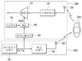
도 1은 본 발명의 일 실시예에 따른 펄스레이더 수신기를 나타낸 블록구성도이다.
도 2는 본 발명의 일 실시예에 따른 펄스레이더 수신기의 PLL을 구체적으로 나타낸 구성도이다.
도 3은 본 발명의 일 실시예에 따른 펄스레이더 수신기를 통해 수신하는 원리를 설명하기 위한 그래프이다.1 is a block diagram illustrating a pulse radar receiver according to an embodiment of the present invention.
2 is a diagram illustrating in detail a PLL of a pulse radar receiver according to an embodiment of the present invention.
3 is a graph illustrating a principle of receiving through a pulse radar receiver according to an embodiment of the present invention.
이하, 첨부된 도면을 참조하여 본 발명에 따른 펄스레이더 수신기의 일 실시예를 설명한다. 이 과정에서 도면에 도시된 선들의 두께나 구성요소의 크기 등은 설명의 명료성과 편의상 과장되게 도시되어 있을 수 있다. 또한, 후술되는 용어들은 본 발명에서의 기능을 고려하여 정의된 용어들로서 이는 사용자, 운용자의 의도 또는 관례에 따라 달라질 수 있다. 그러므로, 이러한 용어들에 대한 정의는 본 명세서 전반에 걸친 내용을 토대로 내려져야 할 것이다.Hereinafter, an embodiment of a pulse radar receiver according to the present invention will be described with reference to the accompanying drawings. In this process, the thickness of the lines or the size of the components shown in the drawings may be exaggerated for clarity and convenience of description. In addition, the terms described below are defined in consideration of the functions of the present invention, which may vary depending on the intention or custom of the user, the operator. Therefore, definitions of these terms should be made based on the contents throughout the specification.
도 1은 본 발명의 일 실시예에 따른 펄스레이더 수신기를 나타낸 블록구성도이고, 도 2는 본 발명의 일 실시예에 따른 펄스레이더 수신기의 PLL을 구체적으로 나타낸 구성도이다.1 is a block diagram illustrating a pulse radar receiver according to an embodiment of the present invention, and FIG. 2 is a block diagram illustrating a PLL of a pulse radar receiver according to an embodiment of the present invention.
도 1에 도시된 바와 같이 본 발명의 일 실시예에 따른 펄스레이더 수신기는 파워스플리터(60), PLL(40) 및 샘플러(10)를 포함한다.As shown in FIG. 1, a pulse radar receiver according to an embodiment of the present invention includes a
파워스플리터(60)는 송신 트리거 신호(Tx Trg)를 발생시키는 송신트리거 발생기(70)와 송신 트리거 신호를 입력받아 송신펄스를 발생시키는 펄스발생기(80)의 사이에서 송신 트리거 신호를 분리하여 PLL(40)로 출력한다.The
PLL(40)은 파워스플리터(60)에서 분리된 송신 트리거 신호(Tx Trg)와 키입력부(50)를 통해 사용자 입력한 분주비(m,n,p)를 입력받아 수신펄스를 샘플링하기 위한 샘플링 주파수(Rx Clk)를 발생시킨다.The
이때 PLL(40)은 도 2에 도시된 바와 같이 제 1내지 제 3분주기(41,42,46), 위상비교기(43), 루프필터(44), 전압제어발진기(45)를 포함한다. 그러나, 이와 같은 PLL의 구조는 본 발명의 범위를 한정하는 것은 아니며 송신펄스와 Δf차이의 샘플링 주파수(Rx Clk)를 발생시킬 수 있는 구조이면 어느 것이나 가능하다할 것이다.In this case, the
이와 같은 PLL(40)은 피드백 루프를 구성하여 입력신호인 송신 트리거 신호를 기준으로 위상이 고정된 루프를 구성한다.The
또한, 사용자로부터 분주비(m,n,p)를 입력받기 위한 키입력부(50)를 구비하여 송신 트리거 신호(Tx Trg)를 입력받아 송신펄스와 위상이 고정된 Δf차이의 샘플링 주파수(Rx Clk)를 발생시킨다. 이때 Δf는 사용자가 분주비를 통해 임의로 설정할 수 있다.In addition, a
예를 들어, 발진주파수가 100MHz의 전압제어발진기(45)를 사용하고, 제 1내지 제 3분주기(41,42,46)의 입력으로 m,n,p를 각각 5000, 4999, 10으로 입력할 경우 송신 트리거 발생기(70)에서 발생된 송신 트리거 신호(Tx Trg)의 주파수가 10MHz 일 때, PLL(40)에서 발생되는 샘플링 주파수(Rx Clk)는 송신펄스와 2kHz 만큼의 차이를 보이게 된다. 이는 시간영역에서 송신펄스의 반복주기와 약 20psec의 주기차이를 의미하며 거리 분해능으로는 6mm에 해당한다.For example, a voltage controlled
샘플러(10)는 AD 컨버터로써 PLL(40)에서 발생된 샘플링 주파수(Rx Clk)에 따라 수신안테나(30)를 통해 수신되는 반사파를 샘플링한다.The
또한, 수신안테나(30)를 통해 수신된 반사파를 증폭하는 이득증폭기(20)를 더 포함할 수 있다.
In addition, a
이와 같이 이루어진 펄스레이더 수신기의 동작을 설명하면 다음과 같다.Referring to the operation of the pulse radar receiver made as described above are as follows.
먼저, 펄스레이더는 펄스 송신기(300)에서 송신펄스를 목표물(100)에 방출하면, 반사되는 반사파를 펄스 수신기(200)에서 수신하여 목표물(100)의 위치 및 변위정보를 획득할 수 있다.First, when the pulse radar emits a transmission pulse from the
이를 좀더 구체적으로 설명하면 펄스 송신기(300)는 송신 트리거 발생기(70)에서 발생된 송신 트리거 신호(Tx Trg)를 입력받은 펄스발생기(80)에서 송신 트리거 신호(Tx Trg)와 동일한 주파수로 송신펄스를 발생시켜 송신안테나(90)를 통해 목표물(100)로 방출한다.In more detail, the
이렇게 목표물(100)에 방출된 송신펄스의 반사파를 펄스 수신기(200)에서 좁은 시간간격으로 수신하여 목표물(100)의 위치 및 변위에 대한 정보를 얻게 된다.As such, the reflected wave of the transmission pulse emitted to the
펄스 수신기(200)는 수신안테나(30)를 통해 수신되는 반사파를 저잡음 증폭기를 포함하는 이득증폭기(20)를 거쳐 증폭시킨 후 디지털 영역으로 신호를 바꾸어 주는 샘플러(10)를 거쳐 디지털 영역으로 신호를 변환한 후 디지털 영역에서 신호처리를 수행한다.The
이때, 수신된 다수의 반사파로부터 수신펄스를 샘플링하는 샘플링 주파수(Rx Clk)는 PLL(40)을 사용하여 송신펄스와 Δf(시간영역에서는 Δt) 차이를 갖도록 발생시킴으로써 좁은 시간간격(즉, 높은 거리분해능)으로 펄스를 수신할 수 있다.At this time, the sampling frequency (Rx Clk) for sampling the received pulse from the plurality of received reflected waves is generated to have a difference between the transmission pulse and Δf (Δt in the time domain) using the
PLL(40)은 사용자가 키입력부(50)를 통해 분주비를 정의함으로써 송신 트리거 발생기(70)에서 생성된 송신 트리거 신호(Tx Trg)를 파워스플리터(60)를 통해 입력받아 송신펄스와 Δf차이의 샘플링주파수(Rx Clk)를 발생시킨다.The
예를 들어, 목표물(100)은 정지한 사람이며 호흡으로 인해 호흡의 주기로 3cm의 변위가 몸통에서 발생하고 있다고 할 때 송신 트리거 발생기(70)에서 10MHz의 송신 트리거 신호(Tx Trg)를 발생시키면, 100nsec의 주기로 펄스폭 0.5nsec의 송신펄스가 목표물(100)로 방출된다.For example, if the
그러면, 펄스 수신기(200)의 PLL(40)은 발진주파수 100MHz의 전압제어발진기(45)를 사용하고 제 1내지 제 3분주기(41,42,46)의 분주비(m,n,p)를 각각 5000, 4999, 10으로 입력받으면, 샘플링 주파수(Rx Clk)로써 송신펄스와 2kHz 차이나는 주파수를 샘플러(10)로 출력함으로써 샘플링하여 수신펄스를 얻게 된다.Then, the
이는 시간영역에서 약 20psec의 주기 차이를 의미하며 거리 분해능으로는 6mm에 해당하므로 호흡의 변위 3cm를 측정할 수 있게 된다.
This means a period difference of about 20 psec in the time domain. Since the distance resolution corresponds to 6 mm, the displacement of breath can be measured 3 cm.
도 3은 본 발명의 일 실시예에 따른 펄스레이더 수신기를 통해 수신하는 원리를 설명하기 위한 그래프이다.3 is a graph illustrating a principle of receiving through a pulse radar receiver according to an embodiment of the present invention.
도 3에 도시된 바와 같이 펄스발생기(80)에서 발생된 송신펄스는 일정거리 떨어진 목표물(100)을 맞고 반사되어 크기가 감쇄하여 수신안테나(30)에 도달하게 된다. 이 반사파는 펄스 수신기(200)의 이득증폭기(20)를 거쳐 증폭 된 후 샘플러(10)의 입력신호가 된다.As shown in FIG. 3, the transmission pulse generated by the
고정 목표물(100)로부터 반사되어 수신안테나(30) 및 이득증폭기(20)를 거친 반사파는 송신펄스의 역수인 펄스 반복주기(pulse repetition period)를 가지고 일정한 크기를 가진다. 본 실시예에서는 동작원리 설명의 편의를 위하여 신호대 잡음비가 충분하여 잡음을 고려하지 않은 경우를 예시로 설명하였으나 잡음이 있는 경우의 동작원리 설명에 있어서 동일하게 적용된다.The reflected wave reflected from the
또한, 샘플링 주파수(Rx Clk)는 PLL(40)에서 발생되어 송신펄스와 Δf차이를 가지도록 설정할 수 있다. 즉, 시간영역에서는 펄스 반복주기(pulse repetition period)와 샘플링 주기 사이에 시간차 Δt를 설정할 수 있으므로 다수의 송신펄스로부터 샘플링한 수신신호로부터 원래의 펄스를 복원할 수 있다. 즉, 샘플링으로 복원된 수신펄스의 펄스폭은 송신펄스의 펄스폭보다 늘어난다.In addition, the sampling frequency Rx Clk may be generated in the
정량적으로, 하나의 펄스 반복주기만큼의 신호를 샘플링 수신하기 위하여 "샘플링 주기×(펄스 반복주기÷Δt)"만큼의 획득시간이 필요하게 되는데, 이때 획득시간과 펄스 반복주기는 이미 알려진 값이므로 샘플링한 수신펄스로부터 펄스를 원래의 시간축(펄스폭)으로 계산할 수 있다.Quantitatively, in order to sample and receive a signal for one pulse repetition period, an acquisition time of "sampling period x (pulse repetition period ÷ Δt)" is required. In this case, the acquisition time and the pulse repetition period are known values. From one receive pulse, the pulse can be calculated on the original time axis (pulse width).
움직이는 목표물(100)의 경우 하나의 펄스 반복주기를 수신하기위한 획득시간이 충분히 짧아 수신된 다수의 반사파간에 차이가 없다고 가정하였다.In the case of the moving
예를 들어, 10MHz의 펄스 반복주파수(100nsec 주기)를 가지는 신호로 초속1m의 움직임이 있는 목표물(100)을 분해능 1cm(33.3psec)로 수신할 경우 한주기를 복원하는데 약 3000번(100n/33.3psec)의 반사파가 필요하며 이 동안(100n x 3000 = 300μsec) 목표물은 0.3mm 움직이기 때문에 분해능 보다 아주 작은 1/30 까지도 거리 해상도를 가지고 수신할 수 있다.
For example, when receiving a
본 발명은 도면에 도시된 실시예를 참고로 하여 설명되었으나, 이는 예시적인 것에 불과하며, 당해 기술이 속하는 분야에서 통상의 지식을 가진 자라면 이로부터 다양한 변형 및 균등한 타 실시예가 가능하다는 점을 이해할 것이다. 따라서 본 발명의 기술적 보호범위는 아래의 특허청구범위에 의해서 정하여져야 할 것이다.
Although the present invention has been described with reference to the embodiments shown in the drawings, this is merely exemplary, and those skilled in the art to which the art belongs can make various modifications and other equivalent embodiments therefrom. Will understand. Accordingly, the technical scope of the present invention should be defined by the following claims.
10 : 샘플러 20 : 이득증폭기
30 : 수신안테나 40 : PLL
50 : 키입력부 60 : 파워스플리터
70 : 송신 트리거 발생기 80 : 펄스발생기
90 : 송신안테나 100 : 목표물
200 : 펄스 수신기 300 : 펄스 송신기10: sampler 20: gain amplifier
30: reception antenna 40: PLL
50: key input unit 60: power splitter
70: transmit trigger generator 80: pulse generator
90: transmit antenna 100: target
200: pulse receiver 300: pulse transmitter
Claims (4)
Translated fromKorean상기 파워스플리터에서 분리된 상기 송신 트리거 신호와 분주비를 입력받아 샘플링 주파수를 발생시키는 PLL; 및
상기 PLL에서 발생된 상기 샘플링 주파수에 따라 수신안테나를 통해 수신되는 반사파를 샘플링하는 샘플러를 포함하는 것을 특징으로 하는 펄스레이더 수신기.
A power splitter for separating a transmission trigger signal for generating a transmission pulse;
A PLL receiving the transmission trigger signal and the division ratio separated from the power splitter and generating a sampling frequency; And
And a sampler for sampling the reflected wave received through the reception antenna according to the sampling frequency generated by the PLL.
The pulse radar receiver of claim 1, wherein the PLL further comprises a key input unit for receiving a division ratio.
The pulse radar receiver of claim 1, further comprising a gain amplifier for amplifying the reflected wave received through the receiving antenna.
Priority Applications (2)
| Application Number | Priority Date | Filing Date | Title |
|---|---|---|---|
| KR1020100125810AKR20120064532A (en) | 2010-12-09 | 2010-12-09 | Receiver of pulse radar |
| US13/316,381US8754806B2 (en) | 2010-12-09 | 2011-12-09 | Pulse radar receiver |
Applications Claiming Priority (1)
| Application Number | Priority Date | Filing Date | Title |
|---|---|---|---|
| KR1020100125810AKR20120064532A (en) | 2010-12-09 | 2010-12-09 | Receiver of pulse radar |
Publications (1)
| Publication Number | Publication Date |
|---|---|
| KR20120064532Atrue KR20120064532A (en) | 2012-06-19 |
Family
ID=46198821
Family Applications (1)
| Application Number | Title | Priority Date | Filing Date |
|---|---|---|---|
| KR1020100125810ACeasedKR20120064532A (en) | 2010-12-09 | 2010-12-09 | Receiver of pulse radar |
Country Status (2)
| Country | Link |
|---|---|
| US (1) | US8754806B2 (en) |
| KR (1) | KR20120064532A (en) |
Cited By (2)
| Publication number | Priority date | Publication date | Assignee | Title |
|---|---|---|---|---|
| KR20140140151A (en)* | 2013-05-28 | 2014-12-09 | 한국전자통신연구원 | Pulse radar apparatus |
| WO2017222117A1 (en)* | 2016-06-24 | 2017-12-28 | 주식회사 효성기술 | Radar device capable of determining reflection distance by using reference signal and pulse signal |
Families Citing this family (10)
| Publication number | Priority date | Publication date | Assignee | Title |
|---|---|---|---|---|
| US9329072B2 (en) | 2013-12-06 | 2016-05-03 | Honeywell International Inc. | Receiver with programmable gain for UWB radar |
| US10379203B2 (en)* | 2015-06-02 | 2019-08-13 | Raytheon Company | Methods and apparatus for mobile phased array system |
| KR20170022636A (en) | 2015-08-21 | 2017-03-02 | 한국전자통신연구원 | Receiving apparatus of multi input multi output system and reception signal processing method |
| US20170123441A1 (en)* | 2015-10-28 | 2017-05-04 | Lennox Industries Inc. | Thermostat proximity sensor |
| US10451723B2 (en)* | 2016-12-20 | 2019-10-22 | National Chung-Shan Institute Of Science & Technology | Signal processing apparatus of a continuous-wave (CW) radar sensing system |
| US10951445B2 (en)* | 2017-11-27 | 2021-03-16 | Samsung Electronics Co., Ltd. | Radio frequency integrated circuit supporting carrier aggregation and wireless communication device including the same |
| KR102503212B1 (en)* | 2017-11-27 | 2023-02-24 | 삼성전자 주식회사 | An radio frequency(RF) integrated circuit supporting carrier aggregation and a wireless communication apparatus including the same |
| US11320530B2 (en) | 2018-11-26 | 2022-05-03 | Electronics And Telecommunications Research Institute | Method and apparatus for removing motion artifact of unfixed radar |
| WO2020198470A1 (en)* | 2019-03-26 | 2020-10-01 | University Of Southern California | Software defined radar |
| KR102549408B1 (en) | 2020-01-30 | 2023-06-30 | 한국전자통신연구원 | Pulse radar apparatus and operating method thereof |
Family Cites Families (13)
| Publication number | Priority date | Publication date | Assignee | Title |
|---|---|---|---|---|
| US4490720A (en)* | 1981-03-30 | 1984-12-25 | The Bendix Corporation | Multipulse signal processing for radar system |
| US4891649A (en)* | 1988-09-02 | 1990-01-02 | Trw Inc. | Noise suppressor for pulsed signal receivers |
| US5774091A (en) | 1993-04-12 | 1998-06-30 | The Regents Of The University Of California | Short range micro-power impulse radar with high resolution swept range gate with damped transmit and receive cavities |
| JP3877783B2 (en)* | 1997-05-06 | 2007-02-07 | 株式会社ライフセンサー | A method for finding the position of a living organism and a microwave probe using the |
| US6300897B1 (en)* | 1999-07-02 | 2001-10-09 | Rosemount Inc. | Stabilization in a radar level gauge |
| US6317074B1 (en)* | 2000-06-15 | 2001-11-13 | Alliant Techsystems Inc. | High range resolution radar through non-uniform sampling |
| CA2361015A1 (en)* | 2001-11-02 | 2003-05-02 | Spectrum Target Detection Inc. | Spread spectrum radar with leak compensation at baseband |
| JP2007033287A (en)* | 2005-07-28 | 2007-02-08 | Tdk Corp | Pulse wave radar equipment |
| US7298317B2 (en)* | 2005-11-16 | 2007-11-20 | Intellifit Corporation | Gain compensation in an ultra-wideband transceiver |
| US7545306B2 (en)* | 2007-08-06 | 2009-06-09 | Sirit Technologies Inc. | Directly sampling radio frequency signals |
| JP2009068896A (en) | 2007-09-11 | 2009-04-02 | Fuji Heavy Ind Ltd | Equivalent time sampling radar |
| IL186884A (en)* | 2007-10-24 | 2014-04-30 | Elta Systems Ltd | System and method for imaging objects |
| US7737880B2 (en)* | 2008-10-22 | 2010-06-15 | Honeywell International Inc. | Microwave and millimeterwave radar sensors |
- 2010
- 2010-12-09KRKR1020100125810Apatent/KR20120064532A/ennot_activeCeased
- 2011
- 2011-12-09USUS13/316,381patent/US8754806B2/ennot_activeExpired - Fee Related
Cited By (3)
| Publication number | Priority date | Publication date | Assignee | Title |
|---|---|---|---|---|
| KR20140140151A (en)* | 2013-05-28 | 2014-12-09 | 한국전자통신연구원 | Pulse radar apparatus |
| US9581688B2 (en) | 2013-05-28 | 2017-02-28 | Electronics And Telecommunications Research Institute | Pulse radar apparatus |
| WO2017222117A1 (en)* | 2016-06-24 | 2017-12-28 | 주식회사 효성기술 | Radar device capable of determining reflection distance by using reference signal and pulse signal |
Also Published As
| Publication number | Publication date |
|---|---|
| US20120146852A1 (en) | 2012-06-14 |
| US8754806B2 (en) | 2014-06-17 |
Similar Documents
| Publication | Publication Date | Title |
|---|---|---|
| KR20120064532A (en) | Receiver of pulse radar | |
| US9581688B2 (en) | Pulse radar apparatus | |
| JP5538837B2 (en) | Method for determining at least one of distance to object and speed of object, and apparatus for determining at least one of distance to object and speed of object | |
| JP5871559B2 (en) | Radar equipment | |
| US8115673B1 (en) | Self-oscillating UWB emitter-detector | |
| US20140168004A1 (en) | Radar System and Control Method thereof | |
| Sundaresan et al. | Real time implementation of FMCW radar for target detection using GNU radio and USRP | |
| JP2013238477A (en) | Radar device | |
| JP6164918B2 (en) | Radar equipment | |
| US11808894B2 (en) | LiDAR device using time delayed local oscillator light and operating method thereof | |
| RU2679597C1 (en) | Pulse-doppler airborne radar station operating method during detecting of air target - carrier of radio intelligence and active interference stations | |
| KR102305079B1 (en) | Impulse radar transceiver for compensating path loss | |
| US9310469B2 (en) | Radar performance monitor, pulse-compression radar apparatus, and radar performance measuring method | |
| RU2007128383A (en) | METHOD FOR RADAR RADIATION MEASUREMENT OF VIBRATION OF VESSEL BODY AND DEVICE FOR ITS IMPLEMENTATION | |
| KR101848729B1 (en) | Fmcw radar with multi-frequency bandwidth and controlling method therefor | |
| KR20210099143A (en) | Phase Noise Compensation for Digital Beamforming Radar Systems | |
| JP2010210394A (en) | Underground radar system | |
| RU2392852C2 (en) | Impulse superbroadband sensor of remote breath and heartbeat monitoring | |
| US11520005B2 (en) | Pulse radar apparatus and operating method thereof | |
| RU2386977C1 (en) | Method of direction finding and direction-finder for its implementation | |
| US8742978B2 (en) | Method and arrangement for measuring delay of a signal between two stations of the arrangement | |
| RU2321341C1 (en) | Pulse wideband detector | |
| US20060220947A1 (en) | Compact low power consumption microwave distance sensor obtained by power measurement on a stimulated receiving oscillator | |
| Ali et al. | Design and implementation of FMCW radar using the raspberry Pi single board computer | |
| RU2405170C1 (en) | Radar station for successive range scanning with linear adjustment of duration of probing phase-shift keyed radio pulses |
Legal Events
| Date | Code | Title | Description |
|---|---|---|---|
| PA0109 | Patent application | Patent event code:PA01091R01D Comment text:Patent Application Patent event date:20101209 | |
| PG1501 | Laying open of application | ||
| A201 | Request for examination | ||
| PA0201 | Request for examination | Patent event code:PA02012R01D Patent event date:20140410 Comment text:Request for Examination of Application Patent event code:PA02011R01I Patent event date:20101209 Comment text:Patent Application | |
| E902 | Notification of reason for refusal | ||
| PE0902 | Notice of grounds for rejection | Comment text:Notification of reason for refusal Patent event date:20150713 Patent event code:PE09021S01D | |
| AMND | Amendment | ||
| E601 | Decision to refuse application | ||
| PE0601 | Decision on rejection of patent | Patent event date:20160128 Comment text:Decision to Refuse Application Patent event code:PE06012S01D Patent event date:20150713 Comment text:Notification of reason for refusal Patent event code:PE06011S01I | |
| AMND | Amendment | ||
| PX0901 | Re-examination | Patent event code:PX09011S01I Patent event date:20160128 Comment text:Decision to Refuse Application Patent event code:PX09012R01I Patent event date:20150902 Comment text:Amendment to Specification, etc. | |
| E902 | Notification of reason for refusal | ||
| PE0902 | Notice of grounds for rejection | Comment text:Notification of reason for refusal Patent event date:20160401 Patent event code:PE09021S01D | |
| PX0601 | Decision of rejection after re-examination | Comment text:Decision to Refuse Application Patent event code:PX06014S01D Patent event date:20161128 Comment text:Notification of reason for refusal Patent event code:PX06013S01I Patent event date:20160401 Comment text:Amendment to Specification, etc. Patent event code:PX06012R01I Patent event date:20160226 Comment text:Decision to Refuse Application Patent event code:PX06011S01I Patent event date:20160128 Comment text:Amendment to Specification, etc. Patent event code:PX06012R01I Patent event date:20150902 Comment text:Notification of reason for refusal Patent event code:PX06013S01I Patent event date:20150713 |