KR20120063385A - Making device and method of slide core - Google Patents
Making device and method of slide coreDownload PDFInfo
- Publication number
- KR20120063385A KR20120063385AKR1020100124519AKR20100124519AKR20120063385AKR 20120063385 AKR20120063385 AKR 20120063385AKR 1020100124519 AKR1020100124519 AKR 1020100124519AKR 20100124519 AKR20100124519 AKR 20100124519AKR 20120063385 AKR20120063385 AKR 20120063385A
- Authority
- KR
- South Korea
- Prior art keywords
- insert core
- mold insert
- mold
- base material
- laser beam
- Prior art date
- Legal status (The legal status is an assumption and is not a legal conclusion. Google has not performed a legal analysis and makes no representation as to the accuracy of the status listed.)
- Ceased
Links
- 238000000034methodMethods0.000titleclaimsabstractdescription20
- 239000000463materialSubstances0.000claimsabstractdescription53
- 239000000843powderSubstances0.000claimsabstractdescription52
- 229910000831SteelInorganic materials0.000claimsabstractdescription47
- 239000010959steelSubstances0.000claimsabstractdescription47
- 238000004519manufacturing processMethods0.000claimsabstractdescription28
- 238000002844meltingMethods0.000claimsabstractdescription21
- 230000008018meltingEffects0.000claimsabstractdescription21
- 239000000835fiberSubstances0.000claimsdescription22
- 238000003860storageMethods0.000claimsdescription13
- 239000002826coolantSubstances0.000claimsdescription11
- NJPPVKZQTLUDBO-UHFFFAOYSA-NnovaluronChemical compoundC1=C(Cl)C(OC(F)(F)C(OC(F)(F)F)F)=CC=C1NC(=O)NC(=O)C1=C(F)C=CC=C1FNJPPVKZQTLUDBO-UHFFFAOYSA-N0.000claimsdescription9
- 239000011248coating agentSubstances0.000claimsdescription5
- 238000000576coating methodMethods0.000claimsdescription5
- 230000001678irradiating effectEffects0.000claimsdescription5
- 238000002347injectionMethods0.000claimsdescription4
- 239000007924injectionSubstances0.000claimsdescription4
- 238000003754machiningMethods0.000claimsdescription3
- 230000002093peripheral effectEffects0.000claimsdescription2
- 238000005498polishingMethods0.000claimsdescription2
- 239000000498cooling waterSubstances0.000abstractdescription9
- 238000005242forgingMethods0.000description4
- 238000005096rolling processMethods0.000description4
- FYYHWMGAXLPEAU-UHFFFAOYSA-NMagnesiumChemical compound[Mg]FYYHWMGAXLPEAU-UHFFFAOYSA-N0.000description3
- 229910052782aluminiumInorganic materials0.000description3
- XAGFODPZIPBFFR-UHFFFAOYSA-NaluminiumChemical compound[Al]XAGFODPZIPBFFR-UHFFFAOYSA-N0.000description3
- 238000001816coolingMethods0.000description3
- 229910052749magnesiumInorganic materials0.000description3
- 239000011777magnesiumSubstances0.000description3
- 238000005266castingMethods0.000description2
- 238000010586diagramMethods0.000description2
- 238000010438heat treatmentMethods0.000description2
- 239000000155meltSubstances0.000description2
- 238000005553drillingMethods0.000description1
- 238000005516engineering processMethods0.000description1
- 229910052751metalInorganic materials0.000description1
- 239000002184metalSubstances0.000description1
- 238000012986modificationMethods0.000description1
- 230000004048modificationEffects0.000description1
- 230000003647oxidationEffects0.000description1
- 238000007254oxidation reactionMethods0.000description1
- 238000007711solidificationMethods0.000description1
- 230000008023solidificationEffects0.000description1
- 238000006467substitution reactionMethods0.000description1
Images


Classifications
- B—PERFORMING OPERATIONS; TRANSPORTING
- B23—MACHINE TOOLS; METAL-WORKING NOT OTHERWISE PROVIDED FOR
- B23K—SOLDERING OR UNSOLDERING; WELDING; CLADDING OR PLATING BY SOLDERING OR WELDING; CUTTING BY APPLYING HEAT LOCALLY, e.g. FLAME CUTTING; WORKING BY LASER BEAM
- B23K26/00—Working by laser beam, e.g. welding, cutting or boring
- B23K26/34—Laser welding for purposes other than joining
- B23K26/342—Build-up welding
- B—PERFORMING OPERATIONS; TRANSPORTING
- B05—SPRAYING OR ATOMISING IN GENERAL; APPLYING FLUENT MATERIALS TO SURFACES, IN GENERAL
- B05B—SPRAYING APPARATUS; ATOMISING APPARATUS; NOZZLES
- B05B7/00—Spraying apparatus for discharge of liquids or other fluent materials from two or more sources, e.g. of liquid and air, of powder and gas
- B05B7/14—Spraying apparatus for discharge of liquids or other fluent materials from two or more sources, e.g. of liquid and air, of powder and gas designed for spraying particulate materials
- B—PERFORMING OPERATIONS; TRANSPORTING
- B05—SPRAYING OR ATOMISING IN GENERAL; APPLYING FLUENT MATERIALS TO SURFACES, IN GENERAL
- B05D—PROCESSES FOR APPLYING FLUENT MATERIALS TO SURFACES, IN GENERAL
- B05D7/00—Processes, other than flocking, specially adapted for applying liquids or other fluent materials to particular surfaces or for applying particular liquids or other fluent materials
- B05D7/14—Processes, other than flocking, specially adapted for applying liquids or other fluent materials to particular surfaces or for applying particular liquids or other fluent materials to metal, e.g. car bodies
- B—PERFORMING OPERATIONS; TRANSPORTING
- B22—CASTING; POWDER METALLURGY
- B22F—WORKING METALLIC POWDER; MANUFACTURE OF ARTICLES FROM METALLIC POWDER; MAKING METALLIC POWDER; APPARATUS OR DEVICES SPECIALLY ADAPTED FOR METALLIC POWDER
- B22F3/00—Manufacture of workpieces or articles from metallic powder characterised by the manner of compacting or sintering; Apparatus specially adapted therefor ; Presses and furnaces
- B22F3/10—Sintering only
- B22F3/105—Sintering only by using electric current other than for infrared radiant energy, laser radiation or plasma ; by ultrasonic bonding
- B—PERFORMING OPERATIONS; TRANSPORTING
- B23—MACHINE TOOLS; METAL-WORKING NOT OTHERWISE PROVIDED FOR
- B23K—SOLDERING OR UNSOLDERING; WELDING; CLADDING OR PLATING BY SOLDERING OR WELDING; CUTTING BY APPLYING HEAT LOCALLY, e.g. FLAME CUTTING; WORKING BY LASER BEAM
- B23K26/00—Working by laser beam, e.g. welding, cutting or boring
- B23K26/14—Working by laser beam, e.g. welding, cutting or boring using a fluid stream, e.g. a jet of gas, in conjunction with the laser beam; Nozzles therefor
- B—PERFORMING OPERATIONS; TRANSPORTING
- B23—MACHINE TOOLS; METAL-WORKING NOT OTHERWISE PROVIDED FOR
- B23K—SOLDERING OR UNSOLDERING; WELDING; CLADDING OR PLATING BY SOLDERING OR WELDING; CUTTING BY APPLYING HEAT LOCALLY, e.g. FLAME CUTTING; WORKING BY LASER BEAM
- B23K26/00—Working by laser beam, e.g. welding, cutting or boring
- B23K26/50—Working by transmitting the laser beam through or within the workpiece
- B23K26/55—Working by transmitting the laser beam through or within the workpiece for creating voids inside the workpiece, e.g. for forming flow passages or flow patterns
- B—PERFORMING OPERATIONS; TRANSPORTING
- B23—MACHINE TOOLS; METAL-WORKING NOT OTHERWISE PROVIDED FOR
- B23K—SOLDERING OR UNSOLDERING; WELDING; CLADDING OR PLATING BY SOLDERING OR WELDING; CUTTING BY APPLYING HEAT LOCALLY, e.g. FLAME CUTTING; WORKING BY LASER BEAM
- B23K37/00—Auxiliary devices or processes, not specially adapted for a procedure covered by only one of the other main groups of this subclass
- B23K37/04—Auxiliary devices or processes, not specially adapted for a procedure covered by only one of the other main groups of this subclass for holding or positioning work
- B23K37/0408—Auxiliary devices or processes, not specially adapted for a procedure covered by only one of the other main groups of this subclass for holding or positioning work for planar work
- Y—GENERAL TAGGING OF NEW TECHNOLOGICAL DEVELOPMENTS; GENERAL TAGGING OF CROSS-SECTIONAL TECHNOLOGIES SPANNING OVER SEVERAL SECTIONS OF THE IPC; TECHNICAL SUBJECTS COVERED BY FORMER USPC CROSS-REFERENCE ART COLLECTIONS [XRACs] AND DIGESTS
- Y02—TECHNOLOGIES OR APPLICATIONS FOR MITIGATION OR ADAPTATION AGAINST CLIMATE CHANGE
- Y02P—CLIMATE CHANGE MITIGATION TECHNOLOGIES IN THE PRODUCTION OR PROCESSING OF GOODS
- Y02P10/00—Technologies related to metal processing
- Y02P10/25—Process efficiency
Landscapes
- Engineering & Computer Science (AREA)
- Physics & Mathematics (AREA)
- Optics & Photonics (AREA)
- Mechanical Engineering (AREA)
- Plasma & Fusion (AREA)
- Chemical Kinetics & Catalysis (AREA)
- Chemical & Material Sciences (AREA)
- General Chemical & Material Sciences (AREA)
- Oil, Petroleum & Natural Gas (AREA)
- Manufacturing & Machinery (AREA)
- Life Sciences & Earth Sciences (AREA)
- Wood Science & Technology (AREA)
- Powder Metallurgy (AREA)
- Laser Beam Processing (AREA)
Abstract
Description
Translated fromKorean본 발명은 레이저 멜팅법을 이용한 금형 인서트 코어 제조장치 및 방법에 관한 것이다.
The present invention relates to a mold insert core manufacturing apparatus and method using a laser melting method.
일반적으로 종래의 금형 인서트 코어는 알루미늄/마그네슘을 금형재로 사용하고 있으며, 금형 내부에는 금형의 온도를 낮추기 위하여 냉각수 채널을 형성하고, 상기 냉각 채널을 통해 주조된 알루미늄/마그네슘 응고시간을 단축시켜 생산성을 향상시킨다.In general, a conventional mold insert core uses aluminum / magnesium as a mold material, and forms a cooling water channel in the mold to lower the temperature of the mold, and shortens the aluminum / magnesium solidification time cast through the cooling channel. To improve.
그리고 상기한 종래의 금형 인서트 코어 제조방법은 도 1에 도시된 바와 같이, 알루미늄/마그네슘으로 금형 인서트 코어를 주조하고(S1), 주조된 금형 인서트 코어를 단조 및 압연하며(S2), 단조 및 압연된 금형 인서트 코어를 기계 가공하여 외부 형상을 형성시키고(S3), 형상 가공된 금형 인서트 코어의 내부에 냉각수 채널을 드릴 가공하며(S4), 냉각수 채널이 가공된 금형 인서트 코어를 연마(S5), 열처리(S6) 및 코팅(S7)하여 금형 인서트 코어를 완성한다.And the conventional mold insert core manufacturing method described above, as shown in Figure 1, casting the mold insert core of aluminum / magnesium (S1), forging and rolling the cast mold insert core (S2), forging and rolling The mold insert core is machined to form an external shape (S3), the coolant channel is drilled inside the shaped mold insert core (S4), and the mold insert core processed with the coolant channel is polished (S5), Heat treatment (S6) and coating (S7) to complete the mold insert core.
그러나 종래의 상기한 금형 인서트 코어는 내부에 냉각수 채널을 드릴 가공하여 형성하기 때문에 복잡한 형상을 만들 수 없었다. 즉, 직선으로 드릴 가공되기 때문에 냉각 효율성을 증대시키는데 한계가 있었다.However, since the above-described mold insert core is formed by drilling a cooling water channel therein, a complicated shape cannot be formed. That is, there is a limit to increase the cooling efficiency because it is drilled in a straight line.
전술한 문제점을 해결하기 위한 본 발명이 이루고자 하는 기술적 과제는, 금형강(SKD61)을 직접 레이저로 멜팅하여 금형 인서트 코어를 제조으로써 외부 가공 및 냉각수 채널 가공을 할 필요가 없으며, 그에 따라 작업의 효율성과, 냉각수 채널의 설계 자유도를 높이는 금형 인서트 코어 제조방법을 제공하기 위한 것이다.
The technical problem to be solved by the present invention to solve the above problems, there is no need to perform external processing and cooling water channel processing by manufacturing the mold insert core by directly melting the mold steel (SKD61) with a laser, and thus the work efficiency And to provide a mold insert core manufacturing method for increasing the design freedom of the cooling water channel.
전술한 기술적 과제를 달성하기 위한 수단으로서, 본 발명인 금형 인서트 코어 제조장치는 모재가 배치되는 본체; 상기 모재의 상면에 금형강 분말을 수분 간격으로 연속하여 도포하는 분말 공급장치; 상기 모재 상면에 도포된 금형강 분말에 레이저빔을 조사하여 금형강을 멜팅시키면서 금형 인서트 코어 외형과 내부에 냉각수 채널을 형성시키는 레이저장치를 포함한다.As a means for achieving the above technical problem, the present invention is a mold insert core manufacturing apparatus main body is disposed; A powder supply device for continuously applying mold steel powder to the upper surface of the base material at intervals of several minutes; And a laser apparatus for forming a coolant channel in the mold insert core shape and the inside of the mold insert core while melting the mold steel by irradiating a laser beam to the mold steel powder applied to the upper surface of the base material.
상기 본체는 모재가 배치되는 받침대와, 상기 받침대를 슬라이딩 이동시키는 LM가이드, 및 금형강 분말이 레이저빔에 의해 멜팅시 산화되는 것을 방지하기 위한 N2 또는 Ar 주입장치를 포함한다.The main body includes a pedestal on which the base material is disposed, an LM guide for sliding the pedestal, and an N2 or Ar injection device for preventing the mold steel powder from being oxidized during melting by a laser beam.
상기 분말 공급장치는 금형강 분말이 저장되는 저장탱크와, 상기 저장탱크에 저장된 금형강 분말을 상기 모재 상면에 도포되도록 이동시키는 이동바를 포함한다.The powder supply apparatus includes a storage tank in which the mold steel powder is stored, and a movement bar for moving the mold steel powder stored in the storage tank to be applied to the upper surface of the base material.
상기 레이저 장치는 금형 인서트 코어 외형 및 냉각수 채널 형상이 설정된 CPU와, 상기 CPU의 제어에 의해 레이저빔을 조사하는 파이버 레이저와, 상기 파이버 레이저의 레이저빔을 전후 좌우로 이동시키는 스캐너와, 상기 파이버 레이저의 레이저빔을 확장시키는 렌즈를 포함한다.The laser device includes a CPU in which a mold insert core shape and a coolant channel shape are set, a fiber laser for irradiating a laser beam under the control of the CPU, a scanner for moving the laser beam of the fiber laser back and forth, and the fiber laser. It includes a lens for expanding the laser beam of.
상기 레이저 장치와 모재 사이에는 레이저빔을 반사시키는 반사부재를 포함한다.Between the laser device and the base material includes a reflecting member for reflecting the laser beam.
상기 반사부재는 사각틀 또는 원형틀 형태로 이루어지고, 내주면이 경사면 또는 경사원으로 형성된다.The reflection member is formed in a rectangular frame or a circular frame shape, the inner peripheral surface is formed as an inclined surface or inclined circle.
상기 반사부재는 본체 내부에 지지대를 통해 고정된다.The reflective member is fixed through a support inside the main body.
이와 같은 금형 인서트 코어 제조장치를 이용한 제조방법은 a) 본체의 받침대에 모재를 올려 놓고, LM 가이드를 이용하여 가공위치까지 이동시키는 단계; b) 저장탱크에 저장된 금형강 분말을 이동바를 이용하여 이동시키고, 상기 모재 상면에 얇게 도포하는 단계; 및 c) 금형 인서트 코어 외형이 저장된 CPU의 제어에 의해 파이버 레이저로부터 레이저빔을 조사하고, 조사한 레이저빔은 스캐너와 렌즈를 통해 모재 상면에 도포된 금형강 분말에 조사되면서 멜팅하는 한편, 모재 상면에 도포된 금형강 분말의 멜팅이 완료되면, 상기 b) 및 상기 c) 단계를 반복하면서 금형 인서트 코어 외형이 형성되도록 멜팅 작업을 반복 수행하는 단계;를 포함한다.Such a manufacturing method using a mold insert core manufacturing apparatus includes: a) placing a base material on a base of a main body and moving to a machining position using an LM guide; b) moving the mold steel powder stored in the storage tank by using a moving bar and applying a thin layer on the upper surface of the base material; And c) the laser beam is irradiated from the fiber laser under the control of the CPU in which the mold insert core shape is stored, and the irradiated laser beam is melted while being irradiated to the mold steel powder applied to the upper surface of the base material through the scanner and the lens, When the melting of the applied mold steel powder is completed, repeating the steps b) and c) while repeating the melting operation to form the mold insert core contour; includes.
c) 단계에서 파이버 레이저에서 조사되는 레이저 빔은 스캐너에 의해 전후좌우로 위치가 변경되고, 반사부재에 의해 반사되면서 경사지게 조사된다.In step c), the laser beam irradiated from the fiber laser is changed back, front, left, and right by the scanner, and is irradiated obliquely while being reflected by the reflecting member.
c) 단계 후 완성된 금형 인서트 코어는 연마하고, 열처리 한 다음, 코팅하는 단계를 포함한다.
After the step c), the completed mold insert core comprises polishing, heat treatment and coating.
본 발명에 따르면, 금형강(SKD61) 분말을 직접 레이져로 멜팅하여 금형 인서트 코어를 제조으로써 외부 가공 및 냉각수 채널 가공을 할 필요가 없으며, 그에 따라 작업의 효율성과, 냉각수 채널의 설계 자유도를 높이는 효과가 있다.
According to the present invention, the mold steel (SKD61) powder is directly melted with a laser to manufacture a mold insert core, thereby eliminating the need for external processing and cooling water channel processing, thereby increasing work efficiency and design freedom of the cooling water channel. There is.
도 1은 종래기술인 금형 인서트 코어 제조방법을 도시한 블록도.
도 2는 본 발명인 금형 인서트 코어 제조장치를 독시한 도면.
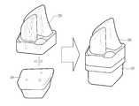
도 3은 본 발명인 금형 인서트 코어를 멜팅함과 동시에 모재와 부착하는 상태를 도시한 도면.
도 4는 본 발명인 반사부재를 도시한 도면.
도 5는 본 발명인 반사부재의 다른 실시예를 도시한 도면.
도 6은 본 발명인 금형 인서트 코어 제조방법을 도시한 블록도.1 is a block diagram showing a method for manufacturing a mold insert core according to the prior art.
Figure 2 is a view of the present invention mold insert core manufacturing apparatus.
3 is a view showing a state in which the present invention is attached to the base material while melting the mold insert core of the present invention.
4 is a view showing a reflecting member of the present invention.
5 is a view showing another embodiment of the reflecting member of the present invention;
Figure 6 is a block diagram showing a method for manufacturing a mold insert core of the present invention.
아래에서는 첨부한 도면을 참조하여 본 발명이 속하는 기술분야에서 통상의 지식을 가진 자가 용이하게 실시할 수 있도록 본 발명의 실시예를 상세히 설명한다. 그러나 본 발명은 여러 가지 상이한 형태로 구현될 수 있으며 여기에서 설명하는 실시예에 한정되지 않는다. 그리고 도면에서 본 발명을 명확하게 설명하기 위해서 설명과 관계없는 부분은 생략하였으며, 명세서 전체를 통하여 유사한 부분에 대해서는 유사한 도면 부호를 붙였다.DETAILED DESCRIPTION Hereinafter, exemplary embodiments of the present invention will be described in detail with reference to the accompanying drawings so that those skilled in the art may easily implement the present invention. The present invention may, however, be embodied in many different forms and should not be construed as limited to the embodiments set forth herein. In the drawings, parts irrelevant to the description are omitted in order to clearly describe the present invention, and like reference numerals designate like parts throughout the specification.
본 발명은 레이저 멜팅 방법을 이용하여 금형 인서트 코어를 제조함으로써 대자인 자유도를 향상시킬 수 있고, 소재의 소착불량을 방지하며, 더불어 냉각수 채널도 동시에 형성시킬 수 있는 기술이다.The present invention is a technology that can improve the degree of freedom of substitution by manufacturing a mold insert core using a laser melting method, to prevent poor adhesion of the material, and also to form a cooling water channel at the same time.
이와 같은 본 발명인 금형 인서트 코어 제조장치는 도 2 및 도 3에 도시된 바와 같이, 모재(10) 배치되는 본체(100)와, 상기 모재(10)의 상면에 금형강(SKD61) 분말을 수분 간격으로 연속하여 도포하는 분말 공급장치(200), 상기 모재(10) 상면에 도포된 금형강(SKD61) 분말에 레이저빔을 조사하여 금형강(SKD61)을 멜팅시켜서 금형 인서트 코어 외형 및 냉각수 채널을 순차적으로 형성시키는 레이저장치(300)를 포함한다.As the mold insert core manufacturing apparatus of the present invention as shown in Figs. 2 and 3, the
한편, 모재(10)는 금형강(SKD61) 분말을 주조로 제조한 다음, 제조된 모재(10)를 단조 또는 압연하여 완성한다.On the other hand, the
상기 본체(100)는 내부에 밀폐된 공간을 가지며, 바닥면에는 본체(100) 외부에서 내부로 슬라이딩 이동하는 LM가이드(110)가 설치되고, 상기 LM 가이드(110) 상면에는 모재(10)를 배치하기 위한 받침대(120)가 설치되며, 일측면에는 본체(100) 내부에 N2 또는 Ar을 주입하기 위한 N2 또는 Ar 주입장치(130)가 설치된다.The
즉, 상기 본체(100)는 모재(10)를 받침대(120) 올려놓고, 본체(100)의 외측에 구비된 버튼(미도시)을 누르면 받침대(120)가 LM 가이드(110)를 따라 본체(100) 내부로 이동하는 한편, 멜팅 가공이 시작되면 상기 N2 또는 Ar 주입장치(130)를 통해 본체(100) 내부로 N2 또는 Ar이 주입되면서 금형강(SKD61) 분말의 산화를 방지한다.That is, the
상기 분말 공급장치(200)는 상기 본체(100) 내부로 이동한 모재(10)의 상면에 금형 인서트 코어(20)를 제조하기 위한 금형강(SKD61) 분말을 수분 또는 수십분 간격으로 얇게 도포하는 것으로, 상기 본체(100)의 일측에 설치되고 금형강(SKD61) 분말이 저장되는 저장탱크(210)와, 상기 저장탱크(210)에 저장된 금형강(SKD61) 분말을 상기 모재(10) 상면에 도포되도록 이동시키는 이동바(220)를 포함하며, 상기 이동바(220)는 후술되는 CPU의 제어에 의해 수분 또는 수십분 간격으로 저장탱크(210)에 저장된 금형강(SKD61) 분말을 모재(10) 상면에 도포되도록 이동시킨다.The
즉, 상기 분말 공급장치(200)는 모재(10) 상면에 얇게 금형강(SKD61) 분말 수분 간격으로 연속하여 도포되게 이동시킴으로써 다단으로 멜팅작업을 수행할 수 있으며, 이에 금형 인서트 코어(20)의 내부 형상 및 외부 형상을 동시에 가공할 수 있다.That is, the
상기 레이저장치(300)는 모재(10) 상면에 얇게 도포된 금형강(SKD61) 분말을 멜팅하여 다단으로 금형 인서트 코어(20)의 내부 형상 및 외부 형상을 동시에 가공하는 것으로, 금형 인서트 코어(20) 외형 및 금형 인서트 코어 내부에 형성되는 냉각수 채널 형상이 저장된 CPU(310)와, 상기 CPU(310)의 제어에 의해 레이저빔을 조사하는 파이버 레이저(320)와, 상기 파이버 레이저(320)의 레이저빔을 전후 좌우로 이동시키는 스캐너(330)와, 상기 파이버 레이저(320)의 레이저빔을 확장시키는 렌즈(340)를 포함한다.The
즉, 레이저장치(300)는 CPU(310)의 제어에 의해 파이버 레이저(320)는 레이저 빔을 조사하게 되는데, 이때 스캐너(330)가 전후좌우로 이동하면서 파이버 레이저(320)에서 조사되는 레이저 빔의 위치를 변경하고, 이에 따라 레이저 빔은 모재(10) 상면에 도포된 금형강(SKD61) 분말 전체를 멜팅하면서 금형 인서트 코어 형상을 가공한다. 이때 파이버 레이저(320)에서 조사되는 레이저 빔은 렌즈(340)를 통과하면서 크게 확장된다.That is, the
한편, 레이저장치(300)는 렌즈(340)와 모재(10) 사이에는 파이버 레이저(320)에서 조사되는 레이저 빔을 경사지게 조사되도록 하는 반사부재(350)(350')를 포함한다.On the other hand, the
상기 반사부재(350)(350')는 도 5 및 도 6에 도시된 바와 같이, 사각틀 또는 원형틀 형태로 이루어지고, 렌즈(340) 하부의 본체(100)에 지지대(140)를 통해 고정되며, 내주면 또는 내주원이 소정 각도로 경사진 경사면 또는 경사원으로 형성된다.As shown in FIGS. 5 and 6, the
즉, 파이버 레이저(320)에서 조사되는 레이저 빔이 반사부재(350)(350')의 경사면 또는 경사원(351)(351')에 조사되면서 굴절되면서 대각선으로 조사되고, 이에 따라 모재(10) 상면에 도포된 금형강(SKD61) 분말의 모서리 부분까지 전달된다.That is, the laser beam irradiated from the
이와 같이 상기 반사부재(350)(350')를 통해 경사지게 형성되는 금형 인서트 코어(20) 외형까지 멜팅이 가능하다.As described above, the mold
이하, 상기와 같은 구성을 가지는 금형 인서트 코어 제조장치를 이용하여 금형 인서트 코어를 가공하는 방법을 설명한다.Hereinafter, the method of processing a mold insert core using the metal mold | die insert core manufacturing apparatus which has the above structures is demonstrated.
본 발명인 금형 인서트 코어 제조방법은 a) 본체(100)의 받침대(120)에 미리 제조된 모재(10)를 올려놓고, LM 가이드(110)를 이용하여 가공위치까지 이동시키는 단계와, b) 저장탱크(210)에 저장된 금형강(SKD61) 분말을 이동바(220)를 이용하여 모재(10) 상면에 얇게 도포하는 단계와, c) 금형 인서트 코어(20) 외형이 저장된 CPU(310)의 제어에 의해 파이버 레이저(320)로부터 레이저빔이 조사되고, 조사된 레이저빔은 스캐너(330)와 렌즈(340)를 통해 모재(10) 상면에 도포된 금형강(SKD61) 분말에 조사되면서 멜팅하는 한편, 모재(10) 상면에 도포된 금형강(SKD61) 분말의 멜팅이 완료되면, 상기 b) 및 상기 c) 단계를 반복하면서 금형 인서트 코어(10) 전체 외형을 형성하도록 멜팅 작업을 수행하는 단계;를 수행한다.Method of manufacturing a mold insert core of the present invention comprises the steps of a) placing a
상기와 같은 본 발명인 금형 인서트 코어 제조방법을 첨부된 도 6을 참조하여 상세히 설명하면 다음과 같다.Referring to Figure 6 attached to the mold insert core manufacturing method of the present invention as described above are as follows.
먼저, 금형강(SKD61) 분말을 주조하여 모재의 외형을 형성하고, 형성된 모재를 단조 또는 압연하여 완성된 모재(10)를 제조한다(S10).First, the mold steel (SKD61) powder is cast to form an outer shape of the base material, and the finished
S10 단계가 완료되면, 완성된 모재(10)를 본체(100)의 받침대(120)에 배치시킨 다음, LM 가이드(110)를 이용하여 본체(100)의 내부로 이동시키고, 저장탱크(210)에 저장된 금형강(SKD61) 분말을 이동바(220)를 이용하여 상기 모재(10) 상면에 얇게 도포한다(S20).When the step S10 is completed, the completed
이때, 상기 이동바(220)는 수분 또는 수십분 마다 저장탱크(210)와 모재(10) 사이를 왕복하면서 저장탱크(210)에 저장된 금형강(SKD61) 분말을 모재(10) 상면에 연속하여 얇게 도포하며, 왕복하는 시간은 CPU(310)에 의해 조절된다.At this time, the moving
S20 단계가 완료되면, CPU(310)에 설정된 금형 인서트 코어(20)의 하단부 수평단면의 형상과 동일하게 모재(10) 상면에 도포된 금형강(SKD61) 분말이 멜팅되도록 파이버 레이저(320)를 작동시켜 레이저빔을 조사시키고, 상기 파이버 레이저(320)에서 조사된 레이저빔은 렌즈(340)를 통해 모재(10) 상면에 도포된 금형강(SKD61) 분말에 조사되면서 멜팅된다(S30).When the step S20 is completed, the
이때, 파이버 레이저(320)에서 조사된 레이저빔은 스캐너(330)에 의해 전후 좌우로 이동하면서 모재(10) 상면에 도포된 금형강(SKD61) 분말 전체를 멜팅하고 형상을 가공한다.At this time, the laser beam irradiated from the
그리고 모재(10) 상면에 도포된 금형강(SKD61) 분말의 모서리 부분은 레이저빔이 반사부재(350)에 의해 반사되면서 조사되어 멜팅된다.And the corner portion of the mold steel (SKD61) powder applied to the upper surface of the
상기와 같이 레이저빔을 통해 모재(10) 상면에 도포된 금형강(SKD61) 분말 전체를 멜팅함으로써 금형 인서트 코어 최하단부 내부 형상 및 외부 형상을 가공한다. 이때 내부 형상은 차후 냉각수 채널을 형상하며, 이에 따라 별도의 냉각수 채널을 가공할 필요가 없고, 냉각수 채널의 자유도와 냉각성을 증대시킬 수 있다.As described above, the inner and outer shapes of the lowermost end of the mold insert core are processed by melting the entire mold steel (SKD61) powder applied to the upper surface of the
상기와 같이 금형 인서트 코어 최하단부 멜팅이 완료되면, 이동바(220)에 의해 금형 인서트 코어 최하단부가 형성된 모재(10) 상면에 다시 금형강(SKD61) 분말을 얇게 도포하고, 레이저장치(300)를 통해 멜팅하여 금형 인서트 코어 최하단부의 위부분을 가공한다.When the melting of the mold insert core bottom end as described above is completed, the mold steel (SKD61) powder is applied thinly to the upper surface of the
이와 같은 방법으로 금형 인서트 코어 외형 전체를 가공하며, 이와 동시에 금형 인서트 코어(20) 멜팅시 모재(10)도 함께 일체화 된다.In this manner, the entire mold insert core external shape is processed, and at the same time, the
이후, 가공된 금형 인서트 코어(20)는 연마하고(S40), 열처리(S50)한 다음, 코팅하여(S60) 완재품으로 완성한다.Thereafter, the processed
본 발명의 범위는 상기 상세한 설명보다는 후술하는 특허청구범위에 의하여 나타내어지며, 특허청구범위의 의미 및 범위 그리고 그 균등 개념으로부터 도출되는 모든 변경 또는 변형된 형태가 본 발명의 범위에 포함되는 것으로 해석되어야 한다.
The scope of the present invention is shown by the following claims rather than the above description, and all changes or modifications derived from the meaning and scope of the claims and their equivalents should be construed as being included in the scope of the present invention. do.
100: 본체
200: 분말 공급장치
300: 레이저장치100: main body
200: powder feeder
300: laser device
Claims (10)
Translated fromKorean상기 모재의 상면에 금형강 분말을 수분 간격으로 연속하여 도포하는 분말 공급장치;
상기 모재 상면에 도포된 금형강 분말에 레이저빔을 조사하여 금형강을 멜팅시키면서 금형 인서트 코어 외형과 내부에 냉각수 채널을 형성시키는 레이저장치를 포함하는 금형 인서트 코어 제조장치.A main body on which the base material is disposed;
A powder supply device for continuously applying mold steel powder to the upper surface of the base material at intervals of several minutes;
And a laser device for forming a coolant channel in the mold insert core shape and the inside of the mold insert core while melting the mold steel by irradiating a laser beam to the mold steel powder coated on the upper surface of the base material.
상기 본체는 모재가 배치되는 받침대와, 상기 받침대를 슬라이딩 이동시키는 LM가이드, 및 금형강 분말이 레이저빔에 의해 멜팅시 산화되는 것을 방지하기 위한 N2 또는 Ar 주입장치를 포함하는 금형 인서트 코어 제조장치.The method according to claim 1,
The main body is a mold insert core manufacturing apparatus including a pedestal, the LM guide for sliding the pedestal base, and the N2 or Ar injection device for preventing the mold steel powder is oxidized during melting by the laser beam.
상기 분말 공급장치는 금형강 분말이 저장되는 저장탱크와, 상기 저장탱크에 저장된 금형강 분말을 상기 모재 상면에 도포되도록 이동시키는 이동바를 포함하는 금형 인서트 코어 제조장치.The method according to claim 1,
The powder supply apparatus includes a storage tank in which the mold steel powder is stored, and a mold bar for moving the mold steel powder stored in the storage tank to be applied to the upper surface of the base material.
상기 레이저 장치는 금형 인서트 코어 외형 및 냉각수 채널 형상이 설정된 CPU와, 상기 CPU의 제어에 의해 레이저빔을 조사하는 파이버 레이저와, 상기 파이버 레이저의 레이저빔을 전후 좌우로 이동시키는 스캐너와, 상기 파이버 레이저의 레이저빔을 확장시키는 렌즈를 포함하는 금형 인서트 코어 제조장치.The method according to claim 1,
The laser device includes a CPU in which a mold insert core shape and a coolant channel shape are set, a fiber laser for irradiating a laser beam under the control of the CPU, a scanner for moving the laser beam of the fiber laser back and forth, and the fiber laser. Mold insert core manufacturing apparatus comprising a lens for expanding the laser beam of the.
상기 레이저 장치와 모재 사이에는 레이저빔을 반사시키는 반사부재를 포함하는 금형 인서트 코어 제조장치.The method according to claim 1,
Mold insert core manufacturing apparatus comprising a reflective member for reflecting a laser beam between the laser device and the base material.
상기 반사부재는 사각틀 또는 원형틀 형태로 이루어지고, 내주면이 경사면 또는 경사원으로 형성되는 금형 인서트 코어 제조장치.The method according to claim 5,
The reflective member is formed in the form of a rectangular frame or a circular frame, the inner peripheral surface of the mold insert core manufacturing apparatus is formed as an inclined surface or inclined circle.
상기 반사부재는 본체 내부에 지지대를 통해 고정되는 금형 인서트 코어 제조장치.The method according to claim 5,
The reflective member is a mold insert core manufacturing apparatus is fixed to the inside of the main body through a support.
a) 본체의 받침대에 모재를 올려 놓고, LM 가이드를 이용하여 가공위치까지 이동시키는 단계;
b) 저장탱크에 저장된 금형강 분말을 이동바를 이용하여 이동시키고, 상기 모재 상면에 얇게 도포하는 단계; 및
c) 금형 인서트 코어 외형이 저장된 CPU의 제어에 의해 파이버 레이저로부터 레이저빔을 조사하고, 조사한 레이저빔은 스캐너와 렌즈를 통해 모재 상면에 도포된 금형강 분말에 조사되면서 멜팅하는 한편, 모재 상면에 도포된 금형강 분말의 멜팅이 완료되면, 상기 b) 및 상기 c) 단계를 반복하면서 금형 인서트 코어 외형이 형성되도록 멜팅 작업을 반복 수행하는 단계;를 포함하는 금형 인서트 코어 제조 방법.As a mold insert core manufacturing method,
a) placing the base material on the base of the main body, and moving to the machining position using the LM guide;
b) moving the mold steel powder stored in the storage tank by using a moving bar and applying a thin layer on the upper surface of the base material; And
c) The laser beam is irradiated from the fiber laser under the control of the CPU in which the mold insert core shape is stored. When the melting of the mold steel powder is completed, repeating the steps b) and c) while repeating the melting operation to form the mold insert core shape; comprising a mold insert core manufacturing method comprising a.
c) 단계에서 파이버 레이저에서 조사되는 레이저 빔은 스캐너에 의해 전후좌우로 위치가 변경되고, 반사부재에 의해 반사되면서 경사지게 조사되는 금형 인서트 코어 제조 방법.The method according to claim 8,
The method of manufacturing a mold insert core in which the laser beam irradiated from the fiber laser in step c) is changed in front, rear, left, and right sides by a scanner and is inclinedly reflected while being reflected by a reflecting member.
c) 단계 후 완성된 금형 인서트 코어는 연마하고, 열처리 한 다음, 코팅하는 단계를 포함하는 금형 인서트 코어 제조 방법.The method according to claim 8,
and c) polishing the finished mold insert core after the step, and then heat-treating and coating the mold insert core.
Priority Applications (1)
| Application Number | Priority Date | Filing Date | Title |
|---|---|---|---|
| KR1020100124519AKR20120063385A (en) | 2010-12-07 | 2010-12-07 | Making device and method of slide core |
Applications Claiming Priority (1)
| Application Number | Priority Date | Filing Date | Title |
|---|---|---|---|
| KR1020100124519AKR20120063385A (en) | 2010-12-07 | 2010-12-07 | Making device and method of slide core |
Publications (1)
| Publication Number | Publication Date |
|---|---|
| KR20120063385Atrue KR20120063385A (en) | 2012-06-15 |
Family
ID=46683898
Family Applications (1)
| Application Number | Title | Priority Date | Filing Date |
|---|---|---|---|
| KR1020100124519ACeasedKR20120063385A (en) | 2010-12-07 | 2010-12-07 | Making device and method of slide core |
Country Status (1)
| Country | Link |
|---|---|
| KR (1) | KR20120063385A (en) |
Cited By (3)
| Publication number | Priority date | Publication date | Assignee | Title |
|---|---|---|---|---|
| EP3508288A1 (en)* | 2018-01-08 | 2019-07-10 | United Technologies Corporation | Hybrid additive manufacturing |
| CN111347171A (en)* | 2018-12-20 | 2020-06-30 | 财团法人金属工业研究发展中心 | Combined type laser processing device |
| CN112453704A (en)* | 2020-11-25 | 2021-03-09 | 南京航空航天大学 | Large-thickness titanium alloy narrow-gap laser welding device and method based on automatic powder laying |
- 2010
- 2010-12-07KRKR1020100124519Apatent/KR20120063385A/ennot_activeCeased
Cited By (4)
| Publication number | Priority date | Publication date | Assignee | Title |
|---|---|---|---|---|
| EP3508288A1 (en)* | 2018-01-08 | 2019-07-10 | United Technologies Corporation | Hybrid additive manufacturing |
| US20190210113A1 (en)* | 2018-01-08 | 2019-07-11 | United Technologies Corporation | Hybrid additive manufacturing |
| CN111347171A (en)* | 2018-12-20 | 2020-06-30 | 财团法人金属工业研究发展中心 | Combined type laser processing device |
| CN112453704A (en)* | 2020-11-25 | 2021-03-09 | 南京航空航天大学 | Large-thickness titanium alloy narrow-gap laser welding device and method based on automatic powder laying |
Similar Documents
| Publication | Publication Date | Title |
|---|---|---|
| US11534861B2 (en) | Laser cutting | |
| JP6443698B2 (en) | Manufacturing method of three-dimensional shaped object | |
| CN203509463U (en) | Composite manufacturing device with conformal cooling channel injection mold | |
| KR101648442B1 (en) | Method of manufacturing three-dimensional sculpture | |
| CN104190931A (en) | Method and device for manufacturing efficient and high-precision composite additive | |
| CN109926584A (en) | A kind of increasing material manufacturing and surface polishing synchronous processing method and device | |
| CN102328081A (en) | Method for rapidly forming three-dimensional metal parts by high-power lasers | |
| US10821663B2 (en) | Method for manufacturing three-dimensional shaped object | |
| KR20180021186A (en) | Method for manufacturing three dimensional shaped sculpture | |
| CN109848566A (en) | A method and device for hybrid laser grinding and polishing parts and molds | |
| KR20120063385A (en) | Making device and method of slide core | |
| KR20200006277A (en) | Mold having conformal cooling channel by using 3D printer and method therefor | |
| JP2015174146A (en) | Method for producing component | |
| TW202106414A (en) | Manufacturing method for three-dimensional molded object, lamination molding apparatus, and three-dimensional molded | |
| JP6857861B2 (en) | Manufacturing method of three-dimensional shaped object | |
| JP2012224907A (en) | Method for manufacturing three-dimensionally shaped article | |
| JP6146294B2 (en) | Manufacturing method of three-dimensional shaped object | |
| JP7067134B2 (en) | Modeling method of laminated modeling device and laminated modeling device | |
| CN107617859A (en) | A kind of Digit Control Machine Tool aftertreatment technology based on SLS3D print dies | |
| JP6731642B2 (en) | Method for manufacturing three-dimensional shaped object | |
| JP6229411B2 (en) | Laser processing apparatus and laser processing method | |
| US20200198061A1 (en) | Method of manufacturing fine wire | |
| WO2019151540A1 (en) | Method for manufacturing three-dimensional molded object | |
| JP7325698B1 (en) | Additive manufacturing equipment | |
| KR101405446B1 (en) | A manufacturing method of buckle for belt |
Legal Events
| Date | Code | Title | Description |
|---|---|---|---|
| A201 | Request for examination | ||
| PA0109 | Patent application | Patent event code:PA01091R01D Comment text:Patent Application Patent event date:20101207 | |
| PA0201 | Request for examination | ||
| PG1501 | Laying open of application | ||
| E902 | Notification of reason for refusal | ||
| PE0902 | Notice of grounds for rejection | Comment text:Notification of reason for refusal Patent event date:20120717 Patent event code:PE09021S01D | |
| E601 | Decision to refuse application | ||
| PE0601 | Decision on rejection of patent | Patent event date:20121203 Comment text:Decision to Refuse Application Patent event code:PE06012S01D Patent event date:20120717 Comment text:Notification of reason for refusal Patent event code:PE06011S01I |