KR20120062792A - Inductively chargeable power pack - Google Patents
Inductively chargeable power packDownload PDFInfo
- Publication number
- KR20120062792A KR20120062792AKR1020127006999AKR20127006999AKR20120062792AKR 20120062792 AKR20120062792 AKR 20120062792AKR 1020127006999 AKR1020127006999 AKR 1020127006999AKR 20127006999 AKR20127006999 AKR 20127006999AKR 20120062792 AKR20120062792 AKR 20120062792A
- Authority
- KR
- South Korea
- Prior art keywords
- charging device
- power pack
- charging
- power
- current
- Prior art date
- Legal status (The legal status is an assumption and is not a legal conclusion. Google has not performed a legal analysis and makes no representation as to the accuracy of the status listed.)
- Ceased
Links
Images


Classifications
- H—ELECTRICITY
- H02—GENERATION; CONVERSION OR DISTRIBUTION OF ELECTRIC POWER
- H02J—CIRCUIT ARRANGEMENTS OR SYSTEMS FOR SUPPLYING OR DISTRIBUTING ELECTRIC POWER; SYSTEMS FOR STORING ELECTRIC ENERGY
- H02J50/00—Circuit arrangements or systems for wireless supply or distribution of electric power
- H02J50/005—Mechanical details of housing or structure aiming to accommodate the power transfer means, e.g. mechanical integration of coils, antennas or transducers into emitting or receiving devices
- H—ELECTRICITY
- H01—ELECTRIC ELEMENTS
- H01M—PROCESSES OR MEANS, e.g. BATTERIES, FOR THE DIRECT CONVERSION OF CHEMICAL ENERGY INTO ELECTRICAL ENERGY
- H01M10/00—Secondary cells; Manufacture thereof
- H01M10/42—Methods or arrangements for servicing or maintenance of secondary cells or secondary half-cells
- H01M10/46—Accumulators structurally combined with charging apparatus
- H—ELECTRICITY
- H02—GENERATION; CONVERSION OR DISTRIBUTION OF ELECTRIC POWER
- H02J—CIRCUIT ARRANGEMENTS OR SYSTEMS FOR SUPPLYING OR DISTRIBUTING ELECTRIC POWER; SYSTEMS FOR STORING ELECTRIC ENERGY
- H02J50/00—Circuit arrangements or systems for wireless supply or distribution of electric power
- H02J50/10—Circuit arrangements or systems for wireless supply or distribution of electric power using inductive coupling
- H02J50/12—Circuit arrangements or systems for wireless supply or distribution of electric power using inductive coupling of the resonant type
- H—ELECTRICITY
- H02—GENERATION; CONVERSION OR DISTRIBUTION OF ELECTRIC POWER
- H02J—CIRCUIT ARRANGEMENTS OR SYSTEMS FOR SUPPLYING OR DISTRIBUTING ELECTRIC POWER; SYSTEMS FOR STORING ELECTRIC ENERGY
- H02J50/00—Circuit arrangements or systems for wireless supply or distribution of electric power
- H02J50/70—Circuit arrangements or systems for wireless supply or distribution of electric power involving the reduction of electric, magnetic or electromagnetic leakage fields
- H—ELECTRICITY
- H02—GENERATION; CONVERSION OR DISTRIBUTION OF ELECTRIC POWER
- H02J—CIRCUIT ARRANGEMENTS OR SYSTEMS FOR SUPPLYING OR DISTRIBUTING ELECTRIC POWER; SYSTEMS FOR STORING ELECTRIC ENERGY
- H02J50/00—Circuit arrangements or systems for wireless supply or distribution of electric power
- H02J50/80—Circuit arrangements or systems for wireless supply or distribution of electric power involving the exchange of data, concerning supply or distribution of electric power, between transmitting devices and receiving devices
- H—ELECTRICITY
- H02—GENERATION; CONVERSION OR DISTRIBUTION OF ELECTRIC POWER
- H02J—CIRCUIT ARRANGEMENTS OR SYSTEMS FOR SUPPLYING OR DISTRIBUTING ELECTRIC POWER; SYSTEMS FOR STORING ELECTRIC ENERGY
- H02J7/00—Circuit arrangements for charging or depolarising batteries or for supplying loads from batteries
- H02J7/0047—Circuit arrangements for charging or depolarising batteries or for supplying loads from batteries with monitoring or indicating devices or circuits
- H—ELECTRICITY
- H02—GENERATION; CONVERSION OR DISTRIBUTION OF ELECTRIC POWER
- H02J—CIRCUIT ARRANGEMENTS OR SYSTEMS FOR SUPPLYING OR DISTRIBUTING ELECTRIC POWER; SYSTEMS FOR STORING ELECTRIC ENERGY
- H02J7/00—Circuit arrangements for charging or depolarising batteries or for supplying loads from batteries
- H02J7/007—Regulation of charging or discharging current or voltage
- H02J7/007188—Regulation of charging or discharging current or voltage the charge cycle being controlled or terminated in response to non-electric parameters
- H02J7/007192—Regulation of charging or discharging current or voltage the charge cycle being controlled or terminated in response to non-electric parameters in response to temperature
- H02J7/007194—Regulation of charging or discharging current or voltage the charge cycle being controlled or terminated in response to non-electric parameters in response to temperature of the battery
- H—ELECTRICITY
- H01—ELECTRIC ELEMENTS
- H01M—PROCESSES OR MEANS, e.g. BATTERIES, FOR THE DIRECT CONVERSION OF CHEMICAL ENERGY INTO ELECTRICAL ENERGY
- H01M10/00—Secondary cells; Manufacture thereof
- H01M10/42—Methods or arrangements for servicing or maintenance of secondary cells or secondary half-cells
- H01M10/48—Accumulators combined with arrangements for measuring, testing or indicating the condition of cells, e.g. the level or density of the electrolyte
- H01M10/486—Accumulators combined with arrangements for measuring, testing or indicating the condition of cells, e.g. the level or density of the electrolyte for measuring temperature
- Y—GENERAL TAGGING OF NEW TECHNOLOGICAL DEVELOPMENTS; GENERAL TAGGING OF CROSS-SECTIONAL TECHNOLOGIES SPANNING OVER SEVERAL SECTIONS OF THE IPC; TECHNICAL SUBJECTS COVERED BY FORMER USPC CROSS-REFERENCE ART COLLECTIONS [XRACs] AND DIGESTS
- Y02—TECHNOLOGIES OR APPLICATIONS FOR MITIGATION OR ADAPTATION AGAINST CLIMATE CHANGE
- Y02E—REDUCTION OF GREENHOUSE GAS [GHG] EMISSIONS, RELATED TO ENERGY GENERATION, TRANSMISSION OR DISTRIBUTION
- Y02E60/00—Enabling technologies; Technologies with a potential or indirect contribution to GHG emissions mitigation
- Y02E60/10—Energy storage using batteries
Landscapes
- Engineering & Computer Science (AREA)
- Power Engineering (AREA)
- Computer Networks & Wireless Communication (AREA)
- General Chemical & Material Sciences (AREA)
- Manufacturing & Machinery (AREA)
- Chemical & Material Sciences (AREA)
- Chemical Kinetics & Catalysis (AREA)
- Electrochemistry (AREA)
- Electromagnetism (AREA)
- Physics & Mathematics (AREA)
- Charge And Discharge Circuits For Batteries Or The Like (AREA)
- Battery Mounting, Suspending (AREA)
- Secondary Cells (AREA)
Abstract
Translated fromKoreanDescription
Translated fromKorean본 발명은 전기기기에 관한 것으로, 구체적으로는 휴대기기의 파워팩의 유도 충전장치에 관한 것이다.The present invention relates to an electric device, and more particularly, to an inductive charging device for a power pack of a portable device.
파워팩이란 휴대폰, PDA, 미디어 플레이어 등의 휴대기기에 전력을 공급하는데 사용되는 것이다. 대개의 파워팩은 충전식 전기화학전지나 배터리를 구비하고, 이들은 배전망이나 자동차 배터리와 같은 전원에서 전력을 끌어오는 전용 충전기를 이용해 충전되는 외부나 내부 장치이다.Power packs are used to power mobile devices such as cell phones, PDAs and media players. Most power packs have rechargeable electrochemical cells or batteries, which are external or internal devices that are charged using a dedicated charger that draws power from a power source such as a distribution network or car battery.
배전망이나 전선을 통해 전력을 받는 충전기는 큰 플러그 박스로이루어지고, 그안에 변압기와 정류기가 들어있으며, 배전망의 소켓에 연결되는 핀이 달려있다. 사용중에 플러그 박스가 소켓에 끼워지고, 연결플러그를 통해 전선이 전기기기에 연결된다. 전선이 당겨지면, 커넥터가 파손되거나 전기기기가 땅에 떨어질 수 있다. 또, 이런 전선은 하나의 소켓에서 여러 기기들을 충전할 때는 여러가닥이 되어 보기에 좋지 않고 불편할 뿐만아니라 서로 꼬이기도 한다.Chargers powered by power grids or wires are made up of large plug boxes, containing transformers and rectifiers, with pins connected to the sockets of the grid. During use, the plug box is inserted into the socket, and the wire is connected to the electrical device through the connecting plug. If the wire is pulled, the connector may break or the electrical equipment may fall to the ground. In addition, these wires are not only uncomfortable and uncomfortable, but also twisted together when charging multiple devices in one socket.
휴대용 전기기기에 끼울 수 있는 각종 유도 전력 리시버에 관련된 시스템들이 많다. 이런 리시버들은 전기기기의 파워팩에 끼울 수 있다. 이런 시스템에서, 유도기기는 외부기기로서 접점을 통해 파워팩에 연결된다.Many systems involve inductive power receivers that can be plugged into portable electrical equipment. These receivers can be plugged into the power pack of an electrical device. In such a system, the induction equipment is connected to the power pack via contacts as external equipment.
PCT/KR2007/004418에 소개된 시스템은 "Non-contact charger system of wireless power transmission for battery and control method thereof"란 명칭을 갖는 특허출원으로서, 배터리팩의 하우징 안에 수신기를 설치한 무선 충전시스템에 관한 것이다. 이 리시버에는 다수의 별도의 전자블록들이 있고, 그 안에 2차 코어블록, 2차 정류블록, 배터리 충전블록, 충전 감시블록 및 배터리 보호블록이 있고, 각각이 별도의 충전과정을 제어한다. 모든 각각의 회로블록이 배터리팩 하우징 안에 설치되므로, 이들 블록은 모두 전기화학전지와 가용공간을 공유한다. 따라서, 유도충전을 위한 제어회로 공간을 확보하려면 배터리의 크기와 그 용량을 줄일 수 밖에 없다.The system introduced in PCT / KR2007 / 004418 is a patent application entitled "Non-contact charger system of wireless power transmission for battery and control method," which relates to a wireless charging system having a receiver installed in a housing of a battery pack. . The receiver has a number of separate electronic blocks, in which there are a secondary core block, a secondary rectification block, a battery charging block, a charging supervisory block and a battery protection block, each of which controls a separate charging process. Since each individual circuit block is installed in the battery pack housing, these blocks all share the available space with the electrochemical cell. Therefore, in order to secure a control circuit space for inductive charging, it is inevitable to reduce the size and capacity of the battery.
본 발명은 종래의 이와같은 문제점을 감안하여 안출된 것으로, 회로블록을 최소로 하고 전체 크기를 더 작게 하여 배터리팩의 하우징 안에 유도 수신기를 설치하는 것을 목적으로 한다.SUMMARY OF THE INVENTION The present invention has been made in view of such a conventional problem, and aims to install an induction receiver in a housing of a battery pack with a minimum circuit block and a smaller overall size.
파워팩은 신뢰성이 아주 높은 스마트하고 보호성이 좋은 전자장치로서, 열과 과전류와 과전압 상태에 아주 민감하다. 충전 프로토콜을 따라 파워팩을 충전할 때 주의를 해야하는데, 이때의 프로토콜은 일반적으로 충전식 전기화학전지의 화학적 성질에 의해 규정된다. 전력전달을 제어하고, DC 전류/전압을 생성하며, 배터리팩을 감시보호하고, 휴대통신기와 통신하는 복잡한 전자회로가 필요하다.Powerpacks are highly reliable, smart and protective electronics that are very sensitive to heat, overcurrent and overvoltage conditions. Care must be taken when charging the power pack following the charging protocol, which is generally defined by the chemistry of the rechargeable electrochemical cell. There is a need for complex electronic circuits that control power delivery, generate DC current / voltage, monitor and protect battery packs, and communicate with mobile communications.
본 발명의 실시예들은 파워팩의 유도 충전은 물론 유도식 파워팩을 위한 간단하고, 스마트하며, 저렴하고 얇은 전자장치를 제공한다. 본 발명의 장치는 이상의 모든 원리들을 구현하고, 다수의 집적회로(IC)나 하나의 ASIC(Application Specific Integrated Circuit)에 의해 구현된다.Embodiments of the present invention provide a simple, smart, inexpensive and thin electronic device for inductive charging of a power pack as well as an inductive power pack. The device of the present invention implements all of the above principles and is implemented by multiple integrated circuits (ICs) or one application specific integrated circuit (ASIC).
따라서, 본 발명은 파워팩에 전력을 공급하는 충전장치를 제공하는데, 이 충전장치는 1차인덕터와 유도결합하는 2차인덕터; 파워팩으로의 전력의 전달을 제어하는 ASIC; 및 파워팩이 유도충전되고 있음을 표시하고, 전자스위치를 통해 전자요소에 연결된 데이터 접점;을 포함한다. 상기 ASIC는 유도 파워아울렛과의 통신을 관리한다. 본 발명의 충전장치는 교류 전원으로부터 정류된 직류전력을 공급하는 정류기를 더 포함할 수 있다.Accordingly, the present invention provides a charging device for supplying power to a power pack, the charging device comprising a secondary inductor coupled to the primary inductor; An ASIC that controls the transfer of power to the power pack; And a data contact indicating that the power pack is inductively charged and connected to the electronic element through an electronic switch. The ASIC manages communication with induction power outlets. The charging device of the present invention may further include a rectifier for supplying the DC power rectified from the AC power source.
본 발명의 충전장치는 전기화학전지 반대쪽으로 자속을 안내하는 자기차폐판을 더 포함할 수 있다. 또, 이런 충전장치는 파워팩에 설치될 수 있다. 또, 본 발명의 충전장치가 배터리의 온도를 측정하는 온도센서를 더 포함할 수 있다. 본 발명에 의하면, 감시된 배터리 온도가 -10~45 ℃일 때 파워팩을 충전하도록 하면 좋다.The charging device of the present invention may further include a magnetic shield plate for guiding the magnetic flux toward the opposite side of the electrochemical cell. In addition, such a charging device may be installed in a power pack. In addition, the charging device of the present invention may further include a temperature sensor for measuring the temperature of the battery. According to the present invention, the power pack may be charged when the monitored battery temperature is -10 to 45 ° C.
본 발명에 의하면, ASIC가 충전전류, 방전전류, 실제 배터리충전, 배터리 전압, 파워팩의 온도 및 배터리 온도로 이루어지는 군에서 선택된 적어도 하나의 변수를 감시할 수 있다. 또, 이런 ASIC가 과잉 충전전류, 낮은 충전전류, 과잉 온도, 무부하, 외부 충전기의 무존재, 배터리 충전중 및 완전충전 파워팩으로 이루어진 군에서 선택된 상태들 중의 적어도 하나에 응답해 충전전류를 방전하는 보호회로를 더 포함할 수 있다. 본 발명에 의하면, 이런 ASIC가 충전전류의 연결을 끊기위한 적어도 하나의 전자스위치를 더 포함할 수 있다.According to the present invention, the ASIC can monitor at least one variable selected from the group consisting of charge current, discharge current, actual battery charge, battery voltage, power pack temperature, and battery temperature. In addition, the ASIC discharges the charging current in response to at least one of the following conditions: a group consisting of overcharge current, low charge current, excess temperature, no load, no external charger, during battery charging, and a fully charged power pack. The circuit may further include. According to the present invention, the ASIC may further include at least one electronic switch for disconnecting the charging current.
본 발명에 의하면, ASIC는 충전전류가 상한 임계값보다 높을 때 충전전류의 연결을 끊기위한 적어도 하나의 전자스위치를 더 포함할 수 있는데, 이때의 임계값은 1.1 암페어보다 큰 것이 좋다. 또, ASIC가 충전전류가 하한 임계값보다 낮을 때 충전전류의 연결을 끊기위한 적어도 하나의 전자스위치를 더 포함할 수 있다.According to the present invention, the ASIC may further include at least one electronic switch for disconnecting the charging current when the charging current is higher than the upper limit threshold, wherein the threshold is preferably greater than 1.1 amps. In addition, the ASIC may further include at least one electronic switch for disconnecting the charging current when the charging current is lower than the lower limit threshold.
본 발명의 충전장치는 적어도 하나의 고장 표시기를 더 포함할 수 있다. 또, 본 발명의 충전장치는 과잉 충전전류, 낮은 충전전류, 과잉 온도, 무부하, 외부 충전기의 무존재, 배터리 충전중 및 완전충전 파워팩으로 이루어진 군에서 선택된 적어도 하나의 상태를 표시하는 적어도 하나의 LED를 더 포함할 수도 있다.The charging device of the present invention may further include at least one failure indicator. In addition, the charging device of the present invention is at least one LED that displays at least one state selected from the group consisting of excessive charging current, low charging current, excessive temperature, no load, the absence of an external charger, during battery charging and fully charged power pack It may further include.
본 발명의 충전장치는 호스트 장치와 연결되어 파워팩과 호스트 장치 사이에 통신채널을 제공하는 적어도 하나의 데이터 접점을 더 포함할 수 있다. 본 발명의 충전장치에 속하는 전자요소는 가변저항을 갖는 것이 바람직하다. 또, 전자스위치는 파워팩의 캐소드와 아노드 사이에 연결되는 것이 바람직하다.The charging device of the present invention may further include at least one data contact connected to the host device to provide a communication channel between the power pack and the host device. The electronic element belonging to the charging device of the present invention preferably has a variable resistance. In addition, the electronic switch is preferably connected between the cathode and the anode of the power pack.
본 발명은 또한, 2차인덕터를 제공하는 단계; ASIC를 제공하는 단계; 전자스위치를 통해 전자요소에 연결되는 데이터 접점을 제공하는 단계; 유도 파워아울렛의 1차인덕터에 상기 2차인덕터를 유도결합하는 단계; 및 상기 전자요소를 이용해, 파워팩이 유도충전중임을 표시하는 단계;를 포함하는 파워팩에 전력을 공급하는 방법도 제공한다. 이 방법은 출력 디스플레이를 통해 충전중임을 표시하는 단계를 더 포함할 수 있다.The present invention also provides a method of providing a secondary inductor; Providing an ASIC; Providing a data contact connected to the electronic element via an electronic switch; Inductively coupling the secondary inductor to a primary inductor of an induction power outlet; And using the electronic element, indicating that the power pack is inductively charging. The method may further include indicating that charging is via the output display.
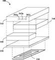
도 1은 본 발명에 따른 유도형 파워팩의 일례의 분리사시도이다.
도 2a는 유도 파워아울렛과 유도충전형 파워팩을 갖춘 유도충전 시스템의 주요소들을 보여주는 블록도이다.
도 2b는 듀얼모드 파워팩을 나타낸 블록도이다.
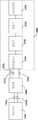
도 3a는 전자기기의 파워팩이 유도기에 연결된 관계를 보여주는 블록도이다.
도 3b~c는 본 발명의 일례의 유도식 파워팩의 예를 보여주는 사시도들이다.
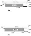
도 4a~b는 2가지 유도식 파워팩의 구성을 보여주는 단면도들이다.
도 5는 유도식 파워팩의 또다른 블록도로서, 보호회로를 사용해 시스템을 보호하는 것을 보여준다.1 is an exploded perspective view of an example of an inductive power pack according to the present invention.
Figure 2a is a block diagram showing the major elements of the inductive charging system with an induction power outlet and inductive charging power pack.
2B is a block diagram illustrating a dual mode power pack.
3A is a block diagram showing a relationship between a power pack of an electronic device and an inductor.
3b to c are perspective views showing an example of an induction power pack of an example of the present invention.
4A to 4B are cross-sectional views illustrating the configuration of two inductive power packs.
5 is another block diagram of an inductive power pack, showing that a protection circuit is used to protect the system.
도 1은 본 발명에 따른 유도형 파워팩(300)의 일례의 분리사시도이다. 이 파우팩(300)은 2차인덕터(320)가 들어있는 케이싱(310), 자속가이드(330), 전기화학전지(340) 및 인터페이스 모듈(100)을 포함한다. 일반적으로, 파어팩(300)은 다수의 전기접점(302a~c)을 통해 전기기기(400)에 연결된다(도 2a 참조).1 is an exploded perspective view of an example of an
케이싱(310)의 크기와 전기화학전지(340)의 특성은 전화기, 미디어 플레이어, 게임기, PDA 등 각종 전기기기에 맞게 선택할 수 있다. 파워팩은 기존의 전기기기를 개조하지 않고도 유도충전 기능을 제공할 수 있는 것이다.The size of the
전기화학전지의 수명이 이 전지로부터 전력을 공급받는 전기기기의 수명보다 짧을 수 있기 때문에, 대부분의 전기기기는 파워팩을 쉽게 교체할 수 있도록 설계된다. 파워팩은 관련 전기기기를 작동시키는데 필요한 전압으로 전력을 공급하는 리튬이온 전지 등의 배터리를 사용하기 때문에 교체가 용이하다. 케이싱(310)의 크기가 전기기기와 일치하면, 유도전력공급을 위해 파워팩(300)을 전기기기에 쉽게 재설치할 수 있다. 케이싱(310) 안에 다른 부품들을 넣으려면, 소형의 전기화학전지(340)를 선택해야 한다. 효과적으로 에너지를 공급할 수 있는 전기화학전지의 예로는 염화치오닐-리튬 전지, 에너지밀도가 높은 Li/SOCL2 전지, Li/SO2 전지, Li/MnO2 전지, 리튬-고분자 전지, 특수전지, 휴대폰 전지, 충전식 리튬이온전지, MiMH 전지, NiCd 전지 등이 있다.Since the life of an electrochemical cell can be shorter than the life of an electrical device powered by the cell, most electrical devices are designed to easily replace the power pack. Power packs are easy to replace because they use batteries, such as lithium-ion batteries, that supply power to the voltage needed to operate the associated electrical equipment. If the size of the
파워팩(300)의 2차인덕터(320)는 대개 1차인덕터(220)와 유도결합하는 유도코일이다(도 2a 참조). 자속가이드(330)는 1차인덕터(220)의 자속을 2차인덕터(320)로 안내하고 주변으로의 자속누설을 줄이기 위한 것이다.The
얇은 자속가이드(330)는 예컨대 비정질 강자성체로 이루어지고 두께는 수 미크론 정도이다. 이런 자속가이드(330)는 전기화학전지(340)는 물론 전기기기를 도체내의 와전류로부터 차단하는 기능을 한다. 경우에 따라서는 두께 20 미크론 정도의 강자성체를 자속가이드로 사용할 수도 있는데, 이 자속가이드의 양쪽면에 고분자층을 적층하면 전ㄴ체 두께가 60미크론 정도로 된다. 비정질 강자성체로 자속가이드를 제작하는 방법은 여러가지가 있지만, 그중에서도, 프린팅, 스탬핑, 커팅, 비정질 강자성 마이크로와이어 클로스(microwire cloth) 등이 있다.The thin
도 2a는 유도 파워아울렛(200)과 유도충전형 파워팩(300)을 갖춘 유도충전 시스템의 주요소들을 보여주는 블록도이다.Figure 2a is a block diagram showing the major elements of the inductive charging system having an
유도 파워아울렛(200)은 드라이버(230)를 통해 자동차 매터리나 송전선과 같은 전원(240)에 유선연결되는 1차인덕터(220)를 포함한다. 드라이버(230)는 1차인덕터(220)에 진동 구동전압을 공급한다. 후술하는 바와 같이, 진동 구동전압의 주파수는 유도결합 시스템의 공진주파수와는 다르도록 선택된다.The
파워팩(300)은 전기부하(400)에 전력을 공급하고, 2차인덕터(320)와 전기화학전지(340)와 인터페이스(100)를 구비한다. 경우에 따라, 2차인덕터(320)와 이터페이스(100)가 전기화학전지의 충전 없이 직접 전기부하(400)에 전력을 추가로 공급할 수도 있다.The
인터페이스(100)는 파워팩(300)을 충전하거나 전기부하(400)으로의 전력 전달을 조절하고, 파워팩(300)과 유도전력 아울렛(200) 사이의 통신을 관리한다. 즉, 인터페이스(100)는 아래와 같은 다양한 기능들을 실행하는데, 물론 아래 기능에 한정되지도 않는다:The
- 2차인덕터(320)에서 생긴 교류전류(AC)를 전기화학전지(340) 충전용의 직류전류(DC)로 정류;Rectifying an alternating current (AC) generated in the
- 전기화학전지(340)의 충전전압 조절;Adjusting the charging voltage of the
- 전기화학전지(340)의 충전전류 조절;Controlling the charging current of the
- 충전전류를 조절하는 등의 방식으로 전기화학전지(340)의 온도 조절;Temperature control of the
- 1차인덕터로 피드백 신호 전송;-Send feedback signal to the primary inductor;
- 유도전력 시스템(200)으로부터의 에너지전달 조절;Regulation of energy transfer from the
- 유도전력 시스템(200)용의 파워팩(300) 확인;Identification of the
- 충전표시등을 통해 파워팩(300)의 충전상태 표시;Displaying the state of charge of the
- 충전과정 자동종료;-Automatic termination of the charging process;
- 전기화학전지(340)와 전기부하(400) 사이의 연결 자동종료;Automatic termination of the connection between the
- 충전상태 감시;-Monitoring of charge status;
- 파워팩의 전압 감시;-Voltage monitoring of the power pack;
- 고장 감지;-Fault detection;
- 전기화학전지의 심방전(deep discharge) 방지;Deep discharge prevention of electrochemical cells;
- 배터리팩 전자소자들과의 동기화/통신.-Synchronization / communication with battery pack electronic devices.
과충전은 많은 전기화학전지에 손상을 줄 수 있음을 알아야 한다. 따라서, 전기화학전지(340)의 충전은 표적전압에 도달하거나 충전전류가 일정치 이상 강하했을 때 자동으로 종료되도록 한다. 또, 과충전 방지를 위해, 하한값에 도달했을 때 전기부하(400)와 전기화학전지의 연결을 끊는 회로차단기를 이용할 수 있다.It should be noted that overcharging can damage many electrochemical cells. Accordingly, the charging of the
과도한 전류는 전기화학전지(340)를 해치고 단락이나 고장을 유발할 수 있기 때문에, 인터페이스(100)가 충방전을 감시한다. 이터페이스(100)는 정격전류, 예컨대 12암페어 정도 이상의 과잉 전류를 삭감하기 위한 전류제한기 역할도 하는데, 이런 과잉 전류가 있으면 배터리가 손상될 수 있다. 전류 감시와 제한 기능은 전류감지 저항기에 의해 제공될 수도 있다. 충전이 끝나면 보호회로가 전기화학전지의 연결을 끊도록 한 경우, 인터페이스는 충전전류에 주기적으로 반응하여 전기화학전지가 완전히 충전되도록 할 수도 있다. 어떤 경우, 충전전류가 끊어지면, 인터페이스(100)가 파워팩(300)의 2차인덕터(320)에 결합된 1차인덕터(220)의 작동을 정지시키는 신호를 보낼 수 있다. 필요하다면, 주기적인 충전과정을 2시간 정도의 일정 강격으로 되풀이할 수도 있다.Since excessive current can damage the
충전과정이 온도에 좌우될 수도 있다. 높은 충전온도는 전기화학전지를 해치고, 낮은 온도는 충전을 제한할 수 있다. 이런 온도 의존성 때문에, 인터페이스(100)는 충전중의 파워팩 온도를 감시하고 조절한다. 한편, 서미스터, 서모커플, 디지탈 센서와 같은 온도센서를 이용해 충전온도를 감시하고, 일정 범위내의 온도를 유지하도록 충전전류를 제한할 수 있다. 또, 경우에 따라서는 -10~45 ℃의 온도범위에서 온도센서가 동작하도록 할 수도 있다.The charging process may depend on temperature. Higher charging temperatures can damage electrochemical cells, and lower temperatures can limit charging. Because of this temperature dependency,
전기화학전지의 사용에 관한 이력 데이터가 예컨대 개스게이즈를 이용해 감시되고 기록될 수 있다. 파워팩의 충전요소를 결정하는데는 충전데이터를 이용한다. 본 발명의 특징은, 파워팩에 유도충전회로가 있어서, 특정 파워팩에 관한 충전데이터를 축적하여 충전과정의 효율을 더 높이는데 사용할 수 있다는 것이다.Historical data relating to the use of electrochemical cells can be monitored and recorded using, for example, gas gauges. The charging data is used to determine the charging element of the power pack. A feature of the present invention is that the power pack has an inductive charging circuit, which can be used to accumulate charging data relating to a specific power pack to further increase the efficiency of the charging process.
도 2a에서 설명한 싱글모드의 경우, 유도형 파워팩(300)은 유도결합으로 전류를 받기만 한다. 도 2b는 듀얼모드 파워팩(300')을 나타낸 블록도로서, 필요시 유선연결된 충전기(202)로부터 전력을 받기도 한다. 듀얼모드 유도형 파워팩(300')은 전용 어댑터가 달린 전기기기에 사용하는데 유리하다.In the single mode described with reference to FIG. 2A, the
듀얼모드 파워팩(300')은 충전선택기(102)를 구비하는데, 이 선택기는 유선연결 충전모드와 유도식 충전모드 사이를 스위칭한다. 충전선택기(102)는 한쪽 충전형이 작용될 때 나머지 충전형의 연결을 끊을 수도 있다. 예를 들어, 유선충전기(202)가 연결되어있으면, 이중충전을 방지하기 위해 2차인덕터(320)의 연결을 끊는다. 한편, 유도충전기(200)가 파워팩(300')에 연결되면 충전선택기(102)가 유선연결 충전커넥터(204)의 연결을 끊을 수 있다. 또는, 충전선택기(102)가 유도식-유선식 충전모드들을 조합하여 동시 충전을 제어할 수도 있다.The dual mode power pack 300 'includes a
도 3a는 전자기기(1400)의 파워팩(1300)이 유도기(1000)에 연결된 관계를 보여주는 블록도이다. 유도기(100)는 2차인덕터(1320), 이터페이스(1100), 배터리충전기(1110) 및 정류기(1120)를 포함한다. 인터페이스(1000)는 2개 이상의 전력전달 접점(1302a~b)와 하나 이상의 데이터전달 접점(1304)을 통해 파워팩(1300)에 연결된다.3A is a block diagram illustrating a relationship in which the
유도기(1000)는 파워팩(1300)이 유도전력을 받도록 하기위한 것이다. 유도기(100)는 휴대폰과 같은 기기(1400)의 케이싱 안에 설치되는 크기를 갖는다.The
데이터전달 접점(1304)은 파워팩(1300)과 전기기기(1400) 사이에 통신채널을 제공한다. 이 통신채널은 파워팩에 관한 정보, 예컨대 전하레벨이나 충전중의 온도와 같은 정보를 암호화하는 데이터신호를 전달하는데 사용된다. 따라서, 제1 데이터전달 접점(1304)는 전지의 온도측정을 위해 서미스터에 연결된다. 경우에 따라서는, 제2 데이터전달 접점(1304)가 저항기와 같은 소자에 연결되어 전기기기에 파워팩(1300)의 ID를 확인하는 신호를 보낼 수도 있다.The
본 발명의 유도식 파워팩에서, 제2 데이터전달 접점(1304)이 MOSFET와 같은 전자식 스위치를 통해 식별저항기에 연결되어 가변 저항을 제공할 수도 있다. 식별소자의 가변 저항은 전기화학전지가 유도식으로 충전되고 있음을 나타내도록 조절될 수 있다. 이때, 전기기기는 디스플레이와 같은 출력장치를 통해 충전이 진행중임을 표시하도록 할 수 있다.In the inductive power pack of the present invention, the second
또, 파워팩의 아노드와 캐소드를 연결하도록 구성된 전력전달 접점들 사이에 MOSFET와 같은 전자스위치를 배치해 단락회로를 형성할 수도 있다. 이런 시스템은 파워팩을 전기기기에서 제거했다가 재연결하는 것을 가능케하고, 파워팩의 전력치가 최저값 밑으로 떨어지면 정지하도록 구성된 기기에 특히 유용하다. 이런 기기는 전지가 유도식으로 재충전되었는데도 아직 재가동되지 않고 있음을 자체적으로는 감지하지 못한다. 이 경우, 전자스위치를 이용해 파워팩의 교환을 시뮬레이션하여 기기를 바로 재가동시킬 수 있다.In addition, an electronic switch such as a MOSFET may be disposed between power transmission contacts configured to connect the anode and the cathode of the power pack to form a short circuit. Such a system is particularly useful for appliances configured to allow the power pack to be removed from the electrical equipment and reconnected, and to stop when the power pack's power drops below its lowest value. These devices do not detect on their own that the batteries have not been restarted yet even after being inductively recharged. In this case, an electronic switch can be used to simulate replacement of the power pack so that the unit can be restarted immediately.
도 3b~c는 본 발명의 일례의 유도식 파워팩(1300')의 예를 보여주는 사시도들이다. 이 파워팩(1300')은 전력출력 접점(1330)과 보조 접점91310)을 구비한다.3B-C are perspective views showing an example of an inductive power pack 1300 'of an example of the present invention. The power pack 1300 'includes a
전력출력 접점(1330)은 파워팩의 전력을 받는 전기기기의 단자(도시 안됨)에 연결되어 전기화학전지에서 전기부하까지의 도전선을 제공한다. 보조 접점(1310)은 휴대폰과 같은 전기기기의 뒷면 커버(1420)에 설치되는 유도기(1000')의 대응 접점(1110)에 연결된다.The
파워팩(1300')은 유도기(1000')와 관련된 유도코일(1320')로부터 보조 접점을 통해 전력을 받는다. 보조 접점들(1310)은 필요하다면 데이터교환 단자 등을 더 포함할 수 있다.The power pack 1300 'receives power from the inductive coil 1320' associated with the inductor 1000 'through an auxiliary contact. The
도 4a~b는 2가지 유도식 파워팩(2300,3300)의 구성을 보여주는 단면도들이다. 도 4a의 자기차폐 파워팩(2300)은 접점들(2102,2302)을 통해 유도기(2000)를 이용해 유도결합 동작을 한다. 이 파워팩(2300)은 배터리(2340)와, 배터리의 과충전, 과방전, 과열 등을 방지하는 보호회로(2310)를 포함한다. 유도기(2000)는 2차인덕터는 물론 인터페이스에 의한 정류나 조절을 위한 제어소자를 포함한 외부기기를 제공한다. 배터리는 자기장 손상을 받지않게 자기차폐판(2330)으로 차폐된다.4A to 4B are cross-sectional views illustrating the configuration of two
도 4b는 드른 예로서, 올인원 타입 유도식 파워팩(3300)에 2차인덕터(3320), 자기차폐판(3330), 배터리(3340), 보호회로(3310) 및 인터페이스(3100)가 모두 포함되어 있다. 또, 열을 제거하기 위한 히트싱크로서 열전도 요소도 배치될 수 있다. 경우에 따라서는, 자기차폐판(3330)이 열전도 기능을 겸용할 수도 있다.FIG. 4B illustrates an example of an all-in-one type
도 5는 유도식 파워팩(4300)의 또다른 블록도로서, 보호회로(430)를 사용해 시스템을 보호하는 것을 보여준다. 보호회로(4310)는 배터리보호 IC(4312), 개스게이지 IC(4314), 한쌍의 전류보호 전자스위치(4316,4318)를 구비한다. 전자스위치로는 MOSFET를 많이 사용한다. 보호회로가 리셋될 때까지는 충방전이 이루어지지 않도록 보호회로의 스위치는 전류를 차단하여 전기화학전지의 연결을 끊는다.FIG. 5 is another block diagram of the
필요하다면, 과잉 충전전류, 낮은 충전전류, 과잉 온도, 무부하, 배터리 충전, 완전충전 파워팩, 고장 등의 상태를 표시하는 표시기를 이용할 수도 있다.If necessary, indicators may be used to indicate such states as overcharge current, low charge current, excess temperature, no load, battery charge, full charge power pack, failure, and the like.
도 1의 파워팩의 특징은, 인터페이스(100)가 여러 제어기능들을 실행하는 IC일 수 있다는 것이다. 그중 몇가지 기능들은 표준 파워팩의 보호회로와 같은 외부회로와 작용하는 인터페이스(100)에 의해 제공된다.A feature of the power pack of FIG. 1 is that the
전기화학전지(340)의 사이즈에 악영향을 주지 않도록, 유도식 파워리시버를 파워팩(300)의 케이싱(310) 안에 설치할 때, 인터페이스(100)의 치수를 가급적 최소화한다. 따라서, 본 발명에 의하면, 인터페이스(100)로는 ASIC(Application-Specific Integrated Circuit)가 바람직하다. ASIC는 크기가 아주 작기 때문에 다른 집적회로에도 바람직하다. 특히, 인터페이스(100)의 모든 소자들을 하나의 MCM(Multi Chip Module)에 조립하거나 모노리딕 IC로 구현할 수 있다.When installing the inductive power receiver in the
또, 본 발명은 제어소자들을 더 소형화하는 것을 특징으로 한다. 전기전자 소자들의 크기를 정하는데 있어서 기존의 한계는 방열 규격에 있었다. 크기가 작을수록 방열능력이 떨어진다. 본 발명은 제어소자들에서 생기는 열을 줄여 제어소자의 크기를 줄일 수 있다.Further, the present invention is characterized by further miniaturizing the control elements. The existing limitation in sizing electrical and electronic devices was the heat dissipation specification. The smaller the size, the lower the heat dissipation ability. The present invention can reduce the size of the control element by reducing the heat generated in the control elements.
본 발명에서 참고한 미국특허출원 12/497,088에 제어소자의 소형화를 가능케하는 열감소 특징이 소개되었다. 1차인덕터(220)의 진동 구동전압 주파수는 유도결합 시스템의 공진주파수와 크게 다를 수 있다. 비공진 전달은 공진 전달보다 낮은 전압을 사용하고, 이때문에 제어소자에서 생기는 열이 감소되어, 제어소자들을 소형화할 수 있다. 또, 비공진 유도전력전달을 이용하면, 전력전달을 조절하는 피드백 신호가 유도수신기로부터 유도통신채널을 통해 유도송신기로 보내진다.In US patent application Ser. No. 12 / 497,088, referred to in the present invention, a heat reduction feature enabling miniaturization of a control element is introduced. The vibration driving voltage frequency of the
유도통신채널은 유도전력수신기와 관련된 송신회로와, 유도전력송신기와 관련된 수신회로를 포함한다. 송신회로는 2차코일에 유선연결되고, 수신회로는 1차코일에 유선연결된다.The induction communication channel includes a transmission circuit associated with an induction power receiver and a reception circuit associated with an induction power transmitter. The transmitting circuit is wired to the secondary coil and the receiving circuit is wired to the primary coil.
송신회로는 2차코일에 연결되었을 때 시스템의 공진주파수를 높이는 역할을 하는 전기요소를 포함할 수 있다. 송신회로는 일반적으로 이 전기요소를 2차코일에 선택적으로 연결한다. 인덕턴스나 커패시턴스가 낮아지면 시스템의 공진주파수가 높아지고, 이 현상은 수신회로에서 감지된다.The transmission circuit may include an electrical element that serves to increase the resonant frequency of the system when connected to the secondary coil. The transmitting circuit generally connects this electrical element selectively to the secondary coil. Lower inductance or capacitance increases the resonant frequency of the system, which is detected by the receiving circuit.
수신회로는 피크전압 디텍터를 갖추고, 이 디텍터는 송신전압의 큰 증가를 감지한다. 전압송신 주파수가 공진주파수보다 높은 시스템에서, 공진주파수의 증가때문에 송신전압이 크게 높아지고, 이는 전기요소가 2차코일에 연결되었음을 나타낸다. 따라서, 송신회로는 수신회로에 펄스신호를 보내는데 사용되고, 이런 펄스로부터 코드신호를 만들 수 있다. 송신회로는 입력신호로 비트율 신호를 변조하는 변조기를 더 구비할 수 있다. 전기요소는 변조된 신호에 의해 2차 유도코일에 연결된다. 수신회로는 변조된 신호를 복조하는 복조기를 구비할 수 있다. 예를 들어, 피크전압 디텍터가 비트율 신호로 1차전압의 진폭을 조절하여 출력신호를 내기위한 코릴레이터(correlator)에 연결될 수도 있다.The receiver circuit has a peak voltage detector that detects a large increase in the transmit voltage. In a system where the voltage transmission frequency is higher than the resonance frequency, the transmission voltage is greatly increased due to the increase of the resonance frequency, which indicates that the electric element is connected to the secondary coil. Therefore, the transmitting circuit is used to send a pulse signal to the receiving circuit, and can generate a code signal from such a pulse. The transmitting circuit may further include a modulator for modulating the bit rate signal with the input signal. The electrical element is connected to the secondary induction coil by a modulated signal. The receiving circuit may have a demodulator for demodulating the modulated signal. For example, a peak voltage detector may be connected to a correlator for outputting an output signal by adjusting the amplitude of the primary voltage with a bit rate signal.
이런 유도통신채널을 사용하면 기존의 무선 프로토콜에 사용하는 대형 트랜시버를 사용하지 않아도 된다.This induction communication channel eliminates the need for the large transceivers used in existing wireless protocols.
파워팩에 사용되는 다른 열감소 특징으로는 낮은 열손실 정류기(330)를 사용해 2차인덕터(320)의 AC 전력을 전기화학전지(340) 충전용의 DC 전력으로 변환하는 것이다. 4개의 다이오드가 그라에츠(Graetz) 회로에 배열된 브리지 정류기를 사용하지 않고, 본 발명에서 참고로 한 미국특허출원 12/423,530에 소개된 것처럼 브리지 동기 정류기를 사용할 수 있다. 이런 동기정류기에서는, 기존의 그라에츠 회로의 4개의 다이오드 중의 적어도 하나를 전류작동 전자스위치로 대체할 수 있다. 예를 들어, MOSFET를 사용해 드레인 단자에 유선연결된 전류 모니터로부터 게이트신호를 수신한다. 전류모니터는 드레인전류가 임계값을 넘을 때 MOSFET에 게이트신호를 보낸다.Another heat reduction feature used in power packs is the use of a low
이상 설명한 동기정류기의 MOSFET는 다이오드보다 발열량이 적어, 높은 전력이나 고주파 전력 전달을 할 경우에도 방열이 더 쉬어진다. 그 결과, 차지하는 공간이 작은 정류기를 인터페이스(100)에 설치할 수 있으므로, 파워팩(300)의 케이싱(310) 안에 인터페이스를 더 쉽게 넣을 수 있다.Since the MOSFET of the synchronous rectifier described above has less heat generation than a diode, heat dissipation is easier even when high power or high frequency power is transmitted. As a result, since a rectifier having a small space occupies space can be installed in the
이상 설명한 실시예는 전기기기의 파워팩의 유도충전을 위한 얇은 전자시스템을 구축할 수 있다. 이 시스템은 ASIC와 각종 방열 특징을 이용해 크기를 획기적으로 줄일 수 있다.
The embodiment described above may build a thin electronic system for inductive charging of a power pack of an electric device. The system can be significantly reduced in size using ASICs and various heat dissipation features.
Claims (28)
Translated fromKorean파워팩으로의 전력의 전달을 제어하는 ASIC를 포함하는 것을 특징으로 하는 충전장치.In a charging device that powers a power pack:
Charging device comprising an ASIC for controlling the transfer of power to the power pack.
파워팩으로의 전력의 전달을 제어하는 단계; 및
외부 전원과의 통신을 관리하는 단계;를 포함하는 것을 특징으로 하는 파워팩에 전력을 공급하는 방법.Providing an ASIC;
Controlling the transfer of power to the power pack; And
And managing communication with an external power source.
Applications Claiming Priority (4)
| Application Number | Priority Date | Filing Date | Title |
|---|---|---|---|
| US23502209P | 2009-08-19 | 2009-08-19 | |
| US61/235,022 | 2009-08-19 | ||
| US29251110P | 2010-01-06 | 2010-01-06 | |
| US61/292,511 | 2010-01-06 |
Publications (1)
| Publication Number | Publication Date |
|---|---|
| KR20120062792Atrue KR20120062792A (en) | 2012-06-14 |
Family
ID=43569331
Family Applications (1)
| Application Number | Title | Priority Date | Filing Date |
|---|---|---|---|
| KR1020127006999ACeasedKR20120062792A (en) | 2009-08-19 | 2010-08-08 | Inductively chargeable power pack |
Country Status (6)
| Country | Link |
|---|---|
| US (1) | US9325195B2 (en) |
| EP (1) | EP2467921A2 (en) |
| JP (1) | JP5773224B2 (en) |
| KR (1) | KR20120062792A (en) |
| CN (1) | CN102971934B (en) |
| WO (1) | WO2011021178A2 (en) |
Cited By (1)
| Publication number | Priority date | Publication date | Assignee | Title |
|---|---|---|---|---|
| US11605959B2 (en) | 2020-02-18 | 2023-03-14 | Itm Semiconductor Co., Ltd. | Battery control system-in-package and method of fabricating the same |
Families Citing this family (45)
| Publication number | Priority date | Publication date | Assignee | Title |
|---|---|---|---|---|
| US11201500B2 (en) | 2006-01-31 | 2021-12-14 | Mojo Mobility, Inc. | Efficiencies and flexibilities in inductive (wireless) charging |
| US11329511B2 (en) | 2006-06-01 | 2022-05-10 | Mojo Mobility Inc. | Power source, charging system, and inductive receiver for mobile devices |
| US8473250B2 (en) | 2006-12-06 | 2013-06-25 | Solaredge, Ltd. | Monitoring of distributed power harvesting systems using DC power sources |
| US10655837B1 (en) | 2007-11-13 | 2020-05-19 | Silescent Lighting Corporation | Light fixture assembly having a heat conductive cover with sufficiently large surface area for improved heat dissipation |
| US9331750B2 (en)* | 2008-03-17 | 2016-05-03 | Powermat Technologies Ltd. | Wireless power receiver and host control interface thereof |
| US9337902B2 (en)* | 2008-03-17 | 2016-05-10 | Powermat Technologies Ltd. | System and method for providing wireless power transfer functionality to an electrical device |
| CN102084442B (en) | 2008-03-17 | 2013-12-04 | 鲍尔马特技术有限公司 | Inductive transmission system |
| US20110050164A1 (en)* | 2008-05-07 | 2011-03-03 | Afshin Partovi | System and methods for inductive charging, and improvements and uses thereof |
| US8981598B2 (en) | 2008-07-02 | 2015-03-17 | Powermat Technologies Ltd. | Energy efficient inductive power transmission system and method |
| US11979201B2 (en) | 2008-07-02 | 2024-05-07 | Powermat Technologies Ltd. | System and method for coded communication signals regulating inductive power transmissions |
| WO2011156768A2 (en) | 2010-06-11 | 2011-12-15 | Mojo Mobility, Inc. | System for wireless power transfer that supports interoperability, and multi-pole magnets for use therewith |
| KR101874641B1 (en) | 2011-08-08 | 2018-07-05 | 삼성전자주식회사 | Portable terminal with wireless charging coil and antenna element in same plane |
| US9948126B2 (en) | 2011-09-30 | 2018-04-17 | Samsung Electronics Co., Ltd. | Portable terminal having wireless charging module |
| US20130134933A1 (en)* | 2011-11-29 | 2013-05-30 | Delphi Technologies, Inc. | Power safety system and method having a plurality of thermally-triggered electrical breaking arrangements |
| JP6047911B2 (en)* | 2011-12-22 | 2016-12-21 | ソニー株式会社 | Electronic equipment and power supply system |
| JP6092542B2 (en)* | 2012-08-01 | 2017-03-08 | ローム株式会社 | CHARGE CONTROL DEVICE AND ELECTRONIC DEVICE USING THE SAME |
| KR20140071183A (en)* | 2012-12-03 | 2014-06-11 | 삼성전기주식회사 | Contactless power transmission device |
| US9313849B2 (en) | 2013-01-23 | 2016-04-12 | Silescent Lighting Corporation | Dimming control system for solid state illumination source |
| US8994275B2 (en)* | 2013-01-29 | 2015-03-31 | Ceramate Technical Co., Ltd. | Non-contact and non-disposable electric induction LED lamp |
| US9192001B2 (en) | 2013-03-15 | 2015-11-17 | Ambionce Systems Llc. | Reactive power balancing current limited power supply for driving floating DC loads |
| US9397505B2 (en) | 2013-06-03 | 2016-07-19 | Lg Electronics Inc. | Charging system that detects receiver standard and adjusts charging with switches and selection of capacitors |
| US9793739B2 (en) | 2013-08-07 | 2017-10-17 | Sandisk Technologies Llc | Wireless power transmitting device |
| US20150115881A1 (en)* | 2013-10-25 | 2015-04-30 | Samsung Electro-Mechanics Co., Ltd. | Wireless power transceiver and portable terminal having the same |
| US20150130410A1 (en)* | 2013-11-11 | 2015-05-14 | Samsung Electro-Mechanics Co., Ltd. | Battery package and electronic device having the same |
| US9784780B2 (en)* | 2014-03-24 | 2017-10-10 | Ford Global Technologies, Llc | Battery simulator with variable current capacity |
| US9410688B1 (en) | 2014-05-09 | 2016-08-09 | Mark Sutherland | Heat dissipating assembly |
| US20150365737A1 (en)* | 2014-06-11 | 2015-12-17 | Enovate Medical, Llc | Wireless transfer station with display |
| WO2016019463A1 (en)* | 2014-08-06 | 2016-02-11 | Elix Wireless Charging Systems Inc. | Multi-mode charging system |
| JP6545938B2 (en)* | 2014-08-28 | 2019-07-17 | ローム株式会社 | Protection circuit, control circuit for switching power supply using the same, power supply circuit, electronic device and base station |
| US20160094080A1 (en)* | 2014-09-29 | 2016-03-31 | Chervon Intellectual Property Limited | Charging system and charging method thereof and battery pack |
| US9380653B1 (en) | 2014-10-31 | 2016-06-28 | Dale Stepps | Driver assembly for solid state lighting |
| WO2016130023A1 (en)* | 2015-02-13 | 2016-08-18 | Powerbyproxi Limited | Inductive power receiver |
| EP3182555B1 (en)* | 2015-12-18 | 2019-04-17 | TE Connectivity Nederland B.V. | Contactless connector and contactless connector system |
| DE102017002146A1 (en) | 2016-03-04 | 2017-09-07 | Logitech Europe S.A. | Wireless charging for an input device |
| US10622824B2 (en)* | 2016-03-04 | 2020-04-14 | Logitech Europe S.A. | Wireless charging for an input device |
| KR101915008B1 (en)* | 2016-08-12 | 2018-11-06 | (주)그린파워 | Wired/wireless dual use charging system for electric vehicle |
| JP6496288B2 (en)* | 2016-09-13 | 2019-04-03 | 本田技研工業株式会社 | Vehicle charging unit arrangement structure |
| US9729003B1 (en)* | 2016-12-21 | 2017-08-08 | C-Corp International Co., Limited | Wireless charging device and method thereof |
| US10381878B1 (en)* | 2016-12-29 | 2019-08-13 | X Development Llc | Adapter for electronic devices |
| US10686330B2 (en)* | 2017-07-06 | 2020-06-16 | Qualcomm Incorporated | Smart priority detection for wired and wireless charging |
| US20190061544A1 (en)* | 2017-08-24 | 2019-02-28 | General Electric Company | Battery exchange system for battery-powered vehicles using auxiliary battery |
| KR102480474B1 (en)* | 2017-10-31 | 2022-12-23 | 삼성전자 주식회사 | Electronic device for receiving wireless power and method for the same |
| US11183864B2 (en)* | 2018-05-07 | 2021-11-23 | Apple Inc. | Multimode battery charging |
| CN109067317A (en)* | 2018-09-28 | 2018-12-21 | 北京汉能光伏投资有限公司 | Mobile power source and its control method |
| CN110994735B (en)* | 2019-12-23 | 2021-04-27 | 炬星科技(深圳)有限公司 | Charge and discharge control method, system, device and computer readable storage medium |
Family Cites Families (26)
| Publication number | Priority date | Publication date | Assignee | Title |
|---|---|---|---|---|
| JPH04156242A (en) | 1990-10-17 | 1992-05-28 | Sekisui Chem Co Ltd | Wireless power supply system |
| JPH0736556A (en) | 1993-06-28 | 1995-02-07 | Sanyo Electric Co Ltd | Method for cooling electric equipment using solar battery as power supply |
| JPH0739078A (en) | 1993-07-26 | 1995-02-07 | Toshiba Corp | Wireless phone charger |
| JPH1046883A (en)* | 1996-07-31 | 1998-02-17 | Yuhshin Co Ltd | Key device |
| JP4240748B2 (en) | 2000-04-25 | 2009-03-18 | パナソニック電工株式会社 | Contactless power supply device |
| EP2479866B1 (en) | 2002-06-10 | 2018-07-18 | City University of Hong Kong | Planar inductive battery charger |
| JP2005006440A (en) | 2003-06-12 | 2005-01-06 | Seiko Epson Corp | Contactless charging system and contactless charger |
| GB2404094B (en) | 2003-07-17 | 2008-01-02 | Thales Plc | Electrical connector |
| JP2005110412A (en) | 2003-09-30 | 2005-04-21 | Sharp Corp | Power supply system |
| WO2005038952A2 (en)* | 2003-10-14 | 2005-04-28 | Black & Decker Inc. | Protection methods, protection circuits and protective devices for secondary batteries, a power tool, charger and battery pack adapted to provide protection against fault conditions in the battery pack |
| US7041579B2 (en) | 2003-10-22 | 2006-05-09 | Northrop Grumman Corporation | Hard substrate wafer sawing process |
| JP2006102055A (en) | 2004-10-04 | 2006-04-20 | Cleanup Corp | Cordless power supply |
| US7541781B2 (en)* | 2005-01-17 | 2009-06-02 | Cobasys, Llc | Method and apparatus for charging and discharging a rechargeable battery |
| KR100721260B1 (en) | 2005-07-04 | 2007-05-23 | 권구범 | Underwear with Airing Function |
| KR100736053B1 (en) | 2005-10-24 | 2007-07-06 | 삼성전자주식회사 | Apparatus and method for sharing power wirelessly by induction |
| US8169185B2 (en)* | 2006-01-31 | 2012-05-01 | Mojo Mobility, Inc. | System and method for inductive charging of portable devices |
| JP4784490B2 (en)* | 2006-03-13 | 2011-10-05 | セイコーエプソン株式会社 | Electronic device, control method thereof, and program thereof |
| KR100836634B1 (en)* | 2006-10-24 | 2008-06-10 | 주식회사 한림포스텍 | Portable terminal using a contactless charger, a battery pack for charging and a contactless charger for wireless data communication and power transmission |
| EP2086085B1 (en)* | 2006-11-08 | 2015-04-15 | Panasonic Corporation | Non-contact charger and non-contact charge system |
| JP2008141940A (en)* | 2006-11-10 | 2008-06-19 | Sanyo Electric Co Ltd | Battery charging cradle and mobile electronic device |
| JP2008178195A (en)* | 2007-01-17 | 2008-07-31 | Seiko Epson Corp | Power transmission control device, power reception control device, non-contact power transmission system, power transmission device, power reception device, and electronic device |
| JP2008236878A (en)* | 2007-03-19 | 2008-10-02 | Hitachi Koki Co Ltd | Charger |
| US20090067198A1 (en)* | 2007-08-29 | 2009-03-12 | David Jeffrey Graham | Contactless power supply |
| JP4728303B2 (en)* | 2007-08-31 | 2011-07-20 | パナソニック株式会社 | Charging circuit, battery pack including the same, and charging system |
| DE102007054396A1 (en)* | 2007-11-14 | 2009-05-20 | Robert Bosch Gmbh | Battery for a motor vehicle comprises a coil-like conductor arrangement arranged on a side wall |
| JP4540723B2 (en)* | 2008-04-24 | 2010-09-08 | 三洋電機株式会社 | Pack battery |
- 2010
- 2010-08-08KRKR1020127006999Apatent/KR20120062792A/ennot_activeCeased
- 2010-08-08WOPCT/IL2010/000640patent/WO2011021178A2/enactiveApplication Filing
- 2010-08-08EPEP10763451Apatent/EP2467921A2/ennot_activeWithdrawn
- 2010-08-08CNCN201080058327.4Apatent/CN102971934B/enactiveActive
- 2010-08-08JPJP2012525248Apatent/JP5773224B2/enactiveActive
- 2012
- 2012-02-16USUS13/398,413patent/US9325195B2/enactiveActive
Cited By (1)
| Publication number | Priority date | Publication date | Assignee | Title |
|---|---|---|---|---|
| US11605959B2 (en) | 2020-02-18 | 2023-03-14 | Itm Semiconductor Co., Ltd. | Battery control system-in-package and method of fabricating the same |
Also Published As
| Publication number | Publication date |
|---|---|
| CN102971934A (en) | 2013-03-13 |
| CN102971934B (en) | 2015-11-25 |
| JP5773224B2 (en) | 2015-09-02 |
| WO2011021178A3 (en) | 2011-04-14 |
| JP2013502897A (en) | 2013-01-24 |
| US9325195B2 (en) | 2016-04-26 |
| US20130043833A1 (en) | 2013-02-21 |
| WO2011021178A2 (en) | 2011-02-24 |
| EP2467921A2 (en) | 2012-06-27 |
Similar Documents
| Publication | Publication Date | Title |
|---|---|---|
| KR20120062792A (en) | Inductively chargeable power pack | |
| US11183884B2 (en) | Method and apparatus for protecting wireless power receiver from excessive charging temperature | |
| US9018900B2 (en) | Battery pack, battery powered device, and contactless charging method | |
| EP2057730B1 (en) | Non-contact charger system of wireless power transmision for battery and control method thereof | |
| EP1962406B1 (en) | Electronic device | |
| JP4856715B2 (en) | Non-contact charging device capable of wireless data communication and power transmission, charging battery pack, and portable terminal using the non-contact charging device | |
| CN102165667B (en) | Contactless Charging System | |
| KR100859445B1 (en) | Portable terminal with a contactless rechargeable battery pack and a contactless battery pack | |
| US20160094080A1 (en) | Charging system and charging method thereof and battery pack | |
| US20130026983A1 (en) | Battery pack | |
| US20110012556A1 (en) | Wireless Chargeable Game Device | |
| US20140132206A1 (en) | Portable Battery Charger with Inductive Charging | |
| KR20060044296A (en) | Secondary Battery Charge / Discharge Control Circuit and Sensing Wireless Terminal | |
| US20150061581A1 (en) | Inductively chargeable batteries | |
| JP2013031303A (en) | Battery pack non-contact charge method and battery pack | |
| CN105529752A (en) | Battery pack and electric tool adopting same | |
| JP2012005288A (en) | Charger | |
| KR100721960B1 (en) | Charging device for secondary battery built in terminal using commercial AC power and DC power of personal computer | |
| CN215660083U (en) | Battery pack and electric tool | |
| CN210898614U (en) | Wireless rechargeable printing equipment | |
| CN117578684A (en) | Conversion system and device based on wireless charging | |
| CA2794703A1 (en) | Portable battery charger with inductive charging |
Legal Events
| Date | Code | Title | Description |
|---|---|---|---|
| PA0105 | International application | Patent event date:20120319 Patent event code:PA01051R01D Comment text:International Patent Application | |
| PG1501 | Laying open of application | ||
| A201 | Request for examination | ||
| PA0201 | Request for examination | Patent event code:PA02012R01D Patent event date:20150807 Comment text:Request for Examination of Application | |
| E902 | Notification of reason for refusal | ||
| PE0902 | Notice of grounds for rejection | Comment text:Notification of reason for refusal Patent event date:20160907 Patent event code:PE09021S01D | |
| E601 | Decision to refuse application | ||
| PE0601 | Decision on rejection of patent | Patent event date:20170324 Comment text:Decision to Refuse Application Patent event code:PE06012S01D Patent event date:20160907 Comment text:Notification of reason for refusal Patent event code:PE06011S01I |