KR20120053719A - Film antenna apparatus for using in car - Google Patents
Film antenna apparatus for using in carDownload PDFInfo
- Publication number
- KR20120053719A KR20120053719AKR1020100114986AKR20100114986AKR20120053719AKR 20120053719 AKR20120053719 AKR 20120053719AKR 1020100114986 AKR1020100114986 AKR 1020100114986AKR 20100114986 AKR20100114986 AKR 20100114986AKR 20120053719 AKR20120053719 AKR 20120053719A
- Authority
- KR
- South Korea
- Prior art keywords
- film antenna
- antenna
- broadcast signal
- radiator
- vehicle
- Prior art date
- Legal status (The legal status is an assumption and is not a legal conclusion. Google has not performed a legal analysis and makes no representation as to the accuracy of the status listed.)
- Granted
Links
Images


Classifications
- H—ELECTRICITY
- H01—ELECTRIC ELEMENTS
- H01Q—ANTENNAS, i.e. RADIO AERIALS
- H01Q1/00—Details of, or arrangements associated with, antennas
- H01Q1/27—Adaptation for use in or on movable bodies
- H01Q1/32—Adaptation for use in or on road or rail vehicles
- H—ELECTRICITY
- H01—ELECTRIC ELEMENTS
- H01Q—ANTENNAS, i.e. RADIO AERIALS
- H01Q1/00—Details of, or arrangements associated with, antennas
- H01Q1/12—Supports; Mounting means
- H01Q1/1271—Supports; Mounting means for mounting on windscreens
- H—ELECTRICITY
- H01—ELECTRIC ELEMENTS
- H01Q—ANTENNAS, i.e. RADIO AERIALS
- H01Q1/00—Details of, or arrangements associated with, antennas
- H01Q1/12—Supports; Mounting means
- H01Q1/22—Supports; Mounting means by structural association with other equipment or articles
- H01Q1/24—Supports; Mounting means by structural association with other equipment or articles with receiving set
- H01Q1/247—Supports; Mounting means by structural association with other equipment or articles with receiving set with frequency mixer, e.g. for direct satellite reception or Doppler radar
- H—ELECTRICITY
- H01—ELECTRIC ELEMENTS
- H01Q—ANTENNAS, i.e. RADIO AERIALS
- H01Q1/00—Details of, or arrangements associated with, antennas
- H01Q1/36—Structural form of radiating elements, e.g. cone, spiral, umbrella; Particular materials used therewith
- H01Q1/38—Structural form of radiating elements, e.g. cone, spiral, umbrella; Particular materials used therewith formed by a conductive layer on an insulating support
Landscapes
- Engineering & Computer Science (AREA)
- Radar, Positioning & Navigation (AREA)
- Remote Sensing (AREA)
- Details Of Aerials (AREA)
- Support Of Aerials (AREA)
Abstract
Translated fromKoreanDescription
Translated fromKorean본 발명은 차량에서 원하는 채널의 방송을 수신할 수 있는 차량용 필름 안테나 장치에 관한 것이다.The present invention relates to a vehicular film antenna device capable of receiving a broadcast of a desired channel in a vehicle.
최근 IT(Information Technology) 기술이 비약적으로 발전하면서, 무선 데이터 통신을 통해 음성, 영상, 무선인터넷, GPS, DMB 서비스 등 다양한 서비스가 제공되고 있다.Recently, as IT (Information Technology) technology is rapidly progressing, various services such as voice, video, wireless Internet, GPS, DMB service are provided through wireless data communication.
특히, DMB(Digital Multimedia Broadcasting)는 음성, 영상 등 다양한 멀티미디어 신호를 디지털 방식으로 변조하여, 휴대용 또는 차량용 수신기에 제공하는 방송서비스로서, 이동 중에도 개인휴대단말기나 차량용 단말기를 통해 고음질 고화질의 방송을 즐길 수 있어 차세대 방송으로 주목받고 있다.In particular, DMB (Digital Multimedia Broadcasting) is a broadcasting service that digitally modulates various multimedia signals such as voice and video and provides them to a portable or in-vehicle receiver, and enjoys high-quality high-definition broadcasting through a personal mobile terminal or a vehicle terminal on the go. It is attracting attention as next generation broadcast.
차량에서 방송을 보고 듣기 위해서는 송신 주파수 신호를 수신하기 위한 안테나가 필수적으로 장착되어야 하는데, 그 장착 위치에 따라 차량용 단말기에 바로 장착되는 로드 안테나, 차량 외부에 돌출되어 장착되는 샤크 안테나, 그리고 차량의 전면 또는 후면 유리에 부착되는 필름 안테나로 구분되고 있다.In order to view and listen to broadcasts in a vehicle, an antenna for receiving a transmission frequency signal is essential. A load antenna mounted directly on a vehicle terminal, a shark antenna protruding outside the vehicle, and a front surface of the vehicle according to the mounting position Or a film antenna attached to the rear glass.
이 중에서 차량용 필름 안테나는 일본에서 특히 많이 사용되는 안테나로서 차량 유리에 부착되어야 하기 때문에 운전자의 시야를 방해하지 않도록 크기가 작아야 할뿐아니라, 이동중에도 끊김 현상 없이 DMB 주파수 대역 (예를 들어, 한국의 경우, 174~216MHz, 일본의 경우 470 ~770 MHz)을 정확하게 수신할 수 있도록 설계되어야 한다.Among these, automotive film antennas are particularly used in Japan, and must be attached to the vehicle glass, so they must be small in size so as not to obstruct the driver's field of view, and the DMB frequency band (for example, In the case of 174 to 216 MHz, and 470 to 770 MHz in Japan).
도 1은 기존의 차량용 필름 안테나 장치에 대한 구성도이다.1 is a block diagram of a conventional vehicle film antenna device.
도 1을 참조하면, 기존의 차량용 필름 안테나 장치는 차량의 전면이나 후면 유리에 부착되는 필름 안테나(100)와 상기 필름 안테나에서 수신된 신호를 증폭하고 잡음을 제거하는 안테나 회로부(130)로 구성된다. 상기 안테나 회로부(130)를 통해 증폭되고 잡음이 제거된 신호는 차량용 단말기의 TV 튜너(150)로 전달되어 차량 탑승자가 원하는 채널의 방송을 수신할 수 있게 된다.Referring to FIG. 1, a conventional vehicle film antenna device includes a
도 2는 기존의 차량용 필름 안테나의 패턴을 나타낸 도면이다.2 is a view showing a pattern of a conventional vehicle film antenna.
도 2를 참조하면, 기존의 차량용 필름 안테나(100)의 패턴은 급전부 및 상기 안테나 회로부(130)의 입력단과 연결되어 수신된 방송 신호를 전달하는 제1 방사체(101), 및 상기 제1 방사체(101)와 일정간격 이격되고, 접지면과 연결되는 제2 방사체(103)로 구성된다.Referring to FIG. 2, a pattern of a conventional
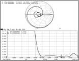
이와 같은, 기존의 차량용 필름 안테나의 정재파비(VSWR)를 도 3을 참조하여살펴보면, 방송 주파수 대역(예를 들어, 일본의 경우 470~770MHz)에서 고르지 못한 정재파비가 발생되는 것을 알 수 있다.Looking at the standing wave ratio (VSWR) of the conventional vehicle film antenna as described above with reference to Figure 3, it can be seen that uneven standing wave ratio occurs in the broadcast frequency band (for example, 470 ~ 770MHz in Japan).
즉, 470MHz에서의 11:1이고, 500MHz에서는 9:17, 600MHz에서는 1.5:1, 700MHz에서는 2:1, 770MHz에서는 2.5:1로 편중된 정재파비로 인하여 수신 주파수 대역에서 감도가 특정 채널에 치우쳐지는 문제점이 발생 되었다. 아울러, 도 2에서와 같이, 기존의 차량용 필름 안테나는 그 크기로 인해 차량 유리 전면 또는 후면(특히, 일본의 경우 유리 전면에 부착됨)에 부착시 운전자의 시야 확보를 방해할 수 있다는 문제점 또한 가지고 있다.In other words, due to the standing wave ratio biased to 11: 1 at 470 MHz, 9:17 at 500 MHz, 1.5: 1 at 600 MHz, 2: 1 at 700 MHz, and 2.5: 1 at 770 MHz, sensitivity is biased to a specific channel in the reception frequency band. A problem has occurred. In addition, as shown in FIG. 2, the conventional vehicle film antenna has a problem that it may interfere with the driver's visibility when attached to the front or rear of the vehicle glass (particularly, in the case of Japan, attached to the front of the glass). have.
따라서, 기존의 차량용 필름 안테나가 가지는 편중된 정재파비로 인한 특정 채널에 감도가 치우쳐지는 문제점과 안테나 크기로 인한 운전자의 시야 확보 방해 문제점을 동시에 해결할 수 있는 차량용 소형 필름 안테나의 개발이 절실히 요구된다.Therefore, there is an urgent need for the development of a small film antenna for a vehicle that can simultaneously solve a problem in which a sensitivity is biased to a specific channel due to the biased standing wave ratio of a conventional vehicle film antenna and a problem of obstructing the driver's view due to the antenna size.
본 발명의 실시예는 기존의 차량용 필름 안테나가 가지는 편중된 정재파비로 인한 특정 채널에 감도가 치우쳐지는 문제점을 해결하기 위한 차량용 필름 안테나를 제공하고자 한다.An embodiment of the present invention is to provide a vehicle film antenna for solving the problem that the sensitivity is biased in a specific channel due to the biased standing wave ratio of the existing vehicle film antenna.
또한, 본 발명의 실시예는 기존의 차량용 필름 안테나의 크기로 인한 운전자의 시야 확보 방해 문제점을 해결하기 위한 차량용 소형 필름 안테나를 제공하고자 한다.In addition, an embodiment of the present invention is to provide a small film antenna for a vehicle for solving the problem of obstructing the visibility of the driver due to the size of the conventional vehicle film antenna.
본 발명의 실시예들에 의한 다른 기술적 해결 과제는 하기의 설명에 의해 이해될 수 있으며, 이는 특허청구범위에 나타낸 수단 및 그 조합에 의해 실현될 수 있다.Other technical problems by the embodiments of the present invention can be understood by the following description, which can be realized by the means and combinations thereof shown in the claims.
본 발명의 일 실시예에 따른 차량용 필름 안테나 장치는, 소정 주파수 대역의 방송 신호를 수신하는 필름 안테나; 상기 필름 안테나에서 수신된 방송 신호를 입력받아 방송 수신이 가능하도록 신호 처리를 수행하는 안테나 회로부; 상기 필름 안테나의 급전단과 상기 안테나 회로부의 방송 신호 입력단 사이에 연결되는 제1 인덕터; 및 상기 필름 안테나의 접지단과 접지면 사이에 연결되는 제2 인덕터;를 포함한다.Vehicle film antenna apparatus according to an embodiment of the present invention, the film antenna for receiving a broadcast signal of a predetermined frequency band; An antenna circuit unit configured to receive a broadcast signal received from the film antenna and perform signal processing to enable broadcast reception; A first inductor connected between a feed end of the film antenna and a broadcast signal input end of the antenna circuit unit; And a second inductor connected between a ground end of the film antenna and a ground plane.
또한, 본 발명의 일 실시예에 따른 차량용 필름 안테나 장치는, 급전단과 연결되는 제1 방사체, 및 상기 제1 방사체와 일정간격 이격되어 접지면과 연결되는 제2 방사체를 포함하며, 소정 주파수 대역의 방송 신호를 수신하는 필름 안테나; 및 상기 필름 안테나에서 수신된 방송 신호를 입력받아 방송 수신이 가능하도록 신호 처리를 수행하는 안테나 회로부;를 포함하며, 상기 필름 안테나의 제2 방사체의 종단부가 "U"형상 또는 "-90도 회전된 ㄷ"형상으로 구부러지게 형성된다.In addition, the vehicle film antenna apparatus according to an embodiment of the present invention, a first radiator connected to the feed end, and a second radiator connected to the ground plane spaced apart from the first radiator a predetermined frequency band, A film antenna for receiving a broadcast signal; And an antenna circuit unit configured to receive a broadcast signal received from the film antenna and perform signal processing to enable broadcast reception, wherein an end portion of the second radiator of the film antenna is “U” shaped or rotated about −90 degrees. Bend into shape.
본 발명의 실시예에 의하면, 기존의 차량용 필름 안테나가 가지는 편중된 정재파비를 방송 수신 주파수 대역에서 균등하게 만들어 줌으로써 특정 채널에 치우쳐지는 감도 문제를 해결할 수 있게 된다.According to the exemplary embodiment of the present invention, the biased standing wave ratio of the conventional vehicle film antenna is equalized in the broadcast reception frequency band, thereby solving the sensitivity problem that is biased to a specific channel.
또한, 본 발명의 실시예에 따르면, 차량용 필름 안테나의 크기를 기존 안테나의 반으로 줄임으로써 운전자의 시야를 더 넓게 확보해 주는 차량용 필름 안테나를 제공할 수 있게 된다.In addition, according to an embodiment of the present invention, it is possible to provide a vehicle film antenna for securing a wider field of view of the driver by reducing the size of the vehicle film antenna to half of the existing antenna.
따라서, 본 발명의 실시예에 의하면, 성능적인 측면에서 차량에 탑승하여 방송을 수신할 때에 방송의 끊김 현상 없이 방송을 수신할 수 있으며, 기능적인 측면에서 기존 안테나에 비해 크기를 소형화시켜 운전자의 시야 확보를 더 넓게 할 수 있다는 효과를 가진다.Therefore, according to an embodiment of the present invention, when receiving a broadcast in a vehicle in terms of performance, it is possible to receive the broadcast without interruption of the broadcast, and in terms of functionality, the size of the driver is reduced compared to the existing antenna in the driver's field of view. This has the effect of making the acquisition wider.
도 1은 기존의 차량용 필름 안테나 장치에 대한 구성도이다.
도 2는 기존의 차량용 필름 안테나의 패턴을 나타낸 도면이다.
도 3은 기존의 차량용 필름 안테나의 정재파비(VSWR)를 나타낸 그래프이다.
도 4는 본 발명의 일실시예에 따른 차량용 필름 안테나 장치에 대한 구성도이다.
도 5는 본 발명의 일실시예에 따른 차량용 필름 안테나의 패턴을 나타낸 도면이다.
도 6은 본 발명의 실시예에 따른 차량용 필름 안테나의 정재파비(VSWR)를 나타낸 그래프이다.
도 7은 기존 차량용 필름 안테나의 크기와 본 발명의 실시예에 따른 차량용 필름 안테나의 크기를 비교한 도면이다.1 is a block diagram of a conventional vehicle film antenna device.
2 is a view showing a pattern of a conventional vehicle film antenna.
3 is a graph showing the standing wave ratio (VSWR) of the conventional vehicle film antenna.
4 is a block diagram of a vehicle film antenna apparatus according to an embodiment of the present invention.
5 is a view showing a pattern of the vehicle film antenna according to an embodiment of the present invention.
6 is a graph showing the standing wave ratio (VSWR) of the vehicle film antenna according to an embodiment of the present invention.
7 is a view comparing the size of the conventional vehicle film antenna and the size of the vehicle film antenna according to an embodiment of the present invention.
이하, 첨부된 도면들을 참조하여 본 발명의 일 실시예에 대해 구체적으로 설명하기로 한다. 그러나 이는 예시적 실시예에 불과하며 본 발명은 이에 제한되지 않는다.Hereinafter, with reference to the accompanying drawings will be described in detail an embodiment of the present invention. However, this is only an exemplary embodiment and the present invention is not limited thereto.
본 발명을 설명함에 있어서, 본 발명과 관련된 공지기술에 대한 구체적인 설명이 본 발명의 요지를 불필요하게 흐릴 수 있다고 판단되는 경우에는 그 상세한 설명을 생략하기로 한다. 그리고, 후술되는 용어들은 본 발명에서의 기능을 고려하여 정의된 용어들로서 이는 사용자, 운용자의 의도 또는 관례 등에 따라 달라질 수 있다. 그러므로 그 정의는 본 명세서 전반에 걸친 내용을 토대로 내려져야 할 것이다.In the following description, a detailed description of known functions and configurations incorporated herein will be omitted when it may make the subject matter of the present invention rather unclear. The following terms are defined in consideration of the functions of the present invention, and may be changed according to the intention or custom of the user, the operator, and the like. Therefore, the definition should be based on the contents throughout this specification.
이하의 설명에 있어서, 연결 또는 결합 이와 유사한 의미의 용어는 일 구성요소에서 다른 구성요소로 직접 연결 또는 결합되는 것뿐만이 아니라 다른 구성요소를 거쳐 전달되는 것도 포함한다.
In the following description, the terms connection or coupling similarly include not only directly connected to or coupled from one component to another, but also transmitted through other components.
이하, 본 발명의 실시예에 따른 차량용 필름 안테나 장치에 대하여 설명하기로 한다.Hereinafter, a vehicle film antenna apparatus according to an embodiment of the present invention will be described.
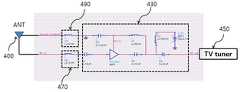
도 4는 본 발명의 일실시예에 따른 차량용 필름 안테나 장치에 대한 구성도이다.4 is a block diagram of a vehicle film antenna apparatus according to an embodiment of the present invention.
도 4를 참조하면, 본 발명의 실시예에 따른 차량용 필름 안테나 장치는 필름 안테나(400), 안테나 회로부(430), 제1 인덕터(470) 및 제2 인덕터(490)를 포함하여 구성된다.Referring to FIG. 4, the vehicular film antenna apparatus according to the embodiment of the present invention includes a
상기 필름 안테나(400)는 차량의 전면이나 후면 유리에 부착되어 소정 주파수 대역의 방송 신호를 수신한다. 본 발명의 실시예에서는 방송 주파수 대역을 470 ~ 770 MHZ 대역으로 한정하여 설명하지만, 상기 주파수 대역은 지역이나 국가에 따라 다를 수 있으며, 방송 주파수 대역에 따라 안테나의 설계가 조금 변경될 수는 있지만 본 발명의 특징이 상기 주파수 대역에 의해 한정되는 것은 아니다. 상기 필름 안테나(400)의 상세 구성에 대하여는 후술할 도 5를 참조하여 설명하기로 한다.The
상기 안테나 회로부(430)는 상기 필름 안테나(400)에서 수신된 방송 신호를 입력받아 상기 입력되는 방송 신호를 방송 수신이 가능하도록 신호 처리를 수행한다. 예를 들어, 상기 안테나 회로부(430)는 상기 입력되는 방송 신호를 증폭하고 잡음을 제거할 수 있는 LNA(Low Noise Amplifier) 회로 일 수 있다. 또한, 상기 안테나 회로부(430)에는 방송 신호 수신을 더 향상시키기 위해 다양한 형태의 회로를 설계할 수 있으며, 도 4에서와 같은 회로 설계 구성에 한정되는 것은 아니다. 상기 안테나 회로부(430)를 통해 처리된 신호는 차량용 단말기의 TV 튜너(450)로 전달되어 차량 탑승자가 원하는 채널의 방송을 수신할 수 있게 된다.The
상기 제1 인덕터(470)는 상기 필름 안테나(400)의 급전단과 상기 안테나 회로부(430)의 방송 신호 입력단 사이에 연결된다. 또한, 상기 제2 인덕터(490)는 상기 필름 안테나(400)의 접지단과 접지면 사이에 연결된다.The
상기 제1 인덕터(470) 및 제 2 인덕터(490)를 필름 안테나(400)와 안테나 회로부(430) 사이에 각각 연결함으로써, 기존의 필름 안테나(100)의 길이에 비해 후술할 본 발명의 필름 안테나(400)의 축소된 길이에 대한 보상을 할 수 있다. 이에 대하여는 후술할 도 6 이하 비교 데이터를 통해서 알 수 있을 것이다. 도 4에서는 상기 제1 인덕터(470)의 값을 12nH로 하고, 제2 인덕터(490)의 값을 22nH로 하여 설계하였지만, 상기 제1 및 제2 인덕터(470, 490)의 값은 필름 안테나(400)의 길이, 넓이 및 재질 또는 안테나 회로부(430)의 회로 설계 구성에 따라 변경될 수 있으며, 위 값에 한정되는 것은 아니다.
By connecting the
도 5는 본 발명의 일실시예에 따른 차량용 필름 안테나(400)의 패턴을 나타낸 도면이다.5 is a view showing a pattern of the
도 5를 참조하면, 본 발명의 차량용 필름 안테나(400)의 패턴은 상기 안테나 회로부(430)의 입력단과 연결되어 수신된 방송 신호를 전달하는 제1 방사체(401), 및 상기 제1 방사체(401)와 일정간격 이격되어 접지면과 연결되는 제2 방사체(403)로 구성된다.Referring to FIG. 5, the pattern of the
상기 제1 방사체(401)와 제2 방사체(403)는 1차적으로 도 5와 같이 세로 길이 방향으로 연장되어 상호 이격된 제1 및 제2 방사체(401, 403) 패턴 사이에서의 커플링에 의한 간접급전 방식이 적용된다.The
또한, 상기 제2 방사체(403)의 세로길이 방향으로 연장된 종단부(405)가 "U"형상 또는 "-90도 회전된 ㄷ"형상으로 구부러지게 형성되어 종단부(405)의 이격된 패턴 사이에 커플링이 추가로 발생된다. 상기 종단부(405)의 구부러지는 형상, 길이 및 각도 그리고 이격 거리는 수신 주파수 대역, 안테나 패턴형상, 안테나 크기 및 커플링의 발생 정도에 따라 소정의 실험을 바탕으로 당업자에 의해 설계 변형 가능하며, 반드시 도 5와 같은 형상, 길이, 각도 또는 이격 거리에 한정되는 것은 아니다. 이와 같이, 제2 방사체(403) 종단부(405)의 형상으로 인한 커플링 발생에 따라 기존 안테나에 비하여 수신 주파수 대역폭을 더 늘릴 수 있게 된다. 이러한 대역폭 확장의 효과에 대하여는 후술할 도 6을 참조하여 확인하기로 한다.
In addition, the
도 6은 본 발명의 실시예에 따른 차량용 필름 안테나의 정재파비(VSWR)를 나타낸 그래프이다.6 is a graph showing the standing wave ratio (VSWR) of the vehicle film antenna according to an embodiment of the present invention.
도 6을 참조하면, 본 발명의 차량용 필름 안테나는 방송 주파수 대역(470 ~770MHz) 전체에 걸쳐 정재파비(VSWR) 2:1 이하의 균등한 특성을 보여주고 있다. 또한, 본 발명의 경우, 도 3의 기존 필름 안테나에 비하여 수신 주파수 대역폭이 더 넓어진 것을 확인할 수 있을 것이다.Referring to FIG. 6, the vehicular film antenna of the present invention has an equivalent characteristic of standing wave ratio (VSWR) of 2: 1 or less over the broadcasting frequency band (470 to 770 MHz). In addition, in the case of the present invention, it can be seen that the reception frequency bandwidth is wider than the conventional film antenna of FIG.
하기 표 1은 기존의 차량용 필름 안테나와 본 발명의 차량용 필름 안테나의 감도를 비교한 데이터이다. 주파수단위는 [MHz]이며, 감도단위는 [dBm]이다.Table 1 is a data comparing the sensitivity of the conventional vehicle film antenna and the vehicle film antenna of the present invention. The frequency unit is [MHz], and the sensitivity unit is [dBm].

기존의 차량용 필름 안테나의 경우 도 3에서와 같이 편중된 정재파비로 인하여 표 1에서와 같이 수신 주파수 대역(470~770MHz)에서 감도가 특정 채널에 치우쳐지는 문제점(예를 들어, V-pol의 경우, 533.143MHz에서는 -46이고, 767.143MHz에서는 -17)이 있다는 것을 알 수 있으며, 본 발명의 경우 도 6에서와 같이 2:1 이하의 균등한 정재파비 특성으로 인해 수신 주파수 전대역(470~770MHz)에서 기존에 비하여 감도 특성이 우수하게 나타남을 알 수 있다.
In the case of the conventional vehicle film antenna, the sensitivity is biased to a specific channel in the reception frequency band (470 to 770 MHz) as shown in Table 1 due to the biased standing wave ratio as shown in FIG. 3 (for example, in the case of V-pol, It can be seen that there is -46 at 533.143 MHz, and -17 at 767.143 MHz. In the present invention, due to the uniform standing wave ratio characteristic of 2: 1 or less, as shown in FIG. It can be seen that the sensitivity characteristic is superior to the conventional.
또한, 도 7에서와 같이, 기존 차량용 필름 안테나의 크기와 본 발명의 실시예에 따른 차량용 필름 안테나의 크기를 비교해보면, 기존 안테나의 경우 가로*세로가 115.5*109 mm2 이고, 본 발명의 안테나의 경우 가로*세로가 60*65.5 mm2 로 기존에 비하여 전체적인 크기가 반으로 줄어들었음을 알 수 있을 것이다. 이러한 본 발명의 필름 안테나 길이의 축소에 대한 보상은 앞서 도 4에서 설명한 바와 같이, 필름 안테나(400)의 급전단과 접지단에 각각 제1 인덕터(470)와 제2 인덕터(490)를 직렬로 연결함으로써 길이 축소에 대한 보상을 할 수 있는 것이다.
In addition, as shown in Figure 7, when comparing the size of the film antenna for the vehicle film according to an embodiment of the present invention and the size of the existing antenna, the width of the existing antenna * vertical length is 115.5 * 109 mm2 , the antenna of the present invention In this case, the width * length is 60 * 65.5 mm2 and the overall size is reduced by half. Compensation for the reduction in the length of the film antenna of the present invention as described above in Figure 4, the
상술한 바와 같이, 본 발명의 실시예에 따르면, 필름 안테나(400)의 급전단과 접지단에 각각 직렬로 제1 인덕터와 제2 인덕터를 연결하고, 필름 안테나의 접지면과 연결되는 제2 방사체의 세로 길이 방향의 종단부를 "u"자 형상 또는 "-90도 회전된 ㄷ"자 형상으로 함으로써, 기존의 차량용 필름 안테나가 가지는 편중된 정재파비를 수신 주파수 대역에서 균등하게 만들어 줌으로써 특정 채널에 치우쳐지는 감도 문제를 해결할 수 있게 됨과 동시에 차량용 필름 안테나의 크기를 기존 안테나의 반으로 줄임으로써 운전자의 시야를 더 넓게 확보해 줄 수 있게 된다.
As described above, according to the embodiment of the present invention, the first inductor and the second inductor are connected in series to the feed end and the ground end of the
이상에서 대표적인 실시 예를 통하여 본 발명에 대하여 상세하게 설명하였으나, 본 발명이 속하는 기술분야에서 통상의 지식을 가진 자는 상술한 실시 예에 대하여 본 발명의 범주에서 벗어나지 않는 한도 내에서 다양한 변형이 가능함을 이해할 것이다. 그러므로 본 발명의 권리범위는 설명된 실시 예에 국한되어 정해져서는 안 되며, 후술하는 특허청구범위뿐만 아니라 이 특허청구범위와 균등한 것들에 의해 정해져야 한다.Although the present invention has been described in detail with reference to exemplary embodiments above, those skilled in the art to which the present invention pertains can make various modifications without departing from the scope of the present invention. I will understand. Therefore, the scope of the present invention should not be limited to the described embodiments, but should be defined by the claims below and equivalents thereof.
400 : 필름 안테나 430 : 안테나 회로부
450 : TV 튜너 470 : 제1 인덕터
490 : 제2 인덕터 401 : 제1 방사체
403 : 제2 방사체 405 : 제2방사체의 종단부400: film antenna 430: antenna circuit portion
450: TV tuner 470: first inductor
490: second inductor 401: first radiator
403: second radiator 405: end of the second radiator
Claims (7)
Translated fromKorean상기 필름 안테나에서 수신된 방송 신호를 입력받아 방송 수신이 가능하도록 신호 처리를 수행하는 안테나 회로부;
상기 필름 안테나의 급전단과 상기 안테나 회로부의 방송 신호 입력단 사이에 연결되는 제1 인덕터; 및
상기 필름 안테나의 접지단과 접지면 사이에 연결되는 제2 인덕터;를 포함하는, 차량용 필름 안테나 장치.
A film antenna for receiving a broadcast signal of a predetermined frequency band;
An antenna circuit unit configured to receive a broadcast signal received from the film antenna and perform signal processing to enable broadcast reception;
A first inductor connected between a feed end of the film antenna and a broadcast signal input end of the antenna circuit unit; And
And a second inductor connected between a ground end of the film antenna and a ground plane.
상기 필름 안테나는,
상기 안테나 회로부의 방송 신호 입력단과 연결되어 수신된 방송 신호를 전달하는 제1 방사체; 및
상기 제1 방사체와 일정간격 이격되어 접지면과 연결되는 제2 방사체;를 포함하며,
상기 제2 방사체의 종단부가 "U"형상 또는 "-90도 회전된 ㄷ"형상으로 구부러지게 형성되는, 차량용 필름 안테나 장치.
The method of claim 1,
The film antenna,
A first radiator connected to a broadcast signal input terminal of the antenna circuit unit to transmit a received broadcast signal; And
And a second radiator spaced apart from the first radiator at a predetermined interval and connected to a ground plane.
The end portion of the second radiator is formed to be bent in a "U" shape or "-" rotated "-90 degrees, the film antenna apparatus for a vehicle.
상기 필름 안테나에서 수신된 방송 신호를 입력받아 방송 수신이 가능하도록 신호 처리를 수행하는 안테나 회로부;를 포함하며,
상기 필름 안테나의 제2 방사체의 종단부가 "U"형상 또는 "-90도 회전된 ㄷ"형상으로 구부러지게 형성되는, 차량용 필름 안테나 장치.
A film antenna including a first radiator connected to a feed end, and a second radiator spaced apart from the first radiator by a predetermined distance and connected to a ground plane, the film antenna receiving a broadcast signal of a predetermined frequency band; And
And an antenna circuit unit configured to receive a broadcast signal received from the film antenna and perform signal processing to enable broadcast reception.
The end portion of the second radiator of the film antenna is formed to be bent in a "U" shape or "-" rotated by -90 degrees shape, the film antenna apparatus for a vehicle.
상기 필름 안테나의 급전단과 상기 안테나 회로부의 방송 신호 입력단 사이에 연결되는 제1 인덕터; 및
상기 필름 안테나의 접지단과 접지면 사이에 연결되는 제2 인덕터;를 더 포함하는, 차량용 필름 안테나 장치.
The method of claim 3, wherein
A first inductor connected between a feed end of the film antenna and a broadcast signal input end of the antenna circuit unit; And
And a second inductor connected between a ground end of the film antenna and a ground plane.
상기 필름 안테나는,
차량의 전면 또는 후면 유리에 부착되는, 차량용 필름 안테나 장치.
The method according to claim 1 or 3,
The film antenna,
A film antenna apparatus for a vehicle, which is attached to the front or rear glass of the vehicle.
상기 필름 안테나가 수신하는 소정 주파수 대역은,
470~770MHz 대역인, 차량용 필름 안테나 장치.
The method according to claim 1 or 3,
The predetermined frequency band received by the film antenna,
Automotive film antenna device, 470 ~ 770MHz band.
상기 안테나 회로부는,
수신된 방송 신호를 증폭하고 잡음을 제거하는 LNA(Low Noise Amplifier) 회인, 차량용 필름 안테나 장치.The method according to claim 1 or 3,
The antenna circuit unit,
A low noise amplifier (LNA) circuit for amplifying a received broadcast signal and removing noise.
Priority Applications (2)
| Application Number | Priority Date | Filing Date | Title |
|---|---|---|---|
| KR1020100114986AKR101174699B1 (en) | 2010-11-18 | 2010-11-18 | Film Antenna Apparatus For Using In Car |
| JP2011245661AJP2012109966A (en) | 2010-11-18 | 2011-11-09 | Film antenna unit for vehicle |
Applications Claiming Priority (1)
| Application Number | Priority Date | Filing Date | Title |
|---|---|---|---|
| KR1020100114986AKR101174699B1 (en) | 2010-11-18 | 2010-11-18 | Film Antenna Apparatus For Using In Car |
Publications (2)
| Publication Number | Publication Date |
|---|---|
| KR20120053719Atrue KR20120053719A (en) | 2012-05-29 |
| KR101174699B1 KR101174699B1 (en) | 2012-08-16 |
Family
ID=46269808
Family Applications (1)
| Application Number | Title | Priority Date | Filing Date |
|---|---|---|---|
| KR1020100114986AExpired - Fee RelatedKR101174699B1 (en) | 2010-11-18 | 2010-11-18 | Film Antenna Apparatus For Using In Car |
Country Status (2)
| Country | Link |
|---|---|
| JP (1) | JP2012109966A (en) |
| KR (1) | KR101174699B1 (en) |
Cited By (8)
| Publication number | Priority date | Publication date | Assignee | Title |
|---|---|---|---|---|
| USD775600S1 (en) | 2014-10-01 | 2017-01-03 | Samsung Electronics Co., Ltd. | Portable electronic device |
| USD779450S1 (en) | 2014-10-01 | 2017-02-21 | Samsung Electronics Co., Ltd. | Portable electronic device |
| USD781275S1 (en) | 2014-10-01 | 2017-03-14 | Samsung Electronics Co., Ltd. | Portable electronic device |
| USD784972S1 (en) | 2014-10-01 | 2017-04-25 | Samsung Electronics Co., Ltd. | Portable electronic device |
| USD785586S1 (en) | 2014-10-01 | 2017-05-02 | Samsung Electronics Co., Ltd. | Portable electronic device |
| USD795855S1 (en) | 2014-10-01 | 2017-08-29 | Samsung Electronics Co., Ltd. | Portable electronic device |
| USD797713S1 (en) | 2014-10-01 | 2017-09-19 | Samsung Electronics Co., Ltd. | Portable electronic device |
| USD803818S1 (en) | 2014-10-01 | 2017-11-28 | Samsung Electronics Co., Ltd. | Portable electronic device |
Families Citing this family (2)
| Publication number | Priority date | Publication date | Assignee | Title |
|---|---|---|---|---|
| JP6064521B2 (en)* | 2012-10-30 | 2017-01-25 | ミツミ電機株式会社 | Film antenna device |
| KR102267709B1 (en)* | 2017-03-24 | 2021-06-23 | 삼성전자주식회사 | Electronic device comprising antenna |
Family Cites Families (3)
| Publication number | Priority date | Publication date | Assignee | Title |
|---|---|---|---|---|
| JP2842581B2 (en)* | 1994-03-07 | 1999-01-06 | 日本板硝子株式会社 | Antenna-switchable in-vehicle antenna |
| JP3700372B2 (en)* | 1997-01-31 | 2005-09-28 | 旭硝子株式会社 | Glass antenna device for vehicle |
| JP4898469B2 (en)* | 2007-01-29 | 2012-03-14 | マスプロ電工株式会社 | Mobile reception system |
- 2010
- 2010-11-18KRKR1020100114986Apatent/KR101174699B1/ennot_activeExpired - Fee Related
- 2011
- 2011-11-09JPJP2011245661Apatent/JP2012109966A/enactivePending
Cited By (17)
| Publication number | Priority date | Publication date | Assignee | Title |
|---|---|---|---|---|
| USD775600S1 (en) | 2014-10-01 | 2017-01-03 | Samsung Electronics Co., Ltd. | Portable electronic device |
| USD776073S1 (en) | 2014-10-01 | 2017-01-10 | Samsung Electronics Co., Ltd. | Portable electronic device |
| USD776075S1 (en) | 2014-10-01 | 2017-01-10 | Samsung Electronics Co., Ltd. | Portable electronic device |
| USD777130S1 (en) | 2014-10-01 | 2017-01-24 | Samsung Electronics Co., Ltd. | Portable electronic device |
| USD777698S1 (en) | 2014-10-01 | 2017-01-31 | Samsung Electronics Co., Ltd. | Portable electronic device |
| USD778890S1 (en) | 2014-10-01 | 2017-02-14 | Samsung Electronics Co., Ltd. | Portable electronic device |
| USD778869S1 (en) | 2014-10-01 | 2017-02-14 | Samsung Electronics Co., Ltd. | Portable electronic device |
| USD779469S1 (en) | 2014-10-01 | 2017-02-21 | Samsung Electronics Co., Ltd. | Portable electronic device |
| USD779450S1 (en) | 2014-10-01 | 2017-02-21 | Samsung Electronics Co., Ltd. | Portable electronic device |
| USD781275S1 (en) | 2014-10-01 | 2017-03-14 | Samsung Electronics Co., Ltd. | Portable electronic device |
| USD784972S1 (en) | 2014-10-01 | 2017-04-25 | Samsung Electronics Co., Ltd. | Portable electronic device |
| USD784974S1 (en) | 2014-10-01 | 2017-04-25 | Samsung Electronics Co., Ltd. | Portable electronic device |
| USD785586S1 (en) | 2014-10-01 | 2017-05-02 | Samsung Electronics Co., Ltd. | Portable electronic device |
| USD788752S1 (en) | 2014-10-01 | 2017-06-06 | Samsung Electronics Co., Ltd. | Portable electronic device |
| USD795855S1 (en) | 2014-10-01 | 2017-08-29 | Samsung Electronics Co., Ltd. | Portable electronic device |
| USD797713S1 (en) | 2014-10-01 | 2017-09-19 | Samsung Electronics Co., Ltd. | Portable electronic device |
| USD803818S1 (en) | 2014-10-01 | 2017-11-28 | Samsung Electronics Co., Ltd. | Portable electronic device |
Also Published As
| Publication number | Publication date |
|---|---|
| JP2012109966A (en) | 2012-06-07 |
| KR101174699B1 (en) | 2012-08-16 |
Similar Documents
| Publication | Publication Date | Title |
|---|---|---|
| KR101174699B1 (en) | Film Antenna Apparatus For Using In Car | |
| JP5153300B2 (en) | antenna | |
| JP3925364B2 (en) | Antenna and diversity receiver | |
| EP3101728B1 (en) | Glass antenna for vehicle and rear window glass with glass antenna for vehicle | |
| JP2008271551A (en) | Multiband antenna device for automobile | |
| CN202977703U (en) | Glass antenna and window glass | |
| JP7228466B2 (en) | antenna device | |
| KR102038558B1 (en) | Antenna device for vehicle | |
| US20140191911A1 (en) | Antenna Assembly | |
| US6924771B2 (en) | Multi-meandered antennas with multiple bands and single input | |
| KR20120068102A (en) | Glass adhesion type integration exterior antenna | |
| US20240291139A1 (en) | Antenna module and wireless communication device having same | |
| US6369768B1 (en) | Automotive on glass antenna with parallel tuned feeder | |
| KR100853652B1 (en) | Terrestrial DMB / DAB Receiver with Built-in Antenna | |
| JP2005229140A (en) | Antenna for vehicle | |
| KR20180042744A (en) | Module Integrated Antenna System For Vehicle | |
| CN101785142B (en) | Vehicle antenna device | |
| EP2109182B1 (en) | Integrated miniaturized RDS/DAB TMC antenna, communications device and method of integration | |
| JP2006211546A (en) | On-vehicle receiver | |
| US11056776B2 (en) | Antenna arrangement for a vehicle | |
| KR100727465B1 (en) | Car Antenna Unit | |
| US20060116071A1 (en) | Receiver integrated satellite digital audio radio antenna system | |
| KR20130014246A (en) | Multi-band receiving active antenna using active antenna impedance matching circuit | |
| JP5653384B2 (en) | Retransmission device | |
| JP2002204112A (en) | Vehicle antenna device |
Legal Events
| Date | Code | Title | Description |
|---|---|---|---|
| A201 | Request for examination | ||
| PA0109 | Patent application | St.27 status event code:A-0-1-A10-A12-nap-PA0109 | |
| PA0201 | Request for examination | St.27 status event code:A-1-2-D10-D11-exm-PA0201 | |
| R18-X000 | Changes to party contact information recorded | St.27 status event code:A-3-3-R10-R18-oth-X000 | |
| D13-X000 | Search requested | St.27 status event code:A-1-2-D10-D13-srh-X000 | |
| D14-X000 | Search report completed | St.27 status event code:A-1-2-D10-D14-srh-X000 | |
| E902 | Notification of reason for refusal | ||
| PE0902 | Notice of grounds for rejection | St.27 status event code:A-1-2-D10-D21-exm-PE0902 | |
| R18-X000 | Changes to party contact information recorded | St.27 status event code:A-3-3-R10-R18-oth-X000 | |
| E13-X000 | Pre-grant limitation requested | St.27 status event code:A-2-3-E10-E13-lim-X000 | |
| P11-X000 | Amendment of application requested | St.27 status event code:A-2-2-P10-P11-nap-X000 | |
| P13-X000 | Application amended | St.27 status event code:A-2-2-P10-P13-nap-X000 | |
| E701 | Decision to grant or registration of patent right | ||
| PE0701 | Decision of registration | St.27 status event code:A-1-2-D10-D22-exm-PE0701 | |
| PG1501 | Laying open of application | St.27 status event code:A-1-1-Q10-Q12-nap-PG1501 | |
| PN2301 | Change of applicant | St.27 status event code:A-3-3-R10-R13-asn-PN2301 St.27 status event code:A-3-3-R10-R11-asn-PN2301 | |
| GRNT | Written decision to grant | ||
| PR0701 | Registration of establishment | St.27 status event code:A-2-4-F10-F11-exm-PR0701 | |
| PR1002 | Payment of registration fee | St.27 status event code:A-2-2-U10-U11-oth-PR1002 Fee payment year number:1 | |
| PG1601 | Publication of registration | St.27 status event code:A-4-4-Q10-Q13-nap-PG1601 | |
| R18-X000 | Changes to party contact information recorded | St.27 status event code:A-5-5-R10-R18-oth-X000 | |
| FPAY | Annual fee payment | Payment date:20150706 Year of fee payment:4 | |
| PR1001 | Payment of annual fee | St.27 status event code:A-4-4-U10-U11-oth-PR1001 Fee payment year number:4 | |
| FPAY | Annual fee payment | Payment date:20160809 Year of fee payment:5 | |
| PR1001 | Payment of annual fee | St.27 status event code:A-4-4-U10-U11-oth-PR1001 Fee payment year number:5 | |
| P22-X000 | Classification modified | St.27 status event code:A-4-4-P10-P22-nap-X000 | |
| R18-X000 | Changes to party contact information recorded | St.27 status event code:A-5-5-R10-R18-oth-X000 | |
| FPAY | Annual fee payment | Payment date:20170807 Year of fee payment:6 | |
| PR1001 | Payment of annual fee | St.27 status event code:A-4-4-U10-U11-oth-PR1001 Fee payment year number:6 | |
| R18-X000 | Changes to party contact information recorded | St.27 status event code:A-5-5-R10-R18-oth-X000 | |
| FPAY | Annual fee payment | Payment date:20180807 Year of fee payment:7 | |
| PR1001 | Payment of annual fee | St.27 status event code:A-4-4-U10-U11-oth-PR1001 Fee payment year number:7 | |
| R18-X000 | Changes to party contact information recorded | St.27 status event code:A-5-5-R10-R18-oth-X000 | |
| FPAY | Annual fee payment | Payment date:20190806 Year of fee payment:8 | |
| PR1001 | Payment of annual fee | St.27 status event code:A-4-4-U10-U11-oth-PR1001 Fee payment year number:8 | |
| PR1001 | Payment of annual fee | St.27 status event code:A-4-4-U10-U11-oth-PR1001 Fee payment year number:9 | |
| PN2301 | Change of applicant | St.27 status event code:A-5-5-R10-R13-asn-PN2301 St.27 status event code:A-5-5-R10-R11-asn-PN2301 | |
| PC1903 | Unpaid annual fee | St.27 status event code:A-4-4-U10-U13-oth-PC1903 Not in force date:20210810 Payment event data comment text:Termination Category : DEFAULT_OF_REGISTRATION_FEE | |
| PN2301 | Change of applicant | St.27 status event code:A-5-5-R10-R13-asn-PN2301 St.27 status event code:A-5-5-R10-R11-asn-PN2301 | |
| R18-X000 | Changes to party contact information recorded | St.27 status event code:A-5-5-R10-R18-oth-X000 | |
| PC1903 | Unpaid annual fee | St.27 status event code:N-4-6-H10-H13-oth-PC1903 Ip right cessation event data comment text:Termination Category : DEFAULT_OF_REGISTRATION_FEE Not in force date:20210810 | |
| R18-X000 | Changes to party contact information recorded | St.27 status event code:A-5-5-R10-R18-oth-X000 |