KR20120051692A - Spinal implant set including a quick closure - Google Patents
Spinal implant set including a quick closureDownload PDFInfo
- Publication number
- KR20120051692A KR20120051692AKR1020127003832AKR20127003832AKR20120051692AKR 20120051692 AKR20120051692 AKR 20120051692AKR 1020127003832 AKR1020127003832 AKR 1020127003832AKR 20127003832 AKR20127003832 AKR 20127003832AKR 20120051692 AKR20120051692 AKR 20120051692A
- Authority
- KR
- South Korea
- Prior art keywords
- head
- quick closure
- screw
- bone screw
- clamping element
- Prior art date
- Legal status (The legal status is an assumption and is not a legal conclusion. Google has not performed a legal analysis and makes no representation as to the accuracy of the status listed.)
- Withdrawn
Links
Images


Classifications
- A—HUMAN NECESSITIES
- A61—MEDICAL OR VETERINARY SCIENCE; HYGIENE
- A61B—DIAGNOSIS; SURGERY; IDENTIFICATION
- A61B17/00—Surgical instruments, devices or methods
- A61B17/56—Surgical instruments or methods for treatment of bones or joints; Devices specially adapted therefor
- A61B17/58—Surgical instruments or methods for treatment of bones or joints; Devices specially adapted therefor for osteosynthesis, e.g. bone plates, screws or setting implements
- A61B17/68—Internal fixation devices, including fasteners and spinal fixators, even if a part thereof projects from the skin
- A61B17/70—Spinal positioners or stabilisers, e.g. stabilisers comprising fluid filler in an implant
- A61B17/7001—Screws or hooks combined with longitudinal elements which do not contact vertebrae
- A61B17/7032—Screws or hooks with U-shaped head or back through which longitudinal rods pass
- A—HUMAN NECESSITIES
- A61—MEDICAL OR VETERINARY SCIENCE; HYGIENE
- A61B—DIAGNOSIS; SURGERY; IDENTIFICATION
- A61B17/00—Surgical instruments, devices or methods
- A61B17/56—Surgical instruments or methods for treatment of bones or joints; Devices specially adapted therefor
- A61B17/58—Surgical instruments or methods for treatment of bones or joints; Devices specially adapted therefor for osteosynthesis, e.g. bone plates, screws or setting implements
- A61B17/68—Internal fixation devices, including fasteners and spinal fixators, even if a part thereof projects from the skin
- A61B17/84—Fasteners therefor or fasteners being internal fixation devices
- A61B17/86—Pins or screws or threaded wires; nuts therefor
- A—HUMAN NECESSITIES
- A61—MEDICAL OR VETERINARY SCIENCE; HYGIENE
- A61F—FILTERS IMPLANTABLE INTO BLOOD VESSELS; PROSTHESES; DEVICES PROVIDING PATENCY TO, OR PREVENTING COLLAPSING OF, TUBULAR STRUCTURES OF THE BODY, e.g. STENTS; ORTHOPAEDIC, NURSING OR CONTRACEPTIVE DEVICES; FOMENTATION; TREATMENT OR PROTECTION OF EYES OR EARS; BANDAGES, DRESSINGS OR ABSORBENT PADS; FIRST-AID KITS
- A61F2/00—Filters implantable into blood vessels; Prostheses, i.e. artificial substitutes or replacements for parts of the body; Appliances for connecting them with the body; Devices providing patency to, or preventing collapsing of, tubular structures of the body, e.g. stents
- A61F2/02—Prostheses implantable into the body
- A61F2/30—Joints
- A61F2/44—Joints for the spine, e.g. vertebrae, spinal discs
Landscapes
- Health & Medical Sciences (AREA)
- Orthopedic Medicine & Surgery (AREA)
- Life Sciences & Earth Sciences (AREA)
- Neurology (AREA)
- Surgery (AREA)
- Engineering & Computer Science (AREA)
- Biomedical Technology (AREA)
- General Health & Medical Sciences (AREA)
- Veterinary Medicine (AREA)
- Heart & Thoracic Surgery (AREA)
- Public Health (AREA)
- Animal Behavior & Ethology (AREA)
- Molecular Biology (AREA)
- Medical Informatics (AREA)
- Nuclear Medicine, Radiotherapy & Molecular Imaging (AREA)
- Cardiology (AREA)
- Oral & Maxillofacial Surgery (AREA)
- Transplantation (AREA)
- Vascular Medicine (AREA)
- Surgical Instruments (AREA)
- Prostheses (AREA)
Abstract
Translated fromKoreanDescription
Translated fromKorean본 발명은 청구항 제1항의 전제부에 따른 퀵 클로저 디바이스(quick closure device)를 포함하는 척추 임플란트 세트에 관한 것이다.The present invention relates to a set of spinal implants comprising a quick closure device according to the preamble of
이러한 클로저 디바이스는 통상적으로 척추의 외과 처치에 사용된다. 환자가 나이를 먹어감에 따라, 이들은 보다 종종 골다공증을 갖게 되어, 나사의 고정 능력이 제한된다. 따라서, 연결 요소들은, 이상적으로 뼈의 나사 고정이 영향을 받지 않고 유지되는 방식으로 최소한의 응력으로 나사 헤드에 고정시킬 수 있는 것이 특히 중요하다.Such closure devices are typically used for surgical treatment of the spine. As patients age, they more often have osteoporosis, which limits the screw's ability to fix. It is therefore particularly important that the connecting elements can be secured to the screw head with minimal stress, in such a way that ideally the screw fixation of the bone is maintained unaffected.
다양한 퀵 클로저가 당업계에 공지되어 있고, 이들 모두는 이하에서 나타내는 하나 또는 몇 가지 단점의 문제가 있다.Various quick closures are known in the art, all of which suffer from one or several disadvantages, which are presented below.
이들 비교의 평가로서, 종래 기술의 퀵 클로저는, 내부적 또는 외부적으로 활주식으로 부착 가능한 퀵 클로저, 내부적 또는 외부적으로 회전식으로 부착 가능한 퀵 클로저, 내부 또는 외부 베요넷형(bayonet-like) 퀵 클로저로 분류된다.As an evaluation of these comparisons, the prior art quick closures are quick closures that are internally or externally slidable, quick closures that are internally or externally rotatable, internal or external bayonet-like quick closures. Classified as
내부적으로 활주식으로 부착 가능한 퀵 클로저 중에서, 이하의 것들이 예를 들어 당업계에 공지되어 있고, 이는 삽입 방향의 단부 정지부를 갖고 활주식으로 삽입 가능한 EP0672388호(Metz-Stavenhagen et al., 1995); 캡의 상승 후에 양방향으로 단부 정지부를 갖고 2 방향으로 삽입 가능한 US6110172호(Jackson, 1998); 단부 정지부 없이 삽입 가능한 US6302888호(Mellinger, 1999); 단부 정지부를 갖지 않고 활주식 뿐만 아니라 피봇식으로 삽입 가능한 EP0836436호(Wisnewski et al., 1995)이다.Among the internally slideable quick closures, the following are known, for example, in the art: EP0672388 (Metz-Stavenhagen et al., 1995), which is slideably insertable with end stops in the insertion direction; US6110172 (Jackson, 1998) capable of inserting in two directions with end stops in both directions after the cap is raised; US6302888 (Mellinger, 1999) insertable without end stops; EP0836436 (Wisnewski et al., 1995), which does not have end stops and can be inserted slidingly as well as pivotally.
외부 활주식으로 부착 가능한 퀵 클로저 중에서, 이하의 것들이 예를 들어 당업계에서 공지되어 있고, 이는 정지부 없이 높은 간극 요구사항을 갖고 뼈 나사 부근의 나사 헤드의 저부에서 삽입 가능한 DE4107480호(Ulrich et al., 1991) 및 US6139549호(keller, 1997)이다.Among the externally slideable quick closures, the following are known in the art, for example, DE4107480 (Ulrich et al.), Which has a high clearance requirement without stops and can be inserted at the bottom of the screw head near the bone screw. , 1991) and US6139549 (keller, 1997).
내부 회전식으로 부착 가능한 퀵 클로저 중에서, 이하의 것들이 예를 들어 당업계에서 공지되어 있고, 단부 정지부를 갖고 일방향으로 회전식으로 삽입 가능한 EP1119304호(Yuan, 1998); 단부 정지부없이 일방향으로 회전식으로 삽입 가능한 US6258090호(Jackson, 2000); 단부 정지부를 갖지 않고 2 방향으로 회전식으로 삽입 가능한 US6652526호(Arafiles, 2001); 봉재의 위치 설정 보조부(aid)로써 양방향으로 회전식으로 삽입 가능한 US6786903호(Lin, 2002)이다.Among the internally attachable quick closures, the following are known, for example, in the art, and EP1119304 (Yuan, 1998) rotatably inserted in one direction with end stops; US6258090 (Jackson, 2000), which is rotatable in one direction without end stops; US6652526 (Arafiles, 2001) rotatably insertable in two directions without end stops; US6786903 (Lin, 2002), which is rotatable in both directions as a positioning aid of the bar.
외부 회전식으로 삽입 가능한 퀵 클로저 중에서, 이하의 것들이 예를 들어 당업계에 공지되어 있고, 단부 정지부 없이 양방향으로 회전식으로 삽입 가능한 US5346493호(Stahurski et at., 1993); 단부 정지부를 갖지 않고 일방향으로 회전식으로 삽입 가능한 US6251112호(Jackson, 2000); 단부 정지부를 갖고 일방향으로 회전식으로 삽입 가능한 EP1190678호(Bono et al., 2001)이다.Among the externally rotatable quick closures, the following are known, for example, in the art, and US5346493 (Stahurski et at., 1993) rotatably insertable in both directions without end stops; US6251112 (Jackson, 2000) rotatable in one direction without end stops; EP1190678 (Bono et al., 2001) with end stops and rotatably inserted in one direction.
내부 및 외부 베요넷형 퀵 클로저 중에서, 이하의 것들이 예를 들어 당업계에 공지되어 있고, 단부 정지부를 갖고 일측으로부터 나사 헤드의 저부에서 삽입 가능한 DE9403231호(Aesculap, 1994); 단부 정지부를 갖고 일측으로부터 나사 헤드의 상부에서 삽입 가능한 US7235075호(Metz-Stavenhagen, 2003)이다.Among the inner and outer bayonet type quick closures, the following are known, for example, in the art, DE9403231 (Aesculap, 1994) which has an end stop and is insertable at the bottom of the screw head from one side; US7235075 (Metz-Stavenhagen, 2003) having an end stop and insertable at the top of the screw head from one side.
이에 대해, 활주식으로 삽입 가능한 퀵 클로저의 주요한 단점은 비교적 높은 모멘트가 통상적으로 나사의 위치에서 제어되지 않는 상황을 생성할 위험을 갖는, 외과의에 의해 척추 수술에 사용되는 긴 기기에 인가되어야 한다는 점이다. 회전식 삽입 가능한 퀵 클로저에 대해, 기기를 따라 필요한 토크는 항상 동일하게 유지된다. 따라서 동적 안정화 시스템의 보다 빈번한 적용으로 인해 플라스틱 봉재가 보다 자주 사용되기 때문에, 양측으로부터의 회전식 삽입성은 중요하다. 그러나, 이는 안정성의 이유로 금속 봉재보다 크고, 따라서 더 많은 공간이 필요하다.In this regard, the major drawback of the slidably insertable quick closure is that it must be applied to long instruments used in spinal surgery by surgeons, with the risk of creating a situation where relatively high moments are not normally controlled at the position of the screw. to be. For rotary insertable quick closures, the torque required along the machine remains the same at all times. Therefore, rotational insertability from both sides is important because plastic rods are used more frequently due to more frequent applications of dynamic stabilization systems. However, it is larger than metal rods for stability reasons and therefore requires more space.
척추경(pedicle) 입구에서의 제한된 공간의 상황에서, 일측에서만 회전식으로 삽입 가능한 퀵 클로저는 횡방향 프로세스 또는 파셋 조인트(facet joint)에 의해 붕괴를 야기할 수 있고, 이는 양측으로부터의 회전식 삽입성의 경우에서보다 개연성이 높다. 단부 정지부를 갖지 않는 퀵 클로저에서, 나사에 대한 억세스가 어려운 추가의 기기에 의해 유지되지 않고는 나사는 조여질 수 없다. 따라서, 조임 방향으로의 단부 정지부는 뼈 기초부(bone bed)를 보존하면서 클램핑 나사를 고정하는 반면, 조임 방향에 대향하는 단부 정지부는 뼈 기초부를 보존하면서 클램핑 나사를 해제한다. 양방향의 단부 정지부는 양방향으로의 뼈 기초부를 최적으로 보존한다.In situations of limited space at the pedicle inlet, a quick closure that can only be inserted rotatably on one side can cause collapse by transverse processes or facet joints, which in the case of rotatable inserts from both sides Probability higher than In quick closures that do not have end stops, the screws cannot be tightened without being retained by further appliances with difficult access to the screws. Thus, the end stop in the tightening direction locks the clamping screw while preserving the bone bed, while the end stop opposite the tightening direction releases the clamping screw while preserving the bone base. End stops in both directions optimally preserve the bone base in both directions.
또한 동적 안정화 시스템의 플라스틱 봉재의 증가된 치수의 결과로서, 나사 헤드와 척추경 입구 사이에 남겨진 공간은 퀵 클로저 커플링을 위해 대부분 불충분하다. 이러한 경우, 퀵 클로저가 나사 헤드의 상부에 배열되는 시스템에만 적용 가능하다.In addition, as a result of the increased dimensions of the plastic rod of the dynamic stabilization system, the space left between the screw head and the pedicle inlet is mostly insufficient for quick closure coupling. In this case, it is only applicable to systems in which the quick closure is arranged on top of the screw head.
따라서, 본 발명의 목적은, 조립하기 쉽고 조작 응력으로부터 뼈 나사의 뼈 기초부를 보다 잘 보호하는 방식으로, 뼈 나사의 연결 요소를 고정하기 위한 퀵 클로저를 포함하는 척추 임플란트 세트를 설계하는 것이다.It is therefore an object of the present invention to design a set of spinal implants comprising quick closures for securing the connection elements of the bone screws in a manner that is easy to assemble and better protects the bone foundations of the bone screws from operational stresses.
이러한 임플란트 세트는 청구항 제1항에 따라 제안된다. 추가 청구항들은 그의 바람직한 실시예들을 한정한다.Such a set of implants is proposed according to
따라서 퀵 클로저는 양방향(시계 방향 및 반시계 방향)으로 부착 가능하고, 양방향으로 나사 상에 작용하는 토크를 취할(take up) 수 있도록 사실상 로크 가능하다.The quick closure is thus attachable in both directions (clockwise and counterclockwise) and virtually lockable to take up torque acting on the screw in both directions.
바람직하게는, 본 발명은 청구항 제1항에 한정된 퀵 클로저가 좌측으로부터 또는 우측으로부터 나사 헤드의 돌기 상에서 회전식으로 부착 가능한 것을 제안한다. 또한, 나사 헤드의 퀵 클로저의 회전식 부착은 미리 조립된 클램핑 요소의 중심 설정 특성에 의해 보조될 수 있다.Preferably, the present invention proposes that the quick closure as defined in
바람직한 사용에서, 퀵 클로저는 수동으로 또는 클램핑 나사에 의해 후퇴되어, 퀵 클로저의 후크는 나사 헤드의 돌기와 나사 헤드의 돌기의 리세스 내의 퀵 클로저의 필러와 결합하여 이들을 로크한다. 이러한 방식으로, 클램핑 요소로부터 뼈 나사로 전달된 토크는 뼈 나사의 뼈 기초부에 추가적인 응력을 인가하지 않고 퀵 클로저에 의해 취해질 수 있다. 또한, 나사 헤드의 안내 때문에, 클램핑 요소는 연결 요소로부터 뼈 나사로 종방향 힘을 직접적으로 전달할 수 있다.In a preferred use, the quick closures are retracted manually or by clamping screws, such that the hooks of the quick closures engage and lock the fillers of the quick closures in the recesses of the protrusions of the screw heads and the protrusions of the screw heads. In this way, the torque transmitted from the clamping element to the bone screw can be taken by the quick closure without applying additional stress to the bone base of the bone screw. In addition, because of the guiding of the screw head, the clamping element can transfer the longitudinal force directly from the connecting element to the bone screw.
본 발명은 단지 예시적인 실시예를 도시하는 첨부 도면을 참조하여 바람직한 예시적인 실시예에 의해 이하에서 보다 상세히 설명된다.The invention is explained in more detail below by means of preferred exemplary embodiments with reference to the accompanying drawings which show merely exemplary embodiments.
도 1은 임플란트 세트 조립체의 3D 도면.
도 2a는 뼈 나사, 퀵 클로저 및 클램핑 요소의 분해도.
도 2b는 뼈 나사, 퀵 클로저 및 클램핑 요소의 조립도.
도 3a는 로크되고 클램핑되지 않은 퀵 클로저의 단면도.
도 3b는 로크되고 클램핑된 퀵 클로저의 단면도.1 is a 3D view of an implant set assembly.
2A is an exploded view of the bone screw, quick closure and clamping element.
2B shows an assembly view of the bone screw, quick closure and clamping element.
3A is a cross-sectional view of a locked and unclamped quick closure.
3B is a cross-sectional view of the locked and clamped quick closure.
도 1은 조립된 상태의 뼈 나사(1), 연결 요소(2), 클램핑 요소(3) 및 퀵 클로저(4)를 도시한다.1 shows the
도 2a는 나사 헤드 돌기들(1a), 돌기들(1a) 사이의 리세스(1b), 뼈 나사 헤드의 절반부의 클램핑 요소 가이드(1c)뿐만 아니라, 연결 요소의 시트(1d)를 갖는 뼈 나사(1); 클램핑 요소 가이드(1c)와 끼워맞춤되는 표면(3a)과 그의 나사부(3b)를 갖는 클램핑 요소(3); 나사 헤드 돌기(1a)와 끼워맞춤되는 후크(4a)와, 리세스(1b)에 끼워맞춤되는 필러(4b)를 갖는 퀵 클로저(4)를 도시한다.2a shows a bone screw with
도 2b는 후크(4a)가 나사 헤드 돌기(1a)의 아래로부터 나사 헤드 돌기(1a)와 접촉하는 뼈 나사(1), 리세스(1b) 내에 삽입된 퀵 클로저(4)의 필러(4b) 및 클램핑 요소 가이드(1c)에 삽입된 클램핑 요소(3)의 클램핑 요소 표면(3a)을 도시한다.2B shows the
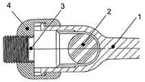
도 3a는 연결 요소(2), 클램핑 요소(3)를 갖는 뼈 나사(1)의 종방향 섹션과, 로크되었지만 클램핑되지 않은 상태의 퀵 클로저(4)의 단면을 도시한다.FIG. 3a shows the connecting
도 3b는 뼈 나사(1)와 연결 요소(2), 클램핑 요소(3)의 종방향 섹션과, 로크되고 클램핑된 상태의 퀵 클로저(4)의 단면을 도시한다.3b shows a cross section of the
이러한 조립체는 척추경 나사(1) 내의 연결 요소(2)의 신속하고 확실한 부착을 제공한다.This assembly provides a quick and secure attachment of the connecting
특히, 클램핑 요소 가이드(1c)는, 연결 요소(2)의 종방향으로 클램핑 요소(3)가 안정하게 보유되는 충분한 랩(wrap) 각도를 커버한다.In particular, the
클로저를 사용하기 위해, 연결 요소(2)는 뼈 나사(1)의 헤드(1a)에 위치된다. 후퇴 위치의 클램핑 요소(3)를 갖는 퀵 클로저(4)는 클램핑 요소 가이드(1c)의 하방으로 연결 요소를 활주시켜 나사 헤드에 세팅된다. 퀵 클로저(4)는 후크(4a)와 필러(4b)를 지지하는 로킹 연장부가 나사 헤드 돌기(1a) 사이를 통과하거나 정지하는 위치에서 헤드에 세팅된다. 퀵 클로저(4)는 회전하여, 퀵 클로저(4)가 후퇴될 때 필러(4b)는 리세스(1b) 내로 활주한다. 이러한 후방 운동은 돌기(1a)를 타격하는 후크(4a)에 의해 제한된다. 이어서, 클램핑 요소(3)는 나사부(3b)의 접근 가능한 단부에 부착된 공구를 이용하여 나사 고정(screwed down)된다. 연결 요소(2)를 타격하면(도 3b 참조), 연결 요소(2)뿐만 아니라 퀵 클로저(4)에 힘을 가하여 이들의 로크 위치에 유지시킨다. 퀵 클로저(4)는 이제 포지티브 인터로킹에 의해 로크되고: 축방향으로, 후크(4a)는 나사 헤드 돌기(1a)와 결합하고, 양방향의 회전이 헤드 돌기들(1a) 사이의 리세스(1b)에 놓여진 필러(4b)에 의해 방지되어 필러(4b)의 양측의 면 상에 정지면들을 제공한다.To use the closure, the connecting
전술한 설명에 기초하여, 당업자는 청구범위에 의해 한정된 보호 범위를 벗어나지 않고 변형을 유도할 수 있다.Based on the foregoing description, those skilled in the art can induce modifications without departing from the scope of protection defined by the claims.
Claims (15)
Translated fromKorean상기 연결 요소를 위한 시트(1d)를 갖는 헤드를 구비하고 축방향으로 연장하는, 적어도 하나의 뼈 나사(1),
퀵 클로저 요소(4) 및
클램핑 요소(3)를 포함하는 척추 임플란트 세트에 있어서,
상기 퀵 클로저 요소는 적어도 후크부(4a)와 필러부(4b)를 구비하고,
상기 뼈 나사의 헤드는 적어도 하나의 축방향 정지면과 그 외향 측방향으로 대면하는 적어도 두 개의 트위스트 정지면들을 구비하고,
상기 클램핑 요소는 상기 뼈 나사의 헤드에 삽입 가능하고 상기 퀵 클로저 요소와의 조절식 연결을 구비하여,
상기 후크부는 상기 퀵 클로저 요소가 상기 뼈 나사에 부착될 때, 두 개의 트위스트 정지면들과 양방향으로 주연 방향으로 상기 축방향 정지면 및 상기 필러부와 축방향으로 결합 가능하고, 상기 뼈 나사에 대한 회전과 축방향 제거에 대해 상기 퀵 클로저 요소를 로크하도록, 상기 나사의 헤드에 상기 연결 요소(2)가 위치되면, 상기 클램핑 요소는 상기 나사의 헤드와 상기 퀵 클로저 요소 사이에서 축방향 힘을 생성하도록 조절 가능한 것을 특징으로 하는, 척추 임플란트 세트.Connecting element (2),
At least one bone screw 1 having an head axially extending and having a seat 1d for the connecting element,
Quick closure element (4) and
In the set of spinal implants comprising the clamping element (3),
The quick closure element has at least a hook portion 4a and a filler portion 4b,
The head of the bone screw has at least one axial stop face and at least two twist stop faces facing outwardly,
The clamping element is insertable into the head of the bone screw and has an adjustable connection with the quick closure element,
The hook portion is axially engageable with the axial stop surface and the pillar portion in a circumferential direction in two directions with the two twist stop surfaces when the quick closure element is attached to the bone screw, When the connecting element 2 is positioned in the head of the screw to lock the quick closure element for rotation and axial removal, the clamping element generates an axial force between the head of the screw and the quick closure element. Set of spinal implants, characterized in that adjustable to.
Applications Claiming Priority (2)
| Application Number | Priority Date | Filing Date | Title |
|---|---|---|---|
| CH1114/09 | 2009-07-16 | ||
| CH11142009 | 2009-07-16 |
Publications (1)
| Publication Number | Publication Date |
|---|---|
| KR20120051692Atrue KR20120051692A (en) | 2012-05-22 |
Family
ID=42651090
Family Applications (1)
| Application Number | Title | Priority Date | Filing Date |
|---|---|---|---|
| KR1020127003832AWithdrawnKR20120051692A (en) | 2009-07-16 | 2010-07-01 | Spinal implant set including a quick closure |
Country Status (7)
| Country | Link |
|---|---|
| US (1) | US9149299B2 (en) |
| EP (1) | EP2453818B1 (en) |
| JP (1) | JP2012532705A (en) |
| KR (1) | KR20120051692A (en) |
| CA (1) | CA2767562A1 (en) |
| RU (1) | RU2012100640A (en) |
| WO (1) | WO2011006268A1 (en) |
Families Citing this family (5)
| Publication number | Priority date | Publication date | Assignee | Title |
|---|---|---|---|---|
| EP2591738A1 (en)* | 2011-11-14 | 2013-05-15 | Biedermann Technologies GmbH & Co. KG | Polyaxial bone anchoring device |
| CN105434087B (en)* | 2016-01-13 | 2017-09-29 | 贵州省黔南布依族苗族自治州中医医院 | A kind of spinal implant dynamic prestressing force clamping device and its installation method |
| CN105455927B (en)* | 2016-01-13 | 2017-06-20 | 李海明 | A kind of spinal implant two dimension prestressing clamping device and its installation method |
| US11571244B2 (en)* | 2019-05-22 | 2023-02-07 | Nuvasive, Inc. | Posterior spinal fixation screws |
| TWD227883S (en)* | 2023-03-08 | 2023-10-01 | 博晟生醫股份有限公司 | Medical implantable device set |
Family Cites Families (34)
| Publication number | Priority date | Publication date | Assignee | Title |
|---|---|---|---|---|
| DE4107480C2 (en) | 1991-03-08 | 1994-09-22 | Heinrich Ulrich | Pedicle screw for implants to correct and stabilize the spine |
| US5257993A (en) | 1991-10-04 | 1993-11-02 | Acromed Corporation | Top-entry rod retainer |
| DE9402839U1 (en) | 1994-02-22 | 1994-04-14 | Howmedica GmbH, 24232 Schönkirchen | Device for setting up a spine with damaged vertebrae |
| DE9403231U1 (en) | 1994-02-26 | 1994-04-21 | Aesculap Ag, 78532 Tuttlingen | Surgical implant |
| US5562663A (en) | 1995-06-07 | 1996-10-08 | Danek Medical, Inc. | Implant interconnection mechanism |
| DE29606468U1 (en) | 1996-04-09 | 1997-08-07 | Waldemar Link GmbH & Co, 22339 Hamburg | Spinal fixator |
| US6565565B1 (en)* | 1998-06-17 | 2003-05-20 | Howmedica Osteonics Corp. | Device for securing spinal rods |
| US6110172A (en) | 1998-07-31 | 2000-08-29 | Jackson; Roger P. | Closure system for open ended osteosynthesis apparatus |
| CA2346176C (en) | 1998-10-06 | 2008-03-18 | Surgical Dynamics, Inc. | Device for securing spinal rods |
| US6302888B1 (en) | 1999-03-19 | 2001-10-16 | Interpore Cross International | Locking dovetail and self-limiting set screw assembly for a spinal stabilization member |
| FR2795623B1 (en)* | 1999-07-01 | 2001-11-30 | Gerard Vanacker | SYSTEM FOR OSTEOSYNTHESIS ON THE SPINE, PARTICULARLY FOR THE STABILIZATION OF VERTEBRAES, FIXING AND ANCILLARY ELEMENT FOR SUCH A SYSTEM |
| DE10005385A1 (en)* | 2000-02-07 | 2001-08-09 | Ulrich Gmbh & Co Kg | Pedicle screw |
| US6251112B1 (en)* | 2000-04-18 | 2001-06-26 | Roger P. Jackson | Thin profile closure cap for open ended medical implant |
| US6258090B1 (en) | 2000-04-28 | 2001-07-10 | Roger P. Jackson | Closure for open ended medical implant and removal tool |
| US6755829B1 (en) | 2000-09-22 | 2004-06-29 | Depuy Acromed, Inc. | Lock cap anchor assembly for orthopaedic fixation |
| US6652526B1 (en) | 2001-10-05 | 2003-11-25 | Ruben P. Arafiles | Spinal stabilization rod fastener |
| CN1221217C (en) | 2002-01-24 | 2005-10-05 | 英属维京群岛商冠亚生技控股集团股份有限公司 | Rotary button fixator for vertebration fixing |
| WO2003086204A2 (en)* | 2002-04-09 | 2003-10-23 | Neville Alleyne | Bone fixation apparatus |
| US7842073B2 (en)* | 2002-04-18 | 2010-11-30 | Aesculap Ii, Inc. | Screw and rod fixation assembly and device |
| WO2003096916A1 (en) | 2002-05-21 | 2003-11-27 | Peter Metz-Stavenhagen | Anchoring element for securing a rod on a vertebra |
| US8328850B2 (en)* | 2002-12-23 | 2012-12-11 | Choice Spine, Lp | Device for immobilizing a connecting rod in an osseous anchoring element of a rachidian implant |
| US7811310B2 (en)* | 2005-05-04 | 2010-10-12 | Spinefrontier, Inc | Multistage spinal fixation locking mechanism |
| GB0521585D0 (en)* | 2005-10-22 | 2005-11-30 | Depuy Int Ltd | A spinal support rod |
| JP2010505541A (en)* | 2006-10-05 | 2010-02-25 | ジャヴィン・ピアス | Anchor assembly for spinal implant system |
| JP5085730B2 (en)* | 2007-06-28 | 2012-11-28 | スピナル エレメンツ,インク. | Spine stabilization device |
| US20090076550A1 (en)* | 2007-09-18 | 2009-03-19 | Ortho Development Corporation | Spinal fixation system connectors |
| US20090105756A1 (en)* | 2007-10-23 | 2009-04-23 | Marc Richelsoph | Spinal implant |
| EP2074957B1 (en)* | 2007-12-31 | 2013-04-17 | Spinelab AG | Pedicle screw with a locking device for attaching a rod to stabilise the spine |
| EP2082697B1 (en)* | 2008-01-28 | 2011-02-09 | Spinelab AG | Pedicular screw with a locking device |
| EP2355725B1 (en)* | 2008-09-05 | 2017-03-08 | Synthes GmbH | Bone fixation assembly |
| US20100292739A1 (en)* | 2009-05-15 | 2010-11-18 | Warsaw Orthopedic, Inc. | Bone Screws With Improved Locking Mechanisms |
| US8236032B2 (en)* | 2009-10-20 | 2012-08-07 | Depuy Spine, Inc. | Spinal implant with a flexible extension element |
| WO2011059732A1 (en)* | 2009-10-28 | 2011-05-19 | Bonovo Orthopedics, Inc. | Pedicle screws and methods of use |
| US20120215263A1 (en)* | 2011-02-23 | 2012-08-23 | Choon Sung Lee | Extensible pedicle screw coupling device |
- 2010
- 2010-07-01KRKR1020127003832Apatent/KR20120051692A/ennot_activeWithdrawn
- 2010-07-01CACA2767562Apatent/CA2767562A1/ennot_activeAbandoned
- 2010-07-01RURU2012100640/14Apatent/RU2012100640A/ennot_activeApplication Discontinuation
- 2010-07-01EPEP10730690.4Apatent/EP2453818B1/enactiveActive
- 2010-07-01USUS13/383,615patent/US9149299B2/enactiveActive
- 2010-07-01JPJP2012519861Apatent/JP2012532705A/enactivePending
- 2010-07-01WOPCT/CH2010/000169patent/WO2011006268A1/enactiveApplication Filing
Also Published As
| Publication number | Publication date |
|---|---|
| CA2767562A1 (en) | 2011-01-20 |
| US9149299B2 (en) | 2015-10-06 |
| EP2453818A1 (en) | 2012-05-23 |
| EP2453818B1 (en) | 2015-12-16 |
| US20120116456A1 (en) | 2012-05-10 |
| JP2012532705A (en) | 2012-12-20 |
| RU2012100640A (en) | 2013-08-27 |
| WO2011006268A1 (en) | 2011-01-20 |
Similar Documents
| Publication | Publication Date | Title |
|---|---|---|
| JP6109172B2 (en) | Multiaxial pedicle screw with provisional fastening means | |
| EP2085040B1 (en) | Tool for holding or guiding a receiving part for connecting a shank of a bone anchoring element to a rod | |
| CA2736808C (en) | Orthopaedic device to be associated with the outside of a bone | |
| US9492209B2 (en) | Extension device for a bone anchor, in particular for minimally invasive surgery | |
| ES2974088T3 (en) | Medical technical instrument for provisional fixation of a polyaxial pedicle screw | |
| CA2397112C (en) | Device for securing spinal rods | |
| ES2379027T3 (en) | Intermedullary locking device lockable | |
| US7842071B2 (en) | Transverse connector | |
| KR101325250B1 (en) | Locking assembly for securing a rod member in a receiver part for use in spinal or trauma surgery, bone anchoring device with such a locking assembly and tool therefor | |
| EP1119304B1 (en) | Device for securing spinal rods | |
| US20100004694A1 (en) | Screw assembly | |
| US20120245640A1 (en) | Polyaxial pedicle screw and fixation system kit comprising the screw | |
| TW201309256A (en) | Polyaxial bone anchoring device with enlarged pivot angle | |
| KR20120051692A (en) | Spinal implant set including a quick closure | |
| TWI695702B (en) | Bone screw and percutaneous minimally invasive pedicle fixation system | |
| WO2014120443A2 (en) | Aiming instrument | |
| JP6662891B2 (en) | Spinal retainer and spinal fixation system including the same | |
| CA2574142C (en) | Medical system, body implant, adaptor device and method for spatially adjusting an aiming device relative to the body implant | |
| US10575881B2 (en) | Self-locking screwdriver | |
| CA2756461A1 (en) | Pedicle screw | |
| AU2017313725A1 (en) | Bone fusion device, system and methods | |
| US20240398444A1 (en) | A polyaxial spinal screw | |
| US20220361927A1 (en) | Partially blocked pedical screw ii | |
| EP3287087B1 (en) | Fixation system for spinal instrumentation |
Legal Events
| Date | Code | Title | Description |
|---|---|---|---|
| PA0105 | International application | St.27 status event code:A-0-1-A10-A15-nap-PA0105 | |
| P11-X000 | Amendment of application requested | St.27 status event code:A-2-2-P10-P11-nap-X000 | |
| P13-X000 | Application amended | St.27 status event code:A-2-2-P10-P13-nap-X000 | |
| PG1501 | Laying open of application | St.27 status event code:A-1-1-Q10-Q12-nap-PG1501 | |
| PC1203 | Withdrawal of no request for examination | St.27 status event code:N-1-6-B10-B12-nap-PC1203 | |
| WITN | Application deemed withdrawn, e.g. because no request for examination was filed or no examination fee was paid |