KR20120047231A - Expanding intervertebral device and methods of use - Google Patents
Expanding intervertebral device and methods of useDownload PDFInfo
- Publication number
- KR20120047231A KR20120047231AKR1020127001209AKR20127001209AKR20120047231AKR 20120047231 AKR20120047231 AKR 20120047231AKR 1020127001209 AKR1020127001209 AKR 1020127001209AKR 20127001209 AKR20127001209 AKR 20127001209AKR 20120047231 AKR20120047231 AKR 20120047231A
- Authority
- KR
- South Korea
- Prior art keywords
- arms
- end portion
- spinal stabilization
- arm
- elongate
- Prior art date
- Legal status (The legal status is an assumption and is not a legal conclusion. Google has not performed a legal analysis and makes no representation as to the accuracy of the status listed.)
- Withdrawn
Links
- 238000000034methodMethods0.000titleclaimsdescription20
- 239000000463materialSubstances0.000claimsdescription72
- 210000000988bone and boneAnatomy0.000claimsdescription42
- 230000004927fusionEffects0.000claimsdescription36
- 230000006641stabilisationEffects0.000claimsdescription30
- 238000011105stabilizationMethods0.000claimsdescription30
- 230000008878couplingEffects0.000claimsdescription18
- 238000010168coupling processMethods0.000claimsdescription18
- 238000005859coupling reactionMethods0.000claimsdescription18
- 230000000670limiting effectEffects0.000claimsdescription16
- 230000004323axial lengthEffects0.000claimsdescription11
- 230000000295complement effectEffects0.000claimsdescription10
- 229910001000nickel titaniumInorganic materials0.000claimsdescription10
- HLXZNVUGXRDIFK-UHFFFAOYSA-Nnickel titaniumChemical compound[Ti].[Ti].[Ti].[Ti].[Ti].[Ti].[Ti].[Ti].[Ti].[Ti].[Ti].[Ni].[Ni].[Ni].[Ni].[Ni].[Ni].[Ni].[Ni].[Ni].[Ni].[Ni].[Ni].[Ni].[Ni]HLXZNVUGXRDIFK-UHFFFAOYSA-N0.000claimsdescription10
- 239000000945fillerSubstances0.000claimsdescription9
- 230000001225therapeutic effectEffects0.000claimsdescription9
- 230000008468bone growthEffects0.000claimsdescription8
- 239000000515collagen spongeSubstances0.000claimsdescription8
- 230000001054cortical effectEffects0.000claimsdescription8
- 108010049931Bone Morphogenetic Protein 2Proteins0.000claimsdescription7
- 102100024506Bone morphogenetic protein 2Human genes0.000claimsdescription7
- 229910000990Ni alloyInorganic materials0.000claimsdescription7
- 229910001069Ti alloyInorganic materials0.000claimsdescription7
- RTAQQCXQSZGOHL-UHFFFAOYSA-NTitaniumChemical compound[Ti]RTAQQCXQSZGOHL-UHFFFAOYSA-N0.000claimsdescription7
- 239000012634fragmentSubstances0.000claimsdescription7
- 230000002829reductive effectEffects0.000claimsdescription7
- 239000010936titaniumSubstances0.000claimsdescription7
- 239000012781shape memory materialSubstances0.000claimsdescription6
- 238000005520cutting processMethods0.000claimsdescription5
- 230000002138osteoinductive effectEffects0.000claimsdescription5
- 239000011800void materialSubstances0.000claimsdescription5
- 102000004127CytokinesHuman genes0.000claimsdescription4
- 108090000695CytokinesProteins0.000claimsdescription4
- 238000004519manufacturing processMethods0.000claimsdescription4
- 230000000921morphogenic effectEffects0.000claimsdescription3
- 230000000278osteoconductive effectEffects0.000claimsdescription3
- 239000002861polymer materialSubstances0.000claimsdescription3
- 238000001816coolingMethods0.000claimsdescription2
- 230000007704transitionEffects0.000claimsdescription2
- 108010007726Bone Morphogenetic ProteinsProteins0.000claims1
- 102000007350Bone Morphogenetic ProteinsHuman genes0.000claims1
- 238000009998heat settingMethods0.000claims1
- 210000004185liverAnatomy0.000claims1
- 230000007246mechanismEffects0.000description11
- 208000002193PainDiseases0.000description7
- 208000008035Back PainDiseases0.000description4
- 239000007943implantSubstances0.000description4
- 238000003780insertionMethods0.000description4
- 230000037431insertionEffects0.000description4
- 230000000087stabilizing effectEffects0.000description4
- 208000008930Low Back PainDiseases0.000description3
- 230000006870functionEffects0.000description3
- 230000006872improvementEffects0.000description3
- 230000033001locomotionEffects0.000description3
- 230000000452restraining effectEffects0.000description3
- 238000011282treatmentMethods0.000description3
- 206010061246Intervertebral disc degenerationDiseases0.000description2
- PXHVJJICTQNCMI-UHFFFAOYSA-NNickelChemical compound[Ni]PXHVJJICTQNCMI-UHFFFAOYSA-N0.000description2
- KDLHZDBZIXYQEI-UHFFFAOYSA-NPalladiumChemical compound[Pd]KDLHZDBZIXYQEI-UHFFFAOYSA-N0.000description2
- 230000006835compressionEffects0.000description2
- 238000007906compressionMethods0.000description2
- 208000037265diseases, disorders, signs and symptomsDiseases0.000description2
- 230000035876healingEffects0.000description2
- 210000003041ligamentAnatomy0.000description2
- BASFCYQUMIYNBI-UHFFFAOYSA-NplatinumChemical compound[Pt]BASFCYQUMIYNBI-UHFFFAOYSA-N0.000description2
- 239000011148porous materialSubstances0.000description2
- 230000002980postoperative effectEffects0.000description2
- 238000011084recoveryMethods0.000description2
- 229910052702rheniumInorganic materials0.000description2
- WUAPFZMCVAUBPE-UHFFFAOYSA-Nrhenium atomChemical compound[Re]WUAPFZMCVAUBPE-UHFFFAOYSA-N0.000description2
- 238000011477surgical interventionMethods0.000description2
- 238000001356surgical procedureMethods0.000description2
- 101150061927BMP2 geneProteins0.000description1
- 208000017234Bone cystDiseases0.000description1
- 206010010356Congenital anomalyDiseases0.000description1
- 102100020760Ferritin heavy chainHuman genes0.000description1
- 101001002987Homo sapiens Ferritin heavy chainProteins0.000description1
- ZOKXTWBITQBERF-UHFFFAOYSA-NMolybdenumChemical compound[Mo]ZOKXTWBITQBERF-UHFFFAOYSA-N0.000description1
- 208000028389Nerve injuryDiseases0.000description1
- 208000012902Nervous system diseaseDiseases0.000description1
- 208000025966Neurological diseaseDiseases0.000description1
- 239000004696Poly ether ether ketoneSubstances0.000description1
- 208000012287ProlapseDiseases0.000description1
- 206010069689Spinal column injuryDiseases0.000description1
- 208000020307Spinal diseaseDiseases0.000description1
- 206010072005Spinal painDiseases0.000description1
- 208000007103SpondylolisthesisDiseases0.000description1
- 229920004695VICTREX™ PEEKPolymers0.000description1
- 230000032683agingEffects0.000description1
- 229910045601alloyInorganic materials0.000description1
- 239000000956alloySubstances0.000description1
- WYTGDNHDOZPMIW-RCBQFDQVSA-NalstonineNatural productsC1=CC2=C3C=CC=CC3=NC2=C2N1C[C@H]1[C@H](C)OC=C(C(=O)OC)[C@H]1C2WYTGDNHDOZPMIW-RCBQFDQVSA-N0.000description1
- 210000003484anatomyAnatomy0.000description1
- 238000013459approachMethods0.000description1
- 230000008901benefitEffects0.000description1
- JUPQTSLXMOCDHR-UHFFFAOYSA-Nbenzene-1,4-diol;bis(4-fluorophenyl)methanoneChemical compoundOC1=CC=C(O)C=C1.C1=CC(F)=CC=C1C(=O)C1=CC=C(F)C=C1JUPQTSLXMOCDHR-UHFFFAOYSA-N0.000description1
- 239000012620biological materialSubstances0.000description1
- 230000036760body temperatureEffects0.000description1
- 230000008859changeEffects0.000description1
- 230000001684chronic effectEffects0.000description1
- 229910017052cobaltInorganic materials0.000description1
- 239000010941cobaltSubstances0.000description1
- GUTLYIVDDKVIGB-UHFFFAOYSA-Ncobalt atomChemical compound[Co]GUTLYIVDDKVIGB-UHFFFAOYSA-N0.000description1
- 239000002131composite materialSubstances0.000description1
- 150000001875compoundsChemical class0.000description1
- 230000007547defectEffects0.000description1
- 230000003412degenerative effectEffects0.000description1
- 230000018044dehydrationEffects0.000description1
- 238000006297dehydration reactionMethods0.000description1
- 201000010099diseaseDiseases0.000description1
- 208000035475disorderDiseases0.000description1
- 238000006073displacement reactionMethods0.000description1
- 230000000694effectsEffects0.000description1
- 238000005516engineering processMethods0.000description1
- 238000001704evaporationMethods0.000description1
- 230000008020evaporationEffects0.000description1
- 238000004299exfoliationMethods0.000description1
- 239000006260foamSubstances0.000description1
- PCHJSUWPFVWCPO-UHFFFAOYSA-NgoldChemical compound[Au]PCHJSUWPFVWCPO-UHFFFAOYSA-N0.000description1
- 229910052737goldInorganic materials0.000description1
- 239000010931goldSubstances0.000description1
- 239000007924injectionSubstances0.000description1
- 238000002347injectionMethods0.000description1
- 238000003698laser cuttingMethods0.000description1
- 230000013011matingEffects0.000description1
- 239000000203mixtureSubstances0.000description1
- 230000004048modificationEffects0.000description1
- 238000012986modificationMethods0.000description1
- 229910052750molybdenumInorganic materials0.000description1
- 239000011733molybdenumSubstances0.000description1
- 238000012544monitoring processMethods0.000description1
- 230000004899motilityEffects0.000description1
- 229940035363muscle relaxantsDrugs0.000description1
- 239000003158myorelaxant agentSubstances0.000description1
- 210000005036nerveAnatomy0.000description1
- 230000008764nerve damageEffects0.000description1
- 229910052759nickelInorganic materials0.000description1
- RVTZCBVAJQQJTK-UHFFFAOYSA-Noxygen(2-);zirconium(4+)Chemical compound[O-2].[O-2].[Zr+4]RVTZCBVAJQQJTK-UHFFFAOYSA-N0.000description1
- 229910052763palladiumInorganic materials0.000description1
- 230000036961partial effectEffects0.000description1
- 230000000149penetrating effectEffects0.000description1
- 230000002093peripheral effectEffects0.000description1
- 238000000554physical therapyMethods0.000description1
- 229910052697platinumInorganic materials0.000description1
- 229920001643poly(ether ketone)Polymers0.000description1
- 229920002530polyetherether ketonePolymers0.000description1
- 229920000642polymerPolymers0.000description1
- 230000008569processEffects0.000description1
- 238000012545processingMethods0.000description1
- 230000009467reductionEffects0.000description1
- 230000002441reversible effectEffects0.000description1
- 229910001285shape-memory alloyInorganic materials0.000description1
- 238000004904shorteningMethods0.000description1
- 210000001032spinal nerveAnatomy0.000description1
- 229910001220stainless steelInorganic materials0.000description1
- 239000010935stainless steelSubstances0.000description1
- 150000003431steroidsChemical class0.000description1
- 239000013589supplementSubstances0.000description1
- 230000000153supplemental effectEffects0.000description1
- 208000011580syndromic diseaseDiseases0.000description1
- 229910052715tantalumInorganic materials0.000description1
- GUVRBAGPIYLISA-UHFFFAOYSA-Ntantalum atomChemical compound[Ta]GUVRBAGPIYLISA-UHFFFAOYSA-N0.000description1
- 238000002560therapeutic procedureMethods0.000description1
- 230000000472traumatic effectEffects0.000description1
- WFKWXMTUELFFGS-UHFFFAOYSA-NtungstenChemical compound[W]WFKWXMTUELFFGS-UHFFFAOYSA-N0.000description1
- 229910052721tungstenInorganic materials0.000description1
- 239000010937tungstenSubstances0.000description1
Images


Classifications
- A—HUMAN NECESSITIES
- A61—MEDICAL OR VETERINARY SCIENCE; HYGIENE
- A61B—DIAGNOSIS; SURGERY; IDENTIFICATION
- A61B17/00—Surgical instruments, devices or methods
- A61B17/56—Surgical instruments or methods for treatment of bones or joints; Devices specially adapted therefor
- A61B17/58—Surgical instruments or methods for treatment of bones or joints; Devices specially adapted therefor for osteosynthesis, e.g. bone plates, screws or setting implements
- A61B17/68—Internal fixation devices, including fasteners and spinal fixators, even if a part thereof projects from the skin
- A61B17/70—Spinal positioners or stabilisers, e.g. stabilisers comprising fluid filler in an implant
- A—HUMAN NECESSITIES
- A61—MEDICAL OR VETERINARY SCIENCE; HYGIENE
- A61B—DIAGNOSIS; SURGERY; IDENTIFICATION
- A61B17/00—Surgical instruments, devices or methods
- A61B17/56—Surgical instruments or methods for treatment of bones or joints; Devices specially adapted therefor
- A61B17/58—Surgical instruments or methods for treatment of bones or joints; Devices specially adapted therefor for osteosynthesis, e.g. bone plates, screws or setting implements
- A61B17/88—Osteosynthesis instruments; Methods or means for implanting or extracting internal or external fixation devices
- A61B17/885—Tools for expanding or compacting bones or discs or cavities therein
- A61B17/8852—Tools for expanding or compacting bones or discs or cavities therein capable of being assembled or enlarged, or changing shape, inside the bone or disc
- A61B17/8858—Tools for expanding or compacting bones or discs or cavities therein capable of being assembled or enlarged, or changing shape, inside the bone or disc laterally or radially expansible
- A—HUMAN NECESSITIES
- A61—MEDICAL OR VETERINARY SCIENCE; HYGIENE
- A61B—DIAGNOSIS; SURGERY; IDENTIFICATION
- A61B17/00—Surgical instruments, devices or methods
- A61B17/56—Surgical instruments or methods for treatment of bones or joints; Devices specially adapted therefor
- A61B17/58—Surgical instruments or methods for treatment of bones or joints; Devices specially adapted therefor for osteosynthesis, e.g. bone plates, screws or setting implements
- A61B17/68—Internal fixation devices, including fasteners and spinal fixators, even if a part thereof projects from the skin
- A61B17/70—Spinal positioners or stabilisers, e.g. stabilisers comprising fluid filler in an implant
- A61B17/7097—Stabilisers comprising fluid filler in an implant, e.g. balloon; devices for inserting or filling such implants
- A61B17/7098—Stabilisers comprising fluid filler in an implant, e.g. balloon; devices for inserting or filling such implants wherein the implant is permeable or has openings, e.g. fenestrated screw
- A—HUMAN NECESSITIES
- A61—MEDICAL OR VETERINARY SCIENCE; HYGIENE
- A61B—DIAGNOSIS; SURGERY; IDENTIFICATION
- A61B17/00—Surgical instruments, devices or methods
- A61B17/56—Surgical instruments or methods for treatment of bones or joints; Devices specially adapted therefor
- A61B17/58—Surgical instruments or methods for treatment of bones or joints; Devices specially adapted therefor for osteosynthesis, e.g. bone plates, screws or setting implements
- A61B17/88—Osteosynthesis instruments; Methods or means for implanting or extracting internal or external fixation devices
- A61B17/8802—Equipment for handling bone cement or other fluid fillers
- A61B17/8805—Equipment for handling bone cement or other fluid fillers for introducing fluid filler into bone or extracting it
- A61B17/8811—Equipment for handling bone cement or other fluid fillers for introducing fluid filler into bone or extracting it characterised by the introducer tip, i.e. the part inserted into or onto the bone
- A—HUMAN NECESSITIES
- A61—MEDICAL OR VETERINARY SCIENCE; HYGIENE
- A61F—FILTERS IMPLANTABLE INTO BLOOD VESSELS; PROSTHESES; DEVICES PROVIDING PATENCY TO, OR PREVENTING COLLAPSING OF, TUBULAR STRUCTURES OF THE BODY, e.g. STENTS; ORTHOPAEDIC, NURSING OR CONTRACEPTIVE DEVICES; FOMENTATION; TREATMENT OR PROTECTION OF EYES OR EARS; BANDAGES, DRESSINGS OR ABSORBENT PADS; FIRST-AID KITS
- A61F2/00—Filters implantable into blood vessels; Prostheses, i.e. artificial substitutes or replacements for parts of the body; Appliances for connecting them with the body; Devices providing patency to, or preventing collapsing of, tubular structures of the body, e.g. stents
- A61F2/02—Prostheses implantable into the body
- A61F2/30—Joints
- A61F2/44—Joints for the spine, e.g. vertebrae, spinal discs
- A—HUMAN NECESSITIES
- A61—MEDICAL OR VETERINARY SCIENCE; HYGIENE
- A61B—DIAGNOSIS; SURGERY; IDENTIFICATION
- A61B17/00—Surgical instruments, devices or methods
- A61B2017/00831—Material properties
- A61B2017/00867—Material properties shape memory effect
Landscapes
- Health & Medical Sciences (AREA)
- Orthopedic Medicine & Surgery (AREA)
- Life Sciences & Earth Sciences (AREA)
- Surgery (AREA)
- Engineering & Computer Science (AREA)
- Biomedical Technology (AREA)
- Animal Behavior & Ethology (AREA)
- Veterinary Medicine (AREA)
- Public Health (AREA)
- Heart & Thoracic Surgery (AREA)
- General Health & Medical Sciences (AREA)
- Molecular Biology (AREA)
- Medical Informatics (AREA)
- Nuclear Medicine, Radiotherapy & Molecular Imaging (AREA)
- Neurology (AREA)
- Cardiology (AREA)
- Oral & Maxillofacial Surgery (AREA)
- Transplantation (AREA)
- Vascular Medicine (AREA)
- Prostheses (AREA)
Abstract
Translated fromKoreanDescription
Translated fromKorean우선권에 대한 참조Reference to priority
본 출원은 2009년 6월 17일자로 출원된 미국 가출원 제61/218,009호의 35 U.S.C.§119(e) 하의 우선권을 주장한다. 2009년 6월 17일자 출원일에 대한 우선권이 본원에서 주장되며 상기 출원의 내용은 그 전체가 본 명세서에 원용된다.This application claims priority under 35 U.S.C. § 119 (e) of US Provisional Application No. 61 / 218,009, filed June 17, 2009. Priority to the filing date of June 17, 2009 is claimed herein and the content of this application is incorporated herein in its entirety.
본 발명은 골 구조물을 안정화 및 유합(fuse)하고 수술후 회복 중에 공간을 유지하기 위한 방법, 시스템 및 장치에 관한 것이다.The present invention relates to methods, systems, and apparatus for stabilizing and fusing bone structures and for maintaining space during postoperative recovery.
상당수의 성인은 요통의 발현을 갖고 있거나 척주의 일부로부터 발생되는 만성 요통을 앓고 있다. 많은 척추 장애는, 통증을 초래하고, 척추의 유연성을 감소시키며, 척추의 하중 지지 능력을 저하시키고, 척추의 길이를 단축시키며, 및/또는 척추의 정상 만곡을 왜곡하는 외상성 척추 손상, 질환 과정, 노화 과정, 및 선천성 이상에 의해 초래된다. 요통을 앓고 있는 많은 사람들은 통증 완화를 위해 외과적 개입에 의존한다.Many adults have chronic low back pain, or have low back pain. Many spinal disorders cause traumatic vertebral injuries, disease processes, which cause pain, reduce spine flexibility, reduce the load-bearing capacity of the spine, shorten the length of the spine, and / or distort normal curvature of the spine. Caused by the aging process, and congenital anomalies. Many people with low back pain rely on surgical intervention to relieve pain.
디스크 퇴화는 요통의 한 원인이 될 수 있다. 나이가 들수록 추간판의 수핵은 유동성이 저하되고 점성이 증가하는 경향이 있다. 추간판의 탈수화 및 기타 퇴행성 효과는 심각한 통증을 초래할 수 있다. 환형 균열도 윤상인대(annulus)의 탈출 또는 파열과 연관될 수 있으며 이는 수핵이 균열을 통해서 팽출 또는 압출되어 척주 또는 척추 신경과 충돌하게 만든다["파열" 또는 "전위(slip)"된 디스크].Disc degeneration can be a cause of back pain. With age, the nucleus pulposus of the intervertebral discs tends to decrease in fluidity and increase in viscosity. Dehydration and other degenerative effects of the intervertebral discs can lead to severe pain. Annular cracks can also be associated with prolapse or rupture of the annulus, which causes the nucleus nucleus to swell or extrude through the crack and impinge on the spinal column or spinal nerve ("rupture" or "slip" disk).
여러 개의 운동 분절에 걸쳐서 발생할 수 있는 척추 변형에 추가적으로, 척추전방전위증(spondylolisthesis)(통상 요추 또는 경추에서의 하나의 추체에 대한 다른 추체의 전방 이동)이 상당한 중심성 및/또는 방사성 통증과 연관된다. 이러한 질환을 앓는 환자는 하중 지지 능력의 감소, 운동성 손실, 극심한 쇠약성 통증을 겪을 수 있으며 때로는 신경 기능에서의 신경 장애를 앓을 수 있다.In addition to spinal deformation that can occur over several segments of motion, spondylolisthesis (usually forward movement of one vertebral body to one vertebrae in the lumbar or cervical spine) is associated with significant central and / or radiological pain. Patients with these disorders may suffer from reduced load bearing capacity, loss of motility, extreme debilitating pain and sometimes neurological disorders in nerve function.
예를 들어 침상 안정, 통증 및 근육 이완 약제, 물리 치료 또는 스테로이드 주사와 같은 척추 통증 치료를 위한 보존 요법의 실패는 환자가 보통 척추 외과적 개입을 추구하게 만든다. 퇴화한 추간판에 대해 덜 침습적이거나, 경피적이거나 최소-침습적인 접근을 제공하도록 의도된 많은 수술 기법, 기구 및 척추 디스크 임플란트가 기술되었다. 추간판 절제술을 수행하고 윤상인대 내에 골성장 재료 또는 생체재료 또는 척추 디스크 임플란트를 식립하기 위한 기구가 윤상인대를 통해서 도입된다. 척추 디스크 임플란트 또는 골성장 재료를 수용하여 유합을 촉진하거나 또는 사전형성된 인공적인 기능적 디스크 교체 임플란트를 수용하기 위해 디스크에 하나 이상의 환형 절개가 이루어진다.Failure of conservative therapies for spinal pain treatments, such as, for example, bed rest, pain and muscle relaxants, physiotherapy or steroid injections, usually results in patients seeking spinal surgical intervention. Many surgical techniques, instruments, and spinal disc implants have been described that are intended to provide a less invasive, percutaneous, or minimally-invasive approach to degenerated intervertebral discs. A device for performing discectomy and placing bone growth material or biomaterial or spinal disc implant in the annulus ligament is introduced through the annulus ligament. One or more annular incisions are made in the disc to accommodate spinal disc implants or bone growth material to facilitate fusion or to accommodate preformed artificial functional disc replacement implants.
이들 기술 중 일부에는 광범위한 신경주위 절제 및 골 전처치가 필요할 수 있다. 또한, 환형 또는 환형주위 구조물의 파열은 안정성의 손실 또는 신경 손상을 초래할 수 있다. 그 결과, 척주는 더 약해질 수 있으며 및/또는 수술이 유발하는 통증 증후군을 초래할 수 있다.Some of these techniques may require extensive pericardiotomy and bone pretreatment. In addition, rupture of the annular or annular structure can result in loss of stability or nerve damage. As a result, the spinal column may be weaker and / or result in a pain syndrome caused by surgery.
본 발명은 골 구조물을 안정화 및 유합하고 수술후 회복 중에 공간을 유지하기 위한 방법, 시스템 및 장치에 관한 것이다.The present invention relates to methods, systems, and apparatus for stabilizing and coalescing bone structures and maintaining space during postoperative recovery.
일 실시예에서는, 원위 단부 부분과 근위 단부 부분을 갖는 복수의 세장형 아암을 갖는 척추 안정화 장치가 개시된다. 세장형 아암은 원위 단부 부분과 근위 단부 부분 사이에 내부 체적을 형성한다. 상기 장치는 또한, 복수의 세장형 아암에 원주방향으로 결합되는 제한 밴드(limit band); 및 상기 내부 체적 내에 배치되는 인장 요소를 갖는다. 상기 복수의 세장형 아암은, 반경방향으로 수축되고 축방향으로 신장되는 강제된 투입(constrained, delivery) 구조에서, 반경방향으로 팽창되고 축방향으로 단축되며 추간판 공간 내에서 해방되도록 구성되는 이완된 전개(relaxed, deployment) 구조로 수동적으로 이행된다.In one embodiment, a spinal stabilization device having a plurality of elongate arms having a distal end portion and a proximal end portion is disclosed. The elongate arm forms an internal volume between the distal end portion and the proximal end portion. The apparatus also includes a limit band circumferentially coupled to the plurality of elongate arms; And a tensioning element disposed within the inner volume. The plurality of elongate arms have a relaxed deployment configured to be radially expanded, shortened in the axial direction and freed in the intervertebral disc space in a forcedly constrained, delivery configuration that contracts in a radial direction and extends in an axial direction. Passive implementation of the (relaxed, deployment) structure.
제한 밴드는 복수의 세장형 아암 중 하나 이상과 일체적일 수 있거나, 또는 제한 밴드는 장치의 외주에 결합되는 별개의 단일 요소일 수 있다. 제한 밴드는 복수의 세장형 아암이 투입 구조에 있을 때 반경방향으로 수축될 수 있으며, 제한 밴드는 복수의 세장형 아암이 전개 구조에 있을 때 반경방향으로 팽창될 수 있다. 제한 밴드는 전개 구조에 있을 때 및 상기 장치가 측방향 벽 하중 하에 있을 때 복수의 아암의 탈구에 저항할 수 있다.The restriction band may be integral with one or more of the plurality of elongate arms, or the restriction band may be a separate single element coupled to the outer periphery of the device. The confinement band can be retracted radially when the plurality of elongate arms are in the input structure, and the confinement band can be expanded in the radial direction when the plurality of elongate arms are in the deployment structure. The limiting band can resist dislocation of the plurality of arms when in the deployment structure and when the device is under lateral wall load.
인장 요소는 연계 막대(linkage rod) 및 로킹 단부 캡을 구비할 수 있다. 연계 막대는 원위 단부 및 근위 단부를 구비할 수 있다. 연계 막대의 원위 단부는 세장형 아암의 원위 단부 부분에 결합될 수 있고 연계 막대의 근위 단부는 로킹 단부 캡에 결합될 수 있다. 로킹 단부 캡은 세장형 아암의 근위 단부 부분에 결합될 수 있다. 연계 막대의 근위 단부는 나사가공될 수 있고 로킹 단부 캡의 상보적 나사부에 결합될 수 있다. 인장 요소는 아암이 전개 구조에 있을 때 아암의 원위 단부 부분과 아암의 근위 단부 부분을 로크시킬 수 있다. 상기 세장형 아암에 수직하게 향하는 압축 하중은 인장 요소에 인장 하중을 유발할 수 있다. 인가되는 원주방향 내측 힘이 상기 복수의 아암을 투입 구조로 압박할(urge) 수 있다.The tension element may have a linkage rod and a locking end cap. The linkage bar may have a distal end and a proximal end. The distal end of the linkage bar can be coupled to the distal end portion of the elongate arm and the proximal end of the linkage bar can be coupled to the locking end cap. The locking end cap may be coupled to the proximal end portion of the elongate arm. The proximal end of the linkage rod may be threaded and coupled to the complementary thread of the locking end cap. The tensioning element may lock the distal end portion of the arm and the proximal end portion of the arm when the arm is in the deployment structure. A compressive load directed perpendicular to the elongate arm can cause a tensile load on the tensioning element. An applied circumferential inner force can urge the plurality of arms into the input structure.
전개 구조에서의 내부 체적은 방추형, 튜브형, 장방형 또는 회전타원체(spheroid) 형상일 수 있다. 복수의 세장형 아암의 전개 구조는 거품기(whisk), 코일, 스프링, 체인-링크, 또는 짠바구니(woven basket) 형상일 수 있다. 내부 체적은 골 성장 재료, 골 이식 재료, 골 공극 충전재, 해면질 골이식재, 피질 골이식재, 해면질 골편, 피질 골편, 골전도성 재료, 골증식성 재료, 골유도성 재료, 골 형태형성(morphogenic) 시토카인, BMP-2, 골재료에 침지된 콜라겐 스폰지, 또는 BMP-2 침지된 콜라겐 스폰지를 포함하는 하나 이상의 치료용 재료로 충전될 수 있다. 인장 요소는 원위 단부 부분 및 근위 단부 부분에서 내부 체적을 밀봉할 수 있다. 인장 요소는 반경방향으로 변위되어 치료용 재료를 내부 체적 내에 배포할 수 있다.The internal volume in the deployment structure can be fusiform, tubular, oblong or spheroidal in shape. The deployment structure of the plurality of elongate arms may be in the shape of whisks, coils, springs, chain-links, or woven baskets. Internal volume includes bone growth material, bone graft material, bone void filler, spongy bone graft material, cortical bone graft material, spongy bone fragment, cortical bone fragment, bone conduction material, osteoproliferative material, osteoinductive material, bone morphogenic cytokines, It may be filled with one or more therapeutic materials, including BMP-2, collagen sponges immersed in bone material, or BMP-2 immersed collagen sponges. The tension element may seal the interior volume at the distal end portion and the proximal end portion. The tension element may be displaced radially to distribute the therapeutic material within the interior volume.
복수의 세장형 아암은 니티놀, 티타늄/니켈 합금, 또는 폴리머 재료일 수 있다. 복수의 세장형 아암은 불균일한 벽 두께 및/또는 폭을 가질 수 있다. 복수의 세장형 아암은 이들 아암이 제한 밴드에 결합되는 곳에서 감소된 벽 두께를 가질 수 있다. 복수의 세장형 아암은 이들 아암이 제한 밴드에 결합되는 곳에서 감소된 폭을 가질 수 있다. 강제된 투입 구조에서의 장치의 외경은 대체로 일정할 수 있다.The plurality of elongate arms may be nitinol, titanium / nickel alloys, or polymeric materials. The plurality of elongate arms may have non-uniform wall thickness and / or width. The plurality of elongate arms may have a reduced wall thickness where these arms are joined to the limiting bands. The plurality of elongate arms may have a reduced width where these arms are coupled to the limiting band. The outer diameter of the device in the forced input structure may be substantially constant.
다른 태양에서는 추체간(interbody) 장치, 인장 요소, 및 캐뉼러 조립체를 갖는 추체간 유합 시스템이 개시된다. 추체간 장치는 원위 단부 부분과 근위 단부 부분을 갖는 복수의 세장형 아암을 구비한다. 세장형 아암은 추체간 장치의 원위 단부 부분과 근위 단부 부분 사이에 내부 체적을 형성하며, 복수의 세장형 아암 중 하나 이상에는 적어도 하나의 제한 밴드가 원주방향으로 결합된다. 추체간 장치는 반경방향으로 수축되고 축방향으로 신장되는 강제된 투입 구조에서 반경방향으로 팽창되고 축방향으로 단축되는 이완된 전개 구조로 이행될 수 있다. 인장 요소는 내부 체적 내에 배치되며, 연계 막대 및 로킹 단부 캡을 구비한다. 캐뉼러 조립체는 추체간 장치에 결합하도록 구성된다. 캐뉼러 조립체는 투입 구조의 추체간 장치를 수납(contain)하도록 크기 형성된 내강(lumen)을 갖는 슬라이드 가능한 수납 슬리브, 추체간 장치의 근위 단부 부분에 결합되는 원위 결합 요소를 갖는 제어 슬리브, 및 로킹 드라이버 요소를 구비한다. 추체간 장치는 수납 슬리브가 근위로 후퇴할 때 투입 구조에서 전개 구조로 이행된다. 캐뉼러 조립체는 추체간 장치에 가역적으로 결합되도록 구성될 수 있다. 제어 슬리브의 원위 결합 요소는 추체간 장치의 근위 단부 부분에 가역적으로 결합될 수 있다.In another aspect, an intervertebral fusion system is disclosed having an interbody device, a tensioning element, and a cannula assembly. The interbody device has a plurality of elongate arms having a distal end portion and a proximal end portion. The elongate arm defines an internal volume between the distal end portion and the proximal end portion of the intervertebral device, wherein at least one restriction band is circumferentially coupled to one or more of the plurality of elongate arms. The intervertebral device can be shifted from a forced input structure that is contracted in the radial direction and extended in the axial direction to a relaxed deployment structure that is expanded in the radial direction and shortened in the axial direction. The tension element is disposed within the interior volume and has a linkage rod and a locking end cap. The cannula assembly is configured to couple to the intervertebral device. The cannula assembly includes a slidable receiving sleeve having a lumen sized to contain the intervertebral device of the input structure, a control sleeve having a distal coupling element coupled to the proximal end portion of the interbody device, and a locking driver. With elements. The interbody device transitions from the input structure to the deployment structure when the receiving sleeve is retracted proximally. The cannula assembly may be configured to be reversibly coupled to the intervertebral device. The distal engagement element of the control sleeve can be reversibly coupled to the proximal end portion of the interbody device.
다른 태양에서는, 척추 안정화 장치 제조 방법이 개시된다. 이 방법은 내부 통로와 축방향 길이를 가지며 형상 기억 재료로 제조되는 튜브형 요소를 제공하는 단계; 레이저 시스템을 제공하는 단계; 상기 튜브형 요소의 축방향 길이에 평행한 절단선을 사용하여 레이저 시스템으로 튜브형 요소의 부분을 제거하는 단계로서, 상기 부분의 제거는 상기 요소를 관통하는 개구를 형성하며, 제1 두께를 갖는 내부 통로를 둘러싸는 복수의 세장형 축방향-정렬된 가요성 아암과 상기 아암들 사이의 복수의 공간을 생성하는 단계; 상기 튜브형 요소의 축방향 길이를 횡단하는 절단선을 사용하여 레이저 시스템으로 아암으로부터 재료의 층을 제거하는 단계로서, 상기 재료 층의 제거는 제1 두께보다 얇은 제2 두께를 갖는 아암 부위를 생성하는, 단계; 상기 튜브형 요소의 형상 기억을 반경방향으로 팽창되고 축방향으로 단축된 구조로 설정하는 단계; 가요성 제한 밴드를 복수의 아암의 원주방향으로 상기 제2 두께를 갖는 아암 부위에 결합하는 단계; 및 상기 튜브형 요소를 반경방향으로 수축되고 축방향으로 신장된 구조로 압축하는 단계를 포함한다. 상기 튜브형 요소를 압축하는 단계는 튜브형 요소를 냉각시키는 단계를 포함할 수 있다. 상기 형상 기억을 설정하는 단계는 튜브형 요소의 형상 기억을 가열-설정하는 단계를 포함할 수 있다. 형상 기억 재료는 니티놀, 티타늄/니켈 합금, 또는 폴리머 재료일 수 있다. 아암은 자기-팽창성일 수 있다.In another aspect, a method of making a spinal stabilization device is disclosed. The method includes providing a tubular element having an inner passageway and an axial length and made of a shape memory material; Providing a laser system; Removing a portion of the tubular element with a laser system using a cutting line parallel to the axial length of the tubular element, the removal of the portion forming an opening through the element, the inner passage having a first thickness Creating a plurality of elongate axially-aligned flexible arms surrounding the and a plurality of spaces between the arms; Removing a layer of material from the arm with a laser system using a cutting line traversing the axial length of the tubular element, wherein the removal of the material layer produces an arm portion having a second thickness that is thinner than the first thickness. , step; Setting the shape memory of the tubular element in a radially expanded and axially shortened structure; Coupling a flexible confinement band to an arm portion having the second thickness in the circumferential direction of a plurality of arms; And compressing the tubular element into a radially contracted and axially elongated structure. Compressing the tubular element may include cooling the tubular element. The setting of the shape memory may comprise heating-setting the shape memory of the tubular element. The shape memory material may be a nitinol, titanium / nickel alloy, or polymer material. The arm may be self-expansive.
본 발명의 다른 특징 및 장점은 본 발명의 원리를 예시적으로 설명하는 이하의 다양한 실시예에 대한 설명으로부터 자명해질 것이다.Other features and advantages of the invention will be apparent from the following description of various embodiments that illustrate the principles of the invention.
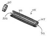
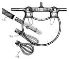
도 1a 및 도 1b는 추체간 유합 장치 및 시스템의 일 실시예의 측면도이다.
도 1c는 반경방향으로 수축되고 축방향으로 신장되는 구조에서 반경방향으로 팽창되고 축방향으로 단축되는 구조로 이행되는 추체간 장치의 일 실시예를 도시한다.
도 2a는 추체간 유합 장치 및 시스템의 일 실시예의 분해 단면도이다.
도 2b는 추체간 유합 장치 및 시스템의 일 실시예의 단면도이다.
도 2c는 C-C 원을 따라서 취한 도 2b의 확대 도시도이다.
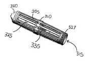
도 3a 내지 도 3c는 반경방향으로 수축되고 축방향으로 신장된 구조에 있는 추체간 장치의 일 실시예의 사시도, 정면도 및 측면도이다.
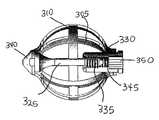
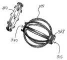
도 4a 내지 도 4c는 반경방향으로 팽창되고 축방향으로 단축된 구조에 있는 도 3a 내지 도 3c의 추체간 장치의 사시도, 정면도 및 측면도이다.
도 5a는 연계 요소 및 로킹 단부 캡의 일 실시예의 사시도이다.
도 5b는 추체간 장치 내에 배치된 연계 요소 및 로킹 단부 캡의 사시도이다.
도 5c는 반경방향으로 팽창되고 인장 로크된 구조에 있는 도 5b의 추체간 장치의 사시도이다.
도 5d는 도 5c의 추체간 장치의 부분 단면도이다.
도 6a는 반경방향으로 수축된 구조에 있는 추체간 장치의 다른 실시예의 분해 사시도이다.
도 6b는 반경방향으로 수축된 구조에 있는 도 6a의 추체간 장치의 사시도이다.
도 6c는 반경방향으로 팽창된 구조에 있는 도 6a의 추체간 장치의 분해 사시도이다.
도 6d는 반경방향으로 팽창된 구조에 있는 도 6a의 추체간 장치의 사시도이다.
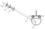
도 7은 반경방향으로 수축되고 축방향으로 신장된 구조에서 반경방향으로 팽창되고 축방향으로 단축된 구조로 이행되는 추체간 장치의 다른 실시예의 도시도이다.
도 8은 인장되고 골 이식 재료로 충전되는, 반경방향으로 팽창되고 축방향으로 단축된 구조에 있는 추체간 장치의 다른 실시예의 도시도이다.
도 9a 내지 도 9c는 추체간 유합 장치 및 시스템의 일 실시예의 예시적인 사용 방법의 도시도이다.1A and 1B are side views of one embodiment of an interbody fusion device and system.
FIG. 1C shows one embodiment of the intervertebral device shifting from a radially contracted and axially elongated structure to a radially expanded and axially shortened structure.
2A is an exploded cross-sectional view of one embodiment of an interbody fusion device and system.
2B is a cross-sectional view of one embodiment of an interbody fusion device and system.
FIG. 2C is an enlarged view of FIG. 2B taken along the circle of CC. FIG.
3A-3C are perspective, front and side views of one embodiment of an interbody device in a radially contracted and axially extended structure.
4A-4C are perspective, front and side views of the interbody device of FIGS. 3A-3C in a radially expanded and axially shortened structure.
5A is a perspective view of one embodiment of the linkage element and the locking end cap.
5B is a perspective view of the locking element and the locking element disposed in the interbody device.
FIG. 5C is a perspective view of the interbody device of FIG. 5B in a radially expanded and tension locked structure. FIG.
5D is a partial cross-sectional view of the interbody device of FIG. 5C.
6A is an exploded perspective view of another embodiment of an interbody device in a radially retracted structure.
6B is a perspective view of the interbody device of FIG. 6A in a radially retracted structure.
6C is an exploded perspective view of the interbody device of FIG. 6A in a radially inflated structure;
6D is a perspective view of the interbody device of FIG. 6A in a radially inflated structure.
FIG. 7 is an illustration of another embodiment of an interbody device shifting from a radially contracted and axially elongated structure to a radially expanded and axially shortened structure.
8 is an illustration of another embodiment of an interbody device in a radially expanded and axially shortened structure that is tensioned and filled with bone graft material.
9A-9C are illustrations of an exemplary method of use of one embodiment of an intervertebral fusion device and system.
개시된 것은 골 구조물을 안정화 및 유합시키도록 구성된 추체간 시스템이다. 본 명세서에 기재된 장치 및 유합 시스템은 최소-침습성 추체간 유합술 용으로 설계되며, 예를 들어 다양한 최소-침습성 접근 채널 또는 소형 접근 포트를 통해서 추간판 공간으로 해제가능하게 전개될 수 있다. 본 명세서에 기재된 장치 및 유합 시스템은 다양한 외과적 적용을 위해 사용될 수 있다.Disclosed is an intervertebral system configured to stabilize and fuse a bone structure. The devices and fusion systems described herein are designed for minimally invasive interbody fusion and can be releasably deployed into the intervertebral space through, for example, various minimally invasive access channels or small access ports. The devices and fusion systems described herein can be used for a variety of surgical applications.
본 명세서에 기재된 추체간 장치는, 외부 쉬쓰 등에 의해 투입 이전에 낮은 프로파일로 능동 절첩되고 이후 골 구조물 사이로의 삽입 및 외부 압축력의 제거 시에는 높은 프로파일로 이완 또는 팽창될 수 있도록 자기-팽창성일 수 있다. 초기 절첩된 구조는 이하에 보다 상세히 설명되는 다양한 방식으로 달성될 수 있는 바, 예를 들면 추체간 장치가 낮은 프로파일로 압축 또는 억제되도록 한정(confining) 슬리브 또는 쉬쓰 또는 억제 링을 사용하여 추체간 장치를 투입함으로써 달성될 수 있다. 타겟 위치에 도입되면, 한정 슬리브 또는 링과 같은 억제 요소는 추체간 장치가 그 체적 확대된 형태를 취할 수 있도록 도입 축을 따라서 후퇴될 수 있다. 본 명세서에 기재된 추체간 장치의 체적 확대된 형태는 외부 치수가 반경방향으로 팽창됨에 따라 축방향 길이가 단축되는 것을 특징으로 한다. 역으로, 본 명세서에 기재된 추체간 장치는 반경방향 압축 시에 축방향으로 길어질 수 있다. 체적 증가는 "결정적인(defining)" 둘레의 배좌(conformational) 변화의 결과이며, 탄성중합적 팽창의 결과가 아니다. 장치를 팽창시키기 위해 장치의 내부를 다른 재료로 충전할 필요가 없음을 알아야 한다. 또한 본 명세서에 기재된 추체간 장치가 인접하는 골면(bone surfaces)을 반드시 변위, 푸시 또는 감소시키지는 않는다는 것도 알아야 한다.The intervertebral device described herein can be self-expansive so that it can be actively folded to a low profile prior to introduction by external sheaths or the like and then relaxed or expanded to a high profile upon insertion between bone structures and removal of external compressive forces. . The initial folded structure can be achieved in a variety of ways, described in more detail below, for example an intervertebral device using a confining sleeve or sheath or restraining ring such that the intervertebral device is compressed or restrained to a low profile. Can be achieved by Once introduced in the target position, the restraining element, such as a confinement sleeve or ring, can be retracted along the introduction axis such that the interbody device can take its enlarged form. The volume enlarged form of the intervertebral device described herein is characterized in that the axial length is shortened as the outer dimension expands radially. Conversely, the intervertebral device described herein can be lengthened axially in radial compression. The volume increase is a result of the conformational change around the "defining" and not the result of the elastomeric expansion. Note that it is not necessary to fill the inside of the device with other materials to inflate the device. It should also be appreciated that the intervertebral device described herein does not necessarily displace, push or reduce adjacent bone surfaces.
이제 도면을 참조하여, 팽창성 추체간 장치 및 유합 시스템의 특정 실시예를 설명할 것이다. 도 1a 및 도 1b는 팽창성 추체간 장치 및 유합 시스템(100)의 일 실시예의 측면도이다. 시스템(100)은 중심 가이드와이어 또는 핀(125)의 원위 단부에 부착되는 추체간 장치(105)를 구비할 수 있다. 추체간 장치(105) 및 핀(125)은 수납 슬리브(110)를 통해서 종방향으로 연장될 수 있다. 수납 슬리브(110)는 예를 들어 삽입을 위한, 낮은 프로파일의 절첩된 상태로 유지되도록(도 1a 참조) 추체간 장치(105)의 외표면에 원주방향 내측 힘을 제공하는 중공 원통형 쉬쓰일 수 있다. 수납 슬리브(110)가 근위 방향(도 1b의 화살표 P)으로 후퇴하면 추체간 장치(105)가 이하에서 보다 상세히 논의되듯이 그 팽창 상태로 자유롭게 이완된다. 추체간 장치(105)는 일반적으로 유지 링 또는 쉬쓰의 압축력이 제거되면 자기-팽창된다. 그러나, 능동 팽창 기술 또는 기구는 장치(105)의 자기-팽창 능력을 보충 또는 대체하기 위해 적용될 수 있음을 알아야 한다.Referring now to the drawings, certain embodiments of the inflatable intervertebral device and fusion system will be described. 1A and 1B are side views of one embodiment of an inflatable interbody device and
제어 슬리브(115)는 또한 수납 슬리브(110)의 내부 관강을 통해서 삽입될 수 있다. 도 2a 내지 도 2c에 가장 잘 도시되어 있듯이, 제어 슬리브(115)는 그 원위 단부 근처에 결합 구역(205)을 갖는다. 제어 슬리브(115)의 결합 구역(205)은 추체간 장치(105)의 근위 단부 근처에 배치되는 상보적 결합부(327)(예를 들면, 도 6a 내지 도 6d 참조)에 가역적으로 결합될 수 있다. 결합 구역(205)은 나사가공될 수 있거나, 또는 당업계에 공지되어 있는 다른 형태의 결합 기구를 가질 수 있다. 제어 슬리브(115)와 핀(125)의 조합은 추체간 장치(105)를 그 좁은 삽입 구조에 유지시키도록 기능할 수 있다. 제어 슬리브(115)와 핀(125)은 또한, 수납 슬리브(110)가 근위 후퇴할 때 추체간 장치(105)의 팽창을 보조하기 위해 조합 사용될 수 있다. 로킹 드라이버(120)는 제어 슬리브(115)의 내부 관강을 통해서 삽입될 수 있다. 이하에서 보다 상세히 논의되듯이, 로킹 드라이버(120)는 그 원위 단부 근처에 결합 기구(210)를 구비할 수 있으며, 이 결합 기구는 로킹 단부 캡(330)(도 2c에 도시됨)에 대한 가역적 결합을 가능하게 한다.The
도 3a 내지 도 3c 및 도 4a 내지 도 4c에 가장 잘 도시되어 있듯이, 추체간 장치(105)는 하나 이상의 가요성 원주방향 제한 밴드(310)에 의해 결합되는 복수의 가요성 아암(305)을 구비할 수 있다. 가요성 아암(305)은 압축력이 해제되면 각각 특정 형상으로 "이완"되도록 자기-팽창성일 수 있다. 예를 들어, 가요성 아암(305)은 추체간 장치(105)가 대체로 회전타원체 형상을 갖는 체적-확대된 형태를 취하도록 반경방향 외측으로 휘어질 수 있다. 내부 장치(105)의 체적-확대된 형태는 일반적으로 외부 치수가 반경방향으로 팽창함에 따라 축방향으로 단축되는 것을 특징으로 한다. 가요성 아암(305)은 장치(105)의 중심축 주위에 비대칭적으로 또는 대칭적으로 배치될 수 있다. 장치(105)는 장치(105)의 중심축 주위에 대칭적으로 또는 비대칭적으로 배치될 수 있는 가요성 아암(305)을 한 쌍, 두 쌍, 세 쌍, 네 쌍, 다섯 쌍 또는 그 이상 가질 수 있다. 장치(105)는 또한 장치(105)의 중심축 주위에 대칭적으로 또는 비대칭적으로 배치되는 가요성 아암(305)을 세 개, 다섯 개, 일곱 개, 아홉 개 또는 그 이상 구비할 수 있다.As best shown in FIGS. 3A-3C and 4A-4C, the
반경방향으로-팽창되는 가요성 아암(305)은 추체간 장치(105)에 다양한 형상의 "결정적인" 둘레를 제공할 수 있다. 팽창된 장치(105)의 형상은 이 장치가 팽창 및/또는 해방되는 작업 공간 또는 구역에 따라 달라질 수 있다. 언급했듯이, 가요성 아암(305)은 팽창된 장치(105)가 회전타원체 형상을 취하도록 장치(105)의 중심축으로부터 반경방향 외측으로 휘어질 수 있다. 가요성 아암(305)은 또한 장치(105)에 보다 만곡된 형상이 주어질 경우 가요성 아암(305)이 특정 각도로 구부러지도록 외측으로 팽창될 수 있다. 팽창된 가요성 아암(305)은 장치(105)에 방추형, 원통형, 튜브형, 장방형, 회전타원체, 우산, 타원형, 쐐기, 원추형, 삼각형, 반월형 또는 대칭적이거나 비대칭적일 수 있는 다른 형상을 제공할 수 있다. 도면에 도시된 실시예는 대체로 방추형의 박벽(thin-walled) 불연속 "케이지(cage)"이다.The radially-expanded
추체간 장치(105)의 표면 형태는 대체로 불연속적이다. 가요성 아암(305)의 각각은 팽창 시에 그 사이에 공간이 형성되도록 폭을 가질 수 있다. 가요성 아암(305)의 폭과 아암(305) 사이 공간의 폭은 변할 수 있다. 일 실시예에서, 가요성 아암의 각각은 약 0.5mm 내지 3mm의 폭을 갖는다. 가요성 아암은 약 0.25mm 내지 1.5mm의 두께를 가질 수 있다. 일 실시예에서, 가요성 아암(305)은 폭을 가지며 각각의 가요성 아암의 일부는 절첩 상태에 있을 때 장치(105)의 전체 직경이 최소화되도록 인접한 가요성 아암(305)과 중첩된다. 가요성 아암(305)은 특정 목적을 위한 특정 강도를 달성하기 위해 더 두껍거나 더 얇게 만들어질 수 있다. 가요성 아암(305)의 각각은 도 1c의 실시예에 도시된 것과 같은 더 넓고 더 편평한 구조를 가질 수 있다. 가요성 아암(305)의 각각은 또한, 도 7과 같은 보다 라운드형인 와이어형 구조를 가질 수 있다. 가요성 아암(305)의 벽 두께와 폭은 균일하거나 불균일할 수 있다. 가요성 아암(305)의 형상은 추체간 장치(105)에 특정한 전체 구조를 제공할 수 있다. 예를 들어, 가요성 아암(305)은 케이지, 거품기, 코일, 스프링, 체인-링크, 짠바구니 또는 "중국식 핑거 트랩(Chinese finger trap)" 구조를 형성할 수 있다.The surface shape of the
제한 밴드(310)는 가요성 아암(305)이 인접하는 추체로부터의 조합된 반경방향 및/또는 접선방향 하중 하에 탈구되지 않도록 팽창된 아암(305)에 안정성을 제공한다. 제한 밴드(310)는 측방향 벽 하중에 저항하기 위한 추체간 장치(105)의 능력을 향상시킬 수 있다. 하나 이상의 제한 밴드(310)가 가요성 아암(305)의 근위 단부와 원위 단부 사이의 다양한 원주방향 위도에 결합될 수 있다. 하나 이상의 제한 밴드(310)는 가요성 아암(305)과 일체적일 수 있거나, 또는 추체간 장치의 외주에 부착되는 별개의 부품일 수 있다(도 6a 내지 도 6d). 후자의 실시예에서, 제한 밴드(310)는 내표면 또는 외표면 상에 가요성 아암(305)의 적어도 일부를 파지하는 하나 이상의 걸쇠(clasp)를 가질 수 있다. 하나 이상의 제한 밴드(310)는 밴드(310)가 장치(105)의 내경 내에 배치되도록 가요성 아암(305)의 내측에 결합될 수 있다. 하나 이상의 제한 밴드(310)는 또한 각각의 가요성 아암(305) 사이에 결합될 수 있다. 제한 밴드(310)는 또한, 아암(305) 사이의 탈구를 방지하기 위해 둘 이상의 가요성 아암(305)을 상호연계시키는 복수의 세그먼트일 수 있다. 제한 밴드(310)는 도 5c의 실시예에 도시된 것과 같은 더 넓고 더 편평한 구조를 가질 수 있다. 제한 밴드(310)는 또한 보다 라운드형인 와이어형 구조를 가질 수 있다. 제한 밴드(310)에 접촉되거나 유합되는 가요성 아암(305)의 부분은, 반경방향으로 수축된 위치에서 제한 밴드(310)의 내측 절첩이 수용되고 장치의 축방향 길이를 따르는 외경이 비교적 일정하도록 감소된 두께 및/또는 특정 폭을 가질 수 있다.
가요성 아암(305)뿐 아니라 원주방향 제한 밴드(310)는 자기-팽창성일 수 있다. 본 명세서에 기재되는 추체간 장치는 방사선투과성 재료[예를 들면, PEEK®, Victrex Corp., 폴리에테르에테르케톤(PolyEtherEtherKetone), 또는 기타 폴리머 재료]를 갖거나 갖지 않는 생체친화적인 형상-기억 합금(예를 들면, 니티놀, 티타늄/니켈 합금, 니티놀 와이어 메시)으로 구성될 수 있다. 추체 장치 내에 방사선불투과성 요소 및 방사선투과성 요소를 사용하는 것은 골간 골 치유의 개선된 방사선 모니터링을 제공하는 한편으로, 향상된 기계적 성능을 제공한다. 또한, 고려되는 것은 신장되거나 연신 상태에 있을 때 그 직경이 감소하도록 한정 원위 벽 및 초기 개방형 근위 단부를 갖는 바이어스 플라이(bias ply) 또는 메쉬 재료(예를 들면, 폴리머 스트랜드, 또는 와이어 스트랜드)로 조성된 벽을 갖는 튜브형 장치이다. 일 실시예에서, 아암(305) 및/또는 제한 밴드(310)는 당업계에 공지되어 있듯이 니티놀을 레이저 절단함으로써 제조된다. 튜브형 장치는 또한 백금, 금, 팔라듐, 레늄, 탄탈, 텅스텐, 몰리브덴, 레늄, 니켈, 코발트, 스테인레스 스틸, 니티놀, 및 그 합금을 포함하는 재료로 제조될 수 있다.The circumferential limiting
수납 슬리브(110)의 후퇴 시에 추체간 장치(105)가 반경방향으로 팽창되면, 추체간 장치(105) 역시 축방향으로 단축된다. 비팽창 구조에서, 아암(305)은 반경방향으로 절첩되어 장치(105)에 근위 개구(315)와 원위 개구(320)를 갖는 대체로 원통형이고 축방향으로 신장된 형상을 제공한다(도 1a, 도 3a 내지 도 3c 및 도 5b 참조). 이 형상은 추체간 장치(105)가 작업 채널을 통해서 골 공극 또는 소개된 추간판 공간에 투입되기 위해 수납 슬리브(110)의 비교적 작은 내경에 끼워질 수 있게 한다. 장치(105)가 비팽창 구조에 있을 때, 제한 밴드(310)는 장치(105)의 내경 내에서 아암(305) 사이에 일련의 대체로 파형(undulating)인 링크를 형성하기 위해 내측으로 좌굴 또는 절첩될 수 있다(도 3b 참조). 제한 밴드(310)가 가요성 아암(305)의 외표면에 결합되면, 제한 밴드(310)는 내경 내에 배치되기 위해 각각의 가요성 아암(305) 사이의 공간을 통해서 내측으로 좌굴될 수 있다. 수납 슬리브(110) 또는 기타 압축 기구의 후퇴 시에, 추체간 장치(105)는 그 팽창된 상태(도 1b, 도 4a 내지 도 4c 및 도 5c)로 이완될 수 있다. 제한 밴드(310)의 사행(serpentine) 링크가 하나 이상의 위도를 따라서 아암(305)을 연결하는 대체로 원주방향의 링을 형성하기 위해 펼쳐지도록 아암(305)은 반경방향 외측으로 팽창하고 추가로 멀어진다.If the
제한 밴드(310)에 추가적으로, 추체간 장치(105)는 다른 안정화 특징을 가질 수 있다. 일 실시예에서, 추체간 장치(105)는 반경방향으로 팽창된 구조에 로크될 수 있다. 반경방향 압축 하중을 견뎌내도록 팽창된 추체간 장치(105)를 보강하는 "활시위(bowstring)" 효과를 제공하기 위해 기계적 커플링이 생성될 수 있다. 도 5a 내지 도 5d에 가장 잘 도시되어 있듯이, 추체간 장치(105)는 연계 요소(325) 및 단부 캡(330)을 구비할 수 있다. 연계 요소(325)는 추체간 장치(105)의 내부를 통해서 근위 개구(315)로부터 원위 개구(320)로 연장될 수 있다. 연계 요소(325)는 인장 밴드, 나사 또는 기타 "활시위"형 요소일 수 있다. 연계 요소(325)는 그 근위 단부 근처에 결합부(335)를 갖고 그 원위 단부 근처에 노즈 피스(nose piece)(340)를 가질 수 있다. 노즈 피스(340)의 원위 단부는 뾰족하거나 총탄-형상 또는 기타 형상을 포함하는 다양한 형상을 가질 수 있다. 단부 캡(330)은 수납 슬리브(110)를 통해서 추체간 장치(105)의 근위 개구(315) 내에 삽입될 수 있다. 단부 캡(330)은, 연계 요소(325)를 거쳐서 추체간 장치(105)의 근위 단부와 원위 단부를 기계적으로 링크시키도록 연계 요소의 결합부(335)에 상보적인 결합부(345)를 그 근위 단부 근처에 가질 수 있다. 연계 요소(325)의 노즈 피스(340)는 그 원위 개구(320)에서 추체간 장치(105)에 부착될 수 있다. 연계 요소(325)의 결합부(335)는 단부 캡(330)의 상보적 결합부(345)와 결합할 수 있다. 연계 요소(325)와 단부 캡(330) 사이의 기계적 결합은 구조적 개선을 제공하며, 추체간 장치(105)의 긴 중심축에 수직한 방향의 측방향 벽 하중 또는 압축 하중(예를 들면, 반경방향 하중)을 견뎌내는 추체간 장치(105)의 능력을 향상시킨다. 이들 하중은 연계 요소(325)에 인장 하중을 유발하여 장치(105)의 근위 단부(315) 및 원위 단부(320)를 고정시킨다.In addition to the limiting
연계 요소(325)의 결합부(335) 및 단부 캡(330)의 결합부(345)는 나사가공된 것으로 도시되어 있지만, 연계 요소(325)와 단부 캡(330) 사이의 다른 결합 기구가 고려됨을 알아야 한다. 단부 캡(330)과 연계 요소(325) 사이의 기계적 결합은 또한 장치(105)의 근위 내지 원위 단부에 더 근접하여 로킹 중에 추체간 장치(105)의 추가적인 반경방향 팽창 및 축방향 단축을 제공하도록 사용될 수도 있다.Although the
도 5d에 가장 잘 도시되어 있듯이, 단부 캡(330)은 원위 결합부(345)에 추가적으로 근위 육각 구역(350)을 구비할 수 있다. 전술했듯이, 로킹 드라이버(120)의 결합 기구(210)(예를 들면, 육각 헤드)는 단부 캡(330)의 상보적 근위 구역(350)에 가역적으로 결합될 수 있다. 결합 기구(210)는 단부 캡(330)의 상보적 육각 구역(350)에 결합되어 단부 캡(330)을 연계 요소(325)의 결합부(335)와 나사결합시킬 수 있다. 로킹 드라이버(120)와 단부 캡(330) 사이의 다른 결합 기구가 고려됨을 알아야 한다.As best shown in FIG. 5D, the
도 7은 거품기형 구조를 갖는 팽창 추체간 장치(705)의 일 실시예를 도시한다. 이 실시예에서, 시스템은 추체간 장치(705)를 투입을 위한 절첩 상태로 유지하기 위해 수납 슬리브(110) 대신에 슬라이드 가능한 유지 링(710)을 사용한다. 투입 배좌에서, 유지 링(710)은 가요성 요소들이 상호 밀접하도록 장치(705)의 원위 단부 근처에 위치한다. 장치(705)를 팽창시키기 위해, 유지 링(710)은 가요성 요소들이 반경방향 외측으로 휘어질 수 있도록 화살표 방향으로 근접 이동될 수 있다. 유지 링(710)을 이동시키는 기구는 당업계에 공지되어 있듯이 달라질 수 있다.7 illustrates one embodiment of an expanding
"이완" 팽창된 상태에서, 본 명세서에 기재된 추체간 장치의 외표면의 부분은 일반적으로 준비된 단부판에 근접, 접촉 및/또는 합치된다. 반경방향으로 팽창되면, 추체간 유합(즉, 꽉찬 추체간 케이지 기술)을 그 최종 형태로 제공하기 위해 재료가 본 명세서에 기재된 추체간 장치의 불연속 벽의 공극 내에, 잠재적으로는 공극을 통해서 도입될 수 있다. 예시적인 재료는 골 성장 재료, 골 이식 재료, 골 공극 충전재, 해면질 또는 피질 골이식재, 해면질 또는 피질 골편, 골전도성 재료, 골증식성 재료, 및/또는 골유도성 재료, 골 형태형성 시토카인, BMP-2, 골재료에 침지된 콜라겐 스폰지, 또는 BMP-2 침지된 콜라겐 스폰지를 포함한다.In the "relaxed" expanded state, portions of the outer surface of the intervertebral device described herein are generally in close contact, contact and / or mating with the prepared end plates. Once radially expanded, material may be introduced into the pores of the discontinuous walls of the intervertebral device described herein, potentially through the pores, to provide the intervertebral union (ie, full intervertebral cage technology) in its final form. Can be. Exemplary materials include bone growth materials, bone graft materials, bone void fillers, spongy or cortical bone grafts, spongy or cortical bone fragments, osteoconductive materials, osteoproliferative materials, and / or osteoinductive materials, bone morphogenic cytokines, BMP- 2, collagen sponges immersed in bone material, or collagen sponges BMP-2 immersed.
도 8에 도시하듯이, 충전재(805)는 수납 슬리브(110) 또는 제어 슬리브(115)와 같은 투입 캐뉼러를 통해서, 및 부분적으로 이제 "이완된" 장치(105)의 공극을 통해서, 팽창된 추체간 장치(105)의 내부 체적에 투입될 수 있다. 연계 요소(325)와 단부 캡(330)의 연관 또는 결합은 추체간 장치(105)의 원위 및/또는 근위 단부(들)를 "밀봉"시키고, 골유도성 및/또는 골증식성 재료와 같은 삽입된 재료가 추체간 유합 장치의 내부 챔버의 전체 범위 내에서 후속 이동하는 것을 방지하거나 최소화한다. 충전재(805)는 도입 축을 따라서 투입 캐뉼러 내로부터 팽창된 추체간 장치(105)의 내부로 투입될 수 있다. 이는 장치(105)의 외주에 바로 인접한 영역으로부터 이완된 장치(105) 내로 관통하는 골 성장을 제공한다. 추가로, 재료를 반경방향으로 변위시키기 위해 변위 요소가 삽입될 수 있으며, 그 결과 추체간 장치의 팽창된 주위 요소 내에 충전재가 관통 분포된다. 충전재(805)는 일반적으로 추체간 장치(105)를 변형시키거나 반경방향으로 팽창시키기 위해 사용되지 않거나 또는 보충적인 구조적 지지를 반드시 제공하지도 않음을 알아야 한다.As shown in FIG. 8, the
추체간 장치(105)가 팽창되고, 경우에 따라 소정의 합성물 또는 재료로 충전되며, 로크되면, 이 추체간 장치는 해제가능하게 전개될 수 있다. 로킹 드라이버(120)는 근위로 후퇴될 수 있다. 제어 슬리브(115)의 원위 단부 근처의 결합 구역(205)은 추체간 장치(105)의 상보적 근위 결합부(327)로부터 나사풀림, 회전 및/또는 견인되거나 결합해제될 수 있다. 결합 구역은 간단한 나사 형태, 총검 스타일 로킹 기구, 견인 로크(pull lock) 또는 기타 간섭 끼움 또는 마찰 로크일 수 있다. 인접하는 단부 판들은 장치(105)가 투입 시스템의 부품으로부터 결합 해제될 수 있도록 장치(105)를 적소에 결합 및 유지시킬 수 있다. 핀(125)은 또한 투입 시스템의 부품의 해제 및 전개 중에 추체간 장치(105)를 유지하거나, 간섭 끼움 또는 마찰 로크에 의존하는 간단한 견인 로크에 대항하도록 기능할 수 있다. 장치(105)의 근위 단부로부터 결합해제되면, 수납 슬리브(110), 제어 슬리브(115) 및 핀(125)은 근위로 후퇴되어 추체간 장치(105)를 추간판 공간 내에 전개시킬 수 있다.When the
경우에 따라, 추체간 장치(105)는 그 팽창전 구조로 환원되어 제거될 수 있다. 단부 캡(330)은 연계 요소(325)와의 기계적 연계로부터 제거될 수 있다. 이후 핀(125) 또는 기타 축방향으로-전개된 요소는 전진되어, 장치(105)의 근위 단부가 억제되는 동안 제어 슬리브(115) 등에 의해 연계 요소(325)를 원위 방향으로 변위시킬 수 있다. 추체간 장치(105)는 이후 수납 슬리브(110) 내로 근위 후퇴 복귀할 수 있도록 축방향으로 신장되고 반경방향으로 수축될 수 있다.In some cases, the
사용 방법How to use
전술했듯이, 본 명세서에 기재되는 추체간 장치 및 유합 시스템은 최소-침습 추체간 유합술 용으로 설계되며, 다양한 최소-침습 접근 채널(TLIF, ITLIF™, ITSLIF, EXLIF™, DLIF™, ALIF, PLIF 등)을 통해서 전개될 수 있다.As noted above, the intervertebral device and fusion system described herein are designed for minimally invasive interbody fusion and include a variety of minimally invasive access channels (TLIF, ITLIF ™, ITSLIF, EXLIF ™, DLIF ™, ALIF, PLIF, etc.). Can be deployed through
본 명세서에 기재되는 추체간 장치는, 초기의 절첩되거나 근접한 조건에서 골간 공간이 존재하고 치유적 개입이 골간 공간(예를 들면, 퇴행성 추간판 공간)을 후속 안정화에 의해 분산시키는 다양한 외과적 적용을 위해 사용될 수 있다. 추체간 장치는 소개된 추간판 공간 내로 전개될 수 있으며, 예를 들면 디스크 재료의 제거와 단부판의 박리가 이어진다. 본 명세서에 기재된 추체간 장치 및 유합 시스템의 다른 잠재적 적용은 골 낭종 또는 정복 골절에서 발생할 수 있는 것과 같은 기존의 또는 발생된 골 결손의 치료를 위한 것이다. 이 적용뿐 아니라 다른 적용이 투입 캐뉼러를 통한 경피적 방법을 거쳐서 전개될 수 있다.The intervertebral device described herein is intended for a variety of surgical applications where interstitial spaces are present in initial folded or proximal conditions and healing interventions disperse the interstitial spaces (eg, degenerative intervertebral disc spaces) by subsequent stabilization. Can be used. The intervertebral device can be deployed into the intervertebral disc space introduced, for example, followed by removal of the disc material and exfoliation of the end plate. Another potential application of the intervertebral device and fusion system described herein is for the treatment of existing or developed bone defects, such as those that may occur in bone cysts or reduction fractures. This application as well as other applications can be developed via the percutaneous method via the input cannula.
이제 상기 시스템을 사용하는 예시적인 방법을 설명한다. 치료할 디스크 공간에 대한 접근을 제공하기 위해 환자에게 적어도 하나의 경로가 형성될 수 있다. 적어도 하나의 경로를 형성하기 위해 다양한 방법 및 장치가 사용될 수 있다. 디스크 공간은 부분적으로-비워진 디스크 공간과 같은 준비된 디스크 공간일 수 있다. 일 실시예에서는, 한 쌍의 골내 경척추경 경로가 형성될 수 있으며, 각각의 경로는 디스크 공간 내로의 입구를 제공한다. 일 실시예에서는, 디스크의 중간 시상 평면의 양쪽에 접근 경로가 형성된다. 경로는 예를 들어 그 각각의 전체가 본 명세서에 원용되는 미국 특허공개 제2007-0162044호, 제2009-0312764호 및 2010년 5월 11일자로 출원된 미국 특허출원 제12/778,057호에 기재된 방법 및 장치에 따라 형성될 수 있다. 이들 도면은 척추 내의 해부학적 랜드마크, 및 추체를 통한 추간판 공간에의 접근을 개략 도시한다. 당업자는 실제 해부구조가 도면에 도시되지 않은 해부학적 상세를 포함하는 것을 알 것이다.An exemplary method of using the system will now be described. At least one path may be formed in the patient to provide access to the disk space to be treated. Various methods and devices may be used to form at least one path. The disk space may be prepared disk space, such as partially-empty disk space. In one embodiment, a pair of intraosseous pedicle paths can be formed, each providing an entry into the disk space. In one embodiment, access paths are formed on both sides of the intermediate sagittal plane of the disc. The route is for example the method described in U.S. Patent Publication Nos. 2007-0162044, 2009-0312764, and US Patent Application No. 12 / 778,057, filed May 11, 2010, the entirety of which is incorporated herein by reference. And according to the device. These figures schematically illustrate the anatomical landmarks in the spine, and access to the intervertebral space through the vertebrae. Those skilled in the art will appreciate that the actual anatomy includes anatomical details not shown in the figures.
경로가 형성되면, 추체간 장치(105)는 골 공극에 삽입하기에 적합한 반경방향으로 수축되고 축방향으로 신장된 구조를 달성하기 위해 시스템(100)의 수납 슬리브(110) 내에서 능동적으로 압축될 수 있다. 도 9a는 디스크 공간에 대해 골내 경척추경 경로에 배치되는 추체간 장치(105)의 일 실시예를 도시한다. 적절한 위치에 있으면, 핀(125)과 제어 슬리브(115)는 수납 슬리브(110)가 근위 방향(도 9b에서 화살표 P)으로 후퇴할 때 추체간 장치(105)의 위치를 안정화시키기 위해 약간 원위 방향으로 압박될 수 있다. 추체간 장치(105)는 수납 슬리브(110)의 원위 단부를 통해서 노출되며, 반경방향으로 팽창되고 축방향으로 단축된 구조로 이완될 수 있다. 가요성 아암(305)은 외측으로 이완될 수 있으며, 파형 제한 밴드(310)는 대체로 원주방향 링으로 펼쳐져서 아암(305)의 탈구에 대한 안정성을 제공할 수 있다.Once the path is formed, the
추체간 장치(105)의 내부를 통해서 연장되는 연계 요소(325)의 노즈 총탄(340)(도 9c 참조)은 추체간 장치(105)의 원위 개구(320)에 결합될 수 있다. 로킹 단부 캡(330)은 로킹 드라이버(120)를 사용하여 제어 슬리브(115)를 통해서 삽입될 수 있다. 로킹 드라이버(120)는 로킹 드라이버(120)의 육각 헤드가 단부 캡(330)의 근위 구역에서 육각 구역과 결합되도록 회전될 수 있다. 단부 캡(330)이 로킹 드라이버(120)에 의해 회전됨에 따라, 단부 캡(330)의 결합부(345)는 연계 요소(325)의 상보적 결합부(335)에 결합된다. 연계 요소(325)와 단부 캡(330) 사이의 기계적 결합은 구조적 개선을 제공하며, 추체간 장치(105)의 긴 중심축에 수직한 방향의 측방향 벽 하중 또는 압축 하중을 견뎌내는 추체간 장치(105)의 능력을 향상시킨다. 이들 하중은 연계 요소(325) 및 그 내부의 단부 캡(330)에 인장 하중을 유발하여 추체간 장치(105)의 근위 단부 및 원위 단부를 축방향으로 단축된 구조에 로크시킨다.The nose bullet 340 (see FIG. 9C) of the
추체간 요소(105)에 대한 연계 요소(325) 및 단부 캡(330)의 결합은 또한, 골 성장 재료 또는 다른 형태의 치료용 충전재가 추체간 장치(105)의 공극 또는 내부에 주입될 수 있도록 근위 및 원위 개구(315, 320)를 밀봉한다. 추체간 장치(105)가 인장, 로크되고, 경우에 따라 소정의 합성물 또는 재료로 충전되면, 이 추체간 장치는 제어 슬리브(115)의 원위 단부를 추체간 장치(105)의 근위 단부로부터 나사해제시키는 등에 의해 해제될 수 있으며, 골 공극 또는 소개된 추간판 공간과 같은 타겟 치료 장소 내에서 전개될 수 있다(도 9c 참조).The coupling of the
제조 방법Manufacturing method
본 명세서에 기재된 척추 안정화 장치는 당업계에 공지된 방법에 따라 제조될 수 있다. 일 실시예에서, 상기 장치의 제조는 내부 통로와 축방향 길이를 갖는 튜브형 요소를 제공하는 단계를 포함한다. 튜브형 요소는 단부가 함께 결합되어 튜브를 형성하는 튜브형 재료 또는 재료 시트의 단일 모놀리스(monolith)일 수 있다. 튜브형 요소는 형상 기억 재료 또는 당업계에 공지되어 있는 다른 재료로 제조될 수 있다. 튜브형 요소의 종축 또는 축방향 길이에 평행한 절단선을 사용하여 튜브형 요소의 부분을 제거하기 위해 레이저 시스템이 사용될 수 있다. 예를 들어, 당업계에 공지되어 있는 레이저 증발 또는 가공 기술이 사용될 수 있다. 절단선은 일부가 제거되도록 그리고 튜브형 요소를 관통하는 개구가 형성되도록 튜브형 요소의 전체 두께를 통해서 연장될 수 있다. 이는 제1 두께를 갖는 내부 통로를 둘러싸는 복수의 세장형, 축방향으로 정렬된 가요성 아암을 생성하고 아암 사이에 복수의 간격을 생성한다. 생성되는 아암의 패턴은 전술한 바와 같이 변경될 수 있다.Spinal stabilization devices described herein can be prepared according to methods known in the art. In one embodiment, the manufacture of the device comprises providing a tubular element having an inner passageway and an axial length. The tubular element may be a single monolith of tubular material or sheet of material, the ends of which are joined together to form a tube. The tubular element can be made of shape memory material or other materials known in the art. A laser system can be used to remove portions of the tubular element using cut lines parallel to the longitudinal axis or axial length of the tubular element. For example, laser evaporation or processing techniques known in the art can be used. The cut line may extend through the entire thickness of the tubular element such that a portion is removed and an opening is formed through the tubular element. This creates a plurality of elongate, axially aligned flexible arms surrounding the inner passageway having the first thickness and a plurality of gaps between the arms. The pattern of the generated arms can be changed as described above.
레이저 시스템은 또한 튜브형 요소의 긴 축 또는 축방향 길이를 횡단하는 절단선을 사용하여 아암으로부터 단수 또는 복수의 재료 층을 제거하기 위해 사용될 수 있다. 이 실시예에서, 절단선 또는 분할선은 튜브형 요소의 벽의 전체 반경방향 두께 미만을 통해서 연장된다. 이는 단수 또는 복수의 재료 층을 제거하며, 제1 두께보다 얇은 제2 두께를 갖는 아암 부위를 생성한다.Laser systems can also be used to remove singular or plural layers of material from the arm using cutting lines that traverse the long axis or axial length of the tubular element. In this embodiment, the cut or dividing line extends through less than the entire radial thickness of the wall of the tubular element. This removes the singular or plural material layers, creating an arm portion having a second thickness that is thinner than the first thickness.
튜브형 요소는 전술했듯이 니티놀, 티타늄/니켈 합금 또는 폴리머 재료와 같은 형상 기억 재료로 제조될 수 있다. 튜브형 요소의 형상 기억은 반경방향으로 팽창되고 축방향으로 단축된 구조에 있을 때 성형 및 열-설정될(heat-set) 수 있다. 일 실시예에서, 장치는 니티놀 재료이며, 대체로 체온에서 초탄성 특성을 갖는다. 튜브형 요소는 이후, 반경방향으로 수축되고 축방향으로 신장된 구조로 압축 및 냉각될 수 있다. 따라서, 튜브형 요소의 아암은 구속력이 해방되면 반경방향으로 팽창되고 축방향으로 단축된 안정화 구조로 자기-팽창될 수 있다.The tubular element may be made of a shape memory material such as nitinol, titanium / nickel alloy or polymer material as described above. The shape memory of the tubular element can be shaped and heat-set when in a radially expanded and axially shortened structure. In one embodiment, the device is a nitinol material and generally has superelastic properties at body temperature. The tubular element can then be compressed and cooled into a radially contracted and axially elongated structure. Thus, the arm of the tubular element can be self-expanded with a stabilizing structure that is radially expanded and axially shortened when the restraining force is released.
아암 탈구를 방지하기 위한 가요성 제한 밴드는 제2 두께를 갖는 아암 부위에 원주방향으로 결합될 수 있다. 밴드는 아암이 팽창 구조에 있을 때 아암에 용접될 수 있다. 대안적으로, 제한 밴드는 세장형 아암 사이에서 연장되는 튜브형 부재의 종축을 횡단하는 브릿지연결 요소 및 튜브형 부재의 종축과 정렬되는 세장형 아암의 패턴을 형성하는 튜브형 요소의 전체 두께를 통해서 진행되는 절단이 이루어지도록 레이저 시스템으로 절단선을 만들어서 가요성 아암이 생성됨에 따라 생성될 수 있다. 가요성 아암의 이 불균일한 벽 두께는 반경방향으로 수축된 구조에 있을 때 제한 밴드와 접촉하거나 제한 밴드에 유합되는 영역이 비교적 일정한 외경을 갖게 할 수 있고 주위 제한 밴드의 내측 절첩을 수용할 수 있게 한다.A flexible confinement band to prevent arm dislocation can be circumferentially coupled to the arm site having a second thickness. The band can be welded to the arm when the arm is in the inflation structure. Alternatively, the restricting band is cut through a bridge connecting element traversing the longitudinal axis of the tubular member extending between the elongate arms and the entire thickness of the tubular element forming a pattern of elongate arms aligned with the longitudinal axis of the tubular member. This can be done by making a cut line with the laser system as the flexible arm is created. This non-uniform wall thickness of the flexible arm allows the area to be in contact with or union with the limiting band when in a radially contracted structure to have a relatively constant outer diameter and to accommodate the inner fold of the surrounding limiting band. do.
본 명세서는 여러가지 사양을 포함하지만, 이것들은 청구되거나 청구될 수 있는 본 발명의 범위를 제한하는 것으로 간주되지 않아야 하며, 특정 실시예 고유의 특징을 설명하는 것으로 간주되어야 한다. 복수의 개별 실시예와 관련하여 본 명세서에 기재된 특정한 특징은 또한 단일 실시예에서 조합하여 실시될 수도 있다. 역으로, 단일 실시예와 관련하여 기재되는 다양한 특징은 또한 복수의 실시예에서 개별적으로 실시되거나 임의의 적합한 준조합으로 실시될 수 있다. 더욱이, 특징이 특정 조합으로 작용하는 것으로 전술될 수 있고 심지어 초기에는 그렇게 청구될 수 있지만, 청구된 조합으로부터의 하나 이상의 특징은 일부 경우에 상기 조합으로부터 삭제될 수 있으며, 청구된 조합은 준조합 또는 준조합의 변형에 관한 것일 수 있다. 마찬가지로, 작동이 도면에서 특정 순서로 도시되었지만, 이것을 소정 결과를 달성하기 위해서 이러한 작동이 도시된 특정 순서로 또는 순차적인 순서로 수행될 필요가 있다거나 모든 도시된 작동이 수행될 필요가 있는 것으로 이해해서는 안된다. 몇 가지 예와 실시예만을 개시하였다. 이 개시된 것에 기초하여, 기재된 예와 실시예 및 기타 실시예에 대한 변형, 수정 및 개선이 이루어질 수 있다.While the specification includes several specifications, these should not be considered as limiting the scope of the invention as claimed or claimed, and should be considered as describing features inherent in particular embodiments. Certain features that are described in this specification in the context of a plurality of separate embodiments can also be implemented in combination in a single embodiment. Conversely, various features described in connection with a single embodiment can also be implemented individually in a plurality of embodiments or in any suitable subcombination. Moreover, while a feature may be described above as acting in a particular combination and may even be claimed initially, one or more features from the claimed combination may in some cases be deleted from the combination, and the claimed combination may be sub-combination or quasi-combination. It may be related to a variation of the combination. Likewise, although the operations are shown in a particular order in the figures, it is understood that these operations need to be performed in the specific order shown or in sequential order or all illustrated operations need to be performed to achieve a desired result. Should not. Only a few examples and examples are disclosed. Based on this disclosure, variations, modifications, and improvements to the described examples, embodiments, and other embodiments may be made.
Claims (50)
Translated fromKorean원위 단부 부분과 근위 단부 부분을 갖고, 원위 단부 부분과 근위 단부 부분 사이에 내부 체적을 형성하는 복수의 세장형 아암;
상기 복수의 세장형 아암에 원주방향으로 결합되는 제한 밴드; 및
상기 내부 체적 내에 배치되는 인장 요소를 포함하며,
상기 복수의 세장형 아암은, 반경방향으로 수축되고 축방향으로 신장되는 강제된 투입 구조에서, 반경방향으로 팽창되고 축방향으로 단축되며 추간판 공간 내에서 해방되도록 구성되는 이완된 전개 구조로 수동적으로 이행되는 척추 안정화 장치.Spine stabilization device,
A plurality of elongate arms having a distal end portion and a proximal end portion and defining an interior volume between the distal end portion and the proximal end portion;
A restriction band circumferentially coupled to the plurality of elongate arms; And
A tensioning element disposed within said interior volume,
The plurality of elongate arms are passively transitioned from a forced input structure that is radially retracted and axially elongated to a relaxed deployment structure that is configured to be radially expanded, shortened axially and released within the intervertebral disc space. Spinal stabilization device.
원위 단부 부분과 근위 단부 부분을 갖는 복수의 세장형 아암을 구비하는 추체간 장치로서, 상기 세장형 아암은 추체간 장치의 원위 단부 부분과 근위 단부 부분 사이에 내부 체적을 형성하고, 상기 복수의 세장형 아암 중 하나 이상에는 적어도 하나의 제한 밴드가 원주방향으로 결합되며, 상기 추체간 장치는 반경방향으로 수축되고 축방향으로 신장되는 강제된 투입 구조에서 반경방향으로 팽창되고 축방향으로 단축되는 이완된 전개 구조로 이행될 수 있는 추체간 장치;
상기 내부 체적 내에 배치되며 연계 막대 및 로킹 단부 캡을 구비하는 인장 요소; 및
상기 추체간 장치에 결합하도록 구성되는 캐뉼러 조립체로서, 투입 구조의 추체간 장치를 수납하도록 크기 형성된 내강을 갖는 슬라이드 가능한 수납 슬리브, 추체간 장치의 근위 단부 부분에 결합되는 원위 결합 요소를 갖는 제어 슬리브, 및 로킹 드라이버 요소를 구비하는 캐뉼러 조립체를 포함하며,
상기 추체간 장치는 수납 슬리브가 근위로 후퇴할 때 투입 구조에서 전개 구조로 이행되는 추체간 유합 시스템.Interbody fusion system,
An intervertebral device having a plurality of elongate arms having a distal end portion and a proximal end portion, the elongate arms forming an internal volume between the distal end portion and the proximal end portion of the intervertebral device, At least one restriction band is circumferentially coupled to at least one of the elongate arms, the interbody device being radially expanded and axially relaxed in a forced input structure that is radially retracted and axially elongated. Interbody device that can be implemented into a deployment structure;
A tensioning element disposed within said interior volume and having a linkage rod and a locking end cap; And
A cannula assembly configured to engage the interbody device, the cannula assembly comprising: a slidable receiving sleeve having a lumen sized to receive an interbody device of an input structure; a control sleeve having a distal coupling element coupled to a proximal end portion of the interbody device And a cannula assembly having a locking driver element,
The intervertebral fusion system transitions from the input structure to the deployment structure when the receiving sleeve retracts proximally.
내부 통로와 축방향 길이를 갖고 형상 기억 재료로 제조되는 튜브형 요소를 제공하는 단계;
레이저 시스템을 제공하는 단계;
상기 튜브형 요소의 축방향 길이에 평행한 절단선을 사용하여 레이저 시스템으로 튜브형 요소의 부분을 제거하는 단계로서, 상기 부분의 제거는 상기 요소를 관통하는 개구를 형성하며, 제1 두께를 갖는 내부 통로를 둘러싸는 복수의 세장형 축방향-정렬된 가요성 아암과 상기 아암들 사이의 복수의 공간을 생성하는, 단계;
상기 튜브형 요소의 축방향 길이를 횡단하는 절단선을 사용하여 레이저 시스템으로 아암으로부터 재료의 층을 제거하는 단계로서, 상기 재료 층의 제거는 제1 두께보다 얇은 제2 두께를 갖는 아암 부위를 생성하는, 단계;
상기 튜브형 요소의 형상 기억을 반경방향으로 팽창되고 축방향으로 단축된 구조로 설정하는 단계;
가요성 제한 밴드를 복수의 아암의 원주방향으로 상기 제2 두께를 갖는 아암 부위에 결합하는 단계; 및
상기 튜브형 요소를 반경방향으로 수축되고 축방향으로 신장된 구조로 압축하는 단계를 포함하는 척추 안정화 장치 제조 방법.Method of manufacturing a spinal stabilization device,
Providing a tubular element having an inner passageway and an axial length and made of a shape memory material;
Providing a laser system;
Removing a portion of the tubular element with a laser system using a cutting line parallel to the axial length of the tubular element, the removal of the portion forming an opening through the element, the inner passage having a first thickness Creating a plurality of elongate axially-aligned flexible arms surrounding a plurality of spaces between the arms;
Removing a layer of material from the arm with a laser system using a cutting line traversing the axial length of the tubular element, wherein the removal of the material layer produces an arm portion having a second thickness that is thinner than the first thickness. , step;
Setting the shape memory of the tubular element in a radially expanded and axially shortened structure;
Coupling a flexible confinement band to an arm portion having the second thickness in the circumferential direction of a plurality of arms; And
Compressing the tubular element into a radially contracted and axially elongated structure.
Applications Claiming Priority (2)
| Application Number | Priority Date | Filing Date | Title |
|---|---|---|---|
| US21800909P | 2009-06-17 | 2009-06-17 | |
| US61/218,009 | 2009-06-17 |
Publications (1)
| Publication Number | Publication Date |
|---|---|
| KR20120047231Atrue KR20120047231A (en) | 2012-05-11 |
Family
ID=42799826
Family Applications (1)
| Application Number | Title | Priority Date | Filing Date |
|---|---|---|---|
| KR1020127001209AWithdrawnKR20120047231A (en) | 2009-06-17 | 2010-06-09 | Expanding intervertebral device and methods of use |
Country Status (7)
| Country | Link |
|---|---|
| US (1) | US8529628B2 (en) |
| EP (1) | EP2442741B1 (en) |
| KR (1) | KR20120047231A (en) |
| CN (1) | CN102510742B (en) |
| CA (1) | CA2765526A1 (en) |
| ES (1) | ES2527819T3 (en) |
| WO (1) | WO2010147829A1 (en) |
Families Citing this family (96)
| Publication number | Priority date | Publication date | Assignee | Title |
|---|---|---|---|---|
| DE10154163A1 (en) | 2001-11-03 | 2003-05-22 | Advanced Med Tech | Device for straightening and stabilizing the spine |
| US6793678B2 (en) | 2002-06-27 | 2004-09-21 | Depuy Acromed, Inc. | Prosthetic intervertebral motion disc having dampening |
| AU2004212942A1 (en) | 2003-02-14 | 2004-09-02 | Depuy Spine, Inc. | In-situ formed intervertebral fusion device |
| US20040267367A1 (en) | 2003-06-30 | 2004-12-30 | Depuy Acromed, Inc | Intervertebral implant with conformable endplate |
| US8636802B2 (en) | 2004-03-06 | 2014-01-28 | DePuy Synthes Products, LLC | Dynamized interspinal implant |
| US7988735B2 (en)* | 2005-06-15 | 2011-08-02 | Matthew Yurek | Mechanical apparatus and method for delivering materials into the inter-vertebral body space for nucleus replacement |
| WO2008070863A2 (en) | 2006-12-07 | 2008-06-12 | Interventional Spine, Inc. | Intervertebral implant |
| US8900307B2 (en) | 2007-06-26 | 2014-12-02 | DePuy Synthes Products, LLC | Highly lordosed fusion cage |
| CA2781407A1 (en) | 2008-01-14 | 2009-07-23 | Michael P. Brenzel | Apparatus and methods for fracture repair |
| EP2237748B1 (en) | 2008-01-17 | 2012-09-05 | Synthes GmbH | An expandable intervertebral implant |
| WO2009114523A1 (en) | 2008-03-14 | 2009-09-17 | Synthes Usa, Llc | Nested expandable sleeve implant |
| US8936641B2 (en) | 2008-04-05 | 2015-01-20 | DePuy Synthes Products, LLC | Expandable intervertebral implant |
| US7976578B2 (en)* | 2008-06-04 | 2011-07-12 | James Marvel | Buffer for a human joint and method of arthroscopically inserting |
| US9526620B2 (en) | 2009-03-30 | 2016-12-27 | DePuy Synthes Products, Inc. | Zero profile spinal fusion cage |
| KR101687435B1 (en) | 2009-07-06 | 2016-12-19 | 신세스 게엠바하 | Expandable fixation assemblies |
| US9393129B2 (en) | 2009-12-10 | 2016-07-19 | DePuy Synthes Products, Inc. | Bellows-like expandable interbody fusion cage |
| US20110264098A1 (en)* | 2010-02-26 | 2011-10-27 | Cobbs Charles S | Minimally invasive systems, devices, and surgical methods for performing arthrodesis in the spine |
| US9907560B2 (en) | 2010-06-24 | 2018-03-06 | DePuy Synthes Products, Inc. | Flexible vertebral body shavers |
| US8979860B2 (en) | 2010-06-24 | 2015-03-17 | DePuy Synthes Products. LLC | Enhanced cage insertion device |
| US8623091B2 (en) | 2010-06-29 | 2014-01-07 | DePuy Synthes Products, LLC | Distractible intervertebral implant |
| US9566168B2 (en)* | 2010-09-03 | 2017-02-14 | Globus Medical, Inc. | Expandable fusion device and method of installation thereof |
| US9351848B2 (en)* | 2010-09-03 | 2016-05-31 | Globus Medical, Inc. | Expandable fusion device and method of installation thereof |
| US20120078372A1 (en) | 2010-09-23 | 2012-03-29 | Thomas Gamache | Novel implant inserter having a laterally-extending dovetail engagement feature |
| US9402732B2 (en) | 2010-10-11 | 2016-08-02 | DePuy Synthes Products, Inc. | Expandable interspinous process spacer implant |
| US9220535B2 (en)* | 2010-10-26 | 2015-12-29 | Christian Röbling | Process for introducing a stabilizing element into a vertebral column |
| US20120123481A1 (en)* | 2010-11-15 | 2012-05-17 | Lin Chih I | Bone fixation device |
| US9248028B2 (en) | 2011-09-16 | 2016-02-02 | DePuy Synthes Products, Inc. | Removable, bone-securing cover plate for intervertebral fusion cage |
| CN102319127A (en)* | 2011-09-30 | 2012-01-18 | 李峰 | Built-in bone support device |
| US8696752B2 (en)* | 2011-12-30 | 2014-04-15 | Metal Industries Research & Development Centre | Interbody cage for spine fusion |
| US9393126B2 (en)* | 2012-04-20 | 2016-07-19 | Peter L. Mayer | Bilaterally placed disc prosthesis for spinal implant and method of bilateral placement |
| US9364339B2 (en)* | 2012-04-30 | 2016-06-14 | Peter L. Mayer | Unilaterally placed expansile spinal prosthesis |
| EP2877127B1 (en) | 2012-07-26 | 2019-08-21 | Synthes GmbH | Expandable implant |
| US10258480B1 (en) | 2012-10-20 | 2019-04-16 | Carlos Andres Rodriguez | Surgically implantable joint spacer |
| US9320611B2 (en)* | 2012-10-20 | 2016-04-26 | Carlos Andres Rodriguez | Surgically implantable joint spacer |
| CN103767779B (en)* | 2012-10-26 | 2015-09-23 | 苏州点合医疗科技有限公司 | A kind of superposing type full-height vertebral body shaper |
| TWI495458B (en)* | 2012-11-13 | 2015-08-11 | Univ Chang Gung | A device that supports bone strength |
| CN103126749B (en)* | 2012-12-08 | 2014-10-29 | 宁波市鄞州云帆工程咨询有限公司 | Air sac expansible and extensible anti-collapse implantation framework special for caput femoris |
| DE202013012321U1 (en)* | 2012-12-26 | 2016-04-25 | Scott A. Koss | Arrangement, kit and vertebral implant for percutaneous disc recovery |
| US9717601B2 (en) | 2013-02-28 | 2017-08-01 | DePuy Synthes Products, Inc. | Expandable intervertebral implant, system, kit and method |
| US9522070B2 (en) | 2013-03-07 | 2016-12-20 | Interventional Spine, Inc. | Intervertebral implant |
| US10426632B2 (en) | 2013-03-13 | 2019-10-01 | Life Spine, Inc. | Expandable spinal interbody assembly |
| US20140277169A1 (en)* | 2013-03-14 | 2014-09-18 | Nadi Salah Hibri | Vertebral Implant |
| US9504507B2 (en)* | 2013-07-05 | 2016-11-29 | Tecres S.P.A. | Injector device for introducing biocompatible material into deep anatomical areas |
| EP3335658B1 (en)* | 2013-08-09 | 2020-04-22 | Boston Scientific Scimed, Inc. | Expandable catheter |
| US9980715B2 (en) | 2014-02-05 | 2018-05-29 | Trinity Orthopedics, Llc | Anchor devices and methods of use |
| US11426290B2 (en) | 2015-03-06 | 2022-08-30 | DePuy Synthes Products, Inc. | Expandable intervertebral implant, system, kit and method |
| US10492921B2 (en)* | 2015-04-29 | 2019-12-03 | Institute for Musculoskeletal Science and Education, Ltd. | Implant with arched bone contacting elements |
| US9913727B2 (en) | 2015-07-02 | 2018-03-13 | Medos International Sarl | Expandable implant |
| CN108135709B (en)* | 2015-08-11 | 2020-06-16 | Sc医药公司 | A device for maintaining intervertebral space |
| FR3045314A1 (en)* | 2015-12-17 | 2017-06-23 | Sc Medica | DEVICE FOR MAINTAINING AN INTERVERTEBRAL SPACE |
| CN106510910A (en)* | 2015-09-10 | 2017-03-22 | 宝楠生技股份有限公司 | Support device for femoral head |
| US10952866B2 (en) | 2015-10-13 | 2021-03-23 | DePuy Synthes Products, Inc. | Intervertebral implant and bone graft inserter |
| WO2017147140A1 (en)* | 2016-02-22 | 2017-08-31 | Conventus Orthopaedics, Inc. | Apparatus and methods for spine and sacroiliac joint repair |
| CN105943204B (en)* | 2016-05-24 | 2018-02-23 | 中山市世医堂医疗器械有限公司 | Expandable spinal fusion cage |
| CN105921746B (en)* | 2016-05-26 | 2017-12-15 | 上海交通大学医学院附属第九人民医院 | One kind is based on elastically-deformable titanium enhancing block and its construction method |
| US11510788B2 (en) | 2016-06-28 | 2022-11-29 | Eit Emerging Implant Technologies Gmbh | Expandable, angularly adjustable intervertebral cages |
| EP3474784A2 (en) | 2016-06-28 | 2019-05-01 | Eit Emerging Implant Technologies GmbH | Expandable and angularly adjustable intervertebral cages with articulating joint |
| US10478312B2 (en) | 2016-10-25 | 2019-11-19 | Institute for Musculoskeletal Science and Education, Ltd. | Implant with protected fusion zones |
| US11033394B2 (en) | 2016-10-25 | 2021-06-15 | Institute for Musculoskeletal Science and Education, Ltd. | Implant with multi-layer bone interfacing lattice |
| US10537436B2 (en) | 2016-11-01 | 2020-01-21 | DePuy Synthes Products, Inc. | Curved expandable cage |
| US10888433B2 (en) | 2016-12-14 | 2021-01-12 | DePuy Synthes Products, Inc. | Intervertebral implant inserter and related methods |
| US10512549B2 (en) | 2017-03-13 | 2019-12-24 | Institute for Musculoskeletal Science and Education, Ltd. | Implant with structural members arranged around a ring |
| CN107049568B (en)* | 2017-04-19 | 2019-11-12 | 北京爱康宜诚医疗器材有限公司 | bone filling device |
| CN107049567B (en)* | 2017-04-19 | 2019-11-12 | 北京爱康宜诚医疗器材有限公司 | bone filling device |
| US10398563B2 (en) | 2017-05-08 | 2019-09-03 | Medos International Sarl | Expandable cage |
| US11344424B2 (en) | 2017-06-14 | 2022-05-31 | Medos International Sarl | Expandable intervertebral implant and related methods |
| WO2019010252A2 (en) | 2017-07-04 | 2019-01-10 | Conventus Orthopaedics, Inc. | APPARATUS AND METHODS FOR TREATING BONES |
| US10940016B2 (en) | 2017-07-05 | 2021-03-09 | Medos International Sarl | Expandable intervertebral fusion cage |
| US11896494B2 (en) | 2017-07-10 | 2024-02-13 | Life Spine, Inc. | Expandable implant assembly |
| US12011312B2 (en) | 2017-10-20 | 2024-06-18 | Trinity Orthopedics, Llc | Image based positioning and guidance system and methods of use |
| US10744001B2 (en) | 2017-11-21 | 2020-08-18 | Institute for Musculoskeletal Science and Education, Ltd. | Implant with improved bone contact |
| US11452589B2 (en)* | 2018-01-03 | 2022-09-27 | Allevetix Medical Ltd. | Implantable anchoring device and methods of use |
| WO2019139618A1 (en) | 2018-01-12 | 2019-07-18 | Symbiomedik, Llc | Spinal disc implant and device and method for percutaneous delivery of the spinal disc implant |
| US11129728B1 (en) | 2018-10-03 | 2021-09-28 | Guillermo Molina | Surgically implantable joint spacer |
| US11446156B2 (en) | 2018-10-25 | 2022-09-20 | Medos International Sarl | Expandable intervertebral implant, inserter instrument, and related methods |
| US11382764B2 (en) | 2019-06-10 | 2022-07-12 | Life Spine, Inc. | Expandable implant assembly with compression features |
| US12042395B2 (en) | 2019-06-11 | 2024-07-23 | Life Spine, Inc. | Expandable implant assembly |
| EP4065056A4 (en)* | 2019-11-29 | 2023-11-29 | Allevetix Medical Ltd. | Implantable anchoring device and methods of use |
| US11992411B2 (en)* | 2019-12-13 | 2024-05-28 | Colorado State University Research Foundation | Anchoring device |
| CN111134912A (en)* | 2020-01-22 | 2020-05-12 | 宁波华科润生物科技有限公司 | Percutaneous intervertebral fusion system |
| US11684485B1 (en) | 2020-02-04 | 2023-06-27 | Guillermo Molina | Surgically implantable joint spacer |
| US11426286B2 (en) | 2020-03-06 | 2022-08-30 | Eit Emerging Implant Technologies Gmbh | Expandable intervertebral implant |
| US11857432B2 (en) | 2020-04-13 | 2024-01-02 | Life Spine, Inc. | Expandable implant assembly |
| US11602439B2 (en) | 2020-04-16 | 2023-03-14 | Life Spine, Inc. | Expandable implant assembly |
| US11337825B2 (en) | 2020-05-15 | 2022-05-24 | Life Spine, Inc. | Steerable implant assembly |
| US12336917B2 (en) | 2020-05-15 | 2025-06-24 | Life Spine, Inc. | Steerable implant assembly |
| US11602440B2 (en) | 2020-06-25 | 2023-03-14 | Life Spine, Inc. | Expandable implant assembly |
| CN112089509B (en)* | 2020-07-24 | 2022-11-11 | 钱卫庆 | An integrated interbody treatment cage |
| US11554020B2 (en) | 2020-09-08 | 2023-01-17 | Life Spine, Inc. | Expandable implant with pivoting control assembly |
| CN213606817U (en)* | 2020-09-17 | 2021-07-06 | 山东冠龙医疗用品有限公司 | Centrum struts filling device and propeller |
| CN112120778B (en)* | 2020-09-17 | 2022-03-25 | 山东冠龙医疗用品有限公司 | Centrum struts filling device and propeller |
| US11839416B2 (en)* | 2020-12-31 | 2023-12-12 | Point Robotics (Singapore) Pte. Ltd. | Surgical expandable implant |
| US11850160B2 (en) | 2021-03-26 | 2023-12-26 | Medos International Sarl | Expandable lordotic intervertebral fusion cage |
| US11752009B2 (en) | 2021-04-06 | 2023-09-12 | Medos International Sarl | Expandable intervertebral fusion cage |
| US12090064B2 (en) | 2022-03-01 | 2024-09-17 | Medos International Sarl | Stabilization members for expandable intervertebral implants, and related systems and methods |
| CN115054351B (en)* | 2022-06-23 | 2023-05-23 | 中国人民解放军总医院第四医学中心 | vertebral body support nail |
Family Cites Families (147)
| Publication number | Priority date | Publication date | Assignee | Title |
|---|---|---|---|---|
| US3108593A (en) | 1961-03-13 | 1963-10-29 | Jacob A Glassman | Surgical extractor |
| SE391122B (en) | 1971-01-25 | 1977-02-07 | Cutter Lab | PROTESTS IN THE FORM OF A SPINE BONIC DISC AND PROCEDURES FOR MANUFACTURE THEREOF |
| US3800788A (en) | 1972-07-12 | 1974-04-02 | N White | Antral catheter for reduction of fractures |
| DE7235643U (en) | 1972-09-28 | 1974-06-27 | Fischer A | Femoral head prosthesis |
| SE420009B (en) | 1979-12-21 | 1981-09-07 | Ericsson Telefon Ab L M | EXPANDER SCREW FOR FIXING IN A SPACE |
| US4973301A (en) | 1989-07-11 | 1990-11-27 | Israel Nissenkorn | Catheter and method of using same |
| FR2651992B1 (en) | 1989-09-18 | 1991-12-13 | Sofamor | IMPLANT FOR ANTERIOR DORSO-LUMBAR SPINE OSTEOSYNTHESIS FOR CORRECTION OF CYPHOSIS. |
| US5059193A (en)* | 1989-11-20 | 1991-10-22 | Spine-Tech, Inc. | Expandable spinal implant and surgical method |
| US5454365A (en) | 1990-11-05 | 1995-10-03 | Bonutti; Peter M. | Mechanically expandable arthroscopic retractors |
| US5702448A (en) | 1990-09-17 | 1997-12-30 | Buechel; Frederick F. | Prosthesis with biologically inert wear resistant surface |
| US5390683A (en) | 1991-02-22 | 1995-02-21 | Pisharodi; Madhavan | Spinal implantation methods utilizing a middle expandable implant |
| US5171278A (en) | 1991-02-22 | 1992-12-15 | Madhavan Pisharodi | Middle expandable intervertebral disk implants |
| US5123926A (en) | 1991-02-22 | 1992-06-23 | Madhavan Pisharodi | Artificial spinal prosthesis |
| US5171248A (en) | 1991-02-27 | 1992-12-15 | Intermedics Orthopedics, Inc. | Medullary caliper |
| US5361752A (en) | 1991-05-29 | 1994-11-08 | Origin Medsystems, Inc. | Retraction apparatus and methods for endoscopic surgery |
| US5591172A (en) | 1991-06-14 | 1997-01-07 | Ams Medinvent S.A. | Transluminal implantation device |
| DE4128332A1 (en) | 1991-08-27 | 1993-03-04 | Man Ceramics Gmbh | SPINE BONE REPLACEMENT |
| US5167665A (en) | 1991-12-31 | 1992-12-01 | Mckinney William W | Method of attaching objects to bone |
| US5263953A (en) | 1991-12-31 | 1993-11-23 | Spine-Tech, Inc. | Apparatus and system for fusing bone joints |
| GB2268068B (en) | 1992-07-01 | 1996-08-21 | John Bruce Clayfield Davies | Devices having expansion means for securing end portions of tubular members |
| DE9213656U1 (en) | 1992-10-09 | 1992-12-03 | Angiomed AG, 7500 Karlsruhe | Stent set |
| US5456667A (en)* | 1993-05-20 | 1995-10-10 | Advanced Cardiovascular Systems, Inc. | Temporary stenting catheter with one-piece expandable segment |
| US7166121B2 (en) | 1994-01-26 | 2007-01-23 | Kyphon Inc. | Systems and methods using expandable bodies to push apart cortical bone surfaces |
| US6248110B1 (en) | 1994-01-26 | 2001-06-19 | Kyphon, Inc. | Systems and methods for treating fractured or diseased bone using expandable bodies |
| WO1995020362A1 (en) | 1994-01-26 | 1995-08-03 | Reiley Mark A | Improved inflatable device for use in surgical protocol relating to fixation of bone |
| FR2717068B1 (en) | 1994-03-14 | 1996-04-26 | Biomat | Vertebral interbody fusion cage. |
| US5571189A (en) | 1994-05-20 | 1996-11-05 | Kuslich; Stephen D. | Expandable fabric implant for stabilizing the spinal motion segment |
| EP0794726A4 (en) | 1994-10-20 | 1998-01-07 | Instent Inc | Cystoscope delivery system |
| US5591197A (en) | 1995-03-14 | 1997-01-07 | Advanced Cardiovascular Systems, Inc. | Expandable stent forming projecting barbs and method for deploying |
| US5575790A (en) | 1995-03-28 | 1996-11-19 | Rensselaer Polytechnic Institute | Shape memory alloy internal linear actuator for use in orthopedic correction |
| US5578035A (en) | 1995-05-16 | 1996-11-26 | Lin; Chih-I | Expandable bone marrow cavity fixation device |
| US5843158A (en)* | 1996-01-05 | 1998-12-01 | Medtronic, Inc. | Limited expansion endoluminal prostheses and methods for their use |
| US5885258A (en) | 1996-02-23 | 1999-03-23 | Memory Medical Systems, Inc. | Medical instrument with slotted memory metal tube |
| CA2192520A1 (en) | 1996-03-05 | 1997-09-05 | Ian M. Penn | Expandable stent and method for delivery of same |
| US5782832A (en) | 1996-10-01 | 1998-07-21 | Surgical Dynamics, Inc. | Spinal fusion implant and method of insertion thereof |
| US6019793A (en) | 1996-10-21 | 2000-02-01 | Synthes | Surgical prosthetic device |
| US20080086212A1 (en) | 1997-01-02 | 2008-04-10 | St. Francis Medical Technologies, Inc. | Spine distraction implant |
| US5725341A (en) | 1997-01-08 | 1998-03-10 | Hofmeister; Oskar | Self fusing fastener |
| US5749916A (en) | 1997-01-21 | 1998-05-12 | Spinal Innovations | Fusion implant |
| US6039761A (en) | 1997-02-12 | 2000-03-21 | Li Medical Technologies, Inc. | Intervertebral spacer and tool and method for emplacement thereof |
| IL128261A0 (en) | 1999-01-27 | 1999-11-30 | Disc O Tech Medical Tech Ltd | Expandable element |
| EP1905392B1 (en) | 1997-03-07 | 2011-05-18 | Kyphon SÀRL | System for percutaneous bone and spinal stabilization, fixation and repair |
| US20070282443A1 (en) | 1997-03-07 | 2007-12-06 | Disc-O-Tech Medical Technologies Ltd. | Expandable element |
| WO2004110300A2 (en) | 2001-07-25 | 2004-12-23 | Disc Orthopaedic Technologies Inc. | Deformable tools and implants |
| US5876457A (en) | 1997-05-20 | 1999-03-02 | George J. Picha | Spinal implant |
| US6149651A (en) | 1997-06-02 | 2000-11-21 | Sdgi Holdings, Inc. | Device for supporting weak bony structures |
| US5972015A (en) | 1997-08-15 | 1999-10-26 | Kyphon Inc. | Expandable, asymetric structures for deployment in interior body regions |
| WO1999029246A1 (en) | 1997-12-08 | 1999-06-17 | Kyphon Inc. | Systems and methods using expandable bodies to push apart cortical bone surfaces |
| US5989291A (en) | 1998-02-26 | 1999-11-23 | Third Millennium Engineering, Llc | Intervertebral spacer device |
| US5897557A (en) | 1998-03-13 | 1999-04-27 | Chin; Albert K. | Bone fracture reinforcement structure and method |
| AU746955B2 (en) | 1998-03-27 | 2002-05-09 | Cook Urological Inc. | Minimally-invasive medical retrieval device |
| US6019789A (en) | 1998-04-01 | 2000-02-01 | Quanam Medical Corporation | Expandable unit cell and intraluminal stent |
| US6447478B1 (en) | 1998-05-15 | 2002-09-10 | Ronald S. Maynard | Thin-film shape memory alloy actuators and processing methods |
| US6126689A (en) | 1998-06-15 | 2000-10-03 | Expanding Concepts, L.L.C. | Collapsible and expandable interbody fusion device |
| GB9814274D0 (en) | 1998-07-01 | 1998-09-02 | Johnson & Johnson Medical Ltd | Prosthetic component |
| US6261289B1 (en) | 1998-10-26 | 2001-07-17 | Mark Levy | Expandable orthopedic device |
| US6554833B2 (en) | 1998-10-26 | 2003-04-29 | Expanding Orthopedics, Inc. | Expandable orthopedic device |
| CA2452508C (en) | 1998-10-26 | 2010-09-14 | Expanding Orthopedics Inc. | Expandable orthopedic device |
| US6193757B1 (en) | 1998-10-29 | 2001-02-27 | Sdgi Holdings, Inc. | Expandable intervertebral spacers |
| US6206923B1 (en) | 1999-01-08 | 2001-03-27 | Sdgi Holdings, Inc. | Flexible implant using partially demineralized bone |
| US6086589A (en) | 1999-02-02 | 2000-07-11 | Spineology, Inc. | Method and device for fixing spondylolisthesis posteriorly |
| US6056749A (en) | 1999-03-15 | 2000-05-02 | Spineology, Inc. | Method and device for fixing and correcting spondylolisthesis anteriorly |
| US6709465B2 (en) | 1999-03-18 | 2004-03-23 | Fossa Medical, Inc. | Radially expanding ureteral device |
| US6214037B1 (en) | 1999-03-18 | 2001-04-10 | Fossa Industries, Llc | Radially expanding stent |
| US6245101B1 (en) | 1999-05-03 | 2001-06-12 | William J. Drasler | Intravascular hinge stent |
| US6969404B2 (en) | 1999-10-08 | 2005-11-29 | Ferree Bret A | Annulus fibrosis augmentation methods and apparatus |
| AU5701200A (en)* | 1999-07-02 | 2001-01-22 | Petrus Besselink | Reinforced expandable cage |
| US6620169B1 (en) | 1999-08-26 | 2003-09-16 | Spineology Group, Llc. | Tools and method for processing and injecting bone graft |
| US6592625B2 (en) | 1999-10-20 | 2003-07-15 | Anulex Technologies, Inc. | Spinal disc annulus reconstruction method and spinal disc annulus stent |
| EP1645248B8 (en) | 2000-02-04 | 2010-06-16 | Warsaw Orthopedic, Inc. | Expandable interbody spinal fusion implant having pivotally attached blocker |
| US6383188B2 (en) | 2000-02-15 | 2002-05-07 | The Spineology Group Llc | Expandable reamer |
| WO2002013700A2 (en) | 2000-08-11 | 2002-02-21 | Sdgi Holdings, Inc. | Surgical instrumentation and method for treatment of the spine |
| CN1192750C (en)* | 2000-08-28 | 2005-03-16 | 迪斯科动力学公司 | Prosthesis of vertebral disc |
| US6582467B1 (en) | 2000-10-31 | 2003-06-24 | Vertelink Corporation | Expandable fusion cage |
| US6551319B2 (en)* | 2000-11-08 | 2003-04-22 | The Cleveland Clinic Foundation | Apparatus for implantation into bone |
| US6666891B2 (en) | 2000-11-13 | 2003-12-23 | Frank H. Boehm, Jr. | Device and method for lumbar interbody fusion |
| US6773460B2 (en) | 2000-12-05 | 2004-08-10 | Roger P. Jackson | Anterior variable expandable fusion cage |
| CA2429149C (en) | 2000-12-15 | 2010-08-24 | Spineology, Inc. | Annulus-reinforcing band |
| US7128760B2 (en) | 2001-03-27 | 2006-10-31 | Warsaw Orthopedic, Inc. | Radially expanding interbody spinal fusion implants, instrumentation, and methods of insertion |
| US6620162B2 (en) | 2001-07-20 | 2003-09-16 | Spineology, Inc. | Device for inserting fill material particles into body cavities |
| EP1437989A2 (en) | 2001-08-27 | 2004-07-21 | James C. Thomas, Jr. | Expandable implant for partial disc replacement and reinforcement of a disc partially removed in a discectomy and for reduction and maintenance of alignment of cancellous bone fractures and methods and apparatuses for same. |
| US6648917B2 (en) | 2001-10-17 | 2003-11-18 | Medicinelodge, Inc. | Adjustable bone fusion implant and method |
| US20030083746A1 (en) | 2001-10-31 | 2003-05-01 | Kuslich Stephen D. | Vertebral spacer for spinal stabilization |
| US6893464B2 (en) | 2002-03-05 | 2005-05-17 | The Regents Of The University Of California | Method and apparatus for providing an expandable spinal fusion cage |
| US20040010315A1 (en) | 2002-03-29 | 2004-01-15 | Song John K. | Self-expanding intervertebral device |
| US6960215B2 (en) | 2002-05-08 | 2005-11-01 | Boston Scientific Scimed, Inc. | Tactical detachable anatomic containment device and therapeutic treatment system |
| US8043376B2 (en) | 2002-06-14 | 2011-10-25 | Us Spine, Inc. | Percutaneous posterior lateral in-situ cage |
| WO2003105673A2 (en)* | 2002-06-17 | 2003-12-24 | Trimedyne, Inc. | Devices and methods for minimally invasive treatment of degenerated spinal discs |
| US7070598B2 (en) | 2002-06-25 | 2006-07-04 | Sdgi Holdings, Inc. | Minimally invasive expanding spacer and method |
| CN100584294C (en) | 2002-08-27 | 2010-01-27 | 华沙整形外科股份有限公司 | System for intravertebral reduction |
| AU2003286531A1 (en) | 2002-10-21 | 2004-05-13 | 3Hbfm, Llc | Intervertebral disk prosthesis |
| CA2519376A1 (en) | 2003-03-18 | 2004-09-30 | Dyerx Medical Inc. | Methods and devices for retrieval of a medical agent from a physiological efferent fluid collection site |
| US7316692B2 (en) | 2003-08-12 | 2008-01-08 | Boston Scientific Scimed, Inc. | Laser-cut clot puller |
| US20050131417A1 (en) | 2003-08-22 | 2005-06-16 | Ahern James W. | Kit for treating bony defects |
| US6923813B2 (en) | 2003-09-03 | 2005-08-02 | Kyphon Inc. | Devices for creating voids in interior body regions and related methods |
| WO2005027734A2 (en)* | 2003-09-19 | 2005-03-31 | Synecor, Llc | Method and apparatus for treating diseased or fractured bone |
| JP2007508085A (en) | 2003-10-17 | 2007-04-05 | ヴィーダーマン モテッヒ ゲーエムベーハー | Flexible implant |
| DE20317230U1 (en) | 2003-11-08 | 2005-03-17 | Buchholz Juergen | Instrument for the treatment of oesteopathically altered areas of human or animal bones |
| AU2003304546A1 (en) | 2003-11-10 | 2005-06-08 | Umc Utrecht Holding B.V. | Expandable implant for treating fractured and/or collapsed bone |
| US7217293B2 (en) | 2003-11-21 | 2007-05-15 | Warsaw Orthopedic, Inc. | Expandable spinal implant |
| US7297146B2 (en) | 2004-01-30 | 2007-11-20 | Warsaw Orthopedic, Inc. | Orthopedic distraction implants and techniques |
| US7641664B2 (en) | 2004-02-12 | 2010-01-05 | Warsaw Orthopedic, Inc. | Surgical instrumentation and method for treatment of a spinal structure |
| US20050197711A1 (en) | 2004-03-03 | 2005-09-08 | Cachia Victor V. | Catheter deliverable foot implant and method of delivering the same |
| US7452351B2 (en) | 2004-04-16 | 2008-11-18 | Kyphon Sarl | Spinal diagnostic methods and apparatus |
| US20050256576A1 (en) | 2004-05-13 | 2005-11-17 | Moskowitz Nathan C | Artificial expansile total lumbar and thoracic discs for posterior placement without supplemental instrumentation and its adaptation for anterior placement of artificial cervical, thoracic and lumbar discs |
| US7722612B2 (en) | 2004-05-19 | 2010-05-25 | Sintea Biotech S.P.A. | Devices, kit and method for kyphoplasty |
| DE102004030347B4 (en) | 2004-06-18 | 2006-08-03 | Aesculap Ag & Co. Kg | implant |
| US8114158B2 (en) | 2004-08-03 | 2012-02-14 | Kspine, Inc. | Facet device and method |
| US20060036323A1 (en) | 2004-08-03 | 2006-02-16 | Carl Alan L | Facet device and method |
| WO2006034436A2 (en) | 2004-09-21 | 2006-03-30 | Stout Medical Group, L.P. | Expandable support device and method of use |
| US8123807B2 (en) | 2004-10-20 | 2012-02-28 | Vertiflex, Inc. | Systems and methods for posterior dynamic stabilization of the spine |
| US20060155379A1 (en) | 2004-10-25 | 2006-07-13 | Heneveld Scott H Sr | Expandable implant for repairing a defect in a nucleus of an intervertebral disc |
| US20060100706A1 (en) | 2004-11-10 | 2006-05-11 | Shadduck John H | Stent systems and methods for spine treatment |
| WO2006066223A2 (en) | 2004-12-16 | 2006-06-22 | Replication Medical, Inc. | Radially compressed dehydrated spinal nucleus implants |
| US20060167547A1 (en) | 2005-01-21 | 2006-07-27 | Loubert Suddaby | Expandable intervertebral fusion implants having hinged sidewalls |
| US20060184248A1 (en) | 2005-02-17 | 2006-08-17 | Edidin Avram A | Percutaneous spinal implants and methods |
| US7731751B2 (en) | 2005-03-31 | 2010-06-08 | Life Spine, Inc. | Expandable spinal devices and method of insertion |
| WO2006116761A2 (en) | 2005-04-27 | 2006-11-02 | Stout Medical Group, L.P. | Expandable support device and methods of use |
| US20060271196A1 (en) | 2005-05-26 | 2006-11-30 | Saal Jeffrey A | Spinal disc annulus augmentation |
| EP1903949A2 (en)* | 2005-07-14 | 2008-04-02 | Stout Medical Group, L.P. | Expandable support device and method of use |
| US7722674B1 (en) | 2005-08-12 | 2010-05-25 | Innvotec Surgical Inc. | Linearly expanding spine cage for enhanced spinal fusion |
| US20070067034A1 (en)* | 2005-08-31 | 2007-03-22 | Chirico Paul E | Implantable devices and methods for treating micro-architecture deterioration of bone tissue |
| US7731753B2 (en) | 2005-09-01 | 2010-06-08 | Spinal Kinetics, Inc. | Prosthetic intervertebral discs |
| US8070813B2 (en) | 2005-09-26 | 2011-12-06 | Coalign Innovations, Inc. | Selectively expanding spine cage, hydraulically controllable in three dimensions for vertebral body replacement |
| US7985256B2 (en) | 2005-09-26 | 2011-07-26 | Coalign Innovations, Inc. | Selectively expanding spine cage, hydraulically controllable in three dimensions for enhanced spinal fusion |
| US20070088436A1 (en) | 2005-09-29 | 2007-04-19 | Matthew Parsons | Methods and devices for stenting or tamping a fractured vertebral body |
| WO2007062080A2 (en) | 2005-11-21 | 2007-05-31 | Philipp Lang | Intervetebral devices and methods |
| EP1951159B1 (en) | 2005-11-23 | 2015-08-19 | Trinity Orthopedics | Percutaneous transpedicular access, fusion, discectomy, and stabilization system |
| US20070162127A1 (en) | 2005-12-08 | 2007-07-12 | Sdgi Holdings, Inc. | Instruments and techniques for delivering non-rigid implant members in surgical procedures |
| US20070150063A1 (en) | 2005-12-22 | 2007-06-28 | Depuy Spine, Inc. | Devices for intervertebral augmentation and methods of controlling their delivery |
| WO2007078692A2 (en) | 2005-12-23 | 2007-07-12 | The Board Of Trustees Of The Leland Stanford Junior University | Systems and methods for fixation of bone with an expandable device |
| US20070270959A1 (en) | 2006-04-18 | 2007-11-22 | Sdgi Holdings, Inc. | Arthroplasty device |
| US20080009877A1 (en) | 2006-07-07 | 2008-01-10 | Meera Sankaran | Medical device with expansion mechanism |
| US20090005821A1 (en) | 2007-06-29 | 2009-01-01 | Spineworks Medical, Inc. | Methods and devices for stabilizing bone compatible for use with bone screws |
| US20080140203A1 (en) | 2006-10-24 | 2008-06-12 | Reginald Davis | Intervertebral disc support coil and screw applicator |
| US20080114367A1 (en) | 2006-11-10 | 2008-05-15 | Syberspine Limited | Method and relaxable distracters for in-situ formation of intervertebral disc prosthesis |
| WO2008070863A2 (en) | 2006-12-07 | 2008-06-12 | Interventional Spine, Inc. | Intervertebral implant |
| US7972382B2 (en) | 2006-12-26 | 2011-07-05 | Warsaw Orthopedic, Inc. | Minimally invasive spinal distraction devices and methods |
| WO2008109870A1 (en) | 2007-03-07 | 2008-09-12 | Spinealign Medical, Inc. | Transdiscal interbody fusion device and method |
| US8177834B2 (en) | 2007-03-12 | 2012-05-15 | Cook Medical Technologies Llc | Woven fabric with shape memory element strands |
| US20090036799A1 (en) | 2007-03-30 | 2009-02-05 | Medtronic Spinal And Biologics Business | Methods and Systems For The Diagnosis and Treatment of Medical Conditions in the Spine and Other Body Parts |
| WO2008137192A1 (en) | 2007-05-08 | 2008-11-13 | Spinealign Medical, Inc. | Systems, devices and methods for stabilizing bone |
| US20090024157A1 (en) | 2007-07-18 | 2009-01-22 | Abbott Laboratories | Embolic protection device with open cell design |
| US20100145455A1 (en) | 2008-12-10 | 2010-06-10 | Innvotec Surgical, Inc. | Lockable spinal implant |
| US8932355B2 (en) | 2008-02-22 | 2015-01-13 | Coalign Innovations, Inc. | Spinal implant with expandable fixation |
| US20090312764A1 (en) | 2008-06-11 | 2009-12-17 | Marino James F | Intraosseous transpedicular methods and devices |
| US8439925B2 (en) | 2009-05-11 | 2013-05-14 | Trinity Orthopedics, Llc | Transiliac-transsacral method of performing lumbar spinal interventions |
- 2010
- 2010-06-09KRKR1020127001209Apatent/KR20120047231A/ennot_activeWithdrawn
- 2010-06-09EPEP10724223.2Apatent/EP2442741B1/ennot_activeNot-in-force
- 2010-06-09ESES10724223.2Tpatent/ES2527819T3/enactiveActive
- 2010-06-09CNCN200980160980.9Apatent/CN102510742B/ennot_activeExpired - Fee Related
- 2010-06-09CACA2765526Apatent/CA2765526A1/ennot_activeAbandoned
- 2010-06-09USUS12/797,498patent/US8529628B2/ennot_activeExpired - Fee Related
- 2010-06-09WOPCT/US2010/038028patent/WO2010147829A1/enactiveApplication Filing
Also Published As
| Publication number | Publication date |
|---|---|
| WO2010147829A1 (en) | 2010-12-23 |
| EP2442741B1 (en) | 2014-11-05 |
| US8529628B2 (en) | 2013-09-10 |
| ES2527819T3 (en) | 2015-01-30 |
| CN102510742A (en) | 2012-06-20 |
| EP2442741A1 (en) | 2012-04-25 |
| US20110004308A1 (en) | 2011-01-06 |
| CN102510742B (en) | 2015-03-25 |
| CA2765526A1 (en) | 2010-12-23 |
Similar Documents
| Publication | Publication Date | Title |
|---|---|---|
| KR20120047231A (en) | Expanding intervertebral device and methods of use | |
| US11207193B2 (en) | Oblique expanding fusion cage device and method | |
| US9788970B2 (en) | Expandable interbody spacer | |
| JP4904368B2 (en) | Inflatable spinal rod | |
| US9782271B2 (en) | Expandable intervertebral implant | |
| US9510955B2 (en) | Articulating interbody cage and methods thereof | |
| KR101657732B1 (en) | Apparatus for bone restoration of the spine and methods of use | |
| US8986388B2 (en) | Surgical systems and methods for implanting deflectable implants | |
| US20080071380A1 (en) | Systems and Methods for Percutaneous Placement of Interspinous Process Spacers | |
| US20140052260A1 (en) | Stand alone interbody fixation system | |
| US20080269904A1 (en) | Lumbar disc replacement implant for posterior implantation with dynamic spinal stabilization device and method | |
| US20150057753A1 (en) | Expandable spinal implant | |
| US20090177207A1 (en) | Method of interdigitating flowable material with bone tissue | |
| US20140121775A1 (en) | Expandable interbody implant and method | |
| US20090112321A1 (en) | Spinal stabilization device and method | |
| WO2009051779A1 (en) | Spinal stabilization device and method | |
| US20080249627A1 (en) | Prosthetic Disc Device and Method for Intervertebral Disc Replacement | |
| US20160074174A1 (en) | IBD Expandable Ti | |
| WO2010077359A1 (en) | Expandable interbody implant and method | |
| CN212416000U (en) | Percutaneous intervertebral fusion system | |
| US9504501B2 (en) | Systems and methods for reducing pressure within a spinal disc |
Legal Events
| Date | Code | Title | Description |
|---|---|---|---|
| PA0105 | International application | Patent event date:20120116 Patent event code:PA01051R01D Comment text:International Patent Application | |
| PG1501 | Laying open of application | ||
| PC1203 | Withdrawal of no request for examination | ||
| WITN | Application deemed withdrawn, e.g. because no request for examination was filed or no examination fee was paid |