KR20120040290A - Image processing apparatus, sound processing method used for image processing apparatus, and sound processing apparatus - Google Patents
Image processing apparatus, sound processing method used for image processing apparatus, and sound processing apparatusDownload PDFInfo
- Publication number
- KR20120040290A KR20120040290AKR1020100101619AKR20100101619AKR20120040290AKR 20120040290 AKR20120040290 AKR 20120040290AKR 1020100101619 AKR1020100101619 AKR 1020100101619AKR 20100101619 AKR20100101619 AKR 20100101619AKR 20120040290 AKR20120040290 AKR 20120040290A
- Authority
- KR
- South Korea
- Prior art keywords
- channel signal
- signal
- channel
- change
- voice
- Prior art date
- Legal status (The legal status is an assumption and is not a legal conclusion. Google has not performed a legal analysis and makes no representation as to the accuracy of the status listed.)
- Withdrawn
Links
Images


Classifications
- H—ELECTRICITY
- H04—ELECTRIC COMMUNICATION TECHNIQUE
- H04S—STEREOPHONIC SYSTEMS
- H04S3/00—Systems employing more than two channels, e.g. quadraphonic
- H04S3/008—Systems employing more than two channels, e.g. quadraphonic in which the audio signals are in digital form, i.e. employing more than two discrete digital channels
- H—ELECTRICITY
- H04—ELECTRIC COMMUNICATION TECHNIQUE
- H04S—STEREOPHONIC SYSTEMS
- H04S2400/00—Details of stereophonic systems covered by H04S but not provided for in its groups
- H04S2400/01—Multi-channel, i.e. more than two input channels, sound reproduction with two speakers wherein the multi-channel information is substantially preserved
- H—ELECTRICITY
- H04—ELECTRIC COMMUNICATION TECHNIQUE
- H04S—STEREOPHONIC SYSTEMS
- H04S2400/00—Details of stereophonic systems covered by H04S but not provided for in its groups
- H04S2400/03—Aspects of down-mixing multi-channel audio to configurations with lower numbers of playback channels, e.g. 7.1 -> 5.1
- H—ELECTRICITY
- H04—ELECTRIC COMMUNICATION TECHNIQUE
- H04S—STEREOPHONIC SYSTEMS
- H04S2400/00—Details of stereophonic systems covered by H04S but not provided for in its groups
- H04S2400/11—Positioning of individual sound objects, e.g. moving airplane, within a sound field
- H—ELECTRICITY
- H04—ELECTRIC COMMUNICATION TECHNIQUE
- H04S—STEREOPHONIC SYSTEMS
- H04S2420/00—Techniques used stereophonic systems covered by H04S but not provided for in its groups
- H04S2420/01—Enhancing the perception of the sound image or of the spatial distribution using head related transfer functions [HRTF's] or equivalents thereof, e.g. interaural time difference [ITD] or interaural level difference [ILD]
Landscapes
- Engineering & Computer Science (AREA)
- Multimedia (AREA)
- Physics & Mathematics (AREA)
- Acoustics & Sound (AREA)
- Signal Processing (AREA)
- Stereophonic System (AREA)
- Circuit For Audible Band Transducer (AREA)
Abstract
Translated fromKoreanDescription
Translated fromKorean본 발명은 음성신호를 수신 가능한 영상처리장치, 영상처리장치에 사용되는 음성처리방법, 및 음성처리장치에 관한 것으로서, 상세하게는 이동하는 가상 음원의 위치 변화에 따른 음성을 사용자가 3차원적으로 인식할 수 있도록 음성신호를 처리하는 구조의 영상처리장치, 영상처리장치에 사용되는 음성처리방법, 및 음성처리장치에 관한 것이다.The present invention relates to an image processing apparatus capable of receiving an audio signal, an audio processing method used in an image processing apparatus, and an audio processing apparatus. An image processing apparatus having a structure for processing a speech signal so as to be recognized, a speech processing method used in the image processing apparatus, and a speech processing apparatus.
영상처리장치는 외부로부터 입력되는 영상신호를 영상으로 표시 가능하도록 기 설정된 프로세스에 따라서 처리하는 장치로서, 자체적으로 영상을 표시할 수 있도록 디스플레이 패널을 구비하거나, 또는 처리한 영상신호를 별도의 디스플레이장치에 출력함으로써 해당 디스플레이장치에서 영상이 표시되도록 할 수 있다. 전자의 예로는 방송신호를 수신하는 셋탑박스(set-top box, STB)가 있으며, 후자의 예로는 셋탑박스에 접속되어 방송영상을 표시하는 TV가 있다.An image processing apparatus is a device for processing an image signal input from an external device according to a predetermined process so as to display an image. The image processing apparatus includes a display panel to display an image on its own, or a separate display device for processing the processed image signal. The image may be displayed on the corresponding display device by outputting to the display device. An example of the former is a set-top box (STB) for receiving a broadcast signal, and the latter is a TV connected to the set-top box to display a broadcast image.
이러한 영상처리장치가 수신하는 방송신호는 영상신호 뿐 아니라 음성신호를 포함할 수 있는 바, 이 경우에 영상처리장치는 방송신호로부터 영상신호 및 음성신호를 추출하여 별도의 프로세스에 따라서 각각 처리한다. 음성신호는 사용자가 출력되는 음성을 3차원적으로 인지할 수 있도록 복수의 채널에 대응하며, 영상처리장치는 이 복수 채널의 음성신호를 영상처리장치가 구비한 스피커의 채널 수에 대응하게 조정하여 스피커로 출력한다.The broadcast signal received by the image processing apparatus may include not only a video signal but also an audio signal. In this case, the image processing apparatus extracts a video signal and an audio signal from the broadcast signal and processes the same according to a separate process. The audio signal corresponds to a plurality of channels so that the user can recognize the output audio in three dimensions, and the image processing apparatus adjusts the audio signal of the plurality of channels to correspond to the number of channels of the speaker provided in the image processing apparatus. Output to the speaker.
예를 들면, 5.1 채널의 음성신호가 영상처리장치에 수신되고, 영상처리장치가 좌우 2개 채널 스피커를 구비한 경우, 영상처리장치는 음성신호의 각 채널을 좌우로 구분하여 처리하고, 각 채널의 좌측 신호와 각 채널의 우측 신호를 좌우 스피커에 각각 대응하게 가산하여 출력한다. 사용자는 이와 같이 출력되는 음성을 3차원적으로 인식한다.For example, when a 5.1-channel audio signal is received by the image processing apparatus, and the image processing apparatus includes two left and right channel speakers, the image processing apparatus divides and processes each channel of the audio signal from side to side. The left signal and the right signal of each channel are added to the left and right speakers correspondingly and output. The user recognizes the output voice in three dimensions.
본 발명의 실시예에 따른 영상처리장치는, 영상신호 및 음성신호를 수신하는 신호수신부와; 상기 신호수신부에 수신되는 영상신호를 표시 가능하게 처리하는 영상처리부와; 상기 신호수신부에 수신되는 채널별 음성신호에서 소정의 기준축을 중심으로 상호 대칭하는 위치에 대응하는 제1채널신호 및 제2채널신호를 판별하고, 상기 제1채널신호 및 상기 제2채널신호 사이의 에너지 차이 변화에 기초하여 상기 제1채널신호 및 상기 제2채널신호를 보정 처리하는 음성처리부를 포함하는 것을 특징으로 한다.An image processing apparatus according to an embodiment of the present invention includes a signal receiving unit for receiving a video signal and an audio signal; An image processor which displays a video signal received by the signal receiver to enable display; A first channel signal and a second channel signal corresponding to mutually symmetrical positions of a channel-specific voice signal received from the signal receiver are determined, and between the first channel signal and the second channel signal are determined. And a voice processor for correcting the first channel signal and the second channel signal based on the change in energy difference.
여기서, 상기 음성처리부는, 상기 에너지 차이 변화에 기초하여 음원의 이동에 따른 위치변화 정보를 산출하며, 상기 산출된 위치변화 정보에 대응하게 기 설정된 머리전달함수(Head Related Transfer Function, HRTF) 계수를 선택하여 상기 제1채널신호 및 상기 제2채널신호에 대해 필터링 처리할 수 있다.Here, the voice processing unit calculates the position change information according to the movement of the sound source based on the change in the energy difference, and calculates a Head Related Transfer Function (HRTF) coefficient corresponding to the calculated position change information. In some embodiments, the first channel signal and the second channel signal may be filtered.
여기서, 상기 위치변화 정보는, 사용자에 대한 상기 음원의 수평방향 각도 및 수직방향 각도의 변화 정보를 포함할 수 있다.Here, the position change information may include change information of a horizontal angle and a vertical angle of the sound source with respect to a user.
여기서, 상기 음성처리부는, 기 설정 시간 동안에 상기 음원이 이동하지 않는 것으로 판단되면, 소정 범위 내에서 상기 수평방향 각도 및 상기 수직방향 각도 중 적어도 어느 하나를 연속적으로 변화시킬 수 있다.Here, when it is determined that the sound source does not move during a preset time, the sound processor may continuously change at least one of the horizontal angle and the vertical angle within a predetermined range.
또한, 상기 음성처리부는, 상기 음성신호의 각 채널신호에 대하여 상기 제1채널신호 및 상기 제2채널신호로 맵핑하는 맵핑부와; 상기 제1채널신호 및 상기 제2채널신호 사이의 에너지 차이 변화에 기초하여 음원의 이동벡터값을 계산하는 위치산출부와; 상기 계산된 이동벡터값에 대응하는 머리전달함수 계수에 의해 상기 제1채널신호 및 상기 제2채널신호를 보정 처리하는 필터부를 포함할 수 있다.The voice processing unit may further include: a mapping unit for mapping each channel signal of the voice signal to the first channel signal and the second channel signal; A position calculator for calculating a moving vector value of a sound source based on a change in energy difference between the first channel signal and the second channel signal; And a filter unit configured to correct the first channel signal and the second channel signal by a head transfer function coefficient corresponding to the calculated motion vector value.
또한, 상기 음성처리부는, 상기 제1채널신호 및 상기 제2채널신호 사이를 코렐레이션(correlation) 분석하고, 상기 코렐레이션 분석 결과, 상기 제1채널신호 및 상기 제2채널신호 사이의 상관도가 유사한 것으로 판단되는 경우에 상기 제1채널신호 및 상기 제2채널신호 사이의 에너지 차이 변화를 산출할 수 있다.The voice processor may further analyze a correlation between the first channel signal and the second channel signal, and, as a result of the correlation analysis, the correlation between the first channel signal and the second channel signal. When it is determined to be similar, a change in energy difference between the first channel signal and the second channel signal may be calculated.
또한, 상기 에너지 차이 변화는 상기 제1채널신호 및 상기 제2채널신호 사이의 음성 레벨 차이의 변화를 포함할 수 있다.In addition, the change in energy difference may include a change in voice level difference between the first channel signal and the second channel signal.
또한, 상기 기준축은 사용자의 위치를 포함하는 수평축 또는 수직축을 포함할 수 있다.In addition, the reference axis may include a horizontal axis or a vertical axis including the position of the user.
또한, 본 발명의 실시예에 따른 영상처리장치에 사용되는 음성처리방법은, 외부로부터 수신되는 복수 채널의 음성신호에서 소정의 기준축을 중심으로 상호 대칭하는 위치에 대응하는 제1채널신호 및 제2채널신호를 판별하는 단계와; 상기 제1채널신호 및 상기 제2채널신호 사이의 에너지 차이 변화에 기초하여 상기 제1채널신호 및 상기 제2채널신호를 보정 처리하는 단계를 포함하는 것을 특징으로 한다.In addition, the audio processing method used in the image processing apparatus according to an embodiment of the present invention, the first channel signal and the second corresponding to the position symmetrical with respect to a predetermined reference axis in a plurality of audio signals received from the outside Determining a channel signal; And correcting the first channel signal and the second channel signal based on a change in energy difference between the first channel signal and the second channel signal.
여기서, 상기 제1채널신호 및 상기 제2채널신호를 보정 처리하는 단계는, 상기 에너지 차이 변화에 기초하여 음원의 이동에 따른 위치변화 정보를 산출하는 단계와; 상기 산출된 위치변화 정보에 대응하게 기 설정된 머리전달함수 계수를 선택하여 상기 제1채널신호 및 상기 제2채널신호에 대해 필터링 처리하는 단계를 포함할 수 있다.The correcting of the first channel signal and the second channel signal may include calculating position change information according to movement of a sound source based on the change in energy difference; The method may include filtering the first channel signal and the second channel signal by selecting a preset head transfer function coefficient corresponding to the calculated position change information.
여기서, 상기 위치변화 정보는, 사용자에 대한 상기 음원의 수평방향 각도 및 수직방향 각도의 변화 정보를 포함할 수 있다.Here, the position change information may include change information of a horizontal angle and a vertical angle of the sound source with respect to a user.
여기서, 상기 음원의 이동에 따른 위치변화 정보를 산출하는 단계는, 기 설정 시간 동안에 상기 음원이 이동하지 않는 것으로 판단되면, 소정 범위 내에서 상기 수평방향 각도 및 상기 수직방향 각도 중 적어도 어느 하나를 연속적으로 변화시키는 단계를 더 포함할 수 있다.Here, in the calculating of the position change information according to the movement of the sound source, if it is determined that the sound source does not move during a predetermined time, at least one of the horizontal angle and the vertical angle is continuously within a predetermined range. It may further comprise the step of changing to.
또한, 상기 제1채널신호 및 상기 제2채널신호를 보정 처리하는 단계는, 상기 제1채널신호 및 상기 제2채널신호 사이의 에너지 차이 변화에 기초하여 음원의 이동벡터값을 계산하는 단계와; 상기 계산된 이동벡터값에 대응하는 머리전달함수 계수에 의해 상기 제1채널신호 및 상기 제2채널신호를 필터링 처리하는 단계를 포함할 수 있다.The correcting of the first channel signal and the second channel signal may include: calculating a moving vector value of a sound source based on a change in energy difference between the first channel signal and the second channel signal; And filtering the first channel signal and the second channel signal by a head transfer function coefficient corresponding to the calculated motion vector value.
또한, 상기 제1채널신호 및 상기 제2채널신호를 보정 처리하는 단계는, 상기 제1채널신호 및 상기 제2채널신호 사이를 코렐레이션 분석하는 단계와; 상기 코렐레이션 분석 결과, 상기 제1채널신호 및 상기 제2채널신호 사이의 상관도가 유사한 것으로 판단되는 경우에 상기 제1채널신호 및 상기 제2채널신호 사이의 에너지 차이 변화를 산출하는 단계를 포함할 수 있다.The correcting of the first channel signal and the second channel signal may include performing correlation analysis between the first channel signal and the second channel signal; Calculating a change in energy difference between the first channel signal and the second channel signal when it is determined that the correlation between the first channel signal and the second channel signal is similar. can do.
또한, 상기 에너지 차이 변화는 상기 제1채널신호 및 상기 제2채널신호 사이의 음성 레벨 차이의 변화를 포함할 수 있다.In addition, the change in energy difference may include a change in voice level difference between the first channel signal and the second channel signal.
또한, 상기 기준축은 사용자의 위치를 포함하는 수평축 또는 수직축을 포함할 수 있다.In addition, the reference axis may include a horizontal axis or a vertical axis including the position of the user.
또한, 본 발명의 실시예에 따른 음성처리장치는, 음성신호를 수신하는 신호수신부와; 상기 신호수신부에 수신되는 채널별 음성신호에서 소정의 기준축을 중심으로 상호 대칭하는 위치에 대응하는 제1채널신호 및 제2채널신호를 판별하고, 상기 제1채널신호 및 상기 제2채널신호 사이의 에너지 차이 변화에 기초하여 상기 제1채널신호 및 상기 제2채널신호를 보정 처리하는 음성처리부를 포함하는 것을 특징으로 한다.In addition, the audio processing apparatus according to an embodiment of the present invention, the signal receiving unit for receiving a voice signal; A first channel signal and a second channel signal corresponding to mutually symmetrical positions of a channel-specific voice signal received from the signal receiver are determined, and between the first channel signal and the second channel signal are determined. And a voice processor for correcting the first channel signal and the second channel signal based on the change in energy difference.
도 1은 본 발명의 실시예에 따른 영상처리장치의 구성 블록도,
도 2는 도 1의 영상처리장치에 수신되는 음성신호에 대한 음상 내 채널 배치를 나타내는 예시도,
도 3은 도 1의 영상처리장치에서 음성처리부의 구성 블록도,
도 4는 도 1의 영상처리장치에서, 사용자에 대하여 가상 음원이 이동하는 모습을 나타내는 예시도,
도 5는 도 1의 영상처리장치에서, 소정의 제1위치에서 제2위치로의 이동을 3차원적으로 표현하는 예시도,
도 6은 도 1의 영상처리장치의 제어방법을 나타내는 제어 흐름도,
도 7은 본 발명의 다른 실시예에 따른 음성처리장치의 구성 블록도이다.1 is a block diagram illustrating an image processing apparatus according to an embodiment of the present invention;
FIG. 2 is an exemplary diagram illustrating a channel arrangement within an image for an audio signal received by the image processing apparatus of FIG. 1;
3 is a block diagram illustrating a sound processor in the image processing apparatus of FIG. 1;
4 is an exemplary view illustrating a state in which a virtual sound source is moved with respect to a user in the image processing apparatus of FIG. 1.
FIG. 5 is an exemplary diagram illustrating three-dimensional representation of a movement from a predetermined first position to a second position in the image processing apparatus of FIG. 1;
6 is a control flowchart illustrating a control method of the image processing apparatus of FIG. 1;
7 is a block diagram of a speech processing device according to another embodiment of the present invention.
이하에서는 첨부도면을 참조하여 본 발명에 대해 상세히 설명한다. 이하 실시예에서는 본 발명의 사상과 직접적인 관련이 있는 구성들에 관해서만 설명하며, 그 외의 구성에 관해서는 설명을 생략한다. 그러나, 본 발명의 사상이 적용된 장치를 구현함에 있어서, 이와 같이 설명이 생략된 구성이 불필요함을 의미하는 것이 아님을 밝힌다.Hereinafter, the present invention will be described in detail with reference to the accompanying drawings. In the following embodiments, only configurations directly related to the concept of the present invention will be described, and description of other configurations will be omitted. However, in the implementation of the apparatus to which the idea of the present invention is applied, it does not mean that the configuration omitted from this description does not mean that it is unnecessary.
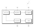
도 1은 본 발명의 실시예에 따른 영상처리장치(1)의 구성 블록도이다.1 is a block diagram of an image processing apparatus 1 according to an exemplary embodiment of the present invention.
도 1에 도시된 바와 같이, 본 실시예에 따른 영상처리장치(1)는 외부로부터 소정의 신호를 수신하는 신호수신부(100)와, 신호수신부(100)에 수신되는 신호 중에서 영상신호를 처리하는 영상처리부(200)와, 영상처리부(200)에 의해 처리되는 영상신호에 기초하여 영상을 표시하는 디스플레이부(300)와, 신호수신부(100)에 수신되는 신호 중에서 음성신호를 처리하는 음성처리부(400)와, 음성처리부(400)에 의해 처리되는 음성신호에 기초하여 음성을 출력하는 스피커(500)를 포함한다.As shown in FIG. 1, the image processing apparatus 1 according to the present embodiment is configured to process an image signal among a
본 실시예에서는 디스플레이부(300)를 가진 영상처리장치(1)에 관하여 표현하나, 본 발명의 사상은 이에 한정되지 않는다. 예를 들면, 본 발명의 사상은 디스플레이부(300)를 가지지 않은 영상처리장치나, 또는 영상처리장치에 한정되지 않고 음성신호를 처리 및 출력 가능한 다양한 음성처리장치에서도 구현될 수 있다.In the present embodiment, the image processing apparatus 1 having the
신호수신부(100)는 한정되지 않는 다양한 공급원(미도시)으로부터 영상신호 및 음성신호 중 적어도 어느 하나를 수신한다. 신호수신부(100)는 방송국으로부터 송출되는 RF(radio frequency) 신호를 무선으로 수신하거나, 컴포지트(composite) 비디오, 컴포넌트(component) 비디오, 슈퍼 비디오(super video), SCART, HDMI(high definition multimedia interface) 규격 등에 의한 영상신호를 유선으로 수신할 수 있다. 또는, 신호수신부(100)는 웹 서버(미도시)에 접속됨으로써, 웹 컨텐츠의 데이터 패킷(data packet)을 수신할 수 있다.The
신호수신부(100)가 방송신호를 수신하는 경우, 신호수신부(100)는 수신되는 방송신호를 영상신호 및 음성신호로 튜닝하고, 영상신호는 영상처리부(200)에, 음성신호는 음성처리부(400)에 각각 전달한다.When the
영상처리부(200)는 신호수신부(100)로부터 전달되는 영상신호에 대해 기 설정된 다양한 영상처리 프로세스를 수행한다. 영상처리부(200)는 이러한 프로세스를 수행한 영상신호를 디스플레이부(300)에 출력함으로써, 디스플레이부(300)에 영상이 표시되게 한다.The
영상처리부(200)가 수행하는 영상처리 프로세스의 종류는 한정되지 않는 바, 예를 들면, 다양한 영상 포맷에 대응하는 디코딩(decoding), 디인터레이싱(de-interlacing), 프레임 리프레시 레이트(frame refresh rate) 변환, 스케일링(scaling), 영상 화질 개선을 위한 노이즈 감소(noise reduction) 처리, 디테일 강화(detail enhancement) 등 다양한 처리 구성을 포함할 수 있다. 영상처리부(200)는 이러한 각 프로세스를 독자적으로 수행하는 개별적 구성으로 구현되거나, 또는 시스템 온 칩(system-on-chip)과 같이 여러 기능을 통합시킨 일체형 구성으로 구현될 수도 있다.The type of the image processing process performed by the
디스플레이부(300)는 영상처리부(200)로부터 출력되는 영상신호에 기초한 영상을 표시한다. 이러한 디스플레이부(300)의 구현 방식은 한정되지 않는 바, 액정(liquid crystal), 플라즈마(plasma), 발광 다이오드(light-emitting diode), 유기발광 다이오드(organic light-emitting diode), 면전도 전자총(surface-conduction electron-emitter), 탄소 나노 튜브(carbon nano-tube), 나노 크리스탈(nano-crystal) 등의 다양한 디스플레이 방식으로 구현될 수 있다.The
음성처리부(400)는 신호수신부(100)로부터 수신되는 음성신호를 처리하여 스피커(500)로 출력한다. 음성처리부(400)는 복수 채널의 음성신호가 수신되면 스피커(500)의 채널에 대응하도록 각 채널별 음성신호를 처리한다. 예를 들면, 스피커(500)가 2채널에 대응하는 상태에서 5채널 음성신호가 수신되면, 음성처리부(400)는 5채널 음성신호가 각 채널을 좌측 채널 및 우측 채널로 재구성하여 스피커(500)로 출력한다. 이에, 스피커(500)는 좌우 채널 별로 수신되는 음성신호를 각각 음성으로 출력시킨다.The
여기서, 음성처리부(400)에 수신되는 음성신호의 채널에 관하여 도 2를 참조하여 이하 설명한다. 도 2는 5채널 음성신호에 대한 음상(sound image) 내 채널의 배치를 나타내는 예시도이다. 본 실시예에서는 음성신호가 5채널에 대응하는 것으로 표현하나, 음성신호의 채널 수는 특정 수치로 한정되지 않는 바, 이러한 예시가 본 발명의 사상을 한정하지 않는다.Here, a channel of the voice signal received by the
도 2에 도시된 바와 같이, 음상에서 좌우방향 축선 X와 전후방향 축선 Y이 직교하는 중심에 사용자(U)가 있다고 한다. 5채널 음성신호의 경우, 각 채널별 음성신호는 사용자(U)를 기준으로 각각 전방 좌측 채널(FL), 전방 우측 채널(FR), 전방 중앙 채널(FC), 후방/서라운드(surround) 좌측 채널(BL), 후방/서라운드 우측 채널(BR)로 구성된다. 이와 같이, 음성신호의 각 채널(FL, FR, FC, BL, BR)이 음상에서 사용자(U) 주위의 각 위치에 대응함으로써, 사용자는 음성신호가 음성으로 출력될 때 이 음성을 3차원적으로 인지할 수 있다.As shown in FIG. 2, it is assumed that the user U is at a center where the left and right directions X and the front and back directions Y are perpendicular to each other in the sound image. In case of 5-channel audio signal, the audio signal for each channel is based on user U, front left channel (FL), front right channel (FR), front center channel (FC), and rear / surround left channel respectively. (BL), the rear / surround right channel BR. In this way, each channel (FL, FR, FC, BL, BR) of the voice signal corresponds to each position around the user U in the sound image, so that the user can make the voice three-dimensional when the voice signal is output as voice. It can be recognized as
음성처리부(400)는 사용자가 음성을 3차원적으로 인지 가능하도록 복수 채널의 음성신호를 처리함에 있어서, 각 채널 별 음성신호에 대해 기 설정된 머리전달함수(Head Related Transfer Function, HRTF) 필터링을 수행한다.The
머리전달함수는 인간의 머리를 사이에 두고 이격된 두 귀를 가지는 인간의 청각인식 구조상에서 발생하는 음성 주파수의 변화를 함수 관계로 정리한 것으로서, 즉 사용자의 머리에 의해 음성의 전달 및 진행에 영향을 주는 정도를 수학적으로 정리한 알고리즘이다. 머리전달함수는 두 귀 사이의 음성 레벨 차이(Inter-aural Level Difference, ILD), 두 귀 사이의 음성의 시간적 차이(Inter-aural Time Difference, ITD), 그 외에 음성의 회절 및 반사 등 다양한 인자를 반영하여, 음성신호의 소정 채널을 음상 내의 특정 위치에 대응하게 배치시킬 수 있다. 머리전달함수 알고리즘은 음향 기술 분야에서 공지된 내용인 바, 보다 자세한 설명은 생략한다.Head transfer function is a function of speech frequency change that occurs in the structure of human hearing with two ears spaced apart from each other. Algorithm that summarizes the degree of The head transfer function determines various factors such as the inter-aural level difference (ILD) between two ears, the inter-aural time difference (ITD) between two ears, and other factors such as diffraction and reflection of speech. By reflecting, a predetermined channel of the audio signal can be arranged corresponding to a specific position in the sound image. Since the head transfer function algorithm is well known in the art of sound technology, a detailed description thereof will be omitted.
그런데, 머리전달함수 알고리즘을 음성신호에 적용함에 있어서, 머리전달함수의 적용은 사용자로 하여금 좌우방향에 따른 음상의 구별은 상대적으로 용이하게 하는 반면, 전후방향에 따른 음상의 구별은 상대적으로 곤란하게 할 수 있다.However, in applying the head transfer function algorithm to the voice signal, the application of the head transfer function makes it easier for the user to distinguish the images in the left and right directions, while it is relatively difficult to distinguish the images in the front and back directions. can do.
예를 들어, 사용자(U)가 음성을 3차원적으로 인식하기 위해서는 후방 채널(BL, BR)의 음성신호의 음상이 사용자(U)의 후방에 형성되어야 하는데, 머리전달함수의 특성 상 사용자(U)의 후방이 아닌 사용자(U)의 전방 또는 머리 속 등의 위치에 음상이 형성되는 전후방 혼동 현상(front/back confusion)이 발생할 수 있다. 또는, 후방 좌측 채널(BL) 및 후방 우측 채널(BR)의 음상이 각각 사용자(U)의 후방 좌측 및 후방 우측에 형성되는 것이 아닌, 후방 중앙에 형성되는 경우도 발생할 수 있다.For example, in order for the user U to recognize the voice in three dimensions, a sound image of the voice signal of the rear channels BL and BR should be formed at the rear of the user U. Front / back confusion may occur in which sound image is formed at a position such as the front of the user U or the head rather than the back of U). Alternatively, the sound image of the rear left channel BL and the rear right channel BR may be formed at the rear center instead of being formed at the rear left and rear right of the user U, respectively.
본 실시예에 따르면, 음성처리부(400)는 복수 채널의 음성신호가 수신되면 이 음성신호에서 음상 내 소정의 기준축을 중심으로 상호 대칭하는 위치에 대응하는 제1채널신호 및 제2채널신호를 판별한다. 그리고, 음성처리부(400)는 제1채널신호 및 제2채널신호 사이의 에너지 차이 변화에 기초하여 제1채널신호 및 제2채널신호를 보정 처리한다. 이에 의하여, 상기한 전후방 혼동 현상과 같은 상황을 방지하고 사용자가 음성을 3차원적으로 보다 명확히 인지할 수 있도록 할 수 있다.According to the present exemplary embodiment, when a plurality of channel voice signals are received, the
이하, 본 실시예에 따른 음성처리부(400)의 보다 구체적인 구성에 관해 도 3을 참조하여 설명한다. 도 3은 음성처리부(400)의 구성 블록도이다.Hereinafter, a more specific configuration of the
도 3에 도시된 바와 같이, 음성처리부(400)는 신호수신부(100)에서 수신되는 음성신호의 각 채널신호에 대해 상호 대칭하는 제1채널신호 및 제2채널신호로 맵핑하는 맵핑부(410)와, 제1채널신호 및 제2채널신호 사이의 에너지 차이 변화에 기초하여 음원의 이동에 따른 위치변화정보를 산출하는 위치산출부(420)와, 위치산출부(420)에 의해 산출된 위치변화정보에 대응하는 머리전달함수 계수를 선택하는 계수선택부(430)와, 계수선택부(430)에 의해 선택된 머리전달함수 계수를 반영하여 제1채널신호 및 제2채널신호를 HRTF 필터링하는 필터부(440)와, 필터부(440)에서 출력되는 각 채널 별 음성신호를 스피커(500)에 대응하는 채널로 정리하여 출력하는 가산부(450)를 포함한다.As shown in FIG. 3, the
맵핑부(410)는 신호수신부(100)로부터 예를 들어 5채널 음성신호(600)가 수신되면, 이 음성신호(600)의 각 채널별 신호를 음상 내의 기 설정된 기준축을 중심으로 상호 대칭하는 위치에 대응하는 쌍(pair)으로 맵핑한다. 이하, 맵핑된 한 쌍에 포함되는 두 채널별 신호를 제1채널신호 및 제2채널신호로 지칭한다.When the
이러한 기준축은 음상에서 사용자(U) 위치를 포함하는 수평축 또는 수직축으로 지정될 수 있으며, 도 2의 예를 들면, 일단 사용자(U)를 포함하는 수평축인 Y 축선을 중심으로 채널 FL 및 채널 FR의 첫 번째 쌍, 채널 BL 및 채널 BR의 두 번째 쌍으로 맵핑이 가능하다. 그리고 채널 FC의 경우는 X 축선을 중심으로 상호 대칭되게 배치되는 채널이 없으므로, 맵핑부(410)는 채널 FC는 맵핑에서 제외하고 별도 처리되도록 하거나, 또는 채널 BL 및 BR을 합산한 채널 및 채널 FC의 세 번째 쌍이 되도록 맵핑할 수도 있다.This reference axis may be designated as a horizontal axis or a vertical axis including the user (U) position on the sound image. For example, in FIG. It is possible to map to the second pair of the first pair, channel BL and channel BR. In the case of the channel FC, since there are no channels arranged symmetrically with respect to the X axis, the
맵핑부(410)는 음성신호(600)를 세 쌍(610 및 620, 630 및 640, 650 및 660)으로 맵핑하여 출력한다. 이하 예시에서는 첫 번째 쌍(610, 620)의 채널신호에 관한 처리 구성에 관해서 설명하며, 그 외의 쌍(630, 640, 650, 660)의 채널신호에 관해서는 이하 실시예를 응용하여 적용할 수 있는 바 자세한 설명을 생략한다.The
위치산출부(420)는 맵핑부(410)에서 출력되는 한 쌍의 제1채널신호(610) 및 제2채널신호(620)의 에너지 차이 변화에 기초하여, 도 4에 도시된 바와 같이 사용자(U)에 대한 가상 음원(S)의 이동 위치를 산출한다. 도 4는 사용자(U)에 대하여 음원(S)이 이동하는 모습을 나타내는 예시도이다.The
도 4에 도시된 바와 같이, 초기위치 P0에 있는 음원(S)이 이동위치 P1으로 이동한다고 할 때, 사용자(U)는 시간에 따른 음원(S)의 이동에 따라서 두 귀에 인식되는 음성의 레벨 및 거리감이 달라지게 된다. 따라서, 기준축을 중심으로 상호 대칭하는 제1채널신호(610) 및 제2채널신호(620)의 에너지 차이 변화를 산출하면 음원(S)의 상대적인 위치 변화를 산출할 수 있다. 여기서, 에너지 차이 변화는 제1채널신호(610) 및 제2채널신호(620) 사이의 음성 레벨 차이의 변화를 포함한다.As shown in FIG. 4, when the sound source S at the initial position P0 is moved to the movement position P1, the user U has a level of speech recognized by both ears according to the movement of the sound source S with time. And the sense of distance will be different. Therefore, when the change in energy difference between the
즉, 제1채널신호(610) 및 제2채널신호(620) 각각의 에너지량이 시간에 따라서 변화할 때, 이 에너지 차이 변화를 이동벡터값으로 산출함으로써 음원(S)의 상대적 이동 위치를 산출 가능하다.That is, when the amount of energy of each of the
이하, 사용자(U)에 대한 음원(S)의 위치를 3차원적으로 표시하는 예시에 관해 도 5를 참조하여 설명한다. 도 5는 위치 R0에서 위치 R1으로 이동하는 경우, 위치변화에 따른 벡터 관계를 3차원적으로 나타내는 예시도이다.Hereinafter, an example of three-dimensionally displaying the position of the sound source S with respect to the user U will be described with reference to FIG. 5. 5 is an exemplary diagram illustrating a three-dimensional vector relationship according to a change in position when moving from the position R0 to the position R1.
도 5에 도시된 바와 같이, X축, Y축, Z축 상에서 소정의 물체가 위치 R0에서 위치 R1로 이동한 경우의 이동벡터값을


여기서, r은 위치 R0 및 위치 R1 사이의 거리, θ는 수평방향 각도 변화량, Φ는 수직방향 각도 변화량이다.Here, r is the distance between the position R0 and the position R1, θ is the horizontal angle change amount, Φ is the vertical angle change amount.
위치산출부(420)는 이와 같이 제1채널신호(610) 및 제2채널신호(620) 사이의 에너지 차이 변화에 기초하여 음원(S)의 이동에 따른 위치변화정보, 즉 음원(S)의 이동벡터값을 산출한다. 이 이동벡터값은 음원(S)의 수평방향 각도 변화정보 및 수직방향 각도 변화정보를 포함하며, 위치산출부(420)는 이와 같이 산출된 음원(S)의 위치변화정보를 도 3에 도시된 바와 같이 계수선택부(430)에 전달한다.The
여기서, 위치산출부(420)는 제1채널신호(610) 및 제2채널신호(620) 사이의 에너지 차이 변화량을 산출하기 이전에, 제1채널신호(610) 및 제2채널신호(620) 사이를 코렐레이션(correlation) 분석한다. 코렐레이션 분석은 비교 대상이 되는 두 신호/코드/데이터 간의 관계의 밀접한 정도 또는 상호 유사한 정도, 즉 상관관계를 분석하는 통계적 분석 방법을 지칭한다. 코렐레이션 분석은 공지된 통계분석 기법인 바, 본 실시예에서 자세한 설명은 생략한다.Here, the
위치산출부(420)는 코렐레이션 분석 결과, 제1채널신호(610) 및 제2채널신호(620) 사이의 상관도가 유사한 것으로 판단되는 경우에 상기한 에너지 차이 변화를 산출하고, 제1채널신호(610) 및 제2채널신호(620) 사이의 상관도가 유사하지 않은 것으로 판단되는 경우에 상기한 에너지 차이 변화를 산출하지 않는다. 이는, 위치산출부(420)는 전자의 경우가 음원(S)이 이동하는 것에 의한 것으로 판단하며, 후자의 경우가 동일 음원(S)이 아닌 다른 음원에 의한 것으로 판단하는 것에 따른 것이다.The
즉, 위치산출부(420)는 코렐레이션 분석을 통해 제1채널신호(610) 및 제2채널신호(620) 사이의 에너지 차이 변화가 동일 음원(S)에 의한 것인지를 판별하고, 동일 음원(S)에 의한 것이 아니라고 판단되는 경우에는 후술할 필터부(440)에 의한 제1채널신호(610) 및 제2채널신호(620)의 보정 처리 시에 반영되는 머리전달함수 계수의 변경이 수행되지 않도록 한다.That is, the
계수선택부(430)는 음원(S)의 위치변화정보, 보다 자세하게는 음원(S)의 수평방향 및 수직방향 각각의 각도 변화량에 대응하는 머리전달함수 계수가 테이블(table) 형식으로 기 설정되어 있다. 위치산출부(420)로부터 음원(S)의 위치변화정보가 수신되면, 계수선택부(430)는 이 수신되는 위치변화정보에 대응하는 머리전달함수 계수를 선택하여 필터부(440)에 전달한다.The
계수선택부(430)는 본 실시예에 따르면 테이블 형식으로 머리전달함수 계수를 저장하고 있으나, 이는 하나의 예시에 불과하며 본 발명의 사상을 한정하지 않는다. 계수선택부(430)는 기 설정된 다양한 알고리즘을 통해 음원(S)의 위치변화정보로부터 대응하는 머리전달함수 계수를 도출할 수 있다.The
필터부(440)는 맵핑부(410)로부터 출력되는 각 채널별 신호(610, 620, 630, 640, 650, 660)에 대하여 머리전달함수를 적용하여 필터링을 수행한다. 특히, 필터부(440)는 제1채널신호(610) 및 제2채널신호(620)에 대응하는 머리전달함수 계수가 계수선택부(430)로부터 수신되면, 이 수신된 계수를 반영하여 제1채널신호(610) 및 제2채널신호(620)를 필터링 보정한다.The
필터부(440)는 그 외의 채널별 신호(630, 640, 650, 660) 또한 동일한 원리에 따라서 필터링하여, 필터링 보정된 채널 별 신호(611, 621, 631, 641, 651, 661)을 가산부(450)에 출력한다.The
가산부(450)는 필터부(440)로부터 출력되는 채널 별 음성신호(611, 621, 631, 641, 651, 661)를 스피커(500)의 채널 수, 예를 들면 2채널에 대응하게 재구성한다. 예를 들면, 가산부(450)는 음성신호(611, 621, 631, 641, 651, 661)를 좌측채널신호(670) 및 우측채널신호(680)로 재구성하여 스피커(500)에 출력하며, 그 재구성 방법은 다양한 구성이 적용되어 구현 가능한 사항인 바, 자세한 설명을 생략한다.The
이와 같이, 본 실시예에 따르면, 음원(S)의 이동에 따른 음원(S)의 위치 변화를 도출하고, 도출된 음원(S)의 위치 변화에 대응하여 음성신호의 각 채널에 대해 상이한 계수를 반영하여 HRTF 필터링을 수행할 수 있다. 이에 의하여, 사용자가 음성을 보다 3차원적으로 인식할 수 있도록 할 수 있다.As described above, according to the present exemplary embodiment, a change in the position of the sound source S according to the movement of the sound source S is derived, and different coefficients for each channel of the voice signal are corresponding to the derived position change of the sound source S. HRTF filtering can be performed by reflecting. As a result, the user can recognize the voice more three-dimensionally.
한편, 음성처리부(400)는, 기 설정 시간 동안에 음원(S)이 이동하지 않는 것으로 판단되면, 소정 범위 내에서 상기한 수평방향 각도 및 수직방향 각도 중 적어도 어느 하나를 연속적으로 변화시킨다. 이는 음원(S)이 정지된 상태에서 시간이 경과함에 따라서 사용자(U)가 음원(S)의 현재 위치를 놓치는, 즉 음원(S)의 위치를 인지하지 못할 수 있는 경우를 대비한 것이다.On the other hand, if it is determined that the sound source S does not move during the preset time, the
이에, 음성처리부(400)는 음원(S)이 초기위치(P0)에서 이동위치(P1)로 이동한 후, 이 이동위치(P1)에서 음원(S)이 소정 시간동안 이동하지 않는 것으로 판단되는 경우에, 음원(S)의 수평방향 각도 및 수직방향 각도 중 적어도 어느 하나를 기 설정된 범위 내에서 연속적으로 변화시킨다. 이에, 사용자(U)는 음원(S)의 위치를 명확히 인지할 수 있다.Therefore, the
이하, 본 실시예에 따른 영상처리장치(1)의 음성처리방법에 관해 도 6을 참조하여 설명한다. 도 6은 이러한 과정을 나타낸 제어 흐름도이다.Hereinafter, a sound processing method of the image processing apparatus 1 according to the present embodiment will be described with reference to FIG. 6. 6 is a control flowchart illustrating this process.
도 6에 도시된 바와 같이, 영상처리장치(1)에 음성신호가 수신되면(S100), 음성처리부(400)는 음성신호에 대하여 음상 내의 기 설정된 기준축을 중심으로 상호 대칭되는 제1채널신호(610) 및 제2채널신호(620)로 맵핑한다(S110).As shown in FIG. 6, when an audio signal is received by the image processing apparatus 1 (S100), the
음성처리부(400)는 제1채널신호(610) 및 제2채널신호(620) 각각의 에너지량을 측정하며(S120), 제1채널신호(610) 및 제2채널신호(620) 사이의 에너지 차이 변화에 기초하여 음원(S)의 이동벡터값을 산출한다(S130).The
음성처리부(400)는 산출된 이동벡터값에 대응하는 머리전달함수 계수를 선택하며(S140), 선택된 머리전달함수 계수를 적용하여 제1채널신호(610) 및 제2채널신호(620)를 HRTF 필터링 처리한다(S150).The
한편, 상기 실시예에서는 본 발명의 사상이 영상처리장치(1)에 적용되는 것으로 설명하였으나, 본 발명의 사상은 이에 한정되지 않고 음성처리장치(700)에도 적용될 수 있다. 이러한 실시예에 관해 도 7을 참조하여 이하 설명한다. 도 7은 본 발명의 다른 실시예에 따른 음성처리장치(700)의 구성 블록도이다.Meanwhile, in the above embodiment, the idea of the present invention is described as being applied to the image processing apparatus 1, but the idea of the present invention is not limited thereto and may be applied to the
도 7에 도시된 바와 같이, 본 실시예에 따른 음성처리장치(700)는 외부로부터 음성신호를 수신하는 신호수신부(710)와, 신호수신부(710)에 수신되는 음성신호를 처리하는 음성처리부(720)와, 음성처리부(720)에 의해 처리되는 음성신호에 기초하여 음성이 출력되는 스피커(730)를 포함한다.As shown in FIG. 7, the
신호수신부(710), 음성처리부(720), 스피커(730)는 앞 실시예에서 설명한 신호수신부(100), 음성처리부(400), 스피커(500)의 구성을 응용할 수 있는 바, 자세한 설명을 생략한다.The
상기한 실시예는 예시적인 것에 불과한 것으로, 당해 기술 분야의 통상의 지식을 가진 자라면 다양한 변형 및 균등한 타 실시예가 가능하다. 따라서, 본 발명의 진정한 기술적 보호범위는 하기의 특허청구범위에 기재된 발명의 기술적 사상에 의해 정해져야 할 것이다.The above-described embodiments are merely illustrative, and various modifications and equivalents may be made by those skilled in the art. Therefore, the true technical protection scope of the present invention will be defined by the technical spirit of the invention described in the claims below.
1 : 영상처리장치
100 : 신호수신부
200 : 영상처리부
300 : 디스플레이부
400 : 음성처리부
410 : 맵핑부
420 : 위치산출부
430 : 계수선택부
440 : 필터부
450 : 가산부
500 : 스피커1: Image processing device
100: signal receiver
200: image processing unit
300: display unit
400: voice processing unit
410: mapping unit
420: location calculation unit
430: coefficient selection unit
440: filter unit
450: Adder
500: Speaker
Claims (17)
Translated fromKorean영상신호 및 음성신호를 수신하는 신호수신부와;
상기 신호수신부에 수신되는 영상신호를 표시 가능하게 처리하는 영상처리부와;
상기 신호수신부에 수신되는 채널별 음성신호에서 소정의 기준축을 중심으로 상호 대칭하는 위치에 대응하는 제1채널신호 및 제2채널신호를 판별하고, 상기 제1채널신호 및 상기 제2채널신호 사이의 에너지 차이 변화에 기초하여 상기 제1채널신호 및 상기 제2채널신호를 보정 처리하는 음성처리부를 포함하는 것을 특징으로 하는 영상처리장치.An image processing apparatus comprising:
A signal receiver which receives a video signal and an audio signal;
An image processor which displays a video signal received by the signal receiver to enable display;
A first channel signal and a second channel signal corresponding to mutually symmetrical positions of a channel-specific voice signal received from the signal receiver are determined, and between the first channel signal and the second channel signal are determined. And a sound processor for correcting the first channel signal and the second channel signal based on a change in energy difference.
상기 음성처리부는, 상기 에너지 차이 변화에 기초하여 음원의 이동에 따른 위치변화 정보를 산출하며, 상기 산출된 위치변화 정보에 대응하게 기 설정된 머리전달함수(Head Related Transfer Function, HRTF) 계수를 선택하여 상기 제1채널신호 및 상기 제2채널신호에 대해 필터링 처리하는 것을 특징으로 하는 영상처리장치.The method of claim 1,
The voice processor calculates position change information according to movement of a sound source based on the change in energy difference, and selects a preset Head Related Transfer Function (HRTF) coefficient corresponding to the calculated position change information. And filtering the first channel signal and the second channel signal.
상기 위치변화 정보는, 사용자에 대한 상기 음원의 수평방향 각도 및 수직방향 각도의 변화 정보를 포함하는 것을 특징으로 하는 영상처리장치.The method of claim 2,
And the position change information includes change information of a horizontal angle and a vertical angle of the sound source with respect to a user.
상기 음성처리부는, 기 설정 시간 동안에 상기 음원이 이동하지 않는 것으로 판단되면, 소정 범위 내에서 상기 수평방향 각도 및 상기 수직방향 각도 중 적어도 어느 하나를 연속적으로 변화시키는 것을 특징으로 하는 영상처리장치.The method of claim 3,
And the sound processor is configured to continuously change at least one of the horizontal angle and the vertical angle within a predetermined range when it is determined that the sound source does not move during a predetermined time.
상기 음성처리부는,
상기 음성신호의 각 채널신호에 대하여 상기 제1채널신호 및 상기 제2채널신호로 맵핑하는 맵핑부와;
상기 제1채널신호 및 상기 제2채널신호 사이의 에너지 차이 변화에 기초하여 음원의 이동벡터값을 계산하는 위치산출부와;
상기 계산된 이동벡터값에 대응하는 머리전달함수 계수에 의해 상기 제1채널신호 및 상기 제2채널신호를 보정 처리하는 필터부를 포함하는 것을 특징으로 하는 영상처리장치.The method of claim 1,
The voice processing unit,
A mapping unit for mapping each channel signal of the voice signal to the first channel signal and the second channel signal;
A position calculator for calculating a moving vector value of a sound source based on a change in energy difference between the first channel signal and the second channel signal;
And a filter unit which corrects the first channel signal and the second channel signal by a head transfer function coefficient corresponding to the calculated motion vector value.
상기 음성처리부는,
상기 제1채널신호 및 상기 제2채널신호 사이를 코렐레이션(correlation) 분석하고,
상기 코렐레이션 분석 결과, 상기 제1채널신호 및 상기 제2채널신호 사이의 상관도가 유사한 것으로 판단되는 경우에 상기 제1채널신호 및 상기 제2채널신호 사이의 에너지 차이 변화를 산출하는 것을 특징으로 하는 영상처리장치.The method of claim 1,
The voice processing unit,
Correlation analysis between the first channel signal and the second channel signal,
Calculating a difference in energy difference between the first channel signal and the second channel signal when it is determined that the correlation between the first channel signal and the second channel signal is similar. Image processing apparatus.
상기 에너지 차이 변화는 상기 제1채널신호 및 상기 제2채널신호 사이의 음성 레벨 차이의 변화를 포함하는 것을 특징으로 하는 영상처리장치.The method of claim 1,
And wherein the change in energy difference comprises a change in sound level difference between the first channel signal and the second channel signal.
상기 기준축은 사용자의 위치를 포함하는 수평축 또는 수직축을 포함하는 것을 특징으로 하는 영상처리장치.The method of claim 1,
And the reference axis includes a horizontal axis or a vertical axis including a position of a user.
외부로부터 수신되는 복수 채널의 음성신호에서 소정의 기준축을 중심으로 상호 대칭하는 위치에 대응하는 제1채널신호 및 제2채널신호를 판별하는 단계와;
상기 제1채널신호 및 상기 제2채널신호 사이의 에너지 차이 변화에 기초하여 상기 제1채널신호 및 상기 제2채널신호를 보정 처리하는 단계를 포함하는 것을 특징으로 하는 영상처리장치에 사용되는 음성처리방법.In the audio processing method used in the image processing apparatus,
Determining a first channel signal and a second channel signal corresponding to positions symmetrical with respect to a predetermined reference axis in a plurality of audio signals received from the outside;
Correcting the first channel signal and the second channel signal on the basis of a change in energy difference between the first channel signal and the second channel signal. Way.
상기 제1채널신호 및 상기 제2채널신호를 보정 처리하는 단계는,
상기 에너지 차이 변화에 기초하여 음원의 이동에 따른 위치변화 정보를 산출하는 단계와;
상기 산출된 위치변화 정보에 대응하게 기 설정된 머리전달함수 계수를 선택하여 상기 제1채널신호 및 상기 제2채널신호에 대해 필터링 처리하는 단계를 포함하는 것을 특징으로 하는 영상처리장치에 사용되는 음성처리방법.10. The method of claim 9,
Compensating the first channel signal and the second channel signal,
Calculating position change information according to movement of a sound source based on the change in energy difference;
And processing the first channel signal and the second channel signal by selecting a preset head transfer function coefficient corresponding to the calculated position change information. Way.
상기 위치변화 정보는, 사용자에 대한 상기 음원의 수평방향 각도 및 수직방향 각도의 변화 정보를 포함하는 것을 특징으로 하는 영상처리장치에 사용되는 음성처리방법.The method of claim 10,
And the position change information includes change information of a horizontal angle and a vertical angle of the sound source with respect to a user.
상기 음원의 이동에 따른 위치변화 정보를 산출하는 단계는, 기 설정 시간 동안에 상기 음원이 이동하지 않는 것으로 판단되면, 소정 범위 내에서 상기 수평방향 각도 및 상기 수직방향 각도 중 적어도 어느 하나를 연속적으로 변화시키는 단계를 더 포함하는 것을 특징으로 하는 영상처리장치에 사용되는 음성처리방법.The method of claim 11,
Computing the position change information according to the movement of the sound source, if it is determined that the sound source does not move for a predetermined time, continuously changing at least one of the horizontal angle and the vertical angle within a predetermined range. The audio processing method used in the image processing apparatus further comprising the step of making.
상기 제1채널신호 및 상기 제2채널신호를 보정 처리하는 단계는,
상기 제1채널신호 및 상기 제2채널신호 사이의 에너지 차이 변화에 기초하여 음원의 이동벡터값을 계산하는 단계와;
상기 계산된 이동벡터값에 대응하는 머리전달함수 계수에 의해 상기 제1채널신호 및 상기 제2채널신호를 필터링 처리하는 단계를 포함하는 것을 특징으로 하는 영상처리장치에 사용되는 음성처리방법.10. The method of claim 9,
Compensating the first channel signal and the second channel signal,
Calculating a moving vector value of a sound source based on a change in energy difference between the first channel signal and the second channel signal;
And filtering the first channel signal and the second channel signal by a head transfer function coefficient corresponding to the calculated motion vector value.
상기 제1채널신호 및 상기 제2채널신호를 보정 처리하는 단계는,
상기 제1채널신호 및 상기 제2채널신호 사이를 코렐레이션 분석하는 단계와;
상기 코렐레이션 분석 결과, 상기 제1채널신호 및 상기 제2채널신호 사이의 상관도가 유사한 것으로 판단되는 경우에 상기 제1채널신호 및 상기 제2채널신호 사이의 에너지 차이 변화를 산출하는 단계를 포함하는 것을 특징으로 하는 영상처리장치에 사용되는 음성처리방법.10. The method of claim 9,
Compensating the first channel signal and the second channel signal,
Performing a correlation analysis between the first channel signal and the second channel signal;
Calculating a change in energy difference between the first channel signal and the second channel signal when it is determined that the correlation between the first channel signal and the second channel signal is similar. An audio processing method used in an image processing apparatus, characterized in that.
상기 에너지 차이 변화는 상기 제1채널신호 및 상기 제2채널신호 사이의 음성 레벨 차이의 변화를 포함하는 것을 특징으로 하는 영상처리장치에 사용되는 음성처리방법.10. The method of claim 9,
The change in energy difference includes a change in sound level difference between the first channel signal and the second channel signal.
상기 기준축은 사용자의 위치를 포함하는 수평축 또는 수직축을 포함하는 것을 특징으로 하는 영상처리장치에 사용되는 음성처리방법.10. The method of claim 9,
And the reference axis includes a horizontal axis or a vertical axis including a position of a user.
음성신호를 수신하는 신호수신부와;
상기 신호수신부에 수신되는 채널별 음성신호에서 소정의 기준축을 중심으로 상호 대칭하는 위치에 대응하는 제1채널신호 및 제2채널신호를 판별하고, 상기 제1채널신호 및 상기 제2채널신호 사이의 에너지 차이 변화에 기초하여 상기 제1채널신호 및 상기 제2채널신호를 보정 처리하는 음성처리부를 포함하는 것을 특징으로 하는 음성처리장치.In the voice processing device,
A signal receiver for receiving a voice signal;
A first channel signal and a second channel signal corresponding to mutually symmetrical positions of a channel-specific voice signal received from the signal receiver are determined, and between the first channel signal and the second channel signal are determined. And a voice processor for correcting the first channel signal and the second channel signal based on a change in energy difference.
Priority Applications (3)
| Application Number | Priority Date | Filing Date | Title |
|---|---|---|---|
| KR1020100101619AKR20120040290A (en) | 2010-10-19 | 2010-10-19 | Image processing apparatus, sound processing method used for image processing apparatus, and sound processing apparatus |
| US13/158,691US20120092566A1 (en) | 2010-10-19 | 2011-06-13 | Image processing apparatus, sound processing method used for image processing apparatus, and sound processing apparatus |
| EP11170674.3AEP2445234A3 (en) | 2010-10-19 | 2011-06-21 | Image processing apparatus, sound processing method used for image processing apparatus, and sound processing apparatus |
Applications Claiming Priority (1)
| Application Number | Priority Date | Filing Date | Title |
|---|---|---|---|
| KR1020100101619AKR20120040290A (en) | 2010-10-19 | 2010-10-19 | Image processing apparatus, sound processing method used for image processing apparatus, and sound processing apparatus |
Publications (1)
| Publication Number | Publication Date |
|---|---|
| KR20120040290Atrue KR20120040290A (en) | 2012-04-27 |
Family
ID=44681014
Family Applications (1)
| Application Number | Title | Priority Date | Filing Date |
|---|---|---|---|
| KR1020100101619AWithdrawnKR20120040290A (en) | 2010-10-19 | 2010-10-19 | Image processing apparatus, sound processing method used for image processing apparatus, and sound processing apparatus |
Country Status (3)
| Country | Link |
|---|---|
| US (1) | US20120092566A1 (en) |
| EP (1) | EP2445234A3 (en) |
| KR (1) | KR20120040290A (en) |
Cited By (1)
| Publication number | Priority date | Publication date | Assignee | Title |
|---|---|---|---|---|
| WO2018012746A1 (en)* | 2016-07-13 | 2018-01-18 | 삼성전자 주식회사 | Electronic device and audio output method for electronic device |
Families Citing this family (2)
| Publication number | Priority date | Publication date | Assignee | Title |
|---|---|---|---|---|
| EP2997573A4 (en) | 2013-05-17 | 2017-01-18 | Nokia Technologies OY | Spatial object oriented audio apparatus |
| CN106373582B (en)* | 2016-08-26 | 2020-08-04 | 腾讯科技(深圳)有限公司 | Method and device for processing multi-channel audio |
Family Cites Families (6)
| Publication number | Priority date | Publication date | Assignee | Title |
|---|---|---|---|---|
| US7113610B1 (en)* | 2002-09-10 | 2006-09-26 | Microsoft Corporation | Virtual sound source positioning |
| JP4273343B2 (en)* | 2005-04-18 | 2009-06-03 | ソニー株式会社 | Playback apparatus and playback method |
| EP1938661B1 (en)* | 2005-09-13 | 2014-04-02 | Dts Llc | System and method for audio processing |
| US8351611B2 (en)* | 2006-01-19 | 2013-01-08 | Lg Electronics Inc. | Method and apparatus for processing a media signal |
| US8374365B2 (en)* | 2006-05-17 | 2013-02-12 | Creative Technology Ltd | Spatial audio analysis and synthesis for binaural reproduction and format conversion |
| JP2010118977A (en)* | 2008-11-14 | 2010-05-27 | Victor Co Of Japan Ltd | Sound image localization control apparatus and sound image localization control method |
- 2010
- 2010-10-19KRKR1020100101619Apatent/KR20120040290A/ennot_activeWithdrawn
- 2011
- 2011-06-13USUS13/158,691patent/US20120092566A1/ennot_activeAbandoned
- 2011-06-21EPEP11170674.3Apatent/EP2445234A3/ennot_activeWithdrawn
Cited By (3)
| Publication number | Priority date | Publication date | Assignee | Title |
|---|---|---|---|---|
| WO2018012746A1 (en)* | 2016-07-13 | 2018-01-18 | 삼성전자 주식회사 | Electronic device and audio output method for electronic device |
| KR20180007718A (en)* | 2016-07-13 | 2018-01-24 | 삼성전자주식회사 | Electronic device and method for outputting audio |
| US10893374B2 (en) | 2016-07-13 | 2021-01-12 | Samsung Electronics Co., Ltd. | Electronic device and audio output method for electronic device |
Also Published As
| Publication number | Publication date |
|---|---|
| US20120092566A1 (en) | 2012-04-19 |
| EP2445234A3 (en) | 2014-04-09 |
| EP2445234A2 (en) | 2012-04-25 |
Similar Documents
| Publication | Publication Date | Title |
|---|---|---|
| US10728683B2 (en) | Sweet spot adaptation for virtualized audio | |
| US8665321B2 (en) | Image display apparatus and method for operating the same | |
| US9008338B2 (en) | Audio reproduction apparatus and audio reproduction method | |
| EP2645749B1 (en) | Audio apparatus and method of converting audio signal thereof | |
| KR101717787B1 (en) | Display device and method for outputting of audio signal | |
| US11445317B2 (en) | Method and apparatus for localizing multichannel sound signal | |
| US20130038611A1 (en) | Image conversion device | |
| US8958565B2 (en) | Apparatus for controlling depth/distance of sound and method thereof | |
| US20100266133A1 (en) | Sound processing apparatus, sound image localization method and sound image localization program | |
| EP3623913A1 (en) | Apparatus and method for processing audiovisual data | |
| US20120327077A1 (en) | Apparatus for rendering 3d images | |
| JP2011216937A (en) | Stereoscopic image display device | |
| KR101901593B1 (en) | Virtual sound producing method and apparatus for the same | |
| US11751003B1 (en) | Personalization of head-related transfer function | |
| KR20120040290A (en) | Image processing apparatus, sound processing method used for image processing apparatus, and sound processing apparatus | |
| KR102121748B1 (en) | Method and apparatus for 3d sound reproduction | |
| US8855409B2 (en) | Three-dimension image processing method and a three-dimension image display apparatus applying the same | |
| US20120224700A1 (en) | Sound image control device and sound image control method | |
| KR20120090271A (en) | Image processing apparatus and control method thereof | |
| JP5647741B2 (en) | Image signal processing apparatus and image signal processing method | |
| US20240323636A1 (en) | Sound processing device, sound processing method, and recording medium | |
| JP5977749B2 (en) | Presentation of 2D elements in 3D stereo applications | |
| KR20120020306A (en) | Apparatus and method for displaying of stereo scope images | |
| KR20250098408A (en) | Apparatus And Method for Implementing Spatial Sound | |
| JP2014225736A (en) | Image processor |
Legal Events
| Date | Code | Title | Description |
|---|---|---|---|
| PA0109 | Patent application | Patent event code:PA01091R01D Comment text:Patent Application Patent event date:20101019 | |
| PG1501 | Laying open of application | ||
| PC1203 | Withdrawal of no request for examination | ||
| WITN | Application deemed withdrawn, e.g. because no request for examination was filed or no examination fee was paid |