KR20120038467A - Method and system for asynchronous lamp identification - Google Patents
Method and system for asynchronous lamp identificationDownload PDFInfo
- Publication number
- KR20120038467A KR20120038467AKR1020127002942AKR20127002942AKR20120038467AKR 20120038467 AKR20120038467 AKR 20120038467AKR 1020127002942 AKR1020127002942 AKR 1020127002942AKR 20127002942 AKR20127002942 AKR 20127002942AKR 20120038467 AKR20120038467 AKR 20120038467A
- Authority
- KR
- South Korea
- Prior art keywords
- information signal
- code
- base code
- data
- output
- Prior art date
- Legal status (The legal status is an assumption and is not a legal conclusion. Google has not performed a legal analysis and makes no representation as to the accuracy of the status listed.)
- Withdrawn
Links
Images


Classifications
- H—ELECTRICITY
- H04—ELECTRIC COMMUNICATION TECHNIQUE
- H04B—TRANSMISSION
- H04B10/00—Transmission systems employing electromagnetic waves other than radio-waves, e.g. infrared, visible or ultraviolet light, or employing corpuscular radiation, e.g. quantum communication
- H04B10/11—Arrangements specific to free-space transmission, i.e. transmission through air or vacuum
- H04B10/114—Indoor or close-range type systems
- H04B10/116—Visible light communication
- H—ELECTRICITY
- H05—ELECTRIC TECHNIQUES NOT OTHERWISE PROVIDED FOR
- H05B—ELECTRIC HEATING; ELECTRIC LIGHT SOURCES NOT OTHERWISE PROVIDED FOR; CIRCUIT ARRANGEMENTS FOR ELECTRIC LIGHT SOURCES, IN GENERAL
- H05B45/00—Circuit arrangements for operating light-emitting diodes [LED]
- H05B45/10—Controlling the intensity of the light
- H—ELECTRICITY
- H05—ELECTRIC TECHNIQUES NOT OTHERWISE PROVIDED FOR
- H05B—ELECTRIC HEATING; ELECTRIC LIGHT SOURCES NOT OTHERWISE PROVIDED FOR; CIRCUIT ARRANGEMENTS FOR ELECTRIC LIGHT SOURCES, IN GENERAL
- H05B45/00—Circuit arrangements for operating light-emitting diodes [LED]
- H05B45/20—Controlling the colour of the light
- H—ELECTRICITY
- H05—ELECTRIC TECHNIQUES NOT OTHERWISE PROVIDED FOR
- H05B—ELECTRIC HEATING; ELECTRIC LIGHT SOURCES NOT OTHERWISE PROVIDED FOR; CIRCUIT ARRANGEMENTS FOR ELECTRIC LIGHT SOURCES, IN GENERAL
- H05B47/00—Circuit arrangements for operating light sources in general, i.e. where the type of light source is not relevant
- H05B47/10—Controlling the light source
- H05B47/175—Controlling the light source by remote control
- H05B47/19—Controlling the light source by remote control via wireless transmission
Landscapes
- Engineering & Computer Science (AREA)
- Computer Networks & Wireless Communication (AREA)
- Physics & Mathematics (AREA)
- Electromagnetism (AREA)
- Signal Processing (AREA)
- Circuit Arrangement For Electric Light Sources In General (AREA)
- Optical Communication System (AREA)
- Controls And Circuits For Display Device (AREA)
Abstract
Translated fromKoreanDescription
Translated fromKorean본 발명의 실시예들은 일반적으로 조명 시스템 및 광학 수신기의 분야에 관한 것으로, 보다 상세하게는 이러한 조명 시스템의 휘도 출력에 데이터를 임베딩하기 위한 시스템 및 방법에 관한 것이다.Embodiments of the present invention generally relate to the field of lighting systems and optical receivers, and more particularly to systems and methods for embedding data in the luminance output of such lighting systems.
최근에, 소비자들이 특정 방 또는 공간에 대해 원하는 분위기를 획득할 수 있게 하는 최첨단 조명 시스템들이 개발 중이다. 이들 조명 시스템들은 종래의 개별 광원들의 제어(스위치 온/오프 및 디밍)로부터 신 설정(scene setting)으로 이동하는데, 여기서 광원 세트들은 동시에 제어된다. 이러한 조명 시스템의 일례는 방, 로비 또는 차량에서의 수개의 광원 세트들의 배열이다.Recently, state-of-the-art lighting systems are being developed that allow consumers to obtain the desired atmosphere for a particular room or space. These lighting systems move from conventional control of individual light sources (switch on / off and dimming) to scene settings, where the light source sets are controlled simultaneously. One example of such a lighting system is an arrangement of several light sets in a room, lobby or vehicle.
이들 신 설정 애플리케이션들에 있어서, 직관적인 사용자 상호작용은 가장 중요한 성공 인자들 중 하나로서 식별된다. 광원들의 국부화된 ID(identification), 그들의 성능들 및 현재 설정들과 같은 광원들에 관련된 정보를 사용자에게 제공하는 것은 직관적인 상호작용을 가능하게 하기 위한 키이다. 이러한 정보를 사용자에게 제공하도록 제안된 하나의 기술은, 임베딩된 코드들이 소비자에게 보이지 않게 하는 방식으로 조명 장치의 휘도 출력을 변조함으로써 광원 또는 광원들의 그룹을 식별하는 임베딩 코드들("식별자들"로도 언급됨)에 기초한다. 임베딩된 코드들은, 예를 들어 조명 장치를 제어하기 위한 리모트 컨트롤에 구현될 수 있거나 또는 스위치나 센서 장치와 같은 다른 유닛에 포함될 수 있는 광학 수신기에 의해 수신된다.In these scene setup applications, intuitive user interaction is identified as one of the most important success factors. Providing the user with information related to the light sources such as localized identification of the light sources, their capabilities and current settings is the key to enabling intuitive interaction. One technique proposed to provide such information to a user is by embedding codes ("identifiers") that identify a light source or group of light sources by modulating the luminance output of the lighting device in such a way that the embedded codes are invisible to the consumer. Mentioned). The embedded codes are received by an optical receiver, which may for example be implemented in a remote control for controlling the lighting device or may be included in another unit such as a switch or sensor device.
이러한 기술의 이전의 구현들은 광원들의 광 출력 세기에 식별자들을 임베딩하는 것에 기초하였다. 그러나, 대부분의 이전의 구현들은 상이한 광원들 사이의 몇몇 종류의 동기화를 필요로 한다. 이러한 동기화는 부가적인 하드웨어를 필요로 하며, 이는 조명 시스템의 복잡도 및 비용을 증가시킨다.Previous implementations of this technique have been based on embedding identifiers in the light output intensity of the light sources. However, most previous implementations require some kind of synchronization between different light sources. This synchronization requires additional hardware, which increases the complexity and cost of the lighting system.
상술된 바와 같이, 비동기로 동작할 수 있는 광원들의 휘도 출력에 데이터를 임베딩하기 위한 기술이 본 발명이 속하는 기술분야에서 필요하다.As described above, a technique for embedding data in the luminance output of light sources that can operate asynchronously is needed in the art.
본 발명의 목적은, 조명 시스템의 휘도 출력에 데이터를 임베딩할 수 있는 조명 시스템, 조명 구조체 및 방법을 제공하는 것이다. 또한, 본 발명의 목적은, 임베딩된 데이터를 포함하는 휘도 출력을 수신 및 처리할 수 있는 광학 수신기를 제공하는 것이다.It is an object of the present invention to provide an illumination system, an illumination structure and a method capable of embedding data in the luminance output of an illumination system. It is also an object of the present invention to provide an optical receiver capable of receiving and processing a luminance output comprising embedded data.
본 발명의 일 실시예는 조명 시스템의 휘도 출력에 데이터를 임베딩하기 위한 조명 시스템을 기술한다. 이 시스템은 제1 제어기 및 제1 광원을 포함한다. 제1 제어기는, 제1 데이터를 제1 시프트된 베이스 코드에 임베딩하기 위해서 베이스 코드 기간(base code period) 내의 베이스 코드를 제1 위상 시프트로 주기적으로 시프트(circularly shifting)함으로써 제1 시프트된 베이스 코드를 생성하도록 구성된다. 제1 제어기는 또한 제1 시프트된 베이스 코드 및 동기화 코드를 포함하는 제1 정보 신호를 생성하도록 구성된다. 제1 위상 시프트는 제1 데이터에 대응한다. 제1 제어기는, 제1 데이터가 조명 시스템의 휘도 출력에 임베딩되도록 제1 정보 신호에 따라 제1 구동 신호의 제1 구동 패턴들 중 하나 이상을 변조함으로써 제1 변조된 구동 신호를 생성하도록 또한 구성된다. 제어기는 하드웨어로, 소프트웨어로, 또는 하드웨어와 소프트웨어 컴포넌트들 모두를 갖는 하이브리드 솔루션으로 구현될 수 있다. 제1 광원은 제1 변조된 구동 신호에 따라 제1 휘도 출력을 생성하도록 구성된다. 조명 시스템의 휘도 출력은 제1 휘도 출력을 포함한다.One embodiment of the invention describes an illumination system for embedding data in the luminance output of the illumination system. The system includes a first controller and a first light source. The first controller performs a first shifted base code by periodically shifting a base code within a base code period into a first phase shift to embed the first data into the first shifted base code. It is configured to generate. The first controller is further configured to generate a first information signal comprising the first shifted base code and the synchronization code. The first phase shift corresponds to the first data. The first controller is further configured to generate the first modulated drive signal by modulating one or more of the first drive patterns of the first drive signal in accordance with the first information signal such that the first data is embedded in the luminance output of the illumination system. do. The controller can be implemented in hardware, in software, or in a hybrid solution with both hardware and software components. The first light source is configured to generate a first luminance output in accordance with the first modulated drive signal. The luminance output of the lighting system includes a first luminance output.
또한, 조명 시스템의 휘도 출력에 데이터를 임베딩하는 방법이 제공된다. 이 방법은, 제1 데이터를 제1 시프트된 베이스 코드에 임베딩하기 위해서 베이스 코드 기간 내의 베이스 코드를 제1 위상 시프트로 주기적으로 시프트함으로써 제1 시프트된 베이스 코드를 생성하는 단계 - 제1 위상 시프트는 제1 데이터에 대응함 -, 및 제1 시프트된 베이스 코드 및 동기화 코드를 포함하는 제1 정보 신호를 생성하는 단계를 포함한다. 이 방법은, 제1 데이터가 조명 시스템의 휘도 출력에 임베딩되도록 제1 정보 신호에 따라 제1 구동 신호의 제1 구동 패턴들 중 하나 이상을 변조함으로써 제1 변조된 구동 신호를 생성하는 단계, 및 제1 변조된 구동 신호에 따라 제1 휘도 출력을 생성하는 단계를 더 포함하며, 조명 시스템의 휘도 출력은 제1 휘도 출력을 포함한다.Also provided is a method of embedding data in a luminance output of an illumination system. The method includes generating a first shifted base code by periodically shifting a base code within a base code period to a first phase shift to embed the first data in the first shifted base code, wherein the first phase shift is Corresponding to the first data, and generating a first information signal comprising the first shifted base code and the synchronization code. The method comprises generating a first modulated drive signal by modulating one or more of the first drive patterns of the first drive signal in accordance with the first information signal such that the first data is embedded in the luminance output of the illumination system, and Generating a first luminance output in accordance with the first modulated drive signal, wherein the luminance output of the lighting system comprises a first luminance output.
조명 장치의 휘도 출력으로부터 데이터를 검색하는 것을 가능하게 하기 위해서, 광학 수신기가 개시된다. 개시된 광학 수신기는 제1 휘도 출력을 검출하도록 구성된 광학 검출기를 포함한다. 이 수신기는, 베이스 코드 및 동기화 코드에 액세스하고, 검출된 제1 휘도 출력에 기초하여 제1 정보 신호를 검색하며, 제1 정보 신호와 동기화 코드를 상관시켜, 적어도 하나의 피크를 갖는 제1 상관 출력을 생성하도록 구성된 처리 유닛을 더 포함한다. 이 수신기는, 제1 상관 출력 내의 적어도 하나의 피크의 위치에 기초하여, 제1 정보 신호와 베이스 코드를 주기적으로 상관시켜, 하나의 피크를 갖는 제2 상관 출력을 생성하도록 또한 구성된다. 제2 상관 출력 내의 하나의 피크의 위치에 기초하여, 이 수신기는, 제1 위상 시프트를 결정하며, 이 결정된 제1 위상 시프트에 기초하여 제1 데이터를 결정하도록 구성된다. 이러한 수신기는, 예를 들어 조명 시스템을 제어하기 위한 리모트 컨트롤에 구현될 수 있거나 또는 스위치나 센서 장치와 같은 다른 유닛에 포함될 수 있다.In order to be able to retrieve data from the luminance output of the lighting device, an optical receiver is disclosed. The disclosed optical receiver includes an optical detector configured to detect a first luminance output. The receiver accesses the base code and the synchronization code, retrieves the first information signal based on the detected first luminance output, correlates the synchronization code with the first information signal, and has a first correlation with at least one peak. Further comprising a processing unit configured to generate an output. The receiver is further configured to periodically correlate the first information signal with the base code based on the position of the at least one peak in the first correlation output to produce a second correlation output with one peak. Based on the position of one peak in the second correlation output, the receiver is configured to determine a first phase shift and to determine first data based on the determined first phase shift. Such a receiver may for example be implemented in a remote control for controlling the lighting system or may be included in another unit such as a switch or sensor device.
본 명세서에서 이용된 바와 같이, 상관 출력에서의 "피크(peak)"라는 용어는 다른 모든 피크들보다 상당히 더 높은 피크를 언급한다. 상관 출력들은 통상적으로 다수의 작은 피크들을 포함하여 다양한 높이들의 다수의 피크들을 포함하지만, 상관 출력을 분석하기 위한 관심 피크가 어떤 피크인지를 구별하는 것은 통상적으로 당업자에 대해 곤란함을 제시하지 않는다. 따라서, 정보 신호로부터 임베딩된 데이터를 획득하는데 관련된 피크들만이 본 명세서에서 "피크들"로 언급되며, 더 작은 관련이 없는 피크들은 "서브피크들(subpeaks)"로 언급된다.As used herein, the term "peak" in the correlation output refers to a peak that is significantly higher than all other peaks. Correlation outputs typically include a number of peaks of varying heights, including a number of small peaks, but distinguishing which peak is the peak of interest for analyzing the correlation output typically does not present difficulties for the skilled person. Thus, only peaks related to obtaining embedded data from the information signal are referred to herein as "peaks" and smaller unrelated peaks are referred to as "subpeaks."
본 명세서에서 이용된 바와 같이, "구동 신호"라는 용어는, 광원에 적용되는 경우에, 광원이 휘도 출력을 생성하게 하는 전기 신호를 언급한다. 본 명세서에서 또한 이용된 바와 같이, "정보 신호"라는 용어는 구동 신호를 변조하는데 이용되는 전기 신호를 언급한다. 정보 신호는 본 명세서에서 "동기화 코드" 및 "베이스 코드"로 언급되는 이진 값들의 2개의 상이한 시퀀스들을 포함한다. 베이스 코드 및 동기화 코드 각각은 2개 이상의 이진 값들을 포함한다. 보다 상세하게 후술되는 바와 같이, 베이스 코드는 조명 시스템의 휘도 출력에 데이터를 임베딩하는 역할을 하는 한편, 동기화 코드는 휘도 출력에 임베딩된 데이터를 검색하도록 구성된 광학 수신기에 대해 동기화를 제공하는 역할을 한다.As used herein, the term "drive signal" refers to an electrical signal that, when applied to a light source, causes the light source to produce a luminance output. As also used herein, the term "information signal" refers to an electrical signal that is used to modulate the drive signal. The information signal comprises two different sequences of binary values referred to herein as "synchronization code" and "base code". Each of the base code and the synchronization code includes two or more binary values. As described in more detail below, the base code serves to embed data in the luminance output of the illumination system, while the synchronization code serves to provide synchronization for the optical receiver configured to retrieve the data embedded in the luminance output. .
베이스 코드의 시간 지속기간(또는 대안으로 코드를 포함하는 이진 값들의 수로 측정된 베이스 코드의 길이)은 본 명세서에서 "베이스 코드 기간"으로 언급된다. 본 발명의 일 실시예에 따르면, 데이터는 베이스 코드 기간 내의 베이스 코드를 주기적으로 위상 시프트함으로써 정보 신호에 임베딩될 수 있다. 본 명세서에서 이용된 바와 같이, "위상 시프트"라는 용어는 베이스 코드 기간 내의 베이스 코드와 시프트된 베이스 코드 사이의 시간 차(또는 대안으로 시프트된 베이스 코드가 베이스 코드에 대하여 시프트되는 이진 값들의 수)를 언급한다.The time duration of the base code (or alternatively the length of the base code measured in number of binary values including the code) is referred to herein as the "base code period." According to one embodiment of the invention, data can be embedded in the information signal by periodically phase shifting the base code within the base code period. As used herein, the term "phase shift" refers to the time difference between the base code and the shifted base code within the base code period (or alternatively the number of binary values to which the shifted base code is shifted relative to the base code). To mention.
일 실시예에서, 제1 데이터는 이진 변조를 이용하여 제1 시프트된 베이스 코드에 임베딩될 수 있는데, 여기서 제1 데이터는 베이스 코드의 위상 시프트의 방향에 의해 결정된다. 다른 실시예에서, 제1 데이터는 멀티레벨 변조를 이용하여 제1 시프트된 베이스 코드에 임베딩될 수 있는데, 여기서 제1 데이터는 베이스 코드의 위상 시프트의 양 및 방향에 의해 결정된다. 유사하게, 제1 변조된 구동 신호는, 펄스 폭 변조, 펄스 밀도 변조 또는 진폭 변조를 이용하여 이진 변조 또는 멀티레벨 변조를 통해 변조될 수 있다.In one embodiment, the first data may be embedded in the first shifted base code using binary modulation, where the first data is determined by the direction of phase shift of the base code. In another embodiment, the first data may be embedded in the first shifted base code using multilevel modulation, where the first data is determined by the amount and direction of phase shift of the base code. Similarly, the first modulated drive signal can be modulated via binary modulation or multilevel modulation using pulse width modulation, pulse density modulation or amplitude modulation.
바람직하게는, 사람의 눈이 임베딩된 데이터를 포함하는 휘도 출력과 임베딩된 데이터를 포함하지 않는 휘도 출력을 구별할 수 없는 방식으로 휘도 출력에 데이터가 임베딩된다.Preferably, the data is embedded in the luminance output in such a way that the human eye cannot distinguish between a luminance output comprising embedded data and a luminance output not including embedded data.
일 실시예에서, 제1 정보 코드 내의 제1 시프트된 베이스 코드는 동기화 코드의 직전에 또는 직후에 있을 수 있다. 다른 실시예에서, 정보 신호는 제1 시프트된 베이스 코드들 중 2개 이상의 제1 시프트된 베이스 코드들의 직전에 또는 직후에 하나의 동기화 코드를 포함할 수 있다. 또 다른 실시예에서, 동기화 코드와 제1 시프트된 베이스 코드 사이에 하나 이상의 이진 값들의 시퀀스가 존재할 수 있다(이러한 시퀀스는 본 명세서에서 "스페이서 시퀀스(spacer sequence)"로 언급됨). 예를 들어, 동기화 코드와 제1 시프트된 베이스 코드 사이에 0들의 스페이서 시퀀스가 존재할 수 있다. 이러한 스페이서 시퀀스를 삽입하면, 수신기에서 제1 데이터를 검색하는데 필요한 데이터 처리의 정확성을 감소, 단순화 및/또는 향상시킬 수 있다. 또 다른 실시예에서, 제1 정보 신호는, 동기화 코드들 및 제1 시프트된 베이스 코드들 중 하나 이상의 교호 시퀀스를 포함할 수 있다.In one embodiment, the first shifted base code in the first information code may be immediately before or immediately after the synchronization code. In another embodiment, the information signal may include one synchronization code immediately before or immediately after two or more of the first shifted base codes. In another embodiment, there may be a sequence of one or more binary values between the synchronization code and the first shifted base code (this sequence is referred to herein as a "spacer sequence"). For example, there may be a spacer sequence of zeros between the synchronization code and the first shifted base code. Insertion of such spacer sequences can reduce, simplify and / or improve the accuracy of data processing required to retrieve the first data at the receiver. In yet another embodiment, the first information signal may comprise an alternating sequence of one or more of the synchronization codes and the first shifted base codes.
조명 시스템은, 동기화 코드, 베이스 코드, 정보 신호에서의 동기화 코드의 발생 빈도에 관련된 정보, 또는 그 파생물들을 수신기에 제공하기 위한 수단을 더 포함할 수 있다.The lighting system may further comprise means for providing the receiver with a synchronization code, a base code, information relating to the frequency of occurrence of the synchronization code in the information signal, or derivatives thereof.
본 발명의 요지는, 시프트된 베이스 코드 및 동기화 코드를 포함하는 정보 신호로 광원에 적용된 구동 신호를 변조함으로써 광원에 의해 생성된 휘도 출력에 데이터를 임베딩하는데 있다. 동기화 코드는 수신기에 대해 동기화를 제공하는 역할을 하는 한편, 시프트된 베이스 코드는 임베딩된 데이터를 반송하는 역할을 한다. 시프트된 베이스 코드를 생성하기 위해서 베이스 코드에 적용되는 주기적 위상 시프트는 조명 시스템의 휘도 출력에 임베딩될 필요가 있는 특정 데이터에 대응한다. 예를 들어, 본 발명의 일 실시예에 따르면, 데이터는 광원의 ID를 포함할 수 있다. 이러한 실시예에서, 하나의 광원은, 예를 들어 1 단위의 위상 시프트와 연관됨으로써 식별될 수 있고(여기서, 베이스 코드는 하나의 이진 값만큼 우측으로 또는 좌측으로 주기적으로 시프트될 수 있음), 다른 광원은 3 단위의 위상 시프트와 연관됨으로써 식별될 수 있으며(여기서, 베이스 코드는 3개의 이진 값들만큼 주기적으로 시프트될 수 있음), 또 다른 광원은 0 단위의 위상 시프트에 의해 식별될 수 있거나(여기서, 어떠한 위상 시프트도 베이스 코드에 적용되지 않음) 한다. 이러한 방식으로, 데이터는 광원이 다른 광원들과 동기화하는 것을 요구하지 않고 이 광원에 의해 생성된 휘도 출력에 임베딩될 수 있다. 수신기는, 먼저 정보 신호에 존재하는 동기화 코드들에 기초하여 동기화를 도출하며, 두번째로 베이스 코드와의 주기적 상관(cyclic correlation)을 적용하여 베이스 코드에 적용된 위상 시프트를 복구함으로써 임베딩된 데이터를 추출할 수 있다. 복구된 위상 시프트는 광원의 휘도 출력에 임베딩되는 데이터에 대응한다.It is an object of the present invention to embed data in a luminance output produced by a light source by modulating a drive signal applied to the light source with an information signal comprising a shifted base code and a synchronization code. The synchronization code serves to provide synchronization for the receiver, while the shifted base code serves to carry embedded data. The periodic phase shift applied to the base code to generate the shifted base code corresponds to the specific data that needs to be embedded in the luminance output of the illumination system. For example, according to an embodiment of the present invention, the data may include an ID of a light source. In this embodiment, one light source can be identified, for example, by being associated with a phase shift of one unit (where the base code can be shifted right or left periodically by one binary value), and the other The light source can be identified by being associated with a phase shift of three units (where the base code can be shifted periodically by three binary values), and another light source can be identified by a phase shift of zero units (where No phase shift is applied to the base code). In this way, data can be embedded in the luminance output produced by this light source without requiring the light source to synchronize with other light sources. The receiver first derives the synchronization based on the synchronization codes present in the information signal, and secondly extracts the embedded data by applying a cyclic correlation with the base code to recover the phase shift applied to the base code. Can be. The recovered phase shift corresponds to data embedded in the luminance output of the light source.
본 명세서에 기술된 광원들은 고압/저압 가스 방전 소스들, 무기/유기 발광 다이오드들, 레이저 다이오드들, 백열 소스들 또는 할로겐 소스들을 포함할 수 있다. 조명 시스템의 휘도 출력에 임베딩된 데이터는, 광원들의 국부화된 ID, 그들의 성능들 및 현재 설정들, 또는 광원들에 관련된 다른 타입들의 정보를 포함할 수 있다. 그러나, 개시된 조명 시스템은 공간 또는 영역을 조명하기 위해 반드시 적용되지는 않으며, 또한 데이터 통신을 위해서도 적용될 수 있다는 것에 유의해야 한다. 일례로서, 조명 시스템은 네트워크에 대한 액세스 포인트를 구성할 수 있다. 이러한 애플리케이션들에서, 조명 시스템에 의해 생성된 휘도 출력의 적어도 일부는 가시 스펙트럼의 외부에 있을 수 있다(즉, 이 시스템의 광원들 중 하나의 광원의 광 출력은 가시 스펙트럼의 외부에 있을 수 있다).The light sources described herein can include high pressure / low pressure gas discharge sources, inorganic / organic light emitting diodes, laser diodes, incandescent sources or halogen sources. The data embedded in the luminance output of the lighting system may include the localized ID of the light sources, their capabilities and current settings, or other types of information related to the light sources. However, it should be noted that the disclosed lighting system is not necessarily applied to illuminate a space or area, and may also be applied for data communication. As one example, the lighting system can configure an access point for the network. In such applications, at least a portion of the luminance output generated by the illumination system may be outside of the visible spectrum (ie, the light output of one of the light sources of the system may be outside of the visible spectrum). .
청구항 2의 실시예는, 조명 시스템의 휘도 출력에 임베딩된 데이터가 유리하게는 광원의 ID를 포함할 수 있음을 기술한다. 상술된 방식으로 식별될 수 있는 광원들의 수는 베이스 코드의 길이에 의해 결정된다. 베이스 코드가 N개의 이진 값들을 포함하는 경우, 적어도 N개의 상이한 광원들이 식별될 수 있다.The embodiment of
유리하게는, 청구항 3의 실시예는 추가의 데이터가 임베딩될 수 있게 한다. 예를 들어, 데이터가 광원의 ID를 포함하며, 베이스 코드가 N개의 이진 값들을 포함하는 경우, 청구항 3의 실시예는 2N개의 상이한 광원들이 식별될 수 있게 한다.Advantageously, the embodiment of
청구항 4의 실시예는, 광학 수신기가 임베딩된 제1 데이터를 정확하게 결정할 수 있도록 제1 제어기에 의해 이용될 수 있는 동기화 코드들 및 베이스 코드들의 유리한 타입들을 특정한다. 예를 들어, 동기화 코드는 양호한 자기 상관 특성들을 갖는 Barker 시퀀스를 포함할 수 있으며, 베이스 코드는 최대 길이 시퀀스, Gold 코드, 또는 양호한 주기적 자기 상관 특성들을 갖는 Kasami 시퀀스를 포함할 수 있다. 일 실시예에서, 베이스 코드는 선형 피드백 시프트 레지스터들을 이용하여 생성될 수 있다.The embodiment of
청구항 5의 실시예는, 정보 신호 내의 상이한 시프트된 베이스 코드들의 부호들에 부가적인 데이터를 임베딩함으로써 휘도 출력에 이러한 데이터가 임베딩될 수 있게 한다. 부가적인 데이터는, 예를 들어 제1 광원의 온도 또는 디밍 레벨들에 관련된 데이터를 포함할 수 있다. 일 실시예에서, 제1 정보 신호는 제1 시프트된 베이스 코드의 직전에 또는 직후에 제2 시프트된 베이스 코드를 포함할 수 있다. 이러한 실시예에서, 데이터 스루풋은 유리하게는 동기화 코드의 발생 빈도를 감소시킴으로써 최대화될 수 있다.The embodiment of
유리하게는, 청구항 6의 실시예는 2개의 상이한 광원들에 의해 생성된 휘도 출력에 데이터를 임베딩할 수 있게 한다. 2개의 상이한 광원들은 동기로(즉, 하나의 광원에 대응하는 정보 신호의 동기화 코드가 다른 광원에 대응하는 정보 신호의 동기화 코드와 동시에 시작함) 또는 비동기로(즉, 하나의 광원에 대응하는 정보 신호의 동기화 코드가 다른 광원에 대응하는 정보 신호의 동기화 코드와 상이한 시간에 시작함) 동작할 수 있다. 동기 또는 비동기 동작 모드에서, 동일한 동기화 코드들 및 동일한 베이스 코드들은 제1 광원 및 제2 광원에 대해 이용될 수 있는데, 여기서 대응하는 제어기는 광원들의 휘도 출력들에 상이한 데이터를 임베딩하기 위해서 광원들 각각에 대한 베이스 코드에 고유한 주기적 시프트를 적용한다.Advantageously, the embodiment of
청구항 6이 제2 제어기를 기술할 지라도, 당업자라면, 제2 제어기가 제1 제어기와 완전히 또는 부분적으로 결합될 수 있음(즉, 단일의 시스템 제어기가 제1 광원 및 제2 광원의 동작을 제어할 수 있음)을 인식할 것이다. 추가적인 설명들에서, 제1 제어기 및 제2 제어기는 단순히 단일의 "시스템 제어기"로 언급될 것이다.Although
유리하게는 청구항 8의 실시예는 다수의 동기 광원들을 갖는 조명 시스템과 함께 사용하기 위한 광학 수신기를 제공하는 한편, 유리하게는 청구항 9 및 청구항 10의 실시예들은 다수의 비동기 광원들을 갖는 조명 시스템과 함께 사용하기 위한 광학 수신기들을 제공한다.Advantageously the embodiment of
청구항 14 및 청구항 15의 실시예들은 각각 청구항 8 및 청구항 9에 기술된 기능을 구현하기 위한 소프트웨어 코드 부분을 포함하는 컴퓨터 프로그램들을 제공한다. 이러한 컴퓨터 프로그램들은, 예를 들어 기존의 광학 수신기들에 다운로드되거나 또는 광학 수신기들의 제조 시에 저장될 수 있다.Embodiments of
유리하게는, 청구항 11의 실시예는 조명 시스템의 휘도 출력에 임베딩된 부가적인 데이터를 결정할 수 있게 한다.Advantageously, the embodiment of claim 11 makes it possible to determine additional data embedded in the luminance output of the lighting system.
마지막으로, 청구항 12는 하나 이상의 조명 시스템들 및 광학 수신기를 수용하는 리모트 컨트롤을 포함하는 조명 구조체를 제안한다.Finally, claim 12 proposes a lighting structure comprising a remote control containing one or more lighting systems and an optical receiver.
이하, 본 발명의 일 실시예가 보다 상세하게 기술될 것이다. 그러나, 이 실시예는 본 발명에 대한 보호의 범위를 제한하는 것으로 해석되지 않을 수 있음을 알아야 한다.Hereinafter, one embodiment of the present invention will be described in more detail. However, it should be understood that this embodiment may not be construed as limiting the scope of protection for the present invention.
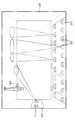
도 1은 본 발명의 일 실시예에 따른 구조체에 설치된 조명 시스템의 개략도이다.
도 2는 본 발명의 일 실시예에 따른 조명 시스템의 개략도이다.
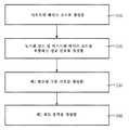
도 3은 본 발명의 일 실시예에 따른 조명 시스템의 휘도 출력에 데이터를 임베딩하는 방법 단계들의 흐름도이다.
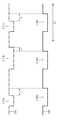
도 4는 본 발명의 일 실시예에 따른 구동 신호 및 변조된 구동 신호의 부분들의 개략도이다.
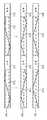
도 5는 본 발명의 일 실시예에 따른 상이한 광원들에 대한 정보 신호들의 개략도이다.
도 6a는 본 발명의 일 실시예에 따른 길이 13의 Barker 시퀀스의 자기 상관 결과들을 도시한다.
도 6b는 본 발명의 일 실시예에 따른 길이 31의 m-시퀀스의 주기적 자기 상관 결과들을 도시한다.
도 7은 본 발명의 일 실시예에 따른 광학 수신기의 개략도이다.1 is a schematic diagram of a lighting system installed in a structure according to an embodiment of the present invention.
2 is a schematic diagram of a lighting system according to an embodiment of the present invention.
3 is a flowchart of method steps for embedding data in a luminance output of a lighting system according to an embodiment of the invention.
4 is a schematic diagram of portions of a drive signal and a modulated drive signal according to an embodiment of the present invention.
5 is a schematic diagram of information signals for different light sources according to one embodiment of the invention.
6A illustrates autocorrelation results of a Barker sequence of length 13 in accordance with an embodiment of the present invention.
6B shows periodic autocorrelation results of an m-sequence of length 31 in accordance with an embodiment of the present invention.
7 is a schematic diagram of an optical receiver according to an embodiment of the present invention.
다음의 설명에서, 다수의 특정 세부사항들은 본 발명의 보다 철저한 이해를 제공하기 위해서 기재된다. 그러나, 본 발명이 이들 특정 세부사항들 중 하나 이상 없이 실시될 수 있다는 것은 당업자에게 명백할 것이다. 다른 경우에, 잘 알려진 특징들은 본 발명을 모호하게 하는 것을 회피하기 위해서 기술되지 않았다.In the following description, numerous specific details are set forth in order to provide a thorough understanding of the present invention. However, it will be apparent to those skilled in the art that the present invention may be practiced without one or more of these specific details. In other instances, well known features have not been described in order to avoid obscuring the present invention.
도 1은 조명 시스템(110)이 설치되어 있는 구조체(100)(이 경우에, 방)를 도시한다. 조명 시스템(110)은 하나 이상의 광원들(120) 및 광원들(120)을 제어하는 하나 이상의 제어기들(도 1에 도시되지 않음)을 포함한다. 광원들(120)은 고압/저압 가스 방전 소스들, 무기/유기 발광 다이오드들, 레이저 다이오드들, 백열 소스들 또는 할로겐 소스들을 포함할 수 있다. 조명 시스템(110)은 사용자가 광원들(120)을 제어할 수 있게 하는 리모트 컨트롤(130)을 더 포함할 수 있다.1 shows a structure 100 (in this case a room) in which the
도 2는 본 발명의 일 실시예에 따른 조명 시스템(200)의 개략도이다. 조명 시스템(200)은 도 1에 도시된 구조체(100)의 조명 시스템(110)으로서 이용될 수 있다. 도시된 바와 같이, 조명 시스템(200)은 적어도 시스템 제어기(210) 및 광원(220-1)을 포함하며, 광 설정들에 따라 휘도 출력(205)을 생성하도록 구성된다.2 is a schematic diagram of a
다른 실시예들에서, 조명 시스템은 부가적인 광원들 및 부가적인 광원들을 제어하는 부가적인 제어기들을 포함할 수 있다. 이러한 실시예들은 다양한 광원들을 제어하는 단일의 제어기(시스템 제어기(210))를 참조하여 본 명세서에서 기술될 것이다. 그러나, 당업자라면, 시스템 제어기(210)가 조명 시스템(200)에 포함된 광원들 각각에 대한 개별 제어기들을 포함할 수 있음을 인식할 것이다.In other embodiments, the lighting system may include additional light sources and additional controllers that control the additional light sources. These embodiments will be described herein with reference to a single controller (system controller 210) that controls various light sources. However, one of ordinary skill in the art will appreciate that
조명 시스템(200)은 다음과 같이 동작하도록 구성된다. 도 2에 도시된 바와 같이, 조명 시스템(200)에 대한 광 설정들은 구동 신호 생성기(230)(선택적으로, 조명 시스템(200) 내에 포함될 수 있음)에 제공된다. 광 설정들은, 평균 휘도 출력(205)이 예를 들어 광 파워(예를 들어, 루멘으로 정의됨) 및 컬러에 관하여 이루어져야 함을 나타낸다. 광 설정들은 리모트 컨트롤(130)을 통해 사용자에 의해 제공되거나, 또는 신 설정을 제어하는 외부 유닛으로부터 프로그래밍되며 제공될 수 있다. 대안으로, 광 설정들은 프로그래밍되어, 구동 신호 생성기(230) 내의 또는 조명 시스템(200) 내의 메모리에 저장될 수 있다. 구동 신호 생성기(230)는 조명 시스템(200) 내의 상이한 광원들에 대한 상이한 전기 구동 신호들로 광 설정들을 변환하며, 구동 신호들을 시스템 제어기(210)에 제공한다. 도 2에 예시된 실시예에서, 구동 신호 생성기(230)는 제1 광원(220-1)에 대한 제1 구동 신호로 광 설정들을 변환한다. 다음에, 시스템 제어기(210)는 각각의 구동 신호들로 상이한 광원들을 구동하여, 휘도 출력(205)을 생성한다. 도 2에 예시된 실시예에서, 시스템 제어기(210)는 제1 구동 신호로 광원(220-1)을 구동하여 휘도 출력(225-1)을 생성하도록 구성된다. 조명 시스템(200)의 휘도 출력(205)은 휘도 출력(225-1)을 포함한다.The
상술된 바와 같이, 광 설정들은, 조명 시스템(200)의 휘도 출력(205)이 예를 들어 광 컬러에 관하여 이루어져야 함을 나타낸다. 휘도 출력(205)의 컬러 변화는, 구동 신호 생성기(230)로부터 시스템 제어기(210)에 제공된 구동 신호들의 제어를 통해 조명 시스템(200) 내의 상이한 광원들(도 2에 도시되지 않은 부가적이며 선택적인 광원들)을 상이하게 디밍함으로써 달성될 수 있다. 광원마다 일정한 디밍 레벨을 위해, 구동 신호 생성기(230)로부터 시스템 제어기(210)에 제공되는 구동 신호는, 특정 프레임 주기로 반복되는 펄스들의 반복 패턴(본 명세서에서 "구동 패턴"으로 언급됨)을 포함한다.As described above, the light settings indicate that the
광원들을 디밍하는 다양한 방법들은 당업자에게 공지된 것이므로, 본 명세서에서는 상세하게 기술하지 않는다. 이들 방법들은 예를 들어 펄스 폭 변조, 펄스 밀도 변조 또는 진폭 변조를 포함한다.Various methods of dimming light sources are well known to those skilled in the art and are not described in detail herein. These methods include, for example, pulse width modulation, pulse density modulation or amplitude modulation.
시스템 제어기(210)는 데이터 소스(240)로부터 데이터 신호(245)를 수신하도록 또한 구성된다. 데이터 신호(245)는 데이터를 포함하고, 시스템 제어기(210)는 조명 시스템(200)의 휘도 출력(205)에 데이터를 임베딩하도록 구성된다. 데이터는, 예를 들어 조명 시스템(200), 광원(220-1)의 국부화된 ID, 그들의 성능들 및 현재의 광 설정들, 또는 조명 시스템(200)에 관련될 수 있는 다른 타입의 정보를 나타낼 수 있다. 후술되는 바와 같이, 시스템 제어기(210)는, 시프트된 베이스 코드 및 동기화 코드를 포함하는 정보 신호로 광원(220-1)에 적용된 구동 신호를 변조함으로써 데이터를 임베딩한다. 시프트된 베이스 코드를 생성하기 위해서 베이스 코드에 적용되는 주기적 위상 시프트는 휘도 출력(205)에 임베딩될 특정 데이터에 대응한다.
도 3은 본 발명의 일 실시예에 따른 조명 시스템(200)의 휘도 출력(205)에 데이터 신호(245)의 데이터의 적어도 일부를 임베딩하는 방법 단계들의 흐름도이다. 방법 단계들은 도 1 및 도 2와 관련하여 기술되지만, 당업자라면, 방법 단계들을 임의의 순서로 수행하도록 구성된 임의의 시스템이 본 발명의 범위 내에 있음을 인식할 것이다.3 is a flowchart of method steps for embedding at least a portion of the data of the data signal 245 in the
이 방법은 단계(310)에서 시작하는데, 여기서 시스템 제어기(210)는 시프트된 베이스 코드에 데이터를 임베딩하기 위해서 위상 시프트로 베이스 코드 기간 내의 베이스 코드를 주기적으로 시프트함으로써 시프트된 베이스 코드를 생성한다. 베이스 코드는 2개 이상의 이진 값들의 시퀀스이다. 상술된 바와 같이, "위상 시프트"라는 용어는 베이스 코드 기간 내의 베이스 코드와 시프트된 베이스 코드 사이의 시간 차를 언급하거나, 또는 대안으로 시프트된 베이스 코드가 베이스 코드에 대하여 시프트되는 이진 값들의 수를 언급한다. 위상 시프트는 시프트된 베이스 코드에 임베딩된 데이터에 대응한다.The method begins at
위상 시프트로 데이터를 임베딩하는 상이한 방식들이 존재하는 것에 유의한다. 제1의 가장 간단한 방법은 이진 변조를 이용하는 것이다. 이러한 경우에, 위상 시프트의 방향이 데이터를 결정한다. 예를 들어, 네거티브 시프트는 논리 "0"을 나타낼 수 있으며, 포지티브 시프트는 논리 "1"을 나타낼 수 있다. 대안으로, 변조는 멀티레벨일 수 있는데, 여기서 위상 시프트의 방향 및 크기 모두가 데이터를 결정한다. 예를 들어, 하나의 이진 값에 대한 네거티브 시프트는 논리 "00"을 나타낼 수 있고, 2개의 이진 값들에 대한 네거티브 시프트는 논리 "01"을 나타낼 수 있고, 하나의 이진 값에 대한 포지티브 시프트는 논리 "10"을 나타낼 수 있으며, 2개의 이진 값들에 대한 포지티브 시프트는 논리 "11"을 나타낼 수 있다. 따라서, 하나 이상의 데이터 심볼들은 각각의 베이스 코드 기간 내에 임베딩될 수 있다. 또한, 위상 시프트가 0인 경우에 데이터 심볼들이 임베딩될 수 있다는 것에 유의한다.Note that there are different ways of embedding data with phase shift. The first and simplest method is to use binary modulation. In this case, the direction of the phase shift determines the data. For example, a negative shift may represent a logic "0" and a positive shift may represent a logic "1". Alternatively, the modulation can be multilevel, where both the direction and magnitude of the phase shift determines the data. For example, a negative shift for one binary value may represent a logic "00", a negative shift for two binary values may represent a logic "01", and a positive shift for one binary value may be logical It may represent "10" and the positive shift for the two binary values may represent the logic "11". Thus, one or more data symbols may be embedded within each base code period. Also note that data symbols may be embedded when the phase shift is zero.
본 발명의 일 실시예에 따르면, 시프트된 베이스 코드에 임베딩된 데이터는 광원(220-1)의 ID를 포함할 수 있다. 이러한 실시예에서, 광원(220-1)은 예를 들어 1 단위의 위상 시프트와 연관됨으로써 식별될 수 있는데, 여기서 베이스 코드는 하나의 이진 값만큼 우측으로 주기적으로 시프트된다.According to an embodiment of the present invention, the data embedded in the shifted base code may include the ID of the light source 220-1. In this embodiment, the light source 220-1 may be identified, for example, by being associated with a phase shift of one unit, where the base code is periodically shifted to the right by one binary value.
단계(310)로부터, 이 방법은 단계(320)로 진행하는데, 여기서 시스템 제어기(210)는 시프트된 베이스 코드 및 동기화 코드를 포함하는 정보 신호를 생성한다. 베이스 코드와 유사하게, 동기화 코드도 또한 2개 이상의 이진 값들의 시퀀스이다. 베이스 코드는 조명 시스템(200)의 휘도 출력(205)에 데이터를 임베딩하는 역할을 하는 한편, 동기화 코드는 임베딩된 데이터를 검색하도록 구성된 광학 수신기에 대해 동기화를 제공하는 역할을 한다.From
다음에, 이 방법은 단계(330)로 진행하는데, 여기서 시스템 제어기(210)는 광원(220-1)에 대한 구동 신호를 변조함으로써 변조된 구동 신호를 생성한다. 시스템 제어기(210)는, 정보 신호의 시프트된 베이스 코드에 임베딩된 데이터가 변조된 구동 신호에 임베딩된 다음에, 조명 시스템(200)의 휘도 출력(205)에 임베딩될 수 있도록 정보 신호에 응답하여 구동 신호를 변조한다.Next, the method proceeds to step 330 where the
다양한 실시예들에서, 시스템 제어기(210)는, 예를 들어 펄스 폭 변조(PWM), 펄스 위치 변조, 펄스 밀도 변조 또는 진폭 변조를 이용하여 이진 또는 멀티레벨 변조를 통해 구동 신호를 변조함으로써 변조된 구동 신호를 생성할 수 있다. 예를 들어, PWM을 이용하여 정보 신호로부터 이진 값 0을 임베딩하기 위해서, 시스템 제어기(210)는 구동 신호 내의 구동 패턴을 a의 양만큼 더 좁게 하여 정보 신호로부터 이진 값 "0"을 임베딩할 수 있으며, 시스템 제어기(210)는 구동 신호 내의 다른 구동 패턴을 b의 양만큼 더 넓게 하여 정보 신호로부터 이진 값 "1"을 임베딩할 수 있다. 이는 도 4에 예시되어 있다. 도시된 바와 같이, 구동 신호(401)는 구동 패턴들(401-1, 401-2 및 401-3)로 도시된 3개의 구동 패턴들을 포함한다. 구동 패턴들(401-1 내지 401-3) 각각은 반복 주기 T2로 반복된다. 시스템 제어기(210)는, 신호(401)의 구동 패턴들(401-1 및 401-3)을 더 좁게 하여 신호(402)의 구동 패턴들(402-1 및 402-3)을 각각 생성하며, 신호(401)의 구동 패턴(401-2)을 더 넓게 하여 신호(402)의 구동 패턴(402-2)을 생성함으로써, 변조된 구동 신호(402)를 생성하여 "010"을 구동 신호(401)에 임베딩할 수 있다. a의 양과 b의 양 사이의 비율을 정보 코드에서의 1들의 수와 0들의 수 사이의 비율과 동일하게 함으로써, 조명 시스템의 휘도 출력에 데이터를 임베딩하는 것이 사람의 눈에는 보이지 않게 될 수 있는데, 그 이유는 변조된 구동 신호의 시간 평균이 오리지널 구동 신호의 시간 평균과 동일하게 유지되기 때문이다. 당업자라면, 조명 시스템의 휘도 출력에 데이터를 임베딩하기 위해서 정보 신호에 따라 구동 신호를 변조하는 다른 방법들을 인식할 것이다.In various embodiments,
이 방법은 단계(340)에서 종료하는데, 여기서 광원(220-1)은, 광원(220-1)에 대하여 시스템 제어기(210)에 의해 적용되는 변조된 구동 신호에 응답하여 휘도 출력(225-1)을 생성한다. 조명 시스템(200)의 휘도 출력(205)은 휘도 출력(225-1)을 포함한다.The method ends at
도 5는 본 발명의 일 실시예에 따른 3개의 상이한 광원들에 대한 정보 신호들(501, 502 및 503)의 개략도이다. 정보 신호들(501-503)은 베이스 코드들의 상이한 위상 시프트들로 임베딩된 상이한 데이터를 포함한다. 도시된 바와 같이, 정보 신호(501)는 동기화 코드(505) 및 시프트된 베이스 코드(510)의 교호 시퀀스를 포함한다. 유사하게, 정보 신호(502)는 동기화 코드(505) 및 시프트된 베이스 코드(520)의 교호 시퀀스를 포함하며, 정보 신호(503)는 동기화 코드(505) 및 시프트된 베이스 코드(530)의 교호 시퀀스를 포함한다. 정보 신호들(501-503)은 동일한 동기화 코드 및 동일한 베이스 코드를 포함하지만, 정보 신호들(501-503) 각각에 있어서, 베이스 코드는 상이한 위상 시프트로 주기적으로 시프트되어, 3개의 상이한 광원들의 휘도 출력들에 상이한 데이터를 임베딩한다.5 is a schematic diagram of information signals 501, 502 and 503 for three different light sources according to an embodiment of the invention. Information signals 501-503 contain different data embedded with different phase shifts of base codes. As shown, the information signal 501 includes an alternating sequence of
조명 시스템의 휘도 출력에 임베딩된 데이터가 예를 들어 광원들의 식별자들과 같은 몇몇 종류의 식별자들을 포함하는 경우, 이러한 방식으로 식별될 수 있는 상이한 광원들의 수는 베이스 코드의 길이에 종속한다. 따라서, 베이스 코드가 N개의 이진 값들을 포함하는 경우, 상이한 위상 시프트들로 베이스 코드들을 주기적으로 시프트함으로써 N개의 상이한 광원들이 식별될 수 있다.If the data embedded in the luminance output of the illumination system includes some kind of identifiers, for example identifiers of the light sources, the number of different light sources that can be identified in this way depends on the length of the base code. Thus, if the base code contains N binary values, N different light sources can be identified by periodically shifting the base codes with different phase shifts.
다른 실시예들에서, 데이터는 정보 신호 내의 시프트된 베이스 코드의 부호를 또한 설정함으로써 임베딩될 수 있다. 조명 시스템의 휘도 출력에 임베딩된 데이터가 광원들의 식별자들을 포함하며, 베이스 코드가 N개의 이진 값들을 포함하는 경우, 베이스 코드들의 부호를 설정하며 상이한 위상 시프트들로 이들 베이스 코드들을 주기적으로 시프트함으로써 2N개의 상이한 광원들이 식별될 수 있다.In other embodiments, data may be embedded by also setting the sign of the shifted base code in the information signal. If the data embedded in the luminance output of the lighting system contains identifiers of the light sources, and the base code contains N binary values, set the sign of the base codes and 2N by periodically shifting these base codes with different phase shifts. Different light sources can be identified.
또한, 정보 신호가 동기화 코드들 및 시프트된 베이스 코드들의 교호 시퀀스를 포함하는 경우, 정보 신호 내의 시프트된 베이스 코드의 상이한 인스턴스들의 부호들을 설정함으로써 휘도 출력(205)에 부가적인 데이터가 임베딩될 수 있다. 이러한 방식으로, 예를 들어 광원의 온도 또는 디밍 레벨에 관련된 부가적인 데이터가 광원의 휘도 출력에 임베딩될 수 있다.Furthermore, if the information signal includes an alternating sequence of synchronization codes and shifted base codes, additional data may be embedded in the
도 5에 예시된 실시예에서, 정보 신호들은 동기화 코드들 및 시프트된 베이스 코드들의 교호 시퀀스들을 포함하지만, 다른 실시예들에서, 정보 신호들은 하나의 동기화 코드와, 동기화 코드에 선행하거나 동기화 코드 다음의 2개 이상의 시프트된 베이스 코드들을 포함할 수 있다. 예를 들어, 정보 신호는 동기화 코드 및 3개의 시프트된 베이스 코드들의 교호 시퀀스를 포함할 수 있다. 정보 신호에서의 동기화 코드들의 발생을 감소시키면, 추가의 데이터를 임베딩할 수 있게 된다. 한편, 동기화 코드들의 발생을 증가시키면, 수신기측에서 더 쉽고 더 정확한 데이터 검색을 달성할 수 있게 되는데, 그 이유는 수신기가 반복되는 시프트된 베이스 코드들로부터 획득된 정보를 평균화할 수 있기 때문이다. 또 다른 실시예에서, 정보 신호는, 동기화 코드와 시프트된 베이스 코드 사이에 하나 이상의 이진 값들의 시퀀스(본 명세서에서 "스페이서 시퀀스"로 언급됨)를 더 포함할 수 있다. 예를 들어, 정보 신호는 동기화 코드와 시프트된 베이스 코드 사이에 15개의 0들의 스페이서 시퀀스를 포함할 수 있다. 이러한 스페이서 시퀀스를 삽입하면, 수신기측에서 임베딩된 데이터를 검색하는데 필요한 데이터 처리를 감소시키고/시키거나 단순화할 수 있으며, 수신기에서의 더 정확한 식별 또는 조명 기여도 추정(illumination contribution estimation)을 가능하게 할 수 있다. 조명 기여도 추정은 도 7에 더 상세하게 기술된다.In the embodiment illustrated in FIG. 5, the information signals include alternating sequences of synchronization codes and shifted base codes, but in other embodiments, the information signals precede one synchronization code and precede or follow the synchronization code. It may include two or more shifted base codes of. For example, the information signal may comprise an alternating sequence of synchronization code and three shifted base codes. Reducing the occurrence of synchronization codes in the information signal makes it possible to embed additional data. On the other hand, increasing the generation of synchronization codes makes it possible to achieve easier and more accurate data retrieval at the receiver side, since the receiver can average information obtained from repeated shifted base codes. In another embodiment, the information signal may further comprise a sequence of one or more binary values (referred to herein as "spacer sequences") between the synchronization code and the shifted base code. For example, the information signal may include a 15 sequence of spacers between the synchronization code and the shifted base code. Insertion of such spacer sequences can reduce and / or simplify the data processing required to retrieve embedded data at the receiver side, and allow for more accurate identification or illumination contribution estimation at the receiver. have. Illumination contribution estimation is described in more detail in FIG. 7.
바람직한 실시예에서, 동기화 코드는 양호한 자기 상관 특성들을 갖는 코드를 포함하는데, 이는, 정보 신호가 동기화 코드와 상관되는 경우, 상관 값이 코드의 시프트되지 않은 버전들에 대해서만 비교적 높으며 시프트된 버전들에 대해서는 상당히 더 낮을 것임을 의미한다. 이러한 코드의 일례는 Barker 시퀀스이며, 이는 2, 3, 4, 5, 7, 11 및 13의 길이들에 대해 존재한다. 길이 13의 Barker 시퀀스는 1 1 1 1 1 0 0 1 1 0 1 0 1을 포함한다. 이러한 시퀀스의 자기 상관 결과는 도 6a에 예시되어 있다.In a preferred embodiment, the synchronization code comprises a code having good autocorrelation characteristics, where the correlation value is relatively high only for unshifted versions of the code and if the information signal is correlated with the synchronization code, It will be considerably lower. One example of such code is a Barker sequence, which exists for lengths of 2, 3, 4, 5, 7, 11 and 13. A Barker sequence of length 13 contains 1 1 1 1 1 0 0 1 1 0 1 0 1. The autocorrelation results of this sequence are illustrated in FIG. 6A.
또한, 바람직한 실시예에서, 베이스 코드는 양호한 주기적 상관 특성들을 갖는 코드를 포함하는데, 이는, 동기화 코드와 상관된 정보 신호의 상관 출력에 기초하여, 정보 신호가 베이스 코드와 상관되는 경우, 상관 값이 코드의 (주기적으로) 시프트되지 않은 버전들에 대해서만 비교적 높은 한편, 모든 다른 주기적 시프트들에 대해서는 상관 값들이 상당히 더 작음을 의미한다. 이러한 코드의 예로는, 최대 길이 시퀀스("m-시퀀스"로도 언급됨), Gold 코드 또는 Kasami 시퀀스가 포함된다. 길이 31의 m-시퀀스는 0 0 0 0 1 0 1 0 1 1 1 0 1 1 0 0 0 1 1 1 1 1 0 0 1 1 0 1 0 0 1을 포함한다. 이러한 시퀀스의 주기적 자기 상관 결과는 도 6b에 예시되어 있다. m-시퀀스는 시스템 제어기(210) 내에 포함될 수 있는 선형 피드백 시프트 레지스터들을 이용하여 생성될 수 있다(레지스터들은 도 2에 도시되지 않음).Further, in a preferred embodiment, the base code comprises a code having good periodic correlation characteristics, which is based on the correlation output of the information signal correlated with the synchronization code, where the correlation value is correlated with the base code. Only relatively unshifted versions of the code are relatively high, whereas for all other periodic shifts the correlation values are significantly smaller. Examples of such codes include maximum length sequences (also referred to as "m-sequences"), gold codes, or Kasami sequences. An m-sequence of length 31 includes 0 0 0 0 1 0 1 0 1 1 1 0 1 1 0 0 0 1 1 1 1 1 0 0 1 1 0 1 0 0 1. Periodic autocorrelation results of this sequence are illustrated in FIG. 6B. The m-sequence may be generated using linear feedback shift registers that may be included in the system controller 210 (registers not shown in FIG. 2).
또한, 동기화 코드 및 베이스 코드는, 동기화 코드와 베이스 코드 사이의 상호 상관(cross correlation)이 낮도록 선택되어야 한다. 이러한 경우에, 동기화 코드, 베이스 코드, 및 베이스 코드에 적용된 위상 시프트는 수신기측에서 정확하게 검출될 수 있다.In addition, the synchronization code and the base code should be selected so that the cross correlation between the synchronization code and the base code is low. In this case, the synchronization code, base code, and phase shift applied to the base code can be detected accurately at the receiver side.
다시 도 2를 참조하면, 조명 시스템(200)은 적어도 제2 광원 및 제2 제어기(도 2에 도시되지 않음)를 선택적으로 더 포함할 수 있다. 상술된 모든 설명은 제2 광원 및 제2 제어기에 대해서도 유지된다. 일 실시예에서, 제2 제어기의 기능이 시스템 제어기(210)에 의해 수행된다고 가정하면, 2개의 상이한 광원들에 대해 동작하는 경우, 시스템 제어기(210)는 다음의 단계들을 수행하도록 구성된다.Referring again to FIG. 2, the
상술된 바와 같이, 시스템 제어기(210)는, 제1 시프트된 베이스 코드에 제1 데이터를 임베딩하기 위해서 베이스 코드 기간 내의 베이스 코드를 제1 위상 시프트로 주기적으로 시프트함으로써 제1 시프트된 베이스 코드를 생성하는데, 여기서 제1 위상 시프트는 제1 데이터에 대응한다. 또한, 시스템 제어기(210)는 제1 시프트된 베이스 코드 및 동기화 코드를 포함하는 제1 정보 신호를 생성하고, 제1 데이터가 조명 시스템의 휘도 출력에 임베딩되도록 제1 정보 신호에 따라 제1 구동 신호의 제1 구동 패턴들 중 하나 이상을 변조함으로써 제1 변조된 구동 신호를 생성한다. 또한, 유사하게, 시스템 제어기(210)는, 제2 데이터를 제2 시프트된 베이스 코드에 임베딩하기 위해서 베이스 코드 기간 내의 베이스 코드를 제2 위상 시프트로 주기적으로 시프트함으로써 제2 시프트된 베이스 코드를 생성하는데, 여기서 제2 위상 시프트는 제2 데이터에 대응한다. 또한, 시스템 제어기(210)는 제2 시프트된 베이스 코드 및 동기화 코드를 포함하는 제2 정보 신호를 생성하고, 제2 데이터가 조명 시스템의 휘도 출력에 임베딩되도록 제2 정보 신호에 따라 제2 구동 신호의 제2 구동 패턴들 중 하나 이상을 변조함으로써 제2 변조된 구동 신호를 생성한다. 제1 변조된 구동 신호에 응답하여, 제1 광원은 제1 휘도 출력을 생성하며, 제2 변조된 구동 신호에 응답하여, 제2 광원은 제2 휘도 출력을 생성한다. 이러한 실시예에서, 휘도 출력(205)은 제1 휘도 출력 및 제2 휘도 출력을 포함한다.As described above, the
조명 시스템(200) 내의 2개의 광원들은 동기 모드로 또는 비동기 모드로 동작할 수 있다. 동기 모드에서, 2개의 광원들에 대해 이용되는 정보 신호들의 동기화 코드들은 시간에 있어서 완전히 오버랩한다(즉, 제1 정보 신호의 동기화 코드들은 제2 정보 신호의 동기화 코드들과 동시에 시작함). 비동기 모드에서, 2개의 광원들의 동기화 코드들은 시간에 있어서 완전히 오버랩하지 않는다(즉, 제1 정보 신호의 동기화 코드들은 제2 정보 신호의 동기화 코드들과 상이한 시간에 시작함). 동기 또는 비동기 동작 모드에서, 동일한 동기화 코드들 및 동일한 베이스 코드들은 모든 광원들에 대해 이용될 수 있는데, 여기서 시스템 제어기(210)는 광원들 각각에 대한 베이스 코드에 고유한 주기적 시프트를 적용한다. 따라서, 데이터는 다른 광원들과 동기화하는 것을 요구하지 않고 광원들 각각에 의해 생성된 휘도 출력에 임베딩될 수 있다.The two light sources in the
도 7은 조명 시스템(200)과 함께 사용하도록 구성된 본 발명의 일 실시예에 따른 광학 수신기(700)의 개략도이다. 리모트 컨트롤(130) 내에 포함될 수 있는 광학 수신기(700)는 조명 시스템(200)의 휘도 출력(205)에 임베딩된 데이터 신호(245)의 데이터를 결정하도록 구성된다. 도시된 바와 같이, 광학 수신기(700)는 광학 검출기(710), 처리 유닛(720) 및 선택적으로 메모리(740)를 포함한다.7 is a schematic diagram of an
얼마나 많은 광원들이 조명 시스템(200) 내에 포함되는지 그리고 광원들이 동기로 동작하는지 또는 비동기로 동작하는지에 따라, 휘도 출력(205)으로부터 데이터를 검색하는 상이한 방법들이 광학 수신기(700)에 구현될 수 있다.Depending on how many light sources are included in the
광학 수신기(700)에 구현된 모든 방법들에 있어서, 처리 유닛(720)은 베이스 코드, 동기화 코드, 및 동기화 코드가 정보 신호들에서 얼마나 자주 발생하는지에 대한 정보에 액세스한다. 일 실시예에서, 데이터를 임베딩하기 위해서 시스템 제어기(210)가 베이스 코드의 위상 시프트를 시작하기 전에 또는 시스템 제어기(210)가 이러한 위상 시프트를 중지한 후에, 조명 시스템(200)은 이러한 정보를 처리 유닛(720)에 직접 제공할 수 있다. 다른 실시예에서, 광학 수신기(700)는 이러한 정보를 저장하는 메모리(740)를 포함할 수 있다. 또 다른 실시예에서, 광학 수신기(700)는 (무선으로) 수신된 광 신호들로부터 이러한 정보를 획득하도록 구성될 수 있다. 예를 들어, 조명 시스템(200)의 광원들 중 하나 이상은, 트레이닝 시간 기간의 지속기간 동안 시프트되지 않은 베이스 코드들을 포함하는 정보 신호들에 기초하여 생성되는 변조된 구동 신호들에 따라 각각의 휘도 출력들을 생성하도록 구성될 수 있다. 트레이닝 시간 기간 중에, 광학 수신기(700)는 베이스 코드, 동기화 코드, 및/또는 동기화 코드의 발생 빈도를 검출된 휘도 출력(205)으로부터 획득할 수 있는데, 그 이유는 그 시간 기간에 시스템 제어기(210)가 베이스 코드를 위상 시프트하지 않기 때문이다. 이러한 트레이닝 기간은 예를 들어 규칙적 패턴(예를 들어, 초당 한번)으로 발생하거나, 또는 새로운 수신기가 시스템에서 검출되는 경우에 발생할 수 있다. 수신된 광 신호들로부터 획득된 베이스 코드, 동기화 코드, 및/또는 동기화 코드의 발생 빈도는 나중 이용을 위해 메모리(740)에 저장될 수 있다. 대안으로, 처리 유닛(720)은, 상술된 수단 중 임의의 수단에 의해, 베이스 코드, 동기화 코드, 및/또는 동기화 코드의 발생 빈도 자체가 아니라, 그 파생물들(즉, 이러한 정보가 획득될 수 있는 파라미터들)을 획득할 수 있다. 예를 들어, 처리 유닛(720)은 Barker 시퀀스나 m-시퀀스의 길이 또는 가능한 베이스 코드들의 세트로부터의 하나를 참조하는 지시자 번호를 획득할 수 있다. 베이스 코드 및/또는 동기화 코드는 그 후 처리 유닛(720)에 의해 재생성될 수 있는데, 이는 광학 수신기(700)에 제공되는 통신의 양을 잠재적으로 감소시킨다. 다른 실시예에서, 베이스 코드 및/또는 동기화 코드를 기술하는 파라미터들은 수신된 광 신호들로부터 추출될 수 있다.In all the methods implemented in the
데이터를 검색하는 방법 단계들이 도 7과 관련하여 기술되었지만, 당업자라면, 방법 단계들을 임의의 순서로 수행하도록 구성된 임의의 시스템이 본 발명의 범위 내에 있음을 인식할 것이다.Although method steps for retrieving data have been described in connection with FIG. 7, those skilled in the art will recognize that any system configured to perform the method steps in any order is within the scope of the present invention.
광학 수신기(700)에 구현될 수 있는 제1 방법은, 조명 시스템(200)이 단일 광원을 포함하는 경우, 휘도 출력(205)으로부터 데이터를 검색하는 방법 단계들을 포함한다. 이 방법은 단계(1-1)에서 시작하는데, 여기서 광학 검출기(710)는 예를 들어 광 검출기, 컬러 센서, 광 검출기 어레이 또는 카메라와 같은 감광성 검출기를 통해 휘도 출력(205)을 검출한다. 이 실시예에서, 휘도 출력(205)은 조명 시스템(200)의 단일 광원의 휘도 출력을 포함한다. 단계(1-2)에서, 처리 유닛(720)은 검출된 휘도 출력에 기초하여 정보 신호를 검색한다. 이는, 예를 들어 정보 신호에 도달하도록 구동 신호로부터 컨디셔닝(증폭 및 필터링)되고, 디지털화되며 복조되는 전기 신호로 수신된 광학 신호(검출된 휘도 출력(205))를 변환함으로써 달성될 수 있다. 이러한 수신기 동작들은 당업자에게 공지되어 있다.A first method that can be implemented in the
단계(1-3)에서, 처리 유닛(720)은 정보 신호와 동기화 코드를 상관시킨다. 이러한 상관의 결과로서, 적어도 하나의 피크를 갖는 제1 상관 출력이 생성된다. 상술된 바와 같이, 상관 출력은 통상적으로 다수의 "피크들"을 포함하는데, 그 일부는 다른 피크들보다 더 작으며, 상관 프로세스의 아티팩트들을 나타낸다. 이러한 작은 피크들은 본 명세서에서 "서브피크들"로 언급되며, "피크"라는 용어는 정보 코드의 관련 부분들의 시작들(예를 들어, 동기화 코드의 시작 또는 베이스 코드의 시작)을 나타내는 상관 출력의 피크들을 기술하는데 이용된다. 이들 피크들은 상관 출력에서 서브피크들보다 명백히 더 높으며, 당업자는 이들을 쉽게 식별할 수 있다.In step 1-3, the
제1 상관 출력 내의 적어도 하나의 피크는 정보 신호 내의 동기화 코드의 시작에 대응한다. 시스템 제어기(210)에 의해 생성된 정보 신호가 동기화 코드 및 베이스 코드의 교호 시퀀스를 포함하는 경우, 제1 상관 출력은 정보 신호 내의 동기화 코드의 각각의 인스턴스에 대응하는 수개의 피크들을 갖는다.At least one peak in the first correlation output corresponds to the start of a synchronization code in the information signal. When the information signal generated by the
제1 상관 출력 내의 피크의 위치는 데이터를 임베딩하기 위해서 베이스 코드에 적용된 위상 시프트의 성공적인 결정에 필요한 동기화를 처리 유닛(720)에 제공한다. 처리 유닛(720)이 베이스 코드, 동기화 코드, 및 정보 신호에서의 동기화 코드의 발생 빈도에 액세스하기 때문에, 일단 처리 유닛(720)이 동기화 코드의 시작을 식별했으면, 처리 유닛(720)은 동기화 코드 다음의 또는 그 이전의 베이스 코드가 시프트되었는지와 얼마나 많이 시프트되었는지를 식별할 수 있다. 따라서, 단계(1-4)에서, 제1 상관 출력 내의 피크의 위치에 기초하여, 처리 유닛(720)은 정보 신호와 베이스 코드를 주기적으로 상관시켜, 하나의 피크를 갖는 제2 상관 출력을 생성한다. 이 피크는 정보 신호 내의 베이스 코드의 시작에 대응한다. 제2 상관 출력 내의 이 피크의 위치는 정보 신호에 존재하는 시프트된 베이스 코드를 생성하기 위해서 시스템 제어기(210)에 의해 베이스 코드에 적용된 위상 시프트에 의해 결정된다. 예를 들어, 시스템 제어기(210)가 5 단위만큼 베이스 코드를 위상 시프트함으로써 시프트된 베이스 코드를 생성한 경우, 제2 상관 출력은 5 단위에 대응하는 위치에서의 피크를 포함한다.The position of the peak in the first correlation output provides the
단계(1-5)에서, 제2 상관 출력 내의 피크의 위치에 기초하여, 처리 유닛(720)은 시프트된 베이스 코드를 생성하기 위해서 시스템 제어기(210)에 의해 베이스 코드에 적용된 위상 시프트를 결정한다. 이 방법은 단계(1-6)에서 종료하는데, 여기서 이 결정된 위상 시프트에 기초하여, 처리 유닛(720)은 시프트된 베이스 코드에 임베딩된 데이터를 결정한다.In steps 1-5, based on the position of the peak in the second correlation output, the
광학 수신기(700)에 구현될 수 있는 제2 방법은, 조명 시스템(200)이 2개의 동기 광원들을 포함하는 경우, 휘도 출력(205)으로부터 데이터를 검색하는 방법 단계들을 포함한다. 이 방법은 단계(2-1)에서 시작하는데, 여기서 광학 검출기(710)는 휘도 출력(205)을 검출한다. 역시, 휘도 출력(205)은 예를 들어 광 검출기, 컬러 센서, 광 검출기 어레이 또는 카메라와 같은 감광성 검출기를 통해 검출될 수 있다. 이 실시예에서, 휘도 출력(205)은 조명 시스템(200)의 2개의 광원들의 휘도 출력들의 합이다. 단계(2-2)에서, 처리 유닛(720)은 검출된 휘도 출력에 기초하여 전체 정보 신호를 검색한다. 이는 제1 방법에 기술된 바와 같이 달성될 수 있다. 전체 정보 신호는 하나의 광원에 대응하는 정보 신호와 다른 광원에 대응하는 정보 신호의 합이다.A second method that can be implemented in the
단계(2-3)에서, 처리 유닛(720)은 전체 정보 신호와 동기화 코드를 상관시킨다. 이러한 상관의 결과로서, 적어도 하나의 피크를 갖는 상관 출력이 생성된다. 2개의 광원들이 동기로 동작하기 때문에, 그들의 동기화 코드들은 시간에 있어서 오버랩하며, 피크는, 제1 정보 신호의 동기화 코드와 동시에 시작하는 제2 정보 신호 내의 동기화 코드와, 제1 정보 신호 내의 동기화 코드의 합에 대응한다. 역시, 상술된 바와 같이, 시스템 제어기(210)에 의해 생성된 제1 정보 신호 및 제2 정보 신호 각각이 동기화 코드 및 베이스 코드의 교호 시퀀스를 포함하는 경우, 제1 상관 출력은 전체 정보 신호 내의 오버랩 동기화 코드의 각각의 인스턴스에 대응하는 수개의 피크들을 갖는다.In step 2-3, the
상술된 단계(1-4)와 유사하게, 단계(2-4)에서, 제1 상관 출력 내의 피크의 위치에 기초하여, 처리 유닛(720)은 전체 정보 신호와 베이스 코드를 주기적으로 상관시켜, 제2 상관 출력을 생성한다. 이 경우, 제2 상관 출력은 2개의 피크들을 갖는다. 피크들은 전체 정보 신호 내의 2개의 상이한 베이스 코드들(제1 정보 신호 및 제2 정보 신호 각각으로부터 하나씩)에 대응한다. 2개의 피크들의 위치들은 2개의 광원들에 대한 정보 신호들을 생성하기 위해서 시스템 제어기(210)에 의해 베이스 코드에 적용된 위상 시프트들에 의해 결정된다. 따라서, 제2 상관 출력 내의 2개의 피크들 중 하나의 위치는, 전체 정보 신호에 존재하는 제1 시프트된 베이스 코드를 생성하기 위해서 시스템 제어기(210)에 의해 베이스 코드에 적용된 제1 위상 시프트에 의해 결정되며, 다른 피크의 위치는, 전체 정보 신호에 존재하는 제2 시프트된 베이스 코드를 생성하기 위해서 시스템 제어기(210)에 의해 베이스 코드에 적용된 제2 위상 시프트에 의해 결정된다. 예를 들어, 시스템 제어기(210)가 5 단위만큼 베이스 코드를 위상 시프트함으로써 제1 시프트된 베이스 코드를 생성하고, 2 단위만큼 베이스 코드를 위상 시프트함으로써 제2 시프트된 베이스 코드를 생성한 경우, 제2 상관 출력은 5 단위 및 2 단위에 대응하는 위치들에서의 피크들을 포함한다.Similar to step 1-4 described above, in step 2-4, based on the position of the peak in the first correlation output, the
단계(2-5)에서, 제2 상관 출력 내의 2개의 피크들 중 하나의 위치에 기초하여, 처리 유닛(720)은 시프트된 베이스 코드를 생성하기 위해서 시스템 제어기(210)에 의해 베이스 코드들 중 하나에 적용된 위상 시프트(예를 들어, 제1 위상 시프트)를 결정한다. 단계(2-6)에서, 이 결정된 제1 위상 시프트에 기초하여, 처리 유닛(720)은 제1 시프트된 베이스 코드에 임베딩된 데이터를 결정한다.In steps 2-5, based on the position of one of the two peaks in the second correlation output, the
단계(2-7)에서, 제2 상관 출력 내의 2개의 피크들 중 다른 하나의 위치에 기초하여, 처리 유닛(720)은 시프트된 베이스 코드를 생성하기 위해서 시스템 제어기(210)에 의해 다른 베이스 코드에 적용된 위상 시프트(예를 들어, 제2 위상 시프트)를 결정한다. 이 방법은 단계(2-8)에서 종료하는데, 여기서 이 결정된 제2 위상 시프트에 기초하여, 처리 유닛(720)은 제2 시프트된 베이스 코드에 임베딩된 데이터를 결정한다.In steps 2-7, based on the position of the other of the two peaks in the second correlation output, the
광학 수신기(700)에 구현될 수 있는 제3 방법은, 조명 시스템(200)이 2개의 비동기 광원들을 포함하는 경우, 휘도 출력(205)으로부터 데이터를 검색하는 방법 단계들을 포함한다. 이 방법은 단계(3-1)에서 시작하는데, 여기서 광학 검출기(710)는 휘도 출력(205)을 검출한다. 역시, 휘도 출력(205)은 예를 들어 광 검출기, 컬러 센서, 광 검출기 어레이 또는 카메라와 같은 감광성 검출기를 통해 검출될 수 있다. 이 실시예에서, 휘도 출력(205)은 조명 시스템(200)의 2개의 광원들의 휘도 출력들의 합이다. 단계(3-2)에서, 처리 유닛(720)은 검출된 휘도 출력에 기초하여 전체 정보 신호를 검색한다. 이는 제1 방법에 기술된 바와 같이 달성될 수 있다. 전체 정보 신호는 하나의 광원에 대응하는 정보 신호와 다른 광원에 대응하는 정보 신호의 합이다.A third method that may be implemented in the
단계(3-3)에서, 처리 유닛(720)은 전체 정보 신호와 동기화 코드를 상관시킨다. 이러한 상관의 결과로서, 적어도 2개의 피크들을 갖는 제1 상관 출력이 생성된다. 2개의 광원들이 비동기로 동작하기 때문에, 그들의 동기화 코드들은 시간에 있어서 오버랩하지 않으며, 따라서 피크들 중 하나는 제1 정보 신호 내의 동기화 코드의 시작에 대응하는 한편, 다른 피크는 제2 정보 신호 내의 동기화 코드의 시작에 대응한다. 역시, 상술된 바와 같이, 시스템 제어기(210)에 의해 생성된 제1 정보 신호 및 제2 정보 신호 각각이 동기화 코드 및 베이스 코드의 교호 시퀀스를 포함하는 경우, 제1 상관 출력은 전체 정보 신호 내의 동기화 코드의 각각의 인스턴스에 대응하는 수개의 피크들을 갖는다.In step 3-3, the
단계(3-4)에서, 제1 상관 출력 내의 최고 피크의 위치에 기초하여, 처리 유닛(720)은 전체 정보 신호와 베이스 코드를 주기적으로 상관시켜, 하나의 피크를 갖는 제2 상관 출력을 생성한다. 제1 상관 출력 내의 최고 피크는 조명 시스템(200)에 포함된 2개의 광원들 중 가장 강한 광원의 동기화 코드의 시작에 대응한다. 제1 광원이 가장 강한 광원이라고 가정하면, 제2 상관 출력 내의 최고 피크는 제1 광원에 대응하는 제1 정보 신호 내의 베이스 코드에 대응한다. 역시, 이러한 피크의 위치는, 제1 정보 신호를 생성하기 위해서 시스템 제어기(210)에 의해 베이스 코드에 적용된 제1 위상 시프트에 의해 결정된다. 예를 들어, 시스템 제어기(210)가 5 단위만큼 베이스 코드를 위상 시프트함으로써 제1 정보 신호의 제1 시프트된 베이스 코드를 생성한 경우, 제2 상관 출력은 5 단위에 대응하는 위치에서의 피크를 포함한다.In step 3-4, based on the position of the highest peak in the first correlation output, the
단계(3-5)에서, 제2 상관 출력 내의 피크의 위치에 기초하여, 처리 유닛(720)은 제1 시프트된 베이스 코드를 생성하기 위해서 시스템 제어기(210)에 의해 베이스 코드에 적용된 제1 위상 시프트를 결정한다. 단계(3-6)에서, 이 결정된 제1 위상 시프트에 기초하여, 처리 유닛(720)은 제1 시프트된 베이스 코드에 임베딩된 데이터를 결정한다.In step 3-5, based on the position of the peak in the second correlation output, the
단계(3-6) 이후에, 처리 유닛(720)은 선택적으로 제1 상관 출력 내의 적어도 2개의 피크들 중 최고 피크의 상관 값 및/또는 제2 상관 출력 내의 피크의 상관 값에 기초하여 제1 정보 신호의 진폭을 결정할 수 있다. 그 후, 제1 상관 출력 내의 적어도 2개의 피크들 중 최고 피크의 위치, 제2 상관 출력 내의 피크의 위치, 및 제1 정보 신호의 결정된 진폭에 기초하여, 처리 유닛(720)은 제1 정보 신호를 재생성할 수 있다. 또한, 처리 유닛(720)은 전체 정보 신호로부터 재생성된 제1 정보 신호를 감산하여, 새로운 정보 신호를 획득할 수 있다. 이 때, 처리 유닛(720)은 전체 정보 신호 대신에 새로운 정보 신호를 이용하여 단계(3-3) 내지 단계(3-6)를 반복하여, 제2 시프트된 베이스 코드에 임베딩된 데이터를 결정할 수 있다.After steps 3-6, the
광원들의 휘도 출력에 임베딩된 데이터가 광원들의 식별자들을 포함하는 경우, 처리 유닛(720)은 제1 상관 출력 또는 제2 상관 출력 내의 피크들의 상관 값들을 더 이용하여, 상이한 식별된 광원들의 조명 기여도들을 추정할 수 있다.If the data embedded in the luminance output of the light sources includes identifiers of the light sources, the
상술된 모든 3가지 방법들에 있어서, 처리 유닛(720)은, 조명 시스템의 휘도 출력에 임베딩된 부가적인 데이터를 결정하기 위해서 시프트된 베이스 코드들의 부호들을 또한 결정할 수 있다.In all three methods described above, the
본 발명의 하나의 이점은, 조명 시스템에서 개별 광원들의 완전 비동기 동작을 허용하는 방식으로 조명 시스템의 휘도 출력에 데이터가 임베딩될 수 있다는 점이다.One advantage of the present invention is that data can be embedded in the luminance output of the lighting system in a manner that allows full asynchronous operation of the individual light sources in the lighting system.
본 발명의 일 실시예는 컴퓨터 시스템과 함께 사용하기 위한 프로그램 제품으로서 구현될 수 있다. 프로그램 제품의 프로그램(들)은 실시예들(본 명세서에 기술된 방법들을 포함함)의 기능들을 정의하며, 각종 컴퓨터 판독가능 저장 매체에 포함될 수 있다. 예시적인 컴퓨터 판독가능 저장 매체는, (i) 정보가 영구적으로 저장되는 기록 불가능 저장 매체(예를 들어, CD-ROM 드라이브에 의해 판독가능한 CD-ROM 디스크들과 같은 컴퓨터 내의 판독 전용 메모리 장치들, 플래시 메모리, ROM 칩들 또는 임의의 타입의 고체 상태 비휘발성 반도체 메모리); 및 (ii) 변경가능한 정보가 저장되는 기록가능 저장 매체(예를 들어, 디스켓 드라이브 또는 하드디스크 드라이브 내의 플로피 디스크들 또는 임의의 타입의 고체 상태 랜덤 액세스 반도체 메모리)를 포함하지만, 이에 제한되지는 않는다.One embodiment of the invention may be implemented as a program product for use with a computer system. The program (s) of the program product define the functions of the embodiments (including the methods described herein) and may be included in various computer readable storage media. Exemplary computer readable storage media include (i) non-writable storage media in which information is stored permanently (e.g., read-only memory devices in a computer, such as CD-ROM disks readable by a CD-ROM drive, Flash memory, ROM chips or any type of solid state nonvolatile semiconductor memory); And (ii) recordable storage media (e.g., floppy disks in a diskette drive or hard disk drive or any type of solid state random access semiconductor memory) in which modifiable information is stored. .
전술한 내용은 본 발명의 실시예들에 관한 것이지만, 본 발명의 다른 그리고 추가 실시예들은 그 기본적인 범위로부터 벗어나지 않고 고안될 수 있다. 예를 들어, 본 발명의 양태들은 하드웨어나 소프트웨어로 또는 하드웨어와 소프트웨어의 조합으로 구현될 수 있다. 따라서, 본 발명의 범위는 다음의 특허청구범위에 의해 결정된다.While the foregoing is directed to embodiments of the invention, other and further embodiments of the invention may be devised without departing from the basic scope thereof. For example, aspects of the invention may be implemented in hardware or software or a combination of hardware and software. Accordingly, the scope of the invention is determined by the following claims.
Claims (15)
Translated fromKorean제1 데이터를 제1 시프트된 베이스 코드에 임베딩하기 위해서 베이스 코드 기간(base code period) 내의 베이스 코드를 제1 위상 시프트로 주기적으로 시프트함으로써 상기 제1 시프트된 베이스 코드를 생성하고 - 상기 제1 위상 시프트는 상기 제1 데이터에 대응함 -, 상기 제1 시프트된 베이스 코드 및 동기화 코드를 포함하는 제1 정보 신호를 생성하며, 상기 제1 데이터가 상기 조명 시스템의 휘도 출력에 임베딩되게 상기 제1 정보 신호에 따라 제1 구동 신호의 제1 구동 패턴들 중 하나 이상을 변조함으로써 제1 변조된 구동 신호를 생성하도록 구성된 제1 제어기; 및
상기 제1 변조된 구동 신호에 따라 제1 휘도 출력을 생성하도록 구성된 제1 광원
을 포함하며,
상기 조명 시스템의 휘도 출력은 상기 제1 휘도 출력을 포함하는 조명 시스템.Lighting system, wherein the lighting system is for embedding data in the luminance output of the lighting system.
Generate the first shifted base code by periodically shifting a base code within a base code period to a first phase shift to embed first data in a first shifted base code-the first phase The shift corresponds to the first data, generating a first information signal comprising the first shifted base code and a synchronization code, the first information signal being embedded in the luminance output of the lighting system A first controller configured to generate a first modulated drive signal by modulating one or more of the first drive patterns of the first drive signal according to; And
A first light source configured to generate a first luminance output in accordance with the first modulated drive signal
Including;
The brightness output of the lighting system comprises the first brightness output.
상기 제1 데이터는 상기 제1 광원의 ID(identification)를 포함하는 조명 시스템.The method of claim 1,
And the first data comprises an identification of the first light source.
상기 제1 제어기는, 상기 베이스 코드 기간 내의 상기 제1 시프트된 베이스 코드의 부호를 설정함으로써 상기 제1 시프트된 베이스 코드를 생성하도록 또한 구성되는 조명 시스템.The method of claim 1,
The first controller is further configured to generate the first shifted base code by setting a sign of the first shifted base code within the base code period.
상기 동기화 코드는 2개 이상의 이진 값들의 제1 시퀀스를 포함하고, 상기 제1 시퀀스는 상관을 이용하여 검출가능하고, 상기 베이스 코드는 2개 이상의 이진 값들의 제2 시퀀스를 포함하고, 상기 제2 시퀀스는 주기적 상관(cyclic correlation)을 이용하여 검출가능하며, 그리고/또는 상기 동기화 코드와 상기 베이스 코드 사이의 상호 상관(cross-correlation)은 낮은 조명 시스템.The method of claim 1,
The synchronization code includes a first sequence of two or more binary values, the first sequence is detectable using correlation, the base code comprises a second sequence of two or more binary values, and the second The sequence is detectable using cyclic correlation, and / or the cross-correlation between the synchronization code and the base code is low.
상기 제1 제어기는, 상기 제1 시프트된 베이스 코드 및 제2 시프트된 베이스 코드에 부가적인 데이터를 임베딩하기 위해서, 상기 베이스 코드 기간 내의 상기 제1 시프트된 베이스 코드의 제1 부호를 설정함으로써 상기 제1 시프트된 베이스 코드를 생성하고, 상기 베이스 코드 기간 내의 상기 베이스 코드를 상기 제1 위상 시프트로 주기적으로 시프트하며 상기 제2 시프트된 베이스 코드의 제2 부호를 설정함으로써 상기 제2 시프트된 베이스 코드를 생성하도록 또한 구성되며,
상기 제1 정보 신호는 상기 제2 시프트된 베이스 코드를 더 포함하는 조명 시스템.The method of claim 1,
The first controller is configured to set the first code of the first shifted base code within the base code period to embed additional data in the first shifted base code and the second shifted base code. Generate the second shifted base code, periodically shift the base code within the base code period to the first phase shift, and set a second code of the second shifted base code to set the second shifted base code; It is also configured to generate,
And the first information signal further comprises the second shifted base code.
제2 데이터를 제2 시프트된 베이스 코드에 임베딩하기 위해서 상기 베이스 코드 기간 내의 상기 베이스 코드를 제2 위상 시프트로 주기적으로 시프트함으로써 상기 제2 시프트된 베이스 코드를 생성하고 - 상기 제2 위상 시프트는 상기 제2 데이터에 대응함 -, 상기 제2 시프트된 베이스 코드 및 상기 동기화 코드를 포함하는 제2 정보 신호를 생성하며, 상기 제2 데이터가 상기 조명 시스템의 휘도 출력에 임베딩되게 상기 제2 정보 신호에 따라 제2 구동 신호의 제2 구동 패턴들 중 하나 이상을 변조함으로써 제2 변조된 구동 신호를 생성하도록 구성된 제2 제어기; 및
상기 제2 변조된 구동 신호에 따라 제2 휘도 출력을 생성하도록 구성된 제2 광원
을 더 포함하며,
상기 조명 시스템의 휘도 출력은 상기 제2 휘도 출력을 더 포함하는 조명 시스템.The method of claim 1,
Generate the second shifted base code by periodically shifting the base code within the base code period to a second phase shift to embed second data in a second shifted base code, the second phase shift being the Corresponding to second data, generating a second information signal comprising the second shifted base code and the synchronization code, wherein the second data is embedded in the luminance output of the lighting system according to the second information signal; A second controller configured to generate a second modulated drive signal by modulating one or more of the second drive patterns of the second drive signal; And
A second light source configured to generate a second luminance output according to the second modulated drive signal
More,
The brightness output of the lighting system further comprises the second brightness output.
상기 제1 휘도 출력을 검출하도록 구성된 광학 검출기; 및
상기 베이스 코드 및 상기 동기화 코드에 액세스하는 처리 유닛
을 포함하며,
상기 처리 유닛은,
상기 검출된 제1 휘도 출력에 기초하여, 상기 제1 정보 신호를 검색하고,
상기 제1 정보 신호와 상기 동기화 코드를 상관시켜, 적어도 하나의 피크를 갖는 제1 상관 출력을 생성하고,
상기 제1 상관 출력 내의 상기 적어도 하나의 피크의 위치에 기초하여, 상기 제1 정보 신호와 상기 베이스 코드를 주기적으로 상관시켜, 하나의 피크를 갖는 제2 상관 출력을 생성하고,
상기 제2 상관 출력 내의 상기 하나의 피크의 위치에 기초하여, 상기 제1 위상 시프트를 결정하며,
상기 결정된 제1 위상 시프트에 기초하여, 상기 제1 데이터를 결정하도록 구성되는 광학 수신기.An optical receiver configured for use with a lighting system according to claim 1,
An optical detector configured to detect the first luminance output; And
A processing unit for accessing the base code and the synchronization code
Including;
The processing unit,
Based on the detected first luminance output, retrieve the first information signal,
Correlating the first information signal with the synchronization code to produce a first correlation output having at least one peak,
Based on the position of the at least one peak in the first correlation output, periodically correlating the first information signal with the base code to produce a second correlation output having one peak,
Based on the position of the one peak in the second correlation output, determine the first phase shift,
And based on the determined first phase shift, determine the first data.
상기 휘도 출력을 검출하도록 구성된 광학 검출기; 및
상기 베이스 코드 및 상기 동기화 코드에 액세스하는 처리 유닛
을 포함하며,
상기 처리 유닛은,
상기 검출된 휘도 출력에 기초하여, 전체 정보 신호를 검색하고 - 상기 전체 정보 신호는 상기 제1 정보 신호와 상기 제2 정보 신호의 합을 포함함 -,
상기 전체 정보 신호와 상기 동기화 코드를 상관시켜, 적어도 하나의 피크를 갖는 제1 상관 출력을 생성하고,
상기 제1 상관 출력 내의 상기 적어도 하나의 피크의 위치에 기초하여, 상기 전체 정보 신호와 상기 베이스 코드를 주기적으로 상관시켜, 2개의 피크들을 갖는 제2 상관 출력을 생성하고,
상기 제2 상관 출력 내의 상기 2개의 피크들 중 하나의 피크의 위치에 기초하여, 상기 제1 위상 시프트를 결정하고,
상기 제2 상관 출력 내의 상기 2개의 피크들 중 다른 하나의 피크의 위치에 기초하여, 상기 제2 위상 시프트를 결정하고,
상기 결정된 제1 위상 시프트에 기초하여, 상기 제1 데이터를 결정하며,
상기 결정된 제2 위상 시프트에 기초하여, 상기 제2 데이터를 결정하도록 구성되는 광학 수신기.An optical receiver configured for use with an illumination system according to claim 6, wherein the synchronization code of the first information signal and the synchronization code of the second information signal start simultaneously.
An optical detector configured to detect the luminance output; And
A processing unit for accessing the base code and the synchronization code
Including;
The processing unit,
Retrieve a full information signal based on the detected luminance output, the full information signal comprising a sum of the first information signal and the second information signal;
Correlating the entire information signal with the synchronization code to produce a first correlation output having at least one peak,
Based on the position of the at least one peak in the first correlation output, periodically correlating the entire information signal with the base code to produce a second correlation output having two peaks,
Based on the position of one of the two peaks in the second correlation output, determine the first phase shift,
Based on the position of the other of the two peaks in the second correlation output, determine the second phase shift,
Based on the determined first phase shift, determine the first data,
And based on the determined second phase shift, determine the second data.
상기 휘도 출력을 검출하도록 구성된 광학 검출기; 및
상기 베이스 코드 및 상기 동기화 코드에 액세스하는 처리 유닛
을 포함하며,
상기 처리 유닛은,
상기 검출된 휘도 출력에 기초하여, 전체 정보 신호를 검색하고 - 상기 전체 정보 신호는 상기 제1 정보 신호와 상기 제2 정보 신호의 합을 포함함 -,
상기 전체 정보 신호와 상기 동기화 코드를 상관시켜, 적어도 2개의 피크들을 갖는 제1 상관 출력을 생성하고,
상기 제1 상관 출력 내의 상기 적어도 2개의 피크들 중 최고 피크의 위치에 기초하여, 상기 전체 정보 신호와 상기 베이스 코드를 주기적으로 상관시켜, 하나의 피크를 갖는 제2 상관 출력을 생성하고,
상기 제2 상관 출력 내의 상기 하나의 피크의 위치에 기초하여, 상기 제1 위상 시프트를 결정하며,
상기 결정된 제1 위상 시프트에 기초하여, 상기 제1 데이터를 결정하도록 구성되는 광학 수신기.An optical receiver configured for use with a lighting system according to claim 6,
An optical detector configured to detect the luminance output; And
A processing unit for accessing the base code and the synchronization code
Including;
The processing unit,
Retrieve a full information signal based on the detected luminance output, the full information signal comprising a sum of the first information signal and the second information signal;
Correlating the full information signal with the synchronization code to produce a first correlation output having at least two peaks,
Based on the position of the highest peak of the at least two peaks in the first correlation output, periodically correlating the base information code with the base code to produce a second correlation output having one peak,
Based on the position of the one peak in the second correlation output, determine the first phase shift,
And based on the determined first phase shift, determine the first data.
상기 처리 유닛은,
상기 제1 상관 출력 내의 상기 적어도 2개의 피크들 중 최고 피크의 상관 값 및 상기 제2 상관 출력 내의 상기 하나의 피크의 상관 값 중 적어도 하나에 기초하여, 상기 제1 정보 신호의 진폭을 결정하고,
상기 제1 상관 출력 내의 상기 적어도 2개의 피크들 중 최고 피크의 위치, 상기 제2 상관 출력 내의 상기 하나의 피크의 위치, 및 상기 제1 정보 신호의 결정된 진폭에 기초하여, 상기 제1 정보 신호를 획득하고,
상기 전체 정보 신호로부터 상기 제1 정보 신호를 감산하여, 새로운 정보 신호를 획득하고,
상기 새로운 정보 신호와 상기 동기화 코드를 상관시켜, 적어도 하나의 피크를 갖는 제3 상관 출력을 생성하고,
상기 제3 상관 출력 내의 상기 적어도 하나의 피크의 최고 피크의 위치에 기초하여, 상기 새로운 정보 신호와 상기 베이스 코드를 주기적으로 상관시켜, 하나의 피크를 갖는 제4 상관 출력을 생성하고,
상기 제4 상관 출력 내의 상기 하나의 피크의 위치에 기초하여, 상기 제2 위상 시프트를 결정하며,
상기 결정된 제2 위상 시프트에 기초하여, 상기 제2 데이터를 결정하도록 또한 구성되는 광학 수신기.10. The method of claim 9,
The processing unit,
Determine an amplitude of the first information signal based on at least one of a correlation value of the highest peak of the at least two peaks in the first correlation output and a correlation value of the one peak in the second correlation output,
Based on the position of the highest peak of the at least two peaks in the first correlation output, the position of the one peak in the second correlation output, and the determined amplitude of the first information signal, Earned,
Subtract the first information signal from the entire information signal to obtain a new information signal,
Correlating the new information signal with the synchronization code to produce a third correlation output having at least one peak,
Based on the position of the highest peak of the at least one peak in the third correlation output, periodically correlating the new information signal with the base code to produce a fourth correlation output with one peak,
Based on the position of the one peak in the fourth correlation output, determine the second phase shift,
Based on the determined second phase shift, further configured to determine the second data.
상기 처리 유닛은 상기 제1 시프트된 베이스 코드의 부호를 결정하도록 또한 구성되는 광학 수신기.The method according to any one of claims 7 to 10,
The processing unit is further configured to determine a sign of the first shifted base code.
제7항 내지 제11항 중 어느 한 항에 따른 적어도 하나의 광학 수신기를 포함하는 리모트 컨트롤
을 포함하며,
상기 하나 이상의 조명 시스템들은 상기 리모트 컨트롤을 사용하여 제어되도록 구성되는 조명 구조체.One or more lighting systems according to claim 1; And
Remote control comprising at least one optical receiver according to any one of claims 7 to 11.
Including;
The one or more lighting systems are configured to be controlled using the remote control.
제1 데이터를 제1 시프트된 베이스 코드에 임베딩하기 위해서, 베이스 코드 기간 내의 베이스 코드를 제1 위상 시프트로 주기적으로 시프트함으로써 상기 제1 시프트된 베이스 코드를 생성하는 단계 - 상기 제1 위상 시프트는 상기 제1 데이터에 대응함 -;
상기 제1 시프트된 베이스 코드 및 동기화 코드를 포함하는 제1 정보 신호를 생성하는 단계;
상기 제1 데이터가 상기 조명 시스템의 휘도 출력에 임베딩되도록 상기 제1 정보 신호에 따라 제1 구동 신호의 제1 구동 패턴들 중 하나 이상을 변조함으로써 제1 변조된 구동 신호를 생성하는 단계; 및
상기 제1 변조된 구동 신호에 따라 제1 휘도 출력을 생성하는 단계
를 포함하며,
상기 조명 시스템의 휘도 출력은 상기 제1 휘도 출력을 포함하는 방법.A method of embedding data in the luminance output of a lighting system,
Generating the first shifted base code by periodically shifting a base code within a base code period to a first phase shift to embed first data in the first shifted base code, the first phase shift being the Corresponding to the first data;
Generating a first information signal comprising the first shifted base code and a synchronization code;
Generating a first modulated drive signal by modulating one or more of the first drive patterns of a first drive signal according to the first information signal such that the first data is embedded in the luminance output of the illumination system; And
Generating a first luminance output according to the first modulated drive signal
Including;
The luminance output of the lighting system comprises the first luminance output.
상기 검출된 휘도 출력에 기초하여, 전체 정보 신호를 검색하는 단계 - 상기 전체 정보 신호는 상기 제1 정보 신호와 상기 제2 정보 신호의 합을 포함함 -;
상기 전체 정보 신호와 상기 동기화 코드를 상관시켜, 적어도 하나의 피크를 갖는 제1 상관 출력을 생성하는 단계;
상기 제1 상관 출력 내의 상기 적어도 하나의 피크의 위치에 기초하여, 상기 전체 정보 신호와 상기 베이스 코드를 주기적으로 상관시켜, 2개의 피크들을 갖는 제2 상관 출력을 생성하는 단계;
상기 제2 상관 출력 내의 상기 2개의 피크들 중 하나의 피크의 위치에 기초하여, 상기 제1 위상 시프트를 결정하는 단계;
상기 제2 상관 출력 내의 상기 2개의 피크들 중 다른 하나의 피크의 위치에 기초하여, 상기 제2 위상 시프트를 결정하는 단계;
상기 결정된 제1 위상 시프트에 기초하여, 상기 제1 데이터를 결정하는 단계; 및
상기 결정된 제2 위상 시프트에 기초하여, 상기 제2 데이터를 결정하는 단계
를 수행하도록 구성된 소프트웨어 코드 부분들을 포함하는 컴퓨터 프로그램.When executed in an optical receiver according to claim 8,
Retrieving a full information signal based on the detected luminance output, wherein the full information signal includes a sum of the first information signal and the second information signal;
Correlating the entire information signal with the synchronization code to produce a first correlation output having at least one peak;
Periodically correlating the entire information signal with the base code based on a position of the at least one peak in the first correlation output to produce a second correlation output having two peaks;
Determining the first phase shift based on a position of one of the two peaks in the second correlation output;
Determining the second phase shift based on the position of the other of the two peaks in the second correlation output;
Determining the first data based on the determined first phase shift; And
Based on the determined second phase shift, determining the second data
A computer program comprising software code portions configured to perform a.
상기 검출된 휘도 출력에 기초하여, 전체 정보 신호를 검색하는 단계 - 상기 전체 정보 신호는 상기 제1 정보 신호와 상기 제2 정보 신호의 합을 포함함 -;
상기 전체 정보 신호와 상기 동기화 코드를 상관시켜, 적어도 2개의 피크들을 갖는 제1 상관 출력을 생성하는 단계;
상기 제1 상관 출력 내의 상기 적어도 2개의 피크들 중 최고 피크의 위치에 기초하여, 상기 전체 정보 신호와 상기 베이스 코드를 주기적으로 상관시켜, 하나의 피크를 갖는 제2 상관 출력을 생성하는 단계;
상기 제2 상관 출력 내의 상기 하나의 피크의 위치에 기초하여, 상기 제1 위상 시프트를 결정하는 단계; 및
상기 결정된 제1 위상 시프트에 기초하여, 상기 제1 데이터를 결정하는 단계
를 수행하도록 구성된 소프트웨어 코드 부분들을 포함하는 컴퓨터 프로그램.When executed in an optical receiver according to claim 9,
Retrieving a full information signal based on the detected luminance output, wherein the full information signal includes a sum of the first information signal and the second information signal;
Correlating the entire information signal with the synchronization code to produce a first correlation output having at least two peaks;
Periodically correlating the entire information signal with the base code based on a position of the highest peak of the at least two peaks in the first correlation output to produce a second correlation output having one peak;
Determining the first phase shift based on the position of the one peak in the second correlation output; And
Based on the determined first phase shift, determining the first data
A computer program comprising software code portions configured to perform a.
Applications Claiming Priority (2)
| Application Number | Priority Date | Filing Date | Title |
|---|---|---|---|
| EP09164498.9 | 2009-07-03 | ||
| EP09164498 | 2009-07-03 |
Publications (1)
| Publication Number | Publication Date |
|---|---|
| KR20120038467Atrue KR20120038467A (en) | 2012-04-23 |
Family
ID=43304629
Family Applications (1)
| Application Number | Title | Priority Date | Filing Date |
|---|---|---|---|
| KR1020127002942AWithdrawnKR20120038467A (en) | 2009-07-03 | 2010-06-30 | Method and system for asynchronous lamp identification |
Country Status (8)
| Country | Link |
|---|---|
| US (1) | US8737842B2 (en) |
| EP (1) | EP2449858B1 (en) |
| JP (1) | JP2012532412A (en) |
| KR (1) | KR20120038467A (en) |
| CN (1) | CN102474943B (en) |
| BR (1) | BRPI1010189A2 (en) |
| RU (1) | RU2012103598A (en) |
| WO (1) | WO2011001392A2 (en) |
Families Citing this family (20)
| Publication number | Priority date | Publication date | Assignee | Title |
|---|---|---|---|---|
| KR20120038467A (en)* | 2009-07-03 | 2012-04-23 | 코닌클리즈케 필립스 일렉트로닉스 엔.브이. | Method and system for asynchronous lamp identification |
| CN102783134B (en)* | 2010-03-09 | 2015-08-12 | 松下电器产业株式会社 | Camera device and information detection method |
| EP2742776B1 (en) | 2011-08-08 | 2021-05-26 | Quarkstar LLC | Dimmable lighting devices and methods for dimming same |
| WO2013074065A1 (en) | 2011-11-14 | 2013-05-23 | Intel Corporation | Methods and arrangements for frequency shift communications by undersampling |
| CN104041190B (en) | 2012-01-17 | 2017-01-18 | 皇家飞利浦有限公司 | Lighting device and Lighting System using plurality of different modulation periods |
| US8861976B2 (en)* | 2012-06-29 | 2014-10-14 | Intel Corporation | Transmit and receive MIMO protocols for light array communications |
| US9148250B2 (en) | 2012-06-30 | 2015-09-29 | Intel Corporation | Methods and arrangements for error correction in decoding data from an electromagnetic radiator |
| US9218532B2 (en) | 2012-09-28 | 2015-12-22 | Intel Corporation | Light ID error detection and correction for light receiver position determination |
| US9178615B2 (en) | 2012-09-28 | 2015-11-03 | Intel Corporation | Multiphase sampling of modulated light with phase synchronization field |
| US9590728B2 (en) | 2012-09-29 | 2017-03-07 | Intel Corporation | Integrated photogrammetric light communications positioning and inertial navigation system positioning |
| EP2940896B1 (en)* | 2012-12-27 | 2020-04-08 | Panasonic Intellectual Property Corporation of America | Information communication method |
| US9496955B2 (en)* | 2013-09-19 | 2016-11-15 | eocys, LLC | Devices and methods to produce and receive an encoded light signature |
| US9735868B2 (en)* | 2014-07-23 | 2017-08-15 | Qualcomm Incorporated | Derivation of an identifier encoded in a visible light communication signal |
| US9832338B2 (en) | 2015-03-06 | 2017-11-28 | Intel Corporation | Conveyance of hidden image data between output panel and digital camera |
| US10456685B2 (en)* | 2015-04-14 | 2019-10-29 | Nintendo Co., Ltd. | Identifying and tracking objects via lighting patterns |
| US10368414B2 (en) | 2015-05-26 | 2019-07-30 | Signify Holding B.V. | Determining the position of a portable device relative to a luminaire |
| EP3488667A1 (en)* | 2016-07-21 | 2019-05-29 | Signify Holding B.V. | Lamp with coded light functionality |
| US10505628B2 (en)* | 2017-09-29 | 2019-12-10 | OSRAM SYLVNAIA Inc. | Designated map luminaires |
| US20190109640A1 (en)* | 2017-10-10 | 2019-04-11 | General Electric Company | Method and system for commissioning a lighting system |
| US10117316B1 (en)* | 2017-10-13 | 2018-10-30 | Osram Sylvania Inc. | Rotating identifications in light-based positioning systems |
Family Cites Families (47)
| Publication number | Priority date | Publication date | Assignee | Title |
|---|---|---|---|---|
| US4779266A (en)* | 1986-03-10 | 1988-10-18 | Bell Communications Research, Inc. | Encoding and decoding for code division multiple access communication systems |
| ATE133821T1 (en)* | 1989-04-18 | 1996-02-15 | Ilid Pty Ltd | DATA TRANSMISSION SYSTEM |
| US5424859A (en)* | 1992-09-24 | 1995-06-13 | Nippon Telegraph And Telephone Corp. | Transceiver for wireless in-building communication sytem |
| GB9321535D0 (en)* | 1993-10-19 | 1993-12-08 | Bsc Developments Ltd | Signalling techniques |
| US5838116A (en)* | 1996-04-15 | 1998-11-17 | Jrs Technology, Inc. | Fluorescent light ballast with information transmission circuitry |
| US5838472A (en)* | 1996-07-03 | 1998-11-17 | Spectrix Corporation | Method and apparatus for locating a transmitter of a diffuse infrared signal within an enclosed area |
| US20050169643A1 (en)* | 1997-01-02 | 2005-08-04 | Franklin Philip G. | Method and apparatus for the zonal transmission of data using building lighting fixtures |
| US6504633B1 (en)* | 1998-04-15 | 2003-01-07 | Talking Lights | Analog and digital electronic receivers for dual-use wireless data networks |
| US6426599B1 (en)* | 1999-04-14 | 2002-07-30 | Talking Lights, Llc | Dual-use electronic transceiver set for wireless data networks |
| US6400482B1 (en)* | 1998-04-15 | 2002-06-04 | Talking Lights, Llc | Communication system |
| US6198230B1 (en)* | 1998-04-15 | 2001-03-06 | Talking Lights | Dual-use electronic transceiver set for wireless data networks |
| US6794831B2 (en)* | 1998-04-15 | 2004-09-21 | Talking Lights Llc | Non-flickering illumination based communication |
| AU3568199A (en)* | 1998-04-15 | 1999-11-01 | Talking Lights Llc | Analog and digital electronic tranceivers for dual-use wireless data networks |
| JP2000106286A (en)* | 1998-09-28 | 2000-04-11 | Iwasaki Electric Co Ltd | Road lighting lamp non-lighting detection device |
| AU2001285408A1 (en)* | 2000-08-07 | 2002-02-18 | Color Kinetics Incorporated | Automatic configuration systems and methods for lighting and other applications |
| US8188878B2 (en)* | 2000-11-15 | 2012-05-29 | Federal Law Enforcement Development Services, Inc. | LED light communication system |
| US6574268B1 (en)* | 2000-11-21 | 2003-06-03 | Bbnt Solutions Llc | Asymmetric orthogonal codes for optical communications |
| US6542270B2 (en)* | 2000-12-08 | 2003-04-01 | Motorola, Inc. | Interference-robust coded-modulation scheme for optical communications and method for modulating illumination for optical communications |
| US6560471B1 (en)* | 2001-01-02 | 2003-05-06 | Therasense, Inc. | Analyte monitoring device and methods of use |
| US6865347B2 (en)* | 2001-01-05 | 2005-03-08 | Motorola, Inc. | Optically-based location system and method for determining a location at a structure |
| US6609840B2 (en)* | 2001-04-05 | 2003-08-26 | Alan Y. Chow | Wave length associative addressing system for WDM type light packet steering |
| US6519275B2 (en)* | 2001-06-29 | 2003-02-11 | Motorola, Inc. | Communications system employing differential orthogonal modulation |
| US7120205B2 (en)* | 2002-01-15 | 2006-10-10 | Jawad Ahmed Salehi | Method and system for multiple-shift code acquisition of optical orthogonal codes in optical CDMA systems |
| JP2004297593A (en)* | 2003-03-27 | 2004-10-21 | Mitsubishi Electric Corp | Spreading code generation method, spreading code generation device, and communication method |
| US7689130B2 (en)* | 2005-01-25 | 2010-03-30 | Koninklijke Philips Electronics N.V. | Method and apparatus for illumination and communication |
| US8045599B2 (en)* | 2005-02-17 | 2011-10-25 | Sony Corporation | Selection of training sequences for multiple-in multiple-out transmissions |
| JP2006229638A (en)* | 2005-02-18 | 2006-08-31 | Yokogawa Electric Corp | Time synchronization system |
| US7623042B2 (en)* | 2005-03-14 | 2009-11-24 | Regents Of The University Of California | Wireless network control for building lighting system |
| JP5091114B2 (en)* | 2005-04-22 | 2012-12-05 | コーニンクレッカ フィリップス エレクトロニクス エヌ ヴィ | Lighting control |
| JP4616714B2 (en)* | 2005-07-05 | 2011-01-19 | アバゴ・テクノロジーズ・ジェネラル・アイピー(シンガポール)プライベート・リミテッド | OPTICAL COMMUNICATION SYSTEM, LIGHTING DEVICE USED FOR THE SAME, AND TERMINAL DEVICE |
| WO2008154736A1 (en)* | 2007-06-18 | 2008-12-24 | Leddartech Inc. | Lighting system with driver assistance capabilities |
| EP2016807A4 (en)* | 2006-04-21 | 2011-02-16 | Koninkl Philips Electronics Nv | Method and apparatus for light intensity control |
| JP4988827B2 (en)* | 2006-05-03 | 2012-08-01 | コーニンクレッカ フィリップス エレクトロニクス エヌ ヴィ | Lighting copy and paste operations using lightwave identification |
| EP2039029B1 (en)* | 2006-06-28 | 2010-03-31 | Koninklijke Philips Electronics N.V. | Method and device for modulating the light emission of a lighting device |
| CN101132663B (en)* | 2006-08-21 | 2010-12-08 | 徐佳义 | Addressable demarcation repeater of electric lighting zone control system |
| CN101536371B (en)* | 2006-11-03 | 2013-01-02 | 皇家飞利浦电子股份有限公司 | Receiver for a modulated light signal and method for receiving a modulated light signal |
| EP1986322B1 (en)* | 2007-04-24 | 2012-11-14 | Eberspächer Controls GmbH & Co. KG | Semiconductor switch with integrated delay circuit |
| KR101368166B1 (en)* | 2007-07-09 | 2014-03-03 | 삼성전자주식회사 | Re-connection method in peripheral interface using visible light communication |
| DE102008009180A1 (en) | 2007-07-10 | 2009-01-22 | Sick Ag | Optoelectronic sensor |
| US8253353B2 (en)* | 2007-07-16 | 2012-08-28 | Koninklijke Philips Electronics N.V. | Driving a light source |
| ATE490674T1 (en)* | 2007-07-18 | 2010-12-15 | Koninkl Philips Electronics Nv | METHOD FOR PROCESSING LIGHT IN A STRUCTURE AND LIGHTING SYSTEM |
| US8488971B2 (en)* | 2007-07-19 | 2013-07-16 | Koninklijke Philips N.V. | Method, system and device for transmitting lighting device data |
| WO2009047693A2 (en)* | 2007-10-12 | 2009-04-16 | Koninklijke Philips Electronics N.V. | Sensing coded light using retro reflectors |
| EP2274958B1 (en) | 2008-05-06 | 2017-09-13 | Philips Lighting Holding B.V. | Illumination system and method for processing light |
| US8811300B2 (en)* | 2008-12-31 | 2014-08-19 | Mediatek Inc. | Physical structure and sequence design of midamble in OFDMA systems |
| US8165472B2 (en)* | 2009-02-19 | 2012-04-24 | Kabushiki Kaisha Toshiba | Apparatus for transmitting and receiving a signal in a visible light communication system |
| KR20120038467A (en)* | 2009-07-03 | 2012-04-23 | 코닌클리즈케 필립스 일렉트로닉스 엔.브이. | Method and system for asynchronous lamp identification |
- 2010
- 2010-06-30KRKR1020127002942Apatent/KR20120038467A/ennot_activeWithdrawn
- 2010-06-30RURU2012103598/07Apatent/RU2012103598A/ennot_activeApplication Discontinuation
- 2010-06-30EPEP10740315.6Apatent/EP2449858B1/ennot_activeNot-in-force
- 2010-06-30USUS13/381,982patent/US8737842B2/ennot_activeExpired - Fee Related
- 2010-06-30JPJP2012516969Apatent/JP2012532412A/enactivePending
- 2010-06-30BRBRPI1010189Apatent/BRPI1010189A2/ennot_activeApplication Discontinuation
- 2010-06-30CNCN201080030118.9Apatent/CN102474943B/ennot_activeExpired - Fee Related
- 2010-06-30WOPCT/IB2010/052998patent/WO2011001392A2/enactiveApplication Filing
Also Published As
| Publication number | Publication date |
|---|---|
| BRPI1010189A2 (en) | 2016-03-29 |
| WO2011001392A2 (en) | 2011-01-06 |
| EP2449858B1 (en) | 2013-06-05 |
| EP2449858A2 (en) | 2012-05-09 |
| JP2012532412A (en) | 2012-12-13 |
| US20120170939A1 (en) | 2012-07-05 |
| US8737842B2 (en) | 2014-05-27 |
| CN102474943B (en) | 2014-09-17 |
| WO2011001392A3 (en) | 2011-03-17 |
| RU2012103598A (en) | 2013-08-10 |
| CN102474943A (en) | 2012-05-23 |
Similar Documents
| Publication | Publication Date | Title |
|---|---|---|
| CN102474943B (en) | Method and system for asynchronous lamp identification | |
| JP5698764B2 (en) | Data detection for visible light communication using conventional camera sensors | |
| JP5698763B2 (en) | Method and system for 2D detection of local illumination contributions | |
| US9042738B2 (en) | Illumination device and method for embedding data symbols in a luminance output | |
| RU2538102C2 (en) | Effective address assignment in coded lighting systems | |
| US8660436B2 (en) | Coded light transmission and reception | |
| JP5475798B2 (en) | Illumination apparatus and method for embedding a data signal in a luminance output using an AC drive light source | |
| JP5384355B2 (en) | Light source with controlled color and method for controlling color generation in a light source | |
| CN101479966A (en) | Method and device for modulating the light emission of a lighting device | |
| CN104904319A (en) | Enabling a user to control coded light sources | |
| WO2015165749A1 (en) | Phase-modulated coded light |
Legal Events
| Date | Code | Title | Description |
|---|---|---|---|
| PA0105 | International application | St.27 status event code:A-0-1-A10-A15-nap-PA0105 | |
| PG1501 | Laying open of application | St.27 status event code:A-1-1-Q10-Q12-nap-PG1501 | |
| R18-X000 | Changes to party contact information recorded | St.27 status event code:A-3-3-R10-R18-oth-X000 | |
| PC1203 | Withdrawal of no request for examination | St.27 status event code:N-1-6-B10-B12-nap-PC1203 | |
| WITN | Application deemed withdrawn, e.g. because no request for examination was filed or no examination fee was paid | ||
| P22-X000 | Classification modified | St.27 status event code:A-2-2-P10-P22-nap-X000 | |
| P22-X000 | Classification modified | St.27 status event code:A-2-2-P10-P22-nap-X000 | |
| R18-X000 | Changes to party contact information recorded | St.27 status event code:A-3-3-R10-R18-oth-X000 | |
| P22-X000 | Classification modified | St.27 status event code:A-2-2-P10-P22-nap-X000 |