KR20120038457A - Lancet device with lance retraction - Google Patents
Lancet device with lance retractionDownload PDFInfo
- Publication number
- KR20120038457A KR20120038457AKR1020127002246AKR20127002246AKR20120038457AKR 20120038457 AKR20120038457 AKR 20120038457AKR 1020127002246 AKR1020127002246 AKR 1020127002246AKR 20127002246 AKR20127002246 AKR 20127002246AKR 20120038457 AKR20120038457 AKR 20120038457A
- Authority
- KR
- South Korea
- Prior art keywords
- needle holder
- slider
- hollow housing
- needle
- lancet
- Prior art date
- Legal status (The legal status is an assumption and is not a legal conclusion. Google has not performed a legal analysis and makes no representation as to the accuracy of the status listed.)
- Granted
Links
- 238000000034methodMethods0.000claimsdescription17
- 239000000853adhesiveSubstances0.000claimsdescription5
- 230000001070adhesive effectEffects0.000claimsdescription5
- 238000003466weldingMethods0.000claimsdescription2
- 230000033001locomotionEffects0.000description21
- 239000008280bloodSubstances0.000description10
- 210000004369bloodAnatomy0.000description10
- 238000000926separation methodMethods0.000description9
- 238000005381potential energyMethods0.000description8
- 230000000295complement effectEffects0.000description6
- 230000008878couplingEffects0.000description5
- 238000010168coupling processMethods0.000description5
- 238000005859coupling reactionMethods0.000description5
- 238000010304firingMethods0.000description5
- 230000013011matingEffects0.000description5
- 210000003811fingerAnatomy0.000description4
- 239000000463materialSubstances0.000description4
- 230000008901benefitEffects0.000description3
- 230000006378damageEffects0.000description3
- 201000010099diseaseDiseases0.000description3
- 208000037265diseases, disorders, signs and symptomsDiseases0.000description3
- 238000005304joiningMethods0.000description3
- 238000012986modificationMethods0.000description3
- 230000004048modificationEffects0.000description3
- 239000004033plasticSubstances0.000description3
- 230000001960triggered effectEffects0.000description3
- 240000007643Phytolacca americanaSpecies0.000description2
- 230000006835compressionEffects0.000description2
- 238000007906compressionMethods0.000description2
- 238000013461designMethods0.000description2
- 230000003993interactionEffects0.000description2
- 239000002184metalSubstances0.000description2
- 230000000284resting effectEffects0.000description2
- 208000012260Accidental injuryDiseases0.000description1
- 208000027418Wounds and injuryDiseases0.000description1
- 230000006978adaptationEffects0.000description1
- 238000007792additionMethods0.000description1
- 230000004323axial lengthEffects0.000description1
- 238000009534blood testMethods0.000description1
- 239000002131composite materialSubstances0.000description1
- 238000010276constructionMethods0.000description1
- 239000000356contaminantSubstances0.000description1
- 238000005520cutting processMethods0.000description1
- 238000005034decorationMethods0.000description1
- 206010012601diabetes mellitusDiseases0.000description1
- 238000001746injection mouldingMethods0.000description1
- 208000014674injuryDiseases0.000description1
- 238000012423maintenanceMethods0.000description1
- 238000004519manufacturing processMethods0.000description1
- 230000005541medical transmissionEffects0.000description1
- 239000002991molded plasticSubstances0.000description1
- 238000000465mouldingMethods0.000description1
- 230000000149penetrating effectEffects0.000description1
- 230000008092positive effectEffects0.000description1
- 238000003825pressingMethods0.000description1
- 230000001012protectorEffects0.000description1
- 239000012858resilient materialSubstances0.000description1
- 230000000717retained effectEffects0.000description1
- 229910001220stainless steelInorganic materials0.000description1
- 239000010935stainless steelSubstances0.000description1
- 238000012360testing methodMethods0.000description1
- 210000003813thumbAnatomy0.000description1
- 230000001052transient effectEffects0.000description1
Images


Classifications
- A—HUMAN NECESSITIES
- A61—MEDICAL OR VETERINARY SCIENCE; HYGIENE
- A61B—DIAGNOSIS; SURGERY; IDENTIFICATION
- A61B5/00—Measuring for diagnostic purposes; Identification of persons
- A61B5/14—Devices for taking samples of blood ; Measuring characteristics of blood in vivo, e.g. gas concentration within the blood, pH-value of blood
- A61B5/1405—Devices for taking blood samples
- A61B5/1411—Devices for taking blood samples by percutaneous method, e.g. by lancet
- A—HUMAN NECESSITIES
- A61—MEDICAL OR VETERINARY SCIENCE; HYGIENE
- A61B—DIAGNOSIS; SURGERY; IDENTIFICATION
- A61B5/00—Measuring for diagnostic purposes; Identification of persons
- A61B5/15—Devices for taking samples of blood
- A61B5/150007—Details
- A61B5/150015—Source of blood
- A61B5/150022—Source of blood for capillary blood or interstitial fluid
- A—HUMAN NECESSITIES
- A61—MEDICAL OR VETERINARY SCIENCE; HYGIENE
- A61B—DIAGNOSIS; SURGERY; IDENTIFICATION
- A61B5/00—Measuring for diagnostic purposes; Identification of persons
- A61B5/15—Devices for taking samples of blood
- A61B5/150007—Details
- A61B5/150374—Details of piercing elements or protective means for preventing accidental injuries by such piercing elements
- A61B5/150381—Design of piercing elements
- A61B5/150412—Pointed piercing elements, e.g. needles, lancets for piercing the skin
- A—HUMAN NECESSITIES
- A61—MEDICAL OR VETERINARY SCIENCE; HYGIENE
- A61B—DIAGNOSIS; SURGERY; IDENTIFICATION
- A61B5/00—Measuring for diagnostic purposes; Identification of persons
- A61B5/15—Devices for taking samples of blood
- A61B5/150007—Details
- A61B5/150374—Details of piercing elements or protective means for preventing accidental injuries by such piercing elements
- A61B5/150381—Design of piercing elements
- A61B5/150503—Single-ended needles
- A—HUMAN NECESSITIES
- A61—MEDICAL OR VETERINARY SCIENCE; HYGIENE
- A61B—DIAGNOSIS; SURGERY; IDENTIFICATION
- A61B5/00—Measuring for diagnostic purposes; Identification of persons
- A61B5/15—Devices for taking samples of blood
- A61B5/150007—Details
- A61B5/150374—Details of piercing elements or protective means for preventing accidental injuries by such piercing elements
- A61B5/150534—Design of protective means for piercing elements for preventing accidental needle sticks, e.g. shields, caps, protectors, axially extensible sleeves, pivotable protective sleeves
- A61B5/150541—Breakable protectors, e.g. caps, shields or sleeves, i.e. protectors separated destructively, e.g. by breaking a connecting area
- A—HUMAN NECESSITIES
- A61—MEDICAL OR VETERINARY SCIENCE; HYGIENE
- A61B—DIAGNOSIS; SURGERY; IDENTIFICATION
- A61B5/00—Measuring for diagnostic purposes; Identification of persons
- A61B5/15—Devices for taking samples of blood
- A61B5/150007—Details
- A61B5/150885—Preventing re-use
- A61B5/150893—Preventing re-use by indicating if used, tampered with, unsterile or defective
- A—HUMAN NECESSITIES
- A61—MEDICAL OR VETERINARY SCIENCE; HYGIENE
- A61B—DIAGNOSIS; SURGERY; IDENTIFICATION
- A61B5/00—Measuring for diagnostic purposes; Identification of persons
- A61B5/15—Devices for taking samples of blood
- A61B5/151—Devices specially adapted for taking samples of capillary blood, e.g. by lancets, needles or blades
- A61B5/15101—Details
- A61B5/15103—Piercing procedure
- A61B5/15107—Piercing being assisted by a triggering mechanism
- A61B5/15111—Semi-automatically triggered, e.g. at the end of the cocking procedure, for instance by biasing the main drive spring or when reaching sufficient contact pressure, the piercing device is automatically triggered without any deliberate action by the user
- A—HUMAN NECESSITIES
- A61—MEDICAL OR VETERINARY SCIENCE; HYGIENE
- A61B—DIAGNOSIS; SURGERY; IDENTIFICATION
- A61B5/00—Measuring for diagnostic purposes; Identification of persons
- A61B5/15—Devices for taking samples of blood
- A61B5/151—Devices specially adapted for taking samples of capillary blood, e.g. by lancets, needles or blades
- A61B5/15101—Details
- A61B5/15115—Driving means for propelling the piercing element to pierce the skin, e.g. comprising mechanisms based on shape memory alloys, magnetism, solenoids, piezoelectric effect, biased elements, resilient elements, vacuum or compressed fluids
- A61B5/15117—Driving means for propelling the piercing element to pierce the skin, e.g. comprising mechanisms based on shape memory alloys, magnetism, solenoids, piezoelectric effect, biased elements, resilient elements, vacuum or compressed fluids comprising biased elements, resilient elements or a spring, e.g. a helical spring, leaf spring, or elastic strap
- A—HUMAN NECESSITIES
- A61—MEDICAL OR VETERINARY SCIENCE; HYGIENE
- A61B—DIAGNOSIS; SURGERY; IDENTIFICATION
- A61B5/00—Measuring for diagnostic purposes; Identification of persons
- A61B5/15—Devices for taking samples of blood
- A61B5/151—Devices specially adapted for taking samples of capillary blood, e.g. by lancets, needles or blades
- A61B5/15101—Details
- A61B5/15126—Means for controlling the lancing movement, e.g. 2D- or 3D-shaped elements, tooth-shaped elements or sliding guides
- A61B5/15128—Means for controlling the lancing movement, e.g. 2D- or 3D-shaped elements, tooth-shaped elements or sliding guides comprising 2D- or 3D-shaped elements, e.g. cams, curved guide rails or threads
- A—HUMAN NECESSITIES
- A61—MEDICAL OR VETERINARY SCIENCE; HYGIENE
- A61B—DIAGNOSIS; SURGERY; IDENTIFICATION
- A61B5/00—Measuring for diagnostic purposes; Identification of persons
- A61B5/15—Devices for taking samples of blood
- A61B5/151—Devices specially adapted for taking samples of capillary blood, e.g. by lancets, needles or blades
- A61B5/15101—Details
- A61B5/15126—Means for controlling the lancing movement, e.g. 2D- or 3D-shaped elements, tooth-shaped elements or sliding guides
- A61B5/1513—Means for controlling the lancing movement, e.g. 2D- or 3D-shaped elements, tooth-shaped elements or sliding guides comprising linear sliding guides
- A—HUMAN NECESSITIES
- A61—MEDICAL OR VETERINARY SCIENCE; HYGIENE
- A61B—DIAGNOSIS; SURGERY; IDENTIFICATION
- A61B5/00—Measuring for diagnostic purposes; Identification of persons
- A61B5/15—Devices for taking samples of blood
- A61B5/151—Devices specially adapted for taking samples of capillary blood, e.g. by lancets, needles or blades
- A61B5/15134—Bladeless capillary blood sampling devices, i.e. devices for perforating the skin in order to obtain a blood sample but not using a blade, needle, canula, or lancet, e.g. by laser perforation, suction or pressurized fluids
- A—HUMAN NECESSITIES
- A61—MEDICAL OR VETERINARY SCIENCE; HYGIENE
- A61B—DIAGNOSIS; SURGERY; IDENTIFICATION
- A61B5/00—Measuring for diagnostic purposes; Identification of persons
- A61B5/15—Devices for taking samples of blood
- A61B5/151—Devices specially adapted for taking samples of capillary blood, e.g. by lancets, needles or blades
- A61B5/15142—Devices intended for single use, i.e. disposable
- A61B5/15144—Devices intended for single use, i.e. disposable comprising driving means, e.g. a spring, for retracting the piercing unit into the housing
- A—HUMAN NECESSITIES
- A61—MEDICAL OR VETERINARY SCIENCE; HYGIENE
- A61M—DEVICES FOR INTRODUCING MEDIA INTO, OR ONTO, THE BODY; DEVICES FOR TRANSDUCING BODY MEDIA OR FOR TAKING MEDIA FROM THE BODY; DEVICES FOR PRODUCING OR ENDING SLEEP OR STUPOR
- A61M5/00—Devices for bringing media into the body in a subcutaneous, intra-vascular or intramuscular way; Accessories therefor, e.g. filling or cleaning devices, arm-rests
- A61M5/178—Syringes
- A61M5/31—Details
- A61M5/32—Needles; Details of needles pertaining to their connection with syringe or hub; Accessories for bringing the needle into, or holding the needle on, the body; Devices for protection of needles
- A61M5/3202—Devices for protection of the needle before use, e.g. caps
Landscapes
- Health & Medical Sciences (AREA)
- Life Sciences & Earth Sciences (AREA)
- Animal Behavior & Ethology (AREA)
- Hematology (AREA)
- Veterinary Medicine (AREA)
- Public Health (AREA)
- Engineering & Computer Science (AREA)
- Biomedical Technology (AREA)
- Heart & Thoracic Surgery (AREA)
- General Health & Medical Sciences (AREA)
- Pathology (AREA)
- Surgery (AREA)
- Molecular Biology (AREA)
- Medical Informatics (AREA)
- Biophysics (AREA)
- Physics & Mathematics (AREA)
- Dermatology (AREA)
- Vascular Medicine (AREA)
- Anesthesiology (AREA)
- Measurement Of The Respiration, Hearing Ability, Form, And Blood Characteristics Of Living Organisms (AREA)
Abstract
Translated fromKoreanDescription
Translated fromKorean본 발명은 일반적으로 환자에게서 혈액 샘플을 채취하는데 사용되는 란셋 장치에 관한 것으로, 보다 구체적으로는, 환자의 피부나 조직과 접촉해 작동되는 란셋 장치에 관한 것이다.FIELD OF THE INVENTION The present invention generally relates to lancet devices used to take blood samples from a patient, and more particularly to lancet devices that operate in contact with the skin or tissue of a patient.
일반적으로 란셋 장치는 환자의 피부를 찔러 그 환자로부터 혈액 샘플을 얻기 위해 의료 시설에서 또한 개인에 의해 사용되고 있다. 이 란셋 장치는 단지 소량의 혈액만 필요할 때 사용된다. 당뇨병과 같은 질병의 경우에는, 환자의 혈당 레벨을 모니터링하기 위해 규칙적으로 혈액 시험을 하게 된다. 혈액 샘플을 얻을 때는 보통 손가락이나 몸의 다른 적절한 부위를 바늘로 찌르게 된다. 혈액을 통한 질병을 감안하여, 란셋의 사용 후에는 다른 사람이 그 란셋에 접촉하지 않는 것이 중요하다. 따라서, 란셋 장치의 중요한 일면은, 환자의 피부가 찔린 후에 바늘 이 다른 사람을 상처내는 것을 방지하는 것과 관련된다. 다른 사람에게 우발적인 상처를 주는 것을 막기 위해 란셋 장치의 사용 후에 란셋은 보호되어야 한다. 또한, 란셋은 장치가 다른 사람에게 사용됨으로 인한 질병 전염의 가능성을 줄이기 위해 쓰고 버릴 수 있는 것이어야 한다. 이와 관련하여, 란셋은 바람직하게는 재사용을 방지하는 요소를 갖는 일회용 장치이어야 한다.Lancet devices are generally used in medical facilities and also by individuals to pierce the skin of a patient to obtain blood samples from the patient. This lancet device is used when only a small amount of blood is needed. In diseases such as diabetes, blood tests are routinely performed to monitor the patient's blood sugar levels. When you get a blood sample, you usually poke a finger or other appropriate part of your body with a needle. Given the disease through the blood, it is important that no one contacts the lancet after use of the lancet. Thus, an important aspect of the lancet device involves preventing the needle from injuring another person after the patient's skin is stabbed. The lancet should be protected after use of the lancet device to prevent accidental injury to others. In addition, the lancet should be something that can be used and discarded to reduce the likelihood of disease transmission due to the device being used by others. In this regard, the lancet should preferably be a disposable device with elements to prevent reuse.
테오(Teo)에게 허여된 US 6,432,120 B1에는 접촉 작동식 란셋이 개시되어 있다. 이 장치는 바늘 홀더 및 란셋 구조체를 내장하는 촉발기(촉발 장치)를 갖는다. 촉발기는 촉발 요소를 통해 바늘 홀더와 상호 작용하게 되는데, 이 촉발 요소는 란셋 구조체가 조립체에의 우발적인 충돌에 의해 쉽게 촉발되지 않는 안정적인 대기 위치에 있도록 스프링을 압축 상태로 유지시킨다. 상기 장치는 압축된 상태에서 스프링과 결합된다. 테오에게 허여된 특허에 개시되어 있는 것과 같은 란셋은 환자에게 사용전에 미리 사용 준비된다. 미리 사용 준비된 란셋의 경우에는, 환자의 피부에 가해지기 전에 촉발되어 장치가 사용불가능하게 될 가능성이 있다.Contact operated lancets are disclosed in US Pat. No. 6,432,120 B1 to Te. The device has a trigger (trigger device) containing a needle holder and a lancet structure. The triggering device interacts with the needle holder through the triggering element, which keeps the spring in a compressed position so that the lancet structure is in a stable standby position that is not easily triggered by accidental collision with the assembly. The device is engaged with the spring in a compressed state. Lancets, such as those disclosed in the patent granted to Theo, are prepared for use before use in a patient. In the case of lancets that are ready for use, there is a possibility that they will be triggered before being applied to the patient's skin, making the device unusable.
Karbowniczek 등에게 허여된 WO 2005/110227 A1에는 하우징 구조체내에 있는 찌르기 요소를 갖는 란셋 구조체를 포함하는 접촉 작동식 란셋이 개시되어 있다. 이 장치는 란셋 구조체와 간섭 결합하는 회전축 레버 및 구동 스프링을 포함한다. 하우징내의 액츄에이터는 레버를 회전시켜, 란셋 구조체를 하우징의 후방 단부쪽으로 이동시켜 상기 구동 스프링을 적어도 부분적으로 압축시키고 그리 하여 란셋 구조체와의 간섭 결합에서 레버를 풀어주어 란셋 구조체가 앞쪽으로 나아갈 수 있게 된다. Karbowniczek 등에게 허여된 상기 특허는 란셋 구조체를 유지하고 풀어주기 위한 복잡한 장치를 개시하고 있으며 제작과 조립이 어렵다.WO 2005/110227 A1 to Karbowniczek et al. Discloses a contact actuated lancet comprising a lancet structure having a stab element in the housing structure. The device includes a rotational shaft lever and a drive spring for coherently coupling with the lancet structure. An actuator in the housing rotates the lever to move the lancet structure towards the rear end of the housing, thereby at least partially compressing the drive spring, thereby releasing the lever in the interference coupling with the lancet structure so that the lancet structure can move forward. . The patent, issued to Karbowniczek et al, discloses a complex device for holding and releasing a lancet structure and is difficult to manufacture and assemble.
사용전에 랜스 촉발의 가능성을 효과적으로 줄여주는 간단한 구성의 튼튼한 일회용 란셋 장치를 제공하는 것이 바람직하다.It is desirable to provide a sturdy disposable lancet device of simple construction that effectively reduces the likelihood of lance triggering before use.
제 1 양태에 따르면, 란셋 장치는, 공동부를 형성하고 근위 단부와 원위 단부를 갖는 중공 하우징을 포함한다. 본 란셋 장치는, 적어도 부분적으로 중공 하우징의 공동부내에서 종축선을 따라 외측 위치에서 밀린 위치까지 슬라이딩할 수 있는 슬라이더를 또한 포함한다. 이 슬라이더는 외측 위치에 있을 때 중공 하우징의 근위 단부를 넘어 공동부의 외부로 연장한다. 상기 란셋 장치는 랜스를 유지하는 바늘 홀더를 또한 포함한다. 이 바늘 홀더는 초기 위치에서 전진 위치로 움직일 때 상기 종축선 주위로 회전 및 그 종축선을 따라 병진 이동가능하다. 바늘 홀더가 초기 위치에 있을 때 슬라이더는 외측 위치에 있게 된다. 바늘 홀더가 전진 위치에 있을 때 랜스는 중공 하우징의 근위 단부를 넘어 공동부의 외측으로 연장된다. 상기 슬라이더가 외측 위치에서 상기 밀린 위치로 슬라이딩하면 바늘 홀더가 전진 위치로 가게 된다. 원위 단부에서 중공 하우징내에 배치되는 제 1 편향 부재가 또한 있다. 이 제 1 편향 부재는 슬라이더가 상기 밀린 위치로 이동할 때 근위 단부쪽으로 편향력을 바늘 홀더에 가하게 된다. 상기 란셋 장치에는 또한 제 2 편향 부재도 있다.According to a first aspect, the lancet device comprises a hollow housing forming a cavity and having a proximal end and a distal end. The lancet device further comprises a slider capable of sliding at least partially within the cavity of the hollow housing from the outward position to the pushed position along the longitudinal axis. This slider extends out of the cavity beyond the proximal end of the hollow housing when in the outward position. The lancet device also includes a needle holder for holding the lance. The needle holder is rotatable about the longitudinal axis and translates along the longitudinal axis when moving from the initial position to the advanced position. When the needle holder is in the initial position the slider is in the outer position. When the needle holder is in the forward position the lance extends out of the cavity beyond the proximal end of the hollow housing. When the slider slides from the outward position to the pushed position, the needle holder goes to the forward position. There is also a first biasing member disposed in the hollow housing at the distal end. This first biasing member exerts a biasing force on the needle holder towards the proximal end when the slider moves to the pushed position. The lancet device also has a second deflection member.
다양한 바람직한 실시 형태의 전술한 개시와 이하의 상세한 설명으로부터, 본 발명은 란셋 장치의 기술에 있어서 상당한 진보를 제공한다는 것이 당업자에게 명백할 것이다. 이와 관련하여 본 발명은 개선된 신뢰성을 갖는 란셋 장치를 제공할 수 있다는 가능성이 특히 중요하다. 다양한 바람직한 실시 형태의 추가적인 특징과 이점들은 이하에 제공된 상세한 설명으로부터 더 잘 알 수 있을 것이다.From the foregoing description of the various preferred embodiments and the following detailed description, it will be apparent to those skilled in the art that the present invention provides significant advances in the art of lancet devices. In this regard, it is particularly important that the present invention can provide a lancet device with improved reliability. Additional features and advantages of various preferred embodiments will be apparent from the detailed description provided below.
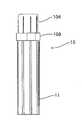
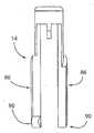
도 1 은 본 발명의 일 실시 형태에 따른 란셋의 측면도이다.
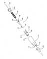
도 2 는 도 1 의 란셋의 분해도이다.
도 3 은 도 1 의 란셋의 분해 등각도이다.
도 4 는 작동전 란셋의 측단면도이다.
도 5 는 란셋을 찌르기 위치에 유지하는 구조체인 바늘 홀더를 갖는 작동된 (제 1 상태) 란셋의 측단면도이다.
도 6 은 바늘 홀더가 찌르기를 실행한 후에 하우징내에 후퇴되어 있는 작동된 란셋의 측단면도이다.
도 7 은 작동전 란셋의 개략적인 측면도이다.
도 8 은 바늘 홀더가 찌르기 위치에 있는 작동된 란셋의 개략적인 측면도이다.
도 9 는 바늘 홀더가 찌르기를 실행한 후에 하우징내에 후퇴되어 있는 작동된 란셋의 개략적인 측면도이다.
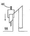
도 10a ? 10f 는 장치 하우징과 함께 바늘 홀더와 슬라이더의 인터페이스의 상세 내부 구성을 확대하여 나타낸 것으로, 란셋의 작동, 발사 및 회수의 일련의 아암을 나타내는데, 도 10a 는 장치를 환자의 조직에 눌러슬라이더를 작동시키기 전의 상태를 나타내고, 도 10b 는 슬라이더와 바늘 홀더가 짧은 레일에 대해 하우징 원위 단부쪽으로 또한 편향 수단(예컨대, 스프링)쪽으로 이동하는 것을 나타내며, 도 10c 는 경사 표면과 편향 수단 또는 스프링의 조합에 의해, 바늘 홀더의 접촉 표면과 짧은 레일의 끝벽이 정렬된 상태와, 란셋의 아아암이 이 포함된 복합 표면을 따라 아래로 슬라이딩하기 시작하는 것을 나타내며, 도 10d 는 아암이 슬라이딩하여 경사진 복합 표면에서 이탈하여 짧은 레일 옆에 있는 틈 안으로 아래로 이동하는 것을 나타내며, 도 10e 는 편향 수단에 의해 란셋에 부여된 운동으로 인해 그 란셋이 장치의 하우징에서 나가 환자의 피부나 조직을 찌르는 것을 나타내고, 도 10f 는 편향 수단이 그의 운동으로 야기된 과도 연장을 극복함에 따라 란셋이 장치 안으로 후퇴하여 란셋을 하우징 내부에 남겨 두는 것을 나타낸다.
도 11a ? 11b 는 2개의 상보적인 평면이 아닌, 슬라이더의 구동 표면과 바늘 홀더의 구동가능한 표면의 도 10의 상호 작용의 변형예를 나타내는 것으로, 도 11a 에는 슬라이더의 종동 표면(예컨대, 매끄럽고 둥근 표면)인 구동가능한 표면상에 슬라이딩하는 바늘 홀더의 편평한 구동가능한 표면이 나타나 있고, 도 11b 에는 반대로 되어 구동 표면이 편형한 구동 표면이고 구동가능한 표면은 종동 표면으로 되어 있는 것이 나타나 있다.
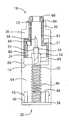
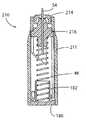
도 12 는 본 발명의 제 2 실시 형태의 분해도이다.
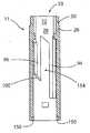
도 13a 는 제 2 실시 형태의 중공 하우징의 정면도이다.
도 13b 는 제 2 실시 형태의 중공 하우징의 수직 단면도이다.
도 13c 는 제 2 실시 형태의 중공 하우징의 저면도이다.
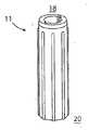
도 13d 는 제 2 실시 형태의 중공 하우징의 등각도이다.
도 14a 는 바늘 홀더의 정면도이다.
도 14b 는 바늘 홀더의 우측면도이다.
도 14c 는 바늘 홀더의 배면도로, 란셋은 숨겨져 점선으로 표시되어 있다.
도 14d 는 바늘 홀더의 평면도이다.
도 14e 는 바늘 홀더의 등각도이다.
도 15a 는 가이드체의 정면도이다.
도 15b 는 선 B - B 을 따라 취한 가이드체의 수직 단면도이다.
도 15c 는 가이드체의 저면도이다.
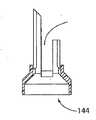
도 15d 는 가이드체의 등각도이다.
도 15e 는 가이드체의 저면 등각도이다.
도 15f 는 가이드체의 평면 등각도이다.
도 16a 는 슬라이더의 정면도이다.
도 16b 는 슬라이더의 측면도이다.
도 16c 는 슬라이더의 저면도이다.
도 16d 는 슬라이더의 등각도이다.
도 17 은 캡 덮개의 저면 등각도이다.
도 18a 는 캡의 수직 단면도이다.
도 18b 는 캡의 등각도이다.
도 19 는 제 2 실시 형태의 기부 캡의 평면 등각도이다.
도 20a 는 제 2 실시 형태의 스프링의 평면도이다.
도 20b 는 제 2 실시 형태의 스프링의 정면도이다.
도 21 은 본 발명의 다른 실시 형태의 분해 등각도로, 홀더의 제어를 도와 주는 탄성 밴드를 갖는 슬라이더를 나타낸다.
도 22 은 도 21 의 바늘 홀더의 측면도로, 캡이 바늘 가드에 부착되어 있다.
도 23 은 도 22 의 선 A - A 을 따라 취한 단면도로, 바늘 홀더의 제거가능한 가드는 캡내부에 숨어 있다.
도 24 는 초기 위치에 있는 바늘 홀더와 외측 위치에 있는 슬라이더를 나타내는 단면도이다.
도 25 는 중공 허우징의 근위 단부를 넘어 있는 전진 위치에 있는 바늘 홀더 및 밀린 위치에 있는 슬라이더를 나타내는 단면도이다.
도 26 는 중공 하우징내로 다시 후퇴된 후퇴 위치에 있는 바늘 홀더 및 밀린 위치에 있는 슬라이더를 나타내는 단면도이다.
도 27 은 바늘 홀더의 격리된 등각도로, 한쌍의 내측 윙 및 한쌍의 외측 윙그리고 캡 내부에서 캡과 결합하도록 되어 있는 바늘 가드에 있는 표면을 나타낸다.
도 28 은 중공 하우징의 단면도로, 이 중공 하우징의 내벽에 있는 적어도 하나의 멈춤 요소를 나타낸다.
도 29 는 탄성 밴드가 배치되는 홈을 갖는 슬라이더의 등각도이다.
도 30 은 홈을 갖는 슬라이더의 단면도이다.
도 31 은 탄성 밴드가 홈내에 있는 슬라이더의 등각도이다.
도 32 는 슬라이더에 있는 탄성 밴드와 결합하는 바늘 홀더의 내측 윙을 보여주는 등각도이다.1 is a side view of a lancet according to an embodiment of the present invention.
2 is an exploded view of the lancet of FIG. 1;
3 is an exploded isometric view of the lancet of FIG. 1.
4 is a side cross-sectional view of the lancet before operation.
5 is a cross-sectional side view of an activated (first state) lancet with a needle holder that is a structure that holds the lancet in the pricking position.
6 is a side cross-sectional view of the operated lancet being retracted in the housing after the needle holder has performed a prick.
7 is a schematic side view of a lancet before operation.
8 is a schematic side view of an activated lancet with the needle holder in the pricking position.
9 is a schematic side view of an activated lancet with the needle holder retracted in the housing after performing a prick.
10a? 10f shows an enlarged detailed internal configuration of the interface of the needle holder and slider with the device housing, showing a series of arms of actuation, firing and withdrawal of the lancet, FIG. 10a pressing the device against the tissue of the patient to activate the slider. 10b shows the slider and needle holder moving towards the distal end of the housing and towards the biasing means (eg spring) with respect to the short rail, and FIG. 10c shows the combination of the inclined surface and the biasing means or spring, The contact surface of the needle holder and the end wall of the short rail are aligned, and the arm of the lancet begins to slide down along the composite surface with the arm. To move down into the gap next to the short rail. FIG. 10E shows the number of deflections. The movement imparted to the lancet by means of the lancet exits the housing of the device and pierces the patient's skin or tissue, FIG. 10F shows that the lancet retracts into the device as the biasing means overcomes the excessive extension caused by its movement. Indicates leaving the lancet inside the housing.
11a? 11b represents a variant of the interaction of FIG. 10 between the drive surface of the slider and the driveable surface of the needle holder, rather than two complementary planes, in FIG. A flat driveable surface of the needle holder sliding on a possible surface is shown, and in FIG. 11B the reverse is shown that the drive surface is a flat drive surface and the driveable surface is a driven surface.
12 is an exploded view of a second embodiment of the present invention.
It is a front view of the hollow housing of 2nd Embodiment.
13B is a vertical sectional view of the hollow housing of the second embodiment.
13C is a bottom view of the hollow housing of the second embodiment.
13D is an isometric view of the hollow housing of the second embodiment.
14A is a front view of the needle holder.
14B is a right side view of the needle holder.
Fig. 14C is a rear view of the needle holder, in which the lancet is hidden and indicated by dashed lines.
14D is a top view of the needle holder.
14E is an isometric view of the needle holder.
15A is a front view of the guide body.
15B is a vertical sectional view of the guide body taken along the line B-B.
15C is a bottom view of the guide body.
15D is an isometric view of the guide body.
15E is a bottom isometric view of the guide body.
15F is a planar isometric view of the guide body.
16A is a front view of the slider.
16B is a side view of the slider.
16C is a bottom view of the slider.
16D is an isometric view of the slider.
17 is a bottom isometric view of the cap cover.
18A is a vertical sectional view of the cap.
18B is an isometric view of the cap.
19 is a planar isometric view of the base cap of the second embodiment.
20A is a plan view of the spring of the second embodiment.
20B is a front view of the spring of the second embodiment.
Figure 21 is an exploded isometric view of another embodiment of the present invention, showing a slider having an elastic band to assist control of the holder.
FIG. 22 is a side view of the needle holder of FIG. 21, with a cap attached to the needle guard.
FIG. 23 is a cross-sectional view taken along the line A-A of FIG. 22, wherein the removable guard of the needle holder is hidden inside the cap.
24 is a cross-sectional view showing the needle holder in the initial position and the slider in the outer position.
25 is a cross-sectional view showing the needle holder in the forward position and the slider in the pushed position beyond the proximal end of the hollow housing.
FIG. 26 is a cross sectional view of the needle holder in the retracted position and the slider in the retracted position, retracted back into the hollow housing; FIG.
FIG. 27 is an isolated isometric view of the needle holder showing a pair of inner wings and a pair of outer wings and a surface on the needle guard adapted to engage the cap inside the cap.
28 is a cross sectional view of the hollow housing, showing at least one stop element on the inner wall of the hollow housing;
29 is an isometric view of a slider having a groove in which an elastic band is disposed.
30 is a cross-sectional view of the slider with grooves.
31 is an isometric view of the slider with the elastic band in the groove.
32 is an isometric view showing the inner wing of the needle holder engaging the elastic band in the slider.
첨부된 도면은 반드시 축척에 맞게 그려진 것은 아니며, 본 발명의 기본 원리를 예시하는 다양한 바람직한 요소를 다소 단순화시켜 나타낸 것임을 이해하여야 한다. 예컨대 란셋의 특정 치수를 포함하여 본원에서 개시된 란셋의 특정 설계 요소는 부분적으로는 특정의 의도된 용도 및 사용 환경에 의해 결정될 것이다. 도시도니 실시 형태의 어떤 요소는 명확한 이해를 돕기 위해 다른 것에 비해 확대 또는 왜곡되었다. 특히, 얇은 요소는 예컨대 명확한 도시를 위해 두껍께 되어 나타날 수도 있다. 다른 언급이 없으면, 모든 방향 및 위치는 도면에 도시되어 있는 방향을 말하는 것이다.It is to be understood that the accompanying drawings are not necessarily drawn to scale, but rather rather simplified in various preferred elements illustrating the basic principles of the invention. The particular design element of the lancet disclosed herein, including, for example, the specific dimensions of the lancet, will be determined in part by the particular intended use and environment of use. Some elements of the illustrated embodiment have been enlarged or distorted relative to others to aid clear understanding. In particular, thin elements may appear thick, for example for clarity. Unless otherwise stated, all directions and positions refer to the directions shown in the figures.
당업자, 즉 본 기술 분야에의 지식이나 경험을 갖고 있는 사람들에게는, 본원에 개시된 란셋 장치에 대해 많은 사용 및 설계 변경이 가능함이 명백할 것이다. 다양한 대안적인 또한 바람직한 요소 및 실시 형태에 대한 이하의 상세한 설명은 혈액 샘플 시험에 사용되는데 적절한 란셋 장치와 관련한 본 발명의 일반적인 원리를 예시할 것이다. 다른 용도에 적합한 다른 실시 형태도 본 개시의 이익을 얻는 당업자에게 명백할 것이다.It will be apparent to those skilled in the art, that is, those with knowledge or experience in the art, that many uses and design changes are possible with the lancet device disclosed herein. The following detailed description of various alternative and also preferred elements and embodiments will illustrate the general principles of the present invention in connection with a lancet device suitable for use in blood sample testing. Other embodiments suitable for other uses will be apparent to those skilled in the art having the benefit of this disclosure.
도면을 참고하면, 도 1 은 란셋 장치(10)의 측면도로, 이 장치는 중공 하우징(11), 덮개(104) 및 링(108)을 갖는다. 도 2 는 제 1 실시 형태의 란셋 장치(10)의 분해 등각도이다. 란셋 장치(10)는 일반적으로 중공 하우징(11), 편향(biasing) 조립체(12) 및 움직일 수 있게 중공 하우징(11)과 결합하는 란셋 부 조립체(13)를 포함한다. 란셋 부조립체(13)는 슬라이더(14) 및 바늘 홀더(16)를 포함한다. 중공 하우징(11)은 근위 단부(18)(찌를 환자의 피부나 조직(116)에 위치되는 단부) 및 원위 단부(20)(근위 단부(18)의 반대쪽 단부임)를 갖는다. 중공 하우징의 근위 단부(18)는 근위 단부 개구(127)를 갖는다.Referring to the drawings, FIG. 1 is a side view of a
슬라이더(14)는 부분적으로 중공 하우징(11)의 내부에 배치되며, 환자 접촉부 또는 받침면이 근위 단부 개구(127)를 통해 근위 단부(18)에서 중공 하우징(11)으로부터 부분적으로 연장되어 있다.The
란셋 부조립체(13)는 중공 하우징(11)내에서 축방향 또는 길이 방향으로 움직일 수 있다. 바늘 홀더(16)가 작동적으로 슬라이더(14)와 관련되어 있다. 이러한 축방향 운동은, 종공 하우징(11)의 일반적인 길이에 대한 슬라이딩(14) 또는 홀더(16) 또는 이들 두 요소의 축방향 운동 및/또는 회전 운동을 포함하여, 그 슬라이더와 바늘 홀더의 서로에 대한 운동을 포함한다.The
중공 하우징(11)은 일체적으로 형성될 수 있다. 대안적으로, 중공 하우징(11)은 길이방향으로 또는 다르게 분할되어 있는 개별적인 부분들로 형성될 수도 있다. 각각의 부분은 적절한 접착제 또는 상기 부분들 사이의 기계적 부착을 제공하는 적절한 상호결합 구조(마찰 끼워맞춤이나 스냅식 끼워맞춤 구조와 같은)를 통해 서로에 고정될 수 있다.The
중공 하우징(11)은 기다란 몸체(21)를 가지며, 이들 둘은 공통의 중심 종축선을 갖는다. 몸체(21)는 어떤 적절한 형태로도 형성될 수 있다. 바람직하게는, 몸체(21)는 원통형이다. 몸체(21)의 내부는 일반적으로 중공이다. 몸체(21)는 환형 단면의 내벽(22)을 갖는다. 이 내벽(22)은 근위 단부(18)에서부터 원위 단부(20)까지 이르는 일정한 원통형 내부 공동부(24)를 형성한다. 슬라이더(14)와 바늘 홀더(16)는 내부 공동부(24) 안에 들어 있게 된다. 몸체(21)는 중공 하우징(11)의 원위 단부(20)에서부터 근위 단부(18)까지 길이방향으로 뻗어 있는 복수의 외부 리브(25)를 가질 수 있다. 이 리브(25)는 환자가 란셋 장치(10)를 잡는데 도움을 준다. 란셋 장치(10)의 파지를 개선하는 표면을 제공하기 위해 다른 구성도 사용될 수 있다. 예컨대, 몸체(22)의 외부 표면은 환자 손가락을 수용하도록 형성될 수 있으며(예컨대, 손가락 파지 오목부가 형성될 수 있음) 또는 결이 만들어질 수 있거나 아니면 다르게 될 수도 있다.The
바람직한 실시 형태에서, 하우징(11)은 몸체(21)로부터 이 몸체(21)의 중심 종축선의 안쪽으로 연장되어 있는 테두리부(26)를 포함하며, 이 테두리부(26)의 외측 가장자리는 몸체(21)에 결합되어 있다. 바람직하게 테두리부(26)는 몸체(21)에 수직하다. 테두리부(26)는 중공 하우징(11)의 근위 단부(18)에서 내부 공동부(24)를 부분적으로 시일링하게 된다. 테두리부(26)의 내측 가장자리는 환형 구멍(28)을 둘러싼다. 이 구멍(28)은 내부 공동부(24)와 연통되어 있다. 중공 하우징(11)은 칼라(30)를 포함하는데, 이 칼라는 몸체(21)의 중심 종축선에 평행하게 테두리부(26)로부터 돌출해 있고 테두리부(26)의 내측 가장자리 주위에 연장되어 있어 연결 통로(32)를 둘러싼다. 연결 통로(32)의 일 단부는 구멍(28)이다. 연결 통로(32)와 구멍(28)은 같은 직경을 갖는다. 개구(28)의 반대편에는 연결 통로(32)의 개구(33)가 있다. 연결 통로(32)는 구멍(28)을 통해 내부 공동부(24)와 연통한다. In a preferred embodiment, the
테두리부(26)와 칼라(30)는 몸체(21)와 일체적으로 형성될 수 있다. 대안적으로, 테두리부(26) 및 칼라(30)는 몸체(21)와는 별개인 단일체로 형성되어 그 몸체에 부착될 수 있다. 이러한 구성에서 칼라(30)와 함께 테두리부(26)는 적절한 접착제나 근위 단부(18)에서 테두리부(26)와 몸체(21) 사이에 기계적 부착을 제공하는 적절한 상호결합 구조(마찰 끼워맞춤이나 스냅식 끼워맞춤 구조, 나사 구조와 같은)를 통해 몸체(21)의 근위 단부(18)에 부착된다. 슬라이더(14)는 중공 하우징(11)으로부터 구멍(28)과 연결 통로(32)를 통해 개구(33) 밖으로 부분적으로 나가 있다.The
중공 하우징(11)의 원위 단부(20)에는 내부 공동부(24)에 이르는 후방 개구(34)가 있다. 기부(36)가 후방 개구(34)에서 몸체(21)와 결합하여 내부 공동부(24)를 폐쇄하게 되며, 따라서 몸체(22)의 중심 종축선은 기부(36)의 중심점과 교차하게 된다. 중공 하우징(11)이 길이방향으로 두 부분으로 나누어진 구조가 선택적으로 채용되는 경우에는 상기 기부(36)는 필요 없다.At the
기부(36)는 몸체(21)와는 별개인 요소로 형성될 수 있다. 기부(36)는 적절한 접착제 또는 기부와 몸체 사이에 기계적인 부착을 제공해 주는 상호결합 구조(마찰 끼워맞춤이나 스냅식 끼워맞춤 구조, 나사 결합 등과 같은)를 통해 원위 단부(20)에서 몸체(21)에 부착될 수 있다. 기부(36)는 플레이트(38)를 포함한다. 바람직하게 이 플레이트(38)는 몸체(21)에 대응하는 경계부를 갖는다. 예컨대, 기부(36)와 몸체(21) 사이의 상호결합 구조로 스냅식 끼워맞춤 방식이 사용되는 경우, 클래스프(40)가 플레이트(38)의 일측면에 설치된다. 이 클래스프(40)는 몸체(21)의 내벽(22)의 대응 홈에 결합되는 상대 표면(42)을 갖는다. 클래스프(40)는 기부(36)의 중심점의 양측에서 플레이트(38)의 경계부에 인접하여 배치된다. 몸체(21)의 내벽(22)에는 홈으로 이르는 가이드가 선택적으로 제공된다. 기부(36)가 몸체(21)에 결합하면, 클래스프(40)는 상대 표면(42)으로 내벽(22)을 따라 상기 홈에 스냅식 끼워맞춤된다. 클래스프(40)는 바람직하게는 탄력적인 재료로 만들어진다. 기부(36)와 몸체(21) 사이의 상호결합 구조의 상기 요소들의 배치는 단지 예시적인 것이고, 몸체(21)에 기부(36)를 부착하기 위해 다른 상호결합 구조도 사용할 수 있다.
편향 조립체(12)는 조립되면 기부(36)에 접하게 된다. 란셋 부조립체(13)는 편향 조립체(12)에 결합하며, 이 편향 조립체는 중공 하우징(11) 안에서 란셋 부조립체(13)를 움직이게 하고 또한 란셋 조립체의 바늘 홀더(16)와 슬라이더(14) 사이의 작동적인 상호작용을 위한 것이다. 편향 조립체(12)는 바늘 홀더(16)가 근위 단부쪽으로 구동되도록 그 바늘 홀더(16)에 편향력을 가하도록 되어 있다. 이 편향 조립체(12)는 기부(36)의 플레이트(38)에 결합되는 별도의 요소이거나 또는 플레이트(38)와 일체적으로 형성될 수도 있다.The
편향 조립체(12)는 플레이트(38)에 결합되거나 이 플레이트(38)와 일체적을 형성되는 예컨대 탄성적인 부재(이에 한정되지 않음)와 같은 편향 수단(46)일 수 있다. 바람직하게는, 편향 수단(46)은 금속 또는 플라스틱 스프링이다. 대안적으로, 편향 조립체(12)는 편향 수단(46)을 플레이트(38)에 연결하기 위해 기부(36)의 플레이트(38)에 연결되는 연결 부재(48)를 추가로 포함할 수 있다. 이 연결 부재(48)는 플레이트(38)의 중심부에 배치되며, 따라서 기부(36)가 후방 개구(38)에서 몸체(21)에 결합하여 내부 공동부(24)를 폐쇄하면, 몸체(21)의 중심 종축선이 상기 연결 부재(48)와 교차하게 된다. 연결 부재(48)는 란셋 부조립체(13)와의 결합에 적절한 배향으로 편향 수단(46)을 지지하게 된다. 바람직하게는, 연결 부재(48)는 편향 수단(46)의 일 단부를 수용하기 위한 정렬 보스(boss)이다.The
란셋 부조립체(13)는 편향 수단(46)의 반대쪽 단부와 결합하기 위한 결합 부재(50)를 포함할 수 있다. 바람직하게는, 결합 부재(50)는 편향 수단(46)의 반대쪽 단부를 수용하기 위한 정렬 보스이다. 바람직한 실시 형태에서, 편향 수단(46)은 기부(36)에 연결된 연결 부재(48)와 란셋 서브어세블리(13)에 연결된 결합 부재(50) 사이에 연결된다. 란셋 장치(10)의 작동의 초기 단계 중에, 란셋 부조립체(13)는 편향 조립체(12)쪽으로 축방향으로 중공 하우징 안으로 밀리게 되며, 그리 하여 그 편향 조립체(12)가 예컨대 압축으로 에너지를 저장하게 된다. 압축력을 해제하면, 편향 조립체(12)에 저장되어 있던 퍼텐셜 에너지가 란셋 장치(12)의 바늘 홀더(16)에 힘을 가하여, 그 바늘 홀더(16)가 중공 하우징(11)의 중심 종축선(118)을 따라 근위 단부(18)쪽으로 편향되어 연결 통로(32)를 통해 찌르기 지점에 이르게 된다. 바늘 홀더(16)는 일시적으로 찌르기 지점에 도달한다. 편향 조립체(12)와 란셋 장치의 운동량 때문에, 편향 조립체(12)의 과도 연장이 일어나게 된다. 그런 다음 편향 조립체(12)는 그의 과도 연장 상태에서 안쪽으로 수축되며 바늘 홀더(16)는 중공 하우징(11) 안으로 후퇴하게 된다. 이 바늘 홀더(16)의 후퇴로 인해, 혈액을 통한 질병이 란셋의 사용 후에 우발적인 상처를 통해 전달될 가능이 없어진다.The
란셋 부조립체(13)는 슬라이더(14) 및 바늘 홀더(16)를 포함하는데, 이들 슬라이더와 바늘 홀더는 중공 하우징(11)의 중심 종축선(118)을 따라 이동한 후에 환자의 피부나 조직(116)을 찌르도록 바늘 홀더(16)를 가 발사하도록 구성되어 있다.The
바늘 홀더(16)는 길이방향 회전 축선을 가지며 스템(52)을 포함하는데, 이 스템은 로드로 형성될 수 있다. 스템(52)의 일 단부는 결합 부재(50)에 연결될 수 있고 이들 둘은 단일체로 형성될 수도 있다. 스템(52)의 반대쪽 단부는 랜스(54)를 수용하도록 되어 있다. 랜스(54)를 수용하는 상기 단부로부터 보어(56)가 부분적으로 스템(52)을 통해 형성되어 있다. 이 보어(56)는 중공 하우징의 종축선(118)과 동축이다. 보어(56)는 란셋 장치(10)에 사용될 랜스(54)에 따라 형성될 수 있다.The
바늘 홀더(16) 또는 그의 일 부분을 랜스(54)에 만들어 이 랜스(54)는 그 바늘 홀더의 스템(52) 내부에 잡혀 있을 수 있다. 대안적으로, 랜스는 억지 끼워맞춤으로 스템에 배치될 수 있으며 또는 상보적인 구조 결합을 가질 수 있다.The
보어(56)는 랜스(54)를 바늘 홀더(16)에 안정적으로 유지시킨다. 랜스(54)가 보어(56) 안으로 삽입되면, 랜스(54)는 바늘 홀더(16)의 회전 축선을 따라 정렬된다. 바람직하게는, 스템(52)으로부터 슬리브(53)가 바늘 홀더(16)의 회전 축선과 평행하게 연장되어 있다. 슬리브(53)는 스템(52)의 내주에서 보어(56)의 개구를 따라 있다.The
란셋(54)은 찌르기 단부(58)를 갖는 란셋이나 블레이드일 수 있다. 찌르기 단부(58)는 찌르기 지점에서 환자의 피부를 찌르게 되며, 뾰족한 단부 또는 블이드날을 규정할 수 있으며, 또한 바람직한 정렬 방향을 포함할 수 있다.The
바늘 홀더(16)는 중공 하우징(11) 안에서 길이방향 운동 및 회전 운동을 하도록 되어 있고, 찌르기 단부(58)가 중공 하우징(11)의 근위 단부(18) 내부에 있는 초기 위치로부터, 편향 조립체(12)가 압축되어 바늘 홀더가 슬라이더(14)에서 분리되는 분리 위치, 끼르기 단부(58)가 편향되어 연결 통로(32)를 통해 개구(33)를 넘어 전진하는(환자의 피부나 조직을 찌르기 위해) 찌르기 위치 및 마지막으로 찌르기 단부(58)가 중공 하우징(11) 안으로 후퇴되는 찌르기 후 위치까지 움직일 수 있다.The
바늘 홀더(16)는 스템(52)에 부착되어 있는 아암(60)을 포함한다. 각각의 아암(60)은 바늘 홀더(16)의 종축선(118)으로부터 멀어지게 반경항향으로 또한 바람직하게는 그 종축선에 수직하게 연장되어 있다. 바람직하게는, 스템(52)과 아암(60)은 일체적으로 형성된다. 각각의 아암(60)은 스템(52) 주위에 일정한 간격으로 서로 떨어져 있어 틈(62)을 형성한다. 적어도 하나의 틈(62)이 제공된다면, 아암(60)의 수는 본 발명의 요지에서 벗어나지 않고 변할 수 있다. 예컨대, 일부 실시 형태에서는 단지 하나의 아암(60)만 존재할 수 있다.The
조립된 란셋 장치(10)에서, 아암(60)은 스템(22)에 대한 부착 지점에서부터 내벽(22)까지 이르며, 바늘 홀더(16)가 중공 하우징(11) 내부에서 길이방향 운동과 회전 운동을 하는 중에 내벽(22)에 슬라이딩하면서 접촉하게 된다. 바람직하게는, 내벽(22)과 접촉하는 아암(60)의 표면은 그 내벽(22)의 곡률에 대응하는 곡률로 형성된다. 아암(60)들의 길이는 바람직하게는 같고, 바늘 홀더(16)가 중공 하우징(11) 안에 배치되면 스템(52)이 내벽(22) 사이에서 중공 하우징(11) 내부에서 중앙에 위치되며 바늘 홀더(16)의 회전 축선이 중공 하우징(11)의 중심 종축선과 정렬하도록 되어 있다.In the assembled
각각의 아암(60)은 구동가능한 표면을 포함한다. 일 실시 형태에서, 구동가능한 표면은 결합 표면(64)인데, 이 표면을 통해 바늘 홀더(16)가 슬라이더(14)와 상호 작용하게 된다. 각각의 결합 표면(64)은 스템(52)에 부착되는 내측 가장자리 및 내부벽(22)과 가동 접촉하는 외측 가장자리를 갖는다. 각각의 결합 표면(64)은 일반적으로 중공 하우징(11)의 근위 단부(18) 쪽으로 향한다. 결합 표면(64)은 종축선으로부터의 반경방향 라인상에 있는데, 다시 말해 종축선(118)에 수직이다. 결합 표면은 또한 이 반경방향 라인 주위로 회전되어 있는데, 따라서 이 결합 표면의 법선은 종축선에 대해 각을 이루면서 기울어져 있다.Each
결합 표면(64)은 10°? 80°의 경사각을 가지며, 바람직한 실시 형태에서는 45°의 경사각을 갖는다. 이 경사각은 후술하는 바와 같이 변할 수 있다. 각 아암(60)의 결합 표면(64)은 동일한 방향으로 경사져 있고 동일한 경사각을 갖는다. 아암(60)은 슬라이더(14)와 함께 움직이는 동안에 그 슬라이더와의 결합을 위한 플랫폼을 제공하며 그래서 바늘 홀더에 가해지는 힘에 저항하도록 형성되어 있다.The
슬라이더(14)는 종축선을 가지며, 란셋(54)으로 찔러질 환자 피부와 접촉하는 찌르기용 표면(68)을 규정하는 디스크(66)를 포함한다. 이 디스크(66)는 찌르기용 표면(68)의 반대편에 있는 받침면(70)을 포함한다. 디스크(66)의 중심점은 슬라이더(14)의 종축선과 정렬된다. 디스크(66)는 중공 하우징(11)의 연결 통로(32)를 통해 움직일 수 있다. 디스크(66)는 경사가공된(bevelled) 외측 가장자리를 가질 수 있는데, 이러한 가장자리는 디스크(66)의 외측 가장자리와 연결 통로(32)를 둘러싸는 칼라(30)의 벽 사이의 마찰 접촉을 줄여준다. 디스크(66)의 중심족에는 찌르기 구멍(72)을 규정하는 내측 가장자리가 있다. 구멍(72)은 슬라이더(14)의 종축선의 방향으로 디스크(66)를 통해 연장되어 있다. 란셋 장치(10)가 환자의 피부에 접해 배치되면, 디스크(66)의 찌르기 표면(68)이 환자의 피부와 접촉하게 된다. 란셋 장치(10)가 작동되면, 환자 피부의 일 부분이 찌르기 구멍(72) 안으로 부풀게 된다. 란셋 장치(10)가 작동된 후에는, 랜스(54)의 찌르기 단부(58)가 찌르기 구멍(72)을 통해 튀어 나가 환자의 피부를 찌르게 된다.The
이제 설명하는 바와 같이 슬라이더(14)의 길이방향 운동이 제한될 수 있고, 회전 운동은 바람직하게 억제된다. 연결 통로(32)는 서로 마주하는 측에서 홈(74)을 포함할 수 있다. 각각의 홈(74)은 중공 하우징(11)의 중심 종축선에 평행하고 또한 연결 통로(32)의 개구(33)로부터 구멍(28) 쪽으로 연장되어 있다. 각각의 홈(74)은 립(76)에 의해 구멍(28)으로부터 분리되어 있다. 립(76)은 연결 통로(32)의 개구(33)에도 배치될 수 있다. 클립 아암(78)이 받침면(70)에서 디스크(66)에 부착될 수 있다. 슬라이더(14)가 중공 하우징(11) 안에 배치되면, 조립된 장치에서 디스크(66)는 슬라이딩가능하게 연결 통로(32)에 둘러싸이고 이에 대응하여 클립 아암(78)은 각각의 홈(74) 안에 슬라이딩가능하게 위치된다. 디스크(66) 및 그래서 슬라이더(14)의 길이방향 운동의 범위는 홈(78)을 따르는 클립 아암(78)의 운동 및 립(76)에 의해 제한된다. 클립 아암(78)과 홈(74)의 벽의 상호 결합에 의해 디스크(66)의 어떤 회전 운동도 억제된다.As will now be explained, the longitudinal movement of the
반경방향 프롭(prop)(8))과 같은 구동부가 받침면(70)에서 연장되어 있다. 바람직하게는 디스크(66)와 프롭(80)은 일체적으로 형성된다. 각각의 프롭(80)은 슬라이더(14)의 종축선에 평행하게 연장되어 있는 다리부(82)를 포함한다. 각 다리부(82)의 끝에는 반경방향 외측의 플랜지(84)가 슬라이더(14)의 종축선에서 멀어지는 방향으로 다리부(82)로부터 일반적으로 수직하게 연장되어 있다. 플랜지(84)의 길이는 내벽(22)과 구멍(28)의 가장자리 사이의 테두리부(26)의 폭과 같을 수 있다. 발부(86)가 일반적으로 다리부(82)에 평행하게 각 플랜지(84)로부터 연장되어 있다. 슬라이더(14)가 중공 하우징(11) 안에서 길이방향 운동을 하는 중에 발부(86)의 외측 표면은 내벽(22)과 접촉하여 그를 따라 슬라이딩하도록 되어 있다. 바람직하게는, 내벽(22)과 접촉하는 각 발부(86)의 외측 표면은 내벽(22)의 곡률에 대응하는 곡률로 형성되어 있다. 그러므로 구동부는 프롭(80), 다리부(82), 플랜지(84) 및 발부(86)로 이루어진다.A drive, such as a radial prop 8, extends from the bearing
각 발부(86)의 끝에는 접촉 표면(90)으로서 경사 구동 표면이 있다. 바람직한 실시 형태에서, 접촉 표면(90)의 경사는 아암(60)의 결합 표면(64)의 경사에 대응하고 또한 그에 상보적이다.At the end of each
본 발명의 다른 형태에서, 상기 구동 표면 및 구동가능한 표면은 서로에 대해 슬라이딩할 수 있기만 하면 된다. 이를 달성하기 위한 많은 방법들이 당업자에명백할 것이다. 이러한 일 방법이 도 11 에 나타나 있다. 도 11a 는 편평한 구동가능한 표면(124)으로서 경사진 구동가능한 표면을 갖는 아암(60)을 보여주는데, 이 구동가능한 표면은 종동 표면(123)(이 경우는 구동부의 발부(86)의 연장부)인 구동 표면과 결합하게 된다. 끝벽(100)의 자유 단부(120)가 치워지며, 랜스(54)의 작동하에서 구동부가 올라가면, 아암(60)의 편평한 구동가능한 표면(124)은 종동 표면(123)에서 슬라이딩하거나 그 위에서 따르게 된다.In another form of the invention, the drive surface and the driveable surface only need to be able to slide relative to each other. Many ways to accomplish this will be apparent to those skilled in the art. One such method is shown in FIG. 11. FIG. 11A shows an
등가적인 반대 구조가 도 11b 에 나타나 있는데, 여기서는 구동 표면이 발부(86)의 일 부분인 편평한 구동 표면(122)으로 되어 있으며, 이 표면에서는 종동 표면(123)인 구동가능한 표면이 슬라이딩할 수 있다.An equivalent counter structure is shown in FIG. 11B, where the drive surface is a
다른 실시 형태에서, 구동가능한 표면이 구동 표면 및 끝벽 또는 자유 단부위를 슬라이딩하거나 이를 지날 수 있다면, 구동 표면 및/또는 구동가능한 표면 및/또는 끝벽은 만곡되거나 또는 다르게 형성될 수 있다.In other embodiments, the drive surface and / or driveable surface and / or end wall may be curved or otherwise formed if the driveable surface can slide over or pass over the drive surface and end wall or free end.
아암(60)의 외측 가장자리와 발부(86)의 외측 표면은 고른 표면을 형성한다. 바람직하게는, 플랜지(84)는 접촉면(90)에 평행하게 그래서 동일한 경사각을 갖도록 형성된다.The outer edge of the
프롭(80)은 디스크(66)의 외주 주위에 일정한 간격으로 서로 떨어져 있어 슬롯(88)을 형성한다. 바늘 홀더(16)의 아암(60)이 슬라이더(14)의 슬롯(88) 안으로 움직일 수 있고 또한 슬라이더(14)의 프롭(80)이 바늘 홀더(16)의 틈(62) 안으로 움직일 수 있어 슬라이더(14)와 바늘 홀더(16)는 분리 후에 서로를 향해 움직일 수 있다. 프롭(80)의 수는 아암(60)의 수와 같아야 한다.The
란셋 장치(10)가 조립되면, 중공 하우징(11)의 중심 종축선, 슬라이더(14)의 축선 및 바늘 홀더(16)의 회전 축선은 일치하게 된다. 란셋 장치(10)의 작동 전에, 결합 표면(64)과 접촉 표면(90)이 마찰 결합한 상태에서 슬라이더(14)는 중공 하우징(11) 안에 배치된다. 결합 표면(64)과 접촉 표면(90)의 마찰 결합이 서로 반대로 작용하는 힘들(한 힘은 슬라이더(14)에 작용하고 다른 힘은 바늘 홀더(16)에 작용함)에 의해 극복될 때까지 그 마찰 결합을 유지하기 위해 경사도를 적절히 변경할 수 있다.When the
찌르기 표면(68)이 환자의 피부나 조직(116)에 접촉하면, 슬라이더(14)는 축선방향으로 원위 단부(20) 쪽으로 중공 하우징(11) 안으로 밀리게 된다. 슬라이더(14)와 바늘 홀더(16)가 접하여 결합해 있을 때 이들 둘은 편향 조립체(12) 쪽으로 단일체로 움직이게 된다. 이 결과 편향 조립체(12)가 압축되어 그 편향 조립체(12)의 퍼텐셜 에너지가 증가하게 된다. 편향 조립체(12)가 압축됨에 따라, 편향 조립체(12)는 란셋 부조립체(13)에 힘을 가하게 된다. 따라서 서로 반대로 작용하는 힘들이 중공 하우징(11)의 종축선을 따라 란셋 부조립체(13)에 작용하게 된다.When the
도 10a ? 10f 에서 보는 바와 같이, 바늘 홀더가 원위 단부(20) 쪽으로 변위하는 중에, 구동 표면이나 구동가능한 표면 중의 적어도 하나는 경사져 있어 바늘 홀더(16)의 스템(52) 또는 그의 표면을 가이드 레일(96) 또는 그의 가이드 표면(125) 쪽으로 편향시키게 된다. 가이드 레일(96) 또는 그의 가이드 표면(125)의 회전 구속이 없기 때문에, 바늘 홀더의 구동가능한 표면은 원위 단부(20) 쪽으로 충분히 변위되면 짧은 가이드 레일(94)의 자유 단부(120) 위로 가게 된다. 그런 다음에, 바늘 홀더는 종축선(118) 주위로 회전할 수 있으며, 그리고 자유 단부(120)를 지날 수 있다. 그런 다음, 바늘 홀더는 편향 수단에 의해 충분한 운동량을 갖고 근위 단부(18) 쪽으로 보내져, 찌르기 단부(58)가 충분한 힘으로 근위 단부 개구(72)를 통과해 전진하여 그와 접촉하는 조직(116)을 찌르게 된다. 그런 다음, 찌르기 단부(58)가 근위 단부 개구(72)를 넘어 있지 않도록 하기에 충분히 바늘 홀더(52)가 편향 수단에 의해 후퇴된다.10a? As seen at 10f, while the needle holder is displaced towards the
처음에, 결합 표면(64)과 접촉 표면(90) 사이의 마찰력은 편향 조립체(12)에서 주어지는 힘과 환자로부터의 미는 힘의 합력 보다 커서, 바늘 홀더(16)와 슬라이더(14)는 일체로 움직일 수 있다. 란셋 장치(10)가 환자에 가압됨에 따라, 란셋 부조립체(13)는 중공 하우징(11) 안으로 더 밀리게 되고, 그리 하여 편향 조립체(12)의 퍼텐셜 에너지가 증가하고 또한 란셋 부조립체(13)에 작용하는 합력이 증가하게 된다. 이 합력은 결합 표면(64)과 접촉 표면(90) 사이의 마찰력이 극복되어 결합 표면(64)과 접촉 표면(90)이 축선에서 벗어나 정렬됨으로 인해 서로에 대해 슬라이딩할 때가지 증가된다. 서로에 대한 표면의 슬라이딩은, 바늘 홀더(16)가 그의 회전 축선 주위로 회전할 수 있기 때문에 이루어진다. 하지만, 여기서 설명하는 바와 같이, 슬라이더(14)는 어떠한 회전 운동도 할 수 없다. 상기 합력이 계속 증가하면, 결합 표면(64)과 접촉 표면(90)이 분리될 때까지 이들 두 표면 사이의 슬라이딩이 더 일어나게 된다.Initially, the frictional force between the
조립된 란셋 장치(10)에서, 슬라이더(14)의 접촉 표면(90)은 원위 단부(20) 에 더 가까운 가장자리 및 원위 단부(20)에 더 가까운 가장자리를 갖는다. 분리는 근위 단부(18)에 더 가까운 가장자리에서 일어난다. 분리가 일어나는 근위 단부(18)에 더 가까운 가장자리에 인접한 발부(86)의 각 측을 이하 "분리측"(92)이라고 한다.In the assembled
일단 분리가 일어나면, 편향 조립체(12)에 있는 퍼텐셜 에너지가 방출되어 바늘 홀더(16)가 축방향으로 중공 하우징(11)의 중심 종축선을 따라 근위 단부(18) 쪽으로 보내지게 된다. 바늘 홀더(16)는 디스크(66) 쪽으로 이동하고 랜스(54)의 찌르기 단부(58)는 찌르기 구멍(72)을 통해 슬라이딩하여 환자 피부의 찌르기 지점에 도달하여 피부를 찌르게 된다. 스템(52)이 디스크(66)의 받침면(70)에 접촉함으로써 바늘 홀더(16)는 더 이상 이동하지 못하게 된다. 그런 다음, 편향 조립체(12)는 바늘 홀더(16)를 중공 하우징(11) 안으로 다시 끌어 당겨 찌르기 단부(58)를 중공 하우징(11) 안에 보호해 둔다.Once separation occurs, the potential energy in the
일 실시 형태에서, 내벽(22)은 한 세트의 가이드 레일(94, 96)을 가질 수 있는데, 이들 레일은 슬라이더(14)의 발부(86)와 결합하여 바늘 홀더(16)의 아암(60)을 안내하기 위한 것이다. 긴 레일(94)은 짧은 레일(96)과 번갈아 있다. 긴 레일(94)의 수와 짧은 레일(96)의 수는 프롭(80)과 아암(60)의 수에 대응한다. 가이드 레일은 하우징(11)의 중심 종축선에 평행하게 테두리부(26)로부터 원위 단부(20) 쪽으로 연장되어 있다. 긴 레일(94)과 짧은 레일(96) 사이에는 채널 또는통로(98)가 있다. 가이드 레일(94, 96)의 기다란 측은 구동부(즉, 프롭(80), 다리부(82), 플랜지(84) 및 발부(86))의 기다란 부분을 안내하는 가이드 표면(125)을 규정한다. 이들 가이드 표면은 또한 아암(60)이 짧은 레일(96)의 끝벽(100)의 자유 단부(120)에 도달할 때까지 그 아암을 안내한다.In one embodiment, the
조립된 란셋 장치(10)에서, 슬라이더(14)의 발부(86)는 통로(98)에 유지되고 가이드 표면(125)에 의해 안내되어 중공 하우징(11)내의 슬라이더(14)의 회전 운동을 더 억제하지만 그 슬라이더의 축방향 운동은 허용다. 통로(98)의 수는 발부(86)의 수와 아암(60)의 수를 합한 것과 같다. 그래서, 작동전 란셋 장치(10)에서는, 아암(60)이 발부(86)와 결합해 있을 때 점유되지 않고 남아 있는 통로(98)가 있다. 바람직하게는, 긴 레일(94)은 바늘 홀더(16)와 슬라이더(14) 사이의 분리가 일어나는 지점(중공 하우징(11)을 따르는 지점임)을 넘어 연장되어 있다. 바람직하게는, 슬라이더(14)가 작동전 위치에 있을 때, 짧은 레일(96)은 중공 하우징(11)에 있는 접촉 표면(90)의 위치까지 연장되어 있다.In the assembled
도 10a 에서 보는 바와 같이, 짧은 레일(96)은 접촉 표면(90)과 동일한 방향으로 경사져 있는 끝벽(100)을 갖는데, 이 끝벽은 결합 표면(64)에 대응한다. 짧은 레일(96)은 발부(86)의 분리측(92)에 배치된다. 란셋 장치(10)가 작동한 후에, 슬라이더(14)와 바늘 홀더(16) 사이의 분리가 일어날 때, 접촉 표면(90)은 끝벽(100)과 정렬되거나(도 10b) 또는 그에서 약간 튀어 나오게 된다. 따라서, 편향 조립체(12)와 경사진 표면의 조합에 의해 아암(60)은 분리측(92)에서 발부(86) 위를 슬라이딩하고 또한 끝벽(100)을 따라 슬라이딩하게 된다. 끝벽(100)이 대응적으로 경사져 있으므로, 도 10c ? 10d 에서 보는 바와 같이 아암(60)의 결합 표면(64)은 그 끝벽(100)을 따라 슬라이딩하여 비점유 통로(98) 안으로 들어간다. 거기서 부터 랜스가 자유롭게 작동할 수 있어(자유롭게 발사 가능함), 중공 하우징 밖으로 나가 환자의 피부(116)를 찌르게 된다 (도 10e 참조).As shown in FIG. 10A, the
통로(98)는 테두리부(26)로부터 어느 정도까지 통로(98) 안으로 연장되어 있는 리지(102)를 포함할 수 있다. 이 리지(102)는 슬라이더(14)의 플랜지(84)와 바늘 홀더(16)의 아암(60)을 위한 받침면을 제공한다. 근위 단부(18) 쪽으로 향하는 슬라이더(14)의 길이방향 운동은 플랜지(84)와 리지(102)의 접촉으로 억제된다. 작동 후에, 근위 단부(18) 쪽으로 향하는 바늘 홀더(16)의 이동은 아암(60)과 리지(102)의 접촉으로 억제된다. 바람직하게는, 리지(102)는 아암(60)의 결합 표면(64)에 대응하여 경사져 있다.The
일 실시 형태에서, 란셋 장치(10)는 란셋 장치(10)의 작동 전에 슬라이더(14)의 원위 단부(18)에 있는 찌르기 표면(68)을 덮어 보호하는 덮개(104)를 포함할 수 있다. 이 덮개(104)는 사용전에 무균 상태를 유지하고 또한 란셋 장치(10)의 우발적인 발사를 방지하고 또한 부정 사용 방지 구조로서 작용하게 한다. 덮개(104)는 부서지기 쉬운 링크(110)를 통해 링(108)에 연결된 캡(106)을 포함한다. 링(108)은 캡(106)을 둘러싸고 또한 훅크(112)를 통해 테두리부(26)의 외주에 고정된다. 테두리부(26)의 외주는 훅크(110)에 대응하는 노치(114)를 갖는다. 캡(106)을 제거하려면 환자가 캡(106)을 잡고 회전 스크류 운동을 하거나 당겨서 캡(106)과 링(108) 사이의 링크(110)을 끊으면 된다. 일단 링크(110)가 끊어지면, 캡(106)은 재배치될 수 없다. 따라서, 캡(104)의 제거는 장치(10)가 사용되었거나 또는 부당하게 손을 댔다는 것을 시각적으로 확인시켜 주는 것이다. 선택적으로, 덮개(104)는 없어도 된다. 이러한 실시 형태에서, 랜스(54)에는 찌르기 단부(58)를 내장하는 파단가능한 요소가 형성된다.In one embodiment, the
장치(10)의 각 요소는 일반적으로 의료용 등급의 플라스틱 재료와 같은 몰딩되는 플라스틱 재료로 형성된다. 랜스(54)는 피부를 찌를 수 있는 어떤 적절한 재료로도 구성될 수 있으며, 통상적으로는 스테인레스 강과 같은 외과용 등급의 금속이다.Each element of
조립된 란셋 장치(10)의 일 실시 형태에서, 란셋 부조립체(13) 및 편향 조립체(12)는 중공 하우징(11)의 내부 공동부(24) 안에 포함된다. 이 내부 공동부(24)는 원위 단부(20)에서 기부(36)에 의해 시일링 및 폐쇄된다. 란셋 장치는 슬라이더(14)의 디스크(66)가 근위 단부(18)에서 개구(33)를 통해 중공 하우징(11)으로부터 부분적으로 나가 찌르기 표면(68)을 노출시키도록 배치된다. 덮개(104)는 근위 단부(18)에서 찌르기 표면(68) 위에 제공된다. 편향 조립체(12)는 기부(36)와 란셋 부조립체(13) 사이에 결합된다. 편향 조립체(12)는 란셋 부조립체(13)에 힘을 가하여 슬라이더(14)의 플랜지(84)가 중공 하우징(11)의 내벽(22)에 있는 리지(102)에 접촉하게 하여 란셋 부조립체(13)를 위치 유지시키기 위해 작은 정도로 압축된다. 편향 조립체(12)에 의해 가해지는 힘은 작동전 란셋 장치(10)에서 찌르기 표면(68)이 연결 통로(32)의 개구(33)를 넘어 노출되는 것을 유지하고 또한 슬라이더(14)와 바늘 홀더(16)의 결합을 유지하기에 충분한 크기이다. 짧은 레일(96)은 바늘 홀더(16)가 근위 단부(18)쪽으로 회전 및 구동되어 찌르기 지점으로 가지 못하게 한다.In one embodiment of the assembled
란셋 장치(10)를 작동시키기 위해, 환자 또는 의료인은 중공 하우징(11)의 몸체(21)와 캡(106)을 잡는다. 이 캡(106)을 회전 스크류 운동시키거나 축방향으로 잡아 당겨 먼저 그 캡을 분리한다. 그리고 그 캡(106)을 버린다. 그리고 나서 혈액이 채취될 찌르기 지점에서 중공 하우징(11)의 근위 단부(18)를 환자의 피부상에 놓는다. 구체적으로, 슬라이더(14)의 찌르기 표면(68)이 환자의 피부와 접촉하게 된다. 일반적으로, 란셋 장치(10)는 피부에 수직하게 유지되어야 한다.To operate the
몸체(21)를 계속 잡은 상태에서 사용자(예컨대, 환자 또는 의료 전문인)가 란셋 장치(10)를 환자의 피부나 조직 쪽으로 밀면 란셋 부조립체(13)가 종축선을 따라 근위 단부(18) 쪽으로 축방향으로 중공 하우징(11) 안으로 구동된다. 환자 또는 의료인은 원위 단부(20)에 있는 기부(36)에 손가락이나 엄지를 놓고 란셋 장치(10)에 더 큰 미는 힘을 가할 수 있다.With the
란셋 부조립체(13)가 편향 조립체(12) 쪽으로 중공 하우징(11) 안으로 더 구동되면 그 편향 조립체(12)가 더 압축된다. 이 편향 조립체(12)는 란셋 부조립체(13)에 반대 힘을 가하게 된다. 연결 통로(32)를 둘러싸는 벽에 있는 립(76)에 디스크(66)의 클립 아암(78)이 접촉하고 또한 프롭(80)의 다리부(82)와 발부(86)가 레일, 바람직하게는 짧은 레일(96)에 슬라이딩 결합함으로써 슬라이더(14)의 회전 운동이 제한된다.As the
편향 조립체(12)와 슬라이더(14)(환자 피부로부터 미는 힘을 받음)로부터주어지는 반대 힘들이 바늘 홀더(16)에 작용한다. 편향 조립체(12)가 압축되면 거기에 저장되는 퍼텐셜 에너지가 또한 증가된다. 반대 힘들의 합력은 아암(60)의 분리측(92)이 결합 표면(64)에서 멀어지게 슬라이딩할 때까지 증가하게 된다(도 10a ? 10c 참조). 그런 다음, 바늘 홀더가 회전함에 따라 표면(64)은 끝벽(100)을 따라 아래쪽으로 자유롭게 슬라이딩하여 바늘 홀더(16)가 슬라이더(14)에서 분리된다 (도 10d 참조).The opposing forces given by the
분리가 일어나면, 편향 조립체에 있는 퍼텐셜 에너지에 의해 바늘 홀더(16)가 근위 단부(18) 쪽으로 구동된다. 아암(60)과 짧은 레일(96)의 끝벽(100)의 일시적인 결합에 의해 바늘 홀더(16)는 비점유 통로(98) 안으로 안내된다. 통로(98)에 있는 리지(102)에 아암(60)이 접촉하고 스템(52)이 받침면(70)에 접촉할 때까지 바늘 홀더(16)는 계속 근위 단부(18) 쪽으로 가게 된다. 이때, 랜스(54)의 찌르기 단부(58)가 근위 단부(18)에서 슬라이더(14)의 찌르기 구멍(72)에 일시적으로 들어가 찌르기 지점에서 환자의 피부를 찌르게 된다.When separation occurs, the
그런 다음, 찌르기 단부(58)가 찌르기 지점에 있었을 때 란셋 부조립체(13)와 편향 조립체(12)의 운동량 때문에 과도 연장 위치에 있던 편향 조립체(12)에 의해 바늘 홀더(16)는 원위 단부(20)쪽으로 중공 하우징(11) 안으로 후퇴하게 된다. 편향 조립체(12)는 이 편향 조립체(12)를 과도 전진 지점까지 가게 한 퍼텐셜 에너지의 방출로 인해 과도 연장되었다. 편향 조립체(12)에 의해 바늘 홀더(16)가 후퇴되면, 랜스(54)의 찌르기 단부(58)가 중공 하우징(11) 안으로 끌려 들어가게 되며, 그리 하여 찌르기 단부(58)(환자의 혈액이나 다른 물질이 묻어 있을 수 있다)가 다른 개인의 피부를 찌르는 것을 방지할 수 있다. 란셋 장치(10)의 작동 후에는 란셋 장치(10)를 분해시키지 않고서는 슬라이더(14)와 바늘 홀더(16)를 그들의 작동전 위치로 복귀시키는 것은 더 이상 가능하지 않다.. 이리 하여, 란셋 장치(10)는 한번만 사용될 수 있고 또한 사용 후에는 폐기되어야 하므로, 추가적인 안전을 얻을 수 있다. 란셋 장치(10)의 작동은, 한번의 연속적인 운동으로 바늘 홀더(16)를 순차적으로 사용 준비 및 해제함으로써 이루어진다는 것을 주목해야 한다.The
이제, 본 발명의 다른 실시 형태를 도 12 ? 20 을 참조하여 설명한다. 제 2 실시 형태에서 유사한 번호가 존재하는 경우 이는 제 1 실시 형태에서와 동일하거나 유사한 요소를 나타내는 것이다.Now, another embodiment of the present invention is shown in FIG. This will be described with reference to 20. If similar numbers are present in the second embodiment, they represent the same or similar elements as in the first embodiment.
제 2 실시 형태는 랜스의 일부 구성 요소에 있어서 다르고 몇몇 추가적인 구성 요소를 갖는데, 하지만 제 1 실시 형태와 동일하게 기능한다.The second embodiment differs in some components of the lance and has some additional components, but functions the same as the first embodiment.
제 2 실시 형태는 중공 하우징(11)에 간접적으로 부착되는 캡(106)을 갖는다. 또한 캡(106)에 있는 구멍을 덮는 캡 덮개(132)도 있다. 슬라이더(14)와 바늘 홀더(16)를 중공 하우징(11)에 조립하기 위해 가이드체(144)가 사용된다. 또한 중공 하우징(11)의 원위 단부에 있는 구멍을 덮는 기부 캡(131)도 있다. 제 1 실시 형태서 바늘 홀더(16)는 4개의 아암(60)을 갖는 것과는 달리, 제 2 실시 형태에서는 단지 두개의 아암만 갖는다. 여기서도 아암(60)은 보는 바와 같이 구동가능한 표면 또는 결합 표면(64)을 가지며, 바늘 홀더(16), 슬라이더(14) 및 하우징(11)의 발사 기능은 제 1 실시 형태와 동일하다.The second embodiment has a
이제 제 2 실시 형태에서의 상세한 차이점들을 설명한다.The detailed differences in the second embodiment will now be described.
바늘 홀더(16)의 근위 단부(18) 쪽에는 제거가능한 가드(130)가 있다. 이 제거가능한 가드(130) 및 바늘 홀더(16)는 랜스(54)를 완전히 덮는다. 원위 단부(18) 쪽에서 상기 제거가능한 홀더(130)는 제거가능한 가드 클립(134)를 갖는데, 이의 기능에 대해서는 간단히 설명할 것이다.On the
바늘 홀더, 랜스 및 제거가능한 덮개의 조립은 많은 방식으로 이루어질 수 있다. 그러나, 이 실시 형태에서는 바늘 홀더 몸체와 상기 제거가능한 가드(130)는 도 14에서 보는 바와 같이 랜스(54)에 성형되어 있다. 바늘 홀더(16)와 제거가능한 가드(130)는 랜스(54)에 하나의 요소 또는 별개의 요소로서 성형될 수 있다. 바늘 홀더(16)의 스템(52)의 몸체와 상기 제거가능한 가드(130) 사이의 얇은 연결부인 부서지기 쉬운 영역(135)이 있기 때문에, 상기 제거가능한 가드(130)를 그의 분리를 위해 바늘 홀더(16)의 몸체로부터 끊어 낼 수 있다. 제거가능한 가드가 랜스 몸체와는 별개로 성형되는 경우, 랜스에 대한 그 제거가능한 가드의 유지는 제거가능한 가드와 랜스 사이의 억지 끼워맞춤으로 이루어진다. 제거가능한 가드(130)가 일단 제거되면, 랜스(54)의 찌르기 단부(58)가 노출된다.The assembly of the needle holder, the lance and the removable cover can be made in many ways. In this embodiment, however, the needle holder body and the
제거가능한 가드는 손상과 위생적인 면에서 랜스(54)를 보호하는 보호기로서 기능한다. 장치의 사용 전에 마지막 가능한 순간에 상기 제거가능한 가드(130)를 제거함으로써, 랜스는 위생적으로 또한 손상되지 않고 유지될 수 있다. 또한 상기 가드는 개별 구성품들의 조립과 취급 중에 손상에 대해 보호한다.The removable guard serves as a protector to protect the
상기 캡(106)은 그의 구조의 상부 또는 원위부를 통한 기부 캡 구멍(137)을 갖는다. 바늘 홀더(16)와 슬라이더(14)가 일단 하우징(11) 안에 조립되면, 상기 기부 캡 구멍을 통해 상기 제거가능한 가드 클립(134)(도 18a 에서 점선으로 나타나 있음)이 캡(106)과 결합할 수 있다. 캡 덮개(132)는 제거가능한 가드 클립(134) 사이의 공간 안으로 들어가 이들을 기부 캡 구멍(137)에 결합하는 외측 위치에 유지시키며, 캡 덮개(132)의 다리부는 제거가능한 가드 클립(134) 사이의 틈 안으로 들어간다. 제거가능한 가드(130)는 다른 방식으로 캡(106)과 결합할 수 있다. 그러므로, 제거가능한 가드(130)는 캡(106)에 유지되고, 캡(106), 제거가능한 가드(130) 및 캡 덮개(132)의 조립체는 부조립체로서 제거가능하다.The
랜스의 조립을 도와주는 제거가능한 가이드체(144)도 있다. 이 가이드체는 중공 하우징의 원위 단부(20)의 개구와 결합하면, 슬라이더(14)와 바늘 홀더(16)의 조립체가 중공 하우징(11)에 대해 정확한 발사전 배향으로 되게 해준다.There is also a
도 15a ? 15f 는 중간을 관통해 있는 가이드 구멍(140)이 제공되어 있는 가이드체(144)의 등각도를 나타낸다. 이 가이드 구멍(140)은 슬라이더(14)와 바늘 홀더(16)의 축방향 단면에 상보적이다. 그러므로, 슬라이더(14)와 바늘 홀더(16)는 한 회전 방향으로 가이드 구멍(140)을 통해 움직일 수 있다.15A? 15f shows an isometric view of the
가이드체(144)는 적어도 하나의 기다란 가이드 다리부(138)로 이루어진 위치결정부를 또한 갖는다. 이 실시 형태에서는 이러한 기다란 가이드 다리부(138)가 2개 있다. 또한, 위치결정부는 위치결정 요소(142)로 이루어지는데, 가이드체(144)가 중공 하우징(11) 안에 삽입되면 상기 위치결정 요소는 그 중공 하우징(11)안에 있는 상보적인 요소(150)와 결합하게 된다. 가이드체(144)가 종축선 주위의 정확한 회전 방향으로 있을 때 위치결정 요소(142)는 그의 상보적인 요소(150)하고만 결합하게 될 것이다.The
기다란 가이드 다리부(138)는 중공 하우징 안으로 들어가 짧은 레일(96)의 자유 단부(120)에 접촉하도록 충분히 길게 되어 있다. 가이드체가 부정확한 위치에 있으면(예컨대, 기다란 가이드 다리부가 긴 레일(94)의 자유 단부에 접촉하는 경우와 같이), 가이드체는 줄곧 중공 하우징(11) 안에 삽입되지는 않을 것이므로 작업자/조립 기계는 이를 감지할 수 있다.The
각각의 기다란 안내 다리부(138)는 그의 길이를 따라 가이드 구멍(140)으로부터 연장되어 있는 가이드 표면(152)을 갖는다.Each
그러므로 가이드 구멍(140)과 가이드 표면(들)(152)(및 152a)은 슬라이더(14)의 구동부(86)의 측면 및 바늘 홀더(16)의 아암(60)을 위한 가이드를 규정하게 된다. 가이드체(144)는 중공 하우징(11)의 원위 단부에서 정확한 배향으로 위치되고, 슬라이더(14)와 바늘 홀더는 가이드 구멍(먼저 근위 단부)을 통과하여 가이드 표면(152)에 의해 안내되면서 중공 하우징 안으로 아래로 내려가 짧은 가이드 레일(96)에 의해 형성되어 있는 채널에 위치하게 되는데, 즉 짧은 레일(96)의 자유 단부(100)의 발사전 측면(154)에 위치하게 된다.The
이 실시 형태에는, 기다란 제 2 가이드 다리부(138a)의 길이를 따라 연장되어 있는 제 2 가이드 표면(152a)이 있다. 이 제 2 가이드 표면(152a)은 또한 가이드 구멍(140)으로부터 연장되어 있다. 가이드 표면(152)은 그의 제 2 가이드 표면(152a)과 함께, 가이드 구멍(140)에서부터 짧은 레일(96)의 발사전 측면(154)까지 이르는 채널을 형성한다. 이렇게 해서, 가이드체가 중공 하우징(11)과 정확하게 결합하면, 슬라이더(14)와 바늘 홀더(16)는 어디든 갈 수 없지만 정확한 위치로 가게 된다.In this embodiment, there is a
이렇게 해서, 가이드 몸체(144)는 랜스의 조립을 도와 주고 부정확한 조립의 가능성을 줄여 준다. 일단 슬라이더(14)와 바늘 홀더(16)가 정확한 발사전 회전 배향으로 위치되면, 가이드체(144)는 제거될 수 있고 조립이 계속될 수 있다.In this way, the
이렇게 해서 일단 조립되면, 상기 제거가능한 가드(130)의 상부는 슬라이더(14)와 중공 하우징(11)의 근위부의 근위 단부(18)를 통과해 그로부터 나오게 된다. 그러면, 캡(106)이 상기 제거가능한 가드 클립(134) 위에 위치되어 그에 고정될 수 있다. 그후 캡 덮개(132)가 또한 위치해서 그 부조립체를 함께 잠그게 된다. 하우징(11)의 단부에서 덮개(36)의 원위 단부에 어떤 구멍이라도 있으면, 기부 캡(131)은 기부(36)의 바닥에 결합하게 된다. 이렇게 해서, 결과적으로 얻어진 랜스 장치는 오염 물질과 손상에 대해 더 잘 시일링된다.Once assembled in this way, the top of the
제 2 실시 형태의 사용시, 캡(106)을 비틀거나 잡아 당기면 캡 덮개(132) 및 제거가능한 가드(130)가 제거된다. 이러면 슬라이더(14)의 촉발기 부분이 노출되어 랜스가 사용 준비된다.In use of the second embodiment, twisting or pulling the
슬라이더(14)는 랜스를 발사하기 위해 더 긴 스트로크를 갖는다. 이를 이루기 위해, 슬라이더는 노출되는 촉발기 부분의 축방향 길이가 제 1 실시 형태 보다 더 길다. 이리 하여, 장치를 발사시키는 것은 포지티브 작용이지, 슬라이더(14)의 촉발기 부분을 약간 건드린다고 해서 되는게 아니다.
또한 중공 하우징(11)은 상이한 외부 마무리를 가질 수 있다. 이러면 제품의 외관과 느낌이 다르게 된다. 이를 이루기 위한 가장 간단한 방법은, 예컨대 중공 하우징이 플라스틱의 사출 성형으로 만들어질 때, 중공 하우징(11)을 형성하는 몰딩의 교환가능한 공동부측을 갖는 것이다. 이렇게 해서, 공동부측을 다른 조직 형상이나 요소로 간단히 교체하면 마무리된 중공 하우징(11)은 다른 외부적 특징을 가질 수 있다. 대안적으로, 마무리된 랜스 장치에 상이한 외관을 부여하기 위해 일체적인 장식물을 중공 하우징에 부착할 수 있다.The
이제, 도 21 ? 32 에 나타나 있는 것과 같은 다른 매우 유리한 실시 형태에서의 자세한 차이점들을 설명한다.Now, Figure 21? Detailed differences in other very advantageous embodiments such as those shown in 32 are described.
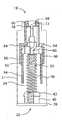
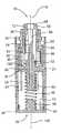
도 21 은 다른 실시 형태의 분해 등각도로서, 캡(206), 중공 하우징(211), 제 2 편향 부재(160)를 갖는 슬라이더(214), 바늘 홀더(216), 제 1 편향 부재(46) 및 기부(180)를 갖는다. 중공 하우징(211)은 공동부(186)를 규정하고, 근위 단부(18) 및 원위 단부(20)를 갖는다.FIG. 21 is an exploded isometric view of another embodiment, including a
슬라이더(214)는 적어도 부분적으로 중공 하우징(211)의 공동부(186)내에서 종축선(118)을 따라 외측 위치에서 밀린 위치까지 슬라이딩할 수 있다. 도 24 에서 보는 바와 같이, 슬라이더(214)는 외측 위치에 있을 때 중공 하우징(211)의 근위 단부(18)를 넘어 공동부(186)의 외측에서 연장되어 있다. 도 25 에서, 슬라이더(214)가 외측 위치에서 상기 밀린 위치까지 슬라이딩하면 바늘 홀더(216)가 전진 위치로 가게 된다.The
바늘 홀더(216)는 랜스(54)를 잡는다. 매우 유리한 특징에 따르면, 바늘 홀더(216)는 초기 위치에서 전진 위치로 이동하면 종축선(118) 주위로 회전가능하고 또한 그를 따라 병진 이동가능하다. 이러면, 랜스의 부주의한 작동 촉발의 가능성을 줄이는데 도움이 된다. 도 24 에서 보는 바와 같이, 바늘 홀더(216)가 초기 위치에 있으면, 슬라이더(214)는 외측 위치에 있게 된다. 바늘 홀더(216)가 전진 위치에 있으면, 도 25 에서 보는 바와 같이, 랜스(54)가 중공 하우징(211)의 근위 단부(18)를 넘어 공동부(186)의 외측에서 연장된다.
제 1 편향 부재(46)는 원위 단부(20)에서 중공 하우징(211) 내부에 배치된다. 슬라이더(214)가 상기 밀린 위치로 이동할 때 제 1 편향 부재(46)는 근위 단부(18) 쪽으로 편향력을 바늘 홀더(216)에 가하게 된다.The
도 21 은 제 2 편향 부재(160)를 나타낸다. 제 2 편향 부재(160)는 도 31 ? 32 에서 가장 잘 볼 수 있듯이, 탄성 밴드(162) 또는 다른 편향 부재일 수 있다. 탄성 밴드(162)는 휴지 상태에서 시작하여 바늘 홀더(216)가 전진 위치에 있을 때 그 바늘 홀더에 의해 연장 또는 신장되고, 바늘 홀더를 다시 후퇴 위치로 편향시켜 탄성 밴드를 휴지 위치로 복귀시키는 작용을 한다. 도 29 ? 31 에서 보는바와 같이, 슬라이더(214)는 외부에서 적어도 하나의 홈(164)을 갖는데, 이 홈안에는 상기 탄성 밴드(162)가 배치된다.21 shows a
바늘 홀더(216)는 한쌍의 외측 윙(166) 및 내측 윙(168)을 포함할 수 있다. 도 27 에서 보는 바와 같이, 바늘 홀더(216)의 외측 윙(166)은 내측 윙(168) 보다 중공 하우징(211)의 내벽에 더 가깝다. 외측 윙(166)은 선택적으로 경사질 수 있는데, 그러면 외측 윙은 슬라이더(214)와 슬라이딩가능하게 결합한다.The
바늘 홀더(216)가 전진 위치에 있고 랜스(54)가 공동부 밖으로 연장되어 있으면(그리고 선택적으로 환자의 피부(116) 안으로 침투해 있으면), 바늘 홀더(216)는 편향 조립체(12)의 편향력에 의해 다시 중공 하우징(211) 안으로 후퇴하게 될 것이다. 어떤 경우에는, 랜스(54)를 중공 하우징(211) 안으로 복귀시키기 위해 추가적인 편향력을 제공하는 것이 바람직하다.If the
탄성 밴드(162)는 유리하게도 바늘 홀더(216)를 다시 중공 하우징(211) 안으로 편향시키는 것을 도와 준다. 바늘 홀더(216)가 전진 위치에 있으면, 그 바늘 홀더(216)의 내측 윙(168)은 탄성 밴드(162)에 대해 밀린다. 탄성 밴드(162)가 과도하게 연장되면, 퍼텐셜 에너지가 축적되며, 이 에너지에 의해 바늘 홀더(216)가 전진 위치에서 후퇴 위치로 가게 된다. 후퇴 위치에서, 랜스(54)는 다시 중공 하우징(211) 안으로 후퇴된다. 이는 도 26 에서 볼 수 있다.
바늘 홀더(216)는 바늘 가드(172)를 더 포함한다. 랜스(54)는 바늘 가드(172) 내부에 배치된다. 캡(206)은 내부(188)를 규정한다(도 23 참조). 도 27 에는 바늘 가드(172)의 표면(174)이 나타나 있는데, 이 표면은 상기 내부(188)에 수용된다. 바늘 가드(172)의 표면(174)은 내부(188)에서 캡(206)과 결합한다. 캡을 비틀면 바늘 가드(172)를 쉽게 제거할 수 있다. 도 22 및 23 은 캡(206)을 바늘 홀더(16)에 어떻게 부착하는 가를 보여 준다. 나타나 있는 바와 같은 캡(206)과 바늘 가드(172)의 단면 형상이 효과적이다. 다른 형상도 본 개시의 이익을 얻는 당업자에게는 쉽게 명백할 것 이다.The
여러 다른 방법을 사용하여, 예컨대 캡(206)을 바늘 홀더(216)에 용접하거나, 접착제를 사용하거나, 또는 캡(206)의 구멍 안으로 클립될 수 있는 바늘 홀더(216)의 클립을 사용하여, 캡(206)을 바늘 홀더(216)에 부착할 수 있다.Using several other methods, for example, by welding the
도 28 은 중공 하우징(211)의 내벽(178)에 있는 멈춤 요소(176)를 나타낸다. 각각의 멈춤 요소(176)는 내벽(178)의 일체적인 연장부로서 형성될 수 있다. 멈춤 요소(176)로 인해, 원위 단부(20) 쪽으로의 슬라이더(214)의 이동이 억제되어, 랜스(54)가 슬라이더(214) 밖으로 또한 그래서 중공 하우징(211) 밖으로 돌출되는 것을 더 줄일 수 있다.28 shows the
란셋 장치(210)의 원위 단부(20)에 있는 기부(180)는 란셋 장치(210)를 폐쇄한다. 기부(180)와 바늘 홀더(216) 사이에는 스프링(46)이 배치된다. 이 스프링(46)은 스프링 홀더(182)에서 기부(180)에 부착된다.
특정 실시 형태의 전술한 개시와 상세한 설명으로부터, 본 발명의 범위와 요지를 벗어나지 않고 다양한 수정, 추가 및 다른 대안적인 실시형태가 가능함을 알 수 있을 것이다. 설명한 실시 형태는 본 발명의 원리와 그의 실제적인 적용에 대한 최선의 실례를 제공하여 당업자가 본 발명을 다양한 실시 형태로 또한 고려되는 특정 용도에 적합하게 다양하게 수정하여 사용할 수 있게 하기 위해 선택되고 설명된 것이다. 이러한 모든 수정과 변경도 공정히, 법적으로 또한 공평하게 부여 받는 범위에 따라 해석될 때 첨부된 청구범위으로 결정되는 본 발명의 범위에 속하는 것이다.From the foregoing disclosure and detailed description of specific embodiments, it will be appreciated that various modifications, additions, and other alternative embodiments are possible without departing from the scope and spirit of the invention. The described embodiments are selected and described in order to provide the best illustrative of the principles of the invention and its practical application to enable those skilled in the art to make various modifications and adaptations to suit the particular use contemplated by the present invention in various embodiments. It is. All such modifications and variations are intended to fall within the scope of the present invention as determined by the appended claims when interpreted in accordance with the fair, legal and equitable scope.
Claims (15)
Translated fromKorean공동부를 형성하고 근위 단부와 원위 단부를 갖는 중공 하우징;
적어도 부분적으로 중공 하우징의 공동부내에서 종축선을 따라 외측 위치에서 밀린 위치까지 슬라이딩할 수 있는 슬라이더;
바늘을 유지하며, 초기 위치에서 전진 위치로 움직일 때 상기 종축선 주위로 회전 및 그 종축선을 따라 병진 이동가능한 바늘 홀더;
원위 단부에서 중공 하우징내에 배치되며, 슬라이더가 상기 밀린 위치로 이동할 때 근위 단부쪽으로 편향력을 바늘 홀더에 가하게 되는 제 1 편향 부재; 및
제 2 편향 부재를 포함하며,
상기 슬라이더는 외측 위치에 있을 때 중공 하우징의 근위 단부를 넘어 공동부의 외부로 연장되며,
바늘 홀더가 초기 위치에 있을 때 슬라이더는 외측 위치에 있고, 바늘 홀더가 전진 위치에 있을 때 그 바늘 홀더는 중공 하우징의 근위 단부를 넘어 공동부의 외측으로 연장되며,
상기 슬라이더가 외측 위치에서 상기 밀린 위치로 슬라이딩하면 바늘 홀더가 전진 위치로 가게 되는 란셋 장치.As a lancet device,
A hollow housing forming a cavity and having a proximal end and a distal end;
A slider capable of sliding at least partially along the longitudinal axis from the outer position to the pushed position in the cavity of the hollow housing;
A needle holder that holds the needle and is rotatable about the longitudinal axis and translates along the longitudinal axis when moving from the initial position to the forward position;
A first biasing member disposed in the hollow housing at the distal end and adapted to apply a biasing force to the needle holder towards the proximal end when the slider moves to the pushed position; And
A second biasing member,
The slider extends out of the cavity beyond the proximal end of the hollow housing when in the outward position,
The slider is in the outward position when the needle holder is in the initial position, and the needle holder extends out of the cavity beyond the proximal end of the hollow housing when the needle holder is in the forward position,
And the needle holder moves to the forward position when the slider slides from the outer position to the pushed position.
상기 제 2 편향 부재는 슬라이더에 부착되는 탄성 밴드인 란셋 장치.The method of claim 1,
And the second biasing member is an elastic band attached to the slider.
상기 바늘 홀더가 전진 위치로 움직일 때 그 바늘 홀더는 제 2 편향 부재와 결합하여 후퇴 위치로 가게 되며, 이때 바늘은 공동부 안으로 다시 후퇴되는 란셋 장치.The method of claim 2,
And the needle holder engages with the second biasing member and moves to the retracted position when the needle holder is moved to the forward position, wherein the needle is retracted back into the cavity.
상기 슬라이더는 적어도 하나의 홈을 형성하고, 제 2 편향 부재는 그 홈에 배치되는 란셋 장치.The method of claim 1,
And the slider forms at least one groove, and the second biasing member is disposed in the groove.
상기 바늘 홀더는 한쌍의 외측 윙 및 한쌍의 내측 윙을 포함하며, 외측 윙은 내측 윙 보다 중공 하우징의 내벽에 더 가까운 란셋 장치.The method of claim 1,
The needle holder includes a pair of outer wings and a pair of inner wings, wherein the outer wing is closer to the inner wall of the hollow housing than the inner wing.
상기 바늘 홀더가 전진 위치에 있을 때 상기 내측 윙은 제 2 편향 부재와 결합하고, 그 제 2 편향 부재는 편향력을 가하여 바늘 홀더를 전진 위치에서 후퇴 위치로 보내며, 이때 바늘은 공동부 안으로 다시 후퇴되는 란셋 장치.The method of claim 5, wherein
When the needle holder is in the forward position the inner wing engages with the second biasing member, which second biasing member exerts a biasing force to direct the needle holder from the forward position to the retracted position, with the needle retracting back into the cavity. Lancet device.
상기 외측 윙은 슬라이더와 슬라이딩가능하게 결합하는 란셋 장치.The method of claim 5, wherein
And the outer wing slidably engages the slider.
내부를 형성하는 캡을 더 포함하고, 바늘 홀더는 바늘 주위에 배치되는 바늘 가드를 더 포함하며 이 가드는 상기 캡의 내부에 수용되는 란셋 장치.The method of claim 1,
And a cap defining an interior, the needle holder further comprising a needle guard disposed around the needle, the guard being received inside the cap.
상기 바늘 가드는 내부에서 캡과 결합하는 표면을 갖는 란셋 장치.The method of claim 8,
And the needle guard has a surface engaging with the cap therein.
캡 내부와 바늘 가드 표면 중의 일방은 원형 단면을 가지며, 캡 내부와 바늘 가드의 바늘 가드 표면 중의 타방은 비원형 단면을 갖는 란셋 장치.The method of claim 9,
One of the inside of the cap and the needle guard surface has a circular cross section, and the other of the inside of the cap and the needle guard surface of the needle guard has a non-circular cross section.
상기 캡은 접착제 또는 용접으로 바늘 홀더에 부착되는 란셋 장치.The method of claim 8,
And the cap is attached to the needle holder by adhesive or welding.
상기 중공 하우징은 이 중공 하우징의 내벽에 있는 일체적인 연장부로 형성된 적어도 하나의 멈춤 요소를 더 포함하고, 이 적어도 하나의 멈춤 요소는 슬라이더가 원위 단부쪽으로 움직이는 것을 억제하는 란셋 장치.The method of claim 1,
And the hollow housing further comprises at least one stop element formed of an integral extension on the inner wall of the hollow housing, the at least one stop element preventing the slider from moving towards the distal end.
외부 표면을 더 포함하고, 이 외부 표면은 중공 하우징의 외부 및 이 중공 하우징에 부착되는 일체적인 장식물 중의 하나를 포함하는 란셋 장치.The method of claim 1,
And an outer surface, the outer surface comprising one of an exterior of the hollow housing and an integral ornament attached to the hollow housing.
원위 단부에서 기부를 더 포함하고, 이 기부와 바늘 홀더 사이에는 상기 제 1 편향 부재가 배치되는 란셋 장치.The method of claim 1,
And a base at the distal end, wherein the first biasing member is disposed between the base and the needle holder.
스프링 홀더를 더 포함하고, 상기 제 1 편향 부재는 이 스프링 홀더에서 기부에 부착되는 스프링인 란셋 장치.15. The method of claim 14,
And a spring holder, said first biasing member being a spring attached to said base in said spring holder.
Applications Claiming Priority (3)
| Application Number | Priority Date | Filing Date | Title |
|---|---|---|---|
| US12/511,475US8317812B2 (en) | 2009-07-29 | 2009-07-29 | Lancet device with lance retraction |
| US12/511,475 | 2009-07-29 | ||
| PCT/SG2010/000231WO2011014125A1 (en) | 2009-07-29 | 2010-06-18 | Lancet device with lance retraction |
Publications (2)
| Publication Number | Publication Date |
|---|---|
| KR20120038457Atrue KR20120038457A (en) | 2012-04-23 |
| KR101791121B1 KR101791121B1 (en) | 2017-10-27 |
Family
ID=43527722
Family Applications (1)
| Application Number | Title | Priority Date | Filing Date |
|---|---|---|---|
| KR1020127002246AActiveKR101791121B1 (en) | 2009-07-29 | 2010-06-18 | Lancet device with lance retraction |
Country Status (12)
| Country | Link |
|---|---|
| US (2) | US8317812B2 (en) |
| EP (1) | EP2459067B1 (en) |
| JP (1) | JP5640084B2 (en) |
| KR (1) | KR101791121B1 (en) |
| CN (1) | CN101987016B (en) |
| AU (2) | AU2010277834A1 (en) |
| CA (1) | CA2768732C (en) |
| MX (1) | MX2012001206A (en) |
| MY (1) | MY169673A (en) |
| SG (1) | SG177566A1 (en) |
| TW (2) | TWI574709B (en) |
| WO (2) | WO2011014125A1 (en) |
Families Citing this family (35)
| Publication number | Priority date | Publication date | Assignee | Title |
|---|---|---|---|---|
| US20100256524A1 (en) | 2009-03-02 | 2010-10-07 | Seventh Sense Biosystems, Inc. | Techniques and devices associated with blood sampling |
| CN101816562B (en)* | 2010-04-22 | 2012-04-18 | 王琳 | Disposable automatic painless safe hemostix |
| US20130158482A1 (en) | 2010-07-26 | 2013-06-20 | Seventh Sense Biosystems, Inc. | Rapid delivery and/or receiving of fluids |
| WO2012021801A2 (en) | 2010-08-13 | 2012-02-16 | Seventh Sense Biosystems, Inc. | Systems and techniques for monitoring subjects |
| WO2012064802A1 (en) | 2010-11-09 | 2012-05-18 | Seventh Sense Biosystems, Inc. | Systems and interfaces for blood sampling |
| GB2489740A (en)* | 2011-04-08 | 2012-10-10 | Owen Mumford Ltd | Means for securely retaining a lancet in a lancing device |
| WO2012149155A1 (en) | 2011-04-29 | 2012-11-01 | Seventh Sense Biosystems, Inc. | Systems and methods for collecting fluid from a subject |
| KR102013466B1 (en)* | 2011-04-29 | 2019-08-22 | 세븐쓰 센스 바이오시스템즈, 인크. | Delivering and/or receiving fluids |
| CN103874461B (en) | 2011-04-29 | 2017-05-10 | 第七感生物系统有限公司 | Devices for collecting and/or manipulating blood spots or other bodily fluids |
| US20130211289A1 (en) | 2012-01-25 | 2013-08-15 | Tasso, Inc. | Handheld Device for Drawing, Collecting, and Analyzing Bodily Fluid |
| JP6420764B2 (en)* | 2012-08-27 | 2018-11-07 | ファセット テクノロジーズ エルエルシーFacet Technologies, LLC | Twist loading mechanism of puncture device |
| CN102871672B (en)* | 2012-09-29 | 2014-12-10 | 苏州施莱医疗器械有限公司 | Detachable cap-type adjusting head of lancing device |
| TWI569843B (en)* | 2012-12-14 | 2017-02-11 | 伸縮科技股份有限公司 | Needle retraction apparatus |
| CN103211601B (en)* | 2013-04-09 | 2014-12-10 | 苏州市玮琪生物科技有限公司 | Blood taking needle |
| EP3007621B1 (en)* | 2013-06-13 | 2017-12-06 | Roche Diabetes Care GmbH | Body fluid sampling element |
| GB2521150B (en)* | 2013-12-10 | 2016-04-27 | Owen Mumford Ltd | Skin pricking lancets |
| USD782665S1 (en)* | 2014-01-28 | 2017-03-28 | Medline Industries, Inc. | Connector |
| USD760384S1 (en)* | 2014-03-31 | 2016-06-28 | Sekisui Medical Co., Ltd. | Cap for a blood collection tube |
| CN106999120B (en) | 2014-08-01 | 2021-05-14 | 塔索公司 | Devices, systems, and methods for gravity-enhanced microfluidic collection, handling, and delivery of liquids |
| TWI571635B (en)* | 2014-11-07 | 2017-02-21 | 光寶電子(廣州)有限公司 | Blood glucose detecting device |
| ES2867775T3 (en)* | 2015-03-26 | 2021-10-20 | Enable Injections Inc | Apparatus and method of transfer and resuspension of medicines by gas under pressure |
| CA3009328C (en) | 2015-12-21 | 2024-03-05 | Tasso, Inc. | Devices, systems and methods for actuation and retraction in fluid collection |
| CN106166082B (en)* | 2016-08-26 | 2018-08-17 | 任飞 | From retraction puncture outfit |
| CN108272461B (en)* | 2017-01-06 | 2020-07-31 | 天津华鸿科技股份有限公司 | lancet |
| JP7460607B2 (en) | 2018-09-14 | 2024-04-02 | タッソ インコーポレイテッド | Body fluid collection devices and related methods |
| SE542496C2 (en)* | 2018-09-20 | 2020-05-26 | Ind Stockholm Ab | Improved activation and retraction mechanism for lancing devices |
| GB2577869A (en)* | 2018-09-28 | 2020-04-15 | Owen Mumford Ltd | A blood sampling device |
| CN109259773B (en)* | 2018-10-19 | 2024-06-11 | 宁波美生医疗器材有限公司 | Push type blood taking needle |
| CN109938746B (en)* | 2019-03-29 | 2021-10-15 | 西安医学院 | A high-safety puncture needle |
| CN111067598B (en)* | 2019-12-19 | 2025-07-01 | 北京派尔特医疗科技股份有限公司 | A radiofrequency puncture needle |
| WO2022103325A1 (en)* | 2020-11-16 | 2022-05-19 | Medipurpose Pte. Ltd. | Lancet assembly |
| CN113384358B (en)* | 2021-05-19 | 2022-05-03 | 四川大学华西医院 | A Portable Recycling One Pain Examination Tool |
| CN115475324B (en)* | 2021-06-16 | 2025-09-16 | 苏州悦肤达医疗科技有限公司 | Needle aid and medical device |
| US12246156B2 (en)* | 2022-02-28 | 2025-03-11 | Long Xiao | Needle assembly for liquid applicator |
| USD1031037S1 (en) | 2022-04-13 | 2024-06-11 | Micro Lab Solutions, Llc | Safety lancet |
Family Cites Families (36)
| Publication number | Priority date | Publication date | Assignee | Title |
|---|---|---|---|---|
| DE2642896C3 (en)* | 1976-09-24 | 1980-08-21 | 7800 Freiburg | Precision snapper for setting standard stab wounds in the skin for diagnostic purposes |
| US4375815A (en)* | 1981-03-23 | 1983-03-08 | Becton Dickinson And Company | Retractable lancet assembly |
| FR2508305B1 (en)* | 1981-06-25 | 1986-04-11 | Slama Gerard | DEVICE FOR CAUSING A LITTLE BITE TO COLLECT A BLOOD DROP |
| US4445510A (en)* | 1982-09-13 | 1984-05-01 | Rigby Ronald F | Automatic injector for hypodermic syringes or the like and lancet holder for use in conjunction with an automatic injector |
| US4628929A (en)* | 1985-08-16 | 1986-12-16 | American Hospital Supply Corporation | Retractable blade bleeding time device |
| US4735203A (en)* | 1986-12-12 | 1988-04-05 | Ryder International Corporation | Retractable lancet |
| US5196025A (en)* | 1990-05-21 | 1993-03-23 | Ryder International Corporation | Lancet actuator with retractable mechanism |
| US5133730A (en)* | 1991-05-15 | 1992-07-28 | International Technidyne Corporation | Disposable-retractable finger stick device |
| US5402798A (en)* | 1991-07-18 | 1995-04-04 | Swierczek; Remi | Disposable skin perforator and blood testing device |
| US5643306A (en)* | 1996-03-22 | 1997-07-01 | Stat Medical Devices Inc. | Disposable lancet |
| US5613978A (en)* | 1996-06-04 | 1997-03-25 | Palco Laboratories | Adjustable tip for lancet device |
| US5741288A (en)* | 1996-06-27 | 1998-04-21 | Chemtrak, Inc. | Re-armable single-user safety finger stick device having reset for multiple use by a single patient |
| US5984940A (en)* | 1997-05-29 | 1999-11-16 | Atrion Medical Products, Inc. | Lancet device |
| US5797940A (en)* | 1997-05-30 | 1998-08-25 | International Technidyne Corporation | Adjustable skin incision device |
| US6056765A (en)* | 1997-06-24 | 2000-05-02 | Bajaj; Ratan | Lancet device |
| US5964718A (en)* | 1997-11-21 | 1999-10-12 | Mercury Diagnostics, Inc. | Body fluid sampling device |
| US7175641B1 (en)* | 1998-06-11 | 2007-02-13 | Stat Medical Devices, Inc. | Lancet having adjustable penetration depth |
| DE19830604C2 (en)* | 1998-07-09 | 2000-06-21 | November Ag Molekulare Medizin | Device for perforating skin |
| USD526409S1 (en)* | 1998-07-14 | 2006-08-08 | Unomedical A/S | Medical puncturing device |
| JP3361470B2 (en)* | 1999-03-02 | 2003-01-07 | アプルス株式会社 | Lancet device for forming precisely controlled incidents |
| US6306152B1 (en)* | 1999-03-08 | 2001-10-23 | Agilent Technologies, Inc. | Lancet device with skin movement control and ballistic preload |
| SG85117A1 (en)* | 1999-06-18 | 2001-12-19 | Surgilance Pte Ltd | Lancet assembly |
| USD449687S1 (en)* | 2000-08-31 | 2001-10-23 | Disetronic Licensing Ag | Needle shield for an injection device |
| US6540763B2 (en)* | 2001-02-20 | 2003-04-01 | Medisys Asia Pacific Pte Ltd. | Lancet device with retractable sharps member |
| CN1332632C (en)* | 2001-07-11 | 2007-08-22 | 爱科来株式会社 | Lancets and Piercing Devices |
| US7374544B2 (en)* | 2002-04-19 | 2008-05-20 | Pelikan Technologies, Inc. | Method and apparatus for penetrating tissue |
| US20030143113A2 (en)* | 2002-05-09 | 2003-07-31 | Lifescan, Inc. | Physiological sample collection devices and methods of using the same |
| US7105006B2 (en)* | 2003-08-15 | 2006-09-12 | Stat Medical Devices, Inc. | Adjustable lancet device and method |
| RU2006138486A (en)* | 2004-04-01 | 2008-05-10 | БАЙЕР ХЕЛТКЭР ЭлЭлСи (US) | TIP FOR VACUUM PUNCHING APPLIANCES |
| KR101121072B1 (en) | 2004-05-07 | 2012-03-15 | 벡톤 디킨슨 앤드 컴퍼니 | Contact activated lancet device |
| ES2746309T3 (en)* | 2004-05-07 | 2020-03-05 | Becton Dickinson Co | Cam Powered Medical Puncture Device |
| JP2006020934A (en)* | 2004-07-09 | 2006-01-26 | Nipro Corp | Blood collection needle |
| PL2425776T3 (en)* | 2005-04-07 | 2013-12-31 | Becton Dickinson Co | Lancet device |
| DE502006001024D1 (en)* | 2006-01-10 | 2008-08-14 | Roche Diagnostics Gmbh | Lancing device with reuse protection |
| US8043318B2 (en)* | 2007-02-08 | 2011-10-25 | Stat Medical Devices, Inc. | Push-button lance device and method |
| SG152088A1 (en)* | 2007-10-24 | 2009-05-29 | Joseph Lum Wah Leong | Lancet device |
- 2009
- 2009-07-29USUS12/511,475patent/US8317812B2/ennot_activeExpired - Fee Related
- 2009-12-22MYMYPI20095513Apatent/MY169673A/enunknown
- 2010
- 2010-02-05CNCN201010112483.6Apatent/CN101987016B/ennot_activeExpired - Fee Related
- 2010-06-18CACA2768732Apatent/CA2768732C/enactiveActive
- 2010-06-18AUAU2010277834Apatent/AU2010277834A1/ennot_activeAbandoned
- 2010-06-18KRKR1020127002246Apatent/KR101791121B1/enactiveActive
- 2010-06-18JPJP2012522781Apatent/JP5640084B2/enactiveActive
- 2010-06-18SGSG2012001327Apatent/SG177566A1/enunknown
- 2010-06-18MXMX2012001206Apatent/MX2012001206A/enactiveIP Right Grant
- 2010-06-18EPEP10804798.6Apatent/EP2459067B1/ennot_activeNot-in-force
- 2010-06-18WOPCT/SG2010/000231patent/WO2011014125A1/enactiveApplication Filing
- 2010-06-22TWTW099120298Apatent/TWI574709B/ennot_activeIP Right Cessation
- 2010-07-23WOPCT/SG2010/000279patent/WO2011014126A1/enactiveApplication Filing
- 2010-07-26TWTW099124593Apatent/TWI574669B/ennot_activeIP Right Cessation
- 2012
- 2012-10-18USUS13/654,517patent/US8882794B2/enactiveActive
- 2016
- 2016-01-11AUAU2016200151Apatent/AU2016200151B2/enactiveActive
Also Published As
| Publication number | Publication date |
|---|---|
| TW201105295A (en) | 2011-02-16 |
| JP5640084B2 (en) | 2014-12-10 |
| US8882794B2 (en) | 2014-11-11 |
| TWI574669B (en) | 2017-03-21 |
| CA2768732C (en) | 2018-03-06 |
| EP2459067B1 (en) | 2014-04-23 |
| KR101791121B1 (en) | 2017-10-27 |
| MX2012001206A (en) | 2012-06-12 |
| WO2011014126A1 (en) | 2011-02-03 |
| AU2016200151A1 (en) | 2016-02-04 |
| MY169673A (en) | 2019-05-09 |
| EP2459067A4 (en) | 2012-12-05 |
| EP2459067A1 (en) | 2012-06-06 |
| AU2010277834A1 (en) | 2012-02-16 |
| CN101987016B (en) | 2015-08-05 |
| CN101987016A (en) | 2011-03-23 |
| SG177566A1 (en) | 2012-02-28 |
| JP2013500123A (en) | 2013-01-07 |
| TWI574709B (en) | 2017-03-21 |
| AU2016200151B2 (en) | 2017-06-15 |
| WO2011014125A1 (en) | 2011-02-03 |
| TW201105377A (en) | 2011-02-16 |
| US8317812B2 (en) | 2012-11-27 |
| CA2768732A1 (en) | 2011-02-03 |
| US20110029006A1 (en) | 2011-02-03 |
| US20130041393A1 (en) | 2013-02-14 |
Similar Documents
| Publication | Publication Date | Title |
|---|---|---|
| KR20120038457A (en) | Lancet device with lance retraction | |
| US8858582B2 (en) | Push activation lancet device | |
| CN101849830B (en) | Contact activated lancet device | |
| CN101184444B (en) | Lancet device | |
| EP1755455B1 (en) | Rotary-actuated medical puncturing device | |
| JP2012501800A (en) | Safety needle assembly and method | |
| KR101170757B1 (en) | Cam-actuated medical puncturing device and method |
Legal Events
| Date | Code | Title | Description |
|---|---|---|---|
| PA0105 | International application | Patent event date:20120127 Patent event code:PA01051R01D Comment text:International Patent Application | |
| PG1501 | Laying open of application | ||
| A201 | Request for examination | ||
| PA0201 | Request for examination | Patent event code:PA02012R01D Patent event date:20150615 Comment text:Request for Examination of Application | |
| E902 | Notification of reason for refusal | ||
| PE0902 | Notice of grounds for rejection | Comment text:Notification of reason for refusal Patent event date:20160816 Patent event code:PE09021S01D | |
| E90F | Notification of reason for final refusal | ||
| PE0902 | Notice of grounds for rejection | Comment text:Final Notice of Reason for Refusal Patent event date:20170214 Patent event code:PE09021S02D | |
| E701 | Decision to grant or registration of patent right | ||
| PE0701 | Decision of registration | Patent event code:PE07011S01D Comment text:Decision to Grant Registration Patent event date:20170726 | |
| GRNT | Written decision to grant | ||
| PR0701 | Registration of establishment | Comment text:Registration of Establishment Patent event date:20171023 Patent event code:PR07011E01D | |
| PR1002 | Payment of registration fee | Payment date:20171023 End annual number:3 Start annual number:1 | |
| PG1601 | Publication of registration | ||
| PR1001 | Payment of annual fee | Payment date:20201022 Start annual number:4 End annual number:4 | |
| PR1001 | Payment of annual fee | Payment date:20211026 Start annual number:5 End annual number:5 | |
| PR1001 | Payment of annual fee | Payment date:20241014 Start annual number:8 End annual number:8 |