KR20120035924A - Base station, communication system, mobile terminal, and relay station - Google Patents
Base station, communication system, mobile terminal, and relay stationDownload PDFInfo
- Publication number
- KR20120035924A KR20120035924AKR1020127001328AKR20127001328AKR20120035924AKR 20120035924 AKR20120035924 AKR 20120035924AKR 1020127001328 AKR1020127001328 AKR 1020127001328AKR 20127001328 AKR20127001328 AKR 20127001328AKR 20120035924 AKR20120035924 AKR 20120035924A
- Authority
- KR
- South Korea
- Prior art keywords
- link
- relay
- frequency
- mobile terminal
- base station
- Prior art date
- Legal status (The legal status is an assumption and is not a legal conclusion. Google has not performed a legal analysis and makes no representation as to the accuracy of the status listed.)
- Withdrawn
Links
- 238000004891communicationMethods0.000titleclaimsabstractdescription79
- 238000000034methodMethods0.000claimsdescription14
- 230000001934delayEffects0.000abstract1
- 238000012545processingMethods0.000description47
- 238000010586diagramMethods0.000description36
- 230000005540biological transmissionEffects0.000description25
- 238000006243chemical reactionMethods0.000description13
- 230000003139buffering effectEffects0.000description6
- 230000004048modificationEffects0.000description4
- 238000012986modificationMethods0.000description4
- 230000003321amplificationEffects0.000description3
- 238000012937correctionMethods0.000description3
- 238000001914filtrationMethods0.000description3
- 238000003199nucleic acid amplification methodMethods0.000description3
- 230000010355oscillationEffects0.000description2
- 230000008569processEffects0.000description2
- 230000008901benefitEffects0.000description1
- 230000008859changeEffects0.000description1
- 230000002860competitive effectEffects0.000description1
- 230000006872improvementEffects0.000description1
- 230000007774longtermEffects0.000description1
- 238000010422paintingMethods0.000description1
Images


Classifications
- H—ELECTRICITY
- H04—ELECTRIC COMMUNICATION TECHNIQUE
- H04B—TRANSMISSION
- H04B7/00—Radio transmission systems, i.e. using radiation field
- H04B7/14—Relay systems
- H04B7/15—Active relay systems
- H04B7/155—Ground-based stations
- H04B7/15528—Control of operation parameters of a relay station to exploit the physical medium
- H04B7/15542—Selecting at relay station its transmit and receive resources
- H—ELECTRICITY
- H04—ELECTRIC COMMUNICATION TECHNIQUE
- H04W—WIRELESS COMMUNICATION NETWORKS
- H04W72/00—Local resource management
- H04W72/20—Control channels or signalling for resource management
- H—ELECTRICITY
- H04—ELECTRIC COMMUNICATION TECHNIQUE
- H04B—TRANSMISSION
- H04B7/00—Radio transmission systems, i.e. using radiation field
- H04B7/14—Relay systems
- H04B7/15—Active relay systems
- H—ELECTRICITY
- H04—ELECTRIC COMMUNICATION TECHNIQUE
- H04B—TRANSMISSION
- H04B7/00—Radio transmission systems, i.e. using radiation field
- H04B7/14—Relay systems
- H04B7/15—Active relay systems
- H04B7/155—Ground-based stations
- H—ELECTRICITY
- H04—ELECTRIC COMMUNICATION TECHNIQUE
- H04W—WIRELESS COMMUNICATION NETWORKS
- H04W16/00—Network planning, e.g. coverage or traffic planning tools; Network deployment, e.g. resource partitioning or cells structures
- H04W16/24—Cell structures
- H04W16/26—Cell enhancers or enhancement, e.g. for tunnels, building shadow
- H—ELECTRICITY
- H04—ELECTRIC COMMUNICATION TECHNIQUE
- H04W—WIRELESS COMMUNICATION NETWORKS
- H04W72/00—Local resource management
- H04W72/12—Wireless traffic scheduling
- H04W72/1263—Mapping of traffic onto schedule, e.g. scheduled allocation or multiplexing of flows
- H04W72/1268—Mapping of traffic onto schedule, e.g. scheduled allocation or multiplexing of flows of uplink data flows
- H—ELECTRICITY
- H04—ELECTRIC COMMUNICATION TECHNIQUE
- H04W—WIRELESS COMMUNICATION NETWORKS
- H04W88/00—Devices specially adapted for wireless communication networks, e.g. terminals, base stations or access point devices
- H04W88/02—Terminal devices
- H—ELECTRICITY
- H04—ELECTRIC COMMUNICATION TECHNIQUE
- H04W—WIRELESS COMMUNICATION NETWORKS
- H04W88/00—Devices specially adapted for wireless communication networks, e.g. terminals, base stations or access point devices
- H04W88/08—Access point devices
- H—ELECTRICITY
- H04—ELECTRIC COMMUNICATION TECHNIQUE
- H04B—TRANSMISSION
- H04B7/00—Radio transmission systems, i.e. using radiation field
- H04B7/14—Relay systems
- H04B7/15—Active relay systems
- H04B7/155—Ground-based stations
- H04B7/15557—Selecting relay station operation mode, e.g. between amplify and forward mode, decode and forward mode or FDD - and TDD mode
- H—ELECTRICITY
- H04—ELECTRIC COMMUNICATION TECHNIQUE
- H04B—TRANSMISSION
- H04B7/00—Radio transmission systems, i.e. using radiation field
- H04B7/24—Radio transmission systems, i.e. using radiation field for communication between two or more posts
- H04B7/26—Radio transmission systems, i.e. using radiation field for communication between two or more posts at least one of which is mobile
- H04B7/2603—Arrangements for wireless physical layer control
- H04B7/2606—Arrangements for base station coverage control, e.g. by using relays in tunnels
- H—ELECTRICITY
- H04—ELECTRIC COMMUNICATION TECHNIQUE
- H04W—WIRELESS COMMUNICATION NETWORKS
- H04W72/00—Local resource management
- H04W72/12—Wireless traffic scheduling
- H04W72/1263—Mapping of traffic onto schedule, e.g. scheduled allocation or multiplexing of flows
- H04W72/1273—Mapping of traffic onto schedule, e.g. scheduled allocation or multiplexing of flows of downlink data flows
- H—ELECTRICITY
- H04—ELECTRIC COMMUNICATION TECHNIQUE
- H04W—WIRELESS COMMUNICATION NETWORKS
- H04W72/00—Local resource management
- H04W72/50—Allocation or scheduling criteria for wireless resources
- H04W72/535—Allocation or scheduling criteria for wireless resources based on resource usage policies
- H—ELECTRICITY
- H04—ELECTRIC COMMUNICATION TECHNIQUE
- H04W—WIRELESS COMMUNICATION NETWORKS
- H04W84/00—Network topologies
- H04W84/02—Hierarchically pre-organised networks, e.g. paging networks, cellular networks, WLAN [Wireless Local Area Network] or WLL [Wireless Local Loop]
- H04W84/04—Large scale networks; Deep hierarchical networks
- H04W84/042—Public Land Mobile systems, e.g. cellular systems
- H04W84/047—Public Land Mobile systems, e.g. cellular systems using dedicated repeater stations
Landscapes
- Engineering & Computer Science (AREA)
- Computer Networks & Wireless Communication (AREA)
- Signal Processing (AREA)
- Mobile Radio Communication Systems (AREA)
Abstract
Translated fromKoreanDescription
Translated fromKorean본 발명은 기지국, 통신 시스템, 이동 단말기 및 중계 장치에 관한 것이다.The present invention relates to a base station, a communication system, a mobile terminal and a relay device.
3GPP(Third Generation Partnership Project)에 있어서, 셀 엣지에서의 스루풋의 향상을 실현하기 위해, 중계 장치(릴레이 스테이션)를 이용하는 기술이 활발히 검토되고 있다.In the 3GPP (Third Generation Partnership Project), a technique using a relay device (relay station) has been actively studied in order to realize an improvement in throughput at the cell edge.
이 중계 장치는, 다운 링크에 있어서, 기지국으로부터 송신된 신호를 수신하여 증폭한 뒤, 증폭한 신호를 이동 단말기에 대하여 송신한다. 중계 장치는, 이러한 중계를 행함으로써, 기지국으로부터 이동 단말기에 대하여 신호를 직접 송신하는 경우보다도 신호 대 잡음비를 높게 하는 것이 가능하다. 마찬가지로, 중계 장치는 업 링크에서도, 이동 단말기로부터 송신된 신호를 기지국에 중계함으로써, 신호 대 잡음비를 높게 유지할 수 있다. 또한, 중계 장치에 의한 이러한 중계에 대해서는 예를 들어 비특허문헌 1에 기재되어 있다.This relay device receives and amplifies a signal transmitted from a base station in the downlink, and then transmits the amplified signal to the mobile terminal. By performing such a relay, the relay device can make the signal-to-noise ratio higher than when the signal is directly transmitted from the base station to the mobile terminal. Similarly, the relay device can keep the signal-to-noise ratio high by relaying the signal transmitted from the mobile terminal to the base station even in the uplink. In addition, about this relay by a relay apparatus, it is described in the
또한, 중계 장치에 의한 중계 방식으로서, Amp-Forward형, Decode-Forward형 등을 들 수 있다. Amp-Forward형은, 수신한 신호를 아날로그 신호 그대로 증폭해서 송신하는 방식이다. 이 Amp-Forward형에서는, 신호 대 잡음비가 개선되지 않지만, 통신 프로토콜을 개량하지 않아도 된다는 이점을 갖는다. 또한, 중계 장치는 송신 안테나와 수신 안테나 사이에 피드백 경로를 갖기 때문에, 이 피드백 경로가 발진하지 않도록 설계된다.Moreover, Amp-Forward type, Decode-Forward type, etc. are mentioned as a relay system by a relay apparatus. The Amp-Forward type amplifies and transmits the received signal as it is. In this Amp-Forward type, the signal-to-noise ratio is not improved, but there is an advantage that the communication protocol does not have to be improved. In addition, since the relay device has a feedback path between the transmitting antenna and the receiving antenna, it is designed so that this feedback path does not oscillate.
Decode-Forward형은, 수신한 신호를 AD 변환에 의해서 디지털 신호로 변환하고, 디지털 신호에 대하여 오류 정정 등의 디코드를 행하고, 디코드된 디지털 신호를 다시 인코드하고, 디지털 신호를 DA 변환에 의해서 아날로그 신호로 변환하고, 아날로그 신호를 증폭해서 송신하는 방식이다. Decode-Forward형에서는, 부호화 이득에 의해 신호 대 잡음비를 개선하는 것이 가능하다. 또한, 중계 장치는, 수신에 의해 얻어진 디지털 신호를 메모리에 축적하고, 디지털 신호를 다음 타임 슬롯으로 송신함으로써, 송신 안테나와 수신 안테나간의 피드백 회로의 발진을 피할 수 있다. 또한, 중계 장치는 타임 슬롯이 아닌, 주파수를 바꿈으로써 발진을 피하는 것도 가능하다.The decode-forward type converts the received signal into a digital signal by AD conversion, decodes error correction, etc. on the digital signal, encodes the decoded digital signal again, and converts the digital signal into an analog by DA conversion. It converts the signal and amplifies and transmits the analog signal. In the decode-forward type, the signal-to-noise ratio can be improved by the coding gain. In addition, the relay device can avoid oscillation of the feedback circuit between the transmitting antenna and the receiving antenna by accumulating the digital signal obtained by the reception in a memory and transmitting the digital signal in the next time slot. In addition, the relay device may avoid oscillation by changing the frequency rather than the time slot.
한편, LTE(Long Term Evolution)나 LTE-Advanced에서는, 유저간의 통신 지연을 적게 하는 것(예를 들어, 50ms 이하)이 요구되고 있다. 그러나, 기지국과 이동 단말기 사이에 중계 장치를 설치하면, 중계 장치에서 지연이 발생하기 때문에, 지연에 관한 문제는 보다 중요해진다.On the other hand, in LTE (Long Term Evolution) and LTE-Advanced, it is required to reduce the communication delay between users (for example, 50 ms or less). However, when a relay device is provided between the base station and the mobile terminal, a delay occurs in the relay device, so that the problem of delay becomes more important.
따라서, 본 발명은 상기 문제를 감안하여 이루어진 것으로, 본 발명이 목적으로 하는 점은, 지연 특성이 상이한 복수의 링크 할당 패턴 중 어느 하나에 따라 각 링크를 주파수-시간 블록에 할당하는 것이 가능한, 신규이며 개량된 기지국, 통신 시스템, 이동 단말기 및 중계 장치를 제공하는 것에 있다.Accordingly, the present invention has been made in view of the above problems, and an object of the present invention is to provide a novel method in which each link can be allocated to a frequency-time block according to any one of a plurality of link allocation patterns having different delay characteristics. The present invention provides an improved base station, communication system, mobile terminal, and relay device.
상기 과제를 해결하기 위해서, 본 발명의 어느 한 관점에 의하면, 기지국으로서, 상기 기지국과 중계 장치 사이의 릴레이 링크 및 상기 중계 장치와 이동 단말기 사이의 액세스 링크를 통해 상기 이동 단말기와 통신하는 통신부와, 상기 릴레이 링크의 업 링크, 상기 릴레이 링크의 다운 링크, 상기 액세스 링크의 업 링크 및 상기 액세스 링크의 다운 링크의 주파수-시간 블록에의 할당 패턴을, 상기 기지국과 상기 이동 단말기 사이에서 발생하는 지연 특성이 상이한 복수의 할당 패턴으로부터 선택하는 선택부를 구비하는 기지국이 제공된다.In order to solve the above problems, according to one aspect of the present invention, there is provided a base station comprising: a communication unit communicating with the mobile terminal via a relay link between the base station and the relay device and an access link between the relay device and the mobile terminal; A delay characteristic generated between the base station and the mobile terminal, the allocation pattern of the uplink of the relay link, the downlink of the relay link, the uplink of the access link, and the frequency-time block of the downlink of the access link; A base station having a selector for selecting from a plurality of different allocation patterns is provided.
상기 통신부는, 상기 중계 장치가 대응 가능한 할당 패턴을 나타내는 정보를 수신하고, 상기 선택부는, 상기 복수의 할당 패턴으로부터 상기 중계 장치가 대응 가능한 할당 패턴을 선택해도 좋다.The communication unit may receive information indicating an allocation pattern to which the relay device can correspond, and the selection unit may select an allocation pattern to which the relay device can correspond from the plurality of allocation patterns.
상기 선택부는, 상기 기지국과 상기 이동 단말기 사이의 통신에 요구되는 지연 특성에 따라 상기 할당 패턴을 선택해도 좋다.The selection unit may select the allocation pattern in accordance with a delay characteristic required for communication between the base station and the mobile terminal.
하나의 무선 프레임이 복수의 서브 프레임에 의해 구성되며, 상기 주파수-시간 블록의 각각의 시간대는 서브 프레임의 시간대에 대응해도 좋다.One radio frame is composed of a plurality of subframes, and each time zone of the frequency-time block may correspond to a time zone of the subframe.
하나의 무선 프레임이 복수 슬롯으로 이루어지는 복수의 서브 프레임에 의해 구성되어 있고,One radio frame is composed of a plurality of subframes consisting of a plurality of slots,
상기 주파수-시간 블록의 각각의 시간대는, 슬롯의 시간대에 대응해도 좋다.Each time zone of the frequency-time block may correspond to a time zone of the slot.
상기 복수의 할당 패턴은, 상기 릴레이 링크의 다운 링크와 상기 액세스 링크의 다운 링크의 주파수-시간 블록의 시간이 상이하고, 상기 액세스 링크의 업 링크와 상기 릴레이 링크의 업 링크의 주파수-시간 블록의 시간이 상이한 할당 패턴과, 상기 릴레이 링크의 다운 링크와 상기 액세스 링크의 다운 링크의 주파수-시간 블록의 주파수가 상이하며, 상기 액세스 링크의 업 링크와 상기 릴레이 링크의 업 링크의 주파수-시간 블록의 주파수가 상이한 할당 패턴을 포함하여도 된다.The plurality of allocation patterns are different in time of frequency-time blocks of the downlink of the relay link and the downlink of the access link, and include the frequency-time blocks of the uplink of the access link and the uplink of the relay link. The allocation pattern differs in time, and the frequencies of the frequency-time blocks of the downlink of the relay link and the downlink of the access link are different, and the frequency-time blocks of the uplink of the access link and the uplink of the relay link are different. It is also possible to include allocation patterns with different frequencies.
상기 복수의 할당 패턴은, 상기 릴레이 링크의 업 링크, 상기 릴레이 링크의 다운 링크, 상기 액세스 링크의 업 링크 및 상기 액세스 링크의 다운 링크의 주파수-시간 블록의 시간이 동일하고 주파수가 상이한 할당 패턴을 포함하여도 된다.The plurality of allocation patterns may include allocation patterns having the same time and different frequencies in frequency-time blocks of the uplink of the relay link, the downlink of the relay link, the uplink of the access link, and the downlink of the access link. You may include it.
상기 복수의 할당 패턴은, 상기 릴레이 링크의 업 링크, 상기 릴레이 링크의 다운 링크, 상기 액세스 링크의 업 링크 및 상기 액세스 링크의 다운 링크의 주파수-시간 블록의 주파수가 동일하고 시간이 상이한 할당 패턴을 포함하여도 된다.The plurality of allocation patterns may include allocation patterns having the same frequency and different time in frequency-time blocks of the uplink of the relay link, the downlink of the relay link, the uplink of the access link, and the downlink of the access link. You may include it.
상기 복수의 할당 패턴은, 상기 릴레이 링크의 다운 링크와 상기 액세스 링크의 다운 링크의 주파수-시간 블록의 시간 및 주파수가 상이하고, 상기 액세스 링크의 업 링크와 상기 릴레이 링크의 업 링크의 주파수-시간 블록의 시간 및 주파수가 상이한 할당 패턴을 포함하여도 된다.The plurality of allocation patterns are different in time and frequency of the frequency-time block of the downlink of the relay link and the downlink of the access link, and the frequency-time of the uplink of the access link and the uplink of the relay link. The time and frequency of the block may include different allocation patterns.
또한, 상기 과제를 해결하기 위해서, 본 발명의 다른 관점에 의하면, 이동 단말기와, 중계 장치와, 기지국으로서, 상기 기지국과 상기 중계 장치 사이의 릴레이 링크 및 상기 중계 장치와 상기 이동 단말기 사이의 액세스 링크를 통해 상기 이동 단말기와 통신하는 통신부, 및 상기 릴레이 링크의 업 링크, 상기 릴레이 링크의 다운 링크, 상기 액세스 링크의 업 링크 및 상기 액세스 링크의 다운 링크의 주파수-시간 블록에의 할당 패턴을, 상기 기지국과 상기 이동 단말기 사이에서 발생하는 지연 특성이 상이한 복수의 할당 패턴으로부터 선택하는 선택부를 갖는 기지국을 구비하는 통신 시스템이 제공된다.Further, in order to solve the above problem, according to another aspect of the present invention, as a mobile terminal, a relay device, and a base station, a relay link between the base station and the relay device and an access link between the relay device and the mobile terminal A communication unit for communicating with the mobile terminal through an assignment pattern of uplink of the relay link, downlink of the relay link, uplink of the access link, and frequency-time block of the downlink of the access link, A communication system is provided having a base station having a selection unit for selecting from a plurality of allocation patterns having different delay characteristics occurring between the base station and the mobile terminal.
또한, 상기 과제를 해결하기 위해서, 본 발명의 다른 관점에 의하면, 이동 단말기이며, 기지국과 중계 장치 사이의 릴레이 링크 및 상기 중계 장치와 상기 이동 단말기 사이의 액세스 링크를 통해 상기 이동 단말기와 통신하는 통신부, 및 상기 릴레이 링크의 업 링크, 상기 릴레이 링크의 다운 링크, 상기 액세스 링크의 업 링크 및 상기 액세스 링크의 다운 링크의 주파수-시간 블록에의 할당 패턴을, 상기 기지국과 상기 이동 단말기 사이에서 발생하는 지연 특성이 상이한 복수의 할당 패턴으로부터 선택하는 선택부를 갖는 상기 기지국과, 상기 선택부에 의해 선택된 할당 패턴에 따라서 상기 중계 장치를 통해 통신하는 이동 단말기가 제공된다.In addition, in order to solve the above problem, according to another aspect of the present invention, a communication unit which is a mobile terminal and communicates with the mobile terminal through a relay link between a base station and a relay device and an access link between the relay device and the mobile terminal. And assigning patterns to frequency-time blocks of the uplink of the relay link, the downlink of the relay link, the uplink of the access link, and the downlink of the access link, between the base station and the mobile terminal. A base station having a selection unit for selecting from a plurality of allocation patterns having different delay characteristics and a mobile terminal for communicating through the relay apparatus in accordance with the allocation pattern selected by the selection unit are provided.
또한, 상기 과제를 해결하기 위해서, 본 발명의 다른 관점에 의하면, 중계 장치로서, 기지국과 상기 중계 장치 사이의 릴레이 링크 및 상기 중계 장치와 상기 이동 단말기 사이의 액세스 링크를 통해 상기 이동 단말기와 통신하는 통신부, 및 상기 릴레이 링크의 업 링크, 상기 릴레이 링크의 다운 링크, 상기 액세스 링크의 업 링크 및 상기 액세스 링크의 다운 링크의 주파수-시간 블록에의 할당 패턴을, 상기 기지국과 상기 이동 단말기 사이에서 발생하는 지연 특성이 상이한 복수의 할당 패턴으로부터 선택하는 선택부를 갖는 상기 기지국과 상기 이동 단말기와의 통신을, 상기 선택부에 의해 선택된 할당 패턴에 따라서 중계하는 중계 장치가 제공된다.In addition, in order to solve the above problem, according to another aspect of the present invention, as a relay device, communicating with the mobile terminal through a relay link between a base station and the relay device and an access link between the relay device and the mobile terminal. A communication unit and an allocation pattern for frequency-time blocks of the uplink of the relay link, the downlink of the relay link, the uplink of the access link, and the downlink of the access link, between the base station and the mobile terminal; A relay apparatus is provided which relays communication between the base station and the mobile terminal having a selection unit that selects from a plurality of allocation patterns having different delay characteristics according to the allocation pattern selected by the selection unit.
이상 설명한 바와 같이 본 발명에 따르면, 지연 특성이 상이한 복수의 링크 할당 패턴 중 어느 하나에 따라 각 링크를 주파수-시간 블록에 할당할 수 있다.As described above, according to the present invention, each link may be allocated to a frequency-time block according to any one of a plurality of link allocation patterns having different delay characteristics.
도 1은 본 발명의 실시형태에 의한 통신 시스템(1)의 구성을 나타낸 설명도이다.
도 2는 본 발명의 실시형태에 의한 통신 시스템(1)에 있어서의 각 링크를 나타낸 설명도이다.
도 3은 본 실시형태에 의한 통신 시스템(1)에서 이용되는 무선 프레임의 구성예를 나타낸 설명도이다.
도 4는 이동 단말기(20)의 구성을 도시한 기능 블록도이다.
도 5는 중계 장치(30)의 구성을 도시한 기능 블록도이다.
도 6은 기지국(10)의 구성을 도시한 기능 블록도이다.
도 7은 각 링크의 할당 패턴 1을 나타낸 설명도이다.
도 8은 각 링크의 할당 패턴 2를 나타낸 설명도이다.
도 9는 각 링크의 할당 패턴 3을 나타낸 설명도이다.
도 10은 각 링크의 할당 패턴 4를 나타낸 설명도이다.
도 11은 각 링크의 할당 패턴 5를 나타낸 설명도이다.
도 12는 각 링크의 할당 패턴 6을 나타낸 설명도이다.
도 13은 각 링크의 할당 패턴 7을 나타낸 설명도이다.
도 14는 각 링크의 할당 패턴 8을 나타낸 설명도이다.
도 15는 할당 패턴의 조합에 의한 무선 프레임의 구성예를 나타낸 설명도이다.
도 16은 할당 패턴의 조합에 의한 무선 프레임의 구성의 변형예를 나타낸 설명도이다.
도 17은 본 실시형태에 의한 통신 시스템(1)의 동작을 나타낸 시퀀스도이다.1 is an explanatory diagram showing a configuration of a
2 is an explanatory diagram showing each link in the
3 is an explanatory diagram showing a configuration example of a radio frame used in the
4 is a functional block diagram showing the configuration of the
5 is a functional block diagram showing the configuration of the
6 is a functional block diagram showing the configuration of the
7 is an explanatory diagram showing an
8 is an explanatory diagram showing an
9 is an explanatory diagram showing an
10 is an explanatory diagram showing an
11 is an explanatory diagram showing an
12 is an explanatory diagram showing an
13 is an explanatory diagram showing an
14 is an explanatory diagram showing an
15 is an explanatory diagram showing a configuration example of a radio frame by a combination of allocation patterns.
16 is an explanatory diagram showing a modification of the configuration of a radio frame by a combination of allocation patterns.
17 is a sequence diagram showing the operation of the
이하에 첨부 도면을 참조하면서, 본 발명의 적합한 실시형태에 대해서 상세하게 설명한다. 또한, 본 명세서 및 도면에 있어서, 실질적으로 동일한 기능 구성을 갖는 구성 요소에 대해서는, 동일한 번호를 부여함으로써 중복 설명을 생략한다.EMBODIMENT OF THE INVENTION Preferred embodiment of this invention is described in detail, referring an accompanying drawing below. In addition, in this specification and drawing, duplication description is abbreviate | omitted by attaching | subjecting the same number about the component which has a substantially same functional structure.
또한, 본 명세서 및 도면에 있어서, 실질적으로 동일한 기능 구성을 갖는 복수의 구성 요소를, 동일한 부호의 뒤에 다른 알파벳을 부여하여 구별하는 경우도 있다. 예를 들어, 실질적으로 동일한 기능 구성을 갖는 복수의 구성을, 필요에 따라 이동 단말기(20A, 20B 및 20C)와 같이 구별한다. 단, 실질적으로 동일한 기능 구성을 갖는 복수의 구성 요소를 각각 특별히 구별할 필요가 없을 경우, 동일한 부호만을 부여한다. 예를 들어, 이동 단말기(20A, 20B 및 20C)를 특별히 구별할 필요가 없는 경우에는, 간단히 이동 단말기(20)라 칭한다.In addition, in this specification and drawing, some component which has substantially the same functional structure may be distinguished and provided another alphabet after the same code | symbol. For example, a plurality of configurations having substantially the same functional configuration are distinguished as necessary for the
또한, 이하에 나타내는 항목 순서에 따라 당해 "발명을 실시하기 위한 형태"를 설명한다.In addition, the "mode for carrying out the invention" will be described according to the following item sequence.
1. 통신 시스템의 개요1. Overview of communication system
2. 이동 단말기의 구성2. Configuration of Mobile Terminal
3. 중계 장치의 구성3. Configuration of the relay device
4. 기지국의 구성4. Configuration of Base Station
5. 통신 시스템의 동작5. Operation of communication system
6. 정리6. Cleanup
<1. 통신 시스템의 개요><1. Overview of Communication System>
우선, 도 1 내지 도 3을 참조하여, 본 발명의 실시형태에 의한 통신 시스템(1)에 대해서 개략적으로 설명한다.First, with reference to FIGS. 1-3, the
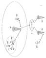
도 1은, 본 발명의 실시형태에 의한 통신 시스템(1)의 구성을 나타낸 설명도이다. 도 1에 도시한 바와 같이, 본 발명의 실시형태에 의한 통신 시스템(1)은, 복수의 기지국(10A, 10B 및 10C)과, 백본 네트워크(12)와, 복수의 이동 단말기(20A, 20B 및 20C)와, 복수의 중계 장치(30A 및 30B)를 구비한다.1 is an explanatory diagram showing a configuration of a
복수의 기지국(10A, 10B 및 10C)은, 각각의 전파 도달 범위 내에 존재하는 이동 단말기(20)와 통신하기 위한 스케줄 정보를 관리한다. 그리고, 복수의 기지국(10A, 10B 및 10C)은, 각각의 전파 도달 범위 내에 존재하는 이동 단말기(20)와, 상기 스케줄 정보에 따라 통신한다.The plurality of
예를 들어, 기지국(10A)은, 기지국(10A)의 전파 도달 범위 내에 존재하는 이동 단말기(20C)와 통신하기 위한 주파수-시간의 스케줄 정보를 관리한다. 그리고 기지국(10A)은, 기지국(10A)의 전파 도달 범위 내에 존재하는 이동 단말기(20C)와, 상기 스케줄 정보에 따라 통신한다.For example, the
또한, 복수의 기지국(10A, 10B 및 10C)은, 각각의 전파 도달 범위 내에 존재하는 중계 장치(30)를 통해 이동 단말기(20)와 통신하는 것도 가능하다. 이 경우, 복수의 기지국(10A, 10B 및 10C)은, 중계 장치(30)와 통신하기 위한 스케줄 정보 및 중계 장치(30)와 이동 단말기(20)가 통신하기 위한 스케줄 정보를 관리한다.In addition, the plurality of
예를 들어, 기지국(10A)은, 기지국(10A)의 전파 도달 범위 내에 존재하는 중계 장치(30A)와 통신하기 위한 주파수-시간의 스케줄 정보를 관리하고, 중계 장치(30A)와 이동 단말기(20A, 20B)가 통신하기 위한 주파수-시간의 스케줄 정보를 관리한다. 그리고 기지국(10A)은 중계 장치(30A)와, 상기 스케줄 정보에 따라 통신한다.For example, the
또한, 본 명세서에 있어서는, 주파수-시간의 스케줄 관리를 기지국(10)이 행하는 예에 중점을 두고 설명하지만, 본 발명이 이러한 예로 한정되지 않는다. 예를 들어, 주파수-시간의 스케줄 관리는, 기지국(10)과 중계 장치(30)가 협동하여 행해도 좋고, 기지국(10)과 중계 장치(30)와 이동 단말기(20)가 협동하여 행해도 좋고, 중계 장치(30)가 행해도 좋다.In addition, although description centering on the example which the
또한, 복수의 기지국(10A, 10B 및 10C)은, 백본 네트워크(12)를 통해 접속되어 있다. 복수의 기지국(10A, 10B 및 10C)은, 이 백본 네트워크(12)를 통해, 예를 들어 각각이 관리하는 스케줄 정보를 교환할 수 있다.In addition, the plurality of
중계 장치(30)는, 기지국(10)과 이동 단말기(20)와의 통신을, 기지국(10)이 관리하는 주파수-시간의 스케줄 정보에 따라 중계한다. 구체적으로는, 중계 장치(30)는, 다운 링크에 있어서, 기지국(10)으로부터 송신된 신호를 수신하여 증폭한 신호를, 스케줄 정보에 따른 주파수-시간을 이용해서 이동 단말기(20)에 송신한다. 중계 장치(30)는, 이러한 중계를 행함으로써, 기지국(10)으로부터 셀 엣지 부근의 이동 단말기(20)에 대하여 신호를 직접 송신하는 경우보다도, 신호 대 잡음비를 높게 하는 것이 가능하다.The
마찬가지로, 중계 장치(30)는 업 링크에 있어서도, 이동 단말기(20)로부터 송신된 신호를 기지국(10)이 관리하는 주파수-시간의 스케줄 정보에 따라서 기지국(10)에 중계함으로써, 신호 대 잡음비를 높게 유지할 수 있다. 또한, 도 1에 있어서는, 기지국(10A)이 제공하는 셀에 중계 장치(30A)만이 존재하는 예를 나타내고 있지만, 기지국(10A)이 제공하는 셀에 복수의 중계 장치(30)가 존재해도 좋다. 여기서 도 2를 참조하여 각 링크명을 정리한다.Similarly, the
도 2는, 본 발명의 실시형태에 의한 통신 시스템(1)에 있어서의 각 링크를 나타낸 설명도이다. 도 2에 도시한 바와 같이, 기지국(10)과 이동 단말기(20) 사이의 직접적인 통신 경로를 다이렉트 링크라 칭한다. 또한, 이 다이렉트 링크의 다운 링크를 다이렉트 다운 링크(D-d)라 칭하고, 다이렉트 링크의 업 링크를 다이렉트 업 링크(D-u)라 칭한다.2 is an explanatory diagram showing each link in the
또한, 기지국(10)과 중계 장치(30) 사이의 통신 경로를 릴레이 링크라 칭하고, 이 릴레이 링크의 다운 링크를 릴레이 다운 링크(R-d)라 칭하고, 릴레이 링크의 업 링크를 릴레이 업 링크(R-u)라 칭한다. 또한, 중계 장치(30)와 기지국(10) 사이의 통신 경로를 액세스 링크라 칭하고, 이 액세스 링크의 다운 링크를 액세스 다운 링크(A-d)라 칭하고, 액세스 링크의 업 링크를 액세스 업 링크(A-u)라 칭한다.In addition, the communication path between the
도 1을 참조하여, 통신 시스템(1)의 설명으로 되돌아간다. 통신 시스템(1)에 포함되는 이동 단말기(20)는, 상술한 바와 같이 기지국(10)과 직접 또는 중계 장치(30)를 통해 기지국(10)에 의해 관리되는 스케줄 정보에 따라 통신한다. 또한, 이동 단말기(20)가 송수신하는 데이터로는, 음성 데이터나, 음악, 강연 및 라디오 프로그램 등의 음악 데이터나, 사진, 문서, 회화, 도표 등의 정지 화상 데이터나, 영화, 텔레비전 프로그램, 비디오 프로그램, 게임 화상 등의 동화상 데이터 등을 들 수 있다.With reference to FIG. 1, the description returns to the description of the
여기서 도 3을 참조하여, 본 실시형태에 의한 통신 시스템(1)에서 이용되는 무선 프레임의 구성을 설명한다.Here, with reference to FIG. 3, the structure of the radio frame used by the
도 3은, 본 실시형태에 의한 통신 시스템(1)에서 이용되는 무선 프레임의 구성예를 나타낸 설명도이다. 도 3에 도시한 바와 같이, 각 무선 프레임(Radio Frame)의 길이는 10ms다. 또한, 각 무선 프레임은, 길이가 1ms인 10의 서브 프레임(Sub Frame) #0 내지 #9로 구성된다.3 is an explanatory diagram showing a configuration example of a radio frame used in the
또한, 각 서브 프레임은 2의 0.5ms 슬롯으로 구성되어 있으며, 각 0.5ms 슬롯은 7의 OFDM(orthogonal frequency division multiplexing) 심볼로 구성되어 있다.In addition, each subframe consists of two 0.5 ms slots, and each 0.5 ms slot consists of seven orthogonal frequency division multiplexing (OFDM) symbols.
또한, 서브 프레임 #0 및 #5에 포함되는 전반의 0.5ms 슬롯의 5번째 및 6번째의 OFDM 심볼은, 동기용 레퍼런스 신호의 송신에 이용된다. 이동 단말기(20)는, 기지국(10) 또는 중계국(30)으로부터 송신되는 이 레퍼런스 신호에 기초하여 셀 서치 및 동기 처리를 행한다.In addition, the fifth and sixth OFDM symbols of the first 0.5 ms slots included in
또한, 기지국(10)은, 이동 단말기(20)와의 통신을 위해 상기한 0.5ms 슬롯 단위로 시간을 할당한다. 또한, 업 링크와 다운 링크를 분리하기 위해, FDD(Frequency Division Duplex) 및 TDD(Time Division Duplex)가 이용된다. TDD의 경우에는, 1 서브 프레임마다 서브 프레임을 업 링크에 사용할 것인지, 다운 링크에 사용할 것인지를 선택하는 것이 가능하다.In addition, the
<2. 이동 단말기의 구성><2. Mobile Terminal Configuration>
이상, 도 1 내지 도 3을 참조하여, 본 실시형태에 의한 통신 시스템(1)에 대해서 개략적으로 설명하였다. 계속해서, 도 4를 참조하여, 본 실시형태에 의한 통신 시스템(1)에 포함되는 이동 단말기(20)의 구성을 설명한다.In the above, the
도 4는, 이동 단말기(20)의 구성을 도시한 기능 블록도이다. 도 4에 도시한 바와 같이, 이동 단말기(20)는, 복수의 안테나(220a 내지 220n)와, 아날로그 처리부(224)와, AD?DA 변환부(228)와, 디지털 처리부(230)를 구비한다.4 is a functional block diagram showing the configuration of the
복수의 안테나(220a 내지 220n)의 각각은, 기지국(10) 또는 중계 장치(30)로부터 무선 신호를 수신해서 전기적인 고주파 신호를 취득하고, 고주파 신호를 아날로그 처리부(224)에 공급한다. 또한, 복수의 안테나(220a 내지 220n)의 각각은, 아날로그 처리부(224)로부터 공급되는 고주파 신호에 기초하여 기지국(10) 또는 중계 장치(30)에 무선 신호를 송신한다. 이동 단말기(20)는, 이와 같이 복수의 안테나(220a 내지 220n)를 구비하기 때문에, MIMO(Multiple Input Multiple Output) 통신이나 다이버시티 통신을 행하는 것이 가능하다.Each of the plurality of
아날로그 처리부(224)는, 증폭, 필터링 및 다운 컨버전 등의 아날로그 처리를 행함으로써, 복수의 안테나(220a 내지 220n)로부터 공급되는 고주파 신호를 기저 대역 신호로 변환한다. 또한, 아날로그 처리부(224)는, AD?DA 변환부(228)로부터 공급되는 기저 대역 신호를 고주파 신호로 변환한다.The
AD?DA 변환부(228)는, 아날로그 처리부(224)로부터 공급되는 아날로그 형식의 기저 대역 신호를 디지털 형식으로 변환하고, 디지털 처리부(230)에 공급한다. 또한, AD?DA 변환부(228)는, 디지털 처리부(230)로부터 공급되는 디지털 형식의 기저 대역 신호를 아날로그 형식으로 변환하고, 아날로그 처리부(224)에 공급한다.The AD?
디지털 처리부(230)는, 동기부(232)와, 디코더(234)와, SINR(Signal to Interference plus Noise Ratio) 취득부(236)와, 송신 데이터 생성부(238)와, 인코더(240)와, 제어부(242)와, 스케줄 정보 유지부(244)를 구비한다. 이 중, 동기부(232), 디코더(234) 및 인코더(240) 등은, 복수의 안테나(220a 내지 220n), 아날로그 처리부(224) 및 AD?DA 변환부(228)와 함께, 기지국(10)이나 중계 장치(30)와 통신하기 위한 통신부로서 기능한다.The
동기부(232)는, 기지국(10)이나 중계 장치(30)로부터 송신된 레퍼런스 신호가 AD?DA 변환부(228)로부터 공급되고, 이 레퍼런스 신호에 기초하여 무선 프레임의 동기 처리를 행한다. 구체적으로는, 동기부(232)는, 레퍼런스 신호와 기지의 시퀀스 패턴과의 상관을 연산하여, 상관의 피크 위치를 검출함으로써 무선 프레임의 동기를 취한다.The
디코더(234)는, AD?DA 변환부(228)로부터 공급되는 기저 대역 신호를 디코드해서 수신 데이터를 얻는다. 또한, 상기 디코드는, 예를 들어 MIMO 수신 처리 및 OFDM 복조 처리를 포함하여도 된다.The
SINR 취득부(236)는, 동기부(232)에 의해 얻어진 레퍼런스 신호의 상관으로부터, 중계 장치(30) 사이의 SINR의 크기를 취득한다. 여기서, 각 중계 장치(30)는, 복수의 시퀀스 패턴 중 어느 하나를 갖는 레퍼런스 신호를 송신한다. 이로 인해, SINR 취득부(236)는, 레퍼런스 신호의 시퀀스 패턴의 차이에 기초하여 중계 장치(30)마다 SINR을 취득할 수 있다.The
송신 데이터 생성부(238)는, SINR 취득부(236)로부터 중계 장치(30)마다 SINR을 나타내는 정보가 공급되고, 이 정보를 포함하는 송신 데이터를 생성해서 인코더(240)에 공급한다.The transmission
인코더(240)는, 송신 데이터 생성부(238)로부터 공급되는 송신 데이터를 인코드하고, AD?DA 변환부(228)에 공급한다. 또한, 인코드는, 예를 들어 MIMO 송신 처리 및 OFDM 변조 처리를 포함하여도 된다.The
제어부(242)는, 이동 단말기(20)에 있어서의 송신 처리 및 수신 처리를, 스케줄 정보 유지부(244)에 유지되고 있는 스케줄 정보에 따라 제어한다. 예를 들어, 이동 단말기(20)는, 제어부(242)에 의한 제어에 기초하여, 스케줄 정보가 나타내는 주파수-시간 블록을 이용해서 송신 처리 및 수신 처리를 행한다.The
스케줄 정보 유지부(244)는, 기지국(10)에 의해 관리되는 스케줄 정보를 유지한다. 이 스케줄 정보는, 예를 들어 액세스 다운 링크에 이용하는 주파수-시간 블록, 액세스 업 링크에 이용하는 주파수-시간 블록을 나타낸다.The schedule
또한, 업 링크 및 다운 링크의 스케줄 정보는, 하향 링크 제어 채널인 PDCH(Physical Downlink Control Channel)에 포함된다. 또한, 이 PDCH는, 무선 프레임 중에서 다운 링크에 할당되는 서브 프레임의 선두인 1 내지 3O FDM 심볼을 이용해서 송신된다.In addition, uplink and downlink schedule information is included in a physical downlink control channel (PDCH) which is a downlink control channel. This PDCH is transmitted using 1 to 3 0 FDM symbols, which are the heads of subframes allocated to the downlink in the radio frame.
<3. 중계 장치의 구성><3. Relay Device Configuration>
이어서, 도 5를 참조하여, 중계 장치(30)의 구성을 설명한다.Next, with reference to FIG. 5, the structure of the
도 5는, 중계 장치(30)의 구성을 도시한 기능 블록도이다. 도 5에 도시한 바와 같이, 중계 장치(30)는 복수의 안테나(320a 내지 320n)와, 아날로그 처리부(324)와, AD?DA 변환부(328)와, 디지털 처리부(330)를 구비한다.5 is a functional block diagram showing the configuration of the
복수의 안테나(320a 내지 320n)의 각각은, 기지국(10) 또는 이동 단말기(20)로부터 무선 신호를 수신해서 전기적인 고주파 신호를 취득하고, 고주파 신호를 아날로그 처리부(324)에 공급한다. 또한, 복수의 안테나(320a 내지 320n)의 각각은, 아날로그 처리부(324)로부터 공급되는 고주파 신호에 기초하여 기지국(10) 또는 이동 단말기(20)에 무선 신호를 송신한다. 중계 장치(30)는, 이와 같이 복수의 안테나(320a 내지 320n)를 구비하기 때문에, MIMO 통신이나 다이버시티 통신을 행하는 것이 가능하다.Each of the plurality of
아날로그 처리부(324)는, 증폭, 필터링 및 다운 컨버전 등의 아날로그 처리를 행함으로써, 복수의 안테나(320a 내지 320n)로부터 공급되는 고주파 신호를 기저 대역 신호로 변환한다. 또한, 아날로그 처리부(324)는, AD?DA 변환부(328)로부터 공급되는 기저 대역 신호를 고주파 신호로 변환한다.The
AD?DA 변환부(328)는, 아날로그 처리부(324)로부터 공급되는 아날로그 형식의 기저 대역 신호를 디지털 형식으로 변환하고, 디지털 처리부(330)에 공급한다. 또한, AD?DA 변환부(328)는, 디지털 처리부(330)로부터 공급되는 디지털 형식의 기저 대역 신호를 아날로그 형식으로 변환하고, 아날로그 처리부(324)에 공급한다.The AD?
디지털 처리부(330)는, 동기부(332)와, 디코더(334)와, 버퍼(338)와, 인코더(340)와, 제어부(342)와, 스케줄 정보 유지부(344)를 구비한다. 이 중, 동기부(332), 디코더(334) 및 인코더(340) 등은, 복수의 안테나(320a 내지 320n), 아날로그 처리부(324) 및 AD?DA 변환부(328)와 함께, 기지국(10)이나 이동 단말기(20)와 통신하기 위한 통신부로서 기능한다.The
동기부(332)는, 기지국(10)으로부터 송신된 레퍼런스 신호가 AD?DA 변환부(328)로부터 공급되고, 이 레퍼런스 신호에 기초하여 무선 프레임의 동기 처리를 행한다. 구체적으로는, 동기부(332)는, 레퍼런스 신호와 기지의 시퀀스 패턴과의 상관을 연산하여, 상관의 피크 위치를 검출함으로써 무선 프레임의 동기를 취한다.The
디코더(334)는, AD?DA 변환부(328)로부터 공급되는 기저 대역 신호를 디코드해서 기지국(10)당 또는 이동 단말기(20)당 중계 데이터를 얻는다. 또한, 디코드는, 예를 들어 MIMO 수신 처리, OFDM 복조 처리 및 오류 정정 처리 등을 포함하여도 된다.The
버퍼(338)는, 디코더(334)에 의해 얻어진 기지국(10)당 또는 이동 단말기(20)당 중계 데이터를 일시적으로 유지한다. 그리고, 제어부(342)의 제어에 의해, 이동 단말기(20)에의 액세스 다운 링크의 송신 시간에 있어서 버퍼(338)로부터 인코더(340)에 이동 단말기(20)당 중계 데이터가 판독된다. 마찬가지로, 제어부(342)의 제어에 의해, 기지국(10)에의 릴레이 업 링크의 송신 시간에 있어서 버퍼(338)로부터 인코더(340)에 기지국(10)당 중계 데이터가 판독된다.The
인코더(340)는, 버퍼(338)로부터 공급되는 데이터를 인코드하고, AD?DA 변환부(328)에 공급한다. 또한, 인코드는, 예를 들어 MIMO 송신 처리 및 OFDM 변조 처리를 포함하여도 된다.The
제어부(342)는, 중계 장치(30)에 있어서의 송신 처리 및 수신 처리를, 스케줄 정보 유지부(344)에 유지되어 있는 스케줄 정보에 따라 제어한다. 예를 들어, 중계 장치(30)는, 제어부(342)에 의한 제어에 기초하여, 스케줄 정보가 나타내는 주파수-시간 블록을 이용해서 송신 처리 및 수신 처리를 행한다.The
스케줄 정보 유지부(344)는, 기지국(10)에 의해 관리되는 스케줄 정보를 유지한다. 이 스케줄 정보는, 예를 들어 릴레이 다운 링크, 액세스 다운 링크, 액세스 업 링크 및 릴레이 업 링크의 각각에 이용하는 주파수-시간 블록을 나타낸다.The schedule
<4. 기지국의 구성><4. Base station configuration>
계속해서, 도 6 내지 도 16을 참조하여, 기지국(10)의 구성을 설명한다.6-16, the structure of the
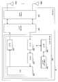
도 6은, 기지국(10)의 구성을 도시한 기능 블록도이다. 도 6에 도시한 바와 같이, 기지국(10)은 복수의 안테나(120a 내지 120n)와, 아날로그 처리부(124)와, AD?DA 변환부(128)와, 디지털 처리부(130)를 구비한다.6 is a functional block diagram showing the configuration of the
복수의 안테나(120a 내지 120n)의 각각은, 중계 장치(30) 또는 이동 단말기(20)로부터 무선 신호를 수신해서 전기적인 고주파 신호를 취득하고, 고주파 신호를 아날로그 처리부(124)에 공급한다. 또한, 복수의 안테나(120a 내지 120n)의 각각은, 아날로그 처리부(124)로부터 공급되는 고주파 신호에 기초하여 무선 신호를 중계 장치(30) 또는 이동 단말기(20)에 송신한다. 기지국(10)은, 이와 같이 복수의 안테나(120a 내지 120n)를 구비하기 때문에, MIMO 통신이나 다이버시티 통신을 행하는 것이 가능하다.Each of the plurality of
아날로그 처리부(124)는, 증폭, 필터링 및 다운 컨버전 등의 아날로그 처리를 행함으로써, 복수의 안테나(120a 내지 120n)로부터 공급되는 고주파 신호를 기저 대역 신호로 변환한다. 또한, 아날로그 처리부(124)는, AD?DA 변환부(128)로부터 공급되는 기저 대역 신호를 고주파 신호로 변환한다.The
AD?DA 변환부(128)는, 아날로그 처리부(124)로부터 공급되는 아날로그 형식의 기저 대역 신호를 디지털 형식으로 변환하고, 디지털 처리부(130)에 공급한다. 또한, AD?DA 변환부(128)는, 디지털 처리부(130)로부터 공급되는 디지털 형식의 기저 대역 신호를 아날로그 형식으로 변환하고, 아날로그 처리부(124)에 공급한다.The AD?
디지털 처리부(130)는, 디코더(134)와, 송신 데이터 생성부(138)와, 인코더(140)와, 제어부(142)와, 스케줄 정보 유지부(144)와, SINR 유지부(152)와, 중계 장치 정보 유지부(154)와, 스케줄러(156)를 구비한다. 이 중, 디코더(134) 및 인코더(140) 등은, 복수의 안테나(120a 내지 120n), 아날로그 처리부(124) 및 AD?DA 변환부(128)와 함께, 중계 장치(30)나 이동 단말기(20)와 통신하기 위한 통신부로서 기능한다.The
디코더(134)는, AD?DA 변환부(128)로부터 공급되는 기저 대역 신호를 디코드해서 수신 데이터를 얻는다. 또한, 디코드는, 예를 들어 MIMO 수신 처리, OFDM 복조 처리 및 오류 정정 처리 등을 포함하여도 된다.The
송신 데이터 생성부(138)는, 스케줄러(156)에 의해 스케줄 된 스케줄 정보를 포함하는 송신 데이터를 생성한다. 또한, 스케줄 정보는, 상술한 바와 같이 서브 프레임 선두에 배치되는 PDCH에 포함된다.The transmission
인코더(140)는, 송신 데이터 생성부(138)로부터 공급되는 송신 데이터를 인코드하고, AD?DA 변환부(128)에 공급한다. 또한, 인코드는, 예를 들어 MIMO 송신 처리 및 OFDM 변조 처리를 포함하여도 된다.The
제어부(142)는, 기지국(10)에 있어서의 송신 처리 및 수신 처리를, 스케줄 정보 유지부(144)에 유지되어 있는 스케줄 정보에 따라 제어한다. 예를 들어, 기지국(10)은, 제어부(142)에 의한 제어에 기초하여, 스케줄 정보가 나타내는 주파수-시간 블록을 이용해서 송신 처리 및 수신 처리를 행한다.The
스케줄 정보 유지부(144)는, 스케줄러(156)에 의해 결정된 스케줄 정보를 유지한다.The schedule
스케줄러(156)(선택부)는, 중계 장치(30)와의 릴레이 링크 통신 및 중계 장치(30)와 이동 단말기(20)와의 액세스 링크 통신을 스케줄한다. 여기서, 스케줄러(156)는, 릴레이 다운 링크, 액세스 다운 링크, 액세스 업 링크 및 릴레이 업 링크를 위한 리소스를, 간섭 회피의 관점에서 주파수?시간으로 분리한다. 이하, 도 7 내지 도 14를 참조하여, 리소스를 주파수?시간으로 분리 가능한 할당 패턴을 설명한다.The scheduler 156 (selector) schedules relay link communication with the
(할당 패턴 1)(Assignment pattern 1)
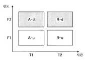
도 7은, 각 링크의 할당 패턴 1을 나타낸 설명도이다. 도 7에 도시한 바와 같이, 할당 패턴 1에 있어서는, 주파수 F2?슬롯 T1로 정의되는 주파수-시간 블록에 릴레이 다운 링크(R-d)가 할당되고, 주파수 F2?슬롯 T2로 정의되는 주파수-시간 블록에 액세스 다운 링크(A-d)가 할당되고, 주파수 F1?슬롯 T1로 정의되는 주파수-시간 블록에 액세스 업 링크(A-u)가 할당되고, 주파수 F1?슬롯 T2로 정의되는 주파수-시간 블록에 릴레이 업 링크(R-u)가 할당된다. 또한, 도 7 내지 도 16에 있어서는, 다운 링크가 할당되는 주파수-시간 블록에 색을 부가함으로써, 업 링크가 할당되는 주파수-시간 블록과 구별하고 있다. 또한, 주파수-시간 블록은, 링크 할당의 최소 단위인 리소스 블록이어도, 리소스 블록의 그룹이어도 좋다.7 is an explanatory diagram showing an
이 할당 패턴 1에 있어서는, 기지국(10)은, 주파수 F2?슬롯 T1로 릴레이 다운 링크를 통해 중계 장치(30)에 데이터를 송신한다. 그리고, 중계 장치(30)는, 릴레이 다운 링크를 통해 송신된 데이터를 수신하고, 버퍼(338)에 중계 데이터로서 유지시킨 후에, 주파수 F2?슬롯 T2로 액세스 다운 링크를 통해 이동 단말기(20)에 중계 데이터를 송신한다.In this
또한, 이동 단말기(20)는, 주파수 F1?슬롯 T1로 액세스 업 링크를 통해 중계 장치(30)에 데이터를 송신한다. 그리고, 중계 장치(30)는, 액세스 업 링크를 통해 송신된 데이터를 수신하고, 버퍼(338)에 중계 데이터로서 유지한 후에, 주파수 F1?슬롯 T2로 릴레이 업 링크를 통해 기지국(10)에 중계 데이터를 송신한다.The
이와 같이, 할당 패턴 1에 있어서는, 업 링크와 다운 링크가 주파수로 분리되고, 동일한 방향의 릴레이 링크와 액세스 링크가 시간으로 분리되기 때문에, 각 링크간의 간섭을 억제할 수 있다.Thus, in the
(할당 패턴 2)(Assignment pattern 2)
도 8은, 각 링크의 할당 패턴 2를 나타낸 설명도이다. 도 8에 도시한 바와 같이, 할당 패턴 2에 있어서는, 주파수 F2?슬롯 T1로 정의되는 주파수-시간 블록에 액세스 다운 링크(A-d)가 할당되고, 주파수 F2?슬롯 T2로 정의되는 주파수-시간 블록에 릴레이 다운 링크(R-d)가 할당되고, 주파수 F1?슬롯 T1로 정의되는 주파수-시간 블록에 액세스 업 링크(A-u)가 할당되고, 주파수 F1?슬롯 T2로 정의되는 주파수-시간 블록에 릴레이 업 링크(R-u)가 할당된다.8 is an explanatory diagram showing an
이 할당 패턴 2에 있어서는, 중계 장치(30)는, 버퍼(338)에 유지되어 있는 중계 데이터를, 주파수 F2?슬롯 T1로 액세스 다운 링크를 통해 이동 단말기(20)에 송신한다. 또한, 기지국(10)은, 주파수 F2?슬롯 T1로 릴레이 다운 링크를 통해 중계 장치(30)에 데이터를 송신한다.In this
또한, 이동 단말기(20)는, 주파수 F1?슬롯 T1로 액세스 업 링크를 통해 중계 장치(30)에 데이터를 송신한다. 그리고, 중계 장치(30)는, 액세스 업 링크를 통해 송신된 데이터를 수신하고, 버퍼(338)에 중계 데이터로서 유지한 후에, 주파수 F1?슬롯 T2로 릴레이 업 링크를 통해 기지국(10)에 중계 데이터를 송신한다.The
이와 같이, 할당 패턴 2에 있어서도, 업 링크와 다운 링크가 주파수로 분리되고, 동일한 방향의 릴레이 링크와 액세스 링크가 시간으로 분리되기 때문에, 각 링크간의 간섭을 억제할 수 있다.Thus, also in the
(할당 패턴 3)(Assignment pattern 3)
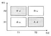
도 9는, 각 링크의 할당 패턴 3을 나타낸 설명도이다. 도 9에 도시한 바와 같이, 할당 패턴 3에 있어서는, 주파수 F2?슬롯 T1로 정의되는 주파수-시간 블록에 릴레이 다운 링크(R-d)가 할당되고, 주파수 F1?슬롯 T2로 정의되는 주파수-시간 블록에 액세스 다운 링크(A-d)가 할당되고, 주파수 F1?슬롯 T1로 정의되는 주파수-시간 블록에 액세스 업 링크(A-u)가 할당되고, 주파수 F2?슬롯 T2로 정의되는 주파수-시간 블록에 릴레이 업 링크(R-u)가 할당된다.9 is an explanatory diagram showing an
이 할당 패턴 3에 있어서는, 기지국(10)은, 주파수 F2?슬롯 T1로 릴레이 다운 링크를 통해 중계 장치(30)에 데이터를 송신한다. 그리고, 중계 장치(30)는, 릴레이 다운 링크를 통해 송신된 데이터를 수신하고, 버퍼(338)에 중계 데이터로서 유지한 후에, 주파수 F1?슬롯 T2로 액세스 다운 링크를 통해 이동 단말기(20)에 중계 데이터를 송신한다.In this
또한, 이동 단말기(20)는, 주파수 F1?슬롯 T1로 액세스 업 링크를 통해 중계 장치(30)에 데이터를 송신한다. 그리고, 중계 장치(30)는, 액세스 업 링크를 통해 송신된 데이터를 수신하고, 버퍼(338)에 중계 데이터로서 유지한 후에, 주파수 F2?슬롯 T2로 릴레이 업 링크를 통해 기지국(10)에 중계 데이터를 송신한다.The
이와 같이, 할당 패턴 3에 있어서는, 업 링크와 다운 링크가 주파수로 분리되고, 동일한 방향의 릴레이 링크와 액세스 링크는 주파수 및 시간으로 분리되기 때문에, 각 링크간의 간섭을 억제할 수 있다.Thus, in the
(할당 패턴 4)(Assignment pattern 4)
도 10은, 각 링크의 할당 패턴 4를 나타낸 설명도이다. 도 10에 도시한 바와 같이, 할당 패턴 4에 있어서는, 주파수 F2?슬롯 T1로 정의되는 주파수-시간 블록에 릴레이 다운 링크(R-d)가 할당되고, 주파수 F1-슬롯 T2로 정의되는 주파수-시간 블록에 액세스 다운 링크(A-d)가 할당되고, 주파수 F2-슬롯 T2로 정의되는 주파수-시간 블록에 액세스 업 링크(A-u)가 할당되고, 주파수 F1-슬롯 T1로 정의되는 주파수-시간 블록에 릴레이 업 링크(R-u)가 할당된다.10 is an explanatory diagram showing an
이 할당 패턴 4에 있어서는, 기지국(10)은, 주파수 F2-슬롯 T1로 릴레이 다운 링크를 통해 중계 장치(30)에 데이터를 송신한다. 그리고, 중계 장치(30)는, 릴레이 다운 링크를 통해 송신된 데이터를 수신하고, 버퍼(338)에 중계 데이터로서 유지한 후에, 주파수 F1-슬롯 T2로 액세스 다운 링크를 통해 이동 단말기(20)에 중계 데이터를 송신한다.In this
또한, 중계 장치(30)는, 버퍼(338)에 유지되어 있는 중계 데이터를, 주파수 F1-슬롯 T1로 릴레이 업 링크를 통해 기지국(10)에 송신한다. 또한, 이동 단말기(20)는, 주파수 F2-슬롯 T2로 액세스 업 링크를 통해 중계 장치(30)에 데이터를 송신한다.The
이와 같이, 할당 패턴 4에 있어서도, 업 링크와 다운 링크가 주파수로 분리되고, 동일한 방향의 릴레이 링크와 액세스 링크는 주파수 및 시간으로 분리되기 때문에, 각 링크간의 간섭을 억제할 수 있다.In this manner, also in the
(할당 패턴 5)(Assignment pattern 5)
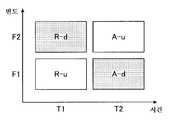
도 11은, 각 링크의 할당 패턴 5를 나타낸 설명도이다. 도 11에 도시한 바와 같이, 할당 패턴 5에 있어서는, 주파수 F1-슬롯 T1로 정의되는 주파수-시간 블록에 릴레이 다운 링크(R-d)가 할당되고, 주파수 F2-슬롯 T1로 정의되는 주파수-시간 블록에 액세스 다운 링크(A-d)가 할당되고, 주파수 F1-슬롯 T2로 정의되는 주파수-시간 블록에 액세스 업 링크(A-u)가 할당되고, 주파수 F2-슬롯 T2로 정의되는 주파수-시간 블록에 릴레이 업 링크(R-u)가 할당된다.11 is an explanatory diagram showing an
상술한 바와 같이 할당 패턴 5에 있어서는, 할당 패턴 1 내지 4와 상이하고, 릴레이 링크와 액세스 링크가 주파수로 분리되어 있다. 이로 인해, 릴레이 링크의 다운 링크 및 액세스 링크의 다운 링크간에서 발생하는 지연을, 슬롯 단위가 아닌, OFDM 심볼 단위로 단축할 수 있다. 마찬가지로, 액세스 링크의 업 링크 및 릴레이 링크의 업 링크간에서 발생하는 지연을, 슬롯 단위가 아닌, OFDM 심볼 단위로 단축할 수 있다.As described above, in the
구체적으로는, 기지국(10)은, 주파수 F1-슬롯 T1로 릴레이 다운 링크를 통해 중계 장치(30)에 데이터를 송신한다. 그리고, 중계 장치(30)는, 릴레이 다운 링크를 통해 수신한 데이터의 디코드, 버퍼링, 인코드 및 액세스 다운 링크를 통한 이동 단말기(20)에의 송신을, 수신으로부터 OFDM 심볼 단위의 지연량에서, 주파수 F2-슬롯 T1을 이용해서 행한다. 또한, 지연량은 1OFDM 심볼 내지 복수의 OFDM 심볼 사이에서 가변이어도 좋다.Specifically, the
또한, 이동 단말기(20)는, 주파수 F1-슬롯 T2로 액세스 업 링크를 통해 중계 장치(30)에 데이터를 송신한다. 그리고, 중계 장치(30)는, 액세스 업 링크를 통해 수신한 데이터의 디코드, 버퍼링, 인코드 및 릴레이 업 링크를 통한 기지국(10)에의 송신을, 수신으로부터 OFDM 심볼 단위의 지연량으로, 주파수 F2-슬롯 T2를 이용해서 행한다.The
이와 같이, 할당 패턴 5에 있어서는, 릴레이 링크와 액세스 링크가 주파수에서 분리되고(FDD), 업 링크와 다운 링크가 시간으로 분리된다(TDD). 이로 인해, 할당 패턴 5에 의하면, 각 링크간의 간섭을 억제하면서, 기지국(10) 및 이동 단말기(20) 사이에서 발생하는 지연을, 릴레이 링크와 액세스 링크를 시간으로 분리하는 할당 패턴 1 내지 4보다 단축할 수 있다.Thus, in the
(할당 패턴 6)(Assignment pattern 6)
도 12는, 각 링크의 할당 패턴 6을 나타낸 설명도이다. 도 12에 도시한 바와 같이, 할당 패턴 6에 있어서는, 주파수 F1-슬롯 T1로 정의되는 주파수-시간 블록에 릴레이 다운 링크(R-d)가 할당되고, 주파수 F2-슬롯 T1로 정의되는 주파수-시간 블록에 액세스 다운 링크(A-d)가 할당되고, 주파수 F2-슬롯 T2로 정의되는 주파수-시간 블록에 액세스 업 링크(A-u)가 할당되고, 주파수 F1-슬롯 T2로 정의되는 주파수-시간 블록에 릴레이 업 링크(R-u)가 할당된다.12 is an explanatory diagram showing an
이와 같이, 할당 패턴 6에 있어서도, 할당 패턴 5와 마찬가지로, 릴레이 링크와 액세스 링크가 주파수로 분리되어 있다. 이로 인해, 릴레이 링크의 다운 링크 및 액세스 링크의 다운 링크 사이에서 발생하는 지연을, 슬롯 단위가 아닌, OFDM 심볼 단위로 단축할 수 있다. 마찬가지로, 액세스 링크의 업 링크 및 릴레이 링크의 업 링크간에서 발생하는 지연을, 슬롯 단위가 아닌, OFDM 심볼 단위로 단축할 수 있다.In this manner, also in the
구체적으로는, 기지국(10)은, 주파수 F1-슬롯 T1로 릴레이 다운 링크를 통해 중계 장치(30)에 데이터를 송신한다. 그리고, 중계 장치(30)는, 릴레이 다운 링크를 통해 수신한 데이터의 디코드, 버퍼링, 인코드 및 액세스 다운 링크를 통한 이동 단말기(20)에의 송신을, 수신으로부터 OFDM 심볼 단위의 지연량에서, 주파수 F2-슬롯 T1을 이용해서 행한다. 또한, 지연량은 1OFDM 심볼 내지 복수의 OFDM 심볼 사이에서 가변이어도 좋다.Specifically, the
또한, 이동 단말기(20)는, 주파수 F2-슬롯 T2로 액세스 업 링크를 통해 중계 장치(30)에 데이터를 송신한다. 그리고, 중계 장치(30)는, 액세스 업 링크를 통해 수신한 데이터의 디코드, 버퍼링, 인코드 및 릴레이 업 링크를 통한 기지국(10)에의 송신을, 수신으로부터 OFDM 심볼 단위의 지연량으로, 주파수 F1-슬롯 T2를 이용해서 행한다.The
이와 같이, 할당 패턴 6에 있어서는, 릴레이 링크와 액세스 링크가 주파수로 분리되고(FDD), 업 링크와 다운 링크가 시간 및 주파수로 분리된다(TDD). 이로 인해, 할당 패턴 6에 의하면, 각 링크간의 간섭을 억제하면서, 기지국(10) 및 이동 단말기(20) 사이에서 발생하는 지연을, 릴레이 링크와 액세스 링크를 시간으로 분리하는 할당 패턴 1 내지 4보다 단축할 수 있다.Thus, in the
(할당 패턴 7)(Assignment pattern 7)
도 13은, 각 링크의 할당 패턴 7을 나타낸 설명도이다. 도 13에 도시한 바와 같이, 할당 패턴 7에 있어서는, 주파수 F1-슬롯 T1로 정의되는 주파수-시간 블록에 릴레이 다운 링크(R-d)가 할당되고, 주파수 F2-슬롯 T1로 정의되는 주파수-시간 블록에 액세스 다운 링크(A-d)가 할당되고, 주파수 F3-슬롯 T1로 정의되는 주파수-시간 블록에 액세스 업 링크(A-u)가 할당되고, 주파수 F4-슬롯 T1로 정의되는 주파수-시간 블록에 릴레이 업 링크(R-u)가 할당된다.13 is an explanatory diagram showing an
이와 같이, 할당 패턴 7에 있어서는, 릴레이 링크와 액세스 링크가 주파수로 분리되며, 업 링크와 다운 링크도 주파수로 분리되어 있다. 이로 인해, 할당 패턴 7에 의하면, 할당 패턴 5 및 6과 마찬가지로, 중계 장치(30)에 있어서의 지연을 OFDM 심볼 단위로 단축할 수 있으며, 업 링크 또는 다운 링크 중 하나를 이용하기 위해서, 다른 것의 종료를 기다리지 않아도 된다.Thus, in the
구체적으로는, 기지국(10)은, 주파수 F1-슬롯 T1로 릴레이 다운 링크를 통해 중계 장치(30)에 데이터를 송신한다. 그리고, 중계 장치(30)는, 릴레이 다운 링크를 통해 수신한 데이터의 디코드, 버퍼링, 인코드 및 액세스 다운 링크를 통한 이동 단말기(20)에의 송신을, 수신으로부터 OFDM 심볼 단위의 지연량으로, 주파수 F2-슬롯 T1을 이용해서 행한다. 또한, 지연량은 1OFDM 심볼 내지 복수의 OFDM 심볼 사이에서 가변이어도 좋다.Specifically, the
또한, 이동 단말기(20)는, 주파수 F3-슬롯 T1로 액세스 업 링크를 통해 중계 장치(30)에 데이터를 송신한다. 그리고, 중계 장치(30)는, 액세스 업 링크를 통해 수신한 데이터의 디코드, 버퍼링, 인코드 및 릴레이 업 링크를 통한 기지국(10)에의 송신을, 수신으로부터 OFDM 심볼 단위의 지연량으로, 주파수 F4-슬롯 T1을 이용해서 행한다.The
(할당 패턴 8)(Assignment pattern 8)
도 14는, 각 링크의 할당 패턴 8을 나타낸 설명도이다. 도 14에 도시한 바와 같이, 할당 패턴 8에 있어서는, 주파수 F1-슬롯 T1로 정의되는 주파수-시간 블록에 릴레이 다운 링크(R-d)가 할당되고, 주파수 F1-슬롯 T2로 정의되는 주파수-시간 블록에 액세스 다운 링크(A-d)가 할당되고, 주파수 F1-슬롯 T3로 정의되는 주파수-시간 블록에 액세스 업 링크(A-u)가 할당되고, 주파수 F1-슬롯 T4로 정의되는 주파수-시간 블록에 릴레이 업 링크(R-u)가 할당된다.14 is an explanatory diagram showing an
이와 같이, 할당 패턴 8에 있어서는, 릴레이 링크와 액세스 링크가 시간으로 분리되며, 업 링크와 다운 링크도 시간으로 분리되어 있다. 이로 인해, 할당 패턴 8에 의하면, 이용하는 주파수는 적지만, 다른 할당 패턴에 비하여 지연 특성이 열화된다.Thus, in the
구체적으로는, 할당 패턴 1에 있어서는, 기지국(10)은, 주파수 F1-슬롯 T1로 릴레이 다운 링크를 통해 중계 장치(30)에 데이터를 송신한다. 그리고, 중계 장치(30)는, 릴레이 다운 링크를 통해 송신된 데이터를 수신하고, 버퍼(338)에 중계 데이터로서 유지한 후에, 주파수 F1-슬롯 T2로 액세스 다운 링크를 통해 이동 단말기(20)에 중계 데이터를 송신한다.Specifically, in the
또한, 이동 단말기(20)는, 주파수 F1-슬롯 T3로 액세스 업 링크를 통해 중계 장치(30)에 데이터를 송신한다. 그리고, 중계 장치(30)는, 액세스 업 링크를 통해 송신된 데이터를 수신하고, 버퍼(338)에 중계 데이터로서 유지한 후에, 주파수 F1-슬롯 T4로 릴레이 업 링크를 통해 기지국(10)에 중계 데이터를 송신한다.The
(할당 패턴의 비교)(Comparison of Assignment Patterns)
상기한 바와 같이 복수의 링크 할당 패턴이 존재한다. 또한, 복수의 링크 할당 패턴은, 이하의 4가지 타입으로 분류된다.As described above, there are a plurality of link assignment patterns. In addition, the plurality of link assignment patterns are classified into the following four types.
?타입 AType A
업 링크와 다운 링크를 주파수로 분리하고, 동일한 방향의 릴레이 링크와 액세스 링크를 시간으로 분리하는 타입. 할당 패턴 1 내지 4가 타입 A에 해당한다.Type that separates uplink and downlink by frequency, and separates relay link and access link in the same direction by time.
?타입 BType B
업 링크와 다운 링크를 시간으로 분리하고, 동일한 방향의 릴레이 링크와 액세스 링크를 주파수로 분리하는 타입. 할당 패턴 5 및 6이 타입 B에 해당한다.Type that separates uplink and downlink by time, and separates relay link and access link by frequency in the same direction.
?타입 CType C
업 링크와 다운 링크 및 릴레이 링크와 액세스 링크를 주파수만으로 분리하는 타입. 할당 패턴 7이 타입 C에 해당한다.Type that separates uplink and downlink and relay link and access link by frequency only.
?타입 DType D
업 링크와 다운 링크 및 릴레이 링크와 액세스 링크를 시간만으로 분리하는 타입. 할당 패턴 8이 타입 C에 해당한다.Type that separates uplink and downlink and relay link and access link by time only.
상기한 타입 A 내지 타입 D의 각각에 속하는 할당 패턴은, (할당 패턴 1) 내지 (할당 패턴 8)에서 설명한 바와 같이 지연 특성이 상이하다. 구체적으로는, 타입 C가 가장 지연 특성이 양호하며, 타입 B, 타입 A, 타입 D의 순서로 지연 특성이 열화된다. 반대로, 이용하는 주파수 대역은, 타입 D가 가장 좁고, 타입 A, 타입 B, 타입 C의 순서로 넓어진다.The allocation patterns belonging to each of the above types A to D have different delay characteristics as described in (Assignment Pattern 1) to (Assignment Pattern 8). Specifically, Type C has the best delay characteristic, and the delay characteristic deteriorates in the order of Type B, Type A, and Type D. On the contrary, the frequency band to be used is the narrowest in type D and widens in the order of type A, type B and type C.
또한, 할당 패턴에 의해, 중계 장치(30)가 필요로 하는 통신 능력이 상이하다. 예를 들어, 할당 패턴 1을 따라 동작하기 위해서는, 중계 장치(30)는, 액세스 링크 및 릴레이 링크의 수신을 동시에 행하고, 액세스 링크 및 릴레이 링크의 송신을 동시에 행하는 통신 능력이 필요하다. 또한, 할당 패턴 7을 따라 동작하기 위해서는, 중계 장치(30)는 액세스 링크 및 릴레이 링크의 송수신을 동시에 행하는 통신 능력이 필요하다.Moreover, the communication capability which the
(스케줄러에 의한 스케줄링)(Scheduling by scheduler)
이상 설명한 바와 같이, 복수의 주파수-시간의 할당 패턴이 존재한다. 또한, 할당 패턴에 의해 지연 특성이나, 중계 장치(30)가 필요로 하는 통신 특성이 상이하다. 이로 인해, 스케줄러(156)는, 스케줄링 대상의 중계 장치(30)의 통신 능력이나, 이동 단말기(20) 사이에서 요구되는 지연 특성에 따라 적절한 스케줄링을 행한다. 이하, 스케줄러(156)에 의한 스케줄링에 대해서, SINR 유지부(152) 및 중계 장치 정보 유지부(154)의 구성에 맞춰서 설명한다.As described above, there are a plurality of frequency-time allocation patterns. Moreover, the delay characteristics and the communication characteristics required by the
SINR 유지부(152)는, 이동 단말기(20)로부터 통지되는 중계 장치(30)마다 SINR을 유지한다.The
중계 장치 정보 유지부(154)는, 중계 장치(30)로부터 통지되는 중계 장치(30)의 통신 능력을 나타내는 카테고리 정보를 유지한다. 예를 들어, 카테고리 1은, 할당 패턴 1에 따라서만 동작하는 통신 능력을 갖는 것을 나타내고, 카테고리 2는, 모든 할당 패턴 1 내지 8에 따라서 동작하는 통신 능력을 갖는 것을 나타낸다.The relay device
스케줄러(156)는, SINR 유지부(152)에 유지되는 중계 장치(30)마다의 SINR, 중계 장치 정보 유지부(154)에 유지되는 중계 장치(30)마다의 카테고리 정보 및 이동 단말기(20) 사이에서 요구되는 지연 특성에 따라 스케줄링을 행한다. 구체적인 스케줄링의 순서예를 이하에 나타낸다.The
(1) 스케줄러(156)는, SINR 유지부(152)에 유지되는 중계 장치(30)마다의 SINR로부터, 가장 SINR이 높은 중계 장치(30)를, 이동 단말기(20)와의 통신의 중계 장치로서 선택한다.(1) The
(2) 스케줄러(156)는, 중계 장치 정보 유지부(154)를 참조하여, 선택한 중계 장치(30)의 카테고리 정보를 얻는다.(2) The
(3) 스케줄러(156)는, 카테고리 정보가 나타내는 대응 가능한 할당 패턴 중에서, 이동 단말기(20) 사이에서 요구되는 지연 특성을 만족하는 할당 패턴을 선택한다.(3) The
(4) 스케줄러(156)는, 선택한 할당 패턴에 따라, 릴레이 다운 링크, 액세스 다운 링크, 액세스 업 링크 및 릴레이 업 링크를 각각 무선 프레임의 빈 주파수-시간 블록에 할당한다.(4) The
또한, 릴레이 다운 링크, 액세스 다운 링크, 액세스 업 링크 및 릴레이 업 링크를 각각 할당한 주파수-시간 블록을 나타내는 스케줄 정보는, 스케줄 정보 유지부(144)에 유지된다. 또한, 이 스케줄 정보는, 상기 (1)에서 선택된 중계 장치(30) 및 이동 단말기(20)에 송신된다. 그 결과, 중계 장치(30) 및 이동 단말기(20)는, 이 스케줄 정보에 따라 통신하는 것이 가능해진다.In addition, schedule information indicating the frequency-time block to which the relay down link, the access down link, the access up link, and the relay up link are respectively allocated is held in the schedule
또한, 스케줄러(156)는, 상기 (3)에 있어서, 이동 단말기(20) 사이에서 요구되는 지연 특성을, 예를 들어 전송 데이터의 속성에 따라 판단해도 좋다. 예를 들어, 스케줄러(156)는 전송 데이터가 리얼타임의 대전형 게임의 데이터일 경우, 최저 수준의 지연량이 요구되고 있다고 판단하여, 지연 특성이 가장 양호한 할당 패턴 7을 선택해도 좋다. 마찬가지로, 스케줄러(156)는, 전송 데이터가 음성 데이터, 정지 화상 데이터, 영상 데이터, 스트리밍 데이터 및 다운로드 데이터 등 중 어디에 해당하는지에 따라, 이동 단말기(20) 사이에서 요구되는 지연 특성을 판단해도 좋다.In addition, in the above (3), the
여기서, 도 15를 참조하여, 각 주파수-시간 블록에 할당되는 링크의 구체예를 설명한다.15, a specific example of a link allocated to each frequency-time block will be described.
도 15는, 무선 프레임을 구성하는 각 주파수-시간 블록에의 링크 할당예를 나타낸 설명도이다. 도 15에 도시한 예에서는, 서브 프레임 #0의 각 주파수-시간 블록에의 링크 할당이 할당 패턴 7에 따라서 행해지고, 서브 프레임 #1 및 #2의 각 주파수-시간 블록에의 링크 할당이 할당 패턴 2 및 할당 패턴 5에 따라서 행해지고 있다. 마찬가지로, 다른 서브 프레임의 주파수-시간 블록에도 어느 하나의 할당 패턴에 따라서 링크되어 있다.15 is an explanatory diagram showing an example of link assignment to each frequency-time block constituting a radio frame. In the example shown in FIG. 15, link allocation to each frequency-time block in
이와 같이, 본 실시형태에 따르면, 무선 프레임에서 다른 할당 패턴을 조합해서 통신을 행하는 것이 가능하다. 또한, 도 15에 있어서는, 서브 프레임이 주파수-시간 블록의 할당 단위인 예를 나타냈지만, 0.5ms 슬롯이 주파수-시간 블록의 할당 단위여도 좋다.As described above, according to the present embodiment, it is possible to perform communication by combining different allocation patterns in the radio frame. In FIG. 15, the subframe is an allocation unit of the frequency-time block. However, the 0.5 ms slot may be the allocation unit of the frequency-time block.
또한, 스케줄러(156)는, 각 주파수-시간 블록에의 링크 할당을 무선 프레임마다 변경해도 좋다.In addition, the
도 16은, 할당 패턴의 조합에 의한 무선 프레임의 구성의 변형예를 나타낸 설명도이다. 도 16에 나타낸 예에서는, 서브 프레임 #0의 각 주파수-시간 블록에의 링크 할당이 할당 패턴 7에 따라서 행해지고, 서브 프레임 #1 내지 #4의 주파수 F1의 각 주파수-시간 블록 및 서브 프레임 #1 내지 #4의 주파수 F4의 각 주파수-시간 블록의 링크에의 할당이 할당 패턴 8에 따라서 행해지고 있다.16 is an explanatory diagram showing a modification of the configuration of a radio frame by a combination of allocation patterns. In the example shown in FIG. 16, link allocation to each frequency-time block of
이와 같이, 할당 패턴 8은 이용하는 주파수가 1 단위이기 때문에, 주파수가 1 단위 남아있는 부분에 할당 패턴 8을 배치하는 것이 가능하다. 그러나, 할당 패턴 8은 지연 특성이 다른 할당 패턴에 비하여 나쁘기 때문에, 스케줄러(156)는, 허용되는 지연이 상대적으로 큰 이동 단말기(20)와의 통신에 할당 패턴 8을 선택해도 좋다.In this way, since the frequency to be used is one unit, the
또한, 상기에서는, 스케줄러(156)가 이동 단말기(20)와의 통신에 이용하는 할당 패턴을 선택하고, 선택한 할당 패턴에 따라서 빈 주파수-시간 블록에 각 링크를 할당하는 예를 설명하였지만, 본 실시형태는 이러한 예로 한정되지 않는다. 예를 들어, 스케줄러(156)는, 무선 프레임을 구성하는 주파수-시간 블록을 복수의 할당 패턴에 따라서 사전에 그룹화해 두어도 좋다. 이 경우, 스케줄러(156)는, 이동 단말기(20)와의 통신에 이용하는 할당 패턴을 선택하고, 이 할당 패턴에 기초하는 주파수-시간 블록의 그룹을 이동 단말기(20)와의 통신 리소스로서 선택해도 좋다.In addition, in the above description, an example in which the
<5. 통신 시스템의 동작><5. Operation of Communication System>
이상, 도 6 내지 도 16을 참조하여 기지국(10)의 구성을 설명하였다. 계속해서, 도 17을 참조하여, 본 실시형태에 의한 통신 시스템(1)의 동작을 설명한다.The configuration of the
도 17은, 본 실시형태에 의한 통신 시스템(1)의 동작을 나타낸 시퀀스도이다. 도 17에 도시한 바와 같이, 각 중계 장치(30)는, 자신의 통신 능력을 나타내는 카테고리 정보를 기지국(10)에 송신한다(S404, S408). 또한, 각 중계 장치(30)는, 소정의 시점에서 동기용 레퍼런스 신호를 송신한다(S412, S416).17 is a sequence diagram showing the operation of the
이동 단말기(20)의 동기부(232)는, 중계 장치(30)로부터 송신된 레퍼런스 신호에 기초하는 동기 처리를 행하고, SINR 취득부(236)는, 동기 처리시에 얻어지는 상관값으로부터, 중계 장치(30) 사이의 SINR을 취득한다. 그리고, 이동 단말기(20)는, SINR 취득부(236)에 의해 취득된 각 중계 장치(30)의 SINR을 기지국(10)에 통지한다(S420).The
그 후, 기지국(10)의 스케줄러(156)는, 각 중계 장치(30)의 SINR에 기초하여, 이동 단말기(20)와의 통신을 중계시키는 중계 장치를 선택한다. 스케줄러(156)는, 중계 장치(30A)를 선택한 경우, 중계 장치(30A)의 카테고리 정보를 참조하여, 중계 장치(30A)가 대응 가능하며, 요구되는 지연 특성을 만족하는 할당 패턴을 선택한다(S424).Thereafter, the
또한, 스케줄러(156)는, 선택한 할당 패턴에 따라, 릴레이 다운 링크, 액세스 다운 링크, 액세스 업 링크 및 릴레이 업 링크를 각각 무선 프레임의 빈 주파수-시간 블록에 할당한다(S426). 그리고, 각 링크가 할당된 주파수-시간 블록을 나타내는 스케줄 정보가, 다운 링크 데이터에 맞춰 중계 장치(30A)에 송신되고(S428), 중계 장치(30A)가 스케줄 정보 및 다운 링크 데이터를 이동 단말기(20)에 중계한다(S432).In addition, the
그 후, 이동 단말기(20)가 스케줄 정보에 따라 업 링크 데이터를 중계 장치(30A)에 송신하고, 중계 장치(30A)가 업 링크 데이터를 스케줄 정보에 따라 기지국(10)에 중계한다(S440).Thereafter, the
<6. 정리><6. Organize>
이상 설명한 바와 같이, 본 실시형태에 의한 기지국(10)은, 중계 장치(30)의 통신 능력이나, 이동 단말기(20) 사이에서 요구되는 지연 특성에 따라, 이동 단말기(20)와 통신하기 위한 링크 할당 패턴을 적절하게 선택할 수 있다. 즉, 본 실시형태에 따르면, 채널마다 상이한 지연에 대한 요구에 동적으로 대응할 수 있기 때문에, 지연에 관한 토탈 퍼포먼스를 향상시키는 것이 가능하다.As described above, the
이상, 첨부 도면을 참조하면서 본 발명의 적합한 실시형태에 대해서 상세하게 설명하였지만, 본 발명이 이러한 예로 한정되지 않는다. 본 발명이 속하는 기술 분야에 있어서의 통상의 지식을 갖는 자이면, 특허 청구 범위에 기재된 기술적 사상의 범주 내에서, 각종 변경예 또는 수정예에 상도할 수 있는 것은 명백하고, 이들에 대해서도 당연히 본 발명의 기술적 범위에 속하는 것이라 이해된다.As mentioned above, although preferred embodiment of this invention was described in detail, referring an accompanying drawing, this invention is not limited to this example. As long as the person having ordinary knowledge in the technical field to which the present invention belongs, it is obvious that various modifications or modifications can be conceived within the scope of the technical idea described in the claims, and of course, the present invention also relates to these. It is understood to belong to the technical scope of the.
예를 들어, 본 명세서의 통신 시스템(1)의 처리에 있어서의 각 스텝은, 반드시 시퀀스도로서 기재된 순서를 따라 시계열로 처리할 필요는 없다. 예를 들어, 통신 시스템(1)의 처리에 있어서의 각 스텝은, 시퀀스도로서 기재한 순서와 상이한 순서로 처리되어도 좋고, 병렬적으로 처리되어도 좋다.For example, it is not necessary to process each step in the process of the
Claims (12)
Translated fromKorean상기 기지국과 중계 장치 사이의 릴레이 링크 및 상기 중계 장치와 이동 단말기 사이의 액세스 링크를 통해 상기 이동 단말기와 통신하는 통신부와;
상기 릴레이 링크의 업 링크, 상기 릴레이 링크의 다운 링크, 상기 액세스 링크의 업 링크 및 상기 액세스 링크의 다운 링크의 주파수-시간 블록에의 할당 패턴을, 상기 기지국과 상기 이동 단말기 사이에서 발생하는 지연 특성이 상이한 복수의 할당 패턴으로부터 선택하는 선택부;
를 구비하는, 기지국.As a base station,
A communication unit for communicating with the mobile terminal through a relay link between the base station and the relay device and an access link between the relay device and the mobile terminal;
A delay characteristic generated between the base station and the mobile terminal, the allocation pattern of the uplink of the relay link, the downlink of the relay link, the uplink of the access link, and the frequency-time block of the downlink of the access link; A selection unit for selecting from a plurality of different allocation patterns;
And a base station.
상기 통신부는, 상기 중계 장치가 대응 가능한 할당 패턴을 나타내는 정보를 수신하고,
상기 선택부는, 상기 복수의 할당 패턴으로부터, 상기 중계 장치가 대응 가능한 할당 패턴을 선택하는, 기지국.The method of claim 1,
The communication unit receives information indicating an allocation pattern to which the relay device can respond.
And the selecting unit selects, from the plurality of allocation patterns, an allocation pattern to which the relay apparatus can correspond.
상기 선택부는, 상기 기지국과 상기 이동 단말기 사이의 통신에 요구되는 지연 특성에 따라 상기 할당 패턴을 선택하는, 기지국.The method of claim 2,
And the selecting unit selects the allocation pattern according to a delay characteristic required for communication between the base station and the mobile terminal.
하나의 무선 프레임이 복수의 서브 프레임에 의해 구성되고,
상기 주파수-시간 블록의 각각의 시간대는, 서브 프레임의 시간대에 대응하고 있는, 기지국.The method of claim 3,
One radio frame is composed of a plurality of subframes,
Each time zone of the frequency-time block corresponds to a time zone of a subframe.
하나의 무선 프레임이 복수 슬롯으로 이루어지는 복수의 서브 프레임에 의해 구성되어 있고,
상기 주파수-시간 블록의 각각의 시간대는, 슬롯의 시간대에 대응하고 있는, 기지국.The method of claim 3,
One radio frame is composed of a plurality of subframes consisting of a plurality of slots,
Each time zone of the frequency-time block corresponds to a time zone of a slot.
상기 복수의 할당 패턴은,
상기 릴레이 링크의 다운 링크와 상기 액세스 링크의 다운 링크의 주파수-시간 블록의 시간이 상이하고, 상기 액세스 링크의 업 링크와 상기 릴레이 링크의 업 링크의 주파수-시간 블록의 시간이 상이한 할당 패턴과,
상기 릴레이 링크의 다운 링크와 상기 액세스 링크의 다운 링크의 주파수-시간 블록의 주파수가 상이하고, 상기 액세스 링크의 업 링크와 상기 릴레이 링크의 업 링크의 주파수-시간 블록의 주파수가 상이한 할당 패턴
을 포함하는, 기지국.The method of claim 3,
The plurality of allocation patterns,
An allocation pattern in which the time of the frequency-time block of the downlink of the relay link and the downlink of the access link is different, and the time of the frequency-time block of the uplink of the access link and the uplink of the relay link is different;
An allocation pattern in which the frequency of the frequency-time block of the downlink of the relay link and the downlink of the access link is different, and the frequencies of the frequency-time blocks of the uplink of the access link and the uplink of the relay link are different.
Including, the base station.
상기 복수의 할당 패턴은, 상기 릴레이 링크의 업 링크, 상기 릴레이 링크의 다운 링크, 상기 액세스 링크의 업 링크 및 상기 액세스 링크의 다운 링크의 주파수-시간 블록의 시간이 동일하고 주파수가 상이한 할당 패턴을 포함하는, 기지국.The method of claim 6,
The plurality of allocation patterns may include allocation patterns having the same time and different frequencies in frequency-time blocks of the uplink of the relay link, the downlink of the relay link, the uplink of the access link, and the downlink of the access link. Which includes.
상기 복수의 할당 패턴은, 상기 릴레이 링크의 업 링크, 상기 릴레이 링크의 다운 링크, 상기 액세스 링크의 업 링크 및 상기 액세스 링크의 다운 링크의 주파수-시간 블록의 주파수가 동일하고 시간이 상이한 할당 패턴을 포함하는, 기지국.The method of claim 7, wherein
The plurality of allocation patterns may include allocation patterns having the same frequency and different time in frequency-time blocks of the uplink of the relay link, the downlink of the relay link, the uplink of the access link, and the downlink of the access link. Which includes.
상기 복수의 할당 패턴은, 상기 릴레이 링크의 다운 링크와 상기 액세스 링크의 다운 링크의 주파수-시간 블록의 시간 및 주파수가 상이하고, 상기 액세스 링크의 업 링크와 상기 릴레이 링크의 업 링크의 주파수-시간 블록의 시간 및 주파수가 상이한 할당 패턴을 포함하는, 기지국.The method of claim 8,
The plurality of allocation patterns are different in time and frequency of the frequency-time block of the downlink of the relay link and the downlink of the access link, and the frequency-time of the uplink of the access link and the uplink of the relay link. A base station comprising allocation patterns that differ in time and frequency of the block.
중계 장치와;
기지국으로서,
상기 기지국과 상기 중계 장치 사이의 릴레이 링크 및 상기 중계 장치와 상기 이동 단말기 사이의 액세스 링크를 통해 상기 이동 단말기와 통신하는 통신부, 및,
상기 릴레이 링크의 업 링크, 상기 릴레이 링크의 다운 링크, 상기 액세스 링크의 업 링크 및 상기 액세스 링크의 다운 링크의 주파수-시간 블록에의 할당 패턴을, 상기 기지국과 상기 이동 단말기 사이에서 발생하는 지연 특성이 상이한 복수의 할당 패턴으로부터 선택하는 선택부
를 갖는 기지국;
을 구비하는, 통신 시스템.A mobile terminal;
A relay device;
As a base station,
A communication unit for communicating with the mobile terminal via a relay link between the base station and the relay device and an access link between the relay device and the mobile terminal, and
A delay characteristic generated between the base station and the mobile terminal, the allocation pattern of the uplink of the relay link, the downlink of the relay link, the uplink of the access link, and the frequency-time block of the downlink of the access link; A selection unit for selecting from a plurality of different allocation patterns
A base station having a;
And a communication system.
기지국과 중계 장치 사이의 릴레이 링크 및 상기 중계 장치와 상기 이동 단말기 사이의 액세스 링크를 통해 상기 이동 단말기와 통신하는 통신부, 및 상기 릴레이 링크의 업 링크, 상기 릴레이 링크의 다운 링크, 상기 액세스 링크의 업 링크 및 상기 액세스 링크의 다운 링크의 주파수-시간 블록에의 할당 패턴을, 상기 기지국과 상기 이동 단말기 사이에서 발생하는 지연 특성이 상이한 복수의 할당 패턴으로부터 선택하는 선택부를 갖는 상기 기지국과, 상기 선택부에 의해 선택된 할당 패턴에 따라서 상기 중계 장치를 통해 통신하는, 이동 단말기.As a mobile terminal,
A communication unit communicating with the mobile terminal through a relay link between a base station and a relay device and an access link between the relay device and the mobile terminal, and an uplink of the relay link, a downlink of the relay link, and an uplink of the access link. The base station having a selection unit for selecting an allocation pattern of the link and the downlink of the access link to a frequency-time block from a plurality of allocation patterns having different delay characteristics occurring between the base station and the mobile terminal; And communicate via the relay device in accordance with an allocation pattern selected by the mobile terminal.
기지국과 상기 중계 장치 사이의 릴레이 링크 및 상기 중계 장치와 상기 이동 단말기 사이의 액세스 링크를 통해 상기 이동 단말기와 통신하는 통신부, 및 상기 릴레이 링크의 업 링크, 상기 릴레이 링크의 다운 링크, 상기 액세스 링크의 업 링크 및 상기 액세스 링크의 다운 링크의 주파수-시간 블록에의 할당 패턴을, 상기 기지국과 상기 이동 단말기 사이에서 발생하는 지연 특성이 상이한 복수의 할당 패턴으로부터 선택하는 선택부를 갖는 상기 기지국과 상기 이동 단말기와의 통신을, 상기 선택부에 의해 선택된 할당 패턴에 따라서 중계하는, 중계 장치.As a relay device,
A communication unit communicating with the mobile terminal via a relay link between a base station and the relay device and an access link between the relay device and the mobile terminal, and an uplink of the relay link, a downlink of the relay link, and an access link of the relay link. The base station and the mobile terminal having a selection unit that selects an allocation pattern of the uplink and the downlink of the access link into a frequency-time block from a plurality of allocation patterns having different delay characteristics occurring between the base station and the mobile terminal; And relaying communication with the terminal in accordance with the allocation pattern selected by the selection unit.
Applications Claiming Priority (2)
| Application Number | Priority Date | Filing Date | Title |
|---|---|---|---|
| JP2009174589AJP5251776B2 (en) | 2009-07-27 | 2009-07-27 | Base station, communication system, mobile terminal and relay device |
| JPJP-P-2009-174589 | 2009-07-27 |
Publications (1)
| Publication Number | Publication Date |
|---|---|
| KR20120035924Atrue KR20120035924A (en) | 2012-04-16 |
Family
ID=43529112
Family Applications (1)
| Application Number | Title | Priority Date | Filing Date |
|---|---|---|---|
| KR1020127001328AWithdrawnKR20120035924A (en) | 2009-07-27 | 2010-06-10 | Base station, communication system, mobile terminal, and relay station |
Country Status (14)
| Country | Link |
|---|---|
| US (3) | US8989077B2 (en) |
| EP (2) | EP2461636B1 (en) |
| JP (1) | JP5251776B2 (en) |
| KR (1) | KR20120035924A (en) |
| CN (2) | CN102474855B (en) |
| AU (1) | AU2010276918B2 (en) |
| BR (1) | BR112012001343A2 (en) |
| CA (1) | CA2767880C (en) |
| ES (1) | ES2660540T3 (en) |
| IN (1) | IN2012DN00595A (en) |
| MX (1) | MX2012000922A (en) |
| RU (1) | RU2012102041A (en) |
| WO (1) | WO2011013448A1 (en) |
| ZA (1) | ZA201200230B (en) |
Families Citing this family (15)
| Publication number | Priority date | Publication date | Assignee | Title |
|---|---|---|---|---|
| JP5577937B2 (en)* | 2010-08-19 | 2014-08-27 | 富士通株式会社 | Wireless communication system, relay station, receiving station, and wireless communication method |
| JP2012222444A (en)* | 2011-04-05 | 2012-11-12 | Sharp Corp | Communication system, base station device, relay station device, relay station device processing ability reporting method, and integrated circuit |
| CN103828464B (en)* | 2011-09-30 | 2018-01-30 | 富士通株式会社 | Wireless communication system, base station, mobile station and wireless communication method |
| US8811246B2 (en)* | 2012-01-13 | 2014-08-19 | Alcatel Lucent | Wireless communication systems, relay systems and methods of relaying data |
| US9264912B2 (en)* | 2012-01-19 | 2016-02-16 | Telefonaktiebolaget L M Ericsson (Publ) | Fractional frequency re-use and beamforming in relay nodes of a heterogeneous network |
| WO2014014165A1 (en)* | 2012-07-15 | 2014-01-23 | Lg Electronics Inc. | Method for transmitting downlink signal at a relay node in a wireless communication system and appatatus therefor |
| EP2884791A4 (en)* | 2012-08-13 | 2016-03-30 | Sony Corp | Communication control device, and communication control method |
| JP2014107670A (en)* | 2012-11-27 | 2014-06-09 | Nec Access Technica Ltd | Communication apparatus and control method for communication apparatus |
| US10383113B2 (en)* | 2014-06-12 | 2019-08-13 | Lg Electronics Inc. | Method and apparatus for performing blind detection in wireless communication system |
| US20160204915A1 (en)* | 2015-01-14 | 2016-07-14 | Xiaogang Chen | Apparatus, computer readable medium, and method for generating and receiving signal fields in a high efficiency wireless local-area network |
| JPWO2017026542A1 (en)* | 2015-08-13 | 2018-06-07 | 株式会社Nttドコモ | Relay device and relay method |
| WO2018187969A1 (en)* | 2017-04-12 | 2018-10-18 | Qualcomm Incorporated | Dynamic low latency configuration |
| JP7148556B2 (en)* | 2018-02-09 | 2022-10-05 | パナソニック インテレクチュアル プロパティ コーポレーション オブ アメリカ | Communication device and communication method |
| CN110557184B (en)* | 2018-05-31 | 2021-11-16 | 阿里巴巴集团控股有限公司 | Communication method and device based on relay equipment and communication method and device between terminal and base station |
| JP7094244B2 (en)* | 2019-04-26 | 2022-07-01 | Kddi株式会社 | A wireless access system and base station in which a base station and a mobile communication device communicate with each other via a relay station. |
Family Cites Families (78)
| Publication number | Priority date | Publication date | Assignee | Title |
|---|---|---|---|---|
| US5434509A (en)* | 1992-07-30 | 1995-07-18 | Blades; Frederick K. | Method and apparatus for detecting arcing in alternating-current power systems by monitoring high-frequency noise |
| US5432455A (en)* | 1992-07-30 | 1995-07-11 | Blades; Frederick K. | Method and apparatus for detecting arcing in alternating current power systems by monitoring high-frequency noise |
| US5619503A (en)* | 1994-01-11 | 1997-04-08 | Ericsson Inc. | Cellular/satellite communications system with improved frequency re-use |
| US6301482B1 (en)* | 1995-12-11 | 2001-10-09 | Stanford Telecommunications, Inc. | DMA cellular radio system with a channel quality criterion |
| US6016311A (en)* | 1997-11-19 | 2000-01-18 | Ensemble Communications, Inc. | Adaptive time division duplexing method and apparatus for dynamic bandwidth allocation within a wireless communication system |
| US6925068B1 (en)* | 1999-05-21 | 2005-08-02 | Wi-Lan, Inc. | Method and apparatus for allocating bandwidth in a wireless communication system |
| US7130807B1 (en)* | 1999-11-22 | 2006-10-31 | Accenture Llp | Technology sharing during demand and supply planning in a network-based supply chain environment |
| US8032409B1 (en)* | 1999-11-22 | 2011-10-04 | Accenture Global Services Limited | Enhanced visibility during installation management in a network-based supply chain environment |
| ES2292494T3 (en) | 1999-12-23 | 2008-03-16 | Dow Global Technologies Inc. | CATALYZING DEVICES. |
| US6785510B2 (en)* | 2000-03-09 | 2004-08-31 | Salbu Resarch & Development (Proprietary) Limited | Routing in a multi-station network |
| US6807165B2 (en)* | 2000-11-08 | 2004-10-19 | Meshnetworks, Inc. | Time division protocol for an ad-hoc, peer-to-peer radio network having coordinating channel access to shared parallel data channels with separate reservation channel |
| JP3967084B2 (en)* | 2001-02-26 | 2007-08-29 | 株式会社日立国際電気 | TDMA relay system |
| JP3576525B2 (en)* | 2001-11-09 | 2004-10-13 | 松下電器産業株式会社 | Schedule creation device, base station device, and wireless communication method |
| US20030125057A1 (en) | 2001-12-27 | 2003-07-03 | Pesola Troy Raymond | System and method for automatic synchronization of managed data |
| DE60238306D1 (en)* | 2001-12-28 | 2010-12-30 | Ntt Docomo Inc | Packet transmission control method |
| FR2844134B1 (en)* | 2002-09-04 | 2006-01-13 | Nortel Networks Ltd | METHOD OF ALLOCATING RESOURCES IN A RADIO COMMUNICATION SYSTEM WITH SPATIAL DIVISION AND EQUIPMENT FOR IMPLEMENTING THE METHOD. |
| US20070128899A1 (en)* | 2003-01-12 | 2007-06-07 | Yaron Mayer | System and method for improving the efficiency, comfort, and/or reliability in Operating Systems, such as for example Windows |
| US20080177994A1 (en)* | 2003-01-12 | 2008-07-24 | Yaron Mayer | System and method for improving the efficiency, comfort, and/or reliability in Operating Systems, such as for example Windows |
| US7623730B2 (en)* | 2003-07-30 | 2009-11-24 | Hewlett-Packard Development Company, L.P. | System and method that compensate for rotations of textures defined by parametric texture maps |
| WO2005024781A1 (en) | 2003-08-29 | 2005-03-17 | Johnson Controls Technology Company | System and method of operating a speech recognition system in a vehicle |
| US7047009B2 (en)* | 2003-12-05 | 2006-05-16 | Flarion Technologies, Inc. | Base station based methods and apparatus for supporting break before make handoffs in a multi-carrier system |
| EP1542488A1 (en)* | 2003-12-12 | 2005-06-15 | Telefonaktiebolaget LM Ericsson (publ) | Method and apparatus for allocating a pilot signal adapted to the channel characteristics |
| US8711732B2 (en)* | 2004-05-27 | 2014-04-29 | Richard G. Johnson | Synthesized interoperable communications |
| US8478283B2 (en)* | 2004-09-29 | 2013-07-02 | Apple Inc. | Method and system for capacity and coverage enhancement in wireless networks with relays |
| US7239659B2 (en) | 2004-11-04 | 2007-07-03 | Motorola, Inc. | Method and apparatus for channel feedback |
| EP1739993A1 (en)* | 2005-07-01 | 2007-01-03 | Siemens S.p.A. | Method for controlling the access to a TDMA wireless channel from nodes of a network of either linear or tree topology |
| US8069256B2 (en)* | 2005-08-23 | 2011-11-29 | Mehran Randall Rasti | System and method to curb identity theft |
| US20070070929A1 (en)* | 2005-09-28 | 2007-03-29 | Samsung Electronics Co., Ltd. | Apparatus and method for negotiating relay station capability in a multi-hop relay broadband wireless access communication system |
| KR100866334B1 (en)* | 2005-09-29 | 2008-10-31 | 삼성전자주식회사 | Apparatus and method for supporting multiple links in a multihop relay cellular network |
| KR101002878B1 (en)* | 2005-09-30 | 2010-12-21 | 후아웨이 테크놀러지 컴퍼니 리미티드 | Wireless relay communication system and method |
| ATE522330T1 (en)* | 2005-09-30 | 2011-09-15 | Irobot Corp | ROBOT SYSTEM WITH WIRELESS COMMUNICATION USING TCP/IP TRANSMISSION |
| KR100901374B1 (en)* | 2005-10-06 | 2009-06-05 | 삼성전자주식회사 | Apparatus and method for supporting multilink without intra-cell interference in multi-hop relay cellular network |
| KR100893832B1 (en)* | 2005-10-18 | 2009-04-17 | 삼성전자주식회사 | Apparatus and method for supporting multiple links in a multi-hop relay cellular network using two frequency bands |
| WO2007110447A1 (en)* | 2006-03-29 | 2007-10-04 | Telefonaktiebolaget Lm Ericsson | Method and arrangement in wireless communication networks using relaying |
| US8014338B2 (en)* | 2006-04-19 | 2011-09-06 | Samsung Electronics Co., Ltd. | Apparatus and method for supporting relay service in a multi-hop relay broadband wireless access communication system |
| EP2076874A4 (en)* | 2006-05-13 | 2011-03-09 | Sap Ag | DERIVED CONSISTENT SET OF INTERFACES DERIVED FROM A BUSINESS OBJECT MODEL |
| US7620370B2 (en)* | 2006-07-13 | 2009-11-17 | Designart Networks Ltd | Mobile broadband wireless access point network with wireless backhaul |
| JP4790544B2 (en)* | 2006-08-31 | 2011-10-12 | 富士通株式会社 | Retransmission control method and relay station apparatus in relay communication system |
| ITMI20061877A1 (en)* | 2006-09-29 | 2008-03-30 | Santoni Spa | FEEDER FOR THREADS FOR KNITTING MACHINES, PARTICULARLY FOR CIRCULAR KNITTING MACHINES |
| JPWO2008050553A1 (en)* | 2006-10-27 | 2010-02-25 | パナソニック株式会社 | Wireless communication apparatus and wireless communication method |
| GB2443465A (en)* | 2006-11-06 | 2008-05-07 | Fujitsu Ltd | Communication systems |
| WO2008059355A2 (en)* | 2006-11-14 | 2008-05-22 | Nokia Corporation | Reserving resources for retransmissions on effected links in multi-hop networks |
| JP4875504B2 (en)* | 2007-01-22 | 2012-02-15 | 株式会社日立国際電気 | OFDMA radio system and relay station |
| WO2008115037A1 (en)* | 2007-03-21 | 2008-09-25 | Electronics And Telecommunications Research Institute | Method for transmitting phasing information and phasing method in mobile communication system |
| KR101042790B1 (en)* | 2007-04-05 | 2011-06-20 | 연세대학교 산학협력단 | Method and apparatus for data transmission and reception in a communication system using a repeater |
| WO2008135842A2 (en)* | 2007-05-07 | 2008-11-13 | Nokia Corporation | Method and apparatus for channel reciprocity in a wireless network |
| JPWO2008146469A1 (en)* | 2007-05-22 | 2010-08-19 | パナソニック株式会社 | Mobile communication system, radio communication relay station apparatus and relay transmission method |
| US20080316955A1 (en)* | 2007-06-19 | 2008-12-25 | Xiaoming Yu | Method and Apparatus for SDMA in a Wireless Network |
| CN101345544B (en)* | 2007-07-09 | 2012-10-10 | 电信科学技术研究院 | Method and system for wireless transmission adopting Relay supported frame structure |
| KR101404677B1 (en)* | 2007-09-03 | 2014-06-09 | 삼성전자주식회사 | Method and apparatus for using efficient radio resource in wireless communication system based relay |
| US20090074006A1 (en)* | 2007-09-14 | 2009-03-19 | Nokia Corporation | Method and apparatus for providing a common acknowlegement channel |
| US20090077444A1 (en)* | 2007-09-17 | 2009-03-19 | Nokia Corporation | Method and apparatus for providing acknowledgement signaling to support an error control mechanism |
| GB2455056A (en)* | 2007-10-04 | 2009-06-03 | Fujitsu Ltd | Signalling mechanism in an OFDMA wireless communication network |
| US8259601B2 (en)* | 2007-10-16 | 2012-09-04 | Mediatek Inc. | Interference measurement mechanism for frequency reuse in cellular OFDMA systems |
| CN101953108A (en)* | 2007-11-02 | 2011-01-19 | 诺基亚西门子通信公司 | Method and apparatus for providing an efficient pilot pattern |
| WO2009072191A1 (en)* | 2007-12-05 | 2009-06-11 | Fujitsu Limited | Parameter collecting method, radio base station and relay station |
| KR101529852B1 (en)* | 2008-01-02 | 2015-07-01 | 인터디지탈 테크날러지 코포레이션 | Method and apparatus for cooperative wireless communications |
| US8315570B2 (en)* | 2008-04-01 | 2012-11-20 | Amimon Ltd | Method circuit and system for communication channel scanning and selection |
| KR101481592B1 (en)* | 2008-04-04 | 2015-01-12 | 엘지전자 주식회사 | Transmitting method of signals using the relay station in wireless communication system |
| WO2009129613A1 (en)* | 2008-04-21 | 2009-10-29 | Nortel Networks Limited | Method and system for providing an uplink structure and minimizing pilot signal overhead in a wireless communication network |
| US20090268658A1 (en)* | 2008-04-25 | 2009-10-29 | Samsung Electronics Co., Ltd. | Apparatus and method for relay service in wireless communication system |
| WO2009154279A1 (en)* | 2008-06-20 | 2009-12-23 | 三菱電機株式会社 | Communication device and wireless communication system |
| US8498227B2 (en)* | 2008-06-20 | 2013-07-30 | Nokia Corporation | Method and apparatus for flexible spectrum usage in communications systems |
| US20100002621A1 (en)* | 2008-07-03 | 2010-01-07 | Fujitsu Microelectronics Limited | System and Method for Implementing an Out-of-Band Relay Scheme |
| US20100008283A1 (en)* | 2008-07-10 | 2010-01-14 | Interdigital Patent Holdings, Inc. | Frame structures to support multicast cooperative relay schemes |
| US20100029295A1 (en)* | 2008-07-31 | 2010-02-04 | Assaf Touboul | Gps synchronization method for wireless cellular networks |
| KR101527978B1 (en)* | 2008-08-06 | 2015-06-18 | 엘지전자 주식회사 | Method and apparatus for communicating using sub-frames between base stations and repeaters |
| US8355734B2 (en)* | 2008-08-07 | 2013-01-15 | Apple Inc. | Wireless system |
| EP2154803A1 (en)* | 2008-08-13 | 2010-02-17 | Fujitsu Ltd. | Wireless communications systems |
| US8089928B2 (en)* | 2008-08-27 | 2012-01-03 | Fujitsu Limited | Apparatus and method for allocating resources in a transparent multi-hop relay network |
| KR20130079608A (en)* | 2008-09-19 | 2013-07-10 | 노키아 지멘스 네트웍스 오와이 | Network element and method of operating a network element |
| US8295395B2 (en)* | 2008-09-30 | 2012-10-23 | Apple Inc. | Methods and apparatus for partial interference reduction within wireless networks |
| US20100103869A1 (en)* | 2008-10-28 | 2010-04-29 | Nortel Networks Limited | Transferring data in a mobile telephony network |
| US8594008B2 (en)* | 2008-11-18 | 2013-11-26 | Qualcomm Incorporated | Relay communications methods and apparatus |
| US8305972B2 (en)* | 2009-01-27 | 2012-11-06 | Motorola Solutions, Inc. | Proactive scheduling methods and apparatus to enable peer-to-peer communication links in a wireless OFDMA system |
| US8787240B2 (en)* | 2009-04-10 | 2014-07-22 | Samsung Electronics Co., Ltd. | Peer-to-peer communication protocol for relay enhanced cellular wireless communication systems |
| JP5310354B2 (en) | 2009-07-23 | 2013-10-09 | ソニー株式会社 | Base station, communication system, mobile terminal and relay device |
| WO2011075903A1 (en)* | 2009-12-24 | 2011-06-30 | 中兴通讯股份有限公司 | Method and device for establishing service routing |
- 2009
- 2009-07-27JPJP2009174589Apatent/JP5251776B2/enactiveActive
- 2010
- 2010-06-10USUS13/383,590patent/US8989077B2/enactiveActive
- 2010-06-10CNCN201080032841.0Apatent/CN102474855B/enactiveActive
- 2010-06-10EPEP10804195.5Apatent/EP2461636B1/ennot_activeNot-in-force
- 2010-06-10WOPCT/JP2010/059853patent/WO2011013448A1/enactiveApplication Filing
- 2010-06-10AUAU2010276918Apatent/AU2010276918B2/ennot_activeCeased
- 2010-06-10ESES10804195.5Tpatent/ES2660540T3/enactiveActive
- 2010-06-10MXMX2012000922Apatent/MX2012000922A/enactiveIP Right Grant
- 2010-06-10EPEP17204176.6Apatent/EP3331303B1/enactiveActive
- 2010-06-10CACA2767880Apatent/CA2767880C/ennot_activeExpired - Fee Related
- 2010-06-10KRKR1020127001328Apatent/KR20120035924A/ennot_activeWithdrawn
- 2010-06-10RURU2012102041/07Apatent/RU2012102041A/ennot_activeApplication Discontinuation
- 2010-06-10BRBR112012001343Apatent/BR112012001343A2/ennot_activeApplication Discontinuation
- 2010-06-10CNCN201410758810.3Apatent/CN104507171B/enactiveActive
- 2012
- 2012-01-11ZAZA2012/00230Apatent/ZA201200230B/enunknown
- 2012-01-20ININ595DEN2012patent/IN2012DN00595A/enunknown
- 2015
- 2015-03-02USUS14/635,715patent/US10530460B2/enactiveActive
- 2019
- 2019-11-26USUS16/695,241patent/US11211995B2/enactiveActive
Also Published As
| Publication number | Publication date |
|---|---|
| AU2010276918A2 (en) | 2012-02-16 |
| US10530460B2 (en) | 2020-01-07 |
| US11211995B2 (en) | 2021-12-28 |
| CN102474855A (en) | 2012-05-23 |
| AU2010276918A1 (en) | 2012-02-16 |
| IN2012DN00595A (en) | 2015-06-12 |
| AU2010276918B2 (en) | 2015-07-09 |
| EP3331303A1 (en) | 2018-06-06 |
| CN104507171B (en) | 2018-05-11 |
| EP2461636A4 (en) | 2015-09-09 |
| BR112012001343A2 (en) | 2016-03-29 |
| CN104507171A (en) | 2015-04-08 |
| US20150171952A1 (en) | 2015-06-18 |
| CA2767880C (en) | 2018-10-23 |
| WO2011013448A1 (en) | 2011-02-03 |
| US20120113888A1 (en) | 2012-05-10 |
| JP5251776B2 (en) | 2013-07-31 |
| MX2012000922A (en) | 2012-03-16 |
| CN102474855B (en) | 2015-01-14 |
| CA2767880A1 (en) | 2011-02-03 |
| US8989077B2 (en) | 2015-03-24 |
| RU2012102041A (en) | 2013-07-27 |
| US20200099440A1 (en) | 2020-03-26 |
| EP3331303B1 (en) | 2020-11-18 |
| ZA201200230B (en) | 2012-05-30 |
| EP2461636A1 (en) | 2012-06-06 |
| EP2461636B1 (en) | 2018-01-10 |
| ES2660540T3 (en) | 2018-03-22 |
| JP2011030017A (en) | 2011-02-10 |
Similar Documents
| Publication | Publication Date | Title |
|---|---|---|
| US11211995B2 (en) | Allocating time-frequency blocks for a relay link and an access link | |
| JP5310354B2 (en) | Base station, communication system, mobile terminal and relay device | |
| CA2766061C (en) | Transparent relay using dual-layer beam forming association procedures | |
| RU2539972C2 (en) | Intra-subframe time multiplexing | |
| KR101513528B1 (en) | Method Apparatus and System for transmit data in multi hop relay system | |
| KR101645710B1 (en) | Wireless communications system, wireless station, and wireless communications method | |
| JP5498568B2 (en) | Subframe structure used in advanced communication systems | |
| CN102761406A (en) | Base station and broadcast channel transmission method | |
| WO2011020062A2 (en) | Frame structure and control signaling for downlink coordinated multi-point (comp) transmission | |
| CN108259152A (en) | Dispatching method and device in a kind of narrow band communication | |
| KR20110118642A (en) | Base station apparatus and transmission method | |
| CN101969693A (en) | Method for allocation of transmission resources in a cooperative cellular network | |
| KR100945098B1 (en) | Method and apparatus for supporting C-MIAO in wireless communication system |
Legal Events
| Date | Code | Title | Description |
|---|---|---|---|
| PA0105 | International application | Patent event date:20120117 Patent event code:PA01051R01D Comment text:International Patent Application | |
| PG1501 | Laying open of application | ||
| PC1203 | Withdrawal of no request for examination | ||
| WITN | Application deemed withdrawn, e.g. because no request for examination was filed or no examination fee was paid |