KR20120028909A - Apparatus and methods for purging catheter systems - Google Patents
Apparatus and methods for purging catheter systemsDownload PDFInfo
- Publication number
- KR20120028909A KR20120028909AKR1020117029408AKR20117029408AKR20120028909AKR 20120028909 AKR20120028909 AKR 20120028909AKR 1020117029408 AKR1020117029408 AKR 1020117029408AKR 20117029408 AKR20117029408 AKR 20117029408AKR 20120028909 AKR20120028909 AKR 20120028909A
- Authority
- KR
- South Korea
- Prior art keywords
- pressure
- plunger
- valve
- vessel
- fluid
- Prior art date
- Legal status (The legal status is an assumption and is not a legal conclusion. Google has not performed a legal analysis and makes no representation as to the accuracy of the status listed.)
- Granted
Links
Images


Classifications
- A—HUMAN NECESSITIES
- A61—MEDICAL OR VETERINARY SCIENCE; HYGIENE
- A61M—DEVICES FOR INTRODUCING MEDIA INTO, OR ONTO, THE BODY; DEVICES FOR TRANSDUCING BODY MEDIA OR FOR TAKING MEDIA FROM THE BODY; DEVICES FOR PRODUCING OR ENDING SLEEP OR STUPOR
- A61M5/00—Devices for bringing media into the body in a subcutaneous, intra-vascular or intramuscular way; Accessories therefor, e.g. filling or cleaning devices, arm-rests
- A61M5/14—Infusion devices, e.g. infusing by gravity; Blood infusion; Accessories therefor
- A61M5/142—Pressure infusion, e.g. using pumps
- A61M5/14212—Pumping with an aspiration and an expulsion action
- A61M5/1424—Manually operated pumps
- A—HUMAN NECESSITIES
- A61—MEDICAL OR VETERINARY SCIENCE; HYGIENE
- A61M—DEVICES FOR INTRODUCING MEDIA INTO, OR ONTO, THE BODY; DEVICES FOR TRANSDUCING BODY MEDIA OR FOR TAKING MEDIA FROM THE BODY; DEVICES FOR PRODUCING OR ENDING SLEEP OR STUPOR
- A61M25/00—Catheters; Hollow probes
- A—HUMAN NECESSITIES
- A61—MEDICAL OR VETERINARY SCIENCE; HYGIENE
- A61M—DEVICES FOR INTRODUCING MEDIA INTO, OR ONTO, THE BODY; DEVICES FOR TRANSDUCING BODY MEDIA OR FOR TAKING MEDIA FROM THE BODY; DEVICES FOR PRODUCING OR ENDING SLEEP OR STUPOR
- A61M39/00—Tubes, tube connectors, tube couplings, valves, access sites or the like, specially adapted for medical use
- A61M39/22—Valves or arrangement of valves
- A61M39/24—Check- or non-return valves
- A—HUMAN NECESSITIES
- A61—MEDICAL OR VETERINARY SCIENCE; HYGIENE
- A61M—DEVICES FOR INTRODUCING MEDIA INTO, OR ONTO, THE BODY; DEVICES FOR TRANSDUCING BODY MEDIA OR FOR TAKING MEDIA FROM THE BODY; DEVICES FOR PRODUCING OR ENDING SLEEP OR STUPOR
- A61M5/00—Devices for bringing media into the body in a subcutaneous, intra-vascular or intramuscular way; Accessories therefor, e.g. filling or cleaning devices, arm-rests
- A61M5/178—Syringes
- A61M5/31—Details
- A61M5/315—Pistons; Piston-rods; Guiding, blocking or restricting the movement of the rod or piston; Appliances on the rod for facilitating dosing ; Dosing mechanisms
- A61M5/31501—Means for blocking or restricting the movement of the rod or piston
- A61M5/31505—Integral with the syringe barrel, i.e. connected to the barrel so as to make up a single complete piece or unit
- A—HUMAN NECESSITIES
- A61—MEDICAL OR VETERINARY SCIENCE; HYGIENE
- A61M—DEVICES FOR INTRODUCING MEDIA INTO, OR ONTO, THE BODY; DEVICES FOR TRANSDUCING BODY MEDIA OR FOR TAKING MEDIA FROM THE BODY; DEVICES FOR PRODUCING OR ENDING SLEEP OR STUPOR
- A61M5/00—Devices for bringing media into the body in a subcutaneous, intra-vascular or intramuscular way; Accessories therefor, e.g. filling or cleaning devices, arm-rests
- A61M5/178—Syringes
- A61M5/31—Details
- A61M5/315—Pistons; Piston-rods; Guiding, blocking or restricting the movement of the rod or piston; Appliances on the rod for facilitating dosing ; Dosing mechanisms
- A61M5/31511—Piston or piston-rod constructions, e.g. connection of piston with piston-rod
- A—HUMAN NECESSITIES
- A61—MEDICAL OR VETERINARY SCIENCE; HYGIENE
- A61M—DEVICES FOR INTRODUCING MEDIA INTO, OR ONTO, THE BODY; DEVICES FOR TRANSDUCING BODY MEDIA OR FOR TAKING MEDIA FROM THE BODY; DEVICES FOR PRODUCING OR ENDING SLEEP OR STUPOR
- A61M5/00—Devices for bringing media into the body in a subcutaneous, intra-vascular or intramuscular way; Accessories therefor, e.g. filling or cleaning devices, arm-rests
- A61M5/178—Syringes
- A61M5/31—Details
- A61M5/315—Pistons; Piston-rods; Guiding, blocking or restricting the movement of the rod or piston; Appliances on the rod for facilitating dosing ; Dosing mechanisms
- A61M5/31565—Administration mechanisms, i.e. constructional features, modes of administering a dose
- A61M5/3159—Dose expelling manners
- A61M5/31593—Multi-dose, i.e. individually set dose repeatedly administered from the same medicament reservoir
- A61M5/31595—Pre-defined multi-dose administration by repeated overcoming of means blocking the free advancing movement of piston rod, e.g. by tearing or de-blocking
- A—HUMAN NECESSITIES
- A61—MEDICAL OR VETERINARY SCIENCE; HYGIENE
- A61M—DEVICES FOR INTRODUCING MEDIA INTO, OR ONTO, THE BODY; DEVICES FOR TRANSDUCING BODY MEDIA OR FOR TAKING MEDIA FROM THE BODY; DEVICES FOR PRODUCING OR ENDING SLEEP OR STUPOR
- A61M5/00—Devices for bringing media into the body in a subcutaneous, intra-vascular or intramuscular way; Accessories therefor, e.g. filling or cleaning devices, arm-rests
- A61M5/14—Infusion devices, e.g. infusing by gravity; Blood infusion; Accessories therefor
- A61M2005/1401—Functional features
- A61M2005/1403—Flushing or purging
- A—HUMAN NECESSITIES
- A61—MEDICAL OR VETERINARY SCIENCE; HYGIENE
- A61M—DEVICES FOR INTRODUCING MEDIA INTO, OR ONTO, THE BODY; DEVICES FOR TRANSDUCING BODY MEDIA OR FOR TAKING MEDIA FROM THE BODY; DEVICES FOR PRODUCING OR ENDING SLEEP OR STUPOR
- A61M5/00—Devices for bringing media into the body in a subcutaneous, intra-vascular or intramuscular way; Accessories therefor, e.g. filling or cleaning devices, arm-rests
- A61M5/178—Syringes
- A61M5/31—Details
- A61M2005/3128—Incorporating one-way valves, e.g. pressure-relief or non-return valves
- A—HUMAN NECESSITIES
- A61—MEDICAL OR VETERINARY SCIENCE; HYGIENE
- A61M—DEVICES FOR INTRODUCING MEDIA INTO, OR ONTO, THE BODY; DEVICES FOR TRANSDUCING BODY MEDIA OR FOR TAKING MEDIA FROM THE BODY; DEVICES FOR PRODUCING OR ENDING SLEEP OR STUPOR
- A61M5/00—Devices for bringing media into the body in a subcutaneous, intra-vascular or intramuscular way; Accessories therefor, e.g. filling or cleaning devices, arm-rests
- A61M5/178—Syringes
- A61M5/31—Details
- A61M5/315—Pistons; Piston-rods; Guiding, blocking or restricting the movement of the rod or piston; Appliances on the rod for facilitating dosing ; Dosing mechanisms
- A61M5/31501—Means for blocking or restricting the movement of the rod or piston
- A61M2005/31508—Means for blocking or restricting the movement of the rod or piston provided on the piston-rod
- A—HUMAN NECESSITIES
- A61—MEDICAL OR VETERINARY SCIENCE; HYGIENE
- A61M—DEVICES FOR INTRODUCING MEDIA INTO, OR ONTO, THE BODY; DEVICES FOR TRANSDUCING BODY MEDIA OR FOR TAKING MEDIA FROM THE BODY; DEVICES FOR PRODUCING OR ENDING SLEEP OR STUPOR
- A61M25/00—Catheters; Hollow probes
- A61M2025/0019—Cleaning catheters or the like, e.g. for reuse of the device, for avoiding replacement
- A—HUMAN NECESSITIES
- A61—MEDICAL OR VETERINARY SCIENCE; HYGIENE
- A61M—DEVICES FOR INTRODUCING MEDIA INTO, OR ONTO, THE BODY; DEVICES FOR TRANSDUCING BODY MEDIA OR FOR TAKING MEDIA FROM THE BODY; DEVICES FOR PRODUCING OR ENDING SLEEP OR STUPOR
- A61M39/00—Tubes, tube connectors, tube couplings, valves, access sites or the like, specially adapted for medical use
- A61M39/22—Valves or arrangement of valves
- A61M39/24—Check- or non-return valves
- A61M2039/242—Check- or non-return valves designed to open when a predetermined pressure or flow rate has been reached, e.g. check valve actuated by fluid
- A—HUMAN NECESSITIES
- A61—MEDICAL OR VETERINARY SCIENCE; HYGIENE
- A61M—DEVICES FOR INTRODUCING MEDIA INTO, OR ONTO, THE BODY; DEVICES FOR TRANSDUCING BODY MEDIA OR FOR TAKING MEDIA FROM THE BODY; DEVICES FOR PRODUCING OR ENDING SLEEP OR STUPOR
- A61M2205/00—General characteristics of the apparatus
- A61M2205/07—General characteristics of the apparatus having air pumping means
- A61M2205/071—General characteristics of the apparatus having air pumping means hand operated
- A—HUMAN NECESSITIES
- A61—MEDICAL OR VETERINARY SCIENCE; HYGIENE
- A61M—DEVICES FOR INTRODUCING MEDIA INTO, OR ONTO, THE BODY; DEVICES FOR TRANSDUCING BODY MEDIA OR FOR TAKING MEDIA FROM THE BODY; DEVICES FOR PRODUCING OR ENDING SLEEP OR STUPOR
- A61M2206/00—Characteristics of a physical parameter; associated device therefor
- A61M2206/10—Flow characteristics
- A—HUMAN NECESSITIES
- A61—MEDICAL OR VETERINARY SCIENCE; HYGIENE
- A61M—DEVICES FOR INTRODUCING MEDIA INTO, OR ONTO, THE BODY; DEVICES FOR TRANSDUCING BODY MEDIA OR FOR TAKING MEDIA FROM THE BODY; DEVICES FOR PRODUCING OR ENDING SLEEP OR STUPOR
- A61M39/00—Tubes, tube connectors, tube couplings, valves, access sites or the like, specially adapted for medical use
- A61M39/22—Valves or arrangement of valves
- A61M39/225—Flush valves, i.e. bypass valves for flushing line
- A—HUMAN NECESSITIES
- A61—MEDICAL OR VETERINARY SCIENCE; HYGIENE
- A61M—DEVICES FOR INTRODUCING MEDIA INTO, OR ONTO, THE BODY; DEVICES FOR TRANSDUCING BODY MEDIA OR FOR TAKING MEDIA FROM THE BODY; DEVICES FOR PRODUCING OR ENDING SLEEP OR STUPOR
- A61M5/00—Devices for bringing media into the body in a subcutaneous, intra-vascular or intramuscular way; Accessories therefor, e.g. filling or cleaning devices, arm-rests
- A61M5/50—Devices for bringing media into the body in a subcutaneous, intra-vascular or intramuscular way; Accessories therefor, e.g. filling or cleaning devices, arm-rests having means for preventing re-use, or for indicating if defective, used, tampered with or unsterile
- A61M5/5013—Means for blocking the piston or the fluid passageway to prevent illegal refilling of a syringe
- A61M5/502—Means for blocking the piston or the fluid passageway to prevent illegal refilling of a syringe for blocking the piston
Landscapes
- Health & Medical Sciences (AREA)
- Heart & Thoracic Surgery (AREA)
- Life Sciences & Earth Sciences (AREA)
- Animal Behavior & Ethology (AREA)
- Anesthesiology (AREA)
- Biomedical Technology (AREA)
- Hematology (AREA)
- Engineering & Computer Science (AREA)
- General Health & Medical Sciences (AREA)
- Public Health (AREA)
- Veterinary Medicine (AREA)
- Vascular Medicine (AREA)
- Pulmonology (AREA)
- Biophysics (AREA)
- Infusion, Injection, And Reservoir Apparatuses (AREA)
- External Artificial Organs (AREA)
Abstract
Translated fromKoreanDescription
Translated fromKorean본 발명은 라인으로부터 원하지 않는 잔류물을 퍼지하기 위해 시스템 내에서 제어되고 일정한 난류 플러싱 압력 및 유동을 생성시킴으로써, 카테터 시스템(예를 들어, 정맥용 라인)을 세정하기 위한 장치 및 방법에 관한 것으로서, 특히 본 발명은 임상의학 기법과 실질적으로 독립적으로 이러한 난류 플러싱 압력 및 유동을 생성하기 위한 장치 및 방법에 관한 것이다.The present invention relates to an apparatus and method for cleaning a catheter system (eg, a vein line) by creating a controlled and constant turbulent flushing pressure and flow in the system to purge unwanted residue from the line. In particular, the present invention relates to apparatus and methods for generating such turbulent flushing pressures and flows substantially independent of clinical medicine techniques.
정맥용 카테터, 예를 들어 중심 정맥용 카테터의 난류 "시작-정지" 또는 "추진-중단(push-pause)" 플러싱이 카테터로부터 물질을 퍼지함으로써 카테터 내의 혈액 퇴적물, 혈액 잔류물 및 정맥용 약물이 축적되는 것을 방지하는 적절한 방법이 된다는 것은 정맥 치료 기술에서 잘 알려져 있다. 이러한 축적은 카테터 시스템 내에서 유체 경로의 일부 또는 전체의 폐색을 유발하여, 많은 비용이 소요되고 위험할 수 있는 카테터를 퍼지하기 위한 방법이 필요해지거나, 또는 전체 카테터를 교환해야만 할 수 있다. 종종, 이러한 폐색으로 인해 치료(예를 들어, 정맥 치료)에 중단되어, 환자 건강을 손상시킬 수 있다. 또한, 카테터 내에서의 잔류물의 축적은 미생물 번식 매체를 제공함으로써 감염 위험을 증가시킬 수 있다. 이러한 이유로, 건강 관리인들은 통상적으로 그리고 다소 일반적으로 추진-중단 플러싱을 교습받고 있다.The turbulent “start-stop” or “push-pause” flushing of an intravenous catheter, eg, a central intravenous catheter, purges the material from the catheter, thereby reducing blood deposits, blood residues and intravenous drugs in the catheter. It is well known in the art of venous therapy to be a suitable way to prevent accumulation. Such accumulation may cause blockage of some or all of the fluid pathways within the catheter system, requiring a method for purging the catheter, which may be costly and dangerous, or may require replacing the entire catheter. Often, this blockage can interrupt treatment (eg, intravenous treatment), impairing patient health. In addition, the accumulation of residues in the catheter can increase the risk of infection by providing a microbial propagation medium. For this reason, health care professionals are routinely and somewhat generally taught to stop-flush flushing.
추진-중단(또는 난류) 플러싱에서는 임상의가 플러싱 동안에 관련 주입 속도를 교대로 증가 및 감소시킬 필요가 있다. 그러나, 추진-중단 플러싱을 사용한 카테터 퍼지의 효율 및 성공은 전적으로 개개인의 인식, 순응성 및 숙련도에 의존한다는 것이 잘 알려져 있으며, 성공적인 퍼지 작업도 종종 불완전하거나 문제가 있다. 이러한 이유로, 이러한 난류 플러싱을 효과적으로 사용할 수 없는 사용자들이 많으며, 일부 사용자들은 지식 및 가치 인식의 결여로 난류 플러싱을 전혀 사용하지 않는다.In propulsion-stop (or turbulent) flushing, the clinician needs to alternately increase and decrease the associated infusion rate during flushing. However, it is well known that the efficiency and success of catheter purging using push-stop flushing depends entirely on the individual's perception, compliance and skill, and successful purging operations are often incomplete or problematic. For this reason, there are many users who cannot effectively use such turbulent flushing, and some users do not use turbulent flushing at all due to lack of knowledge and value perception.
또한, 카테터 세정을 위해 난류를 사용하는 것 이외에, 주사기, 펌프 및 정맥 주입과 관련된 다른 유체 압송 기구는 실질적으로 층류 영역에서 작용된다. 맥동 유동(pulsatile flow)이 사용될 때에도, 압력 및 유동 특성은 유효 카테터 퍼징을 위해 필요한 난류 및 체적 유동 수준보다 매우 낮게 제약되어 있다.In addition to using turbulent flow for catheter cleaning, syringes, pumps and other fluid delivery mechanisms associated with intravenous infusion also operate substantially in the laminar flow region. Even when pulsatile flow is used, the pressure and flow characteristics are constrained to be much lower than the turbulence and volume flow levels required for effective catheter purging.
광범위한 주사기 구성에 있어서, 주사기 플런저에 다양한 종류 및 유형의 주기적인 정지부를 제공하는 기술을 일상적으로 발견할 수 있다. 일반적으로, 다수의 이러한 정지부는 주사기 충전물 부분을 정밀하게 측정하고 분배하는 데에 도움을 주기 위해 사용된다. 이러한 정지부에 도달하고 나면, 다음 정지부까지의 제어된 실질적 층류를 허용하기 위해서는 플런저가 해제되어야 하는 것이 일반적이다. 달리 말하면, 이런 정지부는 카테터 퍼징을 위해 충분한 힘으로 스토퍼를 추진하도록 계산된 의도적인 힘을 동반하지 않고 해제되는 것이 일반적이다. 다른 정지부는 주사기를 일회용으로 제한하기 위해 일반적으로 사용된다. 일반적으로, 일회용 피하 주사기에서 일반적인 바와 같이, 이러한 정지부는 단단하고 합리적으로 극복될 수 없다.In a wide variety of syringe configurations, techniques are routinely found that provide various types and types of periodic stops for syringe plungers. In general, many such stops are used to help precisely measure and dispense the syringe fill portion. Once this stop is reached, it is common for the plunger to be released to allow controlled substantial laminar flow to the next stop. In other words, such stops are typically released without the intentional force calculated to propel the stopper with sufficient force for catheter purging. Other stops are commonly used to limit the syringe to single use. In general, as is common in disposable hypodermic syringes, such stops are hard and cannot be reasonably overcome.
주사기로부터의 유체의 주사를 제한하기 위한 플런저 정지부의 예가 1987년 2월 10일자로 특허 허여된 Hirofumi Ohmori(Ohmori) 명의의 미국 특허 제4,642,102호에서 발견된다. Ohmori는 주사기로부터의 방출을 중단시키기 위해 플런저와 관련된 플런저 막대 내의 홈과 결합되는 정지부를 개시하고 있다. 각 정지 후에, 플런저 막대는 어떠한 과도한 힘도 플런저 막대를 추가로 구동할 수 없도록 완전히 정지된다. 유사하게, 1991년 6월 18일자로 특허 허여된 Harry Wender(Wender) 명의의 미국 특허 5,024,661호에는 플런저 막대를 따라 홈을 구비하는 일회용 주사기가 개시되어 있다.An example of a plunger stop for limiting injection of fluid from a syringe is found in US Pat. No. 4,642,102 to Hirofumi Ohmori (Ohmori), issued February 10, 1987. Ohmori discloses a stop that engages a groove in the plunger rod associated with the plunger to stop the discharge from the syringe. After each stop, the plunger rod is completely stopped so that no excessive force can drive the plunger rod further. Similarly, US Patent 5,024,661 to Harry Wender (Wender), issued June 18, 1991, discloses a disposable syringe with a groove along the plunger rod.
1994년 6월 7일자로 특허 허여된 John Drypen 등의 명의의 미국 특허 제5,318,544호에는 복수 개의 정지 표면을 포함하는 플런저 막대 구비하는 계측 주사기가 개시되어 있다. 정지 표면은 미리결정된 복용량 체적을 규정하도록 이격되어 있다. 플런저 막대 회전은 각 정지부를 방면시킴으로써 추가 분배를 가능하게 한다.U.S. Patent No. 5,318,544 to John Drypen et al., Issued June 7, 1994, discloses a metering syringe with a plunger rod comprising a plurality of stop surfaces. The stationary surfaces are spaced to define a predetermined dosage volume. Plunger rod rotation allows for further dispensing by releasing each stop.
1991년 10월 22일자로 특허 허여된 Robert B. Agran(Agran) 명의의 미국 특허 제5,059,181호에는 또한 플런저 막대 내에 홈을 구비하는 주사기 조립체가 개시되어 있는데, 상기 홈은 주사기 조립체의 2차 사용과 관련된 플런저 막대의 2차 후향 이동을 지연시키기 위해 사용된다. 유사한 방식으로, 199년 1월 28일자로 특허 허여된 John Maffetone(Maffetone) 명의의 미국 특허 제5,084,017호에는 노치형 플런저 막대를 구비하는 1회용 주사기가 개시되어 있다. Maffatone의 주사기는 원활하게 작동되지만, 1회 사용 사이클의 종료 시에 자체적으로 분해된다.U.S. Patent No. 5,059,181 to Robert B. Agran (Agran), filed Oct. 22, 1991, also discloses a syringe assembly having a groove in the plunger rod, the groove being used for secondary use of the syringe assembly. It is used to delay the secondary backward movement of the associated plunger rod. In a similar manner, US Pat. No. 5,084,017 to John Maffetone (Maffetone), issued Jan. 28, 199, discloses a disposable syringe with a notched plunger rod. Maffatone syringes work well, but disintegrate themselves at the end of a single use cycle.
1993년 10월 5일자로 특허 허여된 Cesar G. Corsich(Corsich) 등의 명의의 미국 특허 제5,280,030호에는 소정 조건 하에서의 재충전 및 재사용을 방지할 수 있는 차단가능한 피스톤을 구비하는 피하 주사기가 개시되어 있다.U.S. Patent No. 5,280,030 to Cesar G. Corsich (Corsich) et al., Issued Oct. 5, 1993, discloses a hypodermic syringe with a shut off piston that can prevent refilling and reuse under certain conditions. .
1994년 7월 12일자로 특허 허여된 James Bidwell(Bidwell) 명의의 미국 특허 제5,328,476호에는 일회용 피하 주사기 장치가 개시되어 있다. 관련된 플런저 막대 내의 래칫 홈은, 플런저가 케이싱 내로 완전히 삽입되거나 재삽입될 때에, 플런저가 케이싱에 대해 후퇴되는 것을 방지하도록 로크 부재로서 사용된다.US Pat. No. 5,328,476 to James Bidwell (Bidwell), issued July 12, 1994, discloses a disposable hypodermic syringe device. The ratchet groove in the associated plunger rod is used as a lock member to prevent the plunger from being retracted with respect to the casing when the plunger is fully inserted or reinserted into the casing.
2001년 9월 4일자로 특허 허여된 Joel Schoenfeld(Schoenfeld) 등의 명의의 미국 특허 제6,283,941호에는 복수의 비드형 래칫 치형부를 구비하는 막대형 주사기 플런저가 개시되어 있다. Schoenfeld는 또한 일회용 주사기를 개시하고 있다. 특히, "산업 최대 표준보다 작은 플런저 후퇴력과 원활한 기계적 작동을 갖는 일회용 주사기를 제공하는 것이 본 발명의 추가의 목적이다"라는 언급을 주목하여야 한다. 이러한 목적은 주사기 플런저 막대를 조작하기 위한 주사기 기술에서는 일반적으로 유지된다.US Pat. No. 6,283,941, entitled Joel Schoenfeld (Schoenfeld), issued September 4, 2001, discloses a rod syringe plunger having a plurality of beaded ratchet teeth. Schoenfeld also discloses a disposable syringe. In particular, it should be noted that it is a further object of the present invention to provide a disposable syringe having a plunger retraction force and smooth mechanical operation that is less than the industry's largest standard. This purpose is generally maintained in syringe technology for manipulating syringe plunger rods.
1999년 4월 6일자로 특허 허여된 L. Simmons(Simmons) 명의의 미국 특허 제5,891,052호에는 주사기 본체 내에 배치된 새봇(sabot) 로크 및 주사기 플런저 새봇이 교시되어 있고, 새봇 로크 기구는 로크 위치 및 로크 해제 위치 사이에서 선택적으로 이동가능하다. 이에 의해, 주사기 본체 내로 재료를 추출하기 위해 진공을 조성하기 위한 결합이 이루어진다.US Patent No. 5,891,052 to L. Simmons (Simmons), issued April 6, 1999, teaches sabot locks and syringe plunger sabots disposed within the syringe body, and the sabot lock mechanism is in lock position and It is selectively movable between unlocked positions. Thereby, a coupling is made to create a vacuum for extracting material into the syringe body.
2002년 12월 3일자로 특허 허여된 David Paul Morris(Morris) 등의 명의의 미국 특허 제6,488,651호에는 보다 기단측의 챔버 내의 재료와 혼합되도록 재료를 연통시키기 위해 배럴 내의 유동을 허용하는 플런저 막대 교반기를 갖는 혼합 주사기가 개시되어 있다. 다른 실린더 배리어는 플런저 막대의 이동에 의해 선택적으로 변위되는 공간을 형성하는 챔버 내에 제공된다. 유체 동역학 및 마찰의 저항(그리고, 정지 마찰) 이외에는 다른 지연력은 교시되어 있지 않다.U.S. Patent No. 6,488,651 to David Paul Morris (Morris) et al., Issued Dec. 3, 2002, describes a plunger rod stirrer that allows flow in the barrel to allow material to communicate with the material in the more proximal chamber. A mixing syringe having is disclosed. Another cylinder barrier is provided in the chamber that forms a space that is selectively displaced by the movement of the plunger rod. No retardation forces other than fluid dynamics and frictional resistance (and static friction) are taught.
2003년 6월 17일자로 특허 허여된 Gennady I. Kleyman(Kleyman) 명의의 미국 특허 제6,579,269호에는 복용량 계측 주사기가 개시되어 있다. Kleyman 특허에 교시되어 있는 바와 같은 플런저 막대는 플런저 변위에 대한 저항을 증가시키고 계측량의 미리결정된 체적에 대응하는 가청 음향을 생성시키는 형성부를 구비하고 있다. 비록 그러하다 하여도, Kleyman 특허에는 미리결정된 양의 난류 유동을 카테터 내에 생성시키는 일시적인 정지부를 제공하기 위한 어떠한 교시도 없다.Dosage measuring syringes are disclosed in US Pat. No. 6,579,269, issued to Gennady I. Kleyman (Kleyman), issued June 17, 2003. Plunger rods, as taught in the Kleyman patent, have formations that increase resistance to plunger displacement and produce an audible sound corresponding to a predetermined volume of measurand. Even so, there is no teaching in the Kleyman patent to provide a temporary stop that creates a predetermined amount of turbulent flow in the catheter.
1997년 11월 11일자로 특허 허여된 Laurence M. Shanley(Shanley) 등의 명의의 미국 특허 제5,685,864호에는 연결된 부위로 방출시키지 않고 반대로 흡인하도록 작동되는 흡인 주사기 장치가 개시되어 있다. 관련된 플런저의 직각 스템에는 이격된 플랜지가 구비되어 있다. 주사기 배럴 내부에는 적어도 하나의 정지부가 구비되어 있다. 플랜지가 정지부와 접촉하는 경우, 플런저의 진행이 방해된다. 플런저의 회전은 추가 진행을 가능하게 한다.U.S. Patent No. 5,685,864 to Laurence M. Shanley (Shanley) et al., Issued Nov. 11, 1997, discloses a suction syringe device that operates to reverse suction without release to connected sites. The right angled stem of the associated plunger is provided with spaced flanges. At least one stop is provided inside the syringe barrel. If the flange is in contact with the stop, the progress of the plunger is hindered. Rotation of the plunger allows for further progression.
1991년 2월 16일자로 특허 허여된 Martin McCarthy(McCarthy) 명의의 미국 특허 제4,995,869호에는 일회용 피하 주사기가 개시되어 있다. McCarthy 특허에 따른 주사기 배럴은, 스커트부가 기단방향으로 향하는 수동력의 영향 하에서 후방으로 그 위에서 이동하게 되는 내부 파형 표면을 구비하고 있다. 파형부가 환자 바늘을 통해 유체를 방출하는 동안에 유동 내의 맥동을 일으키게 되는 것이 명백하지만, McCarthy 특허에서 언급되지 않은 주제인 카테터 내에 난류 유동을 생성시키는 것에 대한 어떠한 관련 교시도 없다는 것이 명백하다.Disposable hypodermic syringes are disclosed in US Pat. No. 4,995,869 to Martin McCarthy (McCarthy), issued February 16, 1991. The syringe barrel according to the McCarthy patent has an inner corrugated surface that allows the skirt portion to move rearwards thereon under the influence of passive force directed in the proximal direction. While it is clear that the corrugations will cause pulsations in the flow while releasing the fluid through the patient needle, it is clear that there is no relevant teaching about creating turbulent flow in the catheter, a subject not mentioned in the McCarthy patent.
일반적으로, 요약하면, 예로서 앞에서 인용한 종래 기술은 슬롯, 홈 및 래칫 치형부를 구비하는 플런저 막대를 교시하고 있고, 이것은 분배된 유체의 미리결정된 체적을 측정하기 위해 또는 일회용 주사기를 제공하는 것과 관련된 정지부를 위해 사용되는 장애물을 제공하기 위한 것이다. 추진-중단 유동의 임상의 의존적 생성이 문제가 있는 것과 마찬가지로, 모든 이러한 기술에는 관련 부착 카테터 시스템을 세정하기 위한 난류 유동의 성공적인 생성을 보장하는 교시가 없다. 이것이 본 발명의 구체적이고 정확한 목적이다.In general, in summary, the prior art cited above by way of example teaches a plunger rod having slots, grooves and ratchet teeth, which relate to providing a disposable syringe or for measuring a predetermined volume of dispensed fluid. It is to provide an obstacle used for the stop. Just as clinically dependent generation of propulsion-stop flow is problematic, all these techniques lack teaching to ensure successful generation of turbulent flow to clean the associated attachment catheter system. This is the specific and exact object of the present invention.
간단하게 요약하면, 이 신규한 발명은 제어되고 미리결정된 추진-중단 압력 및 유동을 생성시키고, 이에 의해 카테터 시스템 내에 배치된 물질을 퍼지하는 데에 효과적인 제어된 일관성 있는 난류를 제공하는 것에 대한 모든 공지된 문제를 경감시킨다. 본 발명은 미리결정된 힘에 의한 동적 해제로부터 기인하는 압력을 생성시키도록 형성 및 구성된 장치 및 방법을 포함하고 있고, 이것은 소정 시간 동안에 카테터 시스템 내의 관심 위치에 난류 퍼지 유체 유동을 효과적으로 생성시키는 제어되고 일정한 서지(surge)를 제공한다.In summary, this novel invention is all known for creating controlled and predetermined propulsion-stop pressures and flows, thereby providing controlled and consistent turbulence effective for purging material disposed within the catheter system. Alleviate the problem. The present invention includes apparatus and methods configured and configured to generate pressure resulting from dynamic release by predetermined forces, which control and constant create a turbulent purge fluid flow effectively at a location of interest within the catheter system for a period of time. Provide a surge.
일반적으로, 이러한 유동은 원하는 압력 펄스의 유동 체적 요건과 부합하는 소정 체적의 액체를 유지하는 크기로 되어 있는 용기로부터의 플러시 액체 공급원으로부터 카테터 시스템에 제공된다. 각각의 경우에, 작동기가 미리결정된 압력에서 밸브 기구를 개방하여, 원하는 액체 펄스 압력 및 최종 액체 유동을 개시시킨다. 검지 작동기는 압력 펄스를 종결시키도록 유동을 결국 정지시키는 작동 히스테리시스를 갖고 있다. 물론, 예를 들어 펌프 또는 피스톤일 수 있는 수단은 밸브 기구를 작동시키기 위한 충분한 압력을 제공하기 위해 장치의 중요한 부분이다. 펄스에 걸쳐서 적절한 압력을 유지시키기 위해, 메모리 요소가 수단으로부터 수용되는 저장 에너지의 공급원을 제공하고, 원하는 펄스 기간 동안에 난류 플러싱 유체 압력 및 유동을 유지시키도록 밸브 기구 개방 시에 저장된 에너지를 해제시킨다.Generally, such flow is provided to the catheter system from a flush liquid source from a vessel sized to hold a volume of liquid that meets the flow volume requirements of the desired pressure pulse. In each case, the actuator opens the valve mechanism at a predetermined pressure to initiate the desired liquid pulse pressure and final liquid flow. The detection actuator has actuation hysteresis that eventually stops the flow to terminate the pressure pulse. Of course, the means which can be for example a pump or a piston are an important part of the device to provide sufficient pressure to actuate the valve mechanism. To maintain the proper pressure over the pulses, the memory element provides a source of stored energy received from the means and releases the stored energy upon opening the valve mechanism to maintain turbulent flushing fluid pressure and flow for the desired pulse duration.
본 발명의 하나의 실시예는 주사기, 보다 구체적으로는 주사기의 플런저 막대에 본 발명을 적용하는 것이다. 이러한 경우에, 주사기의 배럴은 용기이다. 배럴 내에서의 플런저 막대(그리고 관련된 플런저)의 변위는 주사기로부터 액체를 분배하기 위한 수단으로서 작용한다. 주사기 배럴의 잔여부의 직경에 대해 감소된 직경이 형성된 보유 링이 통상적인 주사기의 기단부에서 일반적으로 발견된다. 이 보유 링은 플런저 막대에 부착된 플런저로부터 바로 기단부에 있는 플런저 막대의 스템 상에 배치된 입구 디스크 사이의 촉각 인디케이터로서 사용되어, 플런저 막대(그리고 플런저)를 주사기 배럴로부터 추출하기 위해 극복되어야만 하는 장애물을 제공한다.One embodiment of the invention is the application of the invention to a syringe, more particularly to a plunger rod of the syringe. In this case, the barrel of the syringe is a container. The displacement of the plunger rod (and associated plunger) in the barrel acts as a means for dispensing liquid from the syringe. Retaining rings formed with a reduced diameter relative to the diameter of the remainder of the syringe barrel are commonly found at the proximal end of a conventional syringe. This retaining ring is used as a tactile indicator between the plunger attached to the plunger rod and the tactile indicator between the inlet disk disposed on the stem of the plunger rod directly at the proximal end, so that the plunger rod (and plunger) must be overcome to extract it from the syringe barrel. To provide.
작동 기하학적 형상부를 보유 링을 지나 변위시키기 위해 미리결정된 힘이 필요한 크기 및 형상으로 되어 있는 적어도 하나의 작동 기하학적 형상부는 입구 디스크에 대해 스템 상에 기단에 배치된다. 보유 링을 지나 작동 기하학적 형상부를 밀어넣으면 원하는 난류 플러싱 유체 압력을 제공하고 유동을 개시시키기 위해 필요한 힘이 생성된다. 이러한 기하학적 형상부는 플런저 상의 디스크 또는 플런저 막대의 샤프트의 외부 에지 상의 인터페이스 너브(interfacing nub)일 수 있다. 보유 디스크를 지나 작동 디스크를 밀어넣는 것과 관련된 반사적(reflexive) 이동이 강제 유동의 예속을 보장하기 위해 필요한 메모리 기반 저장 에너지를 제공하여, 이에 의해 압력 펄스를 제공한다. 압력 펄스의 길이는 주사기 배럴을 비우도록 플런저가 변위되는 것에 의해, 또는 작동 디스크에 대해 스템 상에 기단에 배치된 제2 작동 디스크가 촉각 측정가능한 정지부를 제공하도록 보유 링을 통해 단지 밀어넣어지는 것에 의해 결정된다. 주사기 플런저 막대를 변위시키기 위해 적용되는 반사적 에너지에 대한 이 정지부의 저항이 지정된 히스테리시스를 제공한다는 것에 유의하라. 이러한 방식으로, 본 발명의 명세서에 따라 제조된 플런저 막대와 조합되는 통상적인 주사기 배럴이 주사기 사용자와 실질적으로 독립적으로 주사기로부터의 원하는 펄스-중단 압력 펄스를 제공할 수 있다. 통상적인 플러시 기법이 가능한 폐색을 검사하고 혈액 복귀를 확인할 수 있게 하기 위해 "펄스없는" 세그먼트를 제공하도록 작동 기하학적 형상부가 없는 플런저 막대의 세그먼트를 제공하는 것이 바람직할 수 있다.At least one actuating geometry that is of a size and shape that requires a predetermined force to displace the actuating geometry past the retaining ring is disposed proximal to the stem relative to the inlet disk. Pushing the operating geometry past the retaining ring creates the force necessary to provide the desired turbulent flushing fluid pressure and initiate the flow. This geometry may be an interfacing nub on the outer edge of the disc or the shaft of the plunger rod on the plunger. The reflexive movement associated with pushing the working disk past the retaining disk provides the memory based storage energy needed to ensure the confinement of forced flow, thereby providing a pressure pulse. The length of the pressure pulse may be due to the plunger being displaced to empty the syringe barrel, or to a second actuating disk positioned proximal to the stem relative to the actuating disk being pushed only through the retaining ring to provide a tactile measurable stop. Is determined by. Note that the resistance of this stop to the reflective energy applied to displace the syringe plunger rod provides the specified hysteresis. In this way, conventional syringe barrels in combination with plunger rods made in accordance with the present disclosure can provide desired pulse-break pressure pulses from the syringe substantially independently of the syringe user. It may be desirable for conventional flush techniques to provide segments of plunger rods without operating geometry to provide "pulse-free" segments to check for possible occlusion and confirm blood return.
다른 실시예에 있어서, 펄스-중단 압력 펄스가 인라인 장치에 의해 제공된다. 유체 공급원은 압력 펄스가 생성되는 용기를 충전하기 위해 충분한 체적을 갖는 저장소이고, 용기는 저장소로부터 일방향 밸브를 통한 액체를 수용하는 중공형 원통 베슬이다. 카테터 시스템에 액체를 분배하기 위한 연통은 다른 일방향 밸브를 통해 이루어진다.In another embodiment, pulse-break pressure pulses are provided by an inline device. The fluid source is a reservoir having a sufficient volume to fill the vessel in which the pressure pulse is generated, and the vessel is a hollow cylindrical vessel that receives liquid from the reservoir through the one-way valve. Communication for dispensing liquid to the catheter system is through another one-way valve.
밸브 기구는 베슬 내의 유체를 일방향 밸브를 통해 카테터 시스템으로 변위시키는 크기 및 형상으로 되어 있는 플런저이다. 또한, 베슬은 통상적인 주사기의 배럴의 보유 링과 유사한 보유 링을 구비한다. 플런저와 연관된 밸브 작동식 디스크가 원하는 펄스를 카테터 시스템을 향해 생성시키기 위해 필요한 미리결정된 힘이 필요한 크기 및 형상으로 구성되어 있다. 베슬의 체적은 펄스 체적을 결정한다. 또한, 주사기의 경우와 같이, 작동 디스크가 보유 링을 지나 구동될 때의 힘의 해제로 기인하는 반사 작용이 적절한 펄스 압력을 보장한다. 플런저를 구동하기 위한 실제 수단은 연관된 막대와 플런저에 부착된 버튼으로부터 파생되고, 이에 의해 플런저는 베슬을 통해 수동으로 구동된다. 압력 펄스가 생성될 때에 압착되도록 배치된 스프링이 후속하는 펄스-중단 사이클 동안에 베슬을 재충전시키고 플런저를 복귀시키도록 에너지를 저장한다.The valve mechanism is a plunger sized and shaped to displace the fluid in the vessel through the one-way valve to the catheter system. The vessel also has a retaining ring similar to the retaining ring of a barrel of a conventional syringe. The valve-operated disk associated with the plunger is configured in the size and shape required for the predetermined force required to produce the desired pulse towards the catheter system. The volume of the vessel determines the pulse volume. In addition, as in the case of a syringe, the reflex action due to the release of force when the working disk is driven past the retaining ring ensures an appropriate pulse pressure. The actual means for driving the plunger is derived from the button attached to the associated rod and the plunger, whereby the plunger is manually driven through the vessel. A spring arranged to squeeze when a pressure pulse is generated stores energy to recharge the vessel and return the plunger during subsequent pulse-break cycles.
본 발명의 다른 실시예는, 더 높은 미리결정된 압력에서 밸브를 개방하고 더 낮은 미리결정된 압력에서 폐쇄시키는 작동기를 구비하는 압력 감응성 스위치를 포함하고 있다. 일반적으로, 공급원은 미리결정된 압력 및 유동에서 분배되는 유체를 제공하는 압력 제공 장치로부터 상류에 있는 유체 저장소이다. 베슬이 유체 제한기를 통해 압력 제공 장치와 연통하는 용기로서 기능을 한다. 또한, 베슬은 압력 감응성 밸브를 통해 카테터 시스템과 연통한다. 압력 감응성 밸브는 원하는 난류 유동 특성을 갖는 유체 펄스를 제공하는 개방 압력을 갖도록 선택되고, 원하는 체적이 달성되고 베슬 내의 압력이 더 낮은 미리결정된 압력 아래로 감소된 후의 압력에서 폐쇄된다.Another embodiment of the invention includes a pressure sensitive switch having an actuator that opens a valve at a higher predetermined pressure and closes at a lower predetermined pressure. In general, the source is a fluid reservoir upstream from a pressure providing device that provides fluid dispensed at a predetermined pressure and flow. The vessel functions as a container in communication with the pressure providing device through the fluid restrictor. The vessel also communicates with the catheter system via a pressure sensitive valve. The pressure sensitive valve is selected to have an open pressure that provides a fluid pulse with the desired turbulent flow characteristics, and is closed at the pressure after the desired volume is achieved and the pressure in the vessel is reduced below a lower predetermined pressure.
다른 실시예 중 하나에 있어서, 펌프가 공급원의 압력을 제공한다. 피스톤 챔버에 장전된 스프링이 압력 펄스를 위한 체적을 확보할 기회를 제공하는데, 이것은 펌프의 출력부에 부착되는 유동 제한기를 통해 더 높은 미리결정된 압력보다 낮은 압력에서, 그리고 더 낮은 미리결정된 압력보다 더 높은 압력에서 충전된다. 이에 따라, 더 높은 미리결정된 압력은 챔버를 충전할 때에만 도달된다. 일단 챔버를 충전한 후에는, 밸브가 작동기에 의해 개방되어 제어된 압력 펄스가 개시된다. 챔버가 비워질 때에, 베슬 내의 압력이 더 낮은 미리결정된 압력 미만으로 저하되고, 작동기는 밸브를 폐쇄시킨다. 만약 이 실시예가 카테터 시스템에 부착된 상태로 남아 있다면, 후속 압력 펄스가 자동으로 생성된다.In one of the other embodiments, the pump provides the pressure of the source. A spring loaded in the piston chamber provides an opportunity to secure a volume for the pressure pulse, which is lower than higher and lower than the predetermined pressure through a flow restrictor attached to the output of the pump. It is charged at high pressure. Thus, a higher predetermined pressure is reached only when filling the chamber. Once the chamber is filled, the valve is opened by the actuator to initiate a controlled pressure pulse. When the chamber is empty, the pressure in the vessel drops below the lower predetermined pressure, and the actuator closes the valve. If this embodiment remains attached to the catheter system, subsequent pressure pulses are automatically generated.
다른 실시예 중 다른 하나는 압착가능한 튜브를 포함하고 있다. 이러한 경우에, 튜브는 전술한 바와 같은 밸브 작동기 개방 특성을 갖는 압력 감응성 밸블 통해 카테터 시스템과 연통한다. 상류에서, 튜브는 일방향 밸브를 통해 공급원과 연통한다. 공급원으로부터의 압력은 더 높은 미리결정된 압력에 도달하거나 초과할 수 없지만, 튜브를 충전시키기에는 충분하다. 따라서, 튜브 내의 탄성 메모리와 상류 공급원으로부터의 압력은 상류 일방향 밸브를 통해 튜브가 충전되게 한다. 일단 튜브가 적절하게 충전된 후에는, 적어도 더 높은 미리결정된 압력까지 압력이 상승되도록 선택적으로 압착된다. 튜브 내의 압력이 더 높은 미리결정된 압력이거나, 이를 초과한 후에는, 밸브가 개방되고 압력 펄스가 개시된다. 압력 펄스는 밸브 개방이 뒤따르는 반사 작용에 의해 계속된다. 튜브로부터의 액체의 추출로 인해 결국 밸브가 폐쇄되어 압력 펄스가 중단된다. 압력 펄스는 튜브가 실질적으로 비게 될 때까지 계속될 수 있다.Another of the other embodiments includes a compressible tube. In this case, the tube is in communication with the catheter system via a pressure sensitive valve having a valve actuator opening characteristic as described above. Upstream, the tube communicates with the source via a one-way valve. The pressure from the source cannot reach or exceed the higher predetermined pressure, but is sufficient to fill the tube. Thus, the pressure from the upstream source and the elastic memory in the tube causes the tube to fill through the upstream one-way valve. Once the tube is properly filled, it is selectively compressed to raise the pressure to at least a higher predetermined pressure. After the pressure in the tube is at or above the higher predetermined pressure, the valve opens and a pressure pulse is initiated. The pressure pulse is continued by the reflex action followed by the valve opening. Extraction of the liquid from the tube eventually closes the valve, interrupting the pressure pulse. The pressure pulse may continue until the tube is substantially empty.
본 발명의 실시예를 사용하기 위한 방법은 일반적으로 액체 펄스가 분배되는 미리결정된 크기의 챔버 또는 베슬을 충전시키고, 챔버 또는 베슬 내의 압력이 미리결정된 압력을 초과하도록 하며, 오직 압력이 달성된 때에만 카테터 시스템으로의 경로를 선택적으로 개방하는 것을 포함하고 있다. 이러한 방식으로, 원하는 제어된 펄스-중단 압력 펄스가 달성되고, 사용자의 성능에 실질적으로 독립적으로 제공된다.Methods for using embodiments of the present invention generally fill a chamber or vessel of a predetermined size to which a liquid pulse is dispensed, allow the pressure in the chamber or vessel to exceed a predetermined pressure, and only when the pressure is achieved. And selectively opening the path to the catheter system. In this way, the desired controlled pulse-break pressure pulse is achieved and provided substantially independently of the user's performance.
따라서, 라인으로부터 원하지 않는 잔류물을 실질적으로 퍼지하기 위해 카테터 시스템 내에 충분한 난류 플러싱 압력 및 유동의 실질적으로 사용자 독립식 제어 펄스-중단 맥동 유동을 제공하는 장치를 제공하는 것이 주요한 목적이다.Accordingly, it is a primary object to provide a device that provides a substantially user independent controlled pulse-interrupted pulsating flow of sufficient turbulent flushing pressure and flow in the catheter system to substantially purge unwanted residue from the line.
통상적인 주사기의 배럴 내에 사용되는 이러한 장치를 제공하는 것이 주요한 목적이다.It is a primary object to provide such a device for use in the barrel of a conventional syringe.
다른 주요한 목적은 유체 공급원과 카테터 시스템 사이에서 인라인 작동을 제공하는 이러한 장치를 제공하는 것이다.Another major object is to provide such a device that provides inline operation between the fluid source and the catheter system.
일련의 수동 생성된 펄스-중단 압력 펄스를 제공하기 위한 이러한 장치를 제공하는 것이 목적이다.It is an object to provide such a device for providing a series of manually generated pulse-break pressure pulses.
중요한 목적은 수단으로서 펌프를 사용하는 이러한 장치를 제공하는 것이다.An important object is to provide such a device using a pump as a means.
다른 목적은 압력 감응성 밸브를 개방 및 폐쇄하는 것으로부터 기인하는 제어된 압력 펄스를 제공하는 장치를 제공하는 것이다.Another object is to provide an apparatus for providing a controlled pressure pulse resulting from opening and closing the pressure sensitive valve.
본 발명의 이러한 목적 및 특징은 첨부 도면을 참조하면 발명의 상세한 설명으로부터 명백해질 것이다.These and other objects and features of the present invention will become apparent from the following detailed description when read in conjunction with the accompanying drawings.
명세서에 사용된 일부 용어의 정의Definition of some terms used in the specification
카테터 시스템(명사) : 유체를 환자에게 전달하기 위해 사용되는 기타 장치와 튜브의 조합체, 에를 들어, 의료용 카테터(예를 들어, 정맥용 카테터), 전달 튜브(예를 들어, 급송 튜브) 및 연관된 커넥터.Catheter system (noun): A combination of tubes and other devices used to deliver fluid to a patient, eg, medical catheter (eg, intravenous catheter), delivery tube (eg, feeding tube) and associated connectors .
유체(명사) : 기체 또는 액체.Fluid (noun): gas or liquid.
정맥용(IV)(형용사) : 환자에게 유체를 전달하는 방식, 이 경우에 방식은 혈관내 박식이다.Intravenous (IV) (adjective): A method of delivering fluid to a patient, in which case the method is intravascular well-being.
층류(명사) : 난류 유동과 대조되며, 고체 경계부에 가까운 유동과 같이 비교적 원활하고 균일한 유선형 유동.Laminar (noun): A streamlined flow that is relatively smooth and uniform, as opposed to a turbulent flow, such as flow close to a solid boundary.
난류(명사) : 소정의 지점에서 속도가 시간에 따라 크기 및 방향에 있어서 무질서하게 변화되어, 본질적으로 패턴이 가변적이며, 층류와 대비되는 유체 유동.Turbulent (noun): A fluid flow in which velocity changes randomly in size and direction over time, essentially varying in pattern, as opposed to laminar flow.
밸브 기구(명사) : 개방식에 압력 펄스를 개시시키고, 폐쇄 시에 압력 펄스를 종료시키는 장치로 일반적으로 규정된 유체 제어 장치로서, 이 일반적인 정의 내에서, 압력 펄스를 작동시키도록 변위되는 주사기 플런저 막대의 펄스-압력 발생 작용이 밸브 기구가 되는 것으로 생각됨.Valve mechanism (noun): A fluid control device, generally defined as a device that initiates a pressure pulse openly and terminates a pressure pulse upon closure, within this general definition a syringe plunger rod displaced to actuate the pressure pulse. It is thought that the pulse-pressure generating action of the valve mechanism becomes the valve mechanism.
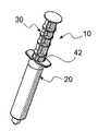
도 1은 플런저 막대의 스템이 그 길이부 상에 배치된 복수 개의 디스크를 구비하는 본 발명에 따라 제조되는 주사기 및 플런저 막대에 대한 사시도이다.
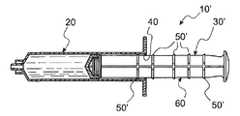
도 2는 도 1에 도시되어 있는 주사기 및 플런저 막대의 단면도이다.
도 2a는 도 2의 주사기 및 플런저 막대와 유사한 주사기 및 플런저 막대에 대한 단면도인데, 여기서 디스크의 에지는 플런저 막대를 주사기 내로 용이하게 변위시키고, 일단 변위되면 플런저 막대가 배럴로부터 제거되는 것을 방지하도록 형성되어 있다.
도 2b는 도 2의 주사기 및 플런저 막대와 유사한 주사기 및 플런저 막대의 단면도이고, 여기서 디스크의 에지는 플런저 막대가 내부로 변위된 후에 주사기로부터 용이하게 변위시키도록 형성되어 있다.
도 2c는 도 2, 도 2a 및 도 2b의 주사기 및 플런저 막대와 유사하지만 디스크 대신에 플런저 막대의 샤프트를 따라 너브(nub)를 구비하는 주사기 및 플런저 막대에 대한 단면도이다.
도 3은 도 1에 도시되어 있는 플런저 막대의 사시도이다.
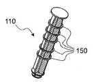
도 4는 주사기 및 플런저 막대에 대한 사시도로서, 여기서 플런저 막대는 도 1의 플런저 막대와 유사하지만, 플런저 막대의 스템 둘레에 배치된 복수 개의 분리 링(breakaway ring)으로 제조된다.
도 5는 도 4에 도시되어 있는 플런저 막대의 사시도이다.
도 6은 적어도 하나의 분리 링이 플런저 막대의 스템으로부터 제거된 도 4에 도시되어 있는 주사기 및 플런저 막대에 대한 사시도이다.
도 7은 주사기 및 플런저 막대에 대한 사시도로서, 여기서 플런저 막대는 도 1의 플런저 막대와 유사하지만, 스템 상에 파동 패턴과 인접한 주사기 배럴 개구 둘레에 구속 엘라스토머 링을 구비하고 있다.
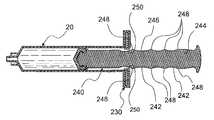
도 8은 도 7에 도시되어 있는 주사기, 플런저 및 엘라스토머 링의 단면도이다.
도 9는 본 발명에 따른 자동 인라인 펄싱 장치에 대한 사시도이다.
도 10은 펄스 단부에서의 장치의 상태를 보여주는 도 9에 도시되어 있는 자동 인라인 펄싱 장치에 대한 단면도이다.
도 11은 펄스를 작동시키기 이전에 부하될 때에 장치의 상태를 보여주는 도 9에 도시되어 있는 자동 펄싱 장치에 대한 단면도이다.
도 12는 펄스 생성 동안의 장치의 상태를 보여주는 도 9에 도시되어 있는 자동 펄싱 장치에 대한 단면도이다.
도 13은 유체 압력 공급원을 제공하도록 주사기가 장치에 부착되어 있는 도 9에 도시되어 있는 장치에 대한 사시도이다.
도 14는 도 9에 도시되어 있는 장치를 위해 펌핑된 유체 공급원을 사용하는 시스템의 개략도이다.
도 15는 본 발명에 따른 제어된 압력 펄스를 제공하기 위한 압착가능 장치에 대한 사시도이다.
도 16은 도 15에 도시되어 있는 장치에 대한 단면도이다.
도 17은 의료 섹션이 제어된 해제 압력 펄스의 단부에서 압착되는 도 14에 도시되어 있는 장치에 대한 단면도이다.
도 18은 본 발명에 따라 제조된 수동 작동식 제어 압력 펄스 장치에 대한 사시도이다.
도 19는 제어된 압력 펄스를 시작하기 이전에 충전되는 도 18에 도시되어 있는 장치에 대한 단면도이다.
도 20은 압력 펄스의 단부에서의 도 18에 도시된 장치에 대한 단면도이다.1 is a perspective view of a syringe and plunger rod made in accordance with the present invention in which the stem of the plunger rod has a plurality of discs disposed on its length;
2 is a cross-sectional view of the syringe and plunger rod shown in FIG. 1.
FIG. 2A is a cross-sectional view of a syringe and plunger rod similar to the syringe and plunger rod of FIG. 2, wherein the edge of the disc is configured to easily displace the plunger rod into the syringe and prevent the plunger rod from being removed from the barrel once displaced It is.
FIG. 2B is a cross-sectional view of the syringe and plunger rod similar to the syringe and plunger rod of FIG. 2, wherein the edge of the disk is configured to easily displace from the syringe after the plunger rod is displaced inward.
FIG. 2C is a cross-sectional view of the syringe and plunger rod similar to the syringe and plunger rod of FIGS. 2, 2A and 2B but with nubs along the shaft of the plunger rod instead of the disc.
3 is a perspective view of the plunger rod shown in FIG. 1.
4 is a perspective view of the syringe and plunger rod, wherein the plunger rod is similar to the plunger rod of FIG. 1, but is made of a plurality of breakaway rings disposed around the stem of the plunger rod.
5 is a perspective view of the plunger rod shown in FIG. 4.
6 is a perspective view of the syringe and plunger rod shown in FIG. 4 with at least one separation ring removed from the stem of the plunger rod.
FIG. 7 is a perspective view of the syringe and plunger rod, wherein the plunger rod is similar to the plunger rod of FIG. 1, but has a restraining elastomer ring around the syringe barrel opening adjacent the wave pattern on the stem.
8 is a cross-sectional view of the syringe, plunger and elastomer ring shown in FIG. 7.
9 is a perspective view of an automatic inline pulsing device according to the present invention.
10 is a cross-sectional view of the automatic inline pulsing device shown in FIG. 9 showing the state of the device at the pulse end.
FIG. 11 is a cross-sectional view of the automatic pulsing device shown in FIG. 9 showing the state of the device when loaded prior to actuating the pulse.
12 is a cross-sectional view of the automatic pulsing device shown in FIG. 9 showing the state of the device during pulse generation.
13 is a perspective view of the device shown in FIG. 9 with a syringe attached to the device to provide a fluid pressure source.
FIG. 14 is a schematic diagram of a system using a pumped fluid source for the apparatus shown in FIG. 9.
15 is a perspective view of a compressible device for providing a controlled pressure pulse in accordance with the present invention.
FIG. 16 is a cross-sectional view of the apparatus shown in FIG. 15.
FIG. 17 is a cross-sectional view of the apparatus shown in FIG. 14 in which the medical section is compressed at the end of the controlled release pressure pulse.
18 is a perspective view of a manually operated controlled pressure pulse device made in accordance with the present invention.
19 is a cross sectional view of the apparatus shown in FIG. 18 that is charged prior to starting a controlled pressure pulse.
20 is a sectional view of the apparatus shown in FIG. 18 at the end of the pressure pulse.
발명의 상세한 설명에서, "기단(proximal)"이라는 용어는 그 위치를 설명하는 문장의 물체에 일반적으로 가장 가까운 장치의 부분을 지시하기 위해 사용된다. "말단(distal)"이라는 용어는 기단 부분에 대향하는 위치를 의미한다. 이제, 일관되게 유사한 도면부호가 유사한 부분을 지시하기 위해 사용되는 도 1 내지 도 20에 도시되어 있는 실시예를 참조하기로 한다.In the description of the invention, the term "proximal" is used to indicate the part of the device that is generally closest to the object of the sentence describing its location. The term "distal" means a position opposite the proximal portion. Reference is now made to the embodiment shown in FIGS. 1-20 where consistently similar reference numerals are used to indicate similar parts.
이제, 본 발명의 주사기/플런저 막대 조합체(10)의 바람직한 실시예가 도시되어 있는 도 1을 참조한다. 조합체(10)는 통상적인 주사기 배럴(20) 및 플런저 막대(30)를 포함하고 있다. 조합체(10)의 현저한 특징은 도 2에 보다 양호하게 도시되어 있는 바와 같이 기단 배럴 구멍 개구(42)에 배치된 보유 링(40)을 구비하는 배럴(20)과, 스템(60)을 따라 배치되고 일반적으로 도면부호 50으로 지시되는 복수 개의 작동 기하학적 형상부인 인터페이스 또는 링을 포함하는 플런저 막대(30)를 포함하는 것이다. 또한, 종래의 주사기의 플런저 막대와 공통되는 바와 같이, 플런저 막대(30)는 스템(60)의 말단부(80)에 부착된 플런저(70)를 구비하고 있다. 말단부(80)는, 배럴(20)이 일반적으로 액체(72)로 지칭되는 액체로 충전된 후에, 플런저 막대(30)가 플런저(70)에 부착될 수 있게 하는 나사 형상부(90)를 구비하는 것에 유의할 것이다. 플런저 막대(30)가 나사부(90)가 더 명확하게 도시되어 있는 도 3에 독립적으로 도시되어 있다.Reference is now made to FIG. 1, where a preferred embodiment of the syringe /
또한, 플런저 막대(30)는 플런저(70)와 스템(60)이 배럴(20) 내로 삽입될 때에 보유 링(40)을 지나 밀어넣어질 수 있는 제1 링(92)을 구비하고 있다. 제1 링(92)은 보유 링(40)을 통해 변위되도록 밀어넣어질 수 있는 크기로 형성되어 있지만, 플런저(70)가 부주의하게 배럴(20) 외부로 변위되지 않도록 촉각으로 식별가능한 정지부를 제공한다.The
각 작동기 링(50)이 보유 링(40)에 의해 방해되는 크기 및 형상으로 형성되어 있다. 또한, 각 작동기 링(50)은 접촉 작동기 기하학적 형상{예를 들어, 보유 링 인터페이스(50)}을 보유 링(40)을 지나 변위시키도록 초과되어야만 하는 미리결정된 힘이 필요한 크기 및 형상으로 형성되어 있다. 이러한 이유로, 배럴(20) 내의 유체는 접촉 링(50)이 보유 링(40)을 통해 해제가능하게 변위될 때에, 미리결정된 힘으로 인한 결과적인 가속도 및 속도에 의해 변위된다. 일반적으로, 결과적인 가속도 및 속도는 액체(72)를 난류형태로 플러싱하도록 관련 카테터 시스템을 통해 주사기 배럴(20)로부터 방출되는 액체에 대한 것이다. 이러한 방식으로, 접촉 링(50)이 보유 링(40)을 지나 변위될 때마다, 가압된 액체(72)의 펄스가 카테터 시스템 내로 퍼지되어 그것을 통해 액체(72)의 난류 플러싱 펄스를 제공한다.Each
또한, 링(50) 중 보다 기단의 링(94)은, 작동 사용 링(94)으로 인한 펄스가 조합체(10)로부터 액체(72)에 의해 제공되는 마지막 펄스라는 표시(reminder)를 제공하도록 보다 말단의 링(50)보다 큰 힘이 필요한 크기 및 형상으로 형성되어 있다. 이러한 이유로, 링(94)은 이하에서 표시 링(94)으로 불리울 수 있다. 만약, 플런저 막대(30)가 표시 링(94)을 보유 링(40)을 지나 변위시키도록 배럴(20) 내로 충분히 멀리 변위되지 않는다면, 관련된 카테터 시스템 내에서 어떠한 백플로우(back flow) 또는 리플럭스(reflux)가 발생되지 않는 것에 유의하라. 스템(60)의 기단부(98)가 플런저 막대(30)에 대한 손가락 힘의 적용을 용이하게 하는 볼록 또는 돔 형상이라는 것을 주목하라.In addition, the more
또한, 링(50)은 균일하게 이격되어야 할 필요가 없다는 것에 유의하라. 예로서, 제1 링(92)과 인접한 최기단 링(50) 사이의 공간(99)이 일반적으로 도면부호 50으로 지칭되는 다른 링들 사이의 공간에 비해 비교적 크다. 이것은 적절한 카테터 작동을 보장하는 카테터 혈액 유동을 위한 통상적인 샘플에 사용될 수 있는 "펄스 없는" 부분을 제공한다.Also note that the
이제, 통상적인 주사기 배럴(20)과 플런저 막대(30')의 조합체(20')가 도시되어 있는 도 2a를 살펴본다. 플런저 막대(30')는 플런저 막대(30)와 유사하고, 그 길이를 따라 배치된 일련의 작동기 링(50')을 포함하고 있다. 그러나, 조합체(10')의 경우에, 링(50')은 배럴(20)을 보유 링을 통해 기단부로 변위시키기 보다는 배럴(20) 내로{그리고 보유 링(40)을 통해 말단부로} 보다 용이하게 변위되는 크기 및 형상으로 형성되어 있다(도 2a 참조). 이것은 플런저 막대(30')가 일단 단일 사용 적용을 촉진시키기 위해 사용되면, 배럴(20)로부터 용이하게 제거되지 않는 조건을 충족시킨다.Reference is now made to FIG. 2A where a combination 20 'of a
한편, 이러한 조합체를 재충전시키고 재사용하는 것이 소망될 수 있다. 이러한 경우에, 제3 조합체(10")의 플런저 막대(30")를 말단부보다 기단부를 향해 보다 용이하게 변위시키는 것이 소망된다. 이러한 경우에, 스템(60)을 따라 배치된 작동 링(50")은 도 2b에 도시되어 있는 바와 같이 성형되어 있다.On the other hand, it may be desirable to recharge and reuse these combinations. In this case, it is desired to displace the
도 2에 도시되어 있는 링(50)은 도 2c의 조합체(12)에서 볼 수 있는 바와 같이 플런저 막대(32) 상의 너브(52)에 의해 대체될 수 있다. 링(50)을 보유 링(40)을 지나 변위시키기 위해 필요한 것과 유사한 힘을 필요하도록 너브(52)를 소정 크기 및 형상으로 형성함으로써, 원하는 난류를 생성시키는 효과가 열화되는 일 없이 너브(52)에 의한 링(50)의 대체가 수행될 수 있다.The
본 발명의 조합체(110)에서 볼 수 있는 바와 같은 다른 실시예가 도 4 내지 도 6에 도시되어 있다. 조합체(10)에서와 같이, 조합체(110)는 통상적인 주사기 배럴(20)을 포함하고 있다. 주사기 배럴(20)은 보유 링(40)과 관련된 기단 입구 구멍(122)을 구비하고 있다는 것에 유의하라. 도 4 및 도 5에 도시되어 있는 바와 같이, 관련된 플런저 막대(30)는 또한 대체로 도면부호 150으로 지칭되고 플런저 막대(130)의 스템(60)을 따라 배치된 일련의 작동기 링을 포함하고 있다. 그러나, 원하는 압력 펄스를 생성시키도록 배럴(20)의 보유 링(40)을 통해 밀어넣어지는 크기 및 형상으로 형성되기 보다는, 링(150)은 이것이 배럴 입구 구멍(42) 내로 변위될 때에 각 작동 링(150)이 스템(60)으로부터 전단 변형되는 방식으로 스템(60)에 부착되어 있다.Another embodiment as seen in the
스템(60)으로부터의 별개의 작동 링(150)에서의 전단력은, 조합체(10)의 보유 링(40)을 통과하는 변위력과 유사하게, 하류 카테터 시스템으로부터 원하지 않는 오염물을 방출 및 퍼지하기 위해 소망하는 난류 유동을 공급하는 미리결정된 가속도 및 속도를 제공하도록 기하학적 및 기계적으로 설계된다. 도 6에서, 보다 말단에 배치된 제1 작동기 링(150)은 도 6의 구멍 외부에서 보다 기단에 배치된 제2 작동기 링(150)에 의해 포획되는 것으로 도시되어 있는 것에 유의하라. 전단된 작동 링(150)의 축적이 주사기가 완전히 방출되는 것을 방지하기 위해 사용된다.The shear force in the
본 발명의 또 다른 실시예가 도 7 및 도 8에 도시되어 있는 통상적인 주사기 배럴(20)을 사용할 수 있는 조합체(210)로서 도시되어 있다. 배럴(20)에 추가하여, 조합체(210)는 탄성 제한기(230)와, 스템(242)을 구비하는 플런저 막대(240)를 포함하고 있다. 스템(242)은 각각 도면부호 244로 지시되는 복수 개의 세장형 측부 부재를 포함하고 있다. 각 측부 부재는 도면부호 246으로 지시되는 파형 외부 에지를 구비하고 있다. 파형의 고점부가 대체로 도면부호 248로 지시된다.Another embodiment of the present invention is shown as a
제한기(230)는 배럴 입구 구멍(42) 둘레에 포트를 제공하도록 형성 및 구성되어 있다(도 1 및 도 2 참조). 제한기 입구 구멍(250)이 제한기(230)와 각 고점부(248) 사이의 충돌 시에 플런저 막대(240)의 내측방향 변위를 방해하는 크기 및 형상으로 형성되어 있다. 탄성 제한기(230)의 선택된 경도계와, 고점부(248)와 구멍(250)의 충돌 기하학적 형상의 조합이 플런저 막대(240)의 추가 변위를 위한 미리결정된 힘을 요구하도록 조합된다. 이 미리결정된 힘은 보유 링(40)을 지나 플런저 막대(30)를 변위시키기 위해 필요한 힘에 상응한다(도 1 내지 도 3 참조). 이러한 방식으로, 고점부(248)가 제한기(230)의 구멍(250)을 통해 변위될 때마다, 부착된 카테터 시스템을 퍼지하기 위한 난류 유동을 제공하는 압력 펄스가 생성된다.The
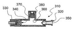
본 발명에 따라 제조된 인라인 자동 펄스 장치(310)가 도시되어 있는 도 9 내지 도 12를 참조한다. 도 9에 도시되어 있는 바와 같이, 장치(310)는 상류 또는 기단 연결부(320)를 포함하는데, 그 내부로 액체 공급원으로부터의 액체가 제공된다. 또한, 장치(310)는 하류 카테터 시스템에 연결될 수 있는 출력 포트 및 커넥터(330)를 포함하고 있다. 적절한 작동을 위해, 공급원으로부터 사용가능한 액체 압력은 장치(310)에 의해 발산되는 퍼지 액체 펄스의 원하는 압력보다 커야만 한다.Reference is made to FIGS. 9-12 where an inline
도 10에 도시되어 있는 바와 같이, 압력이 원하는 압력 미만인 경우에, 압력 감응성 밸브(340)가 배치되어 출력 포트 및 커넥터(330)를 폐쇄시킨다. 소정 수준의 유동까지 인플로우를 지연시키고 백플로우를 방해하도록 체크 밸브(350)가 기단 연결부(320)로부터 오직 말단에 있다. 압력 감응성 밸브(340)와 체크 밸브(350) 사이에는 펄스 저장 챔버(360)가 중간에 배치된다. 밸브(330)가 폐쇄될 때에 소정 체적의 액체를 저장하도록 챔버(360) 내에서 작용하는 피스톤(370)과 스프링(380)이 챔버(360) 내에 배치된다.As shown in FIG. 10, when the pressure is below the desired pressure, a pressure
압력 민감성 밸브(340)를 선택할 때에, 아래에서 설명되는 목적을 위해 미리결정된 압력 차이를 갖는 개방 압력 대 폐쇄 압력 히스테리시스를 갖는 밸브가 선택되어야 한다. 압력 차이는 높은 해제 압력과 낮은 폐쇄 압력 사이의 차이로 규정된다. 높은 압력은, 부착된 카테터 시스템으로부터 원하는 양의 재료를 퍼지하는 하류 난류를 일으키는 충분한 힘 및 유동을 갖는 압력 펄스를 생성시키는 압력이다. 낮은 압력은 챔버(360)로부터 액체를 제거한 후에, 장치(310) 내의 압력이 저하되는 압력이다. 낮은 압력까지 떨어지는 내부(310)의 압력에 있어서, 공급원으로부터의 인플로우는 출력 포트 및 커넥터(330)를 통한 외부 유동보다 더 낮은 유량으로 제한되어야 한다는 것에 유의하라.When selecting the pressure
장치(310)의 작동 단계는, 챔버(360)가 비어 있고 스프링(380)이 감압되며, 밸브(350)가 폐쇄되는 도 10에 도시된 시작 상태를 구현하는 것으로 도시되어 있다. 챔버(360)의 후속 충전이 도 11에 도시되어 있다. 스프링(380)이 완전히 가압되어 이에 의해 장치(310)로부터 액체를 방출할 때에, 밸브(340)가 개방된다. 물론, 일단 밸브(350)가 폐쇄된 후에, 펄스 사이클이 반복된다.The operating phase of the
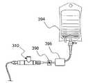
장치(310)의 가압 유체 공급원이 도 13 및 도 14에 도시되어 있다. 도 13에는, 통상적인 주사기(390)가 기단 연결부(320)에 부착되어 있다. 공급원 압력이 관련된 플런저 막대(392)를 변위시키는 힘에 의해 제공된다. 밸브(350)를 작동시키기 이전에 챔버(360)를 충분히 방출시키기 위해 충분한 압력이 필요하다는 것에 유의하라.A pressurized fluid source of
도 14에 있어서, 염류 백(304), 펌프(396) 및 가변 액체 유동 제한기(398)를 포함하는 보다 정교한 압력 공급원 시스템이 도시되어 있다. 백(394)으로부터의 공급원 액체가 펌프(396)에 의해 흡인 및 펌핑되어, 밸브(350)를 개방시키기 위해 필요한 높은 압력과 동일하거나 더 큰 압력을 제공한다. 가변 제한기는 장치(310) 출력 펄스 속도를 결정하는 펌프(396) 대 장치(310) 액체 전달 속도를 결정하도록 설정된다.In FIG. 14, a more sophisticated pressure source system is shown that includes a salt bag 304, a
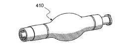
이제, 본 발명에 따라 제조된 인라인 핀치 또는 압착 펌프(410)가 도시되어 있는 도 15 내지 도 17을 참조한다. 도 16에 도시되어 있는 바와 같이, 장치(410)는 상류 또는 기단 연결부(420)를 포함하고, 이 내부로 액체 공급원으로부터의 액체가 제공된다. 또한, 장치(410)는 하류 카테터 시스템에 연결될 수 있는 출력 포트 및 커넥터(430)를 포함하고 있다. 적절한 작동을 위해, 공급원으로부터 사용가능한 액체 압력은 압착에 의해 용이하게 충전 및 퍼지될 수 있는 크기 및 형상으로 형성되는 팽창가능한 튜브(440)의 충전 압력보다 커야만 한다.Reference is now made to FIGS. 15-17 where an inline pinch or
도 16에 도시되어 있는 바와 같이, 압력 감응성 밸브(340){또한, 전술한 장치(310)의 도 11 내지 도 13을 참조}가, 압력이 미리결정된 압력 미만일 때에, 출력 포트 및 커넥터(430)를 폐쇄시키도록 배치되어 있다. 백플로우를 방해하도록 체크 밸브(450)가 기단 연결부(420)로부터 말단에 있다. 튜브(440)는 장치(410)가 작동될 때에 펄스 유동량을 정하는 저장 매체를 제공한다. 작동시키기 위해, 튜브(440)는 밸브(340)가 본 발명에 따른 압력 펄스를 제공하도록 개방될 때까지 압착된다. 계속된 반사적 압착이 밸브(340)를 통해 액체를 분배하여, 부착된 카테터 시스템을 퍼지하도록 충분한 난류 및 압력을 갖는 액체 유동의 맥동을 생성시킨다. 공급원 액체의 압력은 튜브(440)를 충전시키기에 충분히 높은 압력만을 필요로 하고, 튜브(440)는 다소 네거티브한 충전 압력 요건을 제공하기 위해 충분한 고유한 구조 메모리를 가질 수 있다. 이 동일한 메모리는 튜브(440) 내의 액체 압력을 감소시켜서, 밸브(340)가 펄스 생성 사이클 말미에서 폐쇄되게 한다.As shown in FIG. 16, the pressure sensitive valve 340 (also see FIGS. 11-13 of the
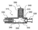
본 발명에 따른 카테터 시스템을 퍼지하기 위한 수동으로 손가락에 의해 생성되는 제어된 압력 펄스를 제공하는 다른 장치(510)가 도 18 내지 도 20에 도시되어 있다. 도 19에 도시되어 있는 바와 같이, 장치(510)는 상류 또는 기단 연결부(520)를 포함하고, 그 내부로 액체 공급원으로부터의 액체가 제공된다. 또한, 장치(510)는 하류 카테터 시스템에 연결될 수 있는 출력 포트 및 커넥터(530)를 포함하고 있다. 적절한 작동을 위해, 공급원으로부터 사용가능한 액체 압력은 스프링 피스톤 조립체(540)의 충전 압력보다 커야만 한다. 조합체(540)는 감압 버튼 및 막대(550)와, 압축가능한 스프링(560)과, 플런저(570)를 포함하고 있다. 플런저(570)는 기단 연결부(520)와 출력 포트(530) 사이의 액체 연통을 위해 배치된 중공형 액체 유동 챔버(590)와 직교하게 연통하는 중공형 수직 챔버(580)로부터의 액체를 배출하도록 소정의 크기 및 형상으로 형성된다. 수직 챔버(580)에 저장되고 플런저(570)의 변위 시에 방출되는 액체의 양은 하류 카테터 시스템으로 전달되는 액체의 펄스 체적을 결정한다.Another
도 19에 도시되어 있는 바와 같이, 압력 감응성 밸브(340)(전술한 장치(310)의 도 11 내지 도 13을 참조)는, 압력이 소정 압력 미만일 때에, 출력 포트와 커넥터(530)를 폐쇄하도록 배치된다. 백플로우를 방해하도록 체크 밸브(450)가 기단 연결부(520)로부터 말단에 있다. 장치(510)를 작동시키기 위해, 버튼(550)을 눌러서 밸브(340)를 개방함으로써, 본 발명에 따른 압력 펄스를 제공한다. 일관성 있는 반사성 누름 버튼(550)이 밸브(340)를 통해 액체를 분배하여 부착된 카테터 시스템을 퍼지시키기 위해 충분한 난류 및 압력을 가진 액체의 맥동 유동을 생성시킨다. 공급원 액체의 압력은 챔버(580)를 충전시키기 위해 충분히 높은 압력이어야만 하고, 스프링(560)과의 조합체(540)는 챔버(590) 내에 네거티브 충전 압력을 제공하도록 충분한 고유의 구조적 메모리를 가져야만 한다. 이 동일한 메모리는 챔버(590) 내의 액체 압력을 감소시켜서, 밸브(340)가 펄스 생성 사이클의 말미에서 폐쇄되게 한다.As shown in FIG. 19, the pressure sensitive valve 340 (see FIGS. 11-13 of the
장치(510)를 작동시키기 위해, 챔버(580)는 커넥터(520)를 통해 제공되는 액체로 충전될 수 있다. 밸브(340)를 개방시키기 위해 필요한 힘을 제공하기 위해 버튼(550)을 누르고, 원하는 퍼지 압력 펄스를 생성시키기 위해 도 20에 도시되어 있는 바와 같이 챔버(580)로부터 액체가 퍼지될 때까지, 반사적으로 그 후에 계속하여 버튼을 누른다. 일단 조합체(540)를 완전히 누른 후에, 버튼(550) 상의 힘이 후속 압력 펄스를 생성시키기 위한 챔버(580)의 재충전을 허용하도록 제거된다.To operate the
본 발명은 본 발명의 기술적 사상 또는 본질적 특징에서 벗어나지 않는 한 다른 특정 형태로 구현될 수 있다. 따라서, 본 발명의 실시예는 모든 측면에서 제한적인 것이 아니라 예시적인 것으로 고려되어야 하고, 본 발명의 보호범위는 전술한 발명의 상세한 설명이 아니라 첨부된 특허청구범위에 의해 규정되며, 특허청구범위의 균등의 범위 및 의미 내에 있는 모든 변경은 본 발명의 보호범위 내에 포함되는 것으로 의도된다.The present invention can be implemented in other specific forms without departing from the spirit or essential features of the invention. Accordingly, the embodiments of the present invention should be considered in all respects as illustrative and not restrictive, and the protection scope of the present invention is defined by the appended claims rather than the foregoing description of the invention, and the scope of the claims. All changes which come within the meaning and range of equivalency are intended to be included within the scope of protection of the present invention.
Claims (12)
Translated fromKorean플러시 유체 공급원과,
미리결정된 체적의 유체를 보유하기 위한 용기와,
용기와 카테터 시스템 사이의 유체 유동 연통을 제어가능하게 중단시키도록 상호연결된 밸브 기구와,
상기 밸브 기구의 개방 및 폐쇄를 제어하는 검지 작동기로서, 용기로부터 유체의 충분한 난류 유동을 일으키는 소정의 미리결정된 압력에서 상기 밸브 기구를 개방시키고, 또한 개방 압력보다 낮은 다른 미리결정된 압력에서 밸브 기구가 폐쇄되도록 작동 히스테리시스를 갖는, 검지 작동기와,
적어도, 밸브 기구를 개방시키기 위해 필요한 용기 내의 압력을 발생시키기에 충분한 유체력을 제공하기 위한 수단과,
상기 수단의 작동으로부터 수용되는 에너지를 저장하고, 저장된 에너지를 밸브 개방시에 해제하여, 용기 내의 압력이 다른 압력을 초과하는 시간 의존하는 기간 동안에 난류 플러싱 유체 압력 및 유동을 제공하는, 메모리 요소를 포함하는
제어되고 일정한 추진-중단 맥동 유동을 제공하는 장치.A device for providing a controlled and constant propulsion-stop pulsating flow of turbulent flushing pressure and flow sufficient to substantially purge unwanted residue from a line in a catheter system, the apparatus comprising:
Flush fluid source,
A container for holding a predetermined volume of fluid,
A valve mechanism interconnected to controllably stop fluid flow communication between the vessel and the catheter system,
A detection actuator for controlling the opening and closing of the valve mechanism, the detection mechanism opening the valve mechanism at a predetermined predetermined pressure causing sufficient turbulent flow of fluid from the vessel and closing the valve mechanism at another predetermined pressure lower than the opening pressure. The detection actuator, preferably having hysteresis,
At least means for providing a fluid force sufficient to generate pressure in the vessel necessary to open the valve mechanism;
A memory element that stores energy received from the operation of the means and releases the stored energy upon valve opening to provide turbulent flushing fluid pressure and flow for a time dependent period in which the pressure in the vessel exceeds another pressure. doing
A device that provides controlled and constant propulsion-stop pulsating flow.
(i) 상기 공급원은 주사기 배럴 내에 담겨진 유체를 포함하고,
(ii) 상기 용기는 주사기의 배럴의 말단부를 포함하는 하우징과, 상기 배럴 내에서 활주가능하게 변위되도록 배치된 플런저 막대에 부착된 플런저를 포함하고, 상기 배럴은 그 기단부 상의 보유 링을 더 포함하며, 상기 플런저는 상기 플런저와 연관된 기단에 배치된 입구 디스크를 포함하고, 상기 입구 디스크와 보유 링은 배럴로부터 플런저가 의도하지 않게 제거되는 것을 방지하는 촉각으로 식별가능한 정지부를 제공하도록 협동하며,
(iii) 상기 플런저 막대는 상기 플런저 및 입구 디스크에 대해 기단에 배치된 밸브 작동 디스크를 포함하는 하나 이상의 검지 작동기를 더 포함하고, 상기 밸브 작동 디스크는, 밸브 작동 디스크가 보유 링을 통해 밀어넣어지는 경우에 난류 유동에 필요한 압력을 생성시키도록 보유 링을 지나 변위될 때에, 제어되고 일정한 힘이 필요한 크기 및 형상으로 형성되며,
(iv) 상기 수단은 보유 링을 지나 작동 디스크를 변위시키기에 충분한 힘을 제공하도록 힘이 수동으로 가해지는 기단에 배치된 버튼을 포함하는 상기 플런저 막대를 포함하고,
(v) 상기 메모리 요소는 작동 디스크를 보유 링을 지나 변위시키기 위해 수동으로 가해지는 힘으로부터 기인하는 일정한 반사력을 포함하는
제어되고 일정한 추진-중단 맥동 유동을 제공하는 장치.The method of claim 1,
(i) the source comprises a fluid contained within a syringe barrel,
(ii) the container comprises a housing comprising a distal end of a barrel of a syringe, and a plunger attached to a plunger rod arranged to slidably displace within the barrel, the barrel further comprising a retaining ring on its proximal end; The plunger comprises an inlet disc disposed at an end associated with the plunger, the inlet disc and retaining ring cooperating to provide a tactilely identifiable stop that prevents the plunger from being inadvertently removed from the barrel,
(iii) the plunger rod further comprises one or more detection actuators comprising a valve actuation disk proximate to the plunger and an inlet disc, the valve actuation disk being pushed through a retaining ring. When displaced past the retaining ring to create the pressure required for turbulent flow, a controlled, constant force is formed in the required size and shape,
(iv) said means comprises said plunger rod comprising a button disposed at a proximal end to which force is manually applied to provide sufficient force to displace the working disk past the retaining ring,
(v) the memory element includes a constant reflecting force resulting from a force applied manually to displace the working disk past the retaining ring.
A device that provides controlled and constant propulsion-stop pulsating flow.
(i) 상기 공급원은 관련된 카테터 시스템을 퍼지하기 위해 유체의 단일 추진-중단 펄스 체적보다 대체로 큰 액체의 수용을 위한 체적을 갖는 유체 저장소를 포함하고,
(ii) 상기 용기는 공급원 저장소로부터 일방향 밸브를 통한 연통 경로와, 제2 일방향 밸브를 통한 카테터 시스템으로의 다른 연통 경로를 포함하는 중공형 원통형 베슬을 포함하며,
(iii) 상기 밸브 기구는 베슬 내의 유체로서, 공급원으로부터 흡인된 또는 카테터 시스템 내로 분배된 액체를 변위시키는 크기 및 형상으로 구성된 플런저를 포함하고,
(iv) 상기 검지 작동기는 플런저 막대와 플런저의 기단부에 배치된 보유 링과, 플런저를 수동으로 변위시키도록 배치된 관련된 수동 작동기 버튼을 포함하고, 밸브 작동 디스크가 상기 플런저에 대해 기단에 배치되고 그것을 관통하도록 밀어넣어질 때까지 보유 링 기단에 배치되며, 상기 보유 링은 플런저 상의 힘이 용기로부터 카테터 시스템으로의 유체의 충분한 난류 유동을 제공하는 압력을 발생시킬 때까지, 플런저의 변위를 지연시키고,
(v) 상기 수단은 베슬로부터의 유체를 분배하기 위해 수동으로 눌러지는 플런저와 관련된 버튼을 포함하고, 상기 수단은 후속하는 압력 펄스 사이클 동안에 검지 작동기를 재설정하고 베슬을 재충전시키는 밸브 작동 디스크와 플런저를 복귀시키도록 분배 동안에 플런저 변위의 에너지를 저장하는 메모리 요소를 더 포함하는
제어되고 일정한 추진-중단 맥동 유동을 제공하는 장치.The method of claim 1,
(i) the source comprises a fluid reservoir having a volume for the receipt of a liquid that is generally larger than a single push-stop pulse volume of fluid to purge the associated catheter system,
(ii) the vessel comprises a hollow cylindrical vessel comprising a communication path from the source reservoir through the one-way valve and another communication path through the second one-way valve to the catheter system,
(iii) the valve mechanism comprises a plunger configured as a fluid in the vessel, the plunger configured in size and shape to displace liquid drawn from the source or dispensed into the catheter system,
(iv) the detection actuator includes a plunger rod and a retaining ring disposed at the proximal end of the plunger and an associated manual actuator button arranged to manually displace the plunger, the valve actuating disk being positioned proximate to the plunger and Positioned at the base of the retaining ring until it is pushed through, which retains displacement of the plunger until the force on the plunger generates a pressure that provides sufficient turbulent flow of fluid from the vessel to the catheter system,
(v) said means includes a button associated with a plunger that is manually pressed to dispense fluid from the vessel, said means being capable of resetting the valve actuator disk and the plunger for resetting the detection actuator and refilling the vessel during subsequent pressure pulse cycles. Further comprising a memory element for storing energy of the plunger displacement during dispensing to return
A device that provides controlled and constant propulsion-stop pulsating flow.
(i) 상기 공급원은 미리결정된 압력 및 유동으로 분배되는 유체를 제공하는 압력 제공 장치로부터 상류에 있는 유체 저장소를 포함하고,
(ii) 상기 용기는 유동 제한기를 통해 상기 압력 제공 장치와, 그리고 선택된 압력 감응성 밸브를 통해 상기 카테터 시스템과 연통하는 베슬을 포함하며,
(iii) 밸브 기구는 미리결정된 압력에서 용기로부터 카테터 시스템으로 유체를 분배하도록 개방되고 다른 미리결정된 압력에서 폐쇄되는 압력 감응성 밸브를 포함하고,
(iv) 상기 검지 작동기는 미리결정된 압력에서 밸브 개방 작동을 포함하고, 다른 미리결정된 압력에서 밸브 폐쇄 작동을 포함하는 압력 감응성 밸브의 부분이며,
(v) 상기 수단은 상기 용기를 충전시키고 용기 내의 압력을 미리결정된 압력까지 상승시키도록 상기 유동 제한기를 통해 작용하는 미리결정된 압력 및 유동으로 분배되는 유체를 제공하는 압력 제공 장치를 포함하고,
(vi) 상기 메모리 요소는 플런저 요소 기단에 배치된 압축가능한 요소를 포함하고, 상기 플런저 요소는 유동 제한기를 통해 펌프로부터의 압력 및 유동에 의해 변위되어 제어되고 일정한 압력 및 체적을 축적시킴으로써, 카테터 시스템을 퍼지하기 위한 목표 압력 펄스를 제공하는
제어되고 일정한 추진-중단 맥동 유동을 제공하는 장치.The method of claim 1,
(i) the source comprises a fluid reservoir upstream from a pressure providing device providing a fluid dispensed at a predetermined pressure and flow,
(ii) the vessel comprises a vessel in communication with the pressure providing device via a flow restrictor and the catheter system via a selected pressure sensitive valve,
(iii) the valve mechanism includes a pressure sensitive valve that is open to dispense fluid from the vessel to the catheter system at a predetermined pressure and closes at another predetermined pressure,
(iv) the detection actuator is a portion of a pressure sensitive valve comprising a valve opening operation at a predetermined pressure and a valve closing operation at another predetermined pressure,
(v) the means comprises a pressure providing device for providing a fluid dispensed with a predetermined pressure and flow acting through the flow restrictor to fill the vessel and raise the pressure in the vessel to a predetermined pressure,
(vi) the memory element comprises a compressible element disposed at the base of the plunger element, the plunger element being displaced and controlled by pressure and flow from the pump through a flow restrictor, thereby accumulating a constant pressure and volume, thereby providing a catheter system To provide a target pressure pulse to purge
A device that provides controlled and constant propulsion-stop pulsating flow.
상기 장치는 펌프를 포함하는
제어되고 일정한 추진-중단 맥동 유동을 제공하는 장치.The method of claim 4, wherein
The apparatus includes a pump
A device that provides controlled and constant propulsion-stop pulsating flow.
상기 장치는, 추진-중단 맥동 유동을 생성시키도록 상기 밸브가 상기 작동기에 의해 개방되는 미리결정된 압력을 제공하는 수단으로서 수동으로 압착되는 튜브를 포함하는
제어되고 일정한 추진-중단 맥동 유동을 제공하는 장치.The method of claim 4, wherein
The apparatus includes a tube that is manually squeezed as a means for providing a predetermined pressure at which the valve is opened by the actuator to produce a propulsive-stop pulsating flow.
A device that provides controlled and constant propulsion-stop pulsating flow.
(a) (i) 플러시 유체 공급원과,
(ii) 미리결정된 체적의 액체를 보유하기 위한 용기와,
(iii) 용기와 카테터 시스템 사이의 유체 유동 연통을 제어가능하게 중단시키도록 상호연결된 밸브 기구와,
(iv) 상기 밸브 기구의 개방 및 폐쇄를 제어하는 검지 작동기로서, 용기로부터 유체의 충분한 난류 유동을 일으키는 소정의 미리결정된 압력에서 상기 밸브 기구를 개방시키고, 개방 압력보다 낮은 다른 미리결정된 압력에서 밸브 기구가 폐쇄되도록 작동 히스테리시스를 갖는, 검지 작동기와,
(v) 밸브 기구를 개방시키기 위해 필요한 용기 내의 압력을 발생시키도록 적어도 충분한 유체 압력을 제공하기 위한 수단과,
(vi) 수단의 작동으로부터 수용되는 에너지를 저장하고, 저장된 에너지를 밸브 개방시에 해제하여, 용기 내의 압력이 다른 압력을 초과하는 시간에 의존하는 기간 동안에 난류 플러싱 유체 압력 및 유동을 제공하는, 메모리 요소를 포함하는
장치를 제공하는 단계와,
(b) 용기를 공급원으로부터의 유체로 충전하는 단계와,
(c) 용기 내에 유체 개방 압력을 생성시켜서 밸브를 소정의 미리결정된 압력에서 개방시키도록 수단을 통해 힘을 제공하는 단계와,
(d) 카테터 시스템 내로 미리결정된 기간 동안에 미리결정된 난류 압력 및 유동을 갖는 플러싱 유체를 분배하는 단계와,
(e) 용기 내의 압력이 다른 미리결정된 압력 미만의 수준으로 감소된 후에 밸브를 폐쇄시키는 단계를 포함하는
제어된 추진-중단 맥동 유동을 제공하기 위한 방법.A method for providing controlled turbulent flushing pressure and flow of controlled propulsion-stop pulsating flow in a catheter system to purge unwanted residue from the line, the method comprising:
(a) (i) a flush fluid source,
(ii) a container for holding a predetermined volume of liquid,
(iii) a valve mechanism interconnected to controllably stop fluid flow communication between the vessel and the catheter system,
(iv) a detection actuator that controls the opening and closing of the valve mechanism, the detection mechanism opening the valve mechanism at a predetermined predetermined pressure causing sufficient turbulent flow of fluid from the vessel, and at another predetermined pressure lower than the opening pressure. The detection actuator, having an actuation hysteresis so that the
(v) means for providing at least sufficient fluid pressure to generate pressure in the vessel necessary to open the valve mechanism;
(vi) a memory that stores energy received from the operation of the means and releases the stored energy upon valve opening to provide turbulent flushing fluid pressure and flow for a period of time depending on the time in which the pressure in the vessel exceeds other pressures. Containing the element
Providing a device,
(b) filling the container with fluid from a source,
(c) providing a force through the means to create a fluid opening pressure in the container to open the valve at a predetermined predetermined pressure;
(d) dispensing a flushing fluid having a predetermined turbulent pressure and flow for a predetermined period of time into the catheter system,
(e) closing the valve after the pressure in the vessel has been reduced to a level below another predetermined pressure.
A method for providing controlled propulsion-stop pulsating flow.
사용중의 부분들과 연관되는 이하의 특정 단계로서,
(a) (i) 상기 공급원은 주사기 배럴 내에 담겨진 유체를 포함하고,
(ii) 상기 용기는 주사기의 배럴의 말단부를 포함하는 하우징과, 상기 배럴 내에서 활주가능하게 변위되도록 배치된 플런저 막대에 부착된 플런저를 포함하고, 상기 배럴은 그 기단부 상의 보유 링을 더 포함하며, 상기 플런저는 상기 플런저와 연관된 기단에 배치된 입구 디스크를 포함하고, 상기 입구 디스크와 보유 링은 배럴로부터 플런저가 의도하지 않게 제거되는 것을 방지하는 촉각으로 식별가능한 정지부를 제공하도록 협동하며,
(iii) 상기 플런저 막대는 상기 플런저 및 입구 디스크에 대해 기단에 배치된 밸브 작동 디스크를 포함하는 하나 이상의 검지 작동기를 더 포함하고, 상기 밸브 작동 디스크는, 밸브 작동 디스크가 보유 링을 통해 밀어넣어지는 경우에 난류 유동에 필요한 압력을 생성시키도록 보유 링을 지나 변위될 때에, 제어되고 일정한 힘이 필요한 크기 및 형상으로 형성되며,
(iv) 상기 수단은 보유 링을 지나 작동 디스크를 변위시키기에 충분한 힘을 제공하도록 힘이 수동으로 가해지는 기단에 배치된 버튼을 포함하는 상기 플런저 막대를 포함하고,
(v) 상기 메모리 요소는 작동 디스크를 보유 링을 지나 변위시키기 위해 수동으로 가해지는 힘으로부터 기인하는 일정한 반사력을 포함하는
장치를 제공하는 단계와,
(b) 플러싱 유체로 충전된 배럴을 포함하는 주사기를 카테터 시스템에 부착시키는 단계와,
(c) 하나의 밸브 작동 디스크를 보유 링을 지나 변위시키도록 플런저 막대 버튼 상에 충분한 힘을 가하고, 목표 압력 펄스를 제공하기 위해 플런저 막대를 반사적으로 계속 변위시키는 단계를 포함하는
제어된 추진-중단 맥동 유동을 제공하기 위한 방법.The method of claim 7, wherein
As the following specific steps associated with the parts in use,
(a) (i) the source comprises a fluid contained within a syringe barrel,
(ii) the container comprises a housing comprising a distal end of a barrel of a syringe, and a plunger attached to a plunger rod arranged to slidably displace within the barrel, the barrel further comprising a retaining ring on its proximal end; The plunger comprises an inlet disc disposed at an end associated with the plunger, the inlet disc and retaining ring cooperating to provide a tactilely identifiable stop that prevents the plunger from being inadvertently removed from the barrel,
(iii) the plunger rod further comprises one or more detection actuators comprising a valve actuation disk proximate to the plunger and an inlet disc, the valve actuation disk being pushed through a retaining ring. When displaced past the retaining ring to create the pressure required for turbulent flow, a controlled, constant force is formed in the required size and shape,
(iv) said means comprises said plunger rod comprising a button disposed at a proximal end to which force is manually applied to provide sufficient force to displace the working disk past the retaining ring,
(v) the memory element includes a constant reflecting force resulting from a force applied manually to displace the working disk past the retaining ring.
Providing a device,
(b) attaching a syringe comprising a barrel filled with flushing fluid to the catheter system,
(c) applying sufficient force on the plunger rod button to displace one valve actuating disc past the retaining ring, and reflectively displacing the plunger rod to provide a target pressure pulse;
A method for providing controlled propulsion-stop pulsating flow.
사용중의 부분들과 연관되는 이하의 특정 단계로서,
(a) (i) 상기 공급원은 관련된 카테터 시스템을 퍼지하기 위해 유체의 단일 추진-중단 펄스 체적보다 대체로 큰 액체의 수용을 위한 체적을 갖는 유체 저장소를 포함하고,
(ii) 상기 용기는 공급원 저장소로부터 일방향 밸브를 통한 연통 경로와, 제2 일방향 밸브를 통한 카테터 시스템으로의 다른 연통 경로를 포함하는 중공형 원통형 베슬을 포함하며,
(iii) 상기 밸브 기구는 베슬 내의 유체로서, 공급원으로부터 흡인된 또는 카테터 시스템 내로 분배된 액체를 변위시키는 크기 및 형상으로 구성된 플런저를 포함하고,
(iv) 상기 검지 작동기는 플런저 막대와 플런저의 기단부에 배치된 보유 링과, 플런저를 수동으로 변위시키도록 배치된 관련된 수동 작동기 버튼을 포함하고, 밸브 작동 디스크가 상기 플런저에 대해 기단에 배치되고 그것을 관통하도록 밀어넣어질 때까지 보유 링 기단에 배치되며, 상기 보유 링은 플런저 상의 힘이 용기로부터 카테터 시스템으로의 유체의 충분한 난류 유동을 제공하는 압력을 발생시킬 때까지, 플런저의 변위를 지연시키고,
(v) 상기 수단은 베슬로부터의 유체를 분배하기 위해 수동으로 눌러지는 플런저와 관련된 버튼을 포함하고, 상기 수단은 후속하는 압력 펄스 사이클 동안에 검지 작동기를 재설정하고 베슬을 재충전시키는 밸브 작동 디스크와 플런저를 복귀시키도록 분배 동안에 플런저 변위의 에너지를 저장하는 메모리 요소를 더 포함하는
장치를 제공하는 단계와,
(b) 용기를 카테터 시스템에 부착시키는 단계와,
(c) 하나의 밸브 작동 디스크를 보유 링을 지나 변위시키도록 플런저 막대 버튼 상에 충분한 힘을 가하고, 목표 압력 펄스를 제공하기 위해 플런저 막대를 반사적으로 계속 변위시키는 단계와,
(d) 베슬을 재충전시키는 메모리 요소에 의해 변위되도록 버튼을 해제시키는 단계를 포함하는
제어된 추진-중단 맥동 유동을 제공하기 위한 방법.The method of claim 7, wherein
As the following specific steps associated with the parts in use,
(a) (i) the source comprises a fluid reservoir having a volume for the receipt of a liquid that is generally larger than a single propulsion-stop pulse volume of fluid to purge the associated catheter system,
(ii) the vessel comprises a hollow cylindrical vessel comprising a communication path from the source reservoir through the one-way valve and another communication path through the second one-way valve to the catheter system,
(iii) the valve mechanism comprises a plunger configured as a fluid in the vessel, the plunger configured in size and shape to displace liquid drawn from the source or dispensed into the catheter system,
(iv) the detection actuator includes a plunger rod and a retaining ring disposed at the proximal end of the plunger and an associated manual actuator button arranged to manually displace the plunger, the valve actuating disk being positioned proximate to the plunger and Positioned at the base of the retaining ring until it is pushed through, which retains displacement of the plunger until the force on the plunger generates a pressure that provides sufficient turbulent flow of fluid from the vessel to the catheter system,
(v) said means includes a button associated with a plunger that is manually pressed to dispense fluid from the vessel, said means being capable of resetting the valve actuator disk and the plunger for resetting the detection actuator and refilling the vessel during subsequent pressure pulse cycles. Further comprising a memory element for storing energy of the plunger displacement during dispensing to return
Providing a device,
(b) attaching the container to the catheter system,
(c) applying sufficient force on the plunger rod button to displace one valve actuating disc past the retaining ring, and reflexively continuing to displace the plunger rod to provide a target pressure pulse;
(d) releasing the button to be displaced by the memory element recharging the vessel;
A method for providing controlled propulsion-stop pulsating flow.
사용중의 부분들과 연관되는 이하의 특정 단계로서,
(a) (i) 상기 공급원은 미리결정된 압력 및 유동으로 분배되는 유체를 제공하는 압력 제공 장치로부터 상류에 있는 유체 저장소를 포함하고,
(ii) 상기 용기는 유동 제한기를 통해 상기 압력 제공 장치와, 그리고 선택된 압력 감응성 밸브를 통해 상기 카테터 시스템과 연통하는 베슬을 포함하며,
(iii) 밸브 기구는 미리결정된 압력에서 용기로부터 카테터 시스템으로 유체를 분배하도록 개방되고 다른 미리결정된 압력에서 폐쇄되는 압력 감응성 밸브를 포함하고,
(iv) 상기 검지 작동기는 미리결정된 압력에서 밸브 개방 작동을 포함하고, 다른 미리결정된 압력에서 밸브 폐쇄 작동을 포함하는 압력 감응성 밸브의 부분이며,
(v) 상기 수단은 상기 용기를 충전시키고 용기 내의 압력을 미리결정된 압력까지 상승시키도록 상기 유동 제한기를 통해 작용하는 미리결정된 압력 및 유동으로 분배되는 유체를 제공하는 압력 제공 장치를 포함하고,
(vi) 상기 메모리 요소는 플런저 요소 기단에 배치된 압축가능한 요소를 포함하고, 상기 플런저 요소는 유동 제한기를 통해 펌프로부터의 압력 및 유동에 의해 변위되어 제어되고 일정한 압력 및 체적을 축적시킴으로써, 카테터 시스템을 퍼지하기 위한 목표 압력 펄스를 제공하는
장치를 제공하는 단계와,
(b) 용기를 카테터 시스템에 부착시키는 단계와,
(c) 미리결정된 압력에 도달할 때까지 베슬을 충전시키도록 제한기의 저항 및 펌프 출력 압력에 종속하는 속도로 용기를 충전시키는 펌핑을 개시하는 단계와,
(d) 압력 감응성 밸브의 폐쇄에 의해 종료되는 지속 기간을 가진 압력 펄스로 원하지 않는 잔류물의 카테터 시스템을 퍼지하는 카테터 시스템 내로 소정 압력 및 유속에서 유체를 분배하도록, 미리결정된 압력에 도달할 때에, 밸브를 개방하는 단계와,
(e) 목표 회수의 압력 펄스가 카테터 시스템에 전달될 때까지 (c) 내지 (d) 단계를 연속적으로 반복하는 단계를 포함하는
제어된 추진-중단 맥동 유동을 제공하기 위한 방법.The method of claim 7, wherein
As the following specific steps associated with the parts in use,
(a) (i) the source comprises a fluid reservoir upstream from a pressure providing device that provides a fluid dispensed at a predetermined pressure and flow,
(ii) the vessel comprises a vessel in communication with the pressure providing device via a flow restrictor and the catheter system via a selected pressure sensitive valve,
(iii) the valve mechanism includes a pressure sensitive valve that is open to dispense fluid from the vessel to the catheter system at a predetermined pressure and closes at another predetermined pressure,
(iv) the detection actuator is a portion of a pressure sensitive valve comprising a valve opening operation at a predetermined pressure and a valve closing operation at another predetermined pressure,
(v) the means comprises a pressure providing device for providing a fluid dispensed with a predetermined pressure and flow acting through the flow restrictor to fill the vessel and raise the pressure in the vessel to a predetermined pressure,
(vi) the memory element comprises a compressible element disposed at the base of the plunger element, the plunger element being displaced and controlled by pressure and flow from the pump through a flow restrictor, thereby accumulating a constant pressure and volume, thereby providing a catheter system To provide a target pressure pulse to purge
Providing a device,
(b) attaching the container to the catheter system,
(c) initiating pumping to fill the vessel at a rate dependent on the resistance of the restrictor and the pump output pressure to fill the vessel until a predetermined pressure is reached;
(d) upon reaching a predetermined pressure to dispense fluid at a predetermined pressure and flow rate into the catheter system purging the catheter system of unwanted residue with a pressure pulse having a duration terminated by the closing of the pressure sensitive valve. Opening the
(e) continuously repeating steps (c) to (d) until a target number of pressure pulses are delivered to the catheter system;
A method for providing controlled propulsion-stop pulsating flow.
상기 플런저와 스템의 기단부 사이에 배치된 세장형 스템과,
보유 링과 상호작용하도록 상기 스템 상에 플런저에 대해 기단에 배치된 입구 디스크와,
상기 입구 디스크에 대해 기단에 배치된 하나 이상의 밸브 작동 디스크로서, 밸브 작동 디스크가 보유 링을 통해 밀어넣어지는 경우에 부착된 카테터 내로 부배된 액체의 난류 유동을 위해 필요한 압력을 생성시키도록, 보유 링을 지나 변위될 때에 충분한 힘을 필요로 하도록하는 크기 및 형상으로 형성되는, 하나 이상의 밸브 작동 디스크를 포함하는
플런저 막대.A plunger rod in combination with an attached plunger of the syringe, the syringe having a retaining ring disposed at the proximal end providing an opportunity for tactile marking of the plunger in the barrel and an identifiable stop indicating the limit of proximal displacement of the plunger rod. A plunger rod used to displace liquid in the barrel, the plunger rod
An elongate stem disposed between the plunger and the proximal end of the stem,
An inlet disc proximate to the plunger on the stem to interact with the retaining ring,
At least one valve actuating disk disposed proximate to the inlet disk, the retaining ring to create a pressure necessary for turbulent flow of liquid escalated into the attached catheter when the valve actuating disk is pushed through the retaining ring One or more valve actuating disks, the size and shape being shaped to require sufficient force when displaced past
Plunger rod.
플런저 막대가 보유 링과의 하나 이상의 밸브 작동 디스크에 의한 접촉으로부터 제2 밸브 작동 디스크에 의한 유사 접촉까지 변위됨에 따라, 배럴로부터 분배된 압력 펄스 체적을 규정하도록 하나 이상의 밸브 작동 디스크로부터 보다 기단에 가까운 거리에 배치된 제2 밸브 작동 디스크를 더 포함하는
플런저 막대.The method of claim 11,
As the plunger rod is displaced from contact by the one or more valve actuation disks with the retaining ring to similar contact by the second valve actuation disks, closer to the proximal end from the one or more valve actuation disks to define the volume of pressure pulses dispensed from the barrel. Further comprising a second valve actuating disk disposed at a distance
Plunger rod.
Applications Claiming Priority (3)
| Application Number | Priority Date | Filing Date | Title |
|---|---|---|---|
| US12/387,937US20100076370A1 (en) | 2008-09-23 | 2009-05-09 | Apparatus and methods for purging catheter systems |
| US12/387,937 | 2009-05-09 | ||
| PCT/US2010/033999WO2010132290A2 (en) | 2009-05-09 | 2010-05-07 | Apparatus and methods for purging catheter systems |
Related Child Applications (1)
| Application Number | Title | Priority Date | Filing Date |
|---|---|---|---|
| KR1020177007989ADivisionKR101834705B1 (en) | 2009-05-09 | 2010-05-07 | Apparatus for purging catheter systems |
Publications (2)
| Publication Number | Publication Date |
|---|---|
| KR20120028909Atrue KR20120028909A (en) | 2012-03-23 |
| KR101722281B1 KR101722281B1 (en) | 2017-03-31 |
Family
ID=42341684
Family Applications (4)
| Application Number | Title | Priority Date | Filing Date |
|---|---|---|---|
| KR1020177007989AActiveKR101834705B1 (en) | 2009-05-09 | 2010-05-07 | Apparatus for purging catheter systems |
| KR1020187005262AActiveKR101921875B1 (en) | 2009-05-09 | 2010-05-07 | Apparatus for purging catheter systems |
| KR1020117029408AActiveKR101722281B1 (en) | 2009-05-09 | 2010-05-07 | Apparatus for purging catheter systems |
| KR1020187033283AActiveKR102000900B1 (en) | 2009-05-09 | 2010-05-07 | Apparatus for purging catheter systems |
Family Applications Before (2)
| Application Number | Title | Priority Date | Filing Date |
|---|---|---|---|
| KR1020177007989AActiveKR101834705B1 (en) | 2009-05-09 | 2010-05-07 | Apparatus for purging catheter systems |
| KR1020187005262AActiveKR101921875B1 (en) | 2009-05-09 | 2010-05-07 | Apparatus for purging catheter systems |
Family Applications After (1)
| Application Number | Title | Priority Date | Filing Date |
|---|---|---|---|
| KR1020187033283AActiveKR102000900B1 (en) | 2009-05-09 | 2010-05-07 | Apparatus for purging catheter systems |
Country Status (15)
| Country | Link |
|---|---|
| US (5) | US20100076370A1 (en) |
| EP (1) | EP2427232B1 (en) |
| JP (4) | JP5661747B2 (en) |
| KR (4) | KR101834705B1 (en) |
| CN (4) | CN113577441B (en) |
| AU (3) | AU2010247969B2 (en) |
| BR (2) | BRPI1011379B8 (en) |
| CA (2) | CA3009388C (en) |
| ES (1) | ES2763939T3 (en) |
| MX (1) | MX2011011840A (en) |
| NO (1) | NO347774B1 (en) |
| PH (1) | PH12017500871B1 (en) |
| SG (2) | SG175949A1 (en) |
| TW (3) | TW201945042A (en) |
| WO (1) | WO2010132290A2 (en) |
Families Citing this family (56)
| Publication number | Priority date | Publication date | Assignee | Title |
|---|---|---|---|---|
| US20100076370A1 (en) | 2008-09-23 | 2010-03-25 | Infusion Advancements, LLC. | Apparatus and methods for purging catheter systems |
| USD638538S1 (en)* | 2009-07-10 | 2011-05-24 | Becton, Dickinson And Company | Syringe plunger rod |
| USD650903S1 (en) | 2010-07-09 | 2011-12-20 | Becton, Dickinson And Company | Syringe barrel |
| USD649242S1 (en) | 2010-07-09 | 2011-11-22 | Becton, Dickinson And Company | Syringe barrel |
| KR102023143B1 (en)* | 2012-11-08 | 2019-09-19 | 술저 믹스팩 아게 | Cartridge for at least two flowable components |
| CN203060535U (en)* | 2013-01-24 | 2013-07-17 | 陆培华 | Positive pressure impulse type washing tube injector for vascular indwelling access |
| RU2661711C2 (en)* | 2013-01-30 | 2018-07-19 | Шон Терренс АРМСТРОНГ | Syringe |
| CN103669468B (en)* | 2013-12-04 | 2014-12-17 | 山东新华医疗器械股份有限公司 | Multifunctional water taking device |
| RU2698216C2 (en)* | 2014-04-14 | 2019-08-23 | Свидиш Орфан Биовитрум Аб (Пабл) | Syringe plunger rod |
| US10364914B2 (en)* | 2014-09-29 | 2019-07-30 | B. Braun Medical Inc. | Valve device, a delivery system including same and method |
| AU2015360273B2 (en)* | 2014-12-12 | 2020-05-07 | Wake Forest University Health Sciences | Incremental syringe |
| DE102015000999A1 (en)* | 2015-01-27 | 2016-07-28 | Sarl Omsi | Piston for spraying and spraying |
| EP3468478B1 (en)* | 2016-06-09 | 2025-02-12 | C. R. Bard, Inc. | Systems for correcting and preventing occlusion in a catheter |
| WO2018017365A1 (en) | 2016-07-18 | 2018-01-25 | Merit Medical Systems, Inc. | Inflatable radial artery compression device |
| US11065433B2 (en) | 2017-01-13 | 2021-07-20 | Joel S. Faden | Apparatus and methods of dispensing fluid intravenously and flushing lines of intravenous fluid administration systems |
| US11058859B2 (en) | 2017-01-13 | 2021-07-13 | Joel S. Faden | Apparatus and methods of dispensing fluid intravenously and flushing lines of intravenous fluid administration systems |
| US9907946B1 (en) | 2017-01-13 | 2018-03-06 | Joel S. Faden | Apparatus and methods of dispensing fluid intravenously and flushing lines of intravenous fluid administration systems |
| EP3568193A4 (en)* | 2017-01-13 | 2020-07-29 | Faden, Joel, S. | Apparatus and methods of dispensing fluid intravenously and flushing lines of intravenous fluid administration systems |
| US11179520B2 (en)* | 2017-03-22 | 2021-11-23 | Samer E. Farah | Syringe |
| CN106938119A (en)* | 2017-04-12 | 2017-07-11 | 戴霞 | Disposable Pulse Catheter Irrigator |
| JP7050816B2 (en)* | 2017-05-10 | 2022-04-08 | フラットメド リミテッド ライアビリティ カンパニー | Syringe for detecting pressure changes |
| ES2955308T3 (en)* | 2017-06-19 | 2023-11-30 | Becton Dickinson Co | Priming valve to induce proper pressure and flow profile and improve sensor availability |
| WO2019023252A1 (en) | 2017-07-24 | 2019-01-31 | Noble International, Inc. | Medicament training device with plunger limiting mechanism |
| CN107485753A (en)* | 2017-09-19 | 2017-12-19 | 锦州诺德医疗器械科技有限公司 | Mechanical pulsing formula decoction automatic feed device |
| US11284905B2 (en) | 2017-11-03 | 2022-03-29 | Merit Medical Systems, Inc. | Hemostasis devices and methods of use |
| US11350945B2 (en)* | 2017-11-13 | 2022-06-07 | Merit Medical Systems, Inc. | Staged deflation syringe systems and associated methods |
| CN111386086A (en)* | 2017-11-14 | 2020-07-07 | 直观外科手术操作公司 | System and method for cleaning endoscopic instruments |
| US11191939B2 (en)* | 2017-11-30 | 2021-12-07 | Velano Vascular, Inc. | Stabilizing connector devices for vascular access and methods of using the same |
| CN107899096A (en)* | 2017-12-19 | 2018-04-13 | 广州科荟泽生物科技有限公司 | A kind of negative pressure aspirator and preparation method thereof |
| US11083847B2 (en) | 2018-01-26 | 2021-08-10 | Becton, Dickinson And Company | Flush syringe with flip cap |
| CN116850379A (en)* | 2018-01-28 | 2023-10-10 | 贝克顿·迪金森公司 | Pulse or resonance type flushing syringe |
| CN116212164A (en)* | 2018-03-20 | 2023-06-06 | 贝克顿·迪金森公司 | a plug |
| WO2019199969A1 (en) | 2018-04-11 | 2019-10-17 | Merit Medical Systems, Inc. | Inflatable compression device |
| US12133788B2 (en)* | 2018-06-07 | 2024-11-05 | Datamars Sa | Applicators |
| US10531883B1 (en) | 2018-07-20 | 2020-01-14 | Syntheon 2.0, LLC | Aspiration thrombectomy system and methods for thrombus removal with aspiration catheter |
| US11304713B2 (en) | 2018-09-07 | 2022-04-19 | Merit Medical Systems, Inc. | Thrombosis macerating and aspiration devices for blood vessels |
| EP4516342A3 (en)* | 2018-11-27 | 2025-05-07 | Daewoong Pharmaceutical Co., Ltd. | Two-chamber type combined container-syringe |
| US11266778B2 (en)* | 2019-01-18 | 2022-03-08 | ;Becton, Dickinson and Company | Patency checking system |
| CN212522592U (en)* | 2019-01-31 | 2021-02-12 | 贝克顿·迪金森公司 | Drug Delivery Devices, Drug Delivery Pens, and Drug Delivery Syringes |
| KR102302552B1 (en)* | 2019-03-13 | 2021-09-16 | (주)휴바이오메드 | Medical syringe |
| KR102749835B1 (en)* | 2019-03-14 | 2025-01-08 | 삼성메디슨 주식회사 | Ultrasonic imaging apparatus and control method for the same |
| US11571543B2 (en)* | 2019-04-08 | 2023-02-07 | Becton, Dickinson And Company | Catheter system clamp, systems, and methods |
| EP3955997A4 (en)* | 2019-04-19 | 2022-12-21 | Merit Medical Systems, Inc. | Syringe with backpressure preventer and associated methods |
| JP7500622B2 (en)* | 2019-07-01 | 2024-06-17 | ウエスト ファーマスーティカル サービシーズ インコーポレイテッド | System for measuring fluid flow rate from a syringe - Patents.com |
| US11986194B2 (en) | 2019-09-18 | 2024-05-21 | Merit Medical Systems, Inc. | Torque cable |
| CN110947083A (en)* | 2019-11-22 | 2020-04-03 | 中山大学附属第八医院(深圳福田) | High-pressure equal-volume injector, injection method and application |
| CN110960268B (en)* | 2020-01-06 | 2023-04-21 | 北京新希望六和生物科技产业集团有限公司 | Tissue minimally invasive sampler for livestock |
| US11541182B2 (en)* | 2020-01-14 | 2023-01-03 | Alsahab Medical Company | Integrated syringe and guidewire system |
| AU2021307532A1 (en)* | 2020-07-17 | 2023-01-19 | Shl Medical Ag | Micro dosing device and method of assembly of the micro dosing device |
| CN112155607A (en)* | 2020-10-12 | 2021-01-01 | 中国人民解放军陆军特色医学中心 | Thyroid puncture device |
| GEP20257764B (en) | 2020-12-23 | 2025-05-13 | Tolmar International Ltd | Systems and methods for mixing syringe valve assemblies |
| CN113262342A (en)* | 2021-05-08 | 2021-08-17 | 广州众健医疗科技有限公司 | One-way pump for operation |
| CN113243938B (en)* | 2021-05-13 | 2022-05-17 | 高美龄 | Plunger valve type filtering medical suction nozzle head |
| US12426864B2 (en) | 2021-06-18 | 2025-09-30 | Merit Medical Systems, Inc. | Hemostasis devices and methods of use |
| CN113996101A (en)* | 2021-11-22 | 2022-02-01 | 杭州科斯玛膜科技有限公司 | Liquid filtering system |
| USD1029245S1 (en) | 2022-06-22 | 2024-05-28 | Tolmar International Limited | Syringe connector |
Citations (4)
| Publication number | Priority date | Publication date | Assignee | Title |
|---|---|---|---|---|
| EP0062974A1 (en)* | 1981-04-10 | 1982-10-20 | Parker Hannifin Corporation | Medication injection device |
| US4867741A (en)* | 1983-11-04 | 1989-09-19 | Portnoy Harold D | Physiological draining system with differential pressure and compensating valves |
| US5304147A (en)* | 1991-08-27 | 1994-04-19 | Johnson Medical Development Corp. | Injection syringe |
| US6620121B1 (en)* | 1999-05-27 | 2003-09-16 | East Carolina University | Pulse wave generator for cardiopulmonary bypass and extracorporeal oxygenation apparatus |
Family Cites Families (78)
| Publication number | Priority date | Publication date | Assignee | Title |
|---|---|---|---|---|
| US1393720A (en)* | 1917-08-22 | 1921-10-11 | Lomas Harry | Hypodermic syringe |
| US2047512A (en)* | 1934-02-12 | 1936-07-14 | Ralph A Kauffman | Hypodermic syringe |
| US3515130A (en)* | 1966-09-21 | 1970-06-02 | Yuryo Kikakuhin Kenkyusho Kk | Jet-injection hypodermic device |
| US3769976A (en)* | 1971-12-06 | 1973-11-06 | Pulsatron Corp | Irrigation apparatus |
| US3934586A (en)* | 1975-01-22 | 1976-01-27 | Easton Fred H | Non-refillable multiple dosage syringe |
| US4210178A (en)* | 1977-08-10 | 1980-07-01 | Basta Michael I | Perpetual by-pass flushing device |
| US4341224A (en)* | 1980-02-04 | 1982-07-27 | Gould Inc. | Catheter flushing apparatus |
| US4466426A (en)* | 1981-06-29 | 1984-08-21 | Blackman Seymour N | Syringe with actinic ray blocking stripe |
| US4497468A (en)* | 1982-04-26 | 1985-02-05 | Graphic Controls Corporation | Catheter patency flush flow controller |
| US4872579A (en)* | 1984-07-23 | 1989-10-10 | Ballard Medical Products | Aspirating/ventilating apparatus and method |
| JPS6130699U (en)* | 1984-07-26 | 1986-02-24 | 三菱鉛筆株式会社 | syringe |
| EP0208975A3 (en)* | 1985-07-04 | 1987-05-20 | Antonio Gomez Gomez | Syringe for producing vacuum-controlled suction |
| US4596558A (en)* | 1985-09-13 | 1986-06-24 | Queen's University At Kingston | Pulsed external medication dispenser |
| US4650468A (en)* | 1986-02-26 | 1987-03-17 | Jennings Jr Baldwin P | Medical syringe |
| US4934371A (en)* | 1988-02-09 | 1990-06-19 | American Home Products Corporation | Fetal electrode product |
| US4857056A (en)* | 1988-07-06 | 1989-08-15 | Sherwood Medical Company | Auto-flush syringe pump |
| IT1233374B (en)* | 1988-12-21 | 1992-03-27 | Mccarthy Martin M | DISPOSABLE SYRINGE FOR PERCUTANEOUS INJECTIONS |
| US5024661A (en)* | 1989-08-16 | 1991-06-18 | Empire Research Corporation | Non-reuseable hypodermic syringe |
| US5084017A (en)* | 1989-10-10 | 1992-01-28 | John Maffetone | Self disabling, single use, hypodermic syringe |
| US5024681A (en) | 1989-12-15 | 1991-06-18 | Electric Power Research Institute | Compact hybrid particulate collector |
| US5059181A (en)* | 1990-02-02 | 1991-10-22 | Agran Robert B | Non-rechargeable disposable syringe |
| AR243387A1 (en)* | 1991-10-03 | 1993-08-31 | Cesar Gabriel Corsich | Hypodermic syringe with a locking stopper, which prevents it from being reloaded and reused. |
| US5171230A (en)* | 1991-11-29 | 1992-12-15 | Medex, Inc. | Fast flush catheter valve |
| US5209746A (en)* | 1992-02-18 | 1993-05-11 | Alza Corporation | Osmotically driven delivery devices with pulsatile effect |
| US5318544A (en)* | 1992-10-20 | 1994-06-07 | Kerr Manufacturing Company | Metering syringe |
| BR9204536A (en)* | 1992-11-16 | 1993-04-13 | Roberto De Godoy Moreira | SURGICAL INSTRUMENT FOR INJECTION / SUCTION OF UNSOLIDABLE SUBSTANCES |
| US5380295A (en)* | 1992-12-14 | 1995-01-10 | Mallinckrodt Medical, Inc. | Delivery apparatus with mechanism preventing rearward movement of a piston disposed therein |
| US5615772A (en)* | 1993-03-02 | 1997-04-01 | Seikagaku Kogyo Kabushiki Kaisha (Seikagaku Corporation) | Medication filled syringe equipment |
| US5514110A (en)* | 1993-03-22 | 1996-05-07 | Teh; Eutiquio L. | Automatic flow control device |
| US5833669A (en)* | 1993-05-27 | 1998-11-10 | Washington Biotech Corp. | Medicine injection syringe constructions |
| US5356379A (en)* | 1993-08-03 | 1994-10-18 | Vaillancourt Vincent L | Disposable ambulatory infusion pump assembly |
| US5328476A (en)* | 1993-08-23 | 1994-07-12 | Bidwell James K | One-time use hypodermic syringe apparatus and operation thereof |
| US5385558A (en)* | 1993-09-03 | 1995-01-31 | Maxxim Medical, Inc. | Angiographic control syringe |
| US5562623A (en) | 1994-02-14 | 1996-10-08 | Univec | Single-use syringe assembly including spring clip lock and plunger |
| US5531691A (en)* | 1994-02-14 | 1996-07-02 | Univec Inc. | Single use syringe assembly |
| US5411489A (en)* | 1994-05-06 | 1995-05-02 | Sterling Winthrop Inc. | Pre-filled syringe and pre-filled cartridge having actuating cylinder/plunger rod combination for reducing syringing force |
| CA2197671A1 (en)* | 1994-06-15 | 1995-12-21 | Hubert Menendez | Locking device for syringe or like instrument |
| US5630789A (en)* | 1994-10-07 | 1997-05-20 | Datascope Investment Corp. | Active compression/decompression device for cardiopulmonary resuscitation |
| US6221045B1 (en)* | 1995-04-20 | 2001-04-24 | Acist Medical Systems, Inc. | Angiographic injector system with automatic high/low pressure switching |
| US5891052A (en)* | 1996-06-26 | 1999-04-06 | Simmons; Paul L. | Diagnostic syringe actuator device |
| TW320053U (en) | 1997-05-27 | 1997-11-11 | Yi-Ting Hou | A cleansing device for percutaneous transluminal coronary angioplasty catheters |
| US5975355A (en)* | 1997-06-25 | 1999-11-02 | Cecala; Ann | Dosage unit measurer for syringe |
| CN1143814C (en) | 1997-10-20 | 2004-03-31 | Prc-迪索托国际公司 | Multi-Component Manual Dispensing Syringes |
| US6102896A (en)* | 1999-09-08 | 2000-08-15 | Cambridge Biostability Limited | Disposable injector device |
| US6579269B1 (en) | 1999-09-21 | 2003-06-17 | Gennady I. Kleyman | Dosage device |
| US6533756B2 (en)* | 2000-02-10 | 2003-03-18 | Univec, Inc. | Single use syringe |
| WO2001062319A2 (en)* | 2000-02-23 | 2001-08-30 | Abbott Laboratories | Syringes and syringe systems for selectively dispensing controlled amounts of a therapeutic substance |
| AU2001270039A1 (en)* | 2000-06-21 | 2002-01-02 | Medjet, Inc. | Method and process for generating a high repetition rate pulsed microjet |
| AU2000273901A1 (en)* | 2000-08-01 | 2002-02-13 | Mayo Foundation For Medical Education And Research | Apparatus for flushing a vascular catheter |
| US6500156B1 (en)* | 2000-10-03 | 2002-12-31 | Mckinley Medical L.L.L.P | Thumb-powered flushing device for catheters |
| JP2002143303A (en)* | 2000-11-16 | 2002-05-21 | Jms Co Ltd | Safety syringe |
| US20050085769A1 (en)* | 2001-07-17 | 2005-04-21 | Kerberos Proximal Solutions | Fluid exchange system for controlled and localized irrigation and aspiration |
| EP1441777A4 (en)* | 2001-07-17 | 2007-05-30 | Kerberos Proximal Solutions | Fluid exchange system for controlled and localized irrigation and aspiration |
| US6830563B1 (en)* | 2001-08-24 | 2004-12-14 | Scott Singer | Syringe tip providing nonlaminar spiral flow and method of use for flushing catheters |
| US20080154214A1 (en)* | 2006-12-22 | 2008-06-26 | Medrad, Inc. | Flow Based Pressure Isolation and Fluid Delivery System Including Flow Based Pressure Isolation |
| US20070161970A1 (en)* | 2004-04-16 | 2007-07-12 | Medrad, Inc. | Fluid Delivery System, Fluid Path Set, and Pressure Isolation Mechanism with Hemodynamic Pressure Dampening Correction |
| WO2003063934A1 (en) | 2002-01-28 | 2003-08-07 | Sez Corp. | Safety syringe |
| KR20040031198A (en)* | 2002-10-04 | 2004-04-13 | 주식회사 세즈메디컬 | Safety syringe |
| US20050010174A1 (en)* | 2002-06-04 | 2005-01-13 | Berman Irwin R. | Applicator and methods of applying a substance |
| US6972006B2 (en)* | 2002-09-18 | 2005-12-06 | G6 Science Corp. | Syringe device with resistive ridges and methods of use |
| US6790197B2 (en)* | 2002-09-25 | 2004-09-14 | Becton Dickinson And Company | Single use syringe and plunger rod locking device therefor |
| JP2004135907A (en)* | 2002-10-18 | 2004-05-13 | Nipro Corp | Drug solution injection tool |
| JP2006506166A (en) | 2002-11-18 | 2006-02-23 | レステーリ,セルジオ | Protection mechanism attached to a standard syringe to make it a disposable protective syringe |
| US7331942B2 (en)* | 2003-09-23 | 2008-02-19 | Becton, Dickinson And Company | Flush syringe having anti-reflux stopper |
| US20060264995A1 (en)* | 2004-02-18 | 2006-11-23 | Fanton Gary S | Apparatus and methods for clearing obstructions from surgical cutting instruments |
| US7556619B2 (en)* | 2004-04-16 | 2009-07-07 | Medrad, Inc. | Fluid delivery system having a fluid level sensor and a fluid control device for isolating a patient from a pump device |
| US20080132852A1 (en)* | 2004-07-28 | 2008-06-05 | Kleyhan Gennady I | Dosage device |
| US9522237B2 (en)* | 2005-01-07 | 2016-12-20 | Becton, Dickinson And Company | Positive displacement flush syringe |
| DE202005004079U1 (en)* | 2005-03-14 | 2006-07-27 | Transcoject Gesellschaft für medizinische Geräte mbH & Co. KG | Hypodermic syringe comprises an injection cylinder and piston unit with the piston rod of the piston unit having stops arranged on it, at defined intervals, that are overcome by increased pressure on the piston unit |
| US7708739B2 (en)* | 2005-03-31 | 2010-05-04 | Depuy Products, Inc. | Controlled force impacting device |
| CA2606585A1 (en)* | 2005-05-02 | 2007-04-19 | Elastomeric Systems S.L. | Syringe for administering multiple doses, comprising an injection needle with sterility protection |
| DE102006042318B4 (en)* | 2006-09-08 | 2018-10-11 | Robert Bosch Gmbh | Method for operating at least one camera |
| US8382713B2 (en)* | 2006-12-11 | 2013-02-26 | Kenergy Scientific, Inc. | Drug delivery device and methodology |
| US20080228147A1 (en)* | 2007-03-15 | 2008-09-18 | Bristol-Myers Squibb Company | Injector for use with pre-filled syringes and method of assembly |
| US20090287161A1 (en)* | 2008-05-15 | 2009-11-19 | Allergan, Inc | Metered, multiple dose/aliquot syringe |
| US20100076370A1 (en) | 2008-09-23 | 2010-03-25 | Infusion Advancements, LLC. | Apparatus and methods for purging catheter systems |
| RU2661711C2 (en)* | 2013-01-30 | 2018-07-19 | Шон Терренс АРМСТРОНГ | Syringe |
| US9517328B2 (en)* | 2013-06-19 | 2016-12-13 | Kashiv Pharma, Llc | Medicament applicator |
- 2009
- 2009-05-09USUS12/387,937patent/US20100076370A1/ennot_activeAbandoned
- 2010
- 2010-05-07AUAU2010247969Apatent/AU2010247969B2/enactiveActive
- 2010-05-07SGSG2011082161Apatent/SG175949A1/enunknown
- 2010-05-07JPJP2012510873Apatent/JP5661747B2/enactiveActive
- 2010-05-07CNCN202110899563.9Apatent/CN113577441B/enactiveActive
- 2010-05-07EPEP10717454.2Apatent/EP2427232B1/enactiveActive
- 2010-05-07CACA3009388Apatent/CA3009388C/enactiveActive
- 2010-05-07KRKR1020177007989Apatent/KR101834705B1/enactiveActive
- 2010-05-07CNCN201080027044.3Apatent/CN102458510B/enactiveActive
- 2010-05-07KRKR1020187005262Apatent/KR101921875B1/enactiveActive
- 2010-05-07KRKR1020117029408Apatent/KR101722281B1/enactiveActive
- 2010-05-07BRBRPI1011379Apatent/BRPI1011379B8/enactiveIP Right Grant
- 2010-05-07CNCN201410610252.6Apatent/CN104368074B/enactiveActive
- 2010-05-07CACA2761244Apatent/CA2761244C/enactiveActive
- 2010-05-07ESES10717454Tpatent/ES2763939T3/enactiveActive
- 2010-05-07SGSG10201401706RApatent/SG10201401706RA/enunknown
- 2010-05-07BRBR122020014294-4Apatent/BR122020014294B1/enactiveIP Right Grant
- 2010-05-07WOPCT/US2010/033999patent/WO2010132290A2/enactiveApplication Filing
- 2010-05-07MXMX2011011840Apatent/MX2011011840A/enunknown
- 2010-05-07KRKR1020187033283Apatent/KR102000900B1/enactiveActive
- 2010-05-07CNCN201811021827.5Apatent/CN109045440B/enactiveActive
- 2010-05-10TWTW108117187Apatent/TW201945042A/enunknown
- 2010-05-10TWTW105134597Apatent/TWI679042B/enactive
- 2010-05-10TWTW099114890Apatent/TWI569838B/enactive
- 2011
- 2011-12-09NONO20111706Apatent/NO347774B1/enunknown
- 2014
- 2014-12-03JPJP2014245301Apatent/JP6472990B2/enactiveActive
- 2015
- 2015-07-13USUS14/797,782patent/US9889289B2/enactiveActive
- 2016
- 2016-02-05AUAU2016200737Apatent/AU2016200737B2/enactiveActive
- 2017
- 2017-05-11PHPH12017500871Apatent/PH12017500871B1/enunknown
- 2017-06-30JPJP2017129486Apatent/JP6652526B2/enactiveActive
- 2018
- 2018-01-08AUAU2018200153Apatent/AU2018200153B2/enactiveActive
- 2018-02-12USUS15/894,477patent/US10561796B2/enactiveActive
- 2020
- 2020-01-10USUS16/739,893patent/US11266790B2/enactiveActive
- 2020-01-23JPJP2020009228Apatent/JP6906643B2/enactiveActive
- 2022
- 2022-01-26USUS17/584,692patent/US11964139B2/enactiveActive
Patent Citations (4)
| Publication number | Priority date | Publication date | Assignee | Title |
|---|---|---|---|---|
| EP0062974A1 (en)* | 1981-04-10 | 1982-10-20 | Parker Hannifin Corporation | Medication injection device |
| US4867741A (en)* | 1983-11-04 | 1989-09-19 | Portnoy Harold D | Physiological draining system with differential pressure and compensating valves |
| US5304147A (en)* | 1991-08-27 | 1994-04-19 | Johnson Medical Development Corp. | Injection syringe |
| US6620121B1 (en)* | 1999-05-27 | 2003-09-16 | East Carolina University | Pulse wave generator for cardiopulmonary bypass and extracorporeal oxygenation apparatus |
Also Published As
Similar Documents
| Publication | Publication Date | Title |
|---|---|---|
| US11964139B2 (en) | Apparatus and methods for purging catheter systems |
Legal Events
| Date | Code | Title | Description |
|---|---|---|---|
| PA0105 | International application | Patent event date:20111208 Patent event code:PA01051R01D Comment text:International Patent Application | |
| PG1501 | Laying open of application | ||
| A201 | Request for examination | ||
| PA0201 | Request for examination | Patent event code:PA02012R01D Patent event date:20150423 Comment text:Request for Examination of Application | |
| E902 | Notification of reason for refusal | ||
| PE0902 | Notice of grounds for rejection | Comment text:Notification of reason for refusal Patent event date:20160630 Patent event code:PE09021S01D | |
| E701 | Decision to grant or registration of patent right | ||
| PE0701 | Decision of registration | Patent event code:PE07011S01D Comment text:Decision to Grant Registration Patent event date:20161229 | |
| A107 | Divisional application of patent | ||
| PA0104 | Divisional application for international application | Comment text:Divisional Application for International Patent Patent event code:PA01041R01D Patent event date:20170323 | |
| GRNT | Written decision to grant | ||
| PR0701 | Registration of establishment | Comment text:Registration of Establishment Patent event date:20170327 Patent event code:PR07011E01D | |
| PR1002 | Payment of registration fee | Payment date:20170327 End annual number:3 Start annual number:1 | |
| PG1601 | Publication of registration | ||
| PR1001 | Payment of annual fee | Payment date:20220223 Start annual number:6 End annual number:6 | |
| PR1001 | Payment of annual fee | Payment date:20240226 Start annual number:8 End annual number:8 |