KR20120008353A - Fuel cell system and power management method thereof - Google Patents
Fuel cell system and power management method thereofDownload PDFInfo
- Publication number
- KR20120008353A KR20120008353AKR1020100069165AKR20100069165AKR20120008353AKR 20120008353 AKR20120008353 AKR 20120008353AKR 1020100069165 AKR1020100069165 AKR 1020100069165AKR 20100069165 AKR20100069165 AKR 20100069165AKR 20120008353 AKR20120008353 AKR 20120008353A
- Authority
- KR
- South Korea
- Prior art keywords
- battery
- fuel cell
- converter
- output
- load
- Prior art date
- Legal status (The legal status is an assumption and is not a legal conclusion. Google has not performed a legal analysis and makes no representation as to the accuracy of the status listed.)
- Withdrawn
Links
- 239000000446fuelSubstances0.000titleclaimsabstractdescription187
- 238000007726management methodMethods0.000titleclaimsdescription17
- 238000000034methodMethods0.000claimsdescription35
- WHXSMMKQMYFTQS-UHFFFAOYSA-NLithiumChemical compound[Li]WHXSMMKQMYFTQS-UHFFFAOYSA-N0.000description38
- 229910052744lithiumInorganic materials0.000description38
- 238000010586diagramMethods0.000description26
- 230000007423decreaseEffects0.000description10
- 239000003990capacitorSubstances0.000description6
- OKKJLVBELUTLKV-UHFFFAOYSA-NMethanolChemical compoundOCOKKJLVBELUTLKV-UHFFFAOYSA-N0.000description3
- 239000002826coolantSubstances0.000description3
- 230000010354integrationEffects0.000description3
- 230000000087stabilizing effectEffects0.000description3
- 239000003570airSubstances0.000description2
- 230000033228biological regulationEffects0.000description2
- 230000003247decreasing effectEffects0.000description2
- 238000003487electrochemical reactionMethods0.000description2
- 239000001257hydrogenSubstances0.000description2
- 229910052739hydrogenInorganic materials0.000description2
- 230000001590oxidative effectEffects0.000description2
- 238000010248power generationMethods0.000description2
- 239000000126substanceSubstances0.000description2
- UFHFLCQGNIYNRP-UHFFFAOYSA-NHydrogenChemical compound[H][H]UFHFLCQGNIYNRP-UHFFFAOYSA-N0.000description1
- HBBGRARXTFLTSG-UHFFFAOYSA-NLithium ionChemical compound[Li+]HBBGRARXTFLTSG-UHFFFAOYSA-N0.000description1
- QVGXLLKOCUKJST-UHFFFAOYSA-Natomic oxygenChemical compound[O]QVGXLLKOCUKJST-UHFFFAOYSA-N0.000description1
- 238000007599dischargingMethods0.000description1
- 238000005516engineering processMethods0.000description1
- 230000005669field effectEffects0.000description1
- 150000002431hydrogenChemical class0.000description1
- 229910001416lithium ionInorganic materials0.000description1
- 238000005259measurementMethods0.000description1
- 238000000691measurement methodMethods0.000description1
- 229910044991metal oxideInorganic materials0.000description1
- 150000004706metal oxidesChemical class0.000description1
- 230000003287optical effectEffects0.000description1
- 239000007800oxidant agentSubstances0.000description1
- 239000001301oxygenSubstances0.000description1
- 229910052760oxygenInorganic materials0.000description1
- 230000002093peripheral effectEffects0.000description1
- 229920000642polymerPolymers0.000description1
- 239000005518polymer electrolyteSubstances0.000description1
- 239000004065semiconductorSubstances0.000description1
- 239000007787solidSubstances0.000description1
Images


Classifications
- H—ELECTRICITY
- H02—GENERATION; CONVERSION OR DISTRIBUTION OF ELECTRIC POWER
- H02J—CIRCUIT ARRANGEMENTS OR SYSTEMS FOR SUPPLYING OR DISTRIBUTING ELECTRIC POWER; SYSTEMS FOR STORING ELECTRIC ENERGY
- H02J7/00—Circuit arrangements for charging or depolarising batteries or for supplying loads from batteries
- H02J7/34—Parallel operation in networks using both storage and other DC sources, e.g. providing buffering
- H—ELECTRICITY
- H02—GENERATION; CONVERSION OR DISTRIBUTION OF ELECTRIC POWER
- H02J—CIRCUIT ARRANGEMENTS OR SYSTEMS FOR SUPPLYING OR DISTRIBUTING ELECTRIC POWER; SYSTEMS FOR STORING ELECTRIC ENERGY
- H02J1/00—Circuit arrangements for DC mains or DC distribution networks
- H02J1/10—Parallel operation of DC sources
- H02J1/12—Parallel operation of DC generators with converters, e.g. with mercury-arc rectifier
- H—ELECTRICITY
- H02—GENERATION; CONVERSION OR DISTRIBUTION OF ELECTRIC POWER
- H02J—CIRCUIT ARRANGEMENTS OR SYSTEMS FOR SUPPLYING OR DISTRIBUTING ELECTRIC POWER; SYSTEMS FOR STORING ELECTRIC ENERGY
- H02J2300/00—Systems for supplying or distributing electric power characterised by decentralized, dispersed, or local generation
- H02J2300/30—The power source being a fuel cell
Landscapes
- Engineering & Computer Science (AREA)
- Power Engineering (AREA)
- Fuel Cell (AREA)
Abstract
Translated fromKorean
Description
Translated fromKorean연료 전지를 운전하기 위한 연료 전지 시스템 및 연료 전지 시스템에서의 전력 관리 방법에 관한 것이다.A fuel cell system for driving a fuel cell and a power management method in the fuel cell system.
연료 전지(fuel cell)는 수소 등과 같이 지구상에 풍부하게 존재하는 물질로부터 전기 에너지를 발생시키는 친환경적 대체 에너지 기술로서 태양 전지(solar cell) 등과 함께 각광을 받고 있다. 그런데, 연료 전지는 일반적으로 임피던스(impedance)가 커서 부하의 변화에 대한 응답 속도가 낮다는 특성을 갖고 있다. 이를 보완하기 위하여, 현재 개발되고 있는 연료 전지 시스템은 충전이 가능한 2차 전지 등을 연료 전지 시스템 내에 설치하고 있다.Fuel cells are in the spotlight along with solar cells as an environmentally friendly alternative energy technology that generates electrical energy from abundantly present on the earth such as hydrogen. However, fuel cells generally have a characteristic that the response speed to a change in load is low due to a large impedance. To compensate for this, the fuel cell system currently being developed includes a rechargeable secondary battery and the like installed in the fuel cell system.
연료 전지의 정전류 운전을 하면서 연료 전지 시스템의 출력 전압을 안정화시킬 수 있는 고 연비와 고 효율의 연료 전지 시스템과 이 연료 전지 시스템에서의 전력 관리 방법을 제공하는데 있다. 또한, 이 전력 관리 방법을 컴퓨터에서 실행시키기 위한 프로그램을 기록한 컴퓨터로 읽을 수 있는 기록 매체를 제공하는데 있다. 본 실시예가 이루고자 하는 기술적 과제는 상기된 바와 같은 기술적 과제들로 한정되지 않으며, 또 다른 기술적 과제들이 존재할 수 있다.The present invention provides a high fuel efficiency and high efficiency fuel cell system capable of stabilizing the output voltage of a fuel cell system while performing constant current operation of the fuel cell, and a power management method in the fuel cell system. In addition, the present invention provides a computer-readable recording medium having recorded thereon a program for executing the power management method in a computer. The technical problem to be solved by this embodiment is not limited to the above-described technical problems, and other technical problems may exist.
본 발명의 일 측면에 따라, 연료 전지와 배터리 중 적어도 하나의 출력 전력을 부하에 공급하기 위한 연료 전지 시스템은 연료 전지의 출력 전압을 변경하는 제 1 컨버터, 상기 제 1 컨버터의 출력 전압과 상기 배터리의 출력 전압을 변경하는 제 2 컨버터, 및 상기 배터리의 사용에 의한 상기 배터리의 성능 변화에 따라 상기 제 1 컨버터와 상기 제 2 컨버터 각각의 동작을 제어하는 제어부를 포함한다.According to an aspect of the present invention, a fuel cell system for supplying output power of at least one of a fuel cell and a battery to a load includes a first converter for changing an output voltage of a fuel cell, an output voltage of the first converter and the battery; And a control unit for controlling the operation of each of the first converter and the second converter according to the performance change of the battery due to the use of the battery.
본 발명의 다른 측면에 따라, 연료 전지와 배터리 중 적어도 하나의 출력 전력을 부하에 공급하기 위한 연료 전지 시스템에서의 전력 관리 방법은 상기 배터리의 사용에 의한 상기 배터리의 성능 변화에 기초하여 상기 연료 전지 시스템의 여러 동작 모드들 중 어느 하나를 선택하는 단계, 및 상기 선택된 동작 모드에 따라 상기 부하 측으로의 상기 연료 전지와 상기 배터리 각각의 출력 전력의 공급을 제어하는 단계를 포함한다.According to another aspect of the present invention, a power management method in a fuel cell system for supplying output power of at least one of a fuel cell and a battery to the load is based on a change in performance of the battery due to the use of the battery. Selecting one of several operating modes of the system, and controlling the supply of output power of each of the fuel cell and the battery to the load side according to the selected operating mode.
본 발명의 또 다른 측면에 따라, 상기된 전력 관리 방법을 컴퓨터에서 실행시키기 위한 프로그램을 기록한 컴퓨터로 읽을 수 있는 기록매체가 제공된다.According to still another aspect of the present invention, there is provided a computer readable recording medium having recorded thereon a program for executing the above-described power management method on a computer.
연료 전지의 정전류 운전을 하면서 연료 전지 시스템의 출력 전압을 안정화시킬 수 있는 고 연비와 고 효율의 연료 전지 시스템을 구현할 수 있다.It is possible to implement a fuel cell system with high fuel efficiency and high efficiency capable of stabilizing the output voltage of the fuel cell system while driving a constant current of the fuel cell.
도 1은 리튬 배터리(lithium battery)의 충전 특성을 도시한 도면이다.
도 2-3은 연료 전지의 정전류 운전을 하는 연료 전지 시스템에서의 리튬 배터리의 충전 특성을 도시한 도면이다.
도 4는 본 발명의 일 실시예에 따른 연료 전지 시스템의 구성도이다.
도 5는 도 4에 도시된 제 1 DC/DC 컨버터(41) 및 제 2 DC/DC 컨버터(42)의 상세 회로도를 도시한 도면이다.
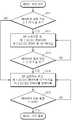
도 6은 본 발명의 일 실시예에 따른 연료 전지 시스템에서의 전력 관리 방법의 흐름도이다.
도 7은 도 6에 도시된 전력 관리 방법에 따른 연료 전지(10) 및 배터리(20)의 출력 전류의 파형을 도시한 도면이다.
도 8은 도 6에 도시된 61 단계의 배터리 모드의 상세 흐름도이다.
도 9는 도 5에 도시된 회로도에서 배터리(20)의 출력 전압이 3.7V 이상인 경우의 배터리 모드의 전류 흐름을 도시한 도면이다.
도 10은 도 5에 도시된 회로도에서 배터리(20)의 출력 전압이 3.7V 미만인 경우의 배터리 모드의 전류 흐름을 도시한 도면이다.
도 11은 도 6에 도시된 65 단계의 정상 모드의 상세 흐름도이다.
도 12는 도 5에 도시된 회로도에서 배터리(20)의 출력 전압이 3.7V 이상인 경우의 정상 모드의 전류 흐름을 도시한 도면이다.
도 13은 도 5에 도시된 회로도에서 배터리(20)의 출력 전압이 3.7V 미만인 경우의 배터리 모드의 전류 흐름을 도시한 도면이다.
도 14는 도 8, 11에 도시된 전력 관리 방법에 따른 연료 전지(10) 및 배터리(20)의 출력 전류의 파형을 도시한 도면이다.1 is a diagram illustrating charging characteristics of a lithium battery.
2-3 is a diagram showing charging characteristics of a lithium battery in a fuel cell system for performing constant current operation of the fuel cell.
4 is a configuration diagram of a fuel cell system according to an embodiment of the present invention.
FIG. 5 shows a detailed circuit diagram of the first DC /
6 is a flowchart of a power management method in a fuel cell system according to an embodiment of the present invention.
FIG. 7 illustrates waveforms of output currents of the
FIG. 8 is a detailed flowchart of the battery mode of
9 is a diagram illustrating the current flow in the battery mode when the output voltage of the
FIG. 10 is a diagram illustrating the current flow in the battery mode when the output voltage of the
FIG. 11 is a detailed flowchart of the normal mode of
FIG. 12 is a diagram illustrating a current flow in a normal mode when the output voltage of the
FIG. 13 is a diagram illustrating the current flow in the battery mode when the output voltage of the
FIG. 14 is a diagram illustrating waveforms of output currents of the
이하에서는 도면을 참조하여 본 발명의 실시예들을 상세히 설명한다. 본 실시예들은 연료 전지 시스템 및 연료 전지의 전력을 관리하는 방법에 관한 것으로서 이하의 실시예들의 특징을 보다 명확하게 설명하기 위하여 연료 전지를 구성하는 스택(stack), BOP(Balance Of Plants) 등, 이하의 실시예들이 속하는 기술 분야에서 통상의 지식을 가진 자에게 널리 알려져 있는 사항들에 관해서는 자세한 설명을 생략하기로 한다. 또한, 연료 전지로부터 출력되는 전류 및 전압은 보다 엄밀하게는 연료 전지의 스택으로부터 출력되는 전류 및 전압을 의미하나, 이하에서는 간단하게 연료 전지로부터 출력되는 전류 및 전압으로 기재하기로 한다.Hereinafter, with reference to the drawings will be described embodiments of the present invention; Embodiments of the present invention relate to a fuel cell system and a method for managing power of a fuel cell. In order to more clearly describe the features of the following embodiments, a stack, a balance of plants (BOP), etc. Detailed descriptions of matters well known to those skilled in the art will be omitted. In addition, the current and voltage output from the fuel cell more strictly mean the current and voltage output from the stack of the fuel cell, but hereinafter will be described simply as the current and voltage output from the fuel cell.
도 1은 리튬 배터리(lithium battery)의 충전 특성을 도시한 도면이다. 도 1에서 실선은 충전 전류를 나타내고, 점선은 충전 전압을 나타낸다. 리튬 배터리는 음극에 리튬을 사용한 2차 배터리를 가리키는 용어로서 이것의 예로는 리튬 이온 배터리(lithium ion battery), 리튬 폴리머 배터리(lithium polymer battery) 등을 들 수 있다. 이것은 높은 에너지 밀도를 갖고 있기 때문에 연료 전지의 보조 전원, 휴대폰의 전원 등으로 널리 사용되고 있다.1 is a diagram illustrating charging characteristics of a lithium battery. In FIG. 1, the solid line represents the charging current, and the dotted line represents the charging voltage. Lithium battery is a term for a secondary battery using lithium as a negative electrode, and examples thereof include a lithium ion battery, a lithium polymer battery, and the like. Since it has a high energy density, it is widely used as an auxiliary power supply of a fuel cell, a power supply of a mobile phone, etc.
도 1을 참조하면, 리튬 배터리의 충전 과정은 선충전 단계(precharge phase), 전류 통제 단계(current regulation phase), 및 전압 통제 단계(voltage regulation phase)로 분류된다. 선충전 단계에서는 선형 충전(linear charge) 방식이 사용되고, 전류 통제 단계 및 전압 통제 단계에서는 PWM(Pulse Width Modulation) 충전 방식이라는 고속 충전 방식이 사용된다. 일반적으로, 리튬 배터리의 충전 한계 전압은 4.2V이다. 리튬 배터리에 공급되는 충전 전원(charging power source)의 전압이 이 한계 값을 초과하면, 배터리 성능이 열화되게 된다. 따라서, 리튬 배터리의 충전 시에 이와 같은 충전 한계 전압이 고려되어야 한다.Referring to FIG. 1, the charging process of a lithium battery is classified into a precharge phase, a current regulation phase, and a voltage regulation phase. In the precharge phase, a linear charge method is used. In the current control step and the voltage control step, a fast charging method called a pulse width modulation (PWM) charging method is used. In general, the charge limit voltage of a lithium battery is 4.2V. If the voltage of the charging power source supplied to the lithium battery exceeds this limit, the battery performance will be degraded. Therefore, this charge limit voltage should be taken into account when charging a lithium battery.
선충전 단계에서는 리튬 배터리를 충전에 적응시키기 위하여 리튬 배터리에 공급되는 충전 전원의 전류 값과 전압 값을 Ishort 및 Vshort로 설정한다. 이 경우, 리튬 배터리의 전압 값은 Vshort까지 서서히 상승하게 된다. 전류 통제 단계에서는 리튬 배터리에 공급되는 충전 전원의 전류 값을 일정하게 유지시킨 상태에서 충전 전원의 전압 값을 충전 한계 전압 4.2V까지 상승시킨다. 여기에서의 일정 전류 값이 과도하게 높은 경우에도 리튬 배터리는 열화될 수 있기 때문에 리튬 배터리의 성능, 예를 들면 방전율(discharging rate) 등을 고려하여 한계 전류 값을 설정한다. 전압 통제 단계에서는 리튬 배터리에 공급되는 충전 전원의 전압 값을 충전 한계 전압 4.2V로 일정하게 유지시킨 상태에서 리튬 배터리의 충전 용량이 증가함에 따라 충전 전원의 전류 값을 서서히 감소시킨다.In the precharge step, the current value and the voltage value of the charging power supplied to the lithium battery are set to Ishort and Vshort to adapt the lithium battery to the charging. In this case, the voltage value of the lithium battery gradually rises to Vshort. In the current control step, the voltage value of the charging power source is increased to the charging limit voltage 4.2V while keeping the current value of the charging power supplied to the lithium battery constant. Since the lithium battery may deteriorate even when the constant current value is excessively high here, the limit current value is set in consideration of the performance of the lithium battery, for example, the discharging rate. In the voltage control step, the current value of the charging power is gradually decreased as the charging capacity of the lithium battery is increased while the voltage value of the charging power supplied to the lithium battery is kept constant at the charging limit voltage 4.2V.
도 2-3은 연료 전지의 정전류 운전을 하는 연료 전지 시스템에서의 리튬 배터리의 충전 특성을 도시한 도면이다. 일반적으로, 연료 전지 시스템은 연료 전지로부터 정전류(constant current)가 출력되도록 하기 위한 정전류 운전을 하거나, 정전압(constant voltage)이 출력되도록 하기 위한 정전압 운전을 한다. 연료 전지를 정전류 운전하는 경우에는 연료 전지로부터 출력되는 전압은 변동하게 되고, 연료 전지를 정전압 운전하는 경우에는 연료 전지로부터 출력되는 전류가 변동하게 된다. 특히, 도 2-3에 적용되는 연료 전지 시스템은 연료 전지가 부하의 주 전원으로서의 역할을 하고, 리튬 배터리는 연료 전지를 시동하거나 부하에 대한 보조 전원으로서 역할을 하는 구조를 갖는다. 이하에서는 도 2-3을 참조하면서 연료 전지의 정전류 운전을 하는 연료 전지 시스템의 문제점을 살펴보기로 한다.2-3 is a diagram showing charging characteristics of a lithium battery in a fuel cell system for performing constant current operation of the fuel cell. In general, a fuel cell system performs a constant current operation for outputting a constant current from the fuel cell, or a constant voltage operation for outputting a constant voltage. In the case of constant current operation of the fuel cell, the voltage output from the fuel cell fluctuates, and in the case of constant voltage operation of the fuel cell, the current output from the fuel cell fluctuates. In particular, the fuel cell system applied to FIGS. 2-3 has a structure in which a fuel cell serves as a main power source of a load, and a lithium battery starts a fuel cell or serves as an auxiliary power source for a load. Hereinafter, a problem of the fuel cell system for performing constant current operation of the fuel cell will be described with reference to FIGS. 2-3.
도 1에 도시된 전류 통제 단계까지의 충전 용량은 일반적으로 리튬 배터리의 최대 충전 용량의 80%이다. 도 2는 리튬 배터리의 충전 용량이 80% 미만인 경우이다. 이 경우, 리튬 배터리의 충전은 도 1에 도시된 전류 통제 단계에서 이루어지기 때문에 리튬 배터리에 공급되는 충전 전원의 전류 값이 일정하게 유지되면서 충전 전원의 전압 값이 4.2 V까지 상승하게 된다. 도 2를 참조하면, 부하의 소비 전력의 변동에 따라 부하에 공급되는 전류가 일정하다가 감소된다. 부하에 공급되는 전류가 일정하면, 연료 전지 및 리튬 배터리로부터 동시에 부하 측으로 정전류가 공급된다. 부하에 공급되는 전류가 감소되면, 연료 전지 시스템이 정전류 운전을 하고 있기 때문에 연료 전지로부터 부하 측으로 정전류 Itarget이 공급되나, 리튬 배터리로부터 부하에 공급되는 전류는 감소하게 된다. 특히, 연료 전지로부터 출력되는 정전류 Itarget 미만으로 부하에 공급되는 전류가 감소되면, 연료 전지의 잉여 전력은 리튬 배터리의 충전에 사용된다.The charge capacity up to the current control stage shown in FIG. 1 is generally 80% of the maximum charge capacity of a lithium battery. 2 is a case where the charge capacity of the lithium battery is less than 80%. In this case, since the charging of the lithium battery is performed in the current control step shown in FIG. 1, the voltage value of the charging power is increased to 4.2 V while the current value of the charging power supplied to the lithium battery is kept constant. Referring to FIG. 2, the current supplied to the load is constant and then reduced according to a change in power consumption of the load. If the current supplied to the load is constant, a constant current is supplied to the load side simultaneously from the fuel cell and the lithium battery. When the current supplied to the load decreases, the constant current Itarget is supplied from the fuel cell to the load side because the fuel cell system is in constant current operation, but the current supplied to the load from the lithium battery decreases. In particular, when the current supplied to the load is reduced below the constant current Itarget output from the fuel cell, the surplus power of the fuel cell is used for charging the lithium battery.
도 3은 리튬 배터리의 충전 용량이 80% 이상인 경우이다. 이 경우, 리튬 배터리의 충전은 도 1에 도시된 전압 통제 단계에서 이루어지기 때문에 리튬 배터리에 공급되는 충전 전원의 전압 값이 4.2V로 유지되면서 충전 전원의 전류 값이 서서히 감소하게 된다. 도 3을 참조하면, 부하의 소비 전력의 변동에 따라 부하에 공급되는 전류가 일정하다가 감소된다. 부하에 공급되는 전류가 일정하면, 연료 전지 및 리튬 배터리로부터 동시에 부하 측으로 정전류가 공급된다. 부하에 공급되는 전류가 감소되면, 연료 전지 시스템이 정전류 운전을 하고 있기 때문에 연료 전지로부터 부하 측으로 정전류 Itarget이 공급되나, 리튬 배터리로부터 부하에 공급되는 전류는 감소하게 된다. 한편, 연료 전지로부터 출력되는 정전류 Itarget 미만으로 부하에 공급되는 전류가 감소되는 경우에 리튬 배터리의 충전이 이루어지지 않는다. 리튬 배터리의 충전 용량이 80% 이상인 경우에는 충전 전압 값이 4.2V의 고전압으로 일정하게 유지되어야 하는데 연료 전지 시스템이 정전류 운전을 하고 있어 연료 전지로부터 일정한 전압 값을 인출할 수 없기 때문이다. 만약, 리튬 배터리의 충전을 위해서 연료 전지를 정전압 운전을 한다면, 연료 전지 시스템은 원래의 정전류 운전 기능을 잃게 되고, 연료 전지의 고전압 운전이 되어 연료 전지의 내구성에 문제가 발생할 수 있다.3 is a case where the charge capacity of the lithium battery is 80% or more. In this case, since the charging of the lithium battery is performed in the voltage control step shown in FIG. 1, the current value of the charging power is gradually decreased while the voltage value of the charging power supplied to the lithium battery is maintained at 4.2V. Referring to FIG. 3, the current supplied to the load is constant and then reduced according to a change in power consumption of the load. If the current supplied to the load is constant, a constant current is supplied to the load side simultaneously from the fuel cell and the lithium battery. When the current supplied to the load decreases, the constant current Itarget is supplied from the fuel cell to the load side because the fuel cell system is in constant current operation, but the current supplied to the load from the lithium battery decreases. On the other hand, when the current supplied to the load decreases below the constant current Itarget output from the fuel cell, the lithium battery is not charged. If the charge capacity of the lithium battery is more than 80%, the charge voltage value should be kept constant at a high voltage of 4.2V because the fuel cell system is in constant current operation and thus cannot draw a constant voltage value from the fuel cell. If the fuel cell is operated at constant voltage to charge the lithium battery, the fuel cell system loses its original constant current driving function, and the fuel cell is subjected to high voltage operation, which may cause a problem in the durability of the fuel cell.
도 4는 본 발명의 일 실시예에 따른 연료 전지 시스템의 구성도이다. 도 4를 참조하면, 본 실시예에 따른 연료 전지 시스템은 연료 전지(10), 배터리(20), FC 측정부(31), BAT 측정부(32), 부하 측정부(33), 제 1 DC/DC 컨버터(41), 제 2 DC/DC 컨버터(42), BP 스위치(51), BT 스위치(52), BOP(61), BOP 운전부(62), 및 제어부(70)로 구성된다. 특히, 도 4에 도시된 연료 전지 시스템은 배터리(20)의 사용에 의한 배터리(20)의 성능 변화에 따라 연료 전지(10)와 배터리(20) 중 적어도 하나의 출력 전력을 부하(80)에 공급하는 하이브리드(hybrid) 구조를 갖는다.4 is a configuration diagram of a fuel cell system according to an embodiment of the present invention. Referring to FIG. 4, the fuel cell system according to the present embodiment includes a
연료 전지(10)는 연료가 가지고 있는 화학 에너지를 전기 화학적 반응 (electrochemical reaction)을 이용하여 직접 전기 에너지로 변환함으로써 DC(Direct Current) 전력을 생산하는 발전 장치이다. 이와 같은 연료 전지의 예로는 고체 산화물 연료 전지(SOFC, Solid Oxide Fuel Cell), 고분자 전해질 연료 전지(PEMFC, Polymer Electrolyte Membrane Fuel Cell), 직접 메탄올 연료 전지(DMFC, Direct Methanol Fuel Cell) 등을 들 수 있다.The
배터리(20)는 연료 전지(10)의 시동을 위한 전원(power source)으로서의 역할을 하거나, 연료 전지(10)와 함께 부하(80)에 대한 전원으로서의 역할을 한다. 본 발명의 실시예들에 사용되는 배터리(20)는 일반적으로 리튬 배터리가 될 수 있으나, 충전이 가능한 대용량 커패시터(capacitor) 등도 될 수 있다. 이와 같이, 배터리가 장착된 연료 전지 시스템은 독립적으로 전력 생산이 가능하기 때문에 휴대용 연료 전지 시스템으로 사용된다. 휴대용 연료 전지 시스템의 연료 전지로는 다른 종류의 연료 전지에 비해 그 크기가 작은 DMFC가 주로 사용된다.The
FC 측정부(31)는 연료 전지(10)의 출력 상태를 측정한다. 예를 들어, FC 측정부(31)는 연료 전지(10)의 출력 전류의 값과 출력 전압의 값을 측정한다. 본 실시예에서, 연료 전지(10)의 전류 값 또는 전압 값이란 보다 엄밀하게는 연료 전지(10)의 스택의 양극(anode)과 음극(cathode) 간의 전류 값 또는 전압 값을 의미한다. BAT 측정부(32)는 배터리(20)의 출력 상태를 측정한다. 예를 들어, BAT 측정부(32)는 배터리(20)의 출력 전류의 값과 출력 전압의 값을 측정한다. 부하 측정부(33)는 부하(80)의 입력 상태를 측정한다. 예를 들어, 부하 측정부(33)는 부하(80)의 입력 전류의 값과 입력 전압의 값을 측정한다. 도 4에 도시된 실시예에 따르면, 제 2 DC/DC 컨버터(42)의 동작을 결정하기 위하여 배터리(20)의 출력 전압이 참조된다. 배터리(20)의 출력 전압은 BAT 측정부(32)에 의해 측정된 전압 값을 의미한다. 부하(80)에서 요구하는 전압을 보다 정밀하게 맞추기 위하여 부하 측정부(33)에 의해 측정된 부하(80)의 입력 전압을 참조하여 제 2 DC/DC 컨버터(42)의 동작을 결정할 수도 있다.The
제 1 DC/DC 컨버터(41)는 연료 전지(10)의 출력 전압을 제어부(70)의 제어에 따른 전압으로 변경한다. 특히, 제 1 DC/DC 컨버터(41)는 제어부(70)의 제어에 따라 연료 전지(10)로부터 정전류가 출력되도록 연료 전지(10)의 출력 전압을 변경한다. 연료 전지(10)의 상태나 부하(80)의 변동에 따라 연료 전지(10)로부터 출력되는 전력의 변동이 있는 경우에도 연료 전지(10)의 출력 전압을 변경함으로써 연료 전지(10)의 출력 전류를 일정하게 유지할 수 있다. 이와 같이, 제 1 DC/DC 컨버터(41)는 부하(80)가 변동되는 상태에서도 연료 전지(10)의 정전류 운전을 할 수 있기 때문에 연료 전지(10)로의 연료 공급이 일정하게 유지될 수 있고, 결국 연료 전지(10)의 수명이 연장될 수 있다.The first DC /
제 2 DC/DC 컨버터(42)는 제 1 DC/DC 컨버터(41)의 출력 전압과 배터리(20)의 출력 전압 중 적어도 하나를 제어부(70)의 제어에 따른 전압으로 변경한다. 특히, 제 2 DC/DC 컨버터(42)는 제 1 DC/DC 컨버터(41)의 출력 전압과 배터리(20)의 출력 전압 중 적어도 하나가 소정의 목표 전압(target voltage), 예를 들어 부하(80)에서 요구하는 전압과 매칭되지 않는 경우에 제어부(70)의 제어에 따라 제 1 DC/DC 컨버터(41)의 출력 전압과 배터리(20)의 출력 전압 중 적어도 하나를 소정의 목표 전압으로 변경한다. 이와 같이, 제 2 DC/DC 컨버터(42)는 부하(80)에 입력되는 전압을 일정 수준 이상으로 유지할 수 있기 때문에 부하(80)의 입력 전압이 안정화될 수 있다. 또한, 제 2 DC/DC 컨버터(42)의 출력 전력 중 부하(80)에 공급되고 남은 잉여 전력은 배터리(20)의 충전용으로 사용될 수도 있다. 이 경우, 제 1 DC/DC 컨버터(41)의 출력 전압이 배터리(20)의 충전 전압에 매칭되지 않은 경우에 제 2 DC/DC 컨버터(42)는 제 1 DC/DC 컨버터(41)의 출력 전압을 배터리(20)의 충전 전압으로 변경할 수도 있다.The second DC /
BP 스위치(51)는 배터리(20)의 성능의 변화를 고려하여 제 1 DC/DC 컨버터(41)와 배터리(20)로부터 출력된 전력을 제 2 DC/DC 컨버터(42)에 전달하지 않고 부하(80) 측으로 바이패스(bypass)하기 위하여, 제어부(70)의 제어에 따라 제 1 DC/DC 컨버터(41)와 배터리(20)의 출력단과 부하(80)의 직결(direct connection)을 스위칭한다. BT 스위치(52)는 배터리(20)의 출력단에 위치하여 제어부(70)의 제어에 따라 배터리(20)의 출력을 차단하거나 허용한다.The
BOP(61)는 연료 전지(10)를 구동시키기 위한 주변 기기들로서, 연료 전지(110)에 연료, 예를 들어 수소를 공급하는 펌프(pump), 이 연료를 산화시키기 위한 산화제, 예를 들어 공기, 산소 등을 공급하는 펌프, 냉각수(coolant)를 공급하는 펌프 등으로 구성된다. BOP(61)는 일반적으로 연료 전지(10)로부터 제공된 전력, 즉 제 1 DC/DC 컨버터(41)로부터 출력된 전력을 이용하여 구동되나, 연료 전지(10)의 전력 생산이 충분하지 않거나 제 1 DC/DC 컨버터(41)가 동작하지 않는 상태라면 배터리(20)로부터 출력된 전력을 이용하여 구동된다. BOP 운전부(62)는 제어부(70)의 제어에 따라 BOP(61)를 운전(drive)한다. 즉, BOP 운전부(62)는 제어부(70)의 제어에 따라 상기된 펌프들을 구동함으로써 연료 전지(10)에 연료, 공기, 냉각수 등을 공급한다. 이것에 의해 연료 전지(10)의 전력 생산이 가능하게 된다.The
제어부(70)는 BAT 측정부(32)에 의해 측정된 배터리(20)의 출력 상태, 즉 배터리(20)의 출력 전류 값과 출력 전압 값 중 적어도 하나를 이용하여 배터리(20)의 현재 성능을 결정하고, 배터리(20)의 성능의 변화에 따라 제 1 DC/DC 컨버터(41)와 제 2 DC/DC 컨버터(42) 각각의 동작을 제어하고, BP 스위치(51)의 온/오프(on/off)를 제어한다. 예를 들어, 제어부(70)는 BAT 측정부(32)에 의해 측정된 배터리(20)의 출력 전류 값과 출력 전압 값 중 적어도 하나를 이용하여 배터리(20)의 잔존 용량(SOC, State Of Charge)을 계산하고, 배터리(20)의 잔존 용량의 변화에 따라 제 1 DC/DC 컨버터(41)와 제 2 DC/DC 컨버터(42) 각각의 동작과 BP 스위치(51)의 온/오프를 제어할 수 있다. 이것은 배터리(20)의 사용에 의한 배터리(20)의 잔존 용량 변화에 따라 연료 전지(10)의 전력과 배터리(20)의 전력을 적절하게 부하(80) 측에 분배하기 위한 것이다.The
배터리(20)의 잔존 용량을 이용하는 실시예와는 다른 실시예로서, 제어부(70)는 배터리(20)의 출력 전압의 변화에 따라 제 1 DC/DC 컨버터(41)와 제 2 DC/DC 컨버터(42) 각각의 동작을 제어할 수도 있다. 아니면, 제어부(70)는 배터리(20)의 잔존 용량의 변화와 배터리(20)의 출력 전압의 변화를 함께 고려하여 제 1 DC/DC 컨버터(41)와 제 2 DC/DC 컨버터(42) 각각의 동작을 제어할 수도 있다. 이상의 실시예들이 속하는 기술 분야에서 통상의 지식을 가진 자라면, 배터리(20)의 잔존 용량과 배터리(20)의 출력 전압 외에 다른 파라미터들이 배터리(20)의 성능을 나타내는데 사용될 수 있음을 이해할 수 있다.As an embodiment different from the embodiment using the remaining capacity of the
배터리(20)의 잔존 용량의 측정법에는 화학 측정법(chemical method), 전압 측정법(voltage method), 전류 적분법(current integration method), 압력 측정법(pressure method) 등이 있다. 도 4에 도시된 연료 전지 시스템에서는 전압 측정법 내지 전류 적분법을 이용한다. 전압 측정법은 배터리(20)의 현재 출력 전압을 측정하고, 이것을 배터리(20)의 방전 곡선(discharge curve)과 대조하여 잔존 용량을 계산하는 방법이다. 전류 적분법은 배터리(20)의 출력 전류를 전체 사용 시간에 걸쳐 측정하고 적분함으로써 잔존 용량을 계산하는 방법이다.As a method of measuring the remaining capacity of the
보다 상세하게 설명하면, 제어부(70)는 배터리(20)의 현재 성능이 소정 수준 이상이면, 예를 들어 배터리(20)의 잔존 용량이 50%이상이면, 제 1 DC/DC 컨버터를 디스에이블(disable)시키고, BP 스위치(51)를 온(on)시킴으로써 배터리(20)의 출력 전력만을 부하(80)에 공급한다. 또한, 제어부(70)는 배터리의 현재 성능이 소정 수준 미만이면, 예를 들어 배터리(20)의 잔존 용량이 50%미만이면, 제 1 DC/DC 컨버터(41)를 인에이블(enable)시키고, BP 스위치(51)를 오프(off)시킴으로써 연료 전지(10)의 출력 전력과 배터리(20)의 출력 전력을 함께 부하(80)에 공급한다.In more detail, the
또한, 제어부(70)는 연료 전지(10)로부터 정전류가 출력되도록 제 1 DC/DC 컨버터(41)의 동작을 제어한다. 제 1 DC/DC 컨버터(41)로부터 출력된 전력은 제 1 DC/DC 컨버터(41)의 출력 전압과 배터리(20)의 출력 전압간의 전위차에 따라 부하(80) 및 배터리(20) 모두에 공급될 수도 있고, 부하(80)에만 공급될 수도 있다. 제 1 DC/DC 컨버터(41)로부터 배터리(20)로 출력된 전력은 배터리(20)의 충전에 사용된다. 다시 말하면, 제 1 DC/DC 컨버터(41)의 출력 전력 중 부하(80)에 공급되고 남은 잉여 전력은 배터리(20)의 충전용으로 사용된다.In addition, the
또한, 제어부(70)는 부하(80) 측에 소정 값 이상의 전압의 전력이 공급되도록 제 2 DC/DC 컨버터(42)의 동작을 제어한다. 보다 상세하게 설명하면, 제어부(70)는 배터리(20)의 출력 전압이 소정 값 미만이면, 예를 들어 배터리(20)의 출력 전압이 배터리(20)의 셀 수 X 3.7V 미만이면 제 2 DC/DC 컨버터(42)를 인에이블시키고, 제 2 DC/DC 컨버터(42)로부터 배터리(20)의 셀 수 X 3.7V 이상의 전압이 출력되도록 제 2 DC/DC 컨버터(42)의 동작을 제어한다.In addition, the
도 5는 도 4에 도시된 제 1 DC/DC 컨버터(41) 및 제 2 DC/DC 컨버터(42)의 상세 회로도를 도시한 도면이다. 도 5의 전체적인 복잡도를 낮추고, 제 1 DC/DC 컨버터(41) 및 제 2 DC/DC 컨버터(42)의 회로를 보다 상세하게 도시하기 위하여 제 1 DC/DC 컨버터(41) 및 제 2 DC/DC 컨버터(42) 외에 연료 전지(10), 배터리(20), BP 스위치(51), 및 부하(80)만을 함께 도시하였고, 그 외의 구성 요소들을 생략하였다. 특히, 도 5에 도시된 제 1 DC/DC 컨버터(41) 및 제 2 DC/DC 컨버터(42)의 트랜지스터들로는 그 내부에서의 전력 손실이 거의 없는 Power MOSFET(Metal Oxide Semiconductor Field Effect Transistor)가 사용되었다.FIG. 5 shows a detailed circuit diagram of the first DC /
도 5를 참조하면, 제 1 DC/DC 컨버터(41)는 트랜지스터 T13과 T14, 커패시터 C11, 인덕터(inductor) L11이 도 7에 도시된 형태로 배치된 벅(buck) 컨버터로 구현된다. 벅 컨버터는 트랜지스터 T13과 T14에 입력된 제어 신호의 스위칭 주파수에 비례하여 입력 전압을 하강시키는 컨버터로서 이것의 동작 원리는 도 5에 도시된 실시예가 속하는 기술 분야에서 통상의 지식을 가진 자에게는 주지된 사항이므로 이에 대한 자세한 설명을 생략하기로 한다. 커패시터 C11은 벅 컨버터로의 입력 전압을 안정화시키는 역할을 한다.Referring to FIG. 5, the first DC /
OP 앰프(operational amplifier) A12는 커패시터 C13을 이용하여 저항 R11과 R12에 의해 분배된 연료 전지(10)의 전압 값과 제어부(70)에 의해 결정된 목표 전압 값 V12의 차이를 적분함으로써 연료 전지(10)의 현재 전압 값이 제어부(70)에 의해 결정된 목표 전압 값보다 큰 구간이 계속되면 그 값의 크기가 상승하는 형태의 값을 출력한다. 또한, OP 앰프 A12는 연료 전지(10)의 현재 전압 값이 제어부(70)에 의해 결정된 목표 전압 값 V12보다 작은 구간이 계속되면 그 값의 크기가 하강하는 형태의 값을 출력한다. 여기에서, 목표 전압 값 V12는 연료 전지(10)의 전압 값을 변경시키는 것에 의하여 연료 전지(10)의 출력 전류를 일정하게 하기 위한 값이다. 제어부(70)는 FC 측정부(31)에 의해 측정된 연료 전지(10)의 출력 전류 값과 목표 정전류 값의 차이에 따라 목표 전압 값 V12를 조정한다.The operational amplifier A12 uses the capacitor C13 to integrate the
OP 앰프 A11은 저항 R13과 R14에 의해 분배된 벅 컨버터의 출력 전압 값과 기준 전압 V11과의 차이를 증폭한다. 기준 전압 V11은 OP 앰프 A11에 입력 가능한 전압 범위를 맞추기 위한 기준 전압이다. 제어부(70)는 OP 앰프 A11의 출력 전압에 따라 트랜지스터 T13과 T14를 스위칭한다. 이와 같이, 제어부(70)는 연료 전지(10)의 출력 전류 값에 따라 벅 컨버터의 출력 전압 값을 조정함으로써 제 1 DC/DC 컨버터(41)가 연료 전지(10)로부터 일정한 전류를 끌어내도록 할 수 있다.Op amp A11 amplifies the difference between the reference voltage V11 and the output voltage value of the buck converter divided by resistors R13 and R14. The reference voltage V11 is a reference voltage for adjusting the voltage range input to the OP amplifier A11. The
트랜지스터 T11과 T12는 벅 컨버터의 입력단에 위치하여 제어부(70)의 제어에 따라 벅 컨버터로의 전류 유입을 차단하거나 허용한다. 연료 전지(10) 측으로 전류가 역류하는 것을 방지하기 위하여 Power MOSFET 2개가 사용되었다. 제어부(70)는 벅 컨버터로의 전류 유입을 차단하거나 허용하는 트랜지스터 T11과 T12의 스위칭과 벅 컨버터의 트랜지스터 T13과 T14의 스위칭을 제어함으로써 제 1 DC/DC 컨버터(41)를 인에이블(enable)시키거나, 디스에이블(disable)시킬 수 있다.Transistors T11 and T12 are located at the input terminal of the buck converter to block or allow current flow into the buck converter under the control of the
도 5를 참조하면, 제 2 DC/DC 컨버터(42)는 트랜지스터 T22와 T23, 커패시터 C22, 인덕터(inductor) L21이 도 7에 도시된 형태로 배치된 부스트(boost) 컨버터로 구현된다. 부스트 컨버터는 트랜지스터 T22와 T23에 입력된 제어 신호의 스위칭 주파수에 비례하여 입력 전압을 상승시키는 컨버터로서 이것의 동작 원리는 도 7에 도시된 실시예가 속하는 기술 분야에서 통상의 지식을 가진 자에게는 주지된 사항이므로 이에 대한 자세한 설명을 생략하기로 한다. 커패시터 C21은 부스트 컨버터로의 입력 전압을 안정시키는 역할을 한다.Referring to FIG. 5, the second DC /
OP 앰프 A21은 저항 R21과 R22에 의해 분배된 부스트 컨버터의 출력 전압 값과 기준 전압 V22와의 차이를 증폭한다. 기준 전압 V22는 OP 앰프 A21에 입력 가능한 전압 범위를 맞추기 위한 기준 전압이다. 제어부(70)는 OP 앰프 A21의 출력 전압에 따라 트랜지스터 T22와 T23을 스위칭한다. 이와 같이, 제어부(70)는 부스트 컨버터의 출력 전압 값에 기초하여 제 2 DC/DC 컨버터(42)의 동작을 제어함으로써 제 2 DC/DC 컨버터(42)가 소정의 목표 전압, 예를 들어 부하(80)에서 요구하는 전압을 출력하도록 할 수 있다.The op amp A21 amplifies the difference between the reference voltage V22 and the output voltage value of the boost converter divided by resistors R21 and R22. The reference voltage V22 is a reference voltage for adjusting the voltage range input to the OP amplifier A21. The
트랜지스터 T21은 부스트 컨버터의 입력단에 위치하여 제어부(70)의 제어에 따라 부스트 컨버터로의 전류 유입을 차단하거나 허용한다. 제어부(70)는 부스트 컨버터로의 전류 유입을 차단하거나 허용하는 트랜지스터 T21의 스위칭과 부스트 컨버터의 트랜지스터 T22와 T23의 스위칭을 제어함으로써 제 2 DC/DC 컨버터(42)를 인에이블(enable)시키거나, 디스에이블(disable)시킬 수 있다. 제 2 DC/DC 컨버터(42)가 디스에이블되는 경우에 BP 스위치(51)에 해당하는 트랜지스터 T31과 T32는 온이 되어, 제 1 DC/DC 컨버터(41)와 배터리(20)의 출력단과 부하(80)는 직결되게 된다. 배터리(20) 측으로 전류가 역류하는 것을 방지하기 위하여 Power MOSFET 2개가 사용되었다.The transistor T21 is located at an input terminal of the boost converter to block or allow inflow of current into the boost converter under the control of the
도 6은 본 발명의 일 실시예에 따른 연료 전지 시스템에서의 전력 관리 방법의 흐름도이다. 도 6을 참조하면, 본 실시예에 따른 연료 전지 시스템에서의 전력 관리 방법은 도 4에 도시된 제어부(70)에서 시계열적으로 처리되는 단계들로 구성된다. 따라서, 이하 생략된 내용이라 하더라도 도 4에 도시된 연료 전지 시스템에 관하여 이상에서 기술된 내용은 본 실시예에 따른 연료 전지 시스템에서의 전력 관리 방법에도 적용된다. 특히, 도 6에 도시된 실시예는 배터리(20)의 잔존 용량의 변화에 따라 연료 전지(10)의 전력과 배터리(20)의 전력을 적절하게 부하(80) 측에 분배하기 위한 제어부(70)의 동작에 관한 것이다.6 is a flowchart of a power management method in a fuel cell system according to an embodiment of the present invention. Referring to FIG. 6, the power management method in the fuel cell system according to the present exemplary embodiment includes steps processed in time series by the
61 단계에서 제어부(70)는 연료 전지 시스템의 여러 동작 모드들 중 배터리(20)의 출력 전력만을 부하(80)에 공급하기 위한 배터리 모드(battery mode)에 따라 부하(80) 측으로의 연료 전지(10)와 배터리(20) 각각의 출력 전력의 공급과 BOP의 운전을 제어한다. 즉, 제어부(70)는 배터리 모드에 따라 배터리(20)의 출력 전력만을 부하(80)에 공급하기 위하여 제 1 DC/DC 컨버터(41)를 디스에이블시키고, BOP(61)가 구동되지 않도록 BOP 운전부(62)의 BOP 운전을 제어한다. 이와 같은 배터리 모드의 선택은 연료 전지 시스템의 운전을 시작할 때에 배터리(20)가 만충된 상태임을 가정한 것이다. 따라서, 연료 전지 시스템의 운전을 시작할 때에 배터리(20)의 충전 상태에 따라 배터리 모드가 아닌 다른 동작 모드가 선택될 수 있다.In
62 단계에서 제어부(70)는 61 단계의 배터리 모드에서의 배터리(20)의 방전 진행에 따라 배터리(20)의 잔존 용량이 소정의 하위 한계(low limit), 예를 들어 50% 미만이 되면, 연료 전지 시스템의 여러 동작 모드들 중 연료 전지(10)를 시동하기 위한 시동 모드(start-up mode)를 선택한다. 시동 모드가 선택되면 63 단계로 진행하고, 그렇지 않으면 61 단계로 돌아간다.In
63 단계에서 제어부(70)는 연료 전지 시스템의 동작 모드를 배터리 모드로부터 시동 모드로 전환하고, 시동 모드에 따라 부하(80) 측으로의 연료 전지(10)와 배터리(20) 각각의 출력 전력의 공급과 BOP의 운전을 제어한다. 즉, 제어부(70)는 시동 모드에 따라 연료 전지(10)를 시동하기 위하여, 제 1 DC/DC 컨버터(41)를 디스에이블시키고, BOP(61)의 구동을 시작하도록 BOP 운전부(62)의 BOP 운전을 제어한다. BOP 운전부(62)는 이와 같은 제어부(70)의 제어에 따라 연료 전지(10)에 연료, 공기, 냉각수 등을 공급하기 위한 펌프들의 구동을 시작한다.In
64 단계에서 제어부(70)는 FC 측정부(31)에 의해 측정된 연료 전지(10)의 전류 값 및 전압 값에 기초하여 연료 전지(10)가 부하(80)에서 요구하는 전력을 공급할 수 있는 안정 상태(stable state)에 도달하면, 연료 전지 시스템의 여러 동작 모드들 중 연료 전지(10)와 배터리(20)의 출력 전력을 동시에 부하(80)에 공급하기 위한 정상 모드(normal mode)를 선택한다. 정상 모드가 선택되면 65 단계로 진행하고, 그렇지 않으면 63 단계로 돌아간다. 연료 전지(10)는 전기 화학적 반응을 이용하여 전력을 생산하기 때문에 연료 전지(10)로부터 부하(80)에서 요구하는 전력을 끌어내기까지는 다소의 시간적 지체가 요구된다.In
65 단계에서 제어부(70)는 연료 전지 시스템의 동작 모드를 시동 모드로부터 정상 모드로 전환하고, 정상 모드에 따라 부하(80) 측으로의 연료 전지(10)와 배터리(20) 각각의 출력 전력의 공급과 BOP의 운전을 제어한다. 즉, 제어부(70)는 정상 모드에 따라 연료 전지(10)와 배터리(20)의 출력 전력을 동시에 부하(80)에 공급하기 위하여, 제 1 DC/DC 컨버터(41)를 인에이블시키고, BOP(61)가 구동하도록 BOP 운전부(62)의 BOP 운전을 제어한다. 제 1 DC/DC 컨버터(41)로부터 출력된 전력은 제 1 DC/DC 컨버터(41)의 출력 전압과 배터리(20)의 출력 전압간의 전위차에 따라 부하(80) 및 배터리(20) 모두에 공급될 수도 있고, 부하(80)에만 공급될 수도 있다. 제 1 DC/DC 컨버터(41)로부터 배터리(20)로 출력된 전력은 배터리(20)의 충전에 사용된다. 배터리(20)의 방전에 따라 배터리(20)의 출력 전압이 낮아지거나, 부하(80)의 변동에 따라 부하(80)의 소모 전력이 감소되면, 제 1 DC/DC 컨버터(41)의 출력 전압이 배터리(20)의 출력 전압보다 높아지게 된다. 이 경우, 제 1 DC/DC 컨버터(41)의 출력 전류는 배터리(20)로 흘러 들어가게 되어 배터리(20)의 충전이 이루어지게 된다. 배터리(20)의 충전에 사용된 전력은 연료 전지(10)의 발생 전력 중 부하(80)에 공급되고 남은 잉여 전력이다.In
66 단계에서 제어부(70)는 65 단계의 정상 모드에서의 배터리(20)의 충전 진행에 따라 배터리(20)의 잔존 용량이 소정의 상위 한계(high limit), 예를 들어 80% 보다 크게 되면, 연료 전지 시스템의 여러 동작 모드들 중 배터리(20)의 출력 전력만을 부하(80)에 공급하기 위한 배터리 모드를 선택한다. 배터리 모드가 선택되면 61 단계로 돌아가고, 그렇지 않으면 65 단계로 돌아간다.If the remaining capacity of the
도 7은 도 6에 도시된 전력 관리 방법에 따른 연료 전지(10) 및 배터리(20)의 출력 전류의 파형을 도시한 도면이다. 도 7을 참조하면, 정상 모드에서 연료 전지(10)로부터 전류가 출력됨에 따라 배터리(20)의 충전이 80%까지 진행됨을 알 수 있다. 또한, 배터리 모드 및 시동 모드에서 배터리(20)로부터 전류가 출력됨에 따라 배터리(20)의 방전이 50%까지 진행됨을 알 수 있다. 도 7에 도시된 전류 파형은 이상적인 전류 파형으로서 실제 전류 파형은 연료 전지(10) 및 배터리(20)의 출력 전류의 증감은 곡선의 형태로 나타날 수 있으며, 전류 파형 상에 리플(ripple)이 존재할 수 있다. 이와 같이, 배터리(20)의 잔존 용량의 변화에 따라 연료 전지(10)의 전력과 배터리(20)의 전력이 적절하게 부하(80) 측에 분배되는 하이브리드 구조를 통하여 연료 전지(10)의 구동 시간을 줄일 수 있기 때문에 고 연비의 연료 전지 시스템을 구현할 수 있다.FIG. 7 illustrates waveforms of output currents of the
도 8은 도 6에 도시된 61 단계의 배터리 모드의 상세 흐름도이다. 도 8을 참조하면, 도 6에 도시된 61 단계는 다음과 같은 단계들로 구성된다.FIG. 8 is a detailed flowchart of the battery mode of
611 단계에서 제어부(70)는 배터리(20)의 충전, 부하(80)의 변동 등에 의해 배터리(20)의 출력 전압이 소정의 목표 전압(target voltage), 예를 들어 배터리(20)의 셀(cell) 수 X 3.7V 이상이 되면, 612 단계로 진행하고, 그렇지 않으면 614 단계로 진행한다. 도 5에 도시된 배터리(20)의 셀 수는 4 개다. 이 경우, 배터리(20)의 출력 전압이 14.8V 이상이면, 612 단계로 진행하고, 그렇지 않으면 614 단계로 진행한다. 이것은 부하(80)에서 요구하는 최소 전압이 14.8V임을 가정한 것이다. 리튬 배터리의 한 셀의 공칭 전압(nominal voltage)은 3.7V이다. 부하(80)에 해당하는 휴대용 전자 기기 등은 이와 같은 공칭 전압을 고려하여 설계된다. 도 4에 도시된 부하(80)는 리튬 배터리의 4개의 셀을 기준으로 설계되었다고 가정한다.In
612 단계에서 제어부(70)는 BP 스위치(51)를 온하고, 제 1 DC/DC 컨버터(41)와 제 2 DC/DC 컨버터(42)를 디스에이블함으로써 연료 전지(10)의 출력 전력의 공급을 차단하고, 배터리(20)의 출력 전력만을 직접 부하(80)에 공급한다. 도 9는 도 5에 도시된 회로도에서 배터리(20)의 출력 전압이 3.7V 이상인 경우의 배터리 모드의 전류 흐름을 도시한 도면이다. 점선은 전류가 흐르지 않음을 나타내고, 실선은 전류가 흐름을 나타낸다. 도 9를 참조하면, BP 스위치(51)가 온이 되고 제 2 DC/DC 컨버터(42)가 디스에이블되어, 배터리(20)의 출력 전류가 제 2 DC/DC 컨버터(42)를 통과하지 않고, 부하(80)에 직접 전달됨을 알 수 있다.In
613 단계에서 제어부(70)는 배터리(20)의 방전, 부하(80)의 변동 등에 의해 배터리(20)의 출력 전압이 3.7V 미만이 되면 614 단계로 진행하고, 여전히 3.7V 이상을 유지하고 있으면 612 단계로 돌아간다.In
614 단계에서 제어부(70)는 BP 스위치(51)를 오프하고, 제 1 DC/DC 컨버터(41)를 디스에이블하고, 제 2 DC/DC 컨버터(42)를 인에이블함으로써 배터리(20)의 출력 전압을 소정의 목표 전압, 예를 들어 부하(80)에서 요구하는 전압으로 상승시키고, 이와 같이 상승된 전압의 전력만을 부하(80)에 공급한다. 도 10은 도 5에 도시된 회로도에서 배터리(20)의 출력 전압이 3.7V 미만인 경우의 배터리 모드의 전류 흐름을 도시한 도면이다. 점선은 전류가 흐르지 않음을 나타내고, 실선은 전류가 흐름을 나타낸다. 도 10을 참조하면, BP 스위치(51)가 오프가 되고 제 2 DC/DC 컨버터(42)가 인에이블되어, 배터리(20)의 출력 전류가 제 2 DC/DC 컨버터(42)로 입력되고, 제 2 DC/DC 컨버터(42)에 의해 상승된 전압의 전력이 부하(80)에 전달됨을 알 수 있다.In
615 단계에서 제어부(70)는 배터리(20)의 잔존 용량이 50% 미만이 되면, 배터리 모드를 종료하고, 연료 전지 시스템의 동작 모드를 배터리 모드로부터 시동 모드로 전환한다.In
도 11은 도 6에 도시된 65 단계의 정상 모드의 상세 흐름도이다. 도 10을 참조하면, 도 6에 도시된 65 단계는 다음과 같은 단계들로 구성된다.FIG. 11 is a detailed flowchart of the normal mode of
651 단계에서 제어부(70)는 배터리(20)의 충전, 부하(80)의 변동 등에 의해 배터리(20)의 출력 전압이 배터리(20)의 셀(cell) 수 X 3.7V 이상이 되면, 612 단계로 진행하고, 그렇지 않으면 654 단계로 진행한다. 도 5에 도시된 배터리(20)의 셀 수는 4 개다. 이 경우, 배터리(20)의 출력 전압이 14.8V 이상이면, 652 단계로 진행하고, 그렇지 않으면 654 단계로 돌아간다. 이것은 부하(80)에서 요구하는 최소 전압이 14.8V임을 가정한 것이다. 제어부(70)는 제 1 DC/DC 컨버터(41)로부터 배터리(20)의 셀(cell) 수 X 3.7V 이상의 전압을 갖는 정전류가 출력되도록 제 1 DC/DC 컨버터(41)를 제어함으로써 배터리(20)의 출력 전압이 배터리(20)의 셀(cell) 수 X 3.7V 미만인 경우에 배터리(20)의 충전이 이루어지도록 할 수 있다. 배터리(20)의 안정적인 충전을 위해서, 연료 전지(10)는 부하(80)의 변동에도 배터리(20)의 셀(cell) 수 X 3.7V 이상의 전압을 출력할 수 있는 스택(stack)을 갖고 있어야 하며, 제 1 DC/DC 컨버터(41)는 연료 전지(10)로부터 정전류가 출력되도록 이와 같은 스택의 전압을 하강시키는 벅 컨버터의 형태로 설계된다.In
652 단계에서 제어부(70)는 BP 스위치(51)를 온하고, 제 1 DC/DC 컨버터(41)를 인에이블하고, 제 2 DC/DC 컨버터(42)를 디스에이블함으로써 연료 전지(10)의 출력 전력과 배터리(20)의 출력 전력을 동시에 직접 부하(80)에 공급한다. 도 12는 도 5에 도시된 회로도에서 배터리(20)의 출력 전압이 3.7V 이상인 경우의 정상 모드의 전류 흐름을 도시한 도면이다. 점선은 전류가 흐르지 않음을 나타내고, 실선은 전류가 흐름을 나타낸다. 도 12를 참조하면, BP 스위치(51)가 온이 되고 제 2 DC/DC 컨버터(42)가 디스에이블되어, 배터리(20)의 출력 전류가 제 2 DC/DC 컨버터(42)를 통과하지 않고, 부하(80)에 직접 전달됨을 알 수 있다.In
653 단계에서 제어부(70)는 부하(80)의 변동, 배터리(20)의 방전 등에 의해 배터리(20)의 출력 전압이 3.7V 미만이 되면 614 단계로 진행하고, 여전히 3.7V 이상을 유지하고 있으면 612 단계로 돌아간다.In
654 단계에서 제어부(70)는 BP 스위치(51)를 오프하고, 제 1 DC/DC 컨버터(41)와 제 2 DC/DC 컨버터(42)를 인에이블함으로써 제 1 DC/DC 컨버터(41)의 출력 전압과 배터리(20)의 출력 전압을 소정의 목표 전압(target voltage), 예를 들어 부하(80)에서 요구하는 전압으로 상승시키고, 이와 같이 상승된 전압의 전력을 부하(80)에 공급한다. 도 13은 도 5에 도시된 회로도에서 배터리(20)의 출력 전압이 3.7V 미만인 경우의 배터리 모드의 전류 흐름을 도시한 도면이다. 점선은 전류가 흐르지 않음을 나타내고, 실선은 전류가 흐름을 나타낸다. 도 13을 참조하면, BP 스위치(51)가 오프가 되고 제 2 DC/DC 컨버터(42)가 인에이블되어, 제 1 DC/DC 컨버터(41)의 출력 전류와 배터리(20)의 출력 전류가 제 2 DC/DC 컨버터(42)로 입력되고, 제 2 DC/DC 컨버터(42)에 의해 상승된 전압의 전력이 부하(80)에 전달됨을 알 수 있다.In
655 단계에서 제어부(70)는 배터리(20)의 잔존 용량이 80% 미만이 되면, 정상 모드를 종료하고, 연료 전지 시스템의 동작 모드를 정상 모드로부터 배터리 모드로 전환한다.In
도 14는 도 8, 11에 도시된 전력 관리 방법에 따른 연료 전지(10) 및 배터리(20)의 출력 전류의 파형을 도시한 도면이다. 도 14를 참조하면, 정상 모드에서 연료 전지(10)로부터 전류가 출력됨에 따라 배터리(20)의 충전이 80%까지 진행됨을 알 수 있다. 또한, 배터리 모드 및 시동 모드에서 배터리(20)로부터 전류가 출력됨에 따라 배터리(20)의 방전이 50%까지 진행됨을 알 수 있다. 특히, 도 14에서 배터리(20)의 출력 전압이 3.7V 이상인 구간에서는 제 2 DC/DC 컨버터(42)가 디스에이블되고, 배터리(20)의 출력 전압이 3.7V 미만인 구간에서는 제 2 DC/DC 컨버터(42)가 인에이블된다. 도 7에 도시된 전류 파형은 이상적인 전류 파형으로서 실제 전류 파형은 연료 전지(10) 및 배터리(20)의 출력 전류의 증감은 곡선의 형태로 나타날 수 있으며, 전류 파형 상에 리플(ripple)이 존재할 수 있다. 이와 같이, 배터리(20)의 출력 전압에 따라 제 2 DC/DC 컨버터(42)가 인에이블/디스에이블되기 때문에 부하(80)의 입력 전압을 안정화시킴과 동시에 제 2 DC/DC 컨버터(42)의 전력 손실을 줄일 수 있어 출력 전압이 안정화된 고 효율의 연료 전지 시스템을 구현할 수 있다.FIG. 14 is a diagram illustrating waveforms of output currents of the
상기된 바와 같이 실시예들에 따르면, 연료 전지(10)의 정전류 운전을 하면서 연료 전지 시스템의 출력 전압을 안정화시킬 수 있는 고 연비와 고 효율의 연료 전지 시스템을 구현할 수 있다.According to the embodiments as described above, it is possible to implement a fuel cell system of high fuel efficiency and high efficiency capable of stabilizing the output voltage of the fuel cell system while the constant current operation of the
한편, 상기된 바와 같이, 제어부(70)에 의해 실행되는 전력 관리 방법은 컴퓨터에서 실행될 수 있는 프로그램으로 작성 가능하고, 컴퓨터로 읽을 수 있는 기록매체를 이용하여 상기 프로그램을 동작시키는 범용 디지털 컴퓨터에서 구현될 수 있다. 상기 컴퓨터로 읽을 수 있는 기록매체는 마그네틱 저장매체(예를 들면, 롬, 플로피 디스크, 하드 디스크 등), 광학적 판독 매체(예를 들면, 시디롬, 디브이디 등)와 같은 저장매체를 포함한다.On the other hand, as described above, the power management method executed by the
이제까지 본 발명에 대하여 그 바람직한 실시예들을 중심으로 살펴보았다. 본 발명이 속하는 기술 분야에서 통상의 지식을 가진 자는 본 발명이 본 발명의 본질적인 특성에서 벗어나지 않는 범위에서 변형된 형태로 구현될 수 있음을 이해할 수 있을 것이다. 그러므로 개시된 실시예들은 한정적인 관점이 아니라 설명적인 관점에서 고려되어야 한다. 본 발명의 범위는 전술한 설명이 아니라 특허청구범위에 나타나 있으며, 그와 동등한 범위 내에 있는 모든 차이점은 본 발명에 포함된 것으로 해석되어야 할 것이다.So far I looked at the center of the preferred embodiment for the present invention. Those skilled in the art will appreciate that the present invention can be implemented in a modified form without departing from the essential features of the present invention. Therefore, the disclosed embodiments should be considered in an illustrative rather than a restrictive sense. The scope of the present invention is shown in the claims rather than the foregoing description, and all differences within the scope will be construed as being included in the present invention.
10 ... 연료 전지
20 ... 배터리
31 ... FC 측정부
32 ... BAT 측정부
33 ... 부하 측정부
41 ... 제 1 DC/DC 컨버터
42 ... 제 2 DC/DC 컨버터
51 ... BP 스위치
52 ... BT 스위치
61 ... BOP
62 ... BOP 운전부
70 ... 제어부
80 ... 부하10 ... fuel cell
20 ... battery
31 ... FC measuring unit
32 ... BAT measuring section
33 ... load measurement
41 ... first DC / DC converter
42 ... 2nd DC / DC Converter
51 ... BP switch
52 ... BT switch
61 ... BOP
62 ... BOP operation
70 ... Controls
80 ... load
Claims (16)
Translated fromKorean상기 연료 전지의 출력 전압을 변경하는 제 1 컨버터;
상기 제 1 컨버터의 출력 전압과 상기 배터리의 출력 전압을 변경하는 제 2 컨버터; 및
상기 배터리의 사용에 의한 상기 배터리의 성능 변화에 따라 상기 제 1 컨버터와 상기 제 2 컨버터 각각의 동작을 제어하는 제어부를 포함하는 연료 전지 시스템.A fuel cell system for supplying output power of at least one of a fuel cell and a battery to a load, the fuel cell system comprising:
A first converter for changing an output voltage of the fuel cell;
A second converter for changing an output voltage of the first converter and an output voltage of the battery; And
And a controller configured to control an operation of each of the first converter and the second converter according to a change in performance of the battery due to the use of the battery.
상기 배터리의 성능 변화는 상기 배터리의 잔존 용량의 변화와 상기 배터리의 출력 전압의 변화 중 적어도 하나를 포함하는 연료 전지 시스템.The method of claim 1,
The change in performance of the battery comprises at least one of a change in the remaining capacity of the battery and a change in the output voltage of the battery.
상기 제어부는 상기 연료 전지로부터 정전류가 출력되도록 상기 제 1 컨버터의 동작을 제어하는 연료 전지 시스템.The method of claim 1,
The control unit controls the operation of the first converter to output a constant current from the fuel cell.
상기 제어부는 상기 부하 측에 소정 값 이상의 전압의 전력이 공급되도록 상기 제 2 컨버터의 동작을 제어하는 연료 전지 시스템.The method of claim 1,
The control unit controls the operation of the second converter to supply power of a voltage equal to or greater than a predetermined value to the load side.
상기 배터리와 상기 부하의 직결(direct connection)을 스위칭하는 스위치를 더 포함하고,
상기 제어부는 상기 배터리의 성능 변화에 따라 상기 제 1 컨버터, 상기 제 2 컨버터 각각의 동작을 제어하고, 상기 스위치의 온/오프(on/off)를 제어하는 연료 전지 시스템.The method of claim 1,
Further comprising a switch for switching a direct connection of the battery and the load,
The control unit controls the operation of each of the first converter and the second converter in accordance with the change of the performance of the battery, and controls the on / off (on / off) of the switch.
상기 제어부는 상기 배터리의 현재 성능이 소정 수준 이상이면, 상기 제 1 컨버터를 디스에이블(disable)시키고, 상기 스위치를 온시킴으로써 상기 배터리의 출력 전력을 상기 부하에 공급하는 연료 전지 시스템.The method of claim 5, wherein
And the controller is configured to disable the first converter when the current performance of the battery is greater than or equal to a predetermined level, and supply the output power of the battery to the load by turning on the switch.
상기 제어부는 상기 배터리의 현재 성능이 소정 수준 미만이면, 상기 제 1 컨버터를 인에이블(enable)시키고, 상기 스위치를 오프시킴으로써 상기 연료 전지의 출력 전력과 상기 배터리의 출력 전력을 상기 부하에 공급하는 연료 전지 시스템.The method of claim 5, wherein
The controller is configured to enable the first converter when the current performance of the battery is less than a predetermined level, and to turn off the switch to supply fuel to the output power of the fuel cell and the output power of the battery to the load. Battery system.
상기 제어부는 상기 배터리의 출력 전압이 소정 값 미만이면, 상기 제 2 컨버터를 인에이블시키고, 상기 제 2 컨버터로부터 상기 소정 값 이상의 전압이 출력되도록 상기 제 2 컨버터의 동작을 제어하는 연료 전지 시스템.The method of claim 5, wherein
And the controller enables the second converter when the output voltage of the battery is less than a predetermined value and controls the operation of the second converter to output a voltage equal to or greater than the predetermined value from the second converter.
상기 배터리의 사용에 의한 상기 배터리의 성능 변화에 기초하여 상기 연료 전지 시스템의 여러 동작 모드들 중 어느 하나를 선택하는 단계; 및
상기 선택된 동작 모드에 따라 상기 부하 측으로의 상기 연료 전지와 상기 배터리 각각의 출력 전력의 공급을 제어하는 단계를 포함하는 전력 관리 방법.A power management method in a fuel cell system for supplying output power of at least one of a fuel cell and a battery, the method comprising:
Selecting one of several operating modes of the fuel cell system based on a change in performance of the battery by use of the battery; And
Controlling the supply of output power of each of said fuel cell and said battery to said load side in accordance with said selected mode of operation.
상기 배터리의 성능 변화는 상기 배터리의 잔존 용량의 변화와 상기 배터리의 출력 전압의 변화 중 적어도 하나를 포함하는 전력 관리 방법.The method of claim 9,
The change in performance of the battery includes at least one of a change in the remaining capacity of the battery and a change in the output voltage of the battery.
상기 선택하는 단계는 상기 배터리의 현재 성능이 소정 수준 이상이면, 상기 배터리의 출력 전력만을 상기 부하에 공급하기 위한 배터리 모드를 선택하고,
상기 제어하는 단계는 상기 배터리 모드에 따라 상기 연료 전지의 출력 전력의 공급을 차단하고, 상기 배터리의 출력 전력을 상기 부하에 공급하는 전력 관리 방법.The method of claim 9,
The selecting may include selecting a battery mode for supplying only the output power of the battery to the load when the current performance of the battery is greater than or equal to a predetermined level,
The controlling may include discontinuing supply of output power of the fuel cell according to the battery mode, and supplying output power of the battery to the load.
상기 제어하는 단계는 상기 배터리의 출력 전압이 소정 값보다 작으면, 상기 배터리의 출력 전압을 상승시키고, 상기 상승된 전압의 전력을 공급하는 전력 관리 방법.The method of claim 11,
The controlling may include increasing the output voltage of the battery and supplying power of the increased voltage when the output voltage of the battery is smaller than a predetermined value.
상기 배터리의 현재 성능이 상기 소정 수준 미만이면, 상기 배터리 모드로부터 상기 연료 전지를 시동하기 위한 시동 모드로 전환하는 단계; 및
상기 시동 모드에 따라 상기 연료 전지의 시동을 위해 상기 배터리의 출력 전력 중 일부를 공급하는 단계를 더 포함하는 전력 관리 방법.The method of claim 11,
If the current performance of the battery is less than the predetermined level, switching from the battery mode to a start mode for starting the fuel cell; And
Supplying some of the output power of the battery for starting the fuel cell in accordance with the start mode.
상기 연료 전지의 출력 상태가 안정되면, 상기 시동 모드로부터 상기 연료 전지의 출력 전력과 상기 배터리의 출력 전력을 동시에 상기 부하에 공급하기 위한 정상 모드로 전환하고,
상기 정상 모드에 따라 상기 연료 전지의 출력 전력과 상기 배터리의 출력 전력을 동시에 상기 부하에 공급하는 전력 관리 방법.The method of claim 13,
When the output state of the fuel cell is stabilized, switching from the start mode to the normal mode for simultaneously supplying the output power of the fuel cell and the output power of the battery to the load,
And a power management method of simultaneously supplying the output power of the fuel cell and the output power of the battery to the load according to the normal mode.
상기 제어하는 단계는 상기 배터리의 출력 전압이 소정 값 미만이면, 상기 배터리의 출력 전압을 상승시키고, 상기 상승된 전압의 전력을 공급하는 전력 관리 방법.The method of claim 14,
The controlling may include increasing the output voltage of the battery and supplying power of the increased voltage when the output voltage of the battery is less than a predetermined value.
Priority Applications (2)
| Application Number | Priority Date | Filing Date | Title |
|---|---|---|---|
| KR1020100069165AKR20120008353A (en) | 2010-07-16 | 2010-07-16 | Fuel cell system and power management method thereof |
| US13/137,013US20120013196A1 (en) | 2010-07-16 | 2011-07-15 | Fuel cell system and power managing method of the same |
Applications Claiming Priority (1)
| Application Number | Priority Date | Filing Date | Title |
|---|---|---|---|
| KR1020100069165AKR20120008353A (en) | 2010-07-16 | 2010-07-16 | Fuel cell system and power management method thereof |
Publications (1)
| Publication Number | Publication Date |
|---|---|
| KR20120008353Atrue KR20120008353A (en) | 2012-01-30 |
Family
ID=45466393
Family Applications (1)
| Application Number | Title | Priority Date | Filing Date |
|---|---|---|---|
| KR1020100069165AWithdrawnKR20120008353A (en) | 2010-07-16 | 2010-07-16 | Fuel cell system and power management method thereof |
Country Status (2)
| Country | Link |
|---|---|
| US (1) | US20120013196A1 (en) |
| KR (1) | KR20120008353A (en) |
Cited By (9)
| Publication number | Priority date | Publication date | Assignee | Title |
|---|---|---|---|---|
| KR101404403B1 (en)* | 2012-09-17 | 2014-06-10 | 한국에너지기술연구원 | Method for managing fule cell vehicle system |
| KR101480991B1 (en)* | 2012-08-31 | 2015-01-09 | 엘아이지넥스원 주식회사 | System for controlling hybrid fuel cell and method thereof |
| KR101510220B1 (en)* | 2013-08-06 | 2015-04-08 | 한국기계연구원 | A power supply for radio control object |
| US9093677B2 (en) | 2012-09-17 | 2015-07-28 | Korea Institute Of Energy Research | Apparatus and method for managing stationary fuel cell system |
| US9577274B2 (en) | 2012-09-17 | 2017-02-21 | Korea Institute Of Energy Research | Apparatus and method for managing fuel cell vehicle system |
| KR101897164B1 (en)* | 2017-03-06 | 2018-09-10 | 한국해양대학교 산학협력단 | System for controlling electric power of fuel cell for ship and method thereof |
| KR20190131720A (en) | 2018-05-17 | 2019-11-27 | 한국기계연구원 | Hybrid power supply apparatus of aerial vehicle |
| KR20210062113A (en) | 2019-11-20 | 2021-05-31 | 한국재료연구원 | Hybrid power supply apparatus of aerial vehicle |
| KR20230060991A (en)* | 2021-10-28 | 2023-05-08 | 현대모비스 주식회사 | Fuel cell system and power control method thereof |
Families Citing this family (212)
| Publication number | Priority date | Publication date | Assignee | Title |
|---|---|---|---|---|
| US9938186B2 (en) | 2012-04-13 | 2018-04-10 | Corning Incorporated | Strengthened glass articles having etched features and methods of forming the same |
| US10291066B1 (en) | 2014-05-07 | 2019-05-14 | Energous Corporation | Power transmission control systems and methods |
| US10256657B2 (en) | 2015-12-24 | 2019-04-09 | Energous Corporation | Antenna having coaxial structure for near field wireless power charging |
| US9368020B1 (en) | 2013-05-10 | 2016-06-14 | Energous Corporation | Off-premises alert system and method for wireless power receivers in a wireless power network |
| US9882427B2 (en) | 2013-05-10 | 2018-01-30 | Energous Corporation | Wireless power delivery using a base station to control operations of a plurality of wireless power transmitters |
| US10218227B2 (en) | 2014-05-07 | 2019-02-26 | Energous Corporation | Compact PIFA antenna |
| US10224982B1 (en) | 2013-07-11 | 2019-03-05 | Energous Corporation | Wireless power transmitters for transmitting wireless power and tracking whether wireless power receivers are within authorized locations |
| US9900057B2 (en) | 2012-07-06 | 2018-02-20 | Energous Corporation | Systems and methods for assigning groups of antenas of a wireless power transmitter to different wireless power receivers, and determining effective phases to use for wirelessly transmitting power using the assigned groups of antennas |
| US9871398B1 (en) | 2013-07-01 | 2018-01-16 | Energous Corporation | Hybrid charging method for wireless power transmission based on pocket-forming |
| US9867062B1 (en) | 2014-07-21 | 2018-01-09 | Energous Corporation | System and methods for using a remote server to authorize a receiving device that has requested wireless power and to determine whether another receiving device should request wireless power in a wireless power transmission system |
| US9853692B1 (en) | 2014-05-23 | 2017-12-26 | Energous Corporation | Systems and methods for wireless power transmission |
| US10050462B1 (en) | 2013-08-06 | 2018-08-14 | Energous Corporation | Social power sharing for mobile devices based on pocket-forming |
| US9787103B1 (en) | 2013-08-06 | 2017-10-10 | Energous Corporation | Systems and methods for wirelessly delivering power to electronic devices that are unable to communicate with a transmitter |
| US10090886B1 (en) | 2014-07-14 | 2018-10-02 | Energous Corporation | System and method for enabling automatic charging schedules in a wireless power network to one or more devices |
| US11502551B2 (en) | 2012-07-06 | 2022-11-15 | Energous Corporation | Wirelessly charging multiple wireless-power receivers using different subsets of an antenna array to focus energy at different locations |
| US10199835B2 (en) | 2015-12-29 | 2019-02-05 | Energous Corporation | Radar motion detection using stepped frequency in wireless power transmission system |
| US9847677B1 (en) | 2013-10-10 | 2017-12-19 | Energous Corporation | Wireless charging and powering of healthcare gadgets and sensors |
| US10193396B1 (en) | 2014-05-07 | 2019-01-29 | Energous Corporation | Cluster management of transmitters in a wireless power transmission system |
| US9887584B1 (en) | 2014-08-21 | 2018-02-06 | Energous Corporation | Systems and methods for a configuration web service to provide configuration of a wireless power transmitter within a wireless power transmission system |
| US10211674B1 (en) | 2013-06-12 | 2019-02-19 | Energous Corporation | Wireless charging using selected reflectors |
| US9793758B2 (en) | 2014-05-23 | 2017-10-17 | Energous Corporation | Enhanced transmitter using frequency control for wireless power transmission |
| US10008889B2 (en) | 2014-08-21 | 2018-06-26 | Energous Corporation | Method for automatically testing the operational status of a wireless power receiver in a wireless power transmission system |
| US9893555B1 (en) | 2013-10-10 | 2018-02-13 | Energous Corporation | Wireless charging of tools using a toolbox transmitter |
| US9954374B1 (en) | 2014-05-23 | 2018-04-24 | Energous Corporation | System and method for self-system analysis for detecting a fault in a wireless power transmission Network |
| US10291055B1 (en) | 2014-12-29 | 2019-05-14 | Energous Corporation | Systems and methods for controlling far-field wireless power transmission based on battery power levels of a receiving device |
| US9838083B2 (en) | 2014-07-21 | 2017-12-05 | Energous Corporation | Systems and methods for communication with remote management systems |
| US9124125B2 (en) | 2013-05-10 | 2015-09-01 | Energous Corporation | Wireless power transmission with selective range |
| US10141791B2 (en) | 2014-05-07 | 2018-11-27 | Energous Corporation | Systems and methods for controlling communications during wireless transmission of power using application programming interfaces |
| US9876648B2 (en) | 2014-08-21 | 2018-01-23 | Energous Corporation | System and method to control a wireless power transmission system by configuration of wireless power transmission control parameters |
| US10263432B1 (en) | 2013-06-25 | 2019-04-16 | Energous Corporation | Multi-mode transmitter with an antenna array for delivering wireless power and providing Wi-Fi access |
| US9973021B2 (en) | 2012-07-06 | 2018-05-15 | Energous Corporation | Receivers for wireless power transmission |
| US9843213B2 (en) | 2013-08-06 | 2017-12-12 | Energous Corporation | Social power sharing for mobile devices based on pocket-forming |
| US9859797B1 (en) | 2014-05-07 | 2018-01-02 | Energous Corporation | Synchronous rectifier design for wireless power receiver |
| US20140008993A1 (en) | 2012-07-06 | 2014-01-09 | DvineWave Inc. | Methodology for pocket-forming |
| US9876379B1 (en) | 2013-07-11 | 2018-01-23 | Energous Corporation | Wireless charging and powering of electronic devices in a vehicle |
| US9991741B1 (en) | 2014-07-14 | 2018-06-05 | Energous Corporation | System for tracking and reporting status and usage information in a wireless power management system |
| US9143000B2 (en) | 2012-07-06 | 2015-09-22 | Energous Corporation | Portable wireless charging pad |
| US9843201B1 (en) | 2012-07-06 | 2017-12-12 | Energous Corporation | Wireless power transmitter that selects antenna sets for transmitting wireless power to a receiver based on location of the receiver, and methods of use thereof |
| US9831718B2 (en) | 2013-07-25 | 2017-11-28 | Energous Corporation | TV with integrated wireless power transmitter |
| US9824815B2 (en) | 2013-05-10 | 2017-11-21 | Energous Corporation | Wireless charging and powering of healthcare gadgets and sensors |
| US10090699B1 (en) | 2013-11-01 | 2018-10-02 | Energous Corporation | Wireless powered house |
| US10312715B2 (en) | 2015-09-16 | 2019-06-04 | Energous Corporation | Systems and methods for wireless power charging |
| US10992187B2 (en) | 2012-07-06 | 2021-04-27 | Energous Corporation | System and methods of using electromagnetic waves to wirelessly deliver power to electronic devices |
| US10199849B1 (en) | 2014-08-21 | 2019-02-05 | Energous Corporation | Method for automatically testing the operational status of a wireless power receiver in a wireless power transmission system |
| US9912199B2 (en) | 2012-07-06 | 2018-03-06 | Energous Corporation | Receivers for wireless power transmission |
| US10063064B1 (en) | 2014-05-23 | 2018-08-28 | Energous Corporation | System and method for generating a power receiver identifier in a wireless power network |
| US9847679B2 (en) | 2014-05-07 | 2017-12-19 | Energous Corporation | System and method for controlling communication between wireless power transmitter managers |
| US9923386B1 (en) | 2012-07-06 | 2018-03-20 | Energous Corporation | Systems and methods for wireless power transmission by modifying a number of antenna elements used to transmit power waves to a receiver |
| US9882430B1 (en) | 2014-05-07 | 2018-01-30 | Energous Corporation | Cluster management of transmitters in a wireless power transmission system |
| US10211680B2 (en) | 2013-07-19 | 2019-02-19 | Energous Corporation | Method for 3 dimensional pocket-forming |
| US10243414B1 (en) | 2014-05-07 | 2019-03-26 | Energous Corporation | Wearable device with wireless power and payload receiver |
| US10230266B1 (en) | 2014-02-06 | 2019-03-12 | Energous Corporation | Wireless power receivers that communicate status data indicating wireless power transmission effectiveness with a transmitter using a built-in communications component of a mobile device, and methods of use thereof |
| US10223717B1 (en) | 2014-05-23 | 2019-03-05 | Energous Corporation | Systems and methods for payment-based authorization of wireless power transmission service |
| US10224758B2 (en) | 2013-05-10 | 2019-03-05 | Energous Corporation | Wireless powering of electronic devices with selective delivery range |
| US9438045B1 (en) | 2013-05-10 | 2016-09-06 | Energous Corporation | Methods and systems for maximum power point transfer in receivers |
| US9899873B2 (en) | 2014-05-23 | 2018-02-20 | Energous Corporation | System and method for generating a power receiver identifier in a wireless power network |
| US9941747B2 (en) | 2014-07-14 | 2018-04-10 | Energous Corporation | System and method for manually selecting and deselecting devices to charge in a wireless power network |
| US10124754B1 (en) | 2013-07-19 | 2018-11-13 | Energous Corporation | Wireless charging and powering of electronic sensors in a vehicle |
| US10075008B1 (en) | 2014-07-14 | 2018-09-11 | Energous Corporation | Systems and methods for manually adjusting when receiving electronic devices are scheduled to receive wirelessly delivered power from a wireless power transmitter in a wireless power network |
| US20150326070A1 (en) | 2014-05-07 | 2015-11-12 | Energous Corporation | Methods and Systems for Maximum Power Point Transfer in Receivers |
| US9893554B2 (en) | 2014-07-14 | 2018-02-13 | Energous Corporation | System and method for providing health safety in a wireless power transmission system |
| US10211682B2 (en) | 2014-05-07 | 2019-02-19 | Energous Corporation | Systems and methods for controlling operation of a transmitter of a wireless power network based on user instructions received from an authenticated computing device powered or charged by a receiver of the wireless power network |
| US9948135B2 (en) | 2015-09-22 | 2018-04-17 | Energous Corporation | Systems and methods for identifying sensitive objects in a wireless charging transmission field |
| US9941707B1 (en) | 2013-07-19 | 2018-04-10 | Energous Corporation | Home base station for multiple room coverage with multiple transmitters |
| US9906065B2 (en) | 2012-07-06 | 2018-02-27 | Energous Corporation | Systems and methods of transmitting power transmission waves based on signals received at first and second subsets of a transmitter's antenna array |
| US9252628B2 (en) | 2013-05-10 | 2016-02-02 | Energous Corporation | Laptop computer as a transmitter for wireless charging |
| US9893768B2 (en) | 2012-07-06 | 2018-02-13 | Energous Corporation | Methodology for multiple pocket-forming |
| US9939864B1 (en) | 2014-08-21 | 2018-04-10 | Energous Corporation | System and method to control a wireless power transmission system by configuration of wireless power transmission control parameters |
| US10186913B2 (en) | 2012-07-06 | 2019-01-22 | Energous Corporation | System and methods for pocket-forming based on constructive and destructive interferences to power one or more wireless power receivers using a wireless power transmitter including a plurality of antennas |
| US9859756B2 (en) | 2012-07-06 | 2018-01-02 | Energous Corporation | Transmittersand methods for adjusting wireless power transmission based on information from receivers |
| US10270261B2 (en) | 2015-09-16 | 2019-04-23 | Energous Corporation | Systems and methods of object detection in wireless power charging systems |
| US9941754B2 (en) | 2012-07-06 | 2018-04-10 | Energous Corporation | Wireless power transmission with selective range |
| US10063106B2 (en) | 2014-05-23 | 2018-08-28 | Energous Corporation | System and method for a self-system analysis in a wireless power transmission network |
| US10206185B2 (en) | 2013-05-10 | 2019-02-12 | Energous Corporation | System and methods for wireless power transmission to an electronic device in accordance with user-defined restrictions |
| US10038337B1 (en) | 2013-09-16 | 2018-07-31 | Energous Corporation | Wireless power supply for rescue devices |
| US9853458B1 (en) | 2014-05-07 | 2017-12-26 | Energous Corporation | Systems and methods for device and power receiver pairing |
| US10205239B1 (en) | 2014-05-07 | 2019-02-12 | Energous Corporation | Compact PIFA antenna |
| US10141768B2 (en) | 2013-06-03 | 2018-11-27 | Energous Corporation | Systems and methods for maximizing wireless power transfer efficiency by instructing a user to change a receiver device's position |
| US9966765B1 (en) | 2013-06-25 | 2018-05-08 | Energous Corporation | Multi-mode transmitter |
| US9806564B2 (en) | 2014-05-07 | 2017-10-31 | Energous Corporation | Integrated rectifier and boost converter for wireless power transmission |
| US10063105B2 (en) | 2013-07-11 | 2018-08-28 | Energous Corporation | Proximity transmitters for wireless power charging systems |
| US10103582B2 (en) | 2012-07-06 | 2018-10-16 | Energous Corporation | Transmitters for wireless power transmission |
| US10439448B2 (en) | 2014-08-21 | 2019-10-08 | Energous Corporation | Systems and methods for automatically testing the communication between wireless power transmitter and wireless power receiver |
| US9859757B1 (en) | 2013-07-25 | 2018-01-02 | Energous Corporation | Antenna tile arrangements in electronic device enclosures |
| US10965164B2 (en) | 2012-07-06 | 2021-03-30 | Energous Corporation | Systems and methods of wirelessly delivering power to a receiver device |
| US9825674B1 (en) | 2014-05-23 | 2017-11-21 | Energous Corporation | Enhanced transmitter that selects configurations of antenna elements for performing wireless power transmission and receiving functions |
| US10381880B2 (en) | 2014-07-21 | 2019-08-13 | Energous Corporation | Integrated antenna structure arrays for wireless power transmission |
| US10128699B2 (en) | 2014-07-14 | 2018-11-13 | Energous Corporation | Systems and methods of providing wireless power using receiver device sensor inputs |
| US9891669B2 (en) | 2014-08-21 | 2018-02-13 | Energous Corporation | Systems and methods for a configuration web service to provide configuration of a wireless power transmitter within a wireless power transmission system |
| US10148097B1 (en) | 2013-11-08 | 2018-12-04 | Energous Corporation | Systems and methods for using a predetermined number of communication channels of a wireless power transmitter to communicate with different wireless power receivers |
| US10128693B2 (en) | 2014-07-14 | 2018-11-13 | Energous Corporation | System and method for providing health safety in a wireless power transmission system |
| US9899861B1 (en) | 2013-10-10 | 2018-02-20 | Energous Corporation | Wireless charging methods and systems for game controllers, based on pocket-forming |
| US9876394B1 (en)* | 2014-05-07 | 2018-01-23 | Energous Corporation | Boost-charger-boost system for enhanced power delivery |
| US10992185B2 (en) | 2012-07-06 | 2021-04-27 | Energous Corporation | Systems and methods of using electromagnetic waves to wirelessly deliver power to game controllers |
| US9812890B1 (en) | 2013-07-11 | 2017-11-07 | Energous Corporation | Portable wireless charging pad |
| US12057715B2 (en) | 2012-07-06 | 2024-08-06 | Energous Corporation | Systems and methods of wirelessly delivering power to a wireless-power receiver device in response to a change of orientation of the wireless-power receiver device |
| US9887739B2 (en) | 2012-07-06 | 2018-02-06 | Energous Corporation | Systems and methods for wireless power transmission by comparing voltage levels associated with power waves transmitted by antennas of a plurality of antennas of a transmitter to determine appropriate phase adjustments for the power waves |
| CN105246850B (en) | 2012-11-29 | 2018-01-30 | 康宁股份有限公司 | Pass through the method for laser damage and etching manufacture glassware |
| CN105228788A (en) | 2012-11-29 | 2016-01-06 | 康宁股份有限公司 | For sacrifice cover layer and the method thereof of laser drill base material |
| US9819230B2 (en)* | 2014-05-07 | 2017-11-14 | Energous Corporation | Enhanced receiver for wireless power transmission |
| US9419443B2 (en) | 2013-05-10 | 2016-08-16 | Energous Corporation | Transducer sound arrangement for pocket-forming |
| US9538382B2 (en) | 2013-05-10 | 2017-01-03 | Energous Corporation | System and method for smart registration of wireless power receivers in a wireless power network |
| US9537357B2 (en) | 2013-05-10 | 2017-01-03 | Energous Corporation | Wireless sound charging methods and systems for game controllers, based on pocket-forming |
| US9866279B2 (en) | 2013-05-10 | 2018-01-09 | Energous Corporation | Systems and methods for selecting which power transmitter should deliver wireless power to a receiving device in a wireless power delivery network |
| US10103552B1 (en) | 2013-06-03 | 2018-10-16 | Energous Corporation | Protocols for authenticated wireless power transmission |
| US10003211B1 (en) | 2013-06-17 | 2018-06-19 | Energous Corporation | Battery life of portable electronic devices |
| US10021523B2 (en) | 2013-07-11 | 2018-07-10 | Energous Corporation | Proximity transmitters for wireless power charging systems |
| US9979440B1 (en) | 2013-07-25 | 2018-05-22 | Energous Corporation | Antenna tile arrangements configured to operate as one functional unit |
| US10075017B2 (en) | 2014-02-06 | 2018-09-11 | Energous Corporation | External or internal wireless power receiver with spaced-apart antenna elements for charging or powering mobile devices using wirelessly delivered power |
| US9935482B1 (en) | 2014-02-06 | 2018-04-03 | Energous Corporation | Wireless power transmitters that transmit at determined times based on power availability and consumption at a receiving mobile device |
| JP6152241B2 (en)* | 2014-04-23 | 2017-06-21 | レノボ・シンガポール・プライベート・リミテッド | Power system, portable electronic device, and power supply method |
| US9966784B2 (en) | 2014-06-03 | 2018-05-08 | Energous Corporation | Systems and methods for extending battery life of portable electronic devices charged by sound |
| US10158257B2 (en) | 2014-05-01 | 2018-12-18 | Energous Corporation | System and methods for using sound waves to wirelessly deliver power to electronic devices |
| US10153645B1 (en) | 2014-05-07 | 2018-12-11 | Energous Corporation | Systems and methods for designating a master power transmitter in a cluster of wireless power transmitters |
| US10153653B1 (en) | 2014-05-07 | 2018-12-11 | Energous Corporation | Systems and methods for using application programming interfaces to control communications between a transmitter and a receiver |
| US9800172B1 (en) | 2014-05-07 | 2017-10-24 | Energous Corporation | Integrated rectifier and boost converter for boosting voltage received from wireless power transmission waves |
| US10170917B1 (en) | 2014-05-07 | 2019-01-01 | Energous Corporation | Systems and methods for managing and controlling a wireless power network by establishing time intervals during which receivers communicate with a transmitter |
| US9973008B1 (en)* | 2014-05-07 | 2018-05-15 | Energous Corporation | Wireless power receiver with boost converters directly coupled to a storage element |
| US9876536B1 (en) | 2014-05-23 | 2018-01-23 | Energous Corporation | Systems and methods for assigning groups of antennas to transmit wireless power to different wireless power receivers |
| US9871301B2 (en) | 2014-07-21 | 2018-01-16 | Energous Corporation | Integrated miniature PIFA with artificial magnetic conductor metamaterials |
| US10116143B1 (en) | 2014-07-21 | 2018-10-30 | Energous Corporation | Integrated antenna arrays for wireless power transmission |
| US10068703B1 (en) | 2014-07-21 | 2018-09-04 | Energous Corporation | Integrated miniature PIFA with artificial magnetic conductor metamaterials |
| US9917477B1 (en) | 2014-08-21 | 2018-03-13 | Energous Corporation | Systems and methods for automatically testing the communication between power transmitter and wireless receiver |
| US9965009B1 (en) | 2014-08-21 | 2018-05-08 | Energous Corporation | Systems and methods for assigning a power receiver to individual power transmitters based on location of the power receiver |
| US10122415B2 (en) | 2014-12-27 | 2018-11-06 | Energous Corporation | Systems and methods for assigning a set of antennas of a wireless power transmitter to a wireless power receiver based on a location of the wireless power receiver |
| US9893535B2 (en) | 2015-02-13 | 2018-02-13 | Energous Corporation | Systems and methods for determining optimal charging positions to maximize efficiency of power received from wirelessly delivered sound wave energy |
| US12283828B2 (en) | 2015-09-15 | 2025-04-22 | Energous Corporation | Receiver devices configured to determine location within a transmission field |
| US10523033B2 (en) | 2015-09-15 | 2019-12-31 | Energous Corporation | Receiver devices configured to determine location within a transmission field |
| US9906275B2 (en) | 2015-09-15 | 2018-02-27 | Energous Corporation | Identifying receivers in a wireless charging transmission field |
| US10199850B2 (en) | 2015-09-16 | 2019-02-05 | Energous Corporation | Systems and methods for wirelessly transmitting power from a transmitter to a receiver by determining refined locations of the receiver in a segmented transmission field associated with the transmitter |
| US10158259B1 (en) | 2015-09-16 | 2018-12-18 | Energous Corporation | Systems and methods for identifying receivers in a transmission field by transmitting exploratory power waves towards different segments of a transmission field |
| US10008875B1 (en) | 2015-09-16 | 2018-06-26 | Energous Corporation | Wireless power transmitter configured to transmit power waves to a predicted location of a moving wireless power receiver |
| US10211685B2 (en) | 2015-09-16 | 2019-02-19 | Energous Corporation | Systems and methods for real or near real time wireless communications between a wireless power transmitter and a wireless power receiver |
| US9941752B2 (en) | 2015-09-16 | 2018-04-10 | Energous Corporation | Systems and methods of object detection in wireless power charging systems |
| US10778041B2 (en) | 2015-09-16 | 2020-09-15 | Energous Corporation | Systems and methods for generating power waves in a wireless power transmission system |
| US9871387B1 (en) | 2015-09-16 | 2018-01-16 | Energous Corporation | Systems and methods of object detection using one or more video cameras in wireless power charging systems |
| US9893538B1 (en) | 2015-09-16 | 2018-02-13 | Energous Corporation | Systems and methods of object detection in wireless power charging systems |
| US11710321B2 (en) | 2015-09-16 | 2023-07-25 | Energous Corporation | Systems and methods of object detection in wireless power charging systems |
| US10186893B2 (en) | 2015-09-16 | 2019-01-22 | Energous Corporation | Systems and methods for real time or near real time wireless communications between a wireless power transmitter and a wireless power receiver |
| US10135295B2 (en) | 2015-09-22 | 2018-11-20 | Energous Corporation | Systems and methods for nullifying energy levels for wireless power transmission waves |
| US10020678B1 (en) | 2015-09-22 | 2018-07-10 | Energous Corporation | Systems and methods for selecting antennas to generate and transmit power transmission waves |
| US10128686B1 (en) | 2015-09-22 | 2018-11-13 | Energous Corporation | Systems and methods for identifying receiver locations using sensor technologies |
| US10033222B1 (en) | 2015-09-22 | 2018-07-24 | Energous Corporation | Systems and methods for determining and generating a waveform for wireless power transmission waves |
| US10135294B1 (en) | 2015-09-22 | 2018-11-20 | Energous Corporation | Systems and methods for preconfiguring transmission devices for power wave transmissions based on location data of one or more receivers |
| US10153660B1 (en) | 2015-09-22 | 2018-12-11 | Energous Corporation | Systems and methods for preconfiguring sensor data for wireless charging systems |
| US10027168B2 (en) | 2015-09-22 | 2018-07-17 | Energous Corporation | Systems and methods for generating and transmitting wireless power transmission waves using antennas having a spacing that is selected by the transmitter |
| US10050470B1 (en) | 2015-09-22 | 2018-08-14 | Energous Corporation | Wireless power transmission device having antennas oriented in three dimensions |
| US10734717B2 (en) | 2015-10-13 | 2020-08-04 | Energous Corporation | 3D ceramic mold antenna |
| US10333332B1 (en) | 2015-10-13 | 2019-06-25 | Energous Corporation | Cross-polarized dipole antenna |
| US9853485B2 (en) | 2015-10-28 | 2017-12-26 | Energous Corporation | Antenna for wireless charging systems |
| US9899744B1 (en) | 2015-10-28 | 2018-02-20 | Energous Corporation | Antenna for wireless charging systems |
| US10027180B1 (en) | 2015-11-02 | 2018-07-17 | Energous Corporation | 3D triple linear antenna that acts as heat sink |
| US10063108B1 (en) | 2015-11-02 | 2018-08-28 | Energous Corporation | Stamped three-dimensional antenna |
| US10135112B1 (en) | 2015-11-02 | 2018-11-20 | Energous Corporation | 3D antenna mount |
| US10038332B1 (en) | 2015-12-24 | 2018-07-31 | Energous Corporation | Systems and methods of wireless power charging through multiple receiving devices |
| US10027159B2 (en) | 2015-12-24 | 2018-07-17 | Energous Corporation | Antenna for transmitting wireless power signals |
| US10079515B2 (en) | 2016-12-12 | 2018-09-18 | Energous Corporation | Near-field RF charging pad with multi-band antenna element with adaptive loading to efficiently charge an electronic device at any position on the pad |
| US11863001B2 (en) | 2015-12-24 | 2024-01-02 | Energous Corporation | Near-field antenna for wireless power transmission with antenna elements that follow meandering patterns |
| US10256677B2 (en) | 2016-12-12 | 2019-04-09 | Energous Corporation | Near-field RF charging pad with adaptive loading to efficiently charge an electronic device at any position on the pad |
| US10116162B2 (en) | 2015-12-24 | 2018-10-30 | Energous Corporation | Near field transmitters with harmonic filters for wireless power charging |
| US10320446B2 (en) | 2015-12-24 | 2019-06-11 | Energous Corporation | Miniaturized highly-efficient designs for near-field power transfer system |
| US10008886B2 (en) | 2015-12-29 | 2018-06-26 | Energous Corporation | Modular antennas with heat sinks in wireless power transmission systems |
| US10410883B2 (en) | 2016-06-01 | 2019-09-10 | Corning Incorporated | Articles and methods of forming vias in substrates |
| US10134657B2 (en) | 2016-06-29 | 2018-11-20 | Corning Incorporated | Inorganic wafer having through-holes attached to semiconductor wafer |
| US10794679B2 (en) | 2016-06-29 | 2020-10-06 | Corning Incorporated | Method and system for measuring geometric parameters of through holes |
| US10923954B2 (en) | 2016-11-03 | 2021-02-16 | Energous Corporation | Wireless power receiver with a synchronous rectifier |
| KR102185600B1 (en) | 2016-12-12 | 2020-12-03 | 에너저스 코포레이션 | A method of selectively activating antenna zones of a near field charging pad to maximize transmitted wireless power |
| US10389161B2 (en) | 2017-03-15 | 2019-08-20 | Energous Corporation | Surface mount dielectric antennas for wireless power transmitters |
| US10680319B2 (en) | 2017-01-06 | 2020-06-09 | Energous Corporation | Devices and methods for reducing mutual coupling effects in wireless power transmission systems |
| US10439442B2 (en) | 2017-01-24 | 2019-10-08 | Energous Corporation | Microstrip antennas for wireless power transmitters |
| US11011942B2 (en) | 2017-03-30 | 2021-05-18 | Energous Corporation | Flat antennas having two or more resonant frequencies for use in wireless power transmission systems |
| US10511097B2 (en) | 2017-05-12 | 2019-12-17 | Energous Corporation | Near-field antennas for accumulating energy at a near-field distance with minimal far-field gain |
| US11462949B2 (en) | 2017-05-16 | 2022-10-04 | Wireless electrical Grid LAN, WiGL Inc | Wireless charging method and system |
| US12074452B2 (en) | 2017-05-16 | 2024-08-27 | Wireless Electrical Grid Lan, Wigl Inc. | Networked wireless charging system |
| US12074460B2 (en) | 2017-05-16 | 2024-08-27 | Wireless Electrical Grid Lan, Wigl Inc. | Rechargeable wireless power bank and method of using |
| US10580725B2 (en) | 2017-05-25 | 2020-03-03 | Corning Incorporated | Articles having vias with geometry attributes and methods for fabricating the same |
| US11078112B2 (en) | 2017-05-25 | 2021-08-03 | Corning Incorporated | Silica-containing substrates with vias having an axially variable sidewall taper and methods for forming the same |
| US10848853B2 (en) | 2017-06-23 | 2020-11-24 | Energous Corporation | Systems, methods, and devices for utilizing a wire of a sound-producing device as an antenna for receipt of wirelessly delivered power |
| US10122219B1 (en) | 2017-10-10 | 2018-11-06 | Energous Corporation | Systems, methods, and devices for using a battery as a antenna for receiving wirelessly delivered power from radio frequency power waves |
| US11342798B2 (en) | 2017-10-30 | 2022-05-24 | Energous Corporation | Systems and methods for managing coexistence of wireless-power signals and data signals operating in a same frequency band |
| US12180108B2 (en) | 2017-12-19 | 2024-12-31 | Corning Incorporated | Methods for etching vias in glass-based articles employing positive charge organic molecules |
| US10615647B2 (en) | 2018-02-02 | 2020-04-07 | Energous Corporation | Systems and methods for detecting wireless power receivers and other objects at a near-field charging pad |
| US11554984B2 (en) | 2018-02-22 | 2023-01-17 | Corning Incorporated | Alkali-free borosilicate glasses with low post-HF etch roughness |
| US11159057B2 (en) | 2018-03-14 | 2021-10-26 | Energous Corporation | Loop antennas with selectively-activated feeds to control propagation patterns of wireless power signals |
| JP7094780B2 (en)* | 2018-05-31 | 2022-07-04 | 矢崎総業株式会社 | DC / DC conversion unit |
| JP7066529B2 (en)* | 2018-05-31 | 2022-05-13 | 矢崎総業株式会社 | DC / DC conversion unit |
| US11515732B2 (en) | 2018-06-25 | 2022-11-29 | Energous Corporation | Power wave transmission techniques to focus wirelessly delivered power at a receiving device |
| CN111152690B (en)* | 2018-11-08 | 2021-11-26 | 郑州宇通客车股份有限公司 | Energy control method and system for multi-power-supply time-varying characteristic of fuel cell vehicle |
| US11437735B2 (en) | 2018-11-14 | 2022-09-06 | Energous Corporation | Systems for receiving electromagnetic energy using antennas that are minimally affected by the presence of the human body |
| US11539243B2 (en) | 2019-01-28 | 2022-12-27 | Energous Corporation | Systems and methods for miniaturized antenna for wireless power transmissions |
| EP3921945A1 (en) | 2019-02-06 | 2021-12-15 | Energous Corporation | Systems and methods of estimating optimal phases to use for individual antennas in an antenna array |
| US12155231B2 (en) | 2019-04-09 | 2024-11-26 | Energous Corporation | Asymmetric spiral antennas for wireless power transmission and reception |
| WO2021055901A1 (en) | 2019-09-20 | 2021-03-25 | Energous Corporation | Asymmetric spiral antennas with parasitic elements for wireless power transmission |
| WO2021055898A1 (en) | 2019-09-20 | 2021-03-25 | Energous Corporation | Systems and methods for machine learning based foreign object detection for wireless power transmission |
| US11381118B2 (en) | 2019-09-20 | 2022-07-05 | Energous Corporation | Systems and methods for machine learning based foreign object detection for wireless power transmission |
| WO2021055899A1 (en) | 2019-09-20 | 2021-03-25 | Energous Corporation | Systems and methods of protecting wireless power receivers using multiple rectifiers and establishing in-band communications using multiple rectifiers |
| CN114731061A (en) | 2019-09-20 | 2022-07-08 | 艾诺格思公司 | Classifying and detecting foreign objects using a power amplifier controller integrated circuit in a wireless power transmission system |
| DE102019217357A1 (en)* | 2019-11-11 | 2021-05-12 | Robert Bosch Gmbh | Energy source system with a state determination |
| US11355966B2 (en) | 2019-12-13 | 2022-06-07 | Energous Corporation | Charging pad with guiding contours to align an electronic device on the charging pad and efficiently transfer near-field radio-frequency energy to the electronic device |
| US10985617B1 (en) | 2019-12-31 | 2021-04-20 | Energous Corporation | System for wirelessly transmitting energy at a near-field distance without using beam-forming control |
| US11799324B2 (en) | 2020-04-13 | 2023-10-24 | Energous Corporation | Wireless-power transmitting device for creating a uniform near-field charging area |
| CN112776671B (en)* | 2020-05-15 | 2022-09-16 | 长城汽车股份有限公司 | Fuel cell automobile energy management method and system and vehicle |
| CN114069590B (en)* | 2020-08-05 | 2023-09-22 | 上海电力大学 | MPPT-based PEMFC hybrid power energy control method |
| US11469629B2 (en) | 2020-08-12 | 2022-10-11 | Energous Corporation | Systems and methods for secure wireless transmission of power using unidirectional communication signals from a wireless-power-receiving device |
| CN112290059A (en)* | 2020-11-11 | 2021-01-29 | 武汉格罗夫氢能汽车有限公司 | Control method and system for pre-charging DCDC in starting process of fuel cell |
| US12306285B2 (en) | 2020-12-01 | 2025-05-20 | Energous Corporation | Systems and methods for using one or more sensors to detect and classify objects in a keep-out zone of a wireless-power transmission field, and antennas with integrated sensor arrangements |
| DE102021119020B3 (en)* | 2021-03-17 | 2022-06-02 | charismaTec OG | Power circuit and electronic device |
| DE102021209915A1 (en) | 2021-09-08 | 2023-03-09 | Siemens Energy Global GmbH & Co. KG | Energy supply system with energy supply modules and method for energy supply |
| US11916398B2 (en) | 2021-12-29 | 2024-02-27 | Energous Corporation | Small form-factor devices with integrated and modular harvesting receivers, and shelving-mounted wireless-power transmitters for use therewith |
| US12142939B2 (en) | 2022-05-13 | 2024-11-12 | Energous Corporation | Integrated wireless-power-transmission platform designed to operate in multiple bands, and multi-band antennas for use therewith |
| TWI822063B (en)* | 2022-05-31 | 2023-11-11 | 中興電工機械股份有限公司 | Charging and discharging mechanism of fuel cell system to secondary battery |
| CN115863701B (en)* | 2022-10-19 | 2024-09-06 | 中国舰船研究设计中心 | Fuel cell system operation control method based on lithium battery SOC |
Family Cites Families (1)
| Publication number | Priority date | Publication date | Assignee | Title |
|---|---|---|---|---|
| JP4001004B2 (en)* | 2002-12-10 | 2007-10-31 | 日立アプライアンス株式会社 | Operation control device for fuel cell system |
- 2010
- 2010-07-16KRKR1020100069165Apatent/KR20120008353A/ennot_activeWithdrawn
- 2011
- 2011-07-15USUS13/137,013patent/US20120013196A1/ennot_activeAbandoned
Cited By (11)
| Publication number | Priority date | Publication date | Assignee | Title |
|---|---|---|---|---|
| KR101480991B1 (en)* | 2012-08-31 | 2015-01-09 | 엘아이지넥스원 주식회사 | System for controlling hybrid fuel cell and method thereof |
| KR101404403B1 (en)* | 2012-09-17 | 2014-06-10 | 한국에너지기술연구원 | Method for managing fule cell vehicle system |
| US9093677B2 (en) | 2012-09-17 | 2015-07-28 | Korea Institute Of Energy Research | Apparatus and method for managing stationary fuel cell system |
| US9577274B2 (en) | 2012-09-17 | 2017-02-21 | Korea Institute Of Energy Research | Apparatus and method for managing fuel cell vehicle system |
| US9590258B2 (en) | 2012-09-17 | 2017-03-07 | Korea Institute Of Energy Research | Apparatus and method for managing fuel cell vehicle system |
| KR101510220B1 (en)* | 2013-08-06 | 2015-04-08 | 한국기계연구원 | A power supply for radio control object |
| KR101897164B1 (en)* | 2017-03-06 | 2018-09-10 | 한국해양대학교 산학협력단 | System for controlling electric power of fuel cell for ship and method thereof |
| KR20190131720A (en) | 2018-05-17 | 2019-11-27 | 한국기계연구원 | Hybrid power supply apparatus of aerial vehicle |
| KR20210062113A (en) | 2019-11-20 | 2021-05-31 | 한국재료연구원 | Hybrid power supply apparatus of aerial vehicle |
| KR20230060991A (en)* | 2021-10-28 | 2023-05-08 | 현대모비스 주식회사 | Fuel cell system and power control method thereof |
| US11784336B2 (en) | 2021-10-28 | 2023-10-10 | Hyundai Mobis Co., Ltd. | Fuel cell system and method for controlling power thereof |
Also Published As
| Publication number | Publication date |
|---|---|
| US20120013196A1 (en) | 2012-01-19 |
Similar Documents
| Publication | Publication Date | Title |
|---|---|---|
| KR20120008353A (en) | Fuel cell system and power management method thereof | |
| CN1893216B (en) | Electronic equipment and battery components and load devices used in the electronic equipment | |
| KR102551676B1 (en) | External power supply system and supply method of fuel cell vehicle | |
| US20060240291A1 (en) | Power supply apparatus using fuel cell and method of controlling the same | |
| US8153313B2 (en) | Hybrid voltage supply apparatus, method of controlling the same, and electronic system employing the same as power supply | |
| JP2009232665A (en) | Power supply device and power supply control method | |
| US20120088170A1 (en) | Fuel cell system and method of operating the same | |
| US7750597B2 (en) | Power supply apparatus | |
| CN100561788C (en) | power supply unit | |
| JP2004146114A (en) | Fuel cell system | |
| JP2006286408A (en) | Method for identifying maximum power point voltage of fuel cell, fuel cell control system, and power control device used in fuel cell control system | |
| JP2006520084A (en) | Fuel cell hybrid power supply | |
| CN101488580B (en) | System and method for short circuit of fuel cell stack | |
| KR101151750B1 (en) | Fuel cell system | |
| JP5131805B2 (en) | Fuel cell system | |
| US20050266280A1 (en) | Electronic apparatus system, fuel cell unit and power supply control method | |
| JP2007265840A (en) | Fuel cell system | |
| JP6053013B2 (en) | Fuel cell system | |
| JP4643446B2 (en) | Liquid fuel cell system and its booster unit | |
| JP2011211812A (en) | Power unit | |
| JP2006210100A (en) | Power supply | |
| JP5972526B2 (en) | Fuel cell power generation control device, fuel cell power generation system, fuel cell power generation control method, and program | |
| JP2007299532A (en) | Fuel cell system | |
| JP2006114486A (en) | Fuel cell power supply system | |
| JP2021190300A (en) | Fuel cell system |
Legal Events
| Date | Code | Title | Description |
|---|---|---|---|
| PA0109 | Patent application | Patent event code:PA01091R01D Comment text:Patent Application Patent event date:20100716 | |
| N231 | Notification of change of applicant | ||
| PN2301 | Change of applicant | Patent event date:20101012 Comment text:Notification of Change of Applicant Patent event code:PN23011R01D | |
| PG1501 | Laying open of application | ||
| PC1203 | Withdrawal of no request for examination | ||
| WITN | Application deemed withdrawn, e.g. because no request for examination was filed or no examination fee was paid |