KR20120007943A - Robot cleaners, maintenance stations and cleaning systems with them - Google Patents
Robot cleaners, maintenance stations and cleaning systems with themDownload PDFInfo
- Publication number
- KR20120007943A KR20120007943AKR1020100108235AKR20100108235AKR20120007943AKR 20120007943 AKR20120007943 AKR 20120007943AKR 1020100108235 AKR1020100108235 AKR 1020100108235AKR 20100108235 AKR20100108235 AKR 20100108235AKR 20120007943 AKR20120007943 AKR 20120007943A
- Authority
- KR
- South Korea
- Prior art keywords
- dust
- exhaust
- robot cleaner
- opening
- suction
- Prior art date
- Legal status (The legal status is an assumption and is not a legal conclusion. Google has not performed a legal analysis and makes no representation as to the accuracy of the status listed.)
- Granted
Links
Images


Classifications
- A—HUMAN NECESSITIES
- A47—FURNITURE; DOMESTIC ARTICLES OR APPLIANCES; COFFEE MILLS; SPICE MILLS; SUCTION CLEANERS IN GENERAL
- A47L—DOMESTIC WASHING OR CLEANING; SUCTION CLEANERS IN GENERAL
- A47L9/00—Details or accessories of suction cleaners, e.g. mechanical means for controlling the suction or for effecting pulsating action; Storing devices specially adapted to suction cleaners or parts thereof; Carrying-vehicles specially adapted for suction cleaners
- A47L9/28—Installation of the electric equipment, e.g. adaptation or attachment to the suction cleaner; Controlling suction cleaners by electric means
- A47L9/2805—Parameters or conditions being sensed
- A47L9/281—Parameters or conditions being sensed the amount or condition of incoming dirt or dust
- A47L9/2815—Parameters or conditions being sensed the amount or condition of incoming dirt or dust using optical detectors
- A—HUMAN NECESSITIES
- A47—FURNITURE; DOMESTIC ARTICLES OR APPLIANCES; COFFEE MILLS; SPICE MILLS; SUCTION CLEANERS IN GENERAL
- A47L—DOMESTIC WASHING OR CLEANING; SUCTION CLEANERS IN GENERAL
- A47L9/00—Details or accessories of suction cleaners, e.g. mechanical means for controlling the suction or for effecting pulsating action; Storing devices specially adapted to suction cleaners or parts thereof; Carrying-vehicles specially adapted for suction cleaners
- A47L9/02—Nozzles
- A47L9/04—Nozzles with driven brushes or agitators
- A47L9/0461—Dust-loosening tools, e.g. agitators, brushes
- A47L9/0466—Rotating tools
- A47L9/0477—Rolls
- A—HUMAN NECESSITIES
- A47—FURNITURE; DOMESTIC ARTICLES OR APPLIANCES; COFFEE MILLS; SPICE MILLS; SUCTION CLEANERS IN GENERAL
- A47L—DOMESTIC WASHING OR CLEANING; SUCTION CLEANERS IN GENERAL
- A47L9/00—Details or accessories of suction cleaners, e.g. mechanical means for controlling the suction or for effecting pulsating action; Storing devices specially adapted to suction cleaners or parts thereof; Carrying-vehicles specially adapted for suction cleaners
- A47L9/28—Installation of the electric equipment, e.g. adaptation or attachment to the suction cleaner; Controlling suction cleaners by electric means
- A47L9/2805—Parameters or conditions being sensed
- A—HUMAN NECESSITIES
- A47—FURNITURE; DOMESTIC ARTICLES OR APPLIANCES; COFFEE MILLS; SPICE MILLS; SUCTION CLEANERS IN GENERAL
- A47L—DOMESTIC WASHING OR CLEANING; SUCTION CLEANERS IN GENERAL
- A47L5/00—Structural features of suction cleaners
- A47L5/12—Structural features of suction cleaners with power-driven air-pumps or air-compressors, e.g. driven by motor vehicle engine vacuum
- A47L5/22—Structural features of suction cleaners with power-driven air-pumps or air-compressors, e.g. driven by motor vehicle engine vacuum with rotary fans
- A—HUMAN NECESSITIES
- A47—FURNITURE; DOMESTIC ARTICLES OR APPLIANCES; COFFEE MILLS; SPICE MILLS; SUCTION CLEANERS IN GENERAL
- A47L—DOMESTIC WASHING OR CLEANING; SUCTION CLEANERS IN GENERAL
- A47L9/00—Details or accessories of suction cleaners, e.g. mechanical means for controlling the suction or for effecting pulsating action; Storing devices specially adapted to suction cleaners or parts thereof; Carrying-vehicles specially adapted for suction cleaners
- A47L9/02—Nozzles
- A47L9/04—Nozzles with driven brushes or agitators
- A—HUMAN NECESSITIES
- A47—FURNITURE; DOMESTIC ARTICLES OR APPLIANCES; COFFEE MILLS; SPICE MILLS; SUCTION CLEANERS IN GENERAL
- A47L—DOMESTIC WASHING OR CLEANING; SUCTION CLEANERS IN GENERAL
- A47L9/00—Details or accessories of suction cleaners, e.g. mechanical means for controlling the suction or for effecting pulsating action; Storing devices specially adapted to suction cleaners or parts thereof; Carrying-vehicles specially adapted for suction cleaners
- A47L9/10—Filters; Dust separators; Dust removal; Automatic exchange of filters
- A47L9/106—Dust removal
- A—HUMAN NECESSITIES
- A47—FURNITURE; DOMESTIC ARTICLES OR APPLIANCES; COFFEE MILLS; SPICE MILLS; SUCTION CLEANERS IN GENERAL
- A47L—DOMESTIC WASHING OR CLEANING; SUCTION CLEANERS IN GENERAL
- A47L9/00—Details or accessories of suction cleaners, e.g. mechanical means for controlling the suction or for effecting pulsating action; Storing devices specially adapted to suction cleaners or parts thereof; Carrying-vehicles specially adapted for suction cleaners
- A47L9/28—Installation of the electric equipment, e.g. adaptation or attachment to the suction cleaner; Controlling suction cleaners by electric means
- A47L9/30—Arrangement of illuminating devices
- B—PERFORMING OPERATIONS; TRANSPORTING
- B25—HAND TOOLS; PORTABLE POWER-DRIVEN TOOLS; MANIPULATORS
- B25J—MANIPULATORS; CHAMBERS PROVIDED WITH MANIPULATION DEVICES
- B25J9/00—Programme-controlled manipulators
- B25J9/16—Programme controls
- A—HUMAN NECESSITIES
- A47—FURNITURE; DOMESTIC ARTICLES OR APPLIANCES; COFFEE MILLS; SPICE MILLS; SUCTION CLEANERS IN GENERAL
- A47L—DOMESTIC WASHING OR CLEANING; SUCTION CLEANERS IN GENERAL
- A47L2201/00—Robotic cleaning machines, i.e. with automatic control of the travelling movement or the cleaning operation
- A47L2201/02—Docking stations; Docking operations
- A47L2201/024—Emptying dust or waste liquid containers
- A—HUMAN NECESSITIES
- A47—FURNITURE; DOMESTIC ARTICLES OR APPLIANCES; COFFEE MILLS; SPICE MILLS; SUCTION CLEANERS IN GENERAL
- A47L—DOMESTIC WASHING OR CLEANING; SUCTION CLEANERS IN GENERAL
- A47L2201/00—Robotic cleaning machines, i.e. with automatic control of the travelling movement or the cleaning operation
- A47L2201/02—Docking stations; Docking operations
- A47L2201/028—Refurbishing floor engaging tools, e.g. cleaning of beating brushes
- A—HUMAN NECESSITIES
- A47—FURNITURE; DOMESTIC ARTICLES OR APPLIANCES; COFFEE MILLS; SPICE MILLS; SUCTION CLEANERS IN GENERAL
- A47L—DOMESTIC WASHING OR CLEANING; SUCTION CLEANERS IN GENERAL
- A47L2201/00—Robotic cleaning machines, i.e. with automatic control of the travelling movement or the cleaning operation
- A47L2201/04—Automatic control of the travelling movement; Automatic obstacle detection
- A—HUMAN NECESSITIES
- A47—FURNITURE; DOMESTIC ARTICLES OR APPLIANCES; COFFEE MILLS; SPICE MILLS; SUCTION CLEANERS IN GENERAL
- A47L—DOMESTIC WASHING OR CLEANING; SUCTION CLEANERS IN GENERAL
- A47L2201/00—Robotic cleaning machines, i.e. with automatic control of the travelling movement or the cleaning operation
- A47L2201/06—Control of the cleaning action for autonomous devices; Automatic detection of the surface condition before, during or after cleaning
Landscapes
- Engineering & Computer Science (AREA)
- Mechanical Engineering (AREA)
- Robotics (AREA)
- Electric Vacuum Cleaner (AREA)
- Filters For Electric Vacuum Cleaners (AREA)
- Cleaning In General (AREA)
Abstract
Translated fromKoreanDescription
Translated fromKorean본 명세서는 자율 주행이 가능한 로봇을 이용하여 청소하는 시스템에 관한 것이다.The present specification relates to a system for cleaning using a robot capable of autonomous driving.
자율 주행 로봇은 사용자의 조작없이 임의의 영역을 주행하면서 소정의 임무를 수행하는 장치이다. 로봇은 상당 부분 자율 주행이 가능하고, 이러한 자율 주행은 다양한 방식으로 구현될 수 있다. 특히 로봇청소기는 사용자의 조작없이 청소 영역을 주행하면서 바닥의 먼지를 청소하는 장치이다. 구체적으로 가정에서 진공 청소와 걸레질 등에 사용될 수 있다. 여기서 먼지는 진공 청소기나 자동 또는 반자동 청소장치에 의해서 포집 가능한 (흙)먼지, 티끌, 가루, 파편 그리고 기타 먼지입자 등을 의미할 수 있다.The autonomous robot is a device that performs a predetermined task while traveling in an arbitrary area without a user's manipulation. The robot is capable of autonomous driving to a large extent, and such autonomous driving can be implemented in various ways. In particular, the robot vacuum cleaner is a device for cleaning dust on the floor while driving the cleaning area without the user's operation. Specifically, it can be used for vacuum cleaning and mopping at home. Dust may refer to (dust) dust, dust, dust, debris and other dust particles that can be collected by a vacuum cleaner or an automatic or semi-automatic cleaning device.
일 측은, 로봇청소기의 청소 성능이 떨어지는 것을 방지할 수 있는 청소시스템을 개시한다.One side discloses a cleaning system which can prevent the cleaning performance of the robot cleaner from falling.
다른 일 측은, 로봇청소기의 먼지를 자동을 배출할 수 있는 청소시스템을 개시한다.The other side discloses a cleaning system capable of automatically discharging dust of the robot cleaner.
또 다른 일 측은, 로봇청소기의 유지 보수를 개선할 수 있는 청소시스템을 개시한다.Another side discloses a cleaning system that can improve the maintenance of the robot cleaner.
일 기술적 사상에 따른 로봇청소기는 개구부를 가지는 본체;와 상기 본체에 마련되어 먼지를 저장하는 먼지통;과 상기 본체의 개구부에 마련되어 상기 먼지통으로 바닥의 먼지를 쓸어 담는 브러시유닛;을 포함하고, 상기 먼지통에 저장된 먼지는 상기 본체의 개구부를 통하여 안으로 유입되는 공기에 의해서 부유된 후 상기 본체의 개구부를 통하여 밖으로 배출되는 것을 특징으로 할 수 있다.The robot cleaner according to an embodiment of the present invention includes a main body having an opening; and a dust container provided in the main body to store dust; and a brush unit provided in the opening of the main body to sweep dust of a floor into the dust container. The stored dust may be floated by the air introduced in through the opening of the body and then discharged out through the opening of the body.
여기서, 상기 본체의 개구부의 사이드 영역을 통하여 상기 먼지통으로 공기가 유입되고, 상기 먼지통으로 유입되는 공기는 상기 본체의 개구부의 중앙 영역을 통하여 밖으로 배출되는 것을 특징으로 할 수 있다.Here, the air is introduced into the dust container through the side region of the opening of the main body, the air introduced into the dust container may be discharged out through the central region of the opening of the main body.
또한, 상기 브러시유닛은 먼지가 밖으로 더욱 원활하게 배출되도록 제어되는 것을 특징으로 할 수 있다.In addition, the brush unit may be characterized in that the dust is controlled to be discharged more smoothly.
또한, 먼지 배출 시 상기 브러시유닛의 롤러는 적어도 한 번 회전 방향을 바꾸는 것을 특징으로 할 수 있다.In addition, when the dust is discharged, the roller of the brush unit may be characterized by changing the rotation direction at least once.
또한, 먼지 배출 시 상기 브러시유닛의 롤러는 초기에 가벼운 먼지가 배출되는 시간 동안 천천히 회전하고, 이후에 빠르게 회전하는 것을 특징으로 할 수 있다.In addition, when the dust is discharged, the roller of the brush unit may initially rotate slowly for a time during which the light dust is discharged, it may be characterized in that it rotates quickly after.
또한, 상기 본체측으로 공기를 배출하는 유동과 상기 본체로부터 공기를 흡입하는 유동을 만들어내는 메인터넌스 스테이션;을 포함하고, 상기 본체의 개구부는 상기 메인터넌스 스테이션의 개구부와 연통되는 것을 특징으로 할 수 있다.In addition, a maintenance station for generating a flow for discharging air to the main body and a flow for sucking the air from the main body; and the opening of the main body may be characterized in that it is in communication with the opening of the maintenance station.
한편, 다른 기술적 사상에 따른 메인터넌스 스테이션은 브러시유닛이 설치되는 로봇청소기의 개구부를 통하여 로봇청소기의 먼지통으로 공기를 불어 넣고, 상기 로봇청소기의 먼지통으로 유입되는 공기에 의해서 부유되는 상기 로봇청소기의 먼지통에 저장된 먼지를 흡입하는 것을 특징으로 할 수 있다.On the other hand, the maintenance station according to another technical idea blows air into the dust container of the robot vacuum cleaner through the opening of the robot vacuum cleaner in which the brush unit is installed, and into the dust chamber of the robot vacuum cleaner suspended by the air flowing into the dust container of the robot vacuum cleaner. It may be characterized by sucking the stored dust.
또한, 상기 로봇청소기의 먼지통으로부터 흡입한 공기를 다시 상기 로봇청소기의 개구부를 통하여 상기 로봇청소기의 먼지통으로 불어 넣는 것을 특징으로 할 수 있다.In addition, it may be characterized in that the air sucked from the dust bin of the robot cleaner is blown back to the dust bin of the robot cleaner through the opening of the robot cleaner.
또한, 상기 로봇청소기의 개구부와 연통하는 메인터넌스 스테이션의 개구부;를 포함하고, 상기 로봇청소기의 먼지통에 저장된 먼지는 상기 로봇청소기의 개구부로 배출되어 상기 메인터넌스 스테이션의 개구부로 유입되는 것을 특징으로 할 수 있다.In addition, the opening of the maintenance station in communication with the opening of the robot vacuum cleaner; and dust stored in the dust container of the robot cleaner may be discharged into the opening of the robot vacuum cleaner and introduced into the opening of the maintenance station. .
또한, 펌프유닛;과 상기 펌프유닛의 흡입 방향에 마련되는 흡입덕트;와 상기 펌프유닛의 배기 방향에 마련되는 배기덕트;를 포함하고, 상기 흡입덕트의 흡입포트와 상기 배기덕트의 배기포트는 상기 메인터넌스 스테이션의 개구부에 마련되는 것을 특징으로 할 수 있다.In addition, the pump unit; and the suction duct provided in the suction direction of the pump unit; and the exhaust duct provided in the exhaust direction of the pump unit; wherein the suction port of the suction duct and the exhaust port of the exhaust duct It may be characterized in that it is provided in the opening of the maintenance station.
또한, 펌프유닛;과 상기 펌프유닛의 흡입 방향에 마련되는 흡입덕트;와 상기 펌프유닛의 배기 방향에 마련되는 배기덕트;를 포함하고, 상기 흡입덕트의 흡입포트와 상기 배기덕트의 배기포트는 상기 메인터넌스 스테이션의 개구부를 형성하는 것을 특징으로 할 수 있다.In addition, the pump unit; and the suction duct provided in the suction direction of the pump unit; and the exhaust duct provided in the exhaust direction of the pump unit; wherein the suction port of the suction duct and the exhaust port of the exhaust duct It may be characterized by forming an opening of the maintenance station.
또한, 상기 흡입덕트의 흡입포트는 상기 메인터넌스 스테이션의 개구부의 길이 방향을 따라 그 대부분 영역에 형성되고, 상기 배기덕트의 배기포트는 상기 메인터넌스 스테이션의 개구부의 길이 방향에 대해 그 단부 영역에 형성되는 것을 특징으로 할 수 있다.In addition, the suction port of the suction duct is formed in most of the area along the longitudinal direction of the opening of the maintenance station, the exhaust port of the exhaust duct is formed in its end area with respect to the longitudinal direction of the opening of the maintenance station. It can be characterized.
또한, 상기 흡입덕트의 흡입포트의 단면적은 상기 배기덕트의 배기포트의 단면적보다 크게 형성되는 것을 특징으로 할 수 있다.In addition, the cross-sectional area of the suction port of the suction duct may be larger than the cross-sectional area of the exhaust port of the exhaust duct.
또한, 상기 흡입덕트와 상기 펌프유닛 사이에 마련되는 메인터넌스 스테이션의 먼지통;을 더 포함하고, 상기 펌프유닛이 배출는 공기는 상기 배기덕트와 상기 로봇청소기의 개구부, 상기 로봇청소기의 먼지통, 상기 로봇청소기의 개구부, 상기 흡입덕트, 상기 메인터넌스 스테이션의 먼지통을 순차적으로 통과한 후 상기 펌프유닛으로 순환하는 것을 특징으로 할 수 있다.The apparatus may further include a dust container of a maintenance station provided between the suction duct and the pump unit, wherein the air discharged from the pump unit includes the exhaust duct and the opening of the robot cleaner, the dust container of the robot cleaner, and the robot cleaner. After passing sequentially through the opening, the suction duct, the dust container of the maintenance station may be characterized in that the circulation to the pump unit.
또한, 상기 배기덕트는 제1배기덕트;를 포함하고, 상기 제1배기덕트의 제1배기포트는 상기 로봇청소기의 먼지통 중 큰 먼지통으로 공기를 불어 넣고, 상기 제1배기덕트의 제2배기포트는 상기 로봇청소기의 먼지통 중 작은 먼지통으로 공기를 불어 넣는 것을 특징으로 할 수 있다.In addition, the exhaust duct includes a first exhaust duct, wherein the first exhaust port of the first exhaust duct blows air into a large dust bin of the dust bin of the robot cleaner, the second exhaust port of the first exhaust duct It may be characterized in that for blowing air into a small dust bin of the dust bin of the robot cleaner.
또한, 상기 제1배기덕트의 상기 제1배기포트와 제2배기포트는 상기 제2개구부의 폭 방향을 기준으로 상기 제2개구부의 단부 측에 각각 배치되는 것을 특징으로 할 수 있다.In addition, the first exhaust port and the second exhaust port of the first exhaust duct may be arranged on the end side of the second opening portion with respect to the width direction of the second opening portion, respectively.
또한, 상기 배기덕트는 제2배기덕트;를 포함하고, 상기 제2배기덕트의 제3배기포트는 상기 로봇청소기의 먼지통 중 큰 먼지통으로 공기를 불어 넣고, 상기 제2배기덕트의 제4배기포트는 상기 로봇청소기의 먼지통 중 작은 먼지통으로 공기를 불어 넣는 것을 특징으로 할 수 있다.In addition, the exhaust duct includes a second exhaust duct, wherein the third exhaust port of the second exhaust duct blows air into the large dust bin of the dust bin of the robot cleaner, the fourth exhaust port of the second exhaust duct It may be characterized in that for blowing air into a small dust bin of the dust bin of the robot cleaner.
또한, 상기 제2배기덕트의 제3배기포트와 제4배기포트는 상기 제2개구부의 폭 방향을 기준으로 상기 제2개구부의 단부 측에 각각 배치되는 것을 특징으로 할 수 있다.In addition, the third exhaust port and the fourth exhaust port of the second exhaust duct may be arranged on the end side of the second opening portion with respect to the width direction of the second opening portion, respectively.
또한, 상기 로봇청소기의 센서로 공기를 불어주고 다시 흡입하는 흡/배기 이중관을 더 포함하는 것을 특징으로 할 수 있다.In addition, the robot cleaner may further include an intake / exhaust double pipe that blows air back to the sensor of the vacuum cleaner.
또한, 펌프유닛;과 상기 펌프유닛의 흡입 방향에 마련되는 흡입덕트;와 상기 펌프유닛의 배기 방향에 마련되는 배기덕트;를 포함하고, 상기 흡입덕트는 상기 흡/배기 이중관의 흡기관과 연통되고, 상기 배기덕트는 상기 흡/배기 이중관의 배기관과 연통되는 것을 특징으로 할 수 있다.In addition, the pump unit; and the suction duct provided in the suction direction of the pump unit; and the exhaust duct provided in the exhaust direction of the pump unit; The suction duct is in communication with the intake pipe of the intake / exhaust double pipe The exhaust duct may be in communication with an exhaust pipe of the intake / exhaust double pipe.
또한, 펌프유닛;과 상기 펌프유닛의 흡입 방향에 마련되는 흡입덕트;와 상기 흡입덕트를 분기시켜 제1흡입포트와 제2흡입포트가 형성되도록 하는 포트어셈블리;를 더 포함하는 것을 특징으로 할 수 있다.In addition, the pump unit; and the suction duct provided in the suction direction of the pump unit; and the port assembly for branching the suction duct so that the first suction port and the second suction port is formed; have.
또한, 상기 포트어셈블리는 상기 제1흡입포트와 제2흡입포트를 형성하는 흡입포트 형성부;를 포함하는 것을 특징으로 할 수 있다.The port assembly may include a suction port forming unit forming the first suction port and the second suction port.
또한, 상기 제2흡입포트는 상기 제1흡입포트의 적어도 일 부분을 감싸는 것을 특징으로 할 수 있다.In addition, the second suction port may be characterized by surrounding at least a portion of the first suction port.
또한, 상기 제1흡입포트는 상기 로봇청소기의 개구부와 실질적으로 대응되는 위치에 마련되고, 상기 제2흡입포트의 적어도 일 부분은 상기 로봇청소기의 개구부의 바깥쪽에 위치하는 것을 특징으로 할 수 있다.In addition, the first suction port may be provided at a position substantially corresponding to the opening of the robot cleaner, and at least one portion of the second suction port may be positioned outside the opening of the robot cleaner.
또한, 상기 제2흡입포트에는 복수 개의 통공이 형성된 커버;가 마련되는 것을 특징으로 할 수 있다.The second suction port may include a cover having a plurality of through holes formed therein.
또한, 펌프유닛;과 상기 펌프유닛의 배기 방향에 마련되는 제1배기덕트와 제2배기덕트;와 상기 제1배기덕트를 분기시켜 제1배기포트와 제2배기포트가 형성되도록 하고, 상기 제2배기덕트를 분기시켜 제3배기포트와 제4배기포트가 형성되도록 하는 포트어셈블리;를 더 포함하는 것을 특징으로 할 수 있다.In addition, the pump unit; and the first exhaust duct and the second exhaust duct provided in the exhaust direction of the pump unit; and the first exhaust duct branched so that the first exhaust port and the second exhaust port is formed, It may further comprise a; port assembly for branching the second exhaust duct to form a third exhaust port and the fourth exhaust port.
또한, 상기 포트어셈블리는 상기 제1배기포트를 형성하는 제1배기포트 형성부;와, 상기 제2배기포트를 형성하는 제2배기포트 형성부;와, 상기 제3배기포트를 형성하는 제3배기포트 형성부;와, 상기 제4배기포트를 형성하는 제4배기포트 형성부;를 포함하는 것을 특징으로 할 수 있다.The port assembly may further include a first exhaust port forming part forming the first exhaust port, a second exhaust port forming part forming the second exhaust port, and a third forming the third exhaust port. And an exhaust port forming part, and a fourth exhaust port forming part forming the fourth exhaust port.
또한, 상기 제2흡입포트는 상기 제1배기포트와 제2배기포트, 제3배기포트, 제4배기포트의 적어도 일 부분을 감싸는 것을 특징으로 할 수 있다.The second suction port may surround at least a portion of the first exhaust port, the second exhaust port, the third exhaust port, and the fourth exhaust port.
또한, 기 포트어셈블리는 상기 로봇청소기의 브러시유닛을 청소하는 복수 개의 브러시 청소부재를 더 포함하는 것을 특징으로 할 수 있다.The port assembly may further include a plurality of brush cleaning members for cleaning the brush unit of the robot cleaner.
또한, 상기 복수 개의 브러시 청소부재 각각은, 상기 브러시유닛의 회전 방향에 대해 사선 방향으로 기울어져 형성되는 가이드부;와, 상기 가이드부의 측벽에서 돌출되어 형성되는 적어도 하나의 후크부;를 포함하는 것을 특징으로 할 수 있다.In addition, each of the plurality of brush cleaning member, the guide portion formed to be inclined in an oblique direction with respect to the rotation direction of the brush unit; and at least one hook portion protruding from the side wall of the guide portion; It can be characterized.
또한, 상기 포트어셈블리는 상기 메인터넌스 스테이션의 개구부에 착탈 가능하게 마련되는 것을 특징으로 할 수 있다.The port assembly may be detachably provided at an opening of the maintenance station.
또한, 상기 포트어셈블리는 그 하측에 마련되는 제1이격부;와, 그 양측 각각에 마련되는 제2이격부;를 포함하는 것을 특징으로 할 수 있다.In addition, the port assembly may include a first spacing portion provided on the lower side; and a second spacing portion provided on each side thereof.
또한, 상기 메인터넌스 스테이션의 개구부는 상기 로봇청소기의 개구부보다 크게 형성되는 것을 특징으로 할 수 있다.In addition, the opening of the maintenance station may be larger than the opening of the robot cleaner.
또한, 펌프유닛;과 상기 펌프유닛의 흡입 방향에 마련되는 흡입덕트;를 포함하고, 상기 흡입덕트의 흡입포트는 상기 로봇청소기의 개구부보다 더 크게 형성되는 것을 특징으로 할 수 있다.In addition, the pump unit; and the suction duct provided in the suction direction of the pump unit; wherein the suction port of the suction duct may be characterized in that it is formed larger than the opening of the robot cleaner.
한편, 또 다른 기술적 사상에 따른 청소시스템은 제1개구부와, 상기 제1개구부와 연통되는 제1먼지통을 가지는 로봇청소기;와 제2개구부와, 상기 제2개구부와 연통되는 제2먼지통을 가지는 메인터넌스 스테이션;을 포함하고, 상기 로봇청소기의 제1먼지통에 저장된 먼지는 상기 로봇청소기의 제1먼지통으로 유입되는 공기에 의해서 부유된 후 상기 로봇청소기의 제1개구부를 통하여 상기 메인터넌스의 제2개구부로 배출되는 것을 특징으로 할 수 있다.On the other hand, the cleaning system according to another technical idea is a robot cleaner having a first opening, a first dust container communicating with the first opening; and a maintenance having a second opening and a second dust container communicating with the second opening. And a station, wherein dust stored in the first dust container of the robot cleaner is suspended by air flowing into the first dust container of the robot cleaner, and discharged to the second opening of the maintenance through the first opening of the robot cleaner. It may be characterized by.
또한, 상기 로봇청소기의 제1먼지통으로 유입되는 공기는 상기 로봇청소기의 제1개구부를 통과하는 것을 특징으로 할 수 있다.The air flowing into the first dust container of the robot cleaner may pass through the first opening of the robot cleaner.
또한, 상기 로봇청소기의 제1개구부에서 상기 로봇청소기의 제1먼지통으로부터 공기를 흡입한 후 다시 상기 로봇청소기의 제1개구부로 공기를 불어 넣는 먼지제거장치;를 더 포함하는 것을 특징으로 할 수 있다.The apparatus may further include a dust removal device that sucks air from the first dust container of the robot cleaner at the first opening of the robot cleaner and blows the air back into the first opening of the robot cleaner. .
또한, 상기 먼지제거장치는 상기 로봇청소기의 제1개구부로 들어 가는 공기가 상기 로봇청소기의 제1먼지통을 순환한 후 상기 로봇청소기의 제1개구부로 빠져 나오도록 공기를 흡입하는 것을 특징으로 할 수 있다.In addition, the dust removal device may be characterized in that the air entering the first opening of the robot vacuum cleaner circulates through the first dust container of the robot cleaner and sucks the air out of the first opening of the robot cleaner. have.
또한, 상기 먼지제거장치는 상기 로봇청소기의 제1개구부의 길이 방향에 대해 그 사이드 영역에서 공기를 불어 넣고, 상기 로봇청소기의 제1개구부의 길이 방향을 따라 그 대부분 영역에서 공기를 흡입하는 것을 특징으로 할 수 있다.In addition, the dust removing apparatus blows air in the side region with respect to the longitudinal direction of the first opening of the robot cleaner, and sucks air in most of the region along the longitudinal direction of the first opening of the robot cleaner. You can do
또한, 상기 먼지제거장치는, 펌프유닛;과 상기 펌프유닛의 배기 방향에 마련되는 제1배기덕트;를 포함하고, 상기 제1배기덕트의 제1배기포트는 상기 제1먼지통의 큰 먼지통으로 공기를 불어 넣고, 상기 제1배기덕트의 제2배기포트는 상기 제1먼지통의 작은 먼지통으로 공기를 불어 넣는 것을 특징으로 할 수 있다.The dust removing apparatus may include a pump unit and a first exhaust duct provided in an exhaust direction of the pump unit, wherein the first exhaust port of the first exhaust duct is a large dust container of the first dust cylinder. Blowing in, the second exhaust port of the first exhaust duct may be characterized in that for blowing air into the small dust container of the first dust container.
또한, 상기 펌프유닛의 배기 방향에 마련되는 제2배기덕트;를 더 포함하고, 상기 제2배기덕트의 제3배기포트는 상기 제1먼지통의 큰 먼지통으로 공기를 불어 넣고, 상기 제2배기덕트의 제4배기포트는 상기 제1먼지통의 작은 먼지통으로 공기를 불어 넣는 것을 특징으로 할 수 있다.The apparatus may further include a second exhaust duct provided in an exhaust direction of the pump unit, wherein the third exhaust port of the second exhaust duct blows air into the large dust container of the first dust container, and the second exhaust duct The fourth exhaust port of may be characterized in that for blowing air into the small dust container of the first dust container.
또한, 상기 먼지제거장치는, 펌프유닛;과 상기 펌프유닛의 흡입 방향에 마련되는 흡입덕트;를 포함하고, 상기 흡입덕트의 흡입포트는 상기 로봇청소기의 개구부보다 더 크게 형성되는 것을 특징으로 할 수 있다.In addition, the dust removal device, the pump unit; and the suction duct provided in the suction direction of the pump unit; wherein the suction port of the suction duct may be characterized in that the larger than the opening of the robot cleaner. have.
또한, 상기 먼지제거장치는, 펌프유닛;과 상기 펌프유닛의 흡입 방향에 마련되는 흡입덕트;와 상기 펌프유닛의 배기 방향에 마련되는 제1배기덕트와 제2배기덕트;와 상기 흡입덕트를 분기시켜 제1흡입포트와 제2흡입포트가 형성되도록 하고, 상기 제1배기덕트와 분기시켜 제1배기포트와 제2배기포트가 형성되도록 하고, 상기 제2배기덕트를 분기시켜 제3배기포트와 제4배기포트가 형성되도록 하는 포트어셈블리;를 더 포함하는 것을 특징으로 할 수 있다.In addition, the dust removal device, the pump unit; and the suction duct provided in the suction direction of the pump unit; and the first exhaust duct and the second exhaust duct provided in the exhaust direction of the pump unit; and the suction duct And a first suction port and a second suction port are formed, branched from the first exhaust duct to form a first exhaust port and a second exhaust port, and branching the second exhaust duct to a third exhaust port. It may be characterized in that it further comprises a; port assembly for forming the fourth exhaust port.
또한, 상기 포트어셈블리는 상기 제1흡입포트와 제2흡입포트를 형성하는 흡입포트 형성부;와, 상기 제1배기포트를 형성하는 제1배기포트 형성부;와, 상기 제2배기포트를 형성하는 제2배기포트 형성부;와, 상기 제3배기포트를 형성하는 제3배기포트 형성부;와, 상기 제4배기포트를 형성하는 제4배기포트 형성부;를 포함하는 것을 특징으로 할 수 있다.The port assembly may include a suction port forming unit forming the first suction port and a second suction port; a first exhaust port forming unit forming the first exhaust port; and forming the second exhaust port. And a second exhaust port forming portion to form the third exhaust port forming portion and the third exhaust port forming portion, and a fourth exhaust port forming portion forming the fourth exhaust port. have.
또한, 상기 제2흡입포트는 상기 제1흡입포트와 제1배기포트, 제2배기포트, 제3배기포트, 제4배기포트를 감싸는 것을 특징으로 할 수 있다.The second suction port may surround the first suction port, the first exhaust port, the second exhaust port, the third exhaust port, and the fourth exhaust port.
또한, 상기 먼지제거장치는 펌프유닛;과 상기 펌프유닛의 흡입 방향에 마련되는 흡입덕트;와 상기 펌프유닛의 배기 방향에 마련되는 배기덕트;를 포함하고, 상기 흡입덕트의 흡입포트는 상기 로봇청소기의 제1개구부의 길이 방향을 따라 그 대부분 영역에 마련되고, 상기 배기덕트의 배기포트는 상기 로봇청소기의 제1개구부의 길이 방향에 대해 그 사이드 영역에 마련되는 것을 특징으로 할 수 있다.The dust removing apparatus may include a pump unit; a suction duct provided in a suction direction of the pump unit; and an exhaust duct provided in an exhaust direction of the pump unit, wherein the suction port of the suction duct is the robot cleaner. It is provided in most of the region along the longitudinal direction of the first opening of the exhaust duct, characterized in that the exhaust port is provided in the side region with respect to the longitudinal direction of the first opening of the robot cleaner.
또한, 상기 흡입덕트의 흡입포트의 단면적은 상기 배기덕트의 배기포트의 단면적보다 크게 형성되는 것을 특징으로 할 수 있다.In addition, the cross-sectional area of the suction port of the suction duct may be larger than the cross-sectional area of the exhaust port of the exhaust duct.
또한, 상기 상기 흡입덕트의 흡입포트의 단면적과 배기덕트의 배기포트의 단면적의 비율은 7.5 : 1 로 형성되는 것을 특징으로 할 수 있다.In addition, the ratio of the cross-sectional area of the suction port of the suction duct and the cross-sectional area of the exhaust port of the exhaust duct may be 7.5: 1.
또한, 상기 흡입덕트의 흡입포트와 상기 배기덕트의 배기포트는 상기 메인터넌스 스테이션의 제2개구부를 형성하는 것을 특징으로 할 수 있다.In addition, the suction port of the suction duct and the exhaust port of the exhaust duct may be characterized in that it forms a second opening of the maintenance station.
또한, 상기 메인터넌스 스테이션은 상기 메인터넌스 스테이션의 제2개구부를 개폐하는 커버;를 더 포함하는 것을 특징으로 할 수 있다.In addition, the maintenance station may further include a cover for opening and closing the second opening of the maintenance station.
또한, 상기 메인터넌스 스테이션은 상기 메인터넌스 스테이션의 제2개구부의 중앙 부분을 연결하는 브릿지;를 더 포함하는 것을 특징으로 할 수 있다.The maintenance station may further include a bridge connecting a central portion of the second opening of the maintenance station.
또한, 상기 로봇청소기는 상기 로봇청소기의 제1개구부에 마련되는 브러시유닛;을 더 포함하고, 상기 브러시유닛은 상기 로봇청소기의 제1먼지통에 저장된 먼지가 상기 메인터넌스 스테이션의 제2개구부로 더욱 원활하게 배출되도록 협조 제어되는 것을 특징으로 할 수 있다.In addition, the robot cleaner further comprises a brush unit provided in the first opening of the robot cleaner, the brush unit is more smoothly dust stored in the first dust container of the robot cleaner to the second opening of the maintenance station. It may be characterized in that the cooperative control to discharge.
또한, 먼지 배출 시 상기 브러시유닛의 롤러는 적어도 한 번 회전 방향을 바꾸는 것을 특징으로 할 수 있다.In addition, when the dust is discharged, the roller of the brush unit may be characterized by changing the rotation direction at least once.
또한, 먼지 배출 시 상기 브러시유닛의 롤러는 초기에 가벼운 먼지가 배출되는 시간 동안 천천히 회전하고, 이후에 빠르게 회전하는 것을 특징으로 할 수 있다.In addition, when the dust is discharged, the roller of the brush unit may initially rotate slowly for a time during which the light dust is discharged, it may be characterized in that it rotates quickly after.
또한, 상기 메인터넌스 스테이션은 상기 브러시유닛을 청소하는 브러시 청소부재;를 포함하는 것을 특징으로 할 수 있다.The maintenance station may include a brush cleaning member for cleaning the brush unit.
또한, 상기 브러시 청소부재는 상기 메인터넌스 스테이션의 제2개구부에 인접하게 마련되는 것을 특징으로 할 수 있다.In addition, the brush cleaning member may be provided adjacent to the second opening of the maintenance station.
또한, 상기 브러시 청소부재는 상기 브러시유닛의 회전 방향에 대해 사선 방향으로 기울어져 형성되는 적어도 하나의 가이드부;와, 상기 가이드부의 측벽에서 돌출되어 형성되는 적어도 하나의 후크부;를 포함하는 것을 특징으로 할 수 있다.The brush cleaning member may include at least one guide part inclined in an oblique direction with respect to the rotation direction of the brush unit, and at least one hook part protruding from a side wall of the guide part. You can do
또한, 상기 로봇청소기는 상기 제1먼지통의 먼지량을 감지하는 먼지감지유닛;을 더 포함하고, 상기 먼지감지유닛은 상기 제1먼지통 이외의 부분에 설치되는 발광센서 및 수광센서;와, 상기 제1먼지통에 설치되어 상기 발광센서에서 나오는 신호를 상기 수광센서로 반사하는 반사부재;를 포함하는 것을 특징으로 할 수 있다.The robot vacuum cleaner may further include a dust detection unit configured to detect an amount of dust in the first dust container, wherein the dust detection unit includes a light emitting sensor and a light receiving sensor installed at a portion other than the first dust container; And a reflection member installed in the dust container and reflecting the signal from the light emitting sensor to the light receiving sensor.
또한, 상기 로봇청소기는 상기 제1먼지통의 먼지량을 감지하는 먼지감지유닛;을 더 포함하고, 상기 로봇청소기는 상기 먼지감지유닛이 상기 제1먼지통에 먼지가 일정량 이상 채워진 것을 감지하는 경우 상기 메인터넌스 스테이션으로 이동하는 것을 특징으로 할 수 있다.The robot vacuum cleaner may further include a dust detection unit configured to detect an amount of dust in the first dust container, and wherein the robot cleaner may detect the amount of dust filled in the first dust container by a predetermined amount or more. It may be characterized by moving to.
한편, 또 다른 기술적 사상에 따른 청소시스템은 로봇청소기가 메인터넌스 스테이션에 도킹하고, 도킹이 완료되었는지 여부를 판단하고, 도킹 완료 시 상기 로봇청소기의 먼지통에 저장된 먼지는 상기 로봇청소기의 브러시유닛이 설치되는 개구부를 통하여 상기 메인터넌스 스테이션으로 배출되고, 먼지 배출 시 상기 로봇청소기의 브러시유닛이 동작하는 것을 특징으로 할 수 있다.On the other hand, the cleaning system according to another technical idea is that the robot cleaner docks to the maintenance station, determines whether the docking is completed, the dust stored in the dust box of the robot cleaner when the docking is completed, the brush unit of the robot cleaner is installed The robot may be discharged to the maintenance station through an opening, and when the dust is discharged, the brush unit of the robot cleaner may operate.
또한, 상기 브러시유닛은 적어도 한 번 회전 방향을 바꾸는 것을 특징으로 할 수 있다.In addition, the brush unit may be characterized by changing the rotation direction at least once.
또한, 상기 브러시유닛은 초기에 가벼운 먼지가 배출되는 시간 동안 천천히 회전하고, 이후에 빠르게 회전하는 것을 특징으로 할 수 있다.In addition, the brush unit may initially rotate slowly for a time during which light dust is discharged, and may then rotate quickly.
또한, 상기 로봇청소기의 먼지통에 먼지가 가득 찼는지 여부를 판단하는 것을 더 포함하는 것을 특징으로 할 수 있다.The method may further include determining whether dust is filled in the dust container of the robot cleaner.
한편, 또 다른 기술적 사상에 따른 로봇청소기는 본체;와 상기 본체에 마련되어 먼지를 저장하는 먼지통;과 상기 먼지통에 저장되는 먼지 량을 측정하는 먼지감지유닛;을 포함하고, 상기 먼지감지유닛은 상기 먼지통 이외의 부분에 설치되어 상기 먼지통 내부로 신호를 송출하는 발광센서와, 상기 먼지통 이외의 부분에 설치되어 상기 먼지통 내부에서 빠져 나오는 신호를 감지하는 수광센서;를 포함하는 것을 특징으로 할 수 있다.On the other hand, the robot vacuum cleaner according to another technical idea; and a dust container provided in the main body to store the dust; and a dust detection unit for measuring the amount of dust stored in the dust container; wherein the dust detection unit is the dust container It may be characterized in that it comprises a light-emitting sensor is installed in the other portion to send a signal to the inside of the dust box, and a light receiving sensor installed in the portion other than the dust box to sense the signal exiting from the inside of the dust box.
또한, 상기 먼지통 내부에 설치되어 상기 발광센서가 송출하는 신호를 상기 수광센서로 반사하는 반사부재;를 포함하는 것을 특징으로 할 수 있다.In addition, a reflection member installed inside the dust container reflecting the signal transmitted by the light emitting sensor to the light receiving sensor; may be characterized in that it comprises a.
또한, 상기 먼지통은 먼지가 유입되는 적어도 하나의 유입구;를 포함하고, 상기 발광센서와 수광센서는 상기 먼지통의 유입구와 대응하는 상기 본체의 일부분에 마련되어 상기 먼지통의 유입구를 통하여 신호를 송수신하는 것을 특징으로 할 수 있다.The dust container may include at least one inlet through which dust is introduced, wherein the light emitting sensor and the light receiving sensor are provided at a portion of the main body corresponding to the inlet of the dust container to transmit and receive a signal through the inlet of the dust container. You can do
또한, 상기 본체에 마련되어 각종 정보를 표시하는 디스플레이부;를 더 포함하고, 상기 디스플레이부는 상기 먼지감지유닛의 먼지감지 정보를 표시하는 것을 특징으로 할 수 있다.The display apparatus may further include a display unit provided on the main body to display various types of information. The display unit may display dust detection information of the dust detection unit.
또한, 상기 먼지통에는 전기적 연결단자가 접속되지 않는 것을 특징으로 할 수 있다.In addition, the dust container may be characterized in that the electrical connection terminal is not connected.
한편, 또 다른 기술적 사상에 따른 로봇청소기는 본체;와 상기 본체에 마련되어 먼지를 저장하는 먼지통;과 상기 먼지통에 저장되는 먼지 량을 측정하는 먼지감지유닛;을 포함하고, 상기 먼지감지유닛은 상기 먼지통 이외의 부분에 설치되는 발광센서 및 수광센서;를 포함하고, 상기 발광센서에서 송출되는 신호는 상기 먼지통을 관통하여 상기 수광센서에 도달하는 것을 특징으로 할 수 있다.On the other hand, the robot vacuum cleaner according to another technical idea; and a dust container provided in the main body to store the dust; and a dust detection unit for measuring the amount of dust stored in the dust container; wherein the dust detection unit is the dust container And a light emitting sensor and a light receiving sensor installed at other portions, and the signal transmitted from the light emitting sensor may pass through the dust container to reach the light receiving sensor.
또한, 상기 먼지통은 신호가 통과될 수 있도록 투명한 재질로 형성되는 것을 특징으로 할 수 있다.In addition, the dust container may be formed of a transparent material so that the signal can pass.
또한, 상기 발광센서와 상기 수광센서는 서로 대향되게 설치되는 것을 특징으로 할 수 있다.In addition, the light emitting sensor and the light receiving sensor may be installed to face each other.
또한, 상기 먼지통은 상기 발광센서와 대응하는 위치에 마련되어 신호를 상기 먼지통 내부로 통과시키는 송출신호 통과부;와, 상기 수광센서와 대응하는 위치에 마련되어 신호를 상기 먼지통 외부로 통과시키는 도달신호 통과부;를 포함하는 것을 특징으로 할 수 있다.The dust container may include a transmission signal passing part provided at a position corresponding to the light emitting sensor and passing a signal into the dust container; It may be characterized by including;
또한, 상기 송출신호 통과부와 상기 도달신호 통과부는 투명한 재질로 형성되는 것을 특징으로 할 수 있다.The transmitting signal passing part and the reaching signal passing part may be formed of a transparent material.
또한, 상기 먼지통에는 전기적 연결단자가 접속되지 않는 것을 특징으로 할 수 있다.In addition, the dust container may be characterized in that the electrical connection terminal is not connected.
본 실시예에 따른 청소시스템은 로봇청소기의 청소 성능이 떨어지는 것을 방지할 수 있다.The cleaning system according to the present embodiment can prevent the cleaning performance of the robot cleaner from dropping.
또한, 로봇청소기와 메인터넌스 스테이션간의 공기 유동을 순환시킴으로써 에너지와 재료비를 절감할 수 있다.In addition, energy and material costs can be reduced by circulating the air flow between the robot cleaner and the maintenance station.
또한, 로봇청소기의 개구부를 통하여 먼지를 배출함으로써 자동 배출이 쉽게 이루어질 수 있다.In addition, by discharging the dust through the opening of the robot cleaner can be easily discharged.
또한, 자동 배출 시 비산되는 먼지를 사전에 차단하여 메인터넌스 스테이션 주변이 항상 깨끗한 상태를 유지할 수 있다.In addition, the dust scattered during automatic discharge can be blocked in advance, so that the area around the maintenance station can be kept clean at all times.
또한, 배기 환류를 이용하여 센서를 청소하고 주변으로 먼지가 비산되는 것을 방지할 수 있다.Exhaust reflux can also be used to clean the sensor and prevent dust from scattering around.
또한, 자동 배출 시 브러시유닛에 감긴 이물질을 매우 효과적으로 제거할 수 있다.In addition, the foreign matter wound on the brush unit during automatic discharge can be removed very effectively.
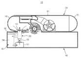
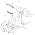
도 1은 본 발명의 일 실시예에 따른 청소시스템을 나타낸 도면이다.
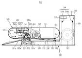
도 2는 일 실시예에 따른 로봇청소기의 단면을 나타낸 도면이다.
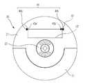
도 3은 일 실시예에 따른 로봇청소기의 저면을 나타낸 도면이다.
도 4a는 일 실시예에 따른 먼지감지유닛을 나타낸 평면도이다.
도 4b는 다른 실시예에 따른 먼지감지유닛을 나타낸 평면도이다.
도 4c는 또 다른 실시예에 따른 먼지감지유닛을 나타낸 평면도이다.
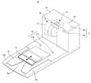
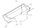
도 5a는 일 실시예에 따른 메인터넌스 스테이션의 상부 사시도이다.
도 5b는 다른 실시예에 따른 메인터넌스 스테이션의 상부 사시도이다.
도 5c는 또 다른 실시예에 따른 메인터넌스 스테이션의 상부 사시도이다.
도 5d는 또 다른 실시예에 따른 메인터넌스 스테이션의 상부 사시도이다.
도 5e는 또 다른 실시예에 따른 메인터넌스 스테이션의 측 단면도이다.
도 6은 도 4a의 실시예에 따른 메인터넌스 스테이션의 덕트를 나타낸 평면도이다.
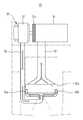
도 7은 도 4a의 실시예에 따른 메인터넌스 스테이션의 측 단면도이다.
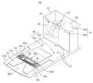
도 8은 일 실시예에 따른 로봇청소기와 메인터넌스 스테이션의 도킹 모습을 나타낸 단면도이다.
도 9a는 일 실시예에 따른 브러시 청소부재를 나타낸 사시도이다.
도 9b는 다른 실시예에 따른 브러시 청소부재를 나타낸 사시도이다.
도 9c는 또 다른 실시예에 따른 브러시 청소부재는 나타낸 사시도이다.
도 10은 다른 실시예에 따른 청소시스템을 개략적으로 나타낸 도면이다.
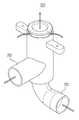
도 11은 다른 실시예에 따른 흡/배기이중관을 나타낸 사시도이다.
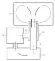
도 12는 다른 실시예를 나타낸 청소시스템의 공기 유동을 나타낸 도면이다.
도 13은 또 다른 실시예에 따른 청소시스템을 개략적으로 나타낸 도면이다.
도 14는 또 다른 실시예에 따른 청소시스템을 개략적으로 나타낸 도면이다.
도 15는 또 다른 실시예에 따른 메인터넌스 스테이션의 상부 사시도이다.
도 16은 또 다른 실시예에 따른 메인터넌스 스테이션의 일부 분해 사시도이다.
도 17은 또 다른 실시예에 따른 메인터넌스 스테이션의 덕트를 나타낸 평면도이다.
도 18은 도킹 시 제2개구부에서의 배기유동을 나타낸 측 단면도이다.
도 19는 도킹 시 제2개구부에서의 흡입유동을 나타낸 측 단면도이다.
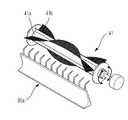
도 20은 또 다른 실시예에 따른 포트어셈블리를 나타낸 상부 사시도이다.
도 21은 또 다른 실시예에 따른 포트어셈블리를 나타낸 저면 사시도이다.1 is a view showing a cleaning system according to an embodiment of the present invention.
2 is a cross-sectional view of a robot cleaner according to an embodiment.
3 is a view showing the bottom of the robot cleaner according to an embodiment.
Figure 4a is a plan view showing a dust detection unit according to an embodiment.
Figure 4b is a plan view showing a dust detection unit according to another embodiment.
Figure 4c is a plan view showing a dust detection unit according to another embodiment.
5A is a top perspective view of a maintenance station according to one embodiment.
5B is a top perspective view of a maintenance station according to another embodiment.
5C is a top perspective view of a maintenance station according to another embodiment.
5D is a top perspective view of a maintenance station according to another embodiment.
5E is a side cross-sectional view of a maintenance station according to another embodiment.
FIG. 6 is a plan view illustrating a duct of a maintenance station according to the embodiment of FIG. 4A.
7 is a side cross-sectional view of the maintenance station according to the embodiment of FIG. 4A.
8 is a cross-sectional view illustrating a docking state of the robot cleaner and the maintenance station, according to an exemplary embodiment.
9A is a perspective view illustrating a brush cleaning member according to an embodiment.
9B is a perspective view illustrating a brush cleaning member according to another embodiment.
Figure 9c is a perspective view of a brush cleaning member according to another embodiment.
10 is a view schematically showing a cleaning system according to another embodiment.
11 is a perspective view showing an intake / exhaust double pipe according to another embodiment.
12 is a view showing the air flow of the cleaning system according to another embodiment.
13 is a schematic view of a cleaning system according to another embodiment.
14 is a schematic view of a cleaning system according to another embodiment.
15 is a top perspective view of a maintenance station according to another embodiment.
16 is a partially exploded perspective view of a maintenance station according to another embodiment.
17 is a plan view illustrating a duct of a maintenance station according to still another embodiment.
18 is a side cross-sectional view showing the exhaust flow at the second opening when docking.
19 is a side sectional view showing suction flow in a second opening when docking.
20 is a top perspective view illustrating a port assembly according to another embodiment.
21 is a bottom perspective view illustrating a port assembly according to another embodiment.
이하, 각 실시예에 따른 로봇청소기, 메인터넌스 스테이션 그리고 청소시스템에 대하여 첨부도면을 참조하여 상세히 설명한다.Hereinafter, the robot cleaner, the maintenance station, and the cleaning system according to each embodiment will be described in detail with reference to the accompanying drawings.
도 1은 본 발명의 일 실시예에 따른 청소시스템을 나타낸 도면이다.1 is a view showing a cleaning system according to an embodiment of the present invention.
도 1에 도시된 바와 같이, 청소시스템(10)은 로봇청소기(20)와 메인터넌스 스테이션(60)을 포함하여 구성될 수 있다. 로봇청소기(20)는 자율적으로 주행하면서 여러 가지 청소 임무를 수행하는 장치이고, 메인터넌스 스테이션(60)은 일종의 유지보수 장치로써, 로봇청소기(20)의 배터리를 충전하거나 로봇청소기(20)의 먼지통을 비워 주는 장치이다.As shown in FIG. 1, the
도 2는 일 실시예에 따른 로봇청소기의 단면을 나타낸 도면이고, 도 3은 일 실시예에 따른 로봇청소기의 저면을 나타낸 도면이다.2 is a view showing a cross-section of the robot cleaner according to an embodiment, Figure 3 is a view showing the bottom of the robot cleaner according to an embodiment.
도 1 내지 도 3에 도시된 바와 같이, 로봇청소기(20)는 본체(21)와 구동장치(30), 클리닝장치(40), 각종 센서(50), 제어부(미도시)를 포함하여 구성될 수 있다.As shown in FIGS. 1 to 3, the
본체(21)는 다양한 형상을 가질 수 있다. 일 예로 본체(21)는 원형으로 형성될 수 있다. 이러한 본체(21)는 회전하는 경우에도 회전 반경이 일정하여 주변 장애물과의 접촉을 피할 수 있고 방향 전환을 매우 쉽게 할 수 있다. 그리고 주행 중 주변 장애물에 걸려서 본체(21)가 움직이지 못하게 되는 것을 방지할 수 있다.The
본체(21)에는 청소 임무를 수행하기 위한 다양한 구성요소 즉, 구동장치(30)와 클리닝장치(40), 각종 센서(50), 디스플레이(23), 제어부(미도시)가 설치될 수 있다.The
구동장치(30)는 본체(21)가 청소 영역을 주행하도록 할 수 있다. 구동장치(30)는 좌우 구동바퀴(31a, 31b)와 캐스터(32)를 포함하여 구성될 수 있다. 좌우 구동바퀴(31a, 31b)는 본체(21) 하부의 중앙 영역에 장착되고 캐스터(32)는 본체(21) 하부의 전방 영역에 장착되어 로봇청소기(20)가 안정된 자세를 유지하도록 할 수 있다.The driving
좌우 구동바퀴(31a, 31b)는 로봇청소기(20)를 전진 또는 후진시키거나 방향 전환하도록 제어될 수 있다. 예를 들면 좌우 구동바퀴(31a, 31b)를 동일하게 제어하여 로봇청소기(20)가 전방 또는 후방으로 주행하도록 할 수 있고, 좌우 구동바퀴(31a, 31b)를 따로따로 제어하여 로봇청소기(20)가 방향을 전환하도록 할 수 있다.The left and
한편, 좌우 구동바퀴(31a, 31b)와 캐스터(32) 각각은 하나의 어셈블리로 구성되어 본체(21)에 착탈 가능하게 장착될 수 있다.On the other hand, the left and right driving wheels (31a, 31b) and each
클리닝장치(40)는 본체(21)의 바닥 및 그 주변을 청소하도록 할 수 있다. 브러시유닛(41)과 사이드브러시(42), 제1먼지통(43)을 포함하여 구성될 수 있다.The
브러시유닛(41)은 본체(21)의 저면에 형성된 제1개구부(21a)에 장착될 수 있다. 브러시유닛(41)은 본체(21)의 중앙 영역을 벗어난 위치에 마련될 수 있다. 즉 브러시유닛(41)은 구동바퀴(31a, 31b)에 인접한 위치에 마련되되, 구동바퀴(31a, 31b)보다 본체(21)의 후방(R)으로 치우쳐서 장착될 수 있다.The
브러시유닛(41)은 본체(21)의 바닥에 쌓인 먼지를 제1먼지통(43)에 쓸어 담을 수 있다. 브러시유닛(41)은 본체(21)의 제1개구부(21a)에 회전 가능하게 마련되는 롤러(41a)와, 이 롤러(41a)의 외주면에 박혀 있는 브러시(41b)를 포함하여 구성될 수 있다. 롤러(41a)가 회전하면, 탄성 재질로 형성되는 브러시(41b)는 바닥에 쌓인 먼지를 휘저을 수 있다. 이러한 동작에 의해서 바닥에 쌓인 먼지는 제1개구부(21a)를 통과하여 제1먼지통(43)에 저장될 수 있다.The
브러시유닛(41)은 청소 성능을 일정하게 유지하기 위해 등속 제어될 수 있다. 브러시유닛(41)은 카펫과 같이 매끄럽지 않은 바닥 면을 청소하는 경우 매끄러운 바닥 면을 청소하는 경우에 비해서 회전 속도가 떨어질 수 있는데, 이때 전류 등을 더 공급하여 브러시유닛(41)의 회전 속도를 일정하게 유지할 수 있다.The
사이드브러시(42)는 본체(21)의 저면의 테두리 일측에 회전 가능하게 장착될 수 있다. 사이드브러시(42)는 본체(21)의 중앙 영역을 벗어나서 본체(21)의 전방(F) 사선 방향으로 치우쳐서 장착될 수 있다.The
사이드브러시(42)는 본체(21)의 주변에 쌓인 먼지를 브러시유닛(41)으로 이동시킬 수 있다. 사이드브러시(42)는 로봇청소기(20)의 청소 범위를 본체(21)의 바닥 및 그 주변으로 확장시킬 수 있다. 브러시유닛(41)으로 이동된 먼지는 앞서 설명한 바와 같이 제1개구부(21a)를 통하여 제1먼지통(43)에 저장될 수 있다.The
제1먼지통(43)은 본체(21)의 후방에 장착될 수 있다. 제1먼지통(43)의 유입구(43')는 본체(21)의 제1개구부(21a)와 연통됨으로써 먼지가 제1먼지통(43)으로 유입되도록 할 수 있다.The
제1먼지통(43)은 분리벽(43c)에 의해서 큰 먼지통(43a)과 작은 먼지통(43b)으로 분리될 수 있다. 브러시유닛(41)은 제1유입구(43a')를 통하여 큰 먼지통(43a)에 비교적 큰 먼지를 쓸어 담을 수 있고, 송풍유닛(22)는 제2유입구(43b')를 통하여 작은 먼지통(43b)에 머리카락 등 부유하는 작은 먼지를 흡입하여 저장할 수 있다. 특히 제2유입구(43b')의 인접한 곳에는 브러시청소부재(41c)가 마련되는데, 브러시 청소부재(41c)는 브러시유닛(41)에 감긴 머리카락을 걸러 낸 후 송풍유닛(22)의 흡입력에 의해서 제2유입구(43b')를 통하여 작은 먼지통(43b)에 저장되도록 할 수 있다.The
한편, 브러시유닛(41)과 사이드브러시(42), 제1먼지통(43) 각각은 하나의 어셈블리로 구성되어 본체(21)에 착탈 가능하게 장착될 수 있다.On the other hand, each of the
도 4a는 일 실시예에 따른 먼지감지유닛을 나타낸 평면도이고, 도 4b는 다른 실시예에 따른 먼지감지유닛을 나타낸 평면도이다. 도 4c는 또 다른 실시예에 따른 먼지감지유닛을 나타낸 평면도이다.Figure 4a is a plan view showing a dust detection unit according to an embodiment, Figure 4b is a plan view showing a dust detection unit according to another embodiment. Figure 4c is a plan view showing a dust detection unit according to another embodiment.
도 4a에 도시된 바와 같이, 먼지감지유닛(44)은 제1먼지통(43)의 먼지량을 감지할 수 있도록 제1먼지통(43) 내부에 설치될 수 있다.As shown in FIG. 4A, the
먼지감지유닛(44)은 발광센서(44a)와 수광센서(44b)를 포함하여 구성될 수 있다. 제1먼지통(43) 내부에서 발광센서(44a)에서 송출되는 신호는 수광센서(44b)에 직접적으로 수신될 수 있다.The
발광센서(44a)와 수신센서(44b)는 포토 다이오드(Photo Diode) 또는 포토 트랜지스터(Photo Transistor)를 포함하여 구성될 수 있다. 이 경우 포토 다이오드(Photo Diode) 또는 포토 트랜지스터(Photo Transistor)에 감지되는 에너지량을 기준으로 제1먼지통(43)에 먼지가 가득 찼는지 여부를 판단할 수 있다. 즉 먼지가 쌓이게 되면 포토 다이오드(Photo Diode) 또는 포토 트랜지스터(Photo Transistor)에 감지되는 에너지량이 현격히 감소될 수 있고, 이 에너지량을 미리 설정된 기준 값과 비교한 후 에너지량이 기준 값보다 작은 경우 제어부는 제1먼지통(43)에 먼지가 가득 찬 것으로 판단할 수 있다. 이처럼 포토 다이오드(Photo Diode) 또는 포토 트랜지스터(Photo Transistor)로 구성되는 발광센서(44a)와 수신센서(44b)는 외란 영향을 많이 받기 때문에 발광센서(44a)와 수신센서(44b)의 신호를 가이드하는 슬릿이나 광 가이드와 같은 구조물이 설치하는 경우 보다 정확하게 먼지 유무를 감지할 수 있다.The
또한, 발광센서(44a)와 수신센서(44b)는 리모컨 수신모듈로 구성될 수 있다. 이 경우 수신센서(44b)에 신호가 전달되었는지 여부를 기준으로 제1먼지통(43)에 먼지가 가득 찼는지 판단할 수 있다. 즉 먼지가 쌓이게 되면 발광센서(44a)에서 송출하는 신호를 수광센서(44b)가 수신하지 못하게 되고, 제어부는 제1먼지통(43)에 먼지량이 일정량 이상 채워져 있는 것으로 판단할 수 있다. 이처럼 리모컨 수신모듈로 구성되는 발광센서(44a)와 수신센서(44b)는 저주파를 필터링하고, 강도 및 수신감도가 높아서 슬릿이나 광 가이드 구조물이 필요하지 않을 수 있다.In addition, the
여기서 발광센서(44a)와 수광센서(44b)가 송수신하는 신호에는 가시광선, 적외선, 음파, 초음파 등이 사용될 수 있다.Here, visible light, infrared rays, sound waves, ultrasonic waves, and the like may be used as signals transmitted and received by the
또한 도 4B에 도시된 바와 같이, 먼지감지유닛(44)은 발광센서(44a), 수광센서(44b) 그리고 반사부재(44c)를 포함하여 구성될 수 있다.In addition, as shown in FIG. 4B, the
발광센서(44a)와 수광센서(44b)는 제1먼지통(43) 내부에 설치되지 않고 제1먼지통(43) 이외의 부분에 설치될 수 있다. 즉, 발광센서(44a)와 수광센서(44b)는 제1먼지통(43)과 마주보는 본체(21)의 일 부분에 설치될 수 있다. 구체적으로, 발광센서(44a)와 수광센서(44b)는 제1먼지통(43)의 유입구(43')와 인접한 위치에 설치될 수 있다. 따라서 발광센서(44a)는 제1먼지통(43)의 유입구(43')를 통하여 제1먼지통(43) 내부로 신호를 송출할 수 있고, 수광센서(44b)는 제1먼지통(43)의 유입구(43')를 통하여 제1먼지통(43) 바깥으로 빠져 나오는 신호를 수신할 수 있다.The
반사부재(44c)는 제1먼지통(43) 내부에 설치될 수 있다. 반사부재(44c)는 발광센서(44a)에서 송출하는 신호를 수광센서(44b)가 있는 방향으로 반사할 수 있다.The
제1먼지통(43)에 먼지가 가득 찬 경우 반사부재(44c)는 먼지에 의해서 가려지기 때문에 발광센서(44a)에서 발신하는 신호는 수광센서(44b)에 수신되지 않거나, 수광센서(44b)에 수신되는 에너지량이 현격히 감소될 수 있다. 이때 제어부는 제1먼지통(43)에 먼지가 일정량 이상이 채워진 것으로 판단할 수 있다.When the
한편, 앞서 언급한 바와 같이, 발광센서(44a)와 수광센서(44b)가 리모컨모듈로 구성되는 경우 저주파를 필터링하고, 강도 및 수신감도가 높아서 슬릿이나 광가이드 구조물이 필요하지 않을 수 있다. 즉 제1먼지통(43) 내부에 반사부재(44c)와 같은 구조물이 없더라도 리모콘 모듈로 구성되는 발광센서(44a)와 수광센서(44b)는 먼지가 가득 찼는지를 판단할 수 있다.On the other hand, as mentioned above, when the
이처럼 발광센서(44a)와 수광센서(44b)를 제1먼지통(43)의 내부에 설치하지 않아도 되기 때문에 제1먼지통(43) 내부에 전기적 연결단자를 설치할 필요가 없다. 이에 사용자는 제1먼지통(43)을 물로 세척할 수 있다.As such, since the
또한 도 4C에 도시한 바와 같이, 먼지감지유닛(44)는 발광센서(44a)와 수광센서(44b)를 포함하여 구성될 수 있다.In addition, as shown in FIG. 4C, the
발광센서(44a)와 수광센서(44b)는 제1먼지통(43) 내부에 설치되지 않고 제1먼지통(43) 이외의 부분에 설치될 수 있다. 즉, 발광센서(44a)와 수광센서(44b)는 본체(21)에 서로 대향되게 설치될 수 있다. 구체적으로, 발광센서(44a)는 제1먼지통(43)의 일측과 마주보는 본체(21)의 일 부분에 설치되고, 수광센서(44b)는 제1먼지통(43)의 타측과 마주보는 본체(21)의 타부분에 설치될 수 있다. 이때 제1먼지통(43)은 발광센서(44a)와 수광센서(44b) 사이에 위치되기 때문에 발광센서(44a)에서 송출하는 신호는 제1먼지통(43)을 관통하여 수광센서(44b)에 수신될 수 있다. 여기서 제1먼지통(43)은 전체가 투명하게 형성되어 신호가 관통되도록 구성될 수 있고, 제1먼지통(43)에는 발광센서(44a)와 대응하는 위치에 신호가 통과하도록 투명하게 형성되는 송출신호 통과부(43a")와 수광센서(44b)와 대응하는 위치에 신호가 통과하도록 투명하게 형성되는 도달신호 통과부(43b")가 부분적으로 형성될 수 있다.The
발광센서(44a)에서 송출되는 신호는 수신센서(44b)에 직접적으로 수신될 수 있다. 제1먼지통(43)에 먼지가 가득 찬 경우 수신센서(44b)에 신호가 감지되지 않거나, 감지되는 에너지량이 현격히 감소될 수 있다. 이 경우 제어부는 제1먼지통(43)에 먼지가 가득 찬 것으로 판단할 수 있다.The signal transmitted from the
또한, 제1먼지통(43)에는 전기적 연결구조가 설치되지 않기 때문에 사용자는 제1먼지통(43)을 물로 세척하는 것도 가능할 수 있다.In addition, since the electrical connection structure is not installed in the
먼지감지유닛(44)이 일정량 이상의 먼지를 감지하는 경우 로봇청소기(20)는 디스플레이(23)에 이에 대한 정보를 표시할 수 있다. 사용자는 직접 제1먼지통(43)을 청소하는 것이 가능하다. 한편 로봇청소기(20)는 자동으로 메인터넌스 스테이션(60)에 도킹하여 제1먼지통(43)에 저장된 먼지를 자동으로 배출하는 것도 가능하다.When the
각종 센서(50)는 본체(21)에 장착되어 장애물을 감지하는데 사용될 수 있다. 이러한 센서에는 접촉센서 또는 근접센서 등이 사용될 수 있다. 예를 들면 본체(21)의 전방(F)에 설치되는 범퍼(51)는 벽 등의 전방 장애물을 감지하는데 사용될 수 있다. 또한, 적외선 센서(또는 초음파 센서)를 이용하여 전방 장애물을 감지하는 것도 가능할 수 있다.
또한, 본체(21)의 저면에 설치되는 적외선 센서(52)(또는 초음파 센서)는 계단 등의 바닥 상태를 감지하는데 사용될 수 있다. 복수 개의 적외선 센서(52)가 본체(21)의 저면에 반원호형 둘레를 따라서 설치된다.In addition, the infrared sensor 52 (or the ultrasonic sensor) installed on the bottom of the
이 밖에도 다양한 센서들이 본체(21)에 설치되어 로봇청소기(20)의 상태를 제어부에 전달할 수 있다.In addition, various sensors may be installed in the
제어부는 각종 센서(50)로부터 신호를 입력받아 구동장치(30)와 클리닝장치(40)를 제어함으로서 로봇청소기(20)를 보다 효율적으로 제어할 수 있다.The control unit may control the
도 5a는 일 실시예에 따른 메인터넌스 스테이션의 상부 사시도이고, 도 5b는 다른 실시예에 따른 메인터넌스 스테이션의 상부 사시도이고, 도 5c는 또 다른 실시예에 따른 메인터넌스 스테이션의 상부 사시도이고, 도 5d는 또 다른 실시예에 따른 메인터넌스 스테이션의 상부 사시도이고, 도 5e는 또 다른 실시예에 따른 메인터넌스 스테이션의 측 단면도이고, 도 6는 도 5a의 실시예에 따른 메인터넌스 스테이션의 덕트를 나타낸 평면도이고, 도 7은 도 5a의 실시예에 따른 메인터넌스 스테이션의 측 단면도이다.5A is a top perspective view of a maintenance station according to one embodiment, FIG. 5B is a top perspective view of a maintenance station according to another embodiment, FIG. 5C is a top perspective view of a maintenance station according to another embodiment, and FIG. 5D is another 5 is a side cross-sectional view of a maintenance station according to another embodiment, FIG. 6 is a plan view illustrating a duct of the maintenance station according to the embodiment of FIG. 5A, and FIG. Side sectional view of a maintenance station according to the embodiment of FIG. 5A.
도 1 내지 도 7에 도시된 바와 같이, 로봇청소기(20)는 여러 가지 상황에서 메인터넌스 스테이션(60)에 도킹할 수 있다. 예를 들면 로봇청소기(20)의 배터리(미도시)를 충전하는 경우 또는 로봇청소기(20)가 소정 시간 동안 청소 임무를 수행한 경우, 로봇청소기(20)가 청소를 끝낸 경우, 로봇청소기(20)의 제1먼지통(43)에 먼지가 가득 찬 경우 등이 있을 수 있다.As shown in FIGS. 1 to 7, the
메인터넌스 스테이션(60)은 하우징(61)과 도킹유도장치(70), 충전장치(80), 먼지제거장치(90), 제어부(미도시)를 포함하여 구성될 수 있다.The
하우징(61)에는 플랫폼(62)이 마련될 수 있다. 로봇청소기(20)가 메인터넌스 스테이션(60)에 도킹될 때 플랫폼(62)은 로봇청소기(20)를 지지할 수 있다.The
플랫폼(62)은 비스듬히 마련되어 로봇청소기(20)가 플랫폼(62)에 쉽게 오르거나 내리도록 할 수 있다. 플랫폼(62)에는 로봇청소기(20)의 캐스터(32)를 가이드하는 캐스터 가이드부(63a)가 형성되고, 로봇청소기(20)의 좌우 구동바퀴(31a, 31b)를 가이드하는 구동바퀴 가이드부(63b, 63c)가 형성될 수 있다. 캐스터 가이드부(63a)와 구동바퀴 가이드부(63b, 63c) 각각은 주변보다 함몰되어 형성될 수 있다.The
플랫폼(62)에는 제2개구부(62a)가 형성될 수 있다. 플랫폼(62)의 제2개구부(62a)는 로봇청소기(20)의 제1개구부(21a)와 연통될 수 있는 위치에 마련될 수 있다. 이에 로봇청소기(20)의 제1개구부(21a)로 배출되는 먼지는 플랫폼(62)의 제2개구부(62a)로 유입될 수 있다. 플랫폼(62)의 제2개구부(62a)로 유입되는 먼지는 메인터넌스 스테이션(60)의 제2먼지통(94)에 저장될 수 있다.A
메인터넌스 스테이션(60)의 제2먼지통(94)은 로봇청소기(20)의 제1먼지통(43)과는 다른 것이다. 로봇청소기(20)의 제1먼지통(43)은 로봇청소기(20)가 이동하면서 바닥에서 모은 먼지를 저장하는 것이고, 메인터넌스 스테이션(60)의 제2먼지통(94)은 로봇청소기(20)의 제1먼지통(43)에서 배출되는 먼지를 모아서 저장하는 것이다. 이에 메인터넌스 스테이션(60)의 제2먼지통(94)의 용량은 로봇청소기(20)의 제1먼지통(43)의 용량보다 크게 형성될 수 있다.The
먼지감지유닛(44)은 제2먼지통(94)의 먼지량을 감지할 수 있도록 제2먼지통(94) 내부에도 설치될 수 있다.The
먼지감지유닛(44)은 발광센서(44a)와 수광센서(44b)를 포함하여 구성될 수 있다. 발광센서(44a)에서 발신하는 신호를 수광센서(44b)가 수신하지 못하는 경우 제어부는 제2먼지통(94)에 먼지량이 일정량 이상 채워져 있는 것으로 판단할 수 있다.The
플랫폼(62)의 제2개구부(62a)는 도 5a에 나타낸 것처럼 개방된 상태로 마련될 수 있다. 즉, 플랫폼(62)의 제2개구부(62a)에는 별도의 커버가 설치되지 않고 항상 개방된 상태로 마련될 수 있다.The
플랫폼(62)은 소정 각도(θ) 이상으로 기울어져 형성될 수 있다.(도 7참조) 로봇청소기(20)가 소정 각도(θ) 이상으로 기울어진 플랫폼(62)을 지나가는 경우 로봇청소기(20)의 무게가 후방으로 치우쳐지기 때문에 로봇청소기(20)의 전방은 약간 들려진 상태가 될 수 있다. 따라서 로봇청소기(20)의 캐스터(32)는 플랫폼(62)의 제2개구부(62a)에 빠지지 않고 건너갈 수 있다.The
한편, 플랫폼(62)의 제2개구부(62a)에는 도 5b에 나타낸 것처럼 커버(64)가 슬라이딩 왕복 가능하게 설치될 수 있다. 로봇청소기(20)의 도킹 완료 시 커버(64)는 열린 상태로 되어 로봇청소기(20)의 먼지가 플랫폼(62)의 제2개구부(62a)로 배출될 수 있도록 할 수 있다. 반대로 로봇청소기(20)의 도킹 해제 시 커버(64)는 닫힌 상태로 되어 플랫폼(62)의 제2개구부(62a)를 폐쇄할 수 있다.Meanwhile, as shown in FIG. 5B, the
또한 커버(64)는 로봇청소기(20)의 캐스터(32)가 지나가는 다리 역할을 할 수 있다. 커버(64)는 로봇청소기(20)의 도킹과 연동되어 개폐될 수 있다. 즉, 로봇청소기(20)의 도킹 시 캐스터(32)가 커버(64)를 지나가는 도중 또는 지나간 후에 커버(64)는 열릴 수 있고, 도킹 해제 시 캐스터(32)가 커버(64)를 지나가거나 지나간 후에 커버(64)는 닫힐 수 있다. 또한 별도의 장치를 사용하여 커버(64)를 개폐시킬 수도 있다.In addition, the
한편, 플랫폼(62)의 제2개구부(62a)에는 도 5c에 나타낸 것처럼 커버(65)가 슬라이딩 왕복 가능하게 설치될 수 있다. 다만 도 5c는 도 5b와 다르게 커버(65)가 플랫폼(62)의 제2개구부(62a)의 중앙 영역만에 설치될 수 있다. 로봇청소기(20)의 캐스터(32)가 플랫폼(62)의 제2개구부(62a)를 지나가도록 하기 위함이다. 커버(65)의 개폐동작은 앞서 설명한 바와 동일할 수 있다.Meanwhile, as shown in FIG. 5C, the
한편, 플랫폼(62)의 제2개구부(62a)에는 도 5d에 나타낸 것처럼 브릿지(66)가 설치될 수 있다. 브릿지(66)는 플랫폼(62)의 제2개구부(62a)의 중앙 영역에만 설치되어 로봇청소기(20)의 캐스터(32)가 지나가는 다리 역할을 할 수 있다.On the other hand, the
또한 플랫폼(62)의 제2개구부(62a)에는 도 5e에 나타낸 것처럼 브릿지(66)가 상하 방향으로 왕복 가능하게 설치될 수 있다. 로봇청소기(20)가 플랫폼(62)에 진입하는 경우 브릿지(67a)는 상승하여 로봇청소기(20)의 캐스터(32)가 건너가도록 하고, 도킹 완료된 경우 브릿짓(67b)는 하강하여 플랫폼(62)의 제2개구부(62a)의 개구 면적을 크게 확보할 수 있다.In addition, as shown in FIG. 5E, the
도킹유도장치(70)는 하우징(61)의 상부에 설치될 수 있다. 도킹유도장치(70)는 복수 개의 센서(71)를 포함하여 구성되고, 이들 복수 개의 센서(71)는 도킹 유도 영역과 도킹 영역을 형성함으로써 로봇청소기(20)가 메인터넌스 스테이션(60)에 정확하게 도킹되도록 가이드할 수 있다.The
충전장치(80)는 플랫폼(62)에 설치될 수 있다. 충전장치(80)는 복수 개의 접속단자(81a, 81b)를 포함하여 구성될 수 있고, 이들 접속단자(81a, 81b)는 로봇청소기(20)의 복수 개의 접속단자(23a, 23b)와 대응하는 위치에 형성될 수 있다. 로봇청소기(20)의 도킹이 완료되면 메인터넌스 스테이션(60)의 복수 개의 접속단자(81a, 81b)를 통하여 로봇청소기(20)의 복수 개의 접속단자(23a, 23b)에 전류를 공급할 수 있다.The charging
충전장치(80)는 로봇청소기(20)의 복수 개의 접속단자(23a, 23b)의 접속 여부를 판단한 후 전류를 공급할 수 있다. 로봇청소기(20)의 복수 개의 접속단자(23a, 23b) 이외에 다른 무언가가 접속되는 경우에는 전류 공급을 차단함으로써 불의의 사고를 방지할 수 있다.The charging
하우징(61)에는 먼지제거장치(90)가 설치될 수 있다. 먼지제거장치(90)는 로봇청소기(20)의 제1먼지통(43)에 저장된 먼지를 메인터넌스 스테이션(60)의 제2먼지통(94)으로 비워 줌으로써 로봇청소기(20)의 청소 성능을 일정하게 유지시킬 수 있다.The
먼지제거장치(90)는 펌프유닛(91)과 흡입덕트(92), 배기덕트(93), 제2먼지통(94)을 포함하여 구성될 수 있다. 먼지제거장치(90)는 배기덕트(93)에서 배기되는 유동이 다시 흡입덕트(92)로 흡입되도록 하고, 이와 같은 환류를 이용하여 로봇청소기(20)의 제1먼지통(43)에 저장된 먼지를 제거하는 장치이다.The
펌프유닛(91)은 공기를 흡입/배출하는 장치이다. 펌프유닛(91)은 팬과 모터 등을 포함하여 구성될 수 있다.The
펌프유닛(91)의 공기 흡입 방향에는 흡입덕트(92)가 설치될 수 있다. 흡입덕트(92)의 흡입포트(92a)는 제2개구부(62a)의 일부를 형성할 수 있다. 또는 제2개구부(62a)와는 별도로 제2개구부(62a)에 인접한 위치에 마련될 수 있다.The
흡입포트(92a)는 제2개구부(62a)의 길이 방향을 따라 형성되어, 제2개구부(62a)에서 배기포트(93a, 93b)가 점유하는 면적을 제외한 나머지 부분을 점유할 수 있다.The
펌프유닛(91)의 공기 배출 방향에는 배기덕트(93)가 설치될 수 있다. 배기덕트(93)는 분기되어 2개의 배기포트(93a, 93b)를 형성하고, 이들 배기포트(93a, 93b)는 제2개구부(62a)의 일부를 형성할 수 있다. 또는 제2개구부(62a)와는 별도로 제2개구부(62a)에 인접한 위치에 마련될 수 있다.An
배기포트(93a, 93b)는 제2개구부(62a)의 길이 방향 단부 측 즉, 양 사이드 영역에 형성될 수 있다.The
흡입덕트(92)의 흡입포트(92a)의 단면적은 배기덕트(93)의 배기포트(93a, 93b)의 단면적보다 크게 형성될 수 있다. 바람직하게는 흡입포트(92a)의 단면적과 배기포트(93a, 93b)의 단면적의 비율은 7.5 : 1 로 형성될 수 있다. 이와 더불어 배기포트(93a, 93b)에 대한 흡입포트(92a)의 단면적 비율을 조금 작게 설정할 수 있다. 즉, 7 : 1 또는 6.5 : 1 또는 6 : 1 처럼 각 포트의 단면적 비율을 조금 작게 설정하더라도 본 발명의 기술적 범위를 벗어나는 것은 아니다.The cross-sectional area of the
결국 펌프유닛(91)의 흡입 유량과 배출 유량이 실질적으로 동일하기 때문에 각 포트의 단면적 차이에 의하여 배기덕트(93)의 배기포트(93a, 93b)에서의 공기 유속이 흡입덕트(92)의 흡입포트(92a)에서의 공기 유속보다 빠르게 형성될 수 있다. 이러한 유속 차이에 의해서 배기포트(93a, 93b)를 빠져 나온 공기가 바로 흡입포트(92a)로 빨려 들어가는 것을 방지할 수 있다. 배기포트(93a, 93b)를 빠져 나온 공기는 유속이 매우 빠르기 때문에 흡입포트(93a, 93b)에서의 흡입력에 의해서 흡입포트(93a, 93b)측으로 바로 빨려 들어가지 않고 제1먼지통(43) 내부로 분사될 수 있다. 제1먼지통(43) 내부로 분사되는 공기는 제1먼지통(43)를 순환한 후 제1먼지통(43) 밖으로 빠져 나올 수 있고, 이후 흡입포트(92a)로 유입될 수 있다.As a result, since the suction flow rate and the discharge flow rate of the
도 8은 일 실시예에 따른 로봇청소기와 메인터넌스 스테이션의 도킹 모습을 나타낸 단면도이다.8 is a cross-sectional view illustrating a docking state of the robot cleaner and the maintenance station, according to an exemplary embodiment.
도 1 내지 도 8에 도시된 바와 같이, 로봇청소기(20)가 메인터넌스 스테이션(60)에 도킹될 때 로봇청소기(20)의 제1개구부(21a)와 메인터넌스 스테이션(60)의 제2개구부(62a)는 연통될 수 있다.1 to 8, when the
도킹 시 흡입덕트(92)의 흡입포트(92a)는 로봇청소기(20)의 제1개구부(21a)에 인접한 위치에 마련될 수 있고, 로봇청소기(20)의 제1개구부(21a)의 길이 방향을 따라서 배치될 수 있다. 또한, 배기덕트(93)의 배기포트(93a, 93b)도 로봇청소기(20)의 제1개구부(21a)에 인접한 위치에 마련될 수 있고, 로봇청소기(20)의 제1개구부(21a)의 길이 방향 단부 측 즉, 사이드 영역에 배치될 수 있다.When docking, the
이러한 구조에 의해서 도킹 시 먼지제거장치(90)에 의해서 순환(또는 환류)하는 공기는 하나의 폐회로(closed loop)를 형성할 수 있다. 펌프유닛(91)에서 배출되는 공기는 배기덕트(93)의 배기포트(93a, 93b)를 빠른 유속으로 빠져나가 로봇청소기(20)의 제1개구부(21a)의 사이드 영역을 통과하여 로봇청소기(20)의 제1먼지통(43)으로 유입될 수 있다. 로봇청소기(20)의 제1먼지통(43)에 유입되는 공기는 로봇청소기(20)의 제1개구부(21a)의 중앙 영역로 배출된 후 흡입덕트(92)의 흡입포트(92a)를 통해서 메인터넌스 스테이션(60)의 제2먼지통(94)으로 유입된 후 다시 펌프유닛(91)으로 흡입될 수 있다.With this structure, air circulating (or refluxed) by the
도 9a는 일 실시예에 따른 브러시 청소부재를 나타낸 도면이고, 도 9b는 다른 실시예에 따른 브러시 청소부재를 나타낸 도면이고, 도 9c는 또 다른 실시예에 다른 브러시 청소부재를 나타낸 도면이다.9A is a view showing a brush cleaning member according to an embodiment, FIG. 9B is a view showing a brush cleaning member according to another embodiment, and FIG. 9C is a view showing another brush cleaning member according to another embodiment.
도 9a에 도시된 바와 같이, 메인터넌스 스테이션(60)은 로봇청소기(20)의 브러시유닛(41)을 청소할 수 있는 브러시청소부재(95a)를 포함하여 구성될 수 있다. 메인터넌스 스테이션(60)의 브러시청소부재(95a)는 로봇청소기(20)의 브러시청소부재(41c)와 다른 것이다.As shown in FIG. 9A, the
메인터넌스 스테이션(60)의 브러시청소부재(95a)는 제2개구부(62a)에 인접한 위치에 마련될 수 있다. 메인터넌스 스테이션(60)의 브러시청소부재(95a)는 하우징(61)의 바닥에서 제2개구부(62a)를 향하여 돌출 형성될 수 있고, 제2개구부(62a)의 길이 방향을 따라서 복수 개로 형성될 수 있다.The
도킹 시 메인터넌스 스테이션(60)의 브러시청소부재(95a)는 로봇청소기(20)의 브러시유닛(41)과 접촉할 수 있다. 메인터넌스 스테이션(60)의 브러시청소부재(95a)는 로봇청소기(20)의 브러시유닛(41)에 감긴 머리카락 등의 이물질을 걸러 낼 수 있다. 특히 메인터넌스 스테이션(60)의 브러시청소부재(95a)는 흡입덕트(92)에 마련될 수 있기 때문에 메인터넌스 스테이션(60)의 브러시청소부재(95a)에 의해서 걸러진 이물질은 펌프유닛(91)의 흡입력에 의해서 제2먼지통(94)으로 유입될 수 있다.When docking, the
다른 실시예로, 도 9b에 도시된 바와 같이, 메인터넌스 스테이션(60)의 브러시 청소부재(95b)는 제2개구부의 길이 방향을 따라서 슬라이딩 왕복 가능하게 설치될 수 있다. 메인터넌스 스테이션(60)의 브러시 청소부재(95b)가 슬라이딩하는 동안 로봇청소기(20)의 브러시유닛(41)에 감긴 이물질을 걸러 낼 수 있다.In another embodiment, as shown in FIG. 9B, the
또 다른 실시예로, 도 9c에 도시된 바와 같이, 메인터넌스 스테이션(60)의 브러시 청소부재(95c)는 상하 방향으로 왕복 가능하게 설치될 수 있다. 로봇청소기의 도킹이 완료된 경우 브러시 청소부재(95c)는 상승하여 로봇청소기(20)의 브러시유닛(41)과 접촉할 수 있고, 도킹이 해제된 경우 브러시 청소부재(95c)는 다시 하강할 수 있다. 한편, 브러시 청소부재(95c)의 상하방향 왕복 운동은 로봇청소기(20)의 도킹과 연동될 수 있다.In another embodiment, as shown in FIG. 9C, the
로봇청소기(20)의 브러시유닛(41)은 먼지제거장치(90)와 협조하여 먼지를 더욱 원활하게 이동시킬 수 있다. 먼지제거장치(90)가 공기를 순환시키는 경우 로봇청소기(20)의 브러시유닛(41)은 도 8에서 시계 방향으로 회전할 수 있다. 이때 로봇청소기(20)의 브러시유닛(41)은 배기덕트(93)의 배기포트(93a, 93b)에서 배기되는 공기가 로봇청소기(20)의 제1먼지통(43)으로 더욱 쉽게 유입되도록 도울 수 있고, 로봇청소기(20)의 제1먼지통(43)에서 빠져 나온 공기가 흡입덕트(92)의 흡입포트(92a)로 더욱 쉽게 유입되도록 도울 수 있다.
또한, 로봇청소기(20)의 브러시유닛(41)은 회전 속도를 다르게 하여 먼지를 더욱 원활하게 이동시킬 수 있다. 먼지제거장치(90)가 공기를 순환시키는 경우 초기에 로봇청소기(20)의 브러시유닛(41)은 상대적으로 느리게 회전하고, 그 이후에 빠르게 회전할 수 있다. 여기서 '초기'는 임의의 시간을 의미할 수 있는데, 머리카락 등 가벼운 먼지가 배출되기에 충분한 시간으로 설정될 수 있다. 이처럼 초기에 로봇청소기(20)의 브러시유닛(41)이 느리게 회전함으로써 상대적으로 가벼운 머리카락 등의 이물질이 브러시유닛(41)에 감기지 않고 먼지제거장치(90)의 흡입력에 의해서 흡입덕트(92)의 흡입포트(92a)로 쉽게 이동할 수 있고, 이후에 로봇청소기(20)의 브러시유닛(41)이 빠르게 회전함으로써 상대적으로 무거운 먼지들이 브러시유닛(41)의 회전력의 도움을 받아서 흡입덕트(92)의 흡입포트(92a)로 쉽게 이동할 수 있다.In addition, the
또한 로봇청소기(20)의 브러시유닛(41)은 적어도 한 번 회전 방향을 바꾸면서 브러시유닛(41)에 감긴 이물질을 걸러 낼 수 있다. 로봇청소기(20)의 제1먼지통(43)에 저장된 먼지는 로봇청소기(20)의 브러시유닛(41)을 거치면서 로봇청소기(20)의 제1개구부(21a)로 배출되기 때문에 로봇청소기(20)의 브러시유닛(41)에 감길 수 있다. 이때 로봇청소기(20)의 브러시유닛(41)은 회전 방향을 바꿔 줌으로써 로봇청소기(20)의 브러시유닛(41)에 감긴 이물질을 풀어 낼 수 있다. 이렇게 풀어진 이물질은 흡입덕트(92)의 흡입포트(92a)로 이동하여 메인터넌스 스테이션(60)의 제2먼지통(94)에 저장될 수 있다. 이후 로봇청소기(20)의 브러시유닛(41)은 다시 한 번 회전 방향을 바꾸어 원래 방향으로 회전할 수 있다. 또한 로봇청소기(20)의 브러시유닛(41)은 이처럼 회전방향 변경하는 것을 수 차례 반복할 수 있다.In addition, the
이하 일 실시예에 따른 청소시스템의 동작에 대해서 설명한다.Hereinafter, an operation of the cleaning system according to an embodiment will be described.
도 1 내지 도 9에 도시된 바와 같이, 로봇청소기(20)는 도킹유도장치(70)의 신호를 감지하고, 감지된 신호에 따라 메인터넌스 스테이션(60)에 정확하게 도킹될 수 있다. 도킹은 본체(21)의 전방부터 플랫폼(62)으로 진입하게 되고, 로봇청소기(20)의 제1개구부(21a)와 메인터넌스 스테이션(60)의 제2개구부(62a)가 연통될 수 있는 위치에서 완료될 수 있다.As shown in FIGS. 1 to 9, the
도킹이 완료되면 먼지제거장치(90)는 로봇청소기(20)에 저장된 먼지를 메인터넌스 스테이션(60)으로 배출시킬 수 있다. 구체적으로, 펌프유닛(91)이 배기덕트(93)의 배기포트(93a, 93b)를 통하여 공기를 빠른 유속으로 배출하고, 배기포트(93a, 93b)에서 빠져 나온 공기는 로봇청소기(20)의 제1개구부(21a)를 통과하여 제1먼지통(43)으로 유입될 수 있다. 로봇청소기(20)의 제1먼지통(43)으로 유입된 공기는 제1먼지통(43)의 사공간 없이 전체 공간을 휘저을 수 있다. 특히 배기포트(93a, 93b)는 로봇청소기(20)의 제1개구부(20a)의 길이 방향을 기준으로 그 사이드 영역에 설치되기 때문에 배기포트(93a, 93b)를 빠져 나온 공기는 제1먼지통(43)의 사이드 영역부터 전체적으로 먼지를 휘저을 수 있다. 이후 제1먼지통(43)의 저장된 먼지는 제1먼지통(43)으로 유입된 공기에 의해서 부유하면서 제1먼지통(43)으로 유입된 공기와 함께 로봇청소기(20)의 제1개구부(21a)로 빠져나갈 수 있다. 흡입덕트(92)의 흡입포트(92a)는 로봇청소기(20)의 제1개구부(21a)측에 흡입력을 발생시켜 로봇청소기(20)의 제1먼지통(43)을 빠져 나오는 먼지를 흡입할 수 있다. 이후 흡입덕트(92)의 흡입포트(92a)로 유입된 먼지는 메인터넌스 스테이션(60)의 제2먼지통(94)에 저장될 수 있고, 공기는 필터(94a)를 거쳐서 펌프유닛(91)으로 다시 흡입될 수 있다.When the docking is completed, the
이처럼 펌프유닛(91)의 배출되는 공기는 배기덕트(93), 로봇청소기(20)의 제1개구부(21a), 로봇청소기(20)의 제1먼지통(43), 로봇청소기(20)의 제1개구부(21a), 흡입덕트(92), 메인터넌스 스테이션(60)의 제2먼지통(94)을 순차적으로 통과한 후 다시 펌프유닛(91)으로 유입될 수 있다. 이처럼 공기를 순환(또는 환류)시킴에 따라 공기가 밖으로 빠져 나가는 것을 최대한 방지할 수 있기 때문에 필터(94a)의 성능을 낮출 수 있다. 또한 펌프유닛(91)을 하나만 사용하여 공기를 흡입/배출할 수 있다.As such, the air discharged from the
또한, 배기덕트(93)의 배기포트(93a, 93b)에서 배출되는 공기는 로봇청소기(20)의 제1개구부(21a) 및 메인터넌스 스테이션(60)의 제2개구부(62a)의 길이 방향에 대해 그 사이드 영역을 통하여 배출될 수 있고, 흡입덕트(92)의 흡입덕트(92)에서 흡입되는 공기는 로봇청소기(20)의 제1개구부(21a) 및 메인터넌스 스테이션(60)의 제2개구부(62a)의 길이 방향을 따라 그 대부분 영역에서 흡입될 수 있기 때문에 로봇청소기(20)의 제1먼지통(43)에 빠져 나온 먼지는 주로 로봇청소기(20)의 제1개구부(21a) 및 메인터넌스 스테이션(60)의 제2개구부(62a)의 중앙 영역을 통하여 이동할 수 있다. 이러한 흡입포트(92a)와 배기포트(93a, 93b)의 배치구조는 로봇청소기(20)의 제1먼지통(43)에 빠져 나온 먼지가 사이드 영역으로 이동하는 것을 방지하여 밖으로 빠져 나가는 것을 방지할 수 있다. 이처럼 흡입포트(92a)와 배기포트(93a, 93b)의 로봇청소기(20)의 제1개구부(21a) 및 메인터넌스 스테이션(60)의 제2개구부(62a)에 대한 위치는 로봇청소기(20)와 메인터넌스 스테이션(60) 사이에 일종의 실링 효과를 가져올 수 있다.In addition, the air discharged from the
한편, 브러시유닛(41)은 먼지제거장치(90)가 공기를 순환시키는 동안 초기에 천천히 회전하고, 이후에 빠르게 회전하도록 협조 제어될 수 있다. 구체적으로 브러시유닛(41)이 초기에 천천히 회전하는 동안 먼지제거장치(90)는 머리카락 등 가벼운 먼지를 신속하게 흡입할 수 있다. 이후에 브러시유닛(41)은 빠르게 회전하면서 먼지제거장치(90)가 대체적으로 무거운 먼지를 흡입하는 것을 도울 수 있다.On the other hand, the
또한, 브러시유닛(41)은 먼지제거장치(90)가 공기를 순환시키는 동안 적어도 한 번 회전 방향을 바꾸도록 협조 제어될 수 있다. 구체적으로 브러시유닛(41)에는 머리카락 등의 이물질이 감길 수 있는데, 그 회전 방향을 바꿈으로써 머리카락 등의 이물질이 풀리도록 할 수 있다. 이때 먼지제거장치(90)는 브러시유닛(41)의 머리카락 등의 이물질을 흡입할 수 있다.In addition, the
한편, 메인터넌스 스테이션(60)의 브러시청소부재(95)는 로봇청소기(20)의 브러시유닛(41)에 감긴 머리카락 등의 이물질을 걸러 낼 수 있다. 로봇청소기(20)의 브러시유닛(41)이 회전하는 동안 브러시유닛(41)에 감긴 이물질은 메인터넌스 스테이션(60)의 브러시청소부재(95)와 접촉함으로써 메인터넌스 스테이션(60)의 브러시청소부재(95)에 걸러질 수 있다. 이렇게 걸러진 이물질은 먼지제거장치(90)의 흡입력에 의해서 제2먼지통(94)에 저장될 수 있다.On the other hand, the
도 10은 다른 실시예에 따른 청소시스템을 개략적으로 나타낸 도면이고, 도 11은 흡/배기이중관을 나타낸 사시도이고, 도 12는 다른 실시예를 나타낸 청소시스템의 공기 유동을 나타낸 도면이다.10 is a view schematically showing a cleaning system according to another embodiment, FIG. 11 is a perspective view showing an intake / exhaust double pipe, and FIG. 12 is a view showing air flow of the cleaning system according to another embodiment.
도 10 내지 도 12에 도시된 바와 같이, 청소시스템(100)은 로봇청소기(120)의 제1먼지통(143)에 저장된 먼지를 메인터넌스 스테이션(160)의 제2먼지통(194)으로 배출할 수 있다. 이하에서는 앞의 실시예와 다른 점에 대해서만 설명하도록 한다.10 to 12, the
메인터넌스 스테이션(160)은 흡기 유동과 배기 유동이 발생하는 흡/배기 이중관(200)을 포함하여 구성될 수 있다. 여기서 흡기 유동은 로봇청소기(120)의 제1먼지통(143)에서 빠져 나가는 공기 흐름이고, 배기 유동은 로봇청소기(120)의 제1먼지통(143)으로 유입되는 공기 흐름이다. 도킹 시 로봇청소기(120)의 제1먼지통(143)은 연통부(145)를 통하여 메인터넌스 스테이션(160)의 흡/배기 이중관(200)과 결합할 수 있다.The
흡/배기 이중관(200)은 동심형으로 형성될 수 있다. 예를 들면 흡/배기 이중관(200)의 중심부에는 배기관(293)이 형성되고, 배기관(293)의 외주면을 감싸면서 흡기관(292)이 형성될 수 있다.Intake / exhaust
한편, 다른 실시예로 흡/배기 이중관은 평행하게 형성될 수 있다. 예를 들면 흡/배기 이중관은 흡기관과 배기관이 앞뒤 또는 좌우로 나란하게 배치되어 형성될 수 있다.On the other hand, in another embodiment, the intake / exhaust double pipe may be formed in parallel. For example, the intake / exhaust double pipe may be formed by arranging the intake pipe and the exhaust pipe side by side in front and rear or side to side.
메인터넌스 스테이션(160)의 먼지제거장치(190)는 펌프유닛(191)과 펌프유닛(191)의 흡입 방향에 마련되고 흡/배기 이중관(200)의 흡기관(292)과 연결되는 흡입덕트(192), 펌프유닛(191)의 배출 방향에 마련되고 흡/배기 이중관(200)의 배기관(293)과 연결되는 배기덕트(193) 그리고 제2먼지통(194)을 포함하여 구성될 수 있다.The
로봇청소기(20)가 메인터넌스 스테이션(160)에 도킹되는 경우 펌프유닛(191)에서 배출되는 공기는 배기덕트(193)를 통하여 흡/배기 이중관(200)의 배기관(293)으로 유입된 후 로봇청소기(120)의 제1먼지통(143)으로 유입될 수 있다. 이후 제1먼지통(143)으로 유입된 공기는 제1먼지통(143)에 저장된 먼지와 함께 흡/배기 이중관(200)의 흡기관(292)으로 흡입된 후 흡입덕트(192)를 통과할 수 있다. 흡입덕트(192)를 통과하는 먼지는 제2먼지통(194)에 저장되고, 공기는 다시 펌프유닛(191)으로 흡입될 수 있다.When the
이처럼 펌프유닛(191)에서 배출되는 공기는 배기덕트(193), 흡/배기 이중관(200)의 배기관(293), 로봇청소기(120)의 제1먼지통(143), 흡/배기 이중관(200)의 흡기관(292), 흡입덕트(192), 메인터넌스 스테이션(160)의 제2먼지통(194)을 순차적으로 통과하면서 펌프유닛(191)으로 다시 흡입될 수 있다.As such, the air discharged from the
도 13은 또 다른 실시예에 따른 청소시스템을 개략적으로 나타낸 도면이다.13 is a schematic view of a cleaning system according to another embodiment.
도 13에 도시된 바와 같이, 청소시스템(300)은 로봇청소기(320)의 제1먼지통(343)에 저장된 먼지를 메인터넌스 스테이션(360)의 제2먼지통(394)으로 배출할 수 있다. 이하에서는 앞의 실시예와 다른 점에 대해서만 설명하도록 한다.As illustrated in FIG. 13, the
로봇청소기(320)의 제1먼지통(343)은 제1개구부(321a)와 연통하는 유입구(343')와, 메인터넌스 스테이션(360)과 직접 연통될 수 있는 연통부(345)를 포함하여 구성될 수 있다.The
메인터넌스 스테이션(360)의 먼지제거장치(390)는 펌프유닛(391)과, 펌프유닛(391)의 흡입 방향에 마련되는 흡입덕트(392)와, 펌프유닛(391)의 배기 방향에 마련되는 배기덕트(393)를 포함하여 구성될 수 있다.The
로봇청소기(320)가 메인터넌스 스테이션(360)에 도킹되는 경우 로봇청소기(320)의 제1개구부(321a)는 메인터넌스 스테이션(360)의 흡입덕트(392)와 연결되고, 로봇청소기(320)의 제1먼지통(343)의 연통부(345)는 메인터넌스 스테이션(360)의 배기덕트(393)와 연결될 수 있다.When the
펌프유닛(391)에 배출되는 공기는 배기덕트(393)를 통하여 로봇청소기(320)의 제1먼지통(343)으로 유입될 수 있다. 로봇청소기(320)의 제1먼지통(343)으로 유입되는 공기는 제1먼지통(343)에 저장된 먼지와 함께 제1먼지통(343)의 유입구(343') 및 로봇청소기(320)의 제1개구부(321a)를 통과하여 흡입덕트(392)로 이동할 수 있다. 흡입덕트(392)로 이동되는 먼지는 메인터넌스 스테이션(360)의 제2먼지통(394)에 저장되고, 공기는 다시 펌프유닛(391)으로 흡입될 수 있다.Air discharged to the
이처럼 펌프유닛(391)에서 배출되는 공기는 배기덕트(393)와 제1먼지통(343)의 연통부(345), 로봇청소기(320)의 제1먼지통(343), 제1먼지통(343)의 유입구(343'), 로봇청소기(320)의 제1개구부(321a), 흡입덕트(392), 메인터넌스 스테이션(360)의 제2먼지통(394)을 순차적으로 통과한 후 다시 펌프유닛(391)으로 흡입될 수 있다.As such, the air discharged from the
도 14는 또 다른 실시예에 따른 청소시스템을 개략적으로 나타낸 도면이다.14 is a schematic view of a cleaning system according to another embodiment.
도 14에 도시된 바와 같이, 청소시스템(400)은 로봇청소기(420)의 제1먼지통(443)에 저장된 먼지를 메인터넌스 스테이션(460)의 제2먼지통(494)으로 배출할 수 있다. 이하에서는 앞의 실시예와 다른 점에 대해서만 설명하도록 한다.As illustrated in FIG. 14, the
로봇청소기(420)가 메인터넌스 스테이션(460)에 도킹되는 경우 로봇청소기(420)의 제1개구부(421a)는 메인터넌스 스테이션(460)의 배기덕트(493)와 연결되고, 로봇청소기(420)의 제1먼지통(443)의 연통부(445)는 메인터넌스 스테이션(460)의 흡입덕트(492)와 연결될 수 있다.When the
펌프유닛(491)에 배출되는 공기는 배기덕트(493)를 통하여 로봇청소기(420)의 제1개구부(421a) 및 제1먼지통(443)의 유입구(443')를 통하여 로봇청소기(420)의 제1먼지통(443)으로 유입될 수 있다. 로봇청소기(420)의 제1먼지통(443)으로 유입되는 공기는 제1먼지통(443)에 저장된 먼지와 함께 제1먼지통(443)의 연통부(443')를 통과하여 흡입덕트(492)로 이동할 수 있다. 흡입덕트(492)로 이동되는 먼지는 메인터넌스 스테이션(460)의 제2먼지통(494)에 저장되고, 공기는 다시 펌프유닛(491)으로 흡입될 수 있다.The air discharged to the
이처럼 펌프유닛(491)에서 배출되는 공기는 배기덕트(493)와 로봇청소기(420)의 제1개구부(421a), 제1먼지통(443)의 유입구(443'), 로봇청소기(420)의 제1먼지통(443), 제1먼지통(443)의 연통부(443'), 흡입덕트(492), 메인터넌스 스테이션(460)의 제2먼지통(494)을 순차적으로 통과한 후 다시 펌프유닛(491)으로 흡입될 수 있다.As such, the air discharged from the
도 15는 또 다른 실시예에 따른 메인터넌스 스테이션의 상부 사시도이고, 도 16은 또 다른 실시예에 따른 메인터넌스 스테이션의 일부 분해 사시도이고, 도 17은 또 다른 실시예에 따른 메인터넌스 스테이션의 덕트를 나타낸 평면도이고, 도 18은 도킹 시 제2개구부에서의 배기유동을 나타낸 측 단면도이고, 도 19는 도킹 시 제2개구부에서의 흡입유동을 나타낸 측 단면도이고, 도 20은 또 다른 실시예에 따른 포트어셈블리를 나타낸 상부 사시도이고, 도 21은 또 다른 실시예에 따른 포트어셈블리를 나타낸 저면 사시도이다.15 is a top perspective view of a maintenance station according to another embodiment, FIG. 16 is a partially exploded perspective view of a maintenance station according to another embodiment, and FIG. 17 is a plan view illustrating a duct of a maintenance station according to another embodiment. 18 is a side cross-sectional view showing the exhaust flow in the second opening when docking, FIG. 19 is a side cross-sectional view showing the suction flow in the second opening when docking, Figure 20 is a port assembly according to another
도 15 내지 도 21에 도시된 바와 같이, 청소시스템(510)은 기본적인 구조가 앞에서 설명한 청소시스템(10)과 같으므로 이와 다른 부분에 대해서 중점적으로 설명하고 동일한 부분에 대해서는 되도록 설명을 생략하도록 한다.15 to 21, since the basic structure of the
메인터넌스 스테이션(560)은 하우징(561)과 도킹유도장치(570), 충전장치(580), 먼지제거장치(590), 제어부(미도시)를 포함하여 구성될 수 있다.The
하우징(561)에는 플랫폼(562)이 형성될 수 있다. 플랫폼(562)에는 제2개구부(562a)가 형성될 수 있다. 플랫폼(562)의 제2개구부(562a)는 로봇청소기(520)의 제1개구부(521a)와 연통될 수 있는 위치에 마련된다. 로봇청소기(520)의 제1개구부(521a)로 배출되는 먼지는 플랫폼(562)의 제2개구부(562a)로 유입되고, 이후 메인터넌스 스테이션(560)의 제2먼지통(594)에 저장된다. 여기서, 플랫폼(562)의 제2개구부(562a)는 로봇청소기(520)의 제1개구부(521a)보다 크게 형성된다.The
하우징(561)에는 먼지제거장치(590)가 설치될 수 있다. 먼지제거장치(590)는 로봇청소기(520)의 제1먼지통(543)에 저장된 먼지를 메인터넌스 스테이션(560)의 제2먼지통(594)으로 비워 줌으로써 로봇청소기(520)의 청소 성능을 일정하게 유지시킬 수 있다.The
먼지제거장치(590)는 펌프유닛(591)과 흡입덕트(592), 제1배기덕트(593a), 제2배기덕트(593b), 포트어셈블리(600), 제2먼지통(594), 흡/배기 이중관(200)을 포함하여 구성될 수 있다. 먼지제거장치(590)는 제1배기덕트(593a)와 제2배기덕트(593b)에서 배기되는 유동이 다시 흡입덕트(592)로 흡입되도록 하고, 이와 같은 환류를 이용하여 로봇청소기(520)의 제1먼지통(543)에 저장된 먼지를 제거하는 장치이다.The
펌프유닛(591)의 공기 흡입 방향에는 흡입덕트(592)가 설치될 수 있고, 펌프유닛(591)의 공기 배출 방향에는 제1배기덕트(593a)와 제2배기덕트(593b)가 설치될 수 있다. 또한, 제2개구부(562a)에는 흡입덕트(592)와 제1배기덕트(593a), 제2배기덕트(593b)와 연통되는 포트어셈블리(600)가 착탈 가능하게 마련된다.The
포트어셈블리(600)는 흡입포트 형성부(610)와 제1배기포트 형성부(621), 제2배기포트 형성부(622), 제3배기포트 형성부(623), 제4배기포트 형성부(624), 브러시 청소부재(630)를 포함하여 구성될 수 있다.The
흡입포트 형성부(610)는 흡입덕트(592)를 분기시켜 제1흡입포트(592a)와 제2흡입포트(592b)가 형성되도록 한다. 흡입포트 형성부(610)의 저면에는 제1이격부(610a, 610b)가 형성된다. 제1이격부(610a, 610b)는 흡입포트 형성부(610)가 하우징(561)의 바닥에서 이격되어 설치되도록 한다.The suction
제1흡입포트(592a)로 유입되는 공기 또는 먼지는 흡입포트 형성부(610)의 상면을 따라서 흡입덕트(592) 측으로 유동하고, 제2흡입포트(592b)로 유입되는 공기 또는 먼지는 흡입포트 형성부(610)의 저면을 따라서 흡입덕트(592) 측으로 유동한다. 이후 먼지는 메인터넌스 스테이션(560)의 제2먼지통(594)에 저장된다.Air or dust flowing into the
제1배기포트 형성부(621)와 제2배기포트 형성부(622)는 제1배기덕트(593a)를 분기시켜 제1배기포트(593a')와 제2배기포트(593a")가 형성되도록 한다. 또한, 제3배기포트 형성부(623)와 제4배기포트 형성부(624)는 제2배기덕트(593b)를 분기시켜 제3배기포트(593b')와 제4배기포트(593b")가 형성되도록 한다.The first exhaust
제1배기포트(593a')와 제3배기포트(593b')를 통하여 배출되는 공기는 로봇청소기(520)의 큰 먼지통(543a)으로 이동하고, 제2배기포트(593a")와 제4배기포트(593b")를 통하여 배출되는 공기는 작은 먼지통(543b)으로 이동한다. 이때 제1배기포트(593a')와 제3배기포트(593b')는 큰 먼지통(543a)과 직접 마주하고 있으므로 제1배기포트(593a')와 제3배기포트(593a")에서 배출되는 공기는 빠른 유속을 가지고 브러시(541b)들을 통과하면서 큰 먼지통(543a)으로 이동한다.The air discharged through the
그리고 제2배기포트(593a")와 제4배기포트(593b")는 작은 먼지통(543b)과 직접 마주하고 있지 않으므로 제2배기포트(593a")와 제4배기포트(593b")에서 배출되는 공기는 브러시유닛(541)을 감싸는 브러시드럼부(540a)에 가이드되어 작은 먼지통(543b)으로 이동한다. 이와 동시에 도 18에서 브러시유닛(541)이 반시계 방향으로 회전하는 경우 제2배기포트(593a")와 제4배기포트(593b")에서 배출되는 공기는 작은 먼지통(543b)으로 더욱 원활하게 이동할 수 있다.Since the
또한, 제1배기포트(593a')와 제3배기포트(593b')는 제2개구부(562a)의 길이 방향(또는 좌우방향)에 대해 양 단부 즉, 사이드 영역에 마련되고, 제2배기포트(593a")와 제4배기포트(593b")도 제2개구부(562a)의 길이 방향에 대해 양 단부 즉, 사이드 영역에 마련된다. 그리고 제1배기포트(593a')와 제2배기포트(593a")는 제2개구부(562a)의 폭 방향(또는 전후 방향)에 대해 양 단부 즉, 사이드 영역에 각각 마련되고, 제3배기포트(593b')와 제4배기포트(593b")도 폭 방향에 대해 양 단부 즉, 사이드 영역에 각각 마련된다. 결국 제1배기포트(593a') 내지 제4배기포트(593b")는 제2개구부(562a)의 각 꼭지영역에 각각 마련된다. Further, the
한편, 제2배기포트 형성부(622)와 제4배기포트 형성부(624) 측벽에는 제2이격부(622a, 624a)가 형성된다. 제2이격부(622a, 624a)는 포트어셈블리(600)가 제2개구부(562a)의 어느 일 측으로 치우쳐지지 않도록 하기 위한 것이다.Meanwhile,
결국 제2흡입포트(592b)는 제1흡입포트(592a)와 제1배기포트(593a'), 제2배기포트(593a"), 제3배기포트(593b'), 제4배기포트(593b")를 감싸는 구조로 형성될 수 있다. 제1흡입포트(592a)와 제1배기포트 내지 제4배기포트(593a', 593a", 593b', 593b")가 차지하는 면적은 로봇청소기(520)의 제1개구부(521a)의 면적과 대응되도록 형성된다. 그리고 제2흡입포트(592b)는 로봇청소기(520)의 제1개구부(521a)의 바깥쪽에 위치하게 되므로 로봇청소기(520)의 제1개구부(521a)의 바깥쪽으로 비산되는 먼지를 흡입할 수 있다.As a result, the
또한, 제2흡입포트(592b)에는 복수 개의 통공(640a)이 형성되는 커버(640)가 설치될 수 있다. 이 경우 로봇청소기(520)의 제1개구부(521a)의 바깥쪽으로 비산되는 먼지는 복수 개의 통공(640a)을 통하여 제2흡입포트(592b)로 흡입될 수 있다. 이러한 커버(640)는 평상 시 제2흡입포트(592a)로 입자가 큰 이물질이 침투하는 것을 방지하여 흡입 유로가 차단되는 것을 막을 수 있다.In addition, a
브러시 청소부재(630)는 흡입포트 형성부(610)에 브러시유닛(541)의 브러시(541b)와 접촉하도록 돌출되어 형성된다. 브러시 청소부재(630)는 흡입포트 형성부(610)의 길이 방향을 따라서 복수 개 설치된다. 복수 개의 브러시 청소부재(630)는 흡입포트 형성부(610)의 길이 방향을 따라 2열로 설치된다. 한편, 다른 실시예로, 복수 개의 브러시 청소부재(630)는 1열 또는 2열 이상으로 설치될 수 있다.The
브러시 청소부재(630)는 가이드부(631)와 후크부(632)를 포함하여 구성될 수 있다.The
가이드부(631)는 브러시유닛(541)의 회전 방향에 대해 사선 방향으로 기울어져 형성된다. 후크부(632)는 가이드부(631)의 단부 측벽에서 돌출되어 형성된다. 따라서 브러시유닛(541)이 회전함에 따라 탄성 재질로 형성되는 브러시(541b)는 가이드부(631)와 접촉하면서 가이드부(631)가 기울어진 방향으로 기울어지게 되고, 브러시(541b)에 감겨진 머리카락 등 이물질은 후크부(632)에 걸려서 브러시(541b)에서 이탈될 수 있다.The
한편, 다른 실시예로, 복수 개의 후크부(632)가 가이드부(631)의 길이 방향을 따라 가이드부(631)의 측벽에서 돌출되어 형성될 수 있다. 또한, 흡입포트 형성부(610)의 길이 방향을 따라 설치되는 복수 개의 가이드부(631)는 좌우 대칭되게 형성될 수 있다.Meanwhile, in another embodiment, the plurality of
흡/배기 이중관(200)은 플랫폼(562)에 복수 개 마련된다. 복수 개의 흡/배기 이중관(200)은 로봇청소기(520)의 저면에 설치되는 복수 개의 적외선 센서(552)와 대응하는 위치에 마련된다. 흡/배기 이중관(200)의 구체적인 형상은 도 11에서 설명한 바와 같다.The plurality of intake / exhaust
흡/배기 이중관(200)은 흡기 유동과 배기 유동을 발생시키는데, 흡기 유동은 흡입덕트(592)와 연통되는 흡기관(292)을 통하여 공기가 하우징(561) 내부로 유입되는 공기 흐름이고, 배기 유동은 제1배기덕트(593a) 또는 제2배기덕트(593b)와 연통되는 배기관(293)을 통하여 공기가 하우징(561) 밖으로 빠져나가는 공기 흐름이다.The intake / exhaust
로봇청소기(520)의 적외선 센서(552)는 흡/배기 이중관(200)을 통하여 깨끗하게 청소될 수 있다. 흡/배기 이중관(200)의 배기관(293)을 통하여 로봇청소기(520)의 적외선 센서(552)에 공기를 불어주고, 이후 흡기관(292)을 통하여 적외선 센서(552)에서 제거되는 먼지를 다시 빨아들인다. 흡기관(292)으로 유입되는 먼지는 흡입덕트(592)를 통하여 메인터넌스 스테이션(560)의 제2먼지통(594)에 저장된다.The
결국 적외선 센서(552)에 묻어 있는 먼지는 제거되어 센서 성능을 일정 수준 이상으로 유지할 수 있고, 적외선 센서(552)에서 제거된 먼지는 비산하지 않고 다시 흡입되므로 메인터넌스 스테이션(560) 주변이 깨끗하게 유지될 수 있다.Eventually, the dust deposited on the
10: 청소시스템20: 로봇청소기
21a: 제1개구부43: 제1먼지통
44: 먼지감지유닛60: 메인터넌스 스테이션
62: 제2개구부90: 먼지제거장치
91: 펌프유닛92: 흡입덕트
93: 배기덕트94: 제2먼지통10: cleaning system 20: robot cleaner
21a: first opening 43: first dust container
44: dust detection unit 60: maintenance station
62: second opening 90: dust removal device
91: pump unit 92: suction duct
93: exhaust duct 94: second dust container
Claims (74)
Translated fromKorean상기 본체에 마련되어 먼지를 저장하는 먼지통;과
상기 본체의 개구부에 마련되어 상기 먼지통으로 바닥의 먼지를 쓸어 담는 브러시유닛;을 포함하고,
상기 먼지통에 저장된 먼지는 상기 본체의 개구부를 통하여 안으로 유입되는 공기에 의해서 부유된 후 상기 본체의 개구부를 통하여 밖으로 배출되는 것을 특징으로 하는 로봇청소기.A main body having an opening; and
A dust container provided in the main body to store dust; and
And a brush unit provided in the opening of the main body to sweep dust of the floor into the dust container.
The dust stored in the dust container is suspended by the air flowing in through the opening of the main body and the robot cleaner characterized in that discharged out through the opening of the main body.
상기 본체의 개구부의 사이드 영역을 통하여 상기 먼지통으로 공기가 유입되고, 상기 먼지통으로 유입되는 공기는 상기 본체의 개구부의 중앙 영역을 통하여 밖으로 배출되는 것을 특징으로 하는 로봇청소기.The method of claim 1,
Air is introduced into the dust container through the side region of the opening of the main body, the air flowing into the dust container is discharged out through the central region of the opening of the main body.
상기 브러시유닛은 먼지가 밖으로 더욱 원활하게 배출되도록 제어되는 것을 특징으로 하는 로봇청소기.The method of claim 1,
The brush unit is a robot cleaner, characterized in that the dust is controlled to be discharged more smoothly.
먼지 배출 시 상기 브러시유닛의 롤러는 적어도 한 번 회전 방향을 바꾸는 것을 특징으로 하는 로봇청소기.The method of claim 3,
The roller of the brush unit when dust is discharged, the robot cleaner characterized in that for changing the rotation direction at least once.
먼지 배출 시 상기 브러시유닛의 롤러는 초기에 가벼운 먼지가 배출되는 시간 동안 천천히 회전하고, 이후에 빠르게 회전하는 것을 특징으로 하는 로봇청소기.The method of claim 3,
When the dust is discharged, the roller of the brush unit is initially rotated slowly during the time light dust is discharged, the robot cleaner characterized in that it rotates quickly after.
상기 본체측으로 공기를 배출하는 유동과 상기 본체로부터 공기를 흡입하는 유동을 만들어내는 메인터넌스 스테이션;을 포함하고,
상기 본체의 개구부는 상기 메인터넌스 스테이션의 개구부와 연통되는 것을 특징으로 하는 로봇청소기.The method of claim 2,
And a maintenance station for generating a flow for discharging air to the main body and a flow for sucking air from the main body.
And the opening of the main body communicates with the opening of the maintenance station.
상기 로봇청소기의 먼지통으로부터 흡입한 공기를 다시 상기 로봇청소기의 개구부를 통하여 상기 로봇청소기의 먼지통으로 불어 넣는 것을 특징으로 하는 메인터넌스 스테이션.The method of claim 7, wherein
And the air sucked from the dust bin of the robot cleaner is blown back into the dust bin of the robot cleaner through the opening of the robot cleaner.
상기 로봇청소기의 개구부와 연통하는 메인터넌스 스테이션의 개구부;를 포함하고,
상기 로봇청소기의 먼지통에 저장된 먼지는 상기 로봇청소기의 개구부로 배출되어 상기 메인터넌스 스테이션의 개구부로 유입되는 것을 특징으로 하는 메인터넌스 스테이션.The method of claim 7, wherein
And an opening of the maintenance station in communication with the opening of the robot cleaner.
And dust stored in the dust container of the robot cleaner is discharged into the opening of the robot cleaner and flows into the opening of the maintenance station.
펌프유닛;과
상기 펌프유닛의 흡입 방향에 마련되는 흡입덕트;와
상기 펌프유닛의 배기 방향에 마련되는 배기덕트;를 포함하고,
상기 흡입덕트의 흡입포트와 상기 배기덕트의 배기포트는 상기 메인터넌스 스테이션의 개구부에 마련되는 것을 특징으로 하는 메인터넌스 스테이션.10. The method of claim 9,
Pump unit; and
Suction duct provided in the suction direction of the pump unit; And
Includes; the exhaust duct provided in the exhaust direction of the pump unit,
And a suction port of the suction duct and an exhaust port of the exhaust duct are provided in the opening of the maintenance station.
펌프유닛;과
상기 펌프유닛의 흡입 방향에 마련되는 흡입덕트;와
상기 펌프유닛의 배기 방향에 마련되는 배기덕트;를 포함하고,
상기 흡입덕트의 흡입포트와 상기 배기덕트의 배기포트는 상기 메인터넌스 스테이션의 개구부를 형성하는 것을 특징으로 하는 메인터넌스 스테이션.10. The method of claim 9,
Pump unit; and
Suction duct provided in the suction direction of the pump unit; And
Includes; the exhaust duct provided in the exhaust direction of the pump unit,
And a suction port of the suction duct and an exhaust port of the exhaust duct form an opening of the maintenance station.
상기 흡입덕트의 흡입포트는 상기 메인터넌스 스테이션의 개구부의 길이 방향을 따라 그 대부분 영역에 형성되고, 상기 배기덕트의 배기포트는 상기 메인터넌스 스테이션의 개구부의 길이 방향에 대해 그 단부 영역에 형성되는 것을 특징으로 하는 메인터넌스 스테이션.The method according to claim 10 or 11, wherein
The suction port of the suction duct is formed in most of the area along the longitudinal direction of the opening of the maintenance station, the exhaust port of the exhaust duct is formed in the end region thereof with respect to the longitudinal direction of the opening of the maintenance station. Maintenance station.
상기 흡입덕트의 흡입포트의 단면적은 상기 배기덕트의 배기포트의 단면적보다 크게 형성되는 것을 특징으로 하는 메인터넌스 스테이션.The method according to claim 10 or 11, wherein
And a cross-sectional area of the suction port of the suction duct is larger than that of the exhaust port of the exhaust duct.
상기 흡입덕트와 상기 펌프유닛 사이에 마련되는 메인터넌스 스테이션의 먼지통;을 더 포함하고,
상기 펌프유닛이 배출는 공기는 상기 배기덕트와 상기 로봇청소기의 개구부, 상기 로봇청소기의 먼지통, 상기 로봇청소기의 개구부, 상기 흡입덕트, 상기 메인터넌스 스테이션의 먼지통을 순차적으로 통과한 후 상기 펌프유닛으로 순환하는 것을 특징으로 하는 메인터넌스 스테이션.The method according to claim 10 or 11, wherein
And a dust container of a maintenance station provided between the suction duct and the pump unit.
The air discharged from the pump unit sequentially passes through the exhaust duct and the opening of the robot cleaner, the dust container of the robot cleaner, the opening of the robot cleaner, the suction duct, and the dust container of the maintenance station, and circulates to the pump unit. Maintenance station, characterized in that.
상기 배기덕트는 제1배기덕트;를 포함하고,
상기 제1배기덕트의 제1배기포트는 상기 로봇청소기의 먼지통 중 큰 먼지통으로 공기를 불어 넣고, 상기 제1배기덕트의 제2배기포트는 상기 로봇청소기의 먼지통 중 작은 먼지통으로 공기를 불어 넣는 것을 특징으로 하는 메인터넌스 스테이션.The method according to claim 10 or 11, wherein
The exhaust duct comprises a first exhaust duct;
The first exhaust port of the first exhaust duct blows air into the large dust bin of the dust chamber of the robot cleaner, the second exhaust port of the first exhaust duct blows air into the small dust bin of the dust chamber of the robot cleaner The maintenance station characterized by the above.
상기 제1배기덕트의 상기 제1배기포트와 제2배기포트는 상기 제2개구부의 폭 방향을 기준으로 상기 제2개구부의 단부 측에 각각 배치되는 것을 특징으로 하는 메인터넌스 스테이션.16. The method of claim 15,
And the first exhaust port and the second exhaust port of the first exhaust duct are disposed at end portions of the second openings in the width direction of the second openings, respectively.
상기 배기덕트는 제2배기덕트;를 포함하고,
상기 제2배기덕트의 제3배기포트는 상기 로봇청소기의 먼지통 중 큰 먼지통으로 공기를 불어 넣고, 상기 제2배기덕트의 제4배기포트는 상기 로봇청소기의 먼지통 중 작은 먼지통으로 공기를 불어 넣는 것을 특징으로 하는 메인터넌스 스테이션.The method according to claim 10 or 11, wherein
The exhaust duct includes a second exhaust duct;
The third exhaust port of the second exhaust duct blows air into a large dust bin of the dust bin of the robot cleaner, and the fourth exhaust port of the second exhaust duct blows air into a small dust bin of the dust bin of the robot cleaner. The maintenance station characterized by the above.
상기 제2배기덕트의 제3배기포트와 제4배기포트는 상기 제2개구부의 폭 방향을 기준으로 상기 제2개구부의 단부 측에 각각 배치되는 것을 특징으로 하는 메인터넌스 스테이션.The method of claim 17,
And a third exhaust port and a fourth exhaust port of the second exhaust duct are disposed on an end side of the second opening in the width direction of the second opening, respectively.
상기 로봇청소기의 센서로 공기를 불어주고 다시 흡입하는 흡/배기 이중관을 더 포함하는 것을 특징으로 하는 메인터넌스 스테이션.The method of claim 7, wherein
The maintenance station further comprises an intake / exhaust double pipe for blowing air back to the sensor of the robot cleaner.
펌프유닛;과
상기 펌프유닛의 흡입 방향에 마련되는 흡입덕트;와
상기 펌프유닛의 배기 방향에 마련되는 배기덕트;를 포함하고,
상기 흡입덕트는 상기 흡/배기 이중관의 흡기관과 연통되고, 상기 배기덕트는 상기 흡/배기 이중관의 배기관과 연통되는 것을 특징으로 하는 메인터넌스 스테이션.20. The method of claim 19,
Pump unit; and
Suction duct provided in the suction direction of the pump unit; And
Includes; the exhaust duct provided in the exhaust direction of the pump unit,
The intake duct is in communication with the intake pipe of the intake / exhaust double pipe, the exhaust duct is in communication with the exhaust pipe of the intake / exhaust double pipe.
펌프유닛;과
상기 펌프유닛의 흡입 방향에 마련되는 흡입덕트;와
상기 흡입덕트를 분기시켜 제1흡입포트와 제2흡입포트가 형성되도록 하는 포트어셈블리;를 더 포함하는 것을 특징으로 하는 메인터넌스 스테이션.10. The method of claim 9,
Pump unit; and
Suction duct provided in the suction direction of the pump unit; And
And a port assembly for branching the suction duct to form a first suction port and a second suction port.
상기 포트어셈블리는 상기 제1흡입포트와 제2흡입포트를 형성하는 흡입포트 형성부;를 포함하는 것을 특징으로 하는 메인터넌스 스테이션.The method of claim 21,
And the port assembly includes a suction port forming unit configured to form the first suction port and the second suction port.
상기 제2흡입포트는 상기 제1흡입포트의 적어도 일 부분을 감싸는 것을 특징으로 하는 메인터넌스 스테이션.The method of claim 21,
The second suction port is a maintenance station, characterized in that for wrapping at least a portion of the first suction port.
상기 제1흡입포트는 상기 로봇청소기의 개구부와 실질적으로 대응되는 위치에 마련되고,
상기 제2흡입포트의 적어도 일 부분은 상기 로봇청소기의 개구부의 바깥쪽에 위치하는 것을 특징으로 하는 메인터넌스 스테이션.The method of claim 21,
The first suction port is provided at a position substantially corresponding to the opening of the robot cleaner,
At least a portion of the second suction port is located outside the opening of the robot cleaner.
상기 제2흡입포트에는 복수 개의 통공이 형성된 커버;가 마련되는 것을 특징으로 하는 메인터넌스 스테이션.The method of claim 21,
And a cover having a plurality of through holes formed in the second suction port.
펌프유닛;과
상기 펌프유닛의 배기 방향에 마련되는 제1배기덕트와 제2배기덕트;와
상기 제1배기덕트를 분기시켜 제1배기포트와 제2배기포트가 형성되도록 하고, 상기 제2배기덕트를 분기시켜 제3배기포트와 제4배기포트가 형성되도록 하는 포트어셈블리;를 더 포함하는 것을 특징으로 하는 메인터넌스 스테이션.10. The method of claim 9,
Pump unit; and
A first exhaust duct and a second exhaust duct provided in an exhaust direction of the pump unit; and
And a port assembly configured to branch the first exhaust duct to form a first exhaust port and a second exhaust port, and branch the second exhaust duct to form a third exhaust port and a fourth exhaust port. Maintenance station, characterized in that.
상기 포트어셈블리는 상기 제1배기포트를 형성하는 제1배기포트 형성부;와, 상기 제2배기포트를 형성하는 제2배기포트 형성부;와, 상기 제3배기포트를 형성하는 제3배기포트 형성부;와, 상기 제4배기포트를 형성하는 제4배기포트 형성부;를 포함하는 것을 특징으로 하는 메인터넌스 스테이션.The method of claim 26,
The port assembly may include a first exhaust port forming unit forming the first exhaust port; a second exhaust port forming unit forming the second exhaust port; and a third exhaust port forming the third exhaust port. And a fourth exhaust port forming unit forming the fourth exhaust port.
상기 제2흡입포트는 상기 제1배기포트와 제2배기포트, 제3배기포트, 제4배기포트의 적어도 일 부분을 감싸는 것을 특징으로 하는 메인터넌스 스테이션.The method of claim 26,
The second suction port is a maintenance station, characterized in that for wrapping at least a portion of the first exhaust port, the second exhaust port, the third exhaust port, the fourth exhaust port.
상기 포트어셈블리는 상기 로봇청소기의 브러시유닛을 청소하는 복수 개의 브러시 청소부재를 더 포함하는 것을 특징으로 하는 메인터넌스 스테이션.The method of claim 21 or 26,
The port assembly further comprises a plurality of brush cleaning members for cleaning the brush unit of the robot cleaner.
상기 복수 개의 브러시 청소부재 각각은,
상기 브러시유닛의 회전 방향에 대해 사선 방향으로 기울어져 형성되는 가이드부;와, 상기 가이드부의 측벽에서 돌출되어 형성되는 적어도 하나의 후크부;를 포함하는 것을 특징으로 하는 메인터넌스 스테이션.The method of claim 29,
Each of the plurality of brush cleaning members,
And a guide part formed to be inclined in an oblique direction with respect to the rotation direction of the brush unit; and at least one hook part protruding from the side wall of the guide unit.
상기 포트어셈블리는 상기 메인터넌스 스테이션의 개구부에 착탈 가능하게 마련되는 것을 특징으로 하는 메인터넌스 스테이션.The method of claim 21 or 26,
And the port assembly is detachably provided in the opening of the maintenance station.
상기 포트어셈블리는 그 하측에 마련되는 제1이격부;와, 그 양측 각각에 마련되는 제2이격부;를 포함하는 것을 특징으로 하는 메인터넌스 스테이션.The method of claim 21 or 26,
The port assembly is a maintenance station, characterized in that it comprises a first spacing portion provided on the lower side; and a second spacing portion provided on each of both sides.
상기 메인터넌스 스테이션의 개구부는 상기 로봇청소기의 개구부보다 크게 형성되는 것을 특징으로 하는 메인터넌스 스테이션.10. The method of claim 9,
And the opening of the maintenance station is larger than the opening of the robot cleaner.
펌프유닛;과
상기 펌프유닛의 흡입 방향에 마련되는 흡입덕트;를 포함하고,
상기 흡입덕트의 흡입포트는 상기 로봇청소기의 개구부보다 더 크게 형성되는 것을 특징으로 하는 메인터넌스 스테이션.The method of claim 33, wherein
Pump unit; and
And a suction duct provided in a suction direction of the pump unit.
And a suction port of the suction duct is larger than an opening of the robot cleaner.
제2개구부와, 상기 제2개구부와 연통되는 제2먼지통을 가지는 메인터넌스 스테이션;을 포함하고,
상기 로봇청소기의 제1먼지통에 저장된 먼지는 상기 로봇청소기의 제1먼지통으로 유입되는 공기에 의해서 부유된 후 상기 로봇청소기의 제1개구부를 통하여 상기 메인터넌스의 제2개구부로 배출되는 것을 특징으로 하는 청소시스템.A robot cleaner having a first opening and a first dust container communicating with the first opening; and
And a maintenance station having a second opening and a second dust container communicating with the second opening.
The dust stored in the first dust container of the robot cleaner is suspended by air flowing into the first dust container of the robot cleaner, and is discharged to the second opening of the maintenance through the first opening of the robot cleaner. system.
상기 로봇청소기의 제1먼지통으로 유입되는 공기는 상기 로봇청소기의 제1개구부를 통과하는 것을 특징으로 하는 청소시스템.36. The method of claim 35,
The air flowing into the first dust container of the robot cleaner passes through the first opening of the robot cleaner.
상기 로봇청소기의 제1개구부에서 상기 로봇청소기의 제1먼지통으로부터 공기를 흡입한 후 다시 상기 로봇청소기의 제1개구부로 공기를 불어 넣는 먼지제거장치;를 더 포함하는 것을 특징으로 하는 청소시스템.The method of claim 36,
And a dust removal device that sucks air from the first dust container of the robot cleaner at the first opening of the robot cleaner and then blows air back into the first opening of the robot cleaner.
상기 먼지제거장치는 상기 로봇청소기의 제1개구부로 들어 가는 공기가 상기 로봇청소기의 제1먼지통을 순환한 후 상기 로봇청소기의 제1개구부로 빠져 나오도록 공기를 흡입하는 것을 특징으로 하는 청소시스템.The method of claim 37,
The dust removing device is a cleaning system, characterized in that for sucking the air so that the air entering the first opening of the robot vacuum cleaner circulates through the first dust container of the robot cleaner and then exits to the first opening of the robot cleaner.
상기 먼지제거장치는 상기 로봇청소기의 제1개구부의 길이 방향에 대해 그 사이드 영역에서 공기를 불어 넣고, 상기 로봇청소기의 제1개구부의 길이 방향을 따라 그 대부분 영역에서 공기를 흡입하는 것을 특징으로 하는 청소시스템.The method of claim 38,
The dust removing apparatus blows air in the side region with respect to the longitudinal direction of the first opening of the robot cleaner, and sucks air in most of the region along the longitudinal direction of the first opening of the robot cleaner. Cleaning system.
상기 먼지제거장치는,
펌프유닛;과
상기 펌프유닛의 배기 방향에 마련되는 제1배기덕트;를 포함하고,
상기 제1배기덕트의 제1배기포트는 상기 제1먼지통의 큰 먼지통으로 공기를 불어 넣고, 상기 제1배기덕트의 제2배기포트는 상기 제1먼지통의 작은 먼지통으로 공기를 불어 넣는 것을 특징으로 하는 청소시스템.The method of claim 37,
The dust removal device,
Pump unit; and
And a first exhaust duct provided in an exhaust direction of the pump unit.
The first exhaust port of the first exhaust duct blows air into the large dust bin of the first dust duct, the second exhaust port of the first exhaust duct blows air into the small dust bin of the first dust duct Cleaning system.
상기 펌프유닛의 배기 방향에 마련되는 제2배기덕트;를 더 포함하고,
상기 제2배기덕트의 제3배기포트는 상기 제1먼지통의 큰 먼지통으로 공기를 불어 넣고, 상기 제2배기덕트의 제4배기포트는 상기 제1먼지통의 작은 먼지통으로 공기를 불어 넣는 것을 특징으로 하는 청소시스템.The method of claim 40,
Further comprising: a second exhaust duct provided in the exhaust direction of the pump unit,
The third exhaust port of the second exhaust duct blows air into the large dust bin of the first dust bin, the fourth exhaust port of the second exhaust duct blows air into the small dust bin of the first dust bin Cleaning system.
상기 먼지제거장치는,
펌프유닛;과
상기 펌프유닛의 흡입 방향에 마련되는 흡입덕트;를 포함하고,
상기 흡입덕트의 흡입포트는 상기 로봇청소기의 개구부보다 더 크게 형성되는 것을 특징으로 하는 청소시스템.The method of claim 37,
The dust removal device,
Pump unit; and
And a suction duct provided in a suction direction of the pump unit.
And a suction port of the suction duct is larger than an opening of the robot cleaner.
상기 먼지제거장치는,
펌프유닛;과
상기 펌프유닛의 흡입 방향에 마련되는 흡입덕트;와
상기 펌프유닛의 배기 방향에 마련되는 제1배기덕트와 제2배기덕트;와
상기 흡입덕트를 분기시켜 제1흡입포트와 제2흡입포트가 형성되도록 하고, 상기 제1배기덕트와 분기시켜 제1배기포트와 제2배기포트가 형성되도록 하고, 상기 제2배기덕트를 분기시켜 제3배기포트와 제4배기포트가 형성되도록 하는 포트어셈블리;를 더 포함하는 것을 특징으로 하는 청소시스템.The method of claim 37,
The dust removal device,
Pump unit; and
Suction duct provided in the suction direction of the pump unit; And
A first exhaust duct and a second exhaust duct provided in an exhaust direction of the pump unit; and
Branching the suction duct to form a first suction port and a second suction port, branching with the first exhaust duct to form a first exhaust port and a second exhaust port, and branching the second exhaust duct And a port assembly configured to form the third exhaust port and the fourth exhaust port.
상기 포트어셈블리는 상기 제1흡입포트와 제2흡입포트를 형성하는 흡입포트 형성부;와, 상기 제1배기포트를 형성하는 제1배기포트 형성부;와, 상기 제2배기포트를 형성하는 제2배기포트 형성부;와, 상기 제3배기포트를 형성하는 제3배기포트 형성부;와, 상기 제4배기포트를 형성하는 제4배기포트 형성부;를 포함하는 것을 특징으로 하는 청소시스템.The method of claim 43,
The port assembly may include: a suction port forming unit forming the first suction port and the second suction port; a first exhaust port forming unit forming the first exhaust port; and a second forming the second exhaust port. And a second exhaust port forming portion; and a third exhaust port forming portion to form the third exhaust port; and a fourth exhaust port forming portion to form the fourth exhaust port.
상기 제2흡입포트는 상기 제1흡입포트와 제1배기포트, 제2배기포트, 제3배기포트, 제4배기포트를 감싸는 것을 특징으로 하는 청소시스템.The method of claim 44,
And the second suction port surrounds the first suction port, the first exhaust port, the second exhaust port, the third exhaust port, and the fourth exhaust port.
상기 먼지제거장치는
펌프유닛;과
상기 펌프유닛의 흡입 방향에 마련되는 흡입덕트;와
상기 펌프유닛의 배기 방향에 마련되는 배기덕트;를 포함하고,
상기 흡입덕트의 흡입포트는 상기 로봇청소기의 제1개구부의 길이 방향을 따라 그 대부분 영역에 마련되고, 상기 배기덕트의 배기포트는 상기 로봇청소기의 제1개구부의 길이 방향에 대해 그 사이드 영역에 마련되는 것을 특징으로 하는 청소시스템.The method of claim 37,
The dust removal device
Pump unit; and
Suction duct provided in the suction direction of the pump unit; And
Includes; the exhaust duct provided in the exhaust direction of the pump unit,
The suction port of the suction duct is provided in most of the area along the longitudinal direction of the first opening of the robot cleaner, the exhaust port of the exhaust duct is provided in the side area with respect to the longitudinal direction of the first opening of the robot cleaner. Cleaning system, characterized in that.
상기 흡입덕트의 흡입포트의 단면적은 상기 배기덕트의 배기포트의 단면적보다 크게 형성되는 것을 특징으로 하는 청소시스템.47. The method of claim 46 wherein
The cross-sectional area of the suction port of the suction duct is larger than the cross-sectional area of the exhaust port of the exhaust duct.
상기 상기 흡입덕트의 흡입포트의 단면적과 배기덕트의 배기포트의 단면적의 비율은 7.5 : 1 로 형성되는 것을 특징으로 하는 청소시스템.The method of claim 47,
And a ratio of the cross-sectional area of the suction port of the suction duct to the cross-sectional area of the exhaust port of the exhaust duct is 7.5: 1.
상기 흡입덕트의 흡입포트와 상기 배기덕트의 배기포트는 상기 메인터넌스 스테이션의 제2개구부를 형성하는 것을 특징으로 하는 청소시스템.47. The method of claim 46 wherein
And a suction port of the suction duct and an exhaust port of the exhaust duct form a second opening of the maintenance station.
상기 메인터넌스 스테이션은 상기 메인터넌스 스테이션의 제2개구부를 개폐하는 커버;를 더 포함하는 것을 특징으로 하는 청소시스템.36. The method of claim 35,
The maintenance station further comprises a cover for opening and closing the second opening of the maintenance station.
상기 메인터넌스 스테이션은 상기 메인터넌스 스테이션의 제2개구부의 중앙 부분을 연결하는 브릿지;를 더 포함하는 것을 특징으로 하는 청소시스템.36. The method of claim 35,
The maintenance station further comprises a bridge connecting the central portion of the second opening of the maintenance station.
상기 로봇청소기는 상기 로봇청소기의 제1개구부에 마련되는 브러시유닛;을 더 포함하고,
상기 브러시유닛은 상기 로봇청소기의 제1먼지통에 저장된 먼지가 상기 메인터넌스 스테이션의 제2개구부로 더욱 원활하게 배출되도록 협조 제어되는 것을 특징으로 하는 청소시스템.36. The method of claim 35,
The robot cleaner further comprises a brush unit provided in the first opening of the robot cleaner;
And the brush unit is cooperatively controlled so that dust stored in the first dust container of the robot cleaner is discharged more smoothly to the second opening of the maintenance station.
먼지 배출 시 상기 브러시유닛의 롤러는 적어도 한 번 회전 방향을 바꾸는 것을 특징으로 하는 청소시스템.The method of claim 52, wherein
The roller of the brush unit when dust is discharged, the cleaning system, characterized in that for changing the rotation direction at least once.
먼지 배출 시 상기 브러시유닛의 롤러는 초기에 가벼운 먼지가 배출되는 시간 동안 천천히 회전하고, 이후에 빠르게 회전하는 것을 특징으로 하는 청소시스템.The method of claim 52, wherein
When the dust is discharged, the roller of the brush unit initially rotates slowly during the time that the light dust is discharged, the cleaning system, characterized in that after the rapid rotation.
상기 메인터넌스 스테이션은 상기 브러시유닛을 청소하는 브러시 청소부재;를 포함하는 것을 특징으로 하는 청소시스템.The method of claim 52, wherein
The maintenance station comprises a cleaning device for cleaning the brush unit; cleaning system comprising a.
상기 브러시 청소부재는 상기 메인터넌스 스테이션의 제2개구부에 인접하게 마련되는 것을 특징으로 하는 청소시스템..56. The method of claim 55,
And the brush cleaning member is provided adjacent to the second opening of the maintenance station..
상기 브러시 청소부재는 상기 브러시유닛의 회전 방향에 대해 사선 방향으로 기울어져 형성되는 적어도 하나의 가이드부;와, 상기 가이드부의 측벽에서 돌출되어 형성되는 적어도 하나의 후크부;를 포함하는 것을 특징으로 하는 청소시스템.The method of claim 56, wherein
The brush cleaning member includes at least one guide portion formed to be inclined in an oblique direction with respect to the rotation direction of the brush unit; and at least one hook portion protruding from the side wall of the guide portion; Cleaning system.
상기 로봇청소기는 상기 제1먼지통의 먼지량을 감지하는 먼지감지유닛;을 더 포함하고,
상기 먼지감지유닛은 상기 제1먼지통 이외의 부분에 설치되는 발광센서 및 수광센서;와, 상기 제1먼지통에 설치되어 상기 발광센서에서 나오는 신호를 상기 수광센서로 반사하는 반사부재;를
포함하는 것을 특징으로 하는 청소시스템.36. The method of claim 35,
The robot cleaner further comprises a dust detection unit for detecting the amount of dust in the first dust container,
The dust detection unit may include a light emitting sensor and a light receiving sensor installed at a portion other than the first dust container; and a reflection member installed in the first dust container and reflecting a signal from the light emitting sensor to the light receiving sensor.
Cleaning system comprising a.
상기 로봇청소기는 상기 제1먼지통의 먼지량을 감지하는 먼지감지유닛;을 더 포함하고,
상기 로봇청소기는 상기 먼지감지유닛이 상기 제1먼지통에 먼지가 일정량 이상 채워진 것을 감지하는 경우 상기 메인터넌스 스테이션으로 이동하는 것을 특징으로 하는 청소시스템.36. The method of claim 35,
The robot cleaner further comprises a dust detection unit for detecting the amount of dust in the first dust container,
And the robot cleaner moves to the maintenance station when the dust detection unit detects that the first dust container is filled with a predetermined amount or more of dust.
도킹이 완료되었는지 여부를 판단하고,
도킹 완료 시 상기 로봇청소기의 먼지통에 저장된 먼지는 상기 로봇청소기의 브러시유닛이 설치되는 개구부를 통하여 상기 메인터넌스 스테이션으로 배출되고,
먼지 배출 시 상기 로봇청소기의 브러시유닛이 동작하는 것을 특징으로 하는 청소시스템.The robot cleaner docks to the maintenance station,
Determine whether docking is complete,
When the docking is completed, the dust stored in the dust container of the robot cleaner is discharged to the maintenance station through the opening in which the brush unit of the robot cleaner is installed,
Cleaning system, characterized in that the brush unit of the robot cleaner operates when dust is discharged.
상기 브러시유닛은 적어도 한 번 회전 방향을 바꾸는 것을 특징으로 하는 청소시스템.64. The method of claim 60,
The brush unit is a cleaning system, characterized in that for changing the rotation direction at least once.
상기 브러시유닛은 초기에 가벼운 먼지가 배출되는 시간 동안 천천히 회전하고, 이후에 빠르게 회전하는 것을 특징으로 하는 청소시스템.64. The method of claim 60,
The brush unit rotates slowly for a time during which light dust is initially discharged, and then rotates quickly after the cleaning system.
상기 로봇청소기의 먼지통에 먼지가 가득 찼는지 여부를 판단하는 것을 더 포함하는 것을 특징으로 하는 청소시스템.64. The method of claim 60,
And determining whether the dust bin of the robot cleaner is full.
상기 본체에 마련되어 먼지를 저장하는 먼지통;과
상기 먼지통에 저장되는 먼지 량을 측정하는 먼지감지유닛;을 포함하고,
상기 먼지감지유닛은 상기 먼지통 이외의 부분에 설치되어 상기 먼지통 내부로 신호를 송출하는 발광센서와, 상기 먼지통 이외의 부분에 설치되어 상기 먼지통 내부에서 빠져 나오는 신호를 감지하는 수광센서;를 포함하는 것을 특징으로 하는 로봇청소기.Main body; and
A dust container provided in the main body to store dust; and
Includes; dust detection unit for measuring the amount of dust stored in the dust container,
The dust detection unit may include a light emitting sensor installed at a portion other than the dust container and transmitting a signal into the dust container, and a light receiving sensor installed at a portion other than the dust container and detecting a signal exiting from the inside of the dust container. Robot vacuum cleaner characterized in.
상기 먼지통 내부에 설치되어 상기 발광센서가 송출하는 신호를 상기 수광센서로 반사하는 반사부재;를 포함하는 것을 특징으로 하는 로봇청소기.65. The method of claim 64,
And a reflecting member installed inside the dust container and reflecting a signal transmitted by the light emitting sensor to the light receiving sensor.
상기 먼지통은 먼지가 유입되는 적어도 하나의 유입구;를 포함하고,
상기 발광센서와 수광센서는 상기 먼지통의 유입구와 대응하는 상기 본체의 일부분에 마련되어 상기 먼지통의 유입구를 통하여 신호를 송수신하는 것을 특징으로 하는 로봇청소기.65. The method of claim 64,
The dust container includes at least one inlet through which dust is introduced.
And the light emitting sensor and the light receiving sensor are provided at a portion of the main body corresponding to the inlet of the dust container to transmit and receive a signal through the inlet of the dust container.
상기 본체에 마련되어 각종 정보를 표시하는 디스플레이부;를 더 포함하고,
상기 디스플레이부는 상기 먼지감지유닛의 먼지감지 정보를 표시하는 것을 특징으로 하는 로봇청소기.65. The method of claim 64,
It further includes a display unit provided on the main body to display a variety of information,
The display unit robot cleaner, characterized in that for displaying the dust detection information of the dust detection unit.
상기 먼지통에는 전기적 연결단자가 접속되지 않는 것을 특징으로 하는 로봇청소기.65. The method of claim 64,
Robot duster, characterized in that the electrical connection terminal is not connected to the dust container.
상기 본체에 마련되어 먼지를 저장하는 먼지통;과
상기 먼지통에 저장되는 먼지 량을 측정하는 먼지감지유닛;을 포함하고,
상기 먼지감지유닛은 상기 먼지통 이외의 부분에 설치되는 발광센서 및 수광센서;를 포함하고,
상기 발광센서에서 송출되는 신호는 상기 먼지통을 관통하여 상기 수광센서에 도달하는 것을 특징으로 하는 로봇청소기.Main body; and
A dust container provided in the main body to store dust; and
Includes; dust detection unit for measuring the amount of dust stored in the dust container,
The dust detecting unit includes a light emitting sensor and a light receiving sensor installed in a portion other than the dust container;
And the signal transmitted from the light emitting sensor reaches the light receiving sensor through the dust container.
상기 먼지통은 신호가 통과될 수 있도록 투명한 재질로 형성되는 것을 특징으로 하는 로봇청소기.70. The method of claim 69,
The dust container is a robot cleaner, characterized in that formed of a transparent material so that the signal can pass.
상기 발광센서와 상기 수광센서는 서로 대향되게 설치되는 것을 특징으로 하는 로봇청소기.70. The method of claim 69,
And the light emitting sensor and the light receiving sensor are installed to face each other.
상기 먼지통은
상기 발광센서와 대응하는 위치에 마련되어 신호를 상기 먼지통 내부로 통과시키는 송출신호 통과부;와, 상기 수광센서와 대응하는 위치에 마련되어 신호를 상기 먼지통 외부로 통과시키는 도달신호 통과부;를 포함하는 것을 특징으로 하는 로봇청소기.70. The method of claim 69,
The dust bin is
And a transmission signal passing portion provided at a position corresponding to the light emitting sensor and passing a signal into the dust container; and an arrival signal passing portion provided at a position corresponding to the light receiving sensor and passing a signal to the dust container outside. Robot vacuum cleaner characterized in.
상기 송출신호 통과부와 상기 도달신호 통과부는 투명한 재질로 형성되는 것을 특징으로 하는 로봇청소기.The method of claim 72,
And the transmission signal passing part and the arrival signal passing part are formed of a transparent material.
상기 먼지통에는 전기적 연결단자가 접속되지 않는 것을 특징으로 하는 로봇청소기.70. The method of claim 69,
Robot duster, characterized in that the electrical connection terminal is not connected to the dust container.
Priority Applications (17)
| Application Number | Priority Date | Filing Date | Title |
|---|---|---|---|
| EP11173746.6AEP2407074B1 (en) | 2010-07-15 | 2011-07-13 | Robot cleaner and maintenance station |
| EP11173747.4AEP2407075B1 (en) | 2010-07-15 | 2011-07-13 | Robot cleaner and maintenance station |
| US13/067,986US8756751B2 (en) | 2010-07-15 | 2011-07-13 | Robot cleaner, maintenance station, and cleaning system having the same |
| EP21177436.9AEP3901944B1 (en) | 2010-07-15 | 2011-07-14 | Robot cleaner, maintenance station, and cleaning system having the same |
| EP12005268.3AEP2517610B1 (en) | 2010-07-15 | 2011-07-14 | Robot cleaner, maintenance station, and cleaning system having the same |
| EP11173893.6AEP2407076B1 (en) | 2010-07-15 | 2011-07-14 | Robot cleaner and maintenance station |
| DE202011110010UDE202011110010U1 (en) | 2010-07-15 | 2011-07-14 | Cleaning robot, maintenance station and cleaning system equipped with it |
| EP11173894.4AEP2407077B1 (en) | 2010-07-15 | 2011-07-14 | Robot cleaner and maintenance station |
| CN201110210157.3ACN102334945B (en) | 2010-07-15 | 2011-07-15 | All-in-service station |
| US13/183,529US9027199B2 (en) | 2010-07-15 | 2011-07-15 | Robot cleaner, maintenance station, and cleaning system having the same |
| US13/183,723US9186030B2 (en) | 2010-07-15 | 2011-07-15 | Robot cleaner, maintenance station, and cleaning system having the same |
| CN201110210112.6ACN102334943B (en) | 2010-07-15 | 2011-07-15 | Robot cleaner and the cleaning systems with this robot cleaner |
| CN201110210121.5ACN102342805B (en) | 2010-07-15 | 2011-07-15 | Robot cleaner |
| CN201610647435.4ACN106264335A (en) | 2010-07-15 | 2011-07-15 | Robot cleaner |
| ATGM282/2012UAT12830U3 (en) | 2010-07-15 | 2012-07-06 | Robot cleaner and maintenance station |
| US14/885,357US10028631B2 (en) | 2010-07-15 | 2015-10-16 | Robot cleaner having dust sensing unit |
| US16/018,836US20180296051A1 (en) | 2010-07-15 | 2018-06-26 | Robot cleaner having dust sensing unit |
Applications Claiming Priority (2)
| Application Number | Priority Date | Filing Date | Title |
|---|---|---|---|
| KR1020100068670 | 2010-07-15 | ||
| KR20100068670 | 2010-07-15 |
Related Child Applications (1)
| Application Number | Title | Priority Date | Filing Date |
|---|---|---|---|
| KR1020140112193ADivisionKR101648880B1 (en) | 2010-07-15 | 2014-08-27 | Autonomous cleaning device, maintenance station and cleaning system having them |
Publications (2)
| Publication Number | Publication Date |
|---|---|
| KR20120007943Atrue KR20120007943A (en) | 2012-01-25 |
| KR101483541B1 KR101483541B1 (en) | 2015-01-19 |
Family
ID=45613125
Family Applications (4)
| Application Number | Title | Priority Date | Filing Date |
|---|---|---|---|
| KR20100108235AActiveKR101483541B1 (en) | 2010-07-15 | 2010-11-02 | Autonomous cleaning device, maintenance station and cleaning system having them |
| KR1020140112193AActiveKR101648880B1 (en) | 2010-07-15 | 2014-08-27 | Autonomous cleaning device, maintenance station and cleaning system having them |
| KR1020160094501AActiveKR101680884B1 (en) | 2010-07-15 | 2016-07-26 | Autonomous cleaning device, maintenance station and cleaning system having them |
| KR1020160156757AWithdrawnKR20160137494A (en) | 2010-07-15 | 2016-11-23 | Autonomous cleaning device, maintenance station and cleaning system having them |
Family Applications After (3)
| Application Number | Title | Priority Date | Filing Date |
|---|---|---|---|
| KR1020140112193AActiveKR101648880B1 (en) | 2010-07-15 | 2014-08-27 | Autonomous cleaning device, maintenance station and cleaning system having them |
| KR1020160094501AActiveKR101680884B1 (en) | 2010-07-15 | 2016-07-26 | Autonomous cleaning device, maintenance station and cleaning system having them |
| KR1020160156757AWithdrawnKR20160137494A (en) | 2010-07-15 | 2016-11-23 | Autonomous cleaning device, maintenance station and cleaning system having them |
Country Status (6)
| Country | Link |
|---|---|
| US (5) | US8756751B2 (en) |
| EP (6) | EP2407074B1 (en) |
| KR (4) | KR101483541B1 (en) |
| CN (4) | CN102334943B (en) |
| AT (1) | AT12830U3 (en) |
| DE (1) | DE202011110010U1 (en) |
Cited By (18)
| Publication number | Priority date | Publication date | Assignee | Title |
|---|---|---|---|---|
| KR20130107020A (en)* | 2012-03-21 | 2013-10-01 | 엘지전자 주식회사 | Cleaner for bedclothes |
| KR101437778B1 (en)* | 2013-05-06 | 2014-09-11 | (주)마미로봇 | Guide signal transmitter of docking station |
| KR20170010818A (en)* | 2014-07-04 | 2017-02-01 | 도시바 라이프스타일 가부시키가이샤 | Electric vacuum cleaner |
| KR20170031764A (en)* | 2014-08-20 | 2017-03-21 | 도시바 라이프스타일 가부시키가이샤 | Electric vacuum cleaner |
| KR20180038514A (en)* | 2015-09-14 | 2018-04-16 | 도시바 라이프스타일 가부시키가이샤 | Electric cleaning equipment |
| CN110974090A (en)* | 2019-12-24 | 2020-04-10 | 深圳市银星智能科技股份有限公司 | Emptying station and cleaning robot system with same |
| WO2020262863A1 (en)* | 2019-06-25 | 2020-12-30 | Samsung Electronics Co., Ltd. | Robot cleaner, station, and cleaning system |
| WO2021020671A1 (en)* | 2019-07-31 | 2021-02-04 | 엘지전자 주식회사 | Charging stand for moving robot |
| KR20210015596A (en)* | 2019-07-31 | 2021-02-10 | 엘지전자 주식회사 | Charging apparatus for the moving robot |
| CN112956965A (en)* | 2021-03-31 | 2021-06-15 | 深圳市银星智能科技股份有限公司 | Maintenance base station and cleaning robot system |
| CN113303735A (en)* | 2020-02-27 | 2021-08-27 | 佛山市云米电器科技有限公司 | Maintenance station and sweeping robot |
| CN113974509A (en)* | 2021-11-16 | 2022-01-28 | 深圳市银星智能科技股份有限公司 | Cleaning base stations and cleaning systems |
| CN114305263A (en)* | 2021-12-30 | 2022-04-12 | 深圳市银星智能科技股份有限公司 | Cleaning base station and cleaning machine system |
| WO2024029705A1 (en)* | 2022-08-04 | 2024-02-08 | 삼성전자 주식회사 | Robot cleaner, docking station, and cleaning system comprising same |
| US11910991B2 (en) | 2019-07-31 | 2024-02-27 | Lg Electronics Inc. | Charging apparatus for mobile robot |
| CN118025879A (en)* | 2024-04-12 | 2024-05-14 | 广东欧堡智能电器有限公司 | Coil stock formula wet tissue conveyor of robot sweeps floor |
| WO2025053700A1 (en)* | 2023-09-08 | 2025-03-13 | Lg Electronics Inc. | Robot cleaner system |
| WO2025053709A1 (en)* | 2023-09-08 | 2025-03-13 | 엘지전자 주식회사 | Station for robot cleaner |
Families Citing this family (219)
| Publication number | Priority date | Publication date | Assignee | Title |
|---|---|---|---|---|
| US9295362B2 (en) | 2008-03-17 | 2016-03-29 | Aktiebolaget Electrolux | Vacuum cleaner agitator cleaner with power control |
| US9820626B2 (en) | 2008-03-17 | 2017-11-21 | Aktiebolaget Electrolux | Actuator mechanism for a brushroll cleaner |
| EP2273906B1 (en) | 2008-03-17 | 2018-11-14 | Electrolux Home Care Products, Inc. | Agitator with cleaning features |
| US10117553B2 (en) | 2008-03-17 | 2018-11-06 | Aktiebolaget Electrolux | Cleaning nozzle for a vacuum cleaner |
| US9192272B2 (en)* | 2011-08-01 | 2015-11-24 | Life Labo Corp. | Robot cleaner and dust discharge station |
| EP2770892B1 (en) | 2011-10-26 | 2015-09-23 | Aktiebolaget Electrolux | Cleaning nozzle for a vacuum cleaner |
| US9993847B2 (en) | 2012-02-02 | 2018-06-12 | Aktiebolaget Electrolux | Cleaning arrangement for a nozzle of a vacuum cleaner |
| ES2610755T3 (en) | 2012-08-27 | 2017-05-03 | Aktiebolaget Electrolux | Robot positioning system |
| KR101428877B1 (en) | 2012-12-05 | 2014-08-14 | 엘지전자 주식회사 | A robot cleaner |
| CN103844996B (en)* | 2012-12-05 | 2017-02-15 | 科沃斯机器人股份有限公司 | Cleaning system and dust suction device |
| CN103006153A (en)* | 2012-12-14 | 2013-04-03 | 向桂南 | Intelligent floor wiping machine |
| KR102075186B1 (en) | 2012-12-21 | 2020-02-07 | 악티에볼라겟 엘렉트로룩스 | Cleaning arrangement for a rotatable member of a vacuum cleaner, cleaner nozzle, vacuum cleaner and cleaning unit |
| US9903130B2 (en)* | 2012-12-22 | 2018-02-27 | Maytronics Ltd. | Autonomous pool cleaning robot with an external docking station |
| US10703589B2 (en)* | 2012-12-22 | 2020-07-07 | Maytronics Ltd. | Dry docking station |
| JP6047406B2 (en)* | 2013-01-09 | 2016-12-21 | シャープ株式会社 | Self-propelled cleaner and self-propelled cleaner |
| US9072416B2 (en) | 2013-03-15 | 2015-07-07 | Aktiebolaget Electrolux | Vacuum cleaner agitator cleaner with brushroll lifting mechanism |
| KR102137923B1 (en) | 2013-04-15 | 2020-07-24 | 에이비 엘렉트로룩스 | Robotic vacuum cleaner with protruding sidebrush |
| WO2014169943A1 (en) | 2013-04-15 | 2014-10-23 | Aktiebolaget Electrolux | Robotic vacuum cleaner |
| CN105392406B (en)* | 2013-05-02 | 2018-04-27 | 伊莱克斯公司 | Cleaning nozzles for vacuum cleaners |
| DE102014112313A1 (en)* | 2013-08-30 | 2015-03-05 | Wessel-Werk Gmbh | Self-propelled vacuum cleaning device |
| CN105848549B (en) | 2013-12-06 | 2018-03-06 | 阿尔弗雷德·凯驰两合公司 | From traveling and the floor cleaning and cleaning systems of low damage |
| WO2015090405A1 (en) | 2013-12-19 | 2015-06-25 | Aktiebolaget Electrolux | Sensing climb of obstacle of a robotic cleaning device |
| CN105829985B (en) | 2013-12-19 | 2020-04-07 | 伊莱克斯公司 | Robot cleaning device with peripheral recording function |
| CN105793790B (en) | 2013-12-19 | 2022-03-04 | 伊莱克斯公司 | Prioritize cleaning areas |
| US10209080B2 (en) | 2013-12-19 | 2019-02-19 | Aktiebolaget Electrolux | Robotic cleaning device |
| US10433697B2 (en) | 2013-12-19 | 2019-10-08 | Aktiebolaget Electrolux | Adaptive speed control of rotating side brush |
| KR102116596B1 (en) | 2013-12-19 | 2020-05-28 | 에이비 엘렉트로룩스 | Robotic vacuum cleaner with side brush moving in spiral pattern |
| US10617271B2 (en) | 2013-12-19 | 2020-04-14 | Aktiebolaget Electrolux | Robotic cleaning device and method for landmark recognition |
| WO2015090439A1 (en) | 2013-12-20 | 2015-06-25 | Aktiebolaget Electrolux | Dust container |
| CN104739324A (en)* | 2013-12-26 | 2015-07-01 | 戴洪平 | Automatic mopping machine |
| DE102014100358B4 (en) | 2014-01-14 | 2023-01-05 | Miele & Cie. Kg | Self-propelled cleaning device |
| DE102014108217A1 (en) | 2014-06-12 | 2015-12-17 | Miele & Cie. Kg | cleaning system |
| CN106535729A (en)* | 2014-06-30 | 2017-03-22 | 松下知识产权经营株式会社 | Autonomous travel-type cleaner |
| CN106415423B (en) | 2014-07-10 | 2021-01-01 | 伊莱克斯公司 | Method for detecting a measurement error of a robotic cleaning device |
| DE102014110025A1 (en) | 2014-07-17 | 2016-01-21 | Miele & Cie. Kg | Vacuum robot with rotating roller brush and cleaning process for a roller brush of a vacuum robot |
| EP3190938A1 (en) | 2014-09-08 | 2017-07-19 | Aktiebolaget Electrolux | Robotic vacuum cleaner |
| US10499778B2 (en) | 2014-09-08 | 2019-12-10 | Aktiebolaget Electrolux | Robotic vacuum cleaner |
| US11992172B2 (en) | 2018-10-19 | 2024-05-28 | Sharkninja Operating Llc | Agitator for a surface treatment apparatus and a surface treatment apparatus having the same |
| CN105640440B (en)* | 2014-11-10 | 2018-01-30 | 江苏美的清洁电器股份有限公司 | Sweeping robot |
| EP3230814B1 (en) | 2014-12-10 | 2021-02-17 | Aktiebolaget Electrolux | Using laser sensor for floor type detection |
| US9788698B2 (en)* | 2014-12-10 | 2017-10-17 | Irobot Corporation | Debris evacuation for cleaning robots |
| CN107072454A (en) | 2014-12-12 | 2017-08-18 | 伊莱克斯公司 | Side brushes and robot vacuums |
| CN107003669B (en) | 2014-12-16 | 2023-01-31 | 伊莱克斯公司 | Experience-Based Roadmap for Robotic Cleaning Equipment |
| EP3234713B1 (en) | 2014-12-16 | 2022-06-15 | Aktiebolaget Electrolux | Cleaning method for a robotic cleaning device |
| DE102014119192A1 (en)* | 2014-12-19 | 2016-06-23 | Vorwerk & Co. Interholding Gmbh | Base station for a vacuum cleaner |
| DE102014119191A1 (en)* | 2014-12-19 | 2016-06-23 | Vorwerk & Co. Interholding Gmbh | Base station for a vacuum cleaner |
| CA2972252C (en)* | 2014-12-24 | 2023-02-28 | Irobot Corporation | Evacuation station |
| JP6552856B2 (en)* | 2015-03-26 | 2019-07-31 | 東芝ライフスタイル株式会社 | Cleaning device |
| JP6489893B2 (en)* | 2015-03-27 | 2019-03-27 | 東芝ライフスタイル株式会社 | Electric vacuum cleaner |
| US11099554B2 (en) | 2015-04-17 | 2021-08-24 | Aktiebolaget Electrolux | Robotic cleaning device and a method of controlling the robotic cleaning device |
| DE102015108462A1 (en)* | 2015-05-28 | 2016-12-01 | Vorwerk & Co. Interholding Gmbh | Vacuum cleaner and base station for a vacuum cleaner |
| DE102015108534A1 (en)* | 2015-05-29 | 2016-12-01 | Vorwerk & Co. Interholding Gmbh | Cleaning device with a cleaning roller |
| JP6496612B2 (en)* | 2015-06-05 | 2019-04-03 | 株式会社マキタ | Self-propelled dust collection robot |
| DE102015109775B3 (en) | 2015-06-18 | 2016-09-22 | RobArt GmbH | Optical triangulation sensor for distance measurement |
| US9462920B1 (en) | 2015-06-25 | 2016-10-11 | Irobot Corporation | Evacuation station |
| EP3344104B1 (en) | 2015-09-03 | 2020-12-30 | Aktiebolaget Electrolux | System of robotic cleaning devices |
| DE102015114883A1 (en) | 2015-09-04 | 2017-03-09 | RobArt GmbH | Identification and localization of a base station of an autonomous mobile robot |
| US10702108B2 (en) | 2015-09-28 | 2020-07-07 | Sharkninja Operating Llc | Surface cleaning head for vacuum cleaner |
| TWM520874U (en)* | 2015-10-13 | 2016-05-01 | Lumiplus Technology Suzhou Co Ltd | Dust collection device |
| WO2017070492A1 (en) | 2015-10-21 | 2017-04-27 | Sharkninja Operating Llc | Surface cleaning head with dual rotating agitators |
| US11647881B2 (en) | 2015-10-21 | 2023-05-16 | Sharkninja Operating Llc | Cleaning apparatus with combing unit for removing debris from cleaning roller |
| DE102015119501A1 (en) | 2015-11-11 | 2017-05-11 | RobArt GmbH | Subdivision of maps for robot navigation |
| DE102015119865B4 (en) | 2015-11-17 | 2023-12-21 | RobArt GmbH | Robot-assisted processing of a surface using a robot |
| DE102015121666B3 (en) | 2015-12-11 | 2017-05-24 | RobArt GmbH | Remote control of a mobile, autonomous robot |
| NL2015967B1 (en)* | 2015-12-16 | 2017-06-30 | Viku B V | Combination of an autonomous cleaning device and a waste bin. |
| CA2971174A1 (en) | 2016-01-20 | 2017-07-20 | Jiangsu Midea Cleaning Appliances Co., Ltd. | Charging stand for vacuum cleaner |
| CN105496308B (en)* | 2016-01-20 | 2019-02-15 | 江苏美的清洁电器股份有限公司 | Wool cutter for dust catcher, the cradle for dust catcher and dust catcher |
| US10478035B2 (en)* | 2016-01-20 | 2019-11-19 | Jiangsu Midea Cleaning Appliances Co., Ltd. | Charging stand for vacuum cleaner |
| DE102016102644A1 (en) | 2016-02-15 | 2017-08-17 | RobArt GmbH | Method for controlling an autonomous mobile robot |
| WO2017157421A1 (en) | 2016-03-15 | 2017-09-21 | Aktiebolaget Electrolux | Robotic cleaning device and a method at the robotic cleaning device of performing cliff detection |
| DE102016105171A1 (en)* | 2016-03-21 | 2017-09-21 | Miele & Cie. Kg | Method for driving a self-propelled floor cleaning device |
| US11122953B2 (en) | 2016-05-11 | 2021-09-21 | Aktiebolaget Electrolux | Robotic cleaning device |
| US10575696B2 (en)* | 2016-07-13 | 2020-03-03 | Irobot Corporation | Autonomous robot auto-docking and energy management systems and methods |
| TWI712388B (en) | 2016-07-14 | 2020-12-11 | 南韓商Lg電子股份有限公司 | Robot cleaner and maintenance device for the same |
| JP7073336B2 (en) | 2016-08-05 | 2022-05-23 | ロブアート ゲーエムベーハー | How to control an autonomous mobile robot |
| FR3055789B1 (en)* | 2016-09-13 | 2018-09-07 | Seb S.A. | DEVICE FOR CLEANING A ROTATING BRUSH OF SUCTION ROBOT AND METHOD THEREOF |
| DE102016124684A1 (en)* | 2016-12-16 | 2018-06-21 | Vorwerk & Co. Interholding Gmbh | Service device for a household appliance |
| US20200077858A1 (en)* | 2016-12-16 | 2020-03-12 | Yunjing Intelligence Technology (Dongguan) Co.,Ltd. | Base station and cleaning robot system |
| WO2018114209A2 (en)* | 2016-12-21 | 2018-06-28 | Service-Konzepte MM AG | Autonomous domestic appliance and seating or reclining furniture as well as domestic appliance |
| US11794141B2 (en) | 2021-01-25 | 2023-10-24 | Omachron Intellectual Property Inc. | Multiuse home station |
| US10464746B2 (en) | 2016-12-28 | 2019-11-05 | Omachron Intellectual Property Inc. | Dust and allergen control for surface cleaning apparatus |
| KR101897730B1 (en)* | 2016-12-30 | 2018-09-12 | 엘지전자 주식회사 | Charging stating for robot cleaner |
| JP6852456B2 (en)* | 2017-02-23 | 2021-03-31 | 三菱電機株式会社 | Vacuum cleaner stand and vacuum cleaner system |
| EP3974934A1 (en) | 2017-03-02 | 2022-03-30 | Robart GmbH | Method for controlling an autonomous mobile robot |
| US11305663B2 (en)* | 2017-03-27 | 2022-04-19 | General Electric Company | Energy efficient hands-free electric vehicle charger for autonomous vehicles in uncontrolled environments |
| CA3199293A1 (en)* | 2017-04-20 | 2018-10-25 | Sharkninja Operating Llc | Cleaning apparatus with combing unit for removing debris from cleaning roller |
| DE102017109219A1 (en) | 2017-04-28 | 2018-10-31 | RobArt GmbH | Method for robot navigation |
| US11202542B2 (en) | 2017-05-25 | 2021-12-21 | Sharkninja Operating Llc | Robotic cleaner with dual cleaning rollers |
| EP3629869B1 (en) | 2017-06-02 | 2023-08-16 | Aktiebolaget Electrolux | Method of detecting a difference in level of a surface in front of a robotic cleaning device |
| JP6910864B2 (en)* | 2017-06-22 | 2021-07-28 | 東芝ライフスタイル株式会社 | Electric cleaning device |
| JP6933924B2 (en)* | 2017-06-23 | 2021-09-08 | 東芝ライフスタイル株式会社 | Electric cleaning device |
| US10918252B2 (en) | 2017-07-27 | 2021-02-16 | Neato Robotics, Inc. | Dirt detection layer and laser backscatter dirt detection |
| DE102017119590A1 (en)* | 2017-08-25 | 2019-02-28 | Vorwerk & Co. Interholding Gmbh | Soil cultivation device with an electric motor driven soil cultivation element |
| US10383499B2 (en)* | 2017-08-31 | 2019-08-20 | Irobot Corporation | Wet robot docking station |
| US10921250B2 (en)* | 2017-09-05 | 2021-02-16 | Baker Engineering & Risk Consultants, Inc. | Dust accumulation monitor |
| USD867987S1 (en)* | 2017-09-15 | 2019-11-26 | Beijing Rockrobo Technology Co., Ltd. | Base station |
| CN208973678U (en)* | 2017-09-19 | 2019-06-14 | 北京石头世纪科技股份有限公司 | Dampproofing pad and clean system of intelligence |
| EP3687357B1 (en) | 2017-09-26 | 2024-07-10 | Aktiebolaget Electrolux | Controlling movement of a robotic cleaning device |
| WO2019082779A1 (en)* | 2017-10-23 | 2019-05-02 | Groove X株式会社 | Robot charging station |
| CN107997686A (en)* | 2017-11-30 | 2018-05-08 | 深圳市沃特沃德股份有限公司 | Garbage recovery device and system of sweeping the floor |
| WO2019104668A1 (en)* | 2017-11-30 | 2019-06-06 | 深圳市沃特沃德股份有限公司 | Garbage collection device and sweeping system |
| US10737395B2 (en)* | 2017-12-29 | 2020-08-11 | Irobot Corporation | Mobile robot docking systems and methods |
| US11144066B1 (en)* | 2018-01-31 | 2021-10-12 | AI Incorporated | Autonomous refuse bag replacement system |
| US20190314863A1 (en)* | 2018-04-16 | 2019-10-17 | Dirk Matthew VandenBergh | Beater bar cleaner |
| CN112004449B (en) | 2018-05-01 | 2021-05-25 | 尚科宁家运营有限公司 | Docking station for robot cleaner |
| USD908993S1 (en) | 2018-05-04 | 2021-01-26 | Irobot Corporation | Evacuation station |
| USD893561S1 (en) | 2018-05-04 | 2020-08-18 | Irobot Corporation | Debris container |
| US10842334B2 (en) | 2018-05-04 | 2020-11-24 | Irobot Corporation | Filtering devices for evacuation stations |
| USD930053S1 (en) | 2018-05-04 | 2021-09-07 | Irobot Corporation | Debris container |
| USD893562S1 (en) | 2018-05-04 | 2020-08-18 | Irobot Corporation | Debris container |
| USD908992S1 (en) | 2018-05-04 | 2021-01-26 | Irobot Corporation | Evacuation station |
| USD924522S1 (en) | 2018-05-04 | 2021-07-06 | Irobot Corporation | Evacuation station |
| USD890231S1 (en) | 2018-05-04 | 2020-07-14 | Irobot Corporation | Debris container |
| CN108403022A (en)* | 2018-05-10 | 2018-08-17 | 深圳市宇辰智能科技有限公司 | A kind of intelligence mop cleaning work station |
| CN108378776A (en)* | 2018-05-10 | 2018-08-10 | 深圳市宇辰智能科技有限公司 | It is a kind of with can self-cleaning dustbin |
| CN108553047A (en)* | 2018-05-10 | 2018-09-21 | 深圳市宇辰智能科技有限公司 | A kind of dustbin of off-loadable rubbish |
| KR102071959B1 (en)* | 2018-05-16 | 2020-04-01 | 엘지전자 주식회사 | A Recharger Deck for a Robot Vacuum Cleaner |
| KR102515485B1 (en)* | 2018-06-14 | 2023-03-29 | 삼성전자주식회사 | Charging station of robot cleaner |
| US11089930B2 (en)* | 2018-06-20 | 2021-08-17 | Bissell Inc. | Vacuum cleaner and dust plume reduction apparatus |
| TWI668591B (en)* | 2018-06-28 | 2019-08-11 | 廣達電腦股份有限公司 | Robotic system |
| CN115089055B (en)* | 2018-07-20 | 2024-02-13 | 尚科宁家运营有限公司 | Docking station and cleaning system for robotic cleaner |
| CN211933894U (en) | 2018-08-01 | 2020-11-17 | 尚科宁家运营有限公司 | Robot vacuum cleaner |
| CN112788973B (en) | 2018-08-30 | 2022-04-05 | 美国iRobot公司 | Control of evacuation stations |
| JP7147428B2 (en)* | 2018-09-27 | 2022-10-05 | オムロン株式会社 | Autonomous cleaning device |
| CA3114587C (en)* | 2018-10-02 | 2022-06-21 | Sharkninja Operating Llc | Surface cleaning apparatus illumination system |
| CN116158688A (en) | 2018-10-19 | 2023-05-26 | 尚科宁家运营有限公司 | Vacuum cleaner and agitator for a vacuum cleaner |
| CN113365535B (en)* | 2018-12-03 | 2023-01-06 | 尚科宁家运营有限公司 | Optical marker for communicating information to autonomous device |
| CN111317405B (en) | 2018-12-13 | 2023-07-07 | 美智纵横科技有限责任公司 | Charging station |
| KR102620360B1 (en) | 2018-12-14 | 2024-01-04 | 삼성전자주식회사 | Robot cleaner, station and cleaning system |
| CN109528100A (en)* | 2018-12-21 | 2019-03-29 | 宁波富佳实业股份有限公司 | It is a kind of for cleaning the toilet seat of wiper in floor-mopping robot automatically |
| CN109480714B (en)* | 2018-12-25 | 2023-10-03 | 北京享捷科技有限公司 | Dust collection and charging device and dust collection and charging method for sweeping robot |
| CN109528111B (en)* | 2018-12-28 | 2024-08-16 | 云鲸智能科技(东莞)有限公司 | Base Station |
| CN109394076A (en)* | 2018-12-28 | 2019-03-01 | 云鲸智能科技(东莞)有限公司 | base station |
| KR102656583B1 (en)* | 2019-01-21 | 2024-04-12 | 삼성전자주식회사 | Robot cleaner |
| UA41384S (en)* | 2019-03-18 | 2020-04-27 | Бейцзін Сяомі Мо | CHARGER FOR CLEANING DEVICE |
| CN111743459B (en)* | 2019-03-29 | 2024-07-16 | 北京石头世纪科技股份有限公司 | Intelligent cleaning system, autonomous robot and base station |
| CN109846418A (en)* | 2019-03-30 | 2019-06-07 | 深圳市银星智能科技股份有限公司 | cleaning system |
| ES2956793T3 (en) | 2019-04-18 | 2023-12-28 | Vorwerk Co Interholding | Operating procedure of a cleaning system, base station and filtration device |
| WO2020224601A1 (en)* | 2019-05-07 | 2020-11-12 | 江苏美的清洁电器股份有限公司 | Dust deposition base and cleaning apparatus assembly having same |
| CN111973065A (en)* | 2019-05-22 | 2020-11-24 | 科沃斯机器人股份有限公司 | Robot, robot system, dust box and control method |
| CN110238101A (en)* | 2019-05-27 | 2019-09-17 | 中国石油天然气股份有限公司 | Cleaning device for storage tank detection robot |
| US12239267B2 (en) | 2019-07-02 | 2025-03-04 | Mark Jeffery Giarritta | Four-direction scrubbing carpet shampooer |
| US12364378B2 (en)* | 2019-07-31 | 2025-07-22 | Lg Electronics Inc. | Moving robot and method of calculating moving distance of the same |
| USD951859S1 (en)* | 2019-08-15 | 2022-05-17 | Beijing Xiaomi Mobile Software Co., Ltd. | Charging base for robot vacuum cleaner |
| CN110466918B (en)* | 2019-08-21 | 2022-08-05 | 深圳市无限动力发展有限公司 | Garbage recycling station and cleaning system |
| DE102019213088B3 (en)* | 2019-08-30 | 2021-02-18 | BSH Hausgeräte GmbH | Cleaning device, base station and operating method of such a cleaning device |
| KR102208334B1 (en)* | 2019-09-05 | 2021-01-28 | 삼성전자주식회사 | Cleaning device having vacuum cleaner and docking station and control method thereof |
| KR102864642B1 (en) | 2019-09-06 | 2025-09-25 | 삼성전자주식회사 | Cleaner and control method thereof |
| KR102705689B1 (en)* | 2019-09-19 | 2024-09-10 | 엘지전자 주식회사 | A Cleaner Nozzle For Vacuum Cleaner |
| CN110840334B (en)* | 2019-11-05 | 2021-05-28 | 深圳市银星智能科技股份有限公司 | Machine cleaning system and maintenance method thereof |
| CN110754991B (en)* | 2019-11-05 | 2025-06-10 | 深圳银星智能集团股份有限公司 | A cleaning system |
| CN110859550A (en)* | 2019-11-07 | 2020-03-06 | 珠海格力电器股份有限公司 | Dust collection method, device, dust collection system and readable storage medium |
| DE102019131662A1 (en)* | 2019-11-22 | 2021-05-27 | Vorwerk & Co. Interholding Gmbh | Base station for a soil cultivation device, drive wheel for a soil cultivation device and a system comprising a base station and a soil cultivation device |
| KR102803060B1 (en) | 2019-12-03 | 2025-05-07 | 삼성전자주식회사 | Pollution source determination robot cleaner and operating method thereof |
| CN113017480A (en)* | 2019-12-09 | 2021-06-25 | 美智纵横科技有限责任公司 | Dust collecting box of self-moving cleaning device, self-moving cleaning device and dust collecting system |
| US11382473B2 (en)* | 2019-12-11 | 2022-07-12 | Irobot Corporation | Predictive maintenance of mobile cleaning robot |
| CN113017486B (en)* | 2019-12-25 | 2024-08-30 | 美智纵横科技有限责任公司 | Dust collecting station and cleaning system |
| CN113116227B (en)* | 2019-12-31 | 2023-12-05 | 佛山市云米电器科技有限公司 | Cleaning robot maintenance method, cleaning robot, cleaning system, and storage medium |
| CN113303708A (en)* | 2020-02-27 | 2021-08-27 | 佛山市云米电器科技有限公司 | Control method for maintenance device, and storage medium |
| KR20210110427A (en) | 2020-02-28 | 2021-09-08 | 한국공조엔지니어링 주식회사 | Docking Station with Air Cleaner and Robot Cleaning System with it |
| KR20210128786A (en)* | 2020-04-17 | 2021-10-27 | 엘지전자 주식회사 | Docking station and dust removal syatem inclduing the same |
| US11445881B2 (en)* | 2020-04-22 | 2022-09-20 | Omachron Intellectual Property Inc. | Robotic vacuum cleaner and docking station for a robotic vacuum cleaner |
| US20210330157A1 (en) | 2020-04-22 | 2021-10-28 | Omachron Intellectual Property Inc. | Robotic vacuum cleaner with dirt enclosing member and method of using the same |
| CN111266954B (en)* | 2020-05-08 | 2020-09-22 | 苏州高之仙自动化科技有限公司 | Workstation and dust removal system having the same |
| CN111493768A (en)* | 2020-05-20 | 2020-08-07 | 深圳市杉川机器人有限公司 | Cleaning device |
| JP2021194152A (en)* | 2020-06-11 | 2021-12-27 | パナソニックIpマネジメント株式会社 | Cleaner system, autonomous travel type cleaner, holding device, and control device |
| CN111671361B (en)* | 2020-06-12 | 2024-12-20 | 杭州匠龙机器人科技有限公司 | Cleaning box and sweeping robot |
| CN111671362B (en)* | 2020-06-18 | 2021-11-30 | 深圳市银星智能科技股份有限公司 | Cleaning robot and cleaning robot system |
| CN113827132B (en)* | 2020-06-23 | 2023-08-01 | 添可智能科技有限公司 | Recovery device and recovery method |
| KR20220000297A (en)* | 2020-06-25 | 2022-01-03 | 삼성전자주식회사 | Docking station, mobile robot and mobile robot management system for controlling the docking station and the mobile robot |
| CN114052555A (en)* | 2020-07-31 | 2022-02-18 | 博西华电器(江苏)有限公司 | Charging device of dust collector, control method of charging device and dust collection equipment |
| EP4195990A4 (en)* | 2020-08-14 | 2024-05-15 | iRobot Corporation | Evacuation dock with fluid management |
| CN216569815U (en)* | 2020-09-02 | 2022-05-24 | 尚科宁家运营有限公司 | Docking station for robot cleaner, robot cleaner and system |
| AU2021338322A1 (en)* | 2020-09-07 | 2023-04-13 | Dreame Innovation Technology (Suzhou) Co., Ltd. | Intelligent cleaning system |
| CN112022007B (en)* | 2020-09-07 | 2022-10-21 | 追觅创新科技(苏州)有限公司 | Cleaning control method and device for dust box of sweeping robot and storage medium |
| CN114424905A (en)* | 2020-10-29 | 2022-05-03 | 深圳市普森斯科技有限公司 | Multifunctional service station, floor sweeping robot system and control method thereof |
| CN112493946B (en)* | 2020-11-09 | 2025-06-10 | 深圳市杉川机器人有限公司 | Base and robot base station |
| CN116322452A (en) | 2020-11-24 | 2023-06-23 | 三星电子株式会社 | Cleaning apparatus including vacuum cleaner and docking station and control method thereof |
| KR20220071810A (en)* | 2020-11-24 | 2022-05-31 | 삼성전자주식회사 | Cleaning device having robot cleaner and docking station and control method thereof |
| US11737625B2 (en)* | 2020-12-04 | 2023-08-29 | Omachron Intellectual Property Inc. | Evacuation station for a mobile floor cleaning robot |
| CN112617684B (en)* | 2020-12-16 | 2022-11-11 | 江苏美的清洁电器股份有限公司 | Base and cleaning equipment |
| CN112974338B (en)* | 2021-02-01 | 2022-06-17 | 深圳市无限动力发展有限公司 | External cleaning device of sweeper |
| CN113017489B (en)* | 2021-02-07 | 2022-02-15 | 黄晔 | Robot of sweeping floor fills electric pile, robot and house cleaning system of sweeping floor |
| CN112998602B (en)* | 2021-02-22 | 2022-11-18 | 上海高仙自动化科技发展有限公司 | Rolling brush hair removing device and workstation for cleaning robot |
| GB2604340B (en)* | 2021-02-26 | 2023-10-11 | Dyson Technology Ltd | Floor Cleaner Dock |
| CN112914448A (en)* | 2021-03-15 | 2021-06-08 | 深圳市杰深科技有限公司 | Cleaning machine for cleaning storage seat and self-cleaning |
| US20220313040A1 (en)* | 2021-03-30 | 2022-10-06 | Samsung Electronics Co., Ltd. | Cleaning device including vacuum cleaner and dust collecting station |
| WO2022211324A1 (en)* | 2021-03-30 | 2022-10-06 | 삼성전자주식회사 | Cleaning apparatus including vacuum cleaner and dust collection station |
| US12013371B2 (en)* | 2021-04-09 | 2024-06-18 | Invensense, Inc. | Surface type detection |
| WO2022227281A1 (en)* | 2021-04-25 | 2022-11-03 | 北京石头世纪科技股份有限公司 | Dust collection pile, cleaning robot, and cleaning system |
| CN113180548B (en)* | 2021-04-29 | 2022-08-16 | 深圳市云视机器人有限公司 | Cleaning system |
| BE1029361B1 (en)* | 2021-05-03 | 2022-12-05 | Miele & Cie | Trolley and method for loading and unloading cleaning robots in and out of a trolley |
| USD1021784S1 (en)* | 2021-05-05 | 2024-04-09 | Vorwerk & Co. Interholding Gmbh | Charging unit |
| USD1042328S1 (en)* | 2021-05-10 | 2024-09-17 | Husqvarna | Charging station |
| CN113261881B (en)* | 2021-05-31 | 2022-08-16 | 深圳市云视机器人有限公司 | Automatic battery replacement method |
| CN113208514B (en)* | 2021-05-31 | 2024-02-02 | 深圳市云视机器人有限公司 | Cleaning system |
| CN216221344U (en)* | 2021-07-16 | 2022-04-08 | 北京石头世纪科技股份有限公司 | Base station and cleaning robot system |
| CN116869412A (en)* | 2021-08-05 | 2023-10-13 | 科沃斯机器人股份有限公司 | Self-cleaning system, self-moving device, workstation and working method thereof |
| CN113576320A (en)* | 2021-08-10 | 2021-11-02 | 苏州日新电器科技有限公司 | Dust catcher charging base and dust catcher subassembly |
| CN216135813U (en)* | 2021-08-20 | 2022-03-29 | 北京石头世纪科技股份有限公司 | Base station and cleaning robot system |
| CN216628378U (en)* | 2021-08-27 | 2022-05-31 | 安克创新科技股份有限公司 | Cleaning device and dust box assembly thereof |
| KR102370649B1 (en) | 2021-08-30 | 2022-03-07 | 이에스산업 주식회사 | Robotic cleaning system |
| KR20230040552A (en)* | 2021-09-16 | 2023-03-23 | 엘지전자 주식회사 | A vacuum cleaner, a vacuum cleaner system, and a control method of the vacuum cleaner system |
| DE202022002937U1 (en)* | 2021-09-17 | 2024-02-23 | Yunjing Intelligence (Shenzhen) Co., Ltd. | Cleaning robot |
| USD1016009S1 (en) | 2021-11-10 | 2024-02-27 | Husqvarna | Charging station |
| DE102021006683B4 (en) | 2021-12-01 | 2024-12-12 | Miele & Cie. Kg | cleaning system with vacuum robot and cleaning station |
| DE102021131524B4 (en) | 2021-12-01 | 2024-06-06 | Miele & Cie. Kg | Cleaning system with vacuum robot and cleaning station |
| USD1034459S1 (en) | 2021-12-10 | 2024-07-09 | Vorwerk & Co. Interholding Gmbh | Charging unit |
| CN114343500A (en)* | 2021-12-31 | 2022-04-15 | 深圳市杉川机器人有限公司 | Working base station |
| CN114617485B (en)* | 2022-01-11 | 2024-06-18 | 北京石头世纪科技股份有限公司 | Automatic cleaning equipment and systems |
| CN114617486B (en)* | 2022-01-11 | 2023-11-28 | 北京石头世纪科技股份有限公司 | Automatic cleaning equipment and system |
| WO2023221858A1 (en)* | 2022-05-17 | 2023-11-23 | 无锡小天鹅电器有限公司 | Base and clothing treatment device |
| EP4434425A1 (en) | 2022-05-31 | 2024-09-25 | Samsung Electronics Co., Ltd. | Station device and operation method of station device |
| US20240041290A1 (en)* | 2022-08-04 | 2024-02-08 | Samsung Electronics Co., Ltd. | Robot cleaner, docking station and cleaning system having the same |
| USD1017543S1 (en)* | 2022-11-24 | 2024-03-12 | WeHome Technology Company Limited | Charging station for robot |
| KR20250090417A (en)* | 2023-12-12 | 2025-06-20 | 엘지전자 주식회사 | Robot and controlling method thereof |
| KR20250090459A (en)* | 2023-12-12 | 2025-06-20 | 엘지전자 주식회사 | robot system and control method thereof |
| DE102024206119B3 (en)* | 2024-06-28 | 2025-09-18 | BSH Hausgeräte GmbH | Procedure for cleaning a side brush |
| KR102816695B1 (en)* | 2024-08-26 | 2025-06-09 | (주)키웍스 | Device for Hair Detection |
Family Cites Families (65)
| Publication number | Priority date | Publication date | Assignee | Title |
|---|---|---|---|---|
| DE3431164A1 (en)* | 1984-02-08 | 1985-08-14 | Gerhard 7262 Althengstett Kurz | VACUUM CLEANER |
| KR910006887B1 (en)* | 1988-06-15 | 1991-09-10 | 마쯔시다덴기산교 가부시기가이샤 | Garbage Detection Device of Electric Cleaner |
| JPH0815470B2 (en)* | 1988-07-22 | 1996-02-21 | 松下電器産業株式会社 | Electric vacuum cleaner |
| US5182833A (en)* | 1989-05-11 | 1993-02-02 | Matsushita Electric Industrial Co., Ltd. | Vacuum cleaner |
| DE4014442A1 (en)* | 1990-05-05 | 1991-11-07 | Duepro Ag | DEVICE FOR DISPLAYING THE DEGREE OF POLLUTION OF AIR FILTERS IN SUCTION CLEANING DEVICES, ROOM FILTERS OR THE LIKE. |
| KR930003937Y1 (en)* | 1991-08-14 | 1993-06-25 | 주식회사 금성사 | Suction suction detection device of vacuum cleaner |
| US5613269A (en)* | 1992-10-26 | 1997-03-25 | Miwa Science Laboratory Inc. | Recirculating type cleaner |
| BE1008470A3 (en)* | 1994-07-04 | 1996-05-07 | Colens Andre | Device and automatic system and equipment dedusting sol y adapted. |
| US6076226A (en)* | 1997-01-27 | 2000-06-20 | Robert J. Schaap | Controlled self operated vacuum cleaning system |
| US5819367A (en)* | 1997-02-25 | 1998-10-13 | Yashima Electric Co., Ltd. | Vacuum cleaner with optical sensor |
| KR19990048500A (en) | 1997-12-10 | 1999-07-05 | 전주범 | Dust display device and method of vacuum cleaner |
| US6446302B1 (en)* | 1999-06-14 | 2002-09-10 | Bissell Homecare, Inc. | Extraction cleaning machine with cleaning control |
| GB9917922D0 (en)* | 1999-07-31 | 1999-09-29 | Notetry Ltd | Vacuum cleaner |
| JP3729726B2 (en)* | 2000-11-13 | 2005-12-21 | シャープ株式会社 | Vacuum cleaner |
| US20050217065A1 (en)* | 2001-05-03 | 2005-10-06 | Allen Donavan J | Air recirculating surface cleaning device |
| DE10242257C5 (en)* | 2001-09-14 | 2017-05-11 | Vorwerk & Co. Interholding Gmbh | Automatically movable floor dust collecting device, and combination of such a collecting device and a base station |
| IL145680A0 (en)* | 2001-09-26 | 2002-06-30 | Friendly Robotics Ltd | Robotic vacuum cleaner |
| JP2003144363A (en) | 2001-11-09 | 2003-05-20 | Toshiba Tec Corp | Electric vacuum cleaner |
| KR100442388B1 (en)* | 2001-11-28 | 2004-07-30 | 엘지전자 주식회사 | Automatic dust collecting device of vacuum cleaner |
| JP3986310B2 (en)* | 2001-12-19 | 2007-10-03 | シャープ株式会社 | Parent-child type vacuum cleaner |
| JP3641618B2 (en)* | 2002-05-02 | 2005-04-27 | 山崎産業株式会社 | Cleaning tool |
| KR100483548B1 (en)* | 2002-07-26 | 2005-04-15 | 삼성광주전자 주식회사 | Robot cleaner and system and method of controlling thereof |
| US20050150519A1 (en)* | 2002-07-08 | 2005-07-14 | Alfred Kaercher Gmbh & Co. Kg | Method for operating a floor cleaning system, and floor cleaning system for use of the method |
| DE10231388A1 (en)* | 2002-07-08 | 2004-02-05 | Alfred Kärcher Gmbh & Co. Kg | Tillage system |
| US6779220B1 (en)* | 2002-11-25 | 2004-08-24 | Caroline Raffa | Cylindrical hair brush cleaner |
| KR100533829B1 (en)* | 2003-07-29 | 2005-12-07 | 삼성광주전자 주식회사 | an air-cleaning robot and system thereof |
| DE10357637A1 (en)* | 2003-12-10 | 2005-07-07 | Vorwerk & Co. Interholding Gmbh | Self-propelled or traveling sweeper and combination of a sweeper with a base station |
| US20050183230A1 (en) | 2004-01-30 | 2005-08-25 | Funai Electric Co., Ltd. | Self-propelling cleaner |
| JP2005211493A (en) | 2004-01-30 | 2005-08-11 | Funai Electric Co Ltd | Self-propelled cleaner |
| JP2005211365A (en)* | 2004-01-30 | 2005-08-11 | Funai Electric Co Ltd | Autonomous traveling robot cleaner |
| CN100361615C (en) | 2004-03-18 | 2008-01-16 | 泰怡凯电器(苏州)有限公司 | Automatic suction cleaner |
| DE102004041021B3 (en) | 2004-08-17 | 2005-08-25 | Alfred Kärcher Gmbh & Co. Kg | Floor cleaning system with self-propelled, automatically-controlled roller brush sweeper and central dirt collection station, reverses roller brush rotation during dirt transfer and battery charging |
| KR100595571B1 (en)* | 2004-09-13 | 2006-07-03 | 엘지전자 주식회사 | robotic vacuum |
| KR100565254B1 (en) | 2004-09-13 | 2006-03-30 | 엘지전자 주식회사 | Sensor protection window cleaning device of robot cleaner |
| KR101240732B1 (en)* | 2005-02-18 | 2013-03-07 | 아이로보트 코퍼레이션 | Autonomous surface cleaning robot for wet and dry cleaning |
| CN2843326Y (en)* | 2005-06-22 | 2006-12-06 | 王冬雷 | Robot dust collector |
| KR100738890B1 (en)* | 2005-07-22 | 2007-07-12 | 엘지전자 주식회사 | Home Networking System using Mobile Robot |
| KR101223478B1 (en)* | 2005-08-10 | 2013-01-17 | 엘지전자 주식회사 | Apparatus sensing the engagement of a dust tank for a robot-cleaner |
| JP2007097984A (en) | 2005-10-07 | 2007-04-19 | Funai Electric Co Ltd | Self-propelled vacuum cleaner |
| JP4779568B2 (en) | 2005-10-25 | 2011-09-28 | パナソニック株式会社 | Notification device and vacuum cleaner provided with the same |
| KR20070074147A (en)* | 2006-01-06 | 2007-07-12 | 삼성전자주식회사 | Cleaner system |
| KR20070074145A (en)* | 2006-01-06 | 2007-07-12 | 삼성전자주식회사 | vacuum cleaner |
| KR20070074146A (en)* | 2006-01-06 | 2007-07-12 | 삼성전자주식회사 | Cleaner system |
| KR100761667B1 (en) | 2006-03-06 | 2007-10-01 | 주식회사 대우일렉트로닉스 | Zero exhaust robot cleaner |
| JP4342526B2 (en)* | 2006-03-14 | 2009-10-14 | 株式会社東芝 | Electric vacuum cleaner |
| EP1836941B1 (en)* | 2006-03-14 | 2014-02-12 | Toshiba TEC Kabushiki Kaisha | Electric vacuum cleaner |
| EP2027806A1 (en)* | 2006-04-04 | 2009-02-25 | Samsung Electronics Co., Ltd. | Robot cleaner system having robot cleaner and docking station |
| KR20070101002A (en)* | 2006-04-10 | 2007-10-16 | 이바도 | Satellite cleaning robot system |
| CN1833594A (en)* | 2006-04-10 | 2006-09-20 | 东莞市博思电子数码科技有限公司 | Automatic dust collector |
| US20090044370A1 (en)* | 2006-05-19 | 2009-02-19 | Irobot Corporation | Removing debris from cleaning robots |
| US7441305B2 (en)* | 2006-08-04 | 2008-10-28 | Cascio Gregory R | Floor cleaner |
| KR20090018287A (en) | 2007-08-17 | 2009-02-20 | 주식회사 한울로보틱스 | Exhaust reflux cleaning robot |
| KR101204440B1 (en)* | 2007-02-26 | 2012-11-26 | 삼성전자주식회사 | Robot cleaner system having robot cleaner and docking station |
| KR20080087596A (en)* | 2007-03-27 | 2008-10-01 | 삼성전자주식회사 | robotic vacuum |
| JP5006091B2 (en)* | 2007-03-30 | 2012-08-22 | 株式会社東芝 | Electric vacuum cleaner |
| KR20080092063A (en)* | 2007-04-11 | 2008-10-15 | 삼성광주전자 주식회사 | Dust detection unit for vacuum cleaner |
| US7627927B2 (en)* | 2007-06-08 | 2009-12-08 | Tacony Corporation | Vacuum cleaner with sensing system |
| KR100849554B1 (en) | 2007-07-12 | 2008-07-31 | 엘지전자 주식회사 | Robot vacuum cleaner's dust evacuation system |
| US8489234B2 (en)* | 2007-07-18 | 2013-07-16 | Lg Electronics Inc. | Mobile robot and controlling method thereof |
| DE102007036170B4 (en)* | 2007-08-02 | 2012-01-26 | BSH Bosch und Siemens Hausgeräte GmbH | Method and device for determining the amount of dust particles, in particular in a dust-collecting robot, and dust-collecting device with such a device |
| KR101330734B1 (en)* | 2007-08-24 | 2013-11-20 | 삼성전자주식회사 | Robot cleaner system having robot cleaner and docking station |
| US20100125968A1 (en)* | 2008-11-26 | 2010-05-27 | Howard Ho | Automated apparatus and equipped trashcan |
| KR101103910B1 (en) | 2009-07-24 | 2012-01-12 | 주식회사 모뉴엘 | Dust Sensor Structure for Robot Cleaner |
| CN201641878U (en) | 2009-12-31 | 2010-11-24 | 燕成祥 | Automatic cleaner with dust collection sensor |
| EP2494900B1 (en)* | 2011-03-04 | 2014-04-09 | Samsung Electronics Co., Ltd. | Debris detecting unit and robot cleaning device having the same |
- 2010
- 2010-11-02KRKR20100108235Apatent/KR101483541B1/enactiveActive
- 2011
- 2011-07-13EPEP11173746.6Apatent/EP2407074B1/enactiveActive
- 2011-07-13EPEP11173747.4Apatent/EP2407075B1/enactiveActive
- 2011-07-13USUS13/067,986patent/US8756751B2/enactiveActive
- 2011-07-14EPEP12005268.3Apatent/EP2517610B1/enactiveActive
- 2011-07-14EPEP11173894.4Apatent/EP2407077B1/enactiveActive
- 2011-07-14DEDE202011110010Upatent/DE202011110010U1/ennot_activeExpired - Lifetime
- 2011-07-14EPEP21177436.9Apatent/EP3901944B1/enactiveActive
- 2011-07-14EPEP11173893.6Apatent/EP2407076B1/enactiveActive
- 2011-07-15CNCN201110210112.6Apatent/CN102334943B/enactiveActive
- 2011-07-15USUS13/183,529patent/US9027199B2/enactiveActive
- 2011-07-15CNCN201110210121.5Apatent/CN102342805B/enactiveActive
- 2011-07-15CNCN201610647435.4Apatent/CN106264335A/enactivePending
- 2011-07-15USUS13/183,723patent/US9186030B2/enactiveActive
- 2011-07-15CNCN201110210157.3Apatent/CN102334945B/enactiveActive
- 2012
- 2012-07-06ATATGM282/2012Upatent/AT12830U3/ennot_activeIP Right Cessation
- 2014
- 2014-08-27KRKR1020140112193Apatent/KR101648880B1/enactiveActive
- 2015
- 2015-10-16USUS14/885,357patent/US10028631B2/enactiveActive
- 2016
- 2016-07-26KRKR1020160094501Apatent/KR101680884B1/enactiveActive
- 2016-11-23KRKR1020160156757Apatent/KR20160137494A/ennot_activeWithdrawn
- 2018
- 2018-06-26USUS16/018,836patent/US20180296051A1/ennot_activeAbandoned
Cited By (26)
| Publication number | Priority date | Publication date | Assignee | Title |
|---|---|---|---|---|
| KR20130107020A (en)* | 2012-03-21 | 2013-10-01 | 엘지전자 주식회사 | Cleaner for bedclothes |
| KR101437778B1 (en)* | 2013-05-06 | 2014-09-11 | (주)마미로봇 | Guide signal transmitter of docking station |
| KR20170010818A (en)* | 2014-07-04 | 2017-02-01 | 도시바 라이프스타일 가부시키가이샤 | Electric vacuum cleaner |
| KR20170031764A (en)* | 2014-08-20 | 2017-03-21 | 도시바 라이프스타일 가부시키가이샤 | Electric vacuum cleaner |
| US10143348B2 (en) | 2014-08-20 | 2018-12-04 | Toshiba Lifestyle Products & Services Corporation | Electric vacuum cleaning apparatus |
| KR20180038514A (en)* | 2015-09-14 | 2018-04-16 | 도시바 라이프스타일 가부시키가이샤 | Electric cleaning equipment |
| KR20210000397A (en)* | 2019-06-25 | 2021-01-05 | 삼성전자주식회사 | Robot cleaner, station and cleaning system |
| WO2020262863A1 (en)* | 2019-06-25 | 2020-12-30 | Samsung Electronics Co., Ltd. | Robot cleaner, station, and cleaning system |
| US11517164B2 (en) | 2019-06-25 | 2022-12-06 | Samsung Electronics Co., Ltd. | Robot cleaner, station, and cleaning system |
| US12042118B2 (en) | 2019-06-25 | 2024-07-23 | Samsung Electronics Co., Ltd. | Robot cleaner, station, and cleaning system |
| WO2021020671A1 (en)* | 2019-07-31 | 2021-02-04 | 엘지전자 주식회사 | Charging stand for moving robot |
| KR20210015596A (en)* | 2019-07-31 | 2021-02-10 | 엘지전자 주식회사 | Charging apparatus for the moving robot |
| US11910991B2 (en) | 2019-07-31 | 2024-02-27 | Lg Electronics Inc. | Charging apparatus for mobile robot |
| CN114174021B (en)* | 2019-07-31 | 2023-12-15 | Lg电子株式会社 | Mobile robot charging station |
| CN114174021A (en)* | 2019-07-31 | 2022-03-11 | Lg电子株式会社 | Mobile robot charging station |
| AU2020322423B2 (en)* | 2019-07-31 | 2023-09-28 | Lg Electronics Inc. | Charging stand for moving robot |
| CN110974090A (en)* | 2019-12-24 | 2020-04-10 | 深圳市银星智能科技股份有限公司 | Emptying station and cleaning robot system with same |
| CN113303735A (en)* | 2020-02-27 | 2021-08-27 | 佛山市云米电器科技有限公司 | Maintenance station and sweeping robot |
| CN112956965A (en)* | 2021-03-31 | 2021-06-15 | 深圳市银星智能科技股份有限公司 | Maintenance base station and cleaning robot system |
| CN113974509A (en)* | 2021-11-16 | 2022-01-28 | 深圳市银星智能科技股份有限公司 | Cleaning base stations and cleaning systems |
| CN114305263B (en)* | 2021-12-30 | 2022-12-16 | 深圳银星智能集团股份有限公司 | Cleaning base station and cleaning machine system |
| CN114305263A (en)* | 2021-12-30 | 2022-04-12 | 深圳市银星智能科技股份有限公司 | Cleaning base station and cleaning machine system |
| WO2024029705A1 (en)* | 2022-08-04 | 2024-02-08 | 삼성전자 주식회사 | Robot cleaner, docking station, and cleaning system comprising same |
| WO2025053700A1 (en)* | 2023-09-08 | 2025-03-13 | Lg Electronics Inc. | Robot cleaner system |
| WO2025053709A1 (en)* | 2023-09-08 | 2025-03-13 | 엘지전자 주식회사 | Station for robot cleaner |
| CN118025879A (en)* | 2024-04-12 | 2024-05-14 | 广东欧堡智能电器有限公司 | Coil stock formula wet tissue conveyor of robot sweeps floor |
Also Published As
Similar Documents
| Publication | Publication Date | Title |
|---|---|---|
| KR20120007943A (en) | Robot cleaners, maintenance stations and cleaning systems with them | |
| US20130305481A1 (en) | Maintenance system and cleaning system having the same | |
| US9723962B2 (en) | Dust inflow sensing unit and robot cleaner having the same | |
| KR101573742B1 (en) | Autonomous cleaning device | |
| KR20130127903A (en) | Maintenance system and cleaning system having the same | |
| KR101413259B1 (en) | Autonomous cleaning device | |
| KR20140041229A (en) | Robot cleaner | |
| KR20150096641A (en) | Debris inflow detecting unit and robot cleaning device having the same | |
| SK50562012U1 (en) | Robot for cleaning and maintenance and self-cleaning method |
Legal Events
| Date | Code | Title | Description |
|---|---|---|---|
| PA0109 | Patent application | Patent event code:PA01091R01D Comment text:Patent Application Patent event date:20101102 | |
| PG1501 | Laying open of application | ||
| A201 | Request for examination | ||
| PA0201 | Request for examination | Patent event code:PA02012R01D Patent event date:20130709 Comment text:Request for Examination of Application Patent event code:PA02011R01I Patent event date:20101102 Comment text:Patent Application | |
| A107 | Divisional application of patent | ||
| PA0107 | Divisional application | Comment text:Divisional Application of Patent Patent event date:20140827 Patent event code:PA01071R01D | |
| E902 | Notification of reason for refusal | ||
| PE0902 | Notice of grounds for rejection | Comment text:Notification of reason for refusal Patent event date:20140903 Patent event code:PE09021S01D | |
| E701 | Decision to grant or registration of patent right | ||
| PE0701 | Decision of registration | Patent event code:PE07011S01D Comment text:Decision to Grant Registration Patent event date:20141128 | |
| GRNT | Written decision to grant | ||
| PR0701 | Registration of establishment | Comment text:Registration of Establishment Patent event date:20150112 Patent event code:PR07011E01D | |
| PR1002 | Payment of registration fee | Payment date:20150113 End annual number:3 Start annual number:1 | |
| PG1601 | Publication of registration | ||
| FPAY | Annual fee payment | Payment date:20171228 Year of fee payment:4 | |
| PR1001 | Payment of annual fee | Payment date:20171228 Start annual number:4 End annual number:4 | |
| FPAY | Annual fee payment | Payment date:20181227 Year of fee payment:5 | |
| PR1001 | Payment of annual fee | Payment date:20181227 Start annual number:5 End annual number:5 | |
| PR1001 | Payment of annual fee | Payment date:20201230 Start annual number:7 End annual number:7 | |
| PR1001 | Payment of annual fee | Payment date:20211229 Start annual number:8 End annual number:8 | |
| PR1001 | Payment of annual fee | Payment date:20231228 Start annual number:10 End annual number:10 |