KR20120006591A - Sensor for fluids with no bubbles - Google Patents
Sensor for fluids with no bubblesDownload PDFInfo
- Publication number
- KR20120006591A KR20120006591AKR1020100067146AKR20100067146AKR20120006591AKR 20120006591 AKR20120006591 AKR 20120006591AKR 1020100067146 AKR1020100067146 AKR 1020100067146AKR 20100067146 AKR20100067146 AKR 20100067146AKR 20120006591 AKR20120006591 AKR 20120006591A
- Authority
- KR
- South Korea
- Prior art keywords
- sensor
- substrate
- fluid
- reaction
- top plate
- Prior art date
- Legal status (The legal status is an assumption and is not a legal conclusion. Google has not performed a legal analysis and makes no representation as to the accuracy of the status listed.)
- Withdrawn
Links
Images


Classifications
- G—PHYSICS
- G01—MEASURING; TESTING
- G01N—INVESTIGATING OR ANALYSING MATERIALS BY DETERMINING THEIR CHEMICAL OR PHYSICAL PROPERTIES
- G01N29/00—Investigating or analysing materials by the use of ultrasonic, sonic or infrasonic waves; Visualisation of the interior of objects by transmitting ultrasonic or sonic waves through the object
- G01N29/22—Details, e.g. general constructional or apparatus details
- G01N29/222—Constructional or flow details for analysing fluids
- G—PHYSICS
- G01—MEASURING; TESTING
- G01N—INVESTIGATING OR ANALYSING MATERIALS BY DETERMINING THEIR CHEMICAL OR PHYSICAL PROPERTIES
- G01N29/00—Investigating or analysing materials by the use of ultrasonic, sonic or infrasonic waves; Visualisation of the interior of objects by transmitting ultrasonic or sonic waves through the object
- G01N29/02—Analysing fluids
- G01N29/022—Fluid sensors based on microsensors, e.g. quartz crystal-microbalance [QCM], surface acoustic wave [SAW] devices, tuning forks, cantilevers, flexural plate wave [FPW] devices
- Y—GENERAL TAGGING OF NEW TECHNOLOGICAL DEVELOPMENTS; GENERAL TAGGING OF CROSS-SECTIONAL TECHNOLOGIES SPANNING OVER SEVERAL SECTIONS OF THE IPC; TECHNICAL SUBJECTS COVERED BY FORMER USPC CROSS-REFERENCE ART COLLECTIONS [XRACs] AND DIGESTS
- Y10—TECHNICAL SUBJECTS COVERED BY FORMER USPC
- Y10S—TECHNICAL SUBJECTS COVERED BY FORMER USPC CROSS-REFERENCE ART COLLECTIONS [XRACs] AND DIGESTS
- Y10S436/00—Chemistry: analytical and immunological testing
- Y10S436/807—Apparatus included in process claim, e.g. physical support structures
- Y—GENERAL TAGGING OF NEW TECHNOLOGICAL DEVELOPMENTS; GENERAL TAGGING OF CROSS-SECTIONAL TECHNOLOGIES SPANNING OVER SEVERAL SECTIONS OF THE IPC; TECHNICAL SUBJECTS COVERED BY FORMER USPC CROSS-REFERENCE ART COLLECTIONS [XRACs] AND DIGESTS
- Y10—TECHNICAL SUBJECTS COVERED BY FORMER USPC
- Y10T—TECHNICAL SUBJECTS COVERED BY FORMER US CLASSIFICATION
- Y10T29/00—Metal working
- Y10T29/49—Method of mechanical manufacture
- Y10T29/49826—Assembling or joining
Landscapes
- Physics & Mathematics (AREA)
- Biochemistry (AREA)
- Health & Medical Sciences (AREA)
- Life Sciences & Earth Sciences (AREA)
- Chemical & Material Sciences (AREA)
- Analytical Chemistry (AREA)
- Acoustics & Sound (AREA)
- General Health & Medical Sciences (AREA)
- General Physics & Mathematics (AREA)
- Immunology (AREA)
- Pathology (AREA)
- Investigating Or Analysing Materials By Optical Means (AREA)
- Investigating Or Analyzing Materials By The Use Of Ultrasonic Waves (AREA)
Abstract
Translated fromKoreanDescription
Translated fromKorean유체용 센서에 관한 기술로서, 유체 센싱시 기포의 발생이 방지되어 센싱 감도가 향상된 센서이다.
As a technology related to a sensor for a fluid, it is a sensor that prevents the generation of bubbles during fluid sensing, thereby improving sensing sensitivity.
센서는 대상물질을 전기적 또는 물리화학적 소자에 결합시키고, 측정대상물질과의 반응으로부터 발생되는 활성물질이나 물리적인 변화를 주로 전기적인 신호로 감지하여 측정하는 장치이다. 유체용 센서는 대상물질이 유체인 것으로서 유체 내 특정 물질을 감지하기 위한 센서를 모두 포함한다. 예를 들어, 바이오센서는 바이오샘플 내 타겟물질을 검출하기 위한 장치로서, 타겟물질에 특이적으로 결합하는 물질을 특정 기판 상에 고정하고 타겟물질이 함유되어 있는 바이오 샘플을 센서 표면에 흘리게 된다. 특히, 센서 표면의 질량 변화를 측정하는 질량 센서의 경우 표면의 질량 변화뿐 아니라 유체의 압력 및 매질의 점도, 밀도에 매우 민감하다. 샘플이 용액인 경우 압력 및 매질의 점도, 밀도의 영향이 훨씬 증가되어 노이즈가 센싱 시그널보다 훨씬 커지는 결과가 되는 바, 센싱을 할 수 없게 된다. 특히 용액 내에 기포가 들어가는 경우 센서의 표면의 압력 매질의 점도, 밀도 등에 변화를 주어 센서로서의 역할을 수행할 수 없게 된다.A sensor is a device that couples a target material to an electrical or physicochemical device, and detects and measures an active material or a physical change generated mainly from a reaction with the target material through an electrical signal. Sensors for fluids include all sensors for detecting a specific substance in the fluid as the target material is a fluid. For example, a biosensor is a device for detecting a target material in a biosample. The biosensor fixes a material specifically binding to the target material on a specific substrate and flows a biosample containing the target material onto the sensor surface. In particular, a mass sensor that measures mass change of the sensor surface is very sensitive to not only the mass change of the surface but also the viscosity and density of the fluid and the pressure of the medium. If the sample is a solution, the effects of pressure, medium viscosity, and density are significantly increased, resulting in noise that is much larger than the sensing signal, making it impossible to sense. In particular, when bubbles are contained in the solution, the viscosity, density, etc. of the pressure medium on the surface of the sensor may be changed, thereby preventing the role of the sensor.
그러나, 현재 센싱 챔버는 구조적으로 기포가 발생하며 이는 시그널 노이즈에 큰 부분을 차지한다.
However, current sensing chambers are structurally bubbled, which is a big part of signal noise.
본 발명은 기포의 발생을 막거나 제거할 수 있는 구조를 가짐으로써 노이즈를 최소화하고, 검출감도 향상 및 신뢰성을 확보할 수 있는 유체용 센서를 제공하고자 한다.An object of the present invention is to provide a sensor for a fluid capable of minimizing noise, improving detection sensitivity, and ensuring reliability by having a structure capable of preventing or removing bubble generation.
일 측면에 따른 유체용 센서는 하면을 이루는 기판, 상면을 이루는 탑 플레이트를 포함하는 본체부, 상기 본체부의 내부 공간으로서 유체샘플이 반응하는 반응부, 상기 탑 플레이트의 일 측에 위치하고 반응부로 유체샘플이 유입되는 유입부, 및 상기 탑 플레이트의 타 측에 위치하고 반응부로부터 유체샘플이 유출되는 유출부를 포함한다.According to an aspect of the present invention, a fluid sensor includes a substrate forming a lower surface, a main body including a top plate constituting an upper surface, a reaction part to which a fluid sample reacts as an inner space of the main body part, and a fluid sample located at one side of the top plate. The inlet is introduced, and the outlet is located on the other side of the top plate and the fluid sample flows out from the reaction unit.
여기서, 상기 유입부가 형성된 반응부 영역(A)의 측단면은 양의 각도(α)로 테이퍼된 기울기면을 갖는다. 상기 기울기면의 각도(α)는 기판의 고유 접촉각보다 작게 구성될 수 있다.Here, the side cross section of the reaction part region A in which the inlet is formed has an inclined surface tapered at a positive angle α. The angle α of the inclined surface may be smaller than the intrinsic contact angle of the substrate.
또한, 상기 기울기면은 상면이 곡면 또는 직선면으로 될 수 있으며, 상기 반응부의 수직 단면은 사각형이거나 양 측면이 내측으로 테이퍼된 곡면 또는 직선면으로 이루어질 수 있다. 또한, 상기 기울기면이 형성된 반응부의 수평 단면은 사각형이거나 양 측면이 내측으로 테이퍼된 곡면 또는 직선면으로 이루어질 수 있다. 이들 수직 단면 또는 수평 단면에서 내측으로 테이퍼된 각도(β)는 곡면 또는 직선면은 기판의 고유 접촉각보다 작은 각도일 수 있다.In addition, the inclined surface may be a top surface is a curved surface or a straight surface, the vertical cross section of the reaction portion may be formed of a curved surface or a straight surface is tapered or both sides inwardly tapered. In addition, the horizontal cross section of the reaction part in which the inclined surface is formed may be a quadrangular or a curved surface or a straight surface in which both sides are tapered inward. The tapered inward angle β in these vertical or horizontal sections may be an angle smaller than the inherent contact angle of the substrate.
상기 유입부의 하단은 하면에 위치한 기판에 근접하게 형성될 수 있고, 반면에, 상기 유출부의 하단부는 상면에 위치한 탑 플레이트의 내측 단부에 대략 일치하거나 탑 플레이트 상에 형성될 수 있다.The lower end of the inlet may be formed in proximity to the substrate located on the lower surface, while the lower end of the outlet may be approximately coincident with or formed on the inner end of the top plate located on the upper surface.
경우에 따라 상기 유출부가 형성된 반응부 영역(B)의 측단면은 양의 각도(θ)로 테이퍼된 기울기면을 갖도록 형성될 수 있다.In some cases, the side end surface of the reaction part region B in which the outlet part is formed may be formed to have an inclined surface tapered at a positive angle θ.
이러한 유체용 센서는 표면플라스몬 공명(SPR) 센서, QCM(Quartz Crystal Microbalance), 칸틸레버(Cantilever) 센서, 표면탄성파(SAW) 센서, BAW(bulk acoustic wave) 센서 등으로서 이용될 수 있다.
Such a fluid sensor may be used as a surface plasmon resonance (SPR) sensor, a quartz crystal microbalance (QCM), a cantilever sensor, a surface acoustic wave (SAW) sensor, a bulk acoustic wave (BAW) sensor, or the like.
도 1은 본 발명의 제1 실시예에 따른 유체용 센서 챔버의 모식도이다;
도 2는 종래의 유체용 센서 챔버의 모식도이다;
도 3은 도 2의 유체용 센서 챔버에서 점선 A-A 의 수직 단면도이다;
도 4는 본 발명의 제2 실시예에 따른 유체용 센서 챔버의 모식도이다;
도 5는 본 발명의 제3 실시예에 따른 유체용 센서 챔버의 모식도이다;
도 6은 도 5에 따른 유체용 센서 챔버에서 점선 B-B 의 수직 단면도이다;
도 7은 도 6에서 유출부가 변형된 구조의 수직 단면도이다.1 is a schematic diagram of a sensor chamber for a fluid according to a first embodiment of the present invention;
2 is a schematic diagram of a conventional sensor chamber for a fluid;
3 is a vertical sectional view of the dotted line AA in the sensor chamber for the fluid of FIG. 2;
4 is a schematic diagram of a sensor chamber for a fluid according to a second embodiment of the present invention;
5 is a schematic diagram of a sensor chamber for a fluid according to a third embodiment of the present invention;
6 is a vertical sectional view of the dotted line BB in the sensor chamber for fluid according to FIG. 5;
FIG. 7 is a vertical cross-sectional view of the structure in which the outlet part of FIG. 6 is modified.
유체 샘플을 검출하기 위한 유체용 센서는 통상 센싱하고자 하는 타겟 바이오분자와 특이적으로 결합하는 표지 물질이 고정되어 있는 기판에서 반응이 이루어지며, 유체용 센서는 액체의 증발을 막고 오염을 방지하기 위해 닫힌 시스템(Close system)으로 된 챔버를 포함한다. 유체 샘플이 반응부에 주입될때 반응부의 형상과 동일하게 모든 부분이 젖어야 하지만 접촉각 차이에 의해 젖지 않는 부분이 발생하며 이 부분이 기포가 되며 결국 시그널 노이즈로 작용하게 된다. 따라서, 기포가 발생하지 않거나 기포의 발생을 최소화하는 한편, 발생된 기포를 용이하게 제거할 수 있는 구조를 갖는 유체용 센서를 제공하고자 한다.Fluid sensors for detecting fluid samples typically react on a substrate that is immobilized with a label that specifically binds to the target biomolecule to be sensed. A fluid sensor is used to prevent evaporation of the liquid and to prevent contamination. And a chamber in a closed system. When the fluid sample is injected into the reaction part, all parts must be wetted in the same shape as the reaction part, but a non-wet part occurs due to the difference in contact angle, and this part becomes a bubble and eventually acts as a signal noise. Accordingly, an object of the present invention is to provide a sensor for a fluid having a structure in which bubbles are not generated or bubbles are minimized while the bubbles are easily removed.
이하, 본 발명의 이점들과 특징들 및 이를 수행하는 방법들이 하기 실시예들에 대한 상세한 설명 및 첨부된 도면들을 참조함으로써 더욱 용이하게 이해될 수 있을 것이다. 그러나, 본 발명은 많은 다양한 형태로 실시될 수 있으며, 여기서 언급한 실시예들로만 한정되어 구성되는 것은 아니다.
Advantages and features of the present invention and methods of performing the same will be understood more readily by reference to the following detailed description of the embodiments and the accompanying drawings. However, the present invention may be embodied in many different forms and should not be construed as limited to the embodiments set forth herein.
도 1에는 본 발명의 제1 실시예에 따른 유체용 센서의 챔버가 모식적으로 도시되어 있다.1 schematically shows a chamber of a fluid sensor according to a first embodiment of the present invention.
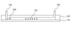
도 1을 참조하면, 유체용 센서의 챔버(101)는 하면을 이루는 기판(110)과 상면을 이루는 탑 플레이트(120)를 포함하는 본체부(111)를 포함한다. 상기 본체부(111)의 내부 공간은 유체샘플이 반응하는 부위인 반응부(130)에 해당한다.Referring to FIG. 1, a
유체샘플 내 포함되어 있는 타겟물질을 검출하기 위해, 상기 반응부(130)에 포함된 기판(110)의 일부 영역에는 타겟물질과 특이적으로 결합하는 리셉터(160)가 고정되어 있을 수 있다. 상기 유체 샘플은 생물학적 샘플일 수 있고, 예를 들어, 타액, 가래, 뇌척수액, 혈액, 혈청, 플라즈마, 소변, 생검 물질 등을 들 수 있으나 이에 한정되는 것은 아니다. 상기 타겟 물질은 단백질, 항체, 항원, DNA, RNA, 바이러스, 박테리아(Bacterial cell), 동물세포(Animal cell), 조직(Tissue) 등의 생체분자 또는 이에 의해 발생된 Toxin 등의 Bio products 등을 들 수 있으나, 이에 한정되는 것은 아니다. 또한, 상기 리셉터(160)는 타겟물질과 특이적으로 결합하는 것으로서 단백질, 항원, 항체, 효소, DNA, RNA, PNA(peptide nucleic acid, 인공 DNA), 세포, 및 후각신경(olfactory) 등을 들 수 있다.In order to detect the target material included in the fluid sample, a
상기 리셉터(160)는 기판(110) 상에 직접 결합될 수도 있고 다른 플레이트 상에 고정된 상태로 기판(110)에 놓여질 수도 있다. 이러한 기판(110)은 리셉터(160)와의 부착성이나 센서의 특성, 기계적 물성 등을 고려하여 적절히 선택될 수 있으며 통상 실리콘 기판, 플라스틱 기판, 반도체 기판, 유리 기판 등 당업계에 공지된 다양한 기판이 사용될 수 있으며 특별히 제한되지 않는다. 상기 기판(110)으로는 유체용 센서의 종류에 따라 압전물질이 사용될 수도 있다. 상기 압전물질은 기계적 신호의 인가시 전기적 특성이 변화되거나(압전효과), 전기적 신호의 인가시 기계적 신호가 생기는(역압전효과) 재료이다. 예를 들어, 니오브산 리튬(예; LiNbO3), 탄탈산 리튬(예; LiTaO3), 사붕소산 리튬(Li2B4O7), 티탄산바륨(BaTiO3), PbZrO3, PbTiO3, PZT, ZnO, GaAs, 석영(Quartz), 니오브산염 등을 들 수 있다.The
상기 탑 플레이트(120)는 상기 기판(110)과 다른 소재로 이루어질 수도 있으나, 동일한 소재로 이루어진 경우 고유 접촉각이 동일하게 되므로 기판(110)과 탑 플레이트(120)의 젖음 현상이 일정하게 이루어질 수 있다. 상기 탑 플레이트(120)는 또한, 유체샘플의 누수, 누출을 방지하기 위해 고무 가스켓, 고분자 수지 등의 소수성 소재로 이루어질 수 있으나, 친수성 소재가 사용되는 것을 제한하지 않는다. 경우에 따라, 상기 기판(110)과 탑 플레이트(120)는 동일한 소재로 이루어질 수 있으며, 이 경우 기판(110)의 고유 접촉각과 탑 플레이트(120)의 고유 접촉각 차이에 의해 젖음현상이 상이하게 나타나는 것을 방지할 수 있어서 기포의 형성을 방지하거나 최소화할 수 있다.The
이러한 기판(110)과 탑 플레이트(120)가 형성하는 폐쇄된 내부 공간은 반응부(130)가 된다. 상기 반응부(130)에 유체샘플을 유입 또는 유출하기 위해서 상기 탑 플레이트(120)의 일 단부에는 유체샘플이 유입되는 유입부(140)가 형성되어 있고, 탑 플레이트(120)의 타 단부에는 반응부(130)로부터 유체샘플이 유출되는 유출부(150)가 형성되어 있다.The closed inner space formed by the
상기 유입부(140)와 유출부(150)에는 필요에 따라 유체샘플의 이송 구동력을 제공하기 위한 펌프와 유체의 출입을 제어하기 위한 밸브(도시되지 않음)가 연결될 수 있다. 예를 들어, 유입부(140) 측에 양압펌프를 장착하고 유출부(150) 측에는 음압펌프를 연결할 수 있다. 이 경우 유입부(140) 측의 밸브를 열면 유입부(140)측의 양압펌프로부터 배출된 공기가 반응부(130) 내로 유입되고 이에 따른 압력에 의해 유체샘플이 이동할 수 있게 된다. 또한, 유출부(150) 측의 밸브를 열면 유출부(150)측의 음악펌프에 의해 반응부(130) 내 압력이 낮아지면서 유체샘플이 유츨부로 이동하게 된다.The
이하, 설명의 편의를 위하여 유입부(140)가 형성된 반응부(130) 영역을 영역(A)라고 하고, 유출부(150)가 형성된 반응부(130) 영역을 영역(B) 라고 한다.Hereinafter, for convenience of description, the
상기 영역(A)는 유입부(140)를 통해 유입된 유체샘플이 반응부(130)로 퍼져나가는 영역으로서 기판(110)에 유체샘플이 닿는 순간 기판(110) 표면을 따라 반응부(130)로 퍼져나가게 된다. 이 때, 유체샘플이 탑 플레이트(120)와 접촉하게 되는 데 유체가 탑 플레이트(120)와 완전히 밀착되지 않는 경우에는 젖지 않는 부분이 발생하여 기포가 발생하게 된다. 극히 적은 양의 기포는 문제가 되지 않을 수도 있지만 유체의 흐름 속에 뭉쳐져 큰 기포로 성장하게 되며 결국 시그널 노이즈로 작용한다.The region A is a region in which the fluid sample introduced through the
이와 관련하여 도 2 및 3에는 종래의 유체용 센서(10)의 투시 사시도 및 수직 단면도가 모식적으로 도시되어 있다. 이들 도면을 참조하면 반응부(13)가 직육면체 형태로 이루어져 있고, 유입부(14) 및 유출부(15)는 반응부(13)의 탑 플레이트(12) 상에 형성되어 있다. 이러한 형태의 유체용 센서에서 유입부(12)를 통해 유체가 주입되는 과정에서 유체(40)는 기판(11)과 먼저 접촉하고, 기판(11)과 탑 플레이트(12) 사이에 유체(40)가 접촉하지 못하게 되는 부분(50)이 발생하게 되는 바 이러한 부분(50)에서 기포가 발생될 수 있다.2 and 3 schematically illustrate a perspective perspective view and a vertical cross-sectional view of a
다시 도 1을 참조하면, 본 발명의 예에 따르면 이러한 기포 발생을 방지하기 위하여 상기 유입부(140)가 형성된 반응부(130) 영역(A)의 측단면(X)이 양의 각도(α)로 테이퍼된 기울기면(200)을 갖도록 이루어져 있다.Referring back to FIG. 1, according to an example of the present invention, in order to prevent such bubbles from occurring, the side cross-section X of the region A of the
이와 같은 구조를 이용하여 반응부(130) 내 기포의 발생이 최소화되거나 차단될 수 있다. 즉, 기판(110)에 닿은 용액이 기포 발생없이 탑 플레이트(120)의 모든 부분을 젖을 수 있도록 한다. 또한, 유체의 이동거리를 줄이고 유체의 이동시 가속력을 제공할 수 있다.By using such a structure, generation of bubbles in the
상기 기울기면(200)의 각도(α)는 기판(110)의 고유 접촉각보다 작게 형성될 수 있으며 기울기면(200)의 상면은 1-a와 같이 곡면으로 형성될 수도 있고, 1-b와 같이 직선면으로 형성될 수도 있다.The angle α of the
상기 고유 접촉각은 액체와 고체가 접촉하고 있을 때, 액체의 자유 표면이 고체 평면과 이루는 각도를 의미한다. 이러한 접촉각은 액체 분자 사이의 응집력과 액체/고체 벽 사이의 부착력으로 결정된다. 이에, 기판(110)의 종류에 따라 접촉각이 달라지게 된다.The intrinsic contact angle means the angle at which the free surface of the liquid forms a solid plane when the liquid and the solid are in contact. This contact angle is determined by the cohesion between the liquid molecules and the adhesion between the liquid / solid walls. Thus, the contact angle is changed according to the type of the
상기 기울기면(200)이 기판(110)의 고유 접촉각에 비해 작은 각도로 형성되는 경우 반응부(130)로 유입되는 유체가 액적을 만들지 않고 반응부(130) 내부로 퍼져나간다.When the
상기 반응부(130)의 수직 단면(Z)은 사각형이거나 양 측면이 내측으로 테이퍼된 곡면 또는 직선면으로 될 수 있다. 또한, 상기 기울기면이 형성된 반응부(130)의 수평 단면(Y) 역시 사각형이거나 양 측면이 내측으로 테이퍼된 곡면 또는 직선면으로 되어 있다. 이 때, 상기 내측으로 테이퍼된 각도(β)는 기판(110)의 고유 접촉각보다 작게 이루어질 수 있다. 이 경우에도 유체가 응집되지 않고 반응부(130) 내부로 용이하게 퍼져나갈 수 있으며 탑 플레이트(120)의 모든 부분을 젖게 함으로써 기포의 형성을 방지한다.The vertical section Z of the
상기 기울기면이 형성된 반응부(130)의 수평 단면(Y) 또는 반응부(130)의 수직단면(Z)은 예를 들어, 2-a와 같은 사각형일 수도 있고, 양 측면이 내측으로 테이퍼된 형태로서 2-b와 같은 삼각형, 2-c와 같은 사다리꼴, 2-d에서와 같은 반원형으로 이루어질 수 있다. 이 외에도 다양한 다각형이나 무정형일 수 있다.The horizontal section Y of the
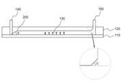
도 4에는 본 발명의 제 2 실시예에 따른 유체용 센서의 투시 사시도가 모식적으로 도시되어 있고, 도 5 및 6에는 본 발명의 제 3 실시예에 따른 유체용 센서의 투시 사시도와 단면도가 모식적으로 도시되어 있다. 설명의 편의를 위하여 도 4 내지 6에서 도 1에서와 동일하거나 대응되는 구성요소에 대해서는 동일한 부호를 부여하였다.4 is a perspective perspective view schematically showing a fluid sensor according to a second embodiment of the present invention, Figures 5 and 6 are a perspective perspective view and a cross-sectional view of a fluid sensor according to a third embodiment of the present invention Is shown as an example. For convenience of description, the same reference numerals are given to the same or corresponding elements as in FIG. 1 in FIGS. 4 to 6.
앞서 도 1에 도시된 본 발명의 제1 실시예에서는 반응부(130)의 수직 단면 및 수평단면이 모두 사각형(도 1 참조)이었으나, 도 4 및 5에 도시된 본 발명의 제2, 제3 실시예에 따른 유체용 센서는 반응부(130)가 수직 단면(Z)상 양 측면이 내측으로 테이퍼되고 수평 단면(Y)상 양 측면 역시 내측으로 테이퍼된 삼각형을 나타내고 있다. 이러한 구조에서는 반응부(130)로 유입된 유체샘플이 상대적으로 높게 위치하는 가운데 부분(131)으로 모이게 되어 유출부(150)로의 유출이 용이하게 된다. 이에 따라 설사 반응부(130) 내에 기포가 발생한다고 하더라도 쉽게 제거될 수 있다. 도 4에 도시된 제2 실시예(102)에서는 수직 단면(Z)상 양 측면이 내측으로 테이퍼된 직선면으로서 삼각형의 형태이나, 사다리꼴 등 다각형의 형태도 가능하다.In the first embodiment of the present invention shown in FIG. 1, the vertical and horizontal cross sections of the
또한, 도 5에 도시된 제3 실시예(103)에서는 수직 단면(Z)상 양 측면이 내측으로 테이퍼된 곡선면으로서 반원형의 형태가 된다. 도 5에서와 같이 반응부(130) 내면이 반구형의 터널과 같은 형태로 된 경우 모서리가 없기 때문에 기포의 발생을 방지할 뿐만 아니라 발생한 기포를 포집하지 않고 쉽게 유출될 수 있도록 한다.In addition, in the
이상 설명한 도 1 및 도 4 내지 6에서 유입부(140)는 유체샘플과 기판(110)의 접촉을 용이하게 하기 위해 기판(110)에 접하거나 근접하게 형성되어 있다. 반면에, 상기 유출부(150)는 유체샘플이 빠져나가기 용이한 구조를 가져야 하는 바, 탑 플레이트(120)에 근접하거나 탑 플레이트(120) 상에 형성된다.1 and 4 to 6 described above, the
이와 관련하여, 도 7에는 상기 유출부(150)가 변형된 구조를 개시하고 있다. 도 7을 참조하면, 유출부(150)가 형성된 반응부(130) 영역(B)의 측단면이 양의 각도(θ)로 테이퍼된 기울기면을 갖도록 형성되어 있다. 이와 같이 유출부(150)가 반응부(130)보다 높게 형성됨으로써 반응이나 유체샘플의 유동에 의해 발생된 기포가 쉽게 제거될 수 있다.
In this regard, FIG. 7 discloses a structure in which the
본 발명에서 예시적으로 설명하고 있는 유체용 센서는 센싱 방법에 있어서 특별히 제한되지 않는 바, 예를 표면 플라스몬 공명(SPR) 센서, QCM(Quartz Crystal Microbalance), 칸틸레버(Cantilever) 센서, 표면탄성파(SAW) 센서, BAW(bulk acoustic wave) 센서 등으로서 이용될 수 있다.The sensor for the fluid described in the present invention is not particularly limited in the sensing method, for example, surface plasmon resonance (SPR) sensor, QCM (Quartz Crystal Microbalance), cantilever sensor, surface acoustic wave (SAW) sensors, bulk acoustic wave (BAW) sensors, and the like.
상기 표면 플라스몬 공명(SPR) 센서는 금속 표면(금 또는 은) 또는 금속 나노입자 상의 시료의 흡착 정도를 측정하는 표준 계측 원리로 이용하는 센서로서 표면 플라스몬 공명(Surface plasmon resonance)은 평평한 표면에 입사한 빛에 의해 들뜬 상태가 된 표면 플라스몬의 상태를 가리킨다.The surface plasmon resonance (SPR) sensor is a sensor used as a standard measurement principle for measuring the degree of adsorption of a sample on a metal surface (gold or silver) or metal nanoparticles, and surface plasmon resonance is incident on a flat surface. Refers to the state of the surface plasmon excited by a light.
상기 QCM(Quartz Crystal Microbalance) 센서는 커플링제를 코팅한 수정 결정(quartz crystal)에 리셉터를 고정화한 후 이에 특이적인 측정대상물질과 반응시키고, 반응 전과 후의 주파수 변화량을 측정함으로써 타겟물질의 농도를 측정하는 센서이다.The QCM (Quartz Crystal Microbalance) sensor measures the concentration of the target material by immobilizing the receptor in a quartz crystal coated with a coupling agent and reacting with the specific target material, and measuring the frequency change before and after the reaction. It is a sensor.
상기 칸틸레버(Cantilever) 센서는 캔틸레버 표면에 분자가 흡착되면 공명진동수뿐만 아니라 스트레스의 변화에 의하여 캔틸레버가 휘어지는 현상을 이용하는 센서이다.The cantilever sensor is a sensor using a phenomenon in which the cantilever is bent due to a change in stress as well as a resonance frequency when molecules are adsorbed on the surface of the cantilever.
상기 표면탄성파(SAW) 센서와 BAW(bulk acoustic wave) 센서는 고체 내에서 탄성파로 전달되는 음향파를 이용하여 대상물질의 존부 또는 물성 등을 센싱하는 장치이다. 이러한 음향파는 (Acoustic Wave)는 전자파가 아니라 외부의 열적, 기계적, 전기적 힘에 의한 입자들의 운동으로부터 발생하는 기계적인 파동으로서, 진동에너지의 대부분이 매질의 표면에 집중된다. 벌크 탄성파(BAW)는 탄성체 기판의 벌크(전체)에 전파되는 것이고, 표면 탄성파(SAW)는 기판의 표면에 따라 전파되는 파장이다.
The surface acoustic wave (SAW) sensor and the bulk acoustic wave (BAW) sensor are devices for sensing the presence or property of a target material by using acoustic waves transmitted as elastic waves in a solid. This acoustic wave is not a electromagnetic wave but a mechanical wave generated from the movement of particles by external thermal, mechanical and electrical forces, and most of the vibration energy is concentrated on the surface of the medium. The bulk acoustic wave BAW is propagated to the bulk (whole) of the elastic substrate, and the surface acoustic wave SAW is a wavelength propagated along the surface of the substrate.
[실시예 1]Example 1
도 5에서와 같은 형태의 SAW 바이오센서를 제작한다. 기판으로는 BSA(Bovine serum albumin) 가 코팅된 SiO2 기판을 사용한다. SiO2 기판의 표면에는 APTES로 된 SAM 층을 형성한다. 기울기면의 각도(알파)는 동 기판의 고유 접촉각인 59도 (참조: Journal of General Microbiology(1987),133,3199-3206) 보다 낮은 40도 내외의 갖도록 한다. 탑 플레이트는 실리콘으로 제작한다. 기판은 폭이 2.5 mm, 너비가 8.4 mm이며, 높이가 1 mm이다. 유입부는 샘플이 기판에 바로 닿을 수 있도록 기판에 용액이 바로 가도록 형성하고 유출부는 상단에 형성한다. 유입부와 유출부는 φ 0.7 mm의 크기로 형성한다. 상기 기판 상에는 SAW 센서를 이루기 위한 IDT 전극쌍이 형성되어 있다. 탑 플레이트의 윗면은 튜브와 연결될 수 있도록 형성하여 펌프 및 밸브가 연결된다.A SAW biosensor of the same type as in FIG. 5 is manufactured. As a substrate, a SiO2 substrate coated with Bovine serum albumin (BSA) is used. The surface of the SiO2 substrate forms a SAM layer of APTES. The angle of the inclined plane (alpha) should be around 40 degrees below the intrinsic contact angle of the substrate, 59 degrees (seeJournal of General Microbiology (1987),133, 3199-3206). The top plate is made of silicon. The substrate is 2.5 mm wide, 8.4 mm wide and 1 mm high. The inlet is formed so that the solution goes directly to the substrate so that the sample can directly contact the substrate and the outlet is formed at the top. The inlet and outlet are formed with a diameter of 0.7 mm. An IDT electrode pair for forming a SAW sensor is formed on the substrate. The upper surface of the top plate is formed to be connected to the tube to connect the pump and the valve.
[실험예][Experimental Example]
도 1과 같은 형태의 기존 SAW 바이오센서와 상기 실시예 1에 따른 바이오센서에 각각 동일한 액체샘플인 1x PBS를 실온에서 1 ml/min의 속도로 유입부를 통해 주입한다. 유출부로 배출되도록 하고, 기포의 발생 빈도를 육안으로 확인하였으며 반응시 주파수 변화(Hz)를 측정하여 노이즈 발생 빈도를 측정하였다.
1x PBS, the same liquid sample, is injected into the existing SAW biosensor having the same shape as that of FIG. 1 through the inlet at a rate of 1 ml / min at room temperature. It was discharged to the outlet, and the frequency of bubbles was visually confirmed, and the frequency of noise was measured by measuring the frequency change (Hz) during the reaction.
[표 1] [Table 1]

반응 결과, 실시예 1의 SAW 바이오센서는 탑 플레이트의 모든 부분이 고루 젖음으로써 기포가 발생하지 않아 기포에 의한 노이즈 발생이 전혀 없었다. 이는 기존의 노이즈 비율 30%에 비해 획기적으로 좋은 결과이다.As a result of the reaction, in the SAW biosensor of Example 1, all parts of the top plate were evenly wetted so that no bubbles were generated and no noise was generated by bubbles. This is a significantly better result than the existing noise ratio of 30%.
본 발명이 속한 분야에서 통상의 지식을 가진 자라면 상기 내용을 바탕으로 본 발명의 범주 내에서 다양한 응용 및 변형을 행하는 것이 가능할 것이다.Those skilled in the art will appreciate that various modifications, additions and substitutions are possible, without departing from the scope and spirit of the invention as disclosed in the accompanying claims.
Claims (11)
Translated fromKorean상기 유입부가 형성된 반응부 영역(A)의 측단면은 양의 각도(α)로 테이퍼된 기울기면을 갖는, 유체용 센서.A main body portion including a substrate forming a lower surface and a top plate constituting an upper surface, a reaction part to which a fluid sample reacts as an inner space of the main body part, an inlet part located at one side of the top plate and an inflow part of the fluid sample to the reaction part, and Located on the other side of the top plate and includes an outlet for outflow of the fluid sample from the reaction,
The side cross section of the reaction zone (A) in which the inlet is formed has a sloped surface tapered at a positive angle (α).
상기 기울기면의 각도(α)는 기판의 고유 접촉각보다 작은, 유체용 센서.The method of claim 1,
The angle α of the inclined plane is smaller than the intrinsic contact angle of the substrate.
상기 기울기면은 곡면 또는 직선면으로 된, 유체용 센서.The method of claim 2,
The inclined surface is a curved surface or a straight surface.
상기 반응부의 수직 단면은 사각형이거나 양 측면이 내측으로 테이퍼된 곡면 또는 직선면으로 된, 유체용 센서.The method of claim 1,
The vertical cross-section of the reaction unit is a square or a curved surface or a straight surface both sides tapered inwards, the sensor for a fluid.
상기 기울기면이 형성된 반응부의 수평 단면은 사각형이거나 양 측면이 내측으로 테이퍼된 곡면 또는 직선면으로 된, 유체용 센서.The method of claim 1,
The horizontal cross section of the reaction part in which the inclined surface is formed is a quadrangle or a curved or straight surface in which both sides are tapered inward.
상기 내측으로 테이퍼된 각도(β)는 기판의 고유 접촉각보다 작은, 유체용 센서.The method according to claim 4 or 5,
The inwardly tapered angle β is less than the intrinsic contact angle of the substrate.
상기 반응부 내 기판의 적어도 일부에는 유체샘플 내 타겟 물질과 특이적으로 반응하는 리셉터가 고정되어 있는, 유체용 센서.The method of claim 1,
At least a portion of the substrate in the reaction portion is a fluid sensor, the receptor which is specifically reacted with the target material in the fluid sample is fixed.
상기 유입부의 하단은 기판에 접하거나 근접하게 형성된, 유체용 센서.The method of claim 1,
A lower end of the inlet is formed in contact with or in proximity to the substrate.
상기 유출부의 하단부는 탑 플레이트 상에 형성된, 유체용 센서.The method of claim 1,
And a lower end of the outlet portion is formed on the top plate.
상기 유출부가 형성된 반응부 영역(B)의 측단면은 양의 각도(θ)로 테이퍼된 기울기면을 갖는, 유체용 센서.The method of claim 1,
The side cross section of the reaction part region (B) in which the outlet part is formed has an inclined surface tapered at a positive angle θ.
표면플라스몬 공명(SPR) 센서, QCM(Quartz Crystal Microbalance), 칸틸레버(Cantilever) 센서, 표면탄성파(SAW) 센서, BAW(bulk acoustic wave) 센서로 이루어진 군에서 선택되는 센서인, 유체용 센서.The method of claim 1,
A sensor for fluids, which is a sensor selected from the group consisting of surface plasmon resonance (SPR) sensors, quartz crystal microbalance (QCM), cantilever sensors, surface acoustic wave (SAW) sensors, and bulk acoustic wave (BAW) sensors.
Priority Applications (2)
| Application Number | Priority Date | Filing Date | Title |
|---|---|---|---|
| KR1020100067146AKR20120006591A (en) | 2010-07-13 | 2010-07-13 | Sensor for fluids with no bubbles |
| US13/037,415US8968674B2 (en) | 2010-07-13 | 2011-03-01 | Fluid sensor preventing generation of air bubbles |
Applications Claiming Priority (1)
| Application Number | Priority Date | Filing Date | Title |
|---|---|---|---|
| KR1020100067146AKR20120006591A (en) | 2010-07-13 | 2010-07-13 | Sensor for fluids with no bubbles |
Publications (1)
| Publication Number | Publication Date |
|---|---|
| KR20120006591Atrue KR20120006591A (en) | 2012-01-19 |
Family
ID=45467301
Family Applications (1)
| Application Number | Title | Priority Date | Filing Date |
|---|---|---|---|
| KR1020100067146AWithdrawnKR20120006591A (en) | 2010-07-13 | 2010-07-13 | Sensor for fluids with no bubbles |
Country Status (2)
| Country | Link |
|---|---|
| US (1) | US8968674B2 (en) |
| KR (1) | KR20120006591A (en) |
Cited By (1)
| Publication number | Priority date | Publication date | Assignee | Title |
|---|---|---|---|---|
| WO2024150886A1 (en)* | 2023-01-12 | 2024-07-18 | 주식회사 큐빅케이 | Optical analyzer and bioreactor comprising same |
Families Citing this family (5)
| Publication number | Priority date | Publication date | Assignee | Title |
|---|---|---|---|---|
| GB201211557D0 (en)* | 2012-06-29 | 2012-08-15 | Ibm | Microfluidic surface processing device and method |
| JP2014097485A (en)* | 2012-10-18 | 2014-05-29 | Enplas Corp | Liquid handling apparatus |
| US11065620B2 (en) | 2016-07-12 | 2021-07-20 | EMULATE, Inc. | Removing bubbles in a microfluidic device |
| CN111220767A (en)* | 2018-11-23 | 2020-06-02 | 京元电子股份有限公司 | Elastic buffer seat for testing biochip, testing module and testing equipment thereof |
| US10948400B1 (en) | 2019-09-17 | 2021-03-16 | General Electric Company | Sensor probe assembly and method of forming |
Family Cites Families (11)
| Publication number | Priority date | Publication date | Assignee | Title |
|---|---|---|---|---|
| US5234813A (en)* | 1989-05-17 | 1993-08-10 | Actimed Laboratories, Inc. | Method and device for metering of fluid samples and detection of analytes therein |
| US5922604A (en)* | 1997-06-05 | 1999-07-13 | Gene Tec Corporation | Thin reaction chambers for containing and handling liquid microvolumes |
| US6576478B1 (en)* | 1998-07-14 | 2003-06-10 | Zyomyx, Inc. | Microdevices for high-throughput screening of biomolecules |
| US20020006664A1 (en)* | 1999-09-17 | 2002-01-17 | Sabatini David M. | Arrayed transfection method and uses related thereto |
| CA2555060C (en)* | 2004-02-20 | 2014-12-23 | Research Foundation Of The State University Of New York | Method and device for manipulating liquids in microfluidic systems |
| DE102004027422A1 (en)* | 2004-06-04 | 2005-12-29 | Boehringer Ingelheim Microparts Gmbh | Device for receiving blood and separating blood components |
| JP2007111672A (en) | 2005-10-24 | 2007-05-10 | Kyocera Corp | Micro chemical chip |
| US7695956B2 (en)* | 2006-01-12 | 2010-04-13 | Biocept, Inc. | Device for cell separation and analysis and method of using |
| JP5062399B2 (en) | 2007-02-19 | 2012-10-31 | セイコーインスツル株式会社 | Microchannels and microreactors |
| JP2008298598A (en) | 2007-05-31 | 2008-12-11 | Canon Inc | Microfluidic device, method of using the same, and method of manufacturing the same |
| JP2009236555A (en) | 2008-03-26 | 2009-10-15 | Shimadzu Corp | Fluid device and manufacturing method thereof |
- 2010
- 2010-07-13KRKR1020100067146Apatent/KR20120006591A/ennot_activeWithdrawn
- 2011
- 2011-03-01USUS13/037,415patent/US8968674B2/enactiveActive
Cited By (1)
| Publication number | Priority date | Publication date | Assignee | Title |
|---|---|---|---|---|
| WO2024150886A1 (en)* | 2023-01-12 | 2024-07-18 | 주식회사 큐빅케이 | Optical analyzer and bioreactor comprising same |
Also Published As
| Publication number | Publication date |
|---|---|
| US8968674B2 (en) | 2015-03-03 |
| US20120015451A1 (en) | 2012-01-19 |
Similar Documents
| Publication | Publication Date | Title |
|---|---|---|
| Alvarez et al. | Microcantilever-based platforms as biosensing tools | |
| Bunde et al. | Piezoelectric quartz crystal biosensors | |
| US7935191B2 (en) | Controlling accumulation of select adsorbers on a piezoelectric cantilever sensor | |
| Čavić et al. | Acoustic waves and the study of biochemical macromolecules and cells at the sensor–liquid interface | |
| JP6882280B2 (en) | Acoustic resonator devices, as well as manufacturing methods that provide airtightness and surface functionalization. | |
| KR20120006591A (en) | Sensor for fluids with no bubbles | |
| US11444595B2 (en) | Acoustic resonator device with controlled placement of functionalization material | |
| Ricciardi et al. | Integration of microfluidic and cantilever technology for biosensing application in liquid environment | |
| JP6898344B2 (en) | BAW sensor fluid system with increased dynamic measurement range | |
| WO2019192125A1 (en) | Biosensor based on surface acoustic wave mode and test method thereof | |
| JP5487200B2 (en) | Surface plasmon resonance sensing device and method integrated with shear vertical surface acoustic wave | |
| KR20140097115A (en) | Biocoated piezoelectric biosensor platform for point-of-care diagnostic use | |
| KR101218987B1 (en) | Biochip and manufacturing method thereof and method for detecting analyzed material using the biochip | |
| JP2023175818A (en) | Bioactive coating for surface acoustic wave sensor | |
| US12332216B2 (en) | Sensor with droplet retaining structure | |
| Agarwal et al. | Detection of heart-type fatty acid-binding protein (h-FABP) using piezoresistive polymer microcantilevers functionalized by a dry method | |
| Saad et al. | Quartz crystal microbalance for bacteria application review | |
| US20220146510A1 (en) | Methods of surface modification of silicones for specific target and high efficiency binding | |
| US8277750B2 (en) | Detector for chemical sensor device and use thereof | |
| US10329396B2 (en) | Process for immobilizing one or more receptor biomolecules on one or more solid surfaces | |
| WO2008019694A2 (en) | Bio surface acoustic wave (saw) resonator design for detection of a target analyte | |
| WO2016060674A1 (en) | A system for obtaining biomlecular measures based on piezoelectric technology | |
| CN104406881B (en) | A kind of piezoelectric sound wave biology sensor based on micro-nano structure | |
| Kato et al. | Reusable high-frequency electrodeless QCM biosensor with a bare quartz resonator embedded in a silicon microchannel | |
| CN119125281A (en) | Field effect transistor component machine usage method, biosensor detection device |
Legal Events
| Date | Code | Title | Description |
|---|---|---|---|
| PA0109 | Patent application | St.27 status event code:A-0-1-A10-A12-nap-PA0109 | |
| PG1501 | Laying open of application | St.27 status event code:A-1-1-Q10-Q12-nap-PG1501 | |
| R17-X000 | Change to representative recorded | St.27 status event code:A-3-3-R10-R17-oth-X000 | |
| R18-X000 | Changes to party contact information recorded | St.27 status event code:A-3-3-R10-R18-oth-X000 | |
| PC1203 | Withdrawal of no request for examination | St.27 status event code:N-1-6-B10-B12-nap-PC1203 | |
| WITN | Application deemed withdrawn, e.g. because no request for examination was filed or no examination fee was paid |