KR20120005264A - A compressed air fan - Google Patents
A compressed air fanDownload PDFInfo
- Publication number
- KR20120005264A KR20120005264AKR1020100065916AKR20100065916AKR20120005264AKR 20120005264 AKR20120005264 AKR 20120005264AKR 1020100065916 AKR1020100065916 AKR 1020100065916AKR 20100065916 AKR20100065916 AKR 20100065916AKR 20120005264 AKR20120005264 AKR 20120005264A
- Authority
- KR
- South Korea
- Prior art keywords
- air
- main body
- fan
- discharge hole
- discharged
- Prior art date
- Legal status (The legal status is an assumption and is not a legal conclusion. Google has not performed a legal analysis and makes no representation as to the accuracy of the status listed.)
- Ceased
Links
- 238000007664blowingMethods0.000claimsabstractdescription24
- 230000003321amplificationEffects0.000claimsdescription6
- 238000003199nucleic acid amplification methodMethods0.000claimsdescription6
- 238000000034methodMethods0.000claims6
- 238000007599dischargingMethods0.000abstract1
- 239000003570airSubstances0.000description93
- 238000009434installationMethods0.000description3
- 239000012080ambient airSubstances0.000description2
- 238000010586diagramMethods0.000description2
- 238000009423ventilationMethods0.000description2
- 208000027418Wounds and injuryDiseases0.000description1
- 230000006378damageEffects0.000description1
- 208000014674injuryDiseases0.000description1
- 238000013021overheatingMethods0.000description1
Images


Classifications
- F—MECHANICAL ENGINEERING; LIGHTING; HEATING; WEAPONS; BLASTING
- F04—POSITIVE - DISPLACEMENT MACHINES FOR LIQUIDS; PUMPS FOR LIQUIDS OR ELASTIC FLUIDS
- F04D—NON-POSITIVE-DISPLACEMENT PUMPS
- F04D25/00—Pumping installations or systems
- F04D25/02—Units comprising pumps and their driving means
- F04D25/08—Units comprising pumps and their driving means the working fluid being air, e.g. for ventilation
- F—MECHANICAL ENGINEERING; LIGHTING; HEATING; WEAPONS; BLASTING
- F04—POSITIVE - DISPLACEMENT MACHINES FOR LIQUIDS; PUMPS FOR LIQUIDS OR ELASTIC FLUIDS
- F04D—NON-POSITIVE-DISPLACEMENT PUMPS
- F04D29/00—Details, component parts, or accessories
- F04D29/002—Details, component parts, or accessories especially adapted for elastic fluid pumps
- F—MECHANICAL ENGINEERING; LIGHTING; HEATING; WEAPONS; BLASTING
- F04—POSITIVE - DISPLACEMENT MACHINES FOR LIQUIDS; PUMPS FOR LIQUIDS OR ELASTIC FLUIDS
- F04D—NON-POSITIVE-DISPLACEMENT PUMPS
- F04D29/00—Details, component parts, or accessories
- F04D29/40—Casings; Connections of working fluid
- F04D29/403—Casings; Connections of working fluid especially adapted for elastic fluid pumps
- F—MECHANICAL ENGINEERING; LIGHTING; HEATING; WEAPONS; BLASTING
- F04—POSITIVE - DISPLACEMENT MACHINES FOR LIQUIDS; PUMPS FOR LIQUIDS OR ELASTIC FLUIDS
- F04D—NON-POSITIVE-DISPLACEMENT PUMPS
- F04D29/00—Details, component parts, or accessories
- F04D29/40—Casings; Connections of working fluid
- F04D29/52—Casings; Connections of working fluid for axial pumps
- F04D29/54—Fluid-guiding means, e.g. diffusers
- F04D29/541—Specially adapted for elastic fluid pumps
- H—ELECTRICITY
- H02—GENERATION; CONVERSION OR DISTRIBUTION OF ELECTRIC POWER
- H02K—DYNAMO-ELECTRIC MACHINES
- H02K9/00—Arrangements for cooling or ventilating
- H02K9/02—Arrangements for cooling or ventilating by ambient air flowing through the machine
- H02K9/04—Arrangements for cooling or ventilating by ambient air flowing through the machine having means for generating a flow of cooling medium
- F—MECHANICAL ENGINEERING; LIGHTING; HEATING; WEAPONS; BLASTING
- F05—INDEXING SCHEMES RELATING TO ENGINES OR PUMPS IN VARIOUS SUBCLASSES OF CLASSES F01-F04
- F05D—INDEXING SCHEME FOR ASPECTS RELATING TO NON-POSITIVE-DISPLACEMENT MACHINES OR ENGINES, GAS-TURBINES OR JET-PROPULSION PLANTS
- F05D2210/00—Working fluids
- F05D2210/10—Kind or type
- F05D2210/12—Kind or type gaseous, i.e. compressible
- F—MECHANICAL ENGINEERING; LIGHTING; HEATING; WEAPONS; BLASTING
- F05—INDEXING SCHEMES RELATING TO ENGINES OR PUMPS IN VARIOUS SUBCLASSES OF CLASSES F01-F04
- F05D—INDEXING SCHEME FOR ASPECTS RELATING TO NON-POSITIVE-DISPLACEMENT MACHINES OR ENGINES, GAS-TURBINES OR JET-PROPULSION PLANTS
- F05D2260/00—Function
- F05D2260/60—Fluid transfer
- Y—GENERAL TAGGING OF NEW TECHNOLOGICAL DEVELOPMENTS; GENERAL TAGGING OF CROSS-SECTIONAL TECHNOLOGIES SPANNING OVER SEVERAL SECTIONS OF THE IPC; TECHNICAL SUBJECTS COVERED BY FORMER USPC CROSS-REFERENCE ART COLLECTIONS [XRACs] AND DIGESTS
- Y10—TECHNICAL SUBJECTS COVERED BY FORMER USPC
- Y10S—TECHNICAL SUBJECTS COVERED BY FORMER USPC CROSS-REFERENCE ART COLLECTIONS [XRACs] AND DIGESTS
- Y10S415/00—Rotary kinetic fluid motors or pumps
- Y—GENERAL TAGGING OF NEW TECHNOLOGICAL DEVELOPMENTS; GENERAL TAGGING OF CROSS-SECTIONAL TECHNOLOGIES SPANNING OVER SEVERAL SECTIONS OF THE IPC; TECHNICAL SUBJECTS COVERED BY FORMER USPC CROSS-REFERENCE ART COLLECTIONS [XRACs] AND DIGESTS
- Y10—TECHNICAL SUBJECTS COVERED BY FORMER USPC
- Y10S—TECHNICAL SUBJECTS COVERED BY FORMER USPC CROSS-REFERENCE ART COLLECTIONS [XRACs] AND DIGESTS
- Y10S417/00—Pumps
Landscapes
- Engineering & Computer Science (AREA)
- Mechanical Engineering (AREA)
- General Engineering & Computer Science (AREA)
- Power Engineering (AREA)
- Structures Of Non-Positive Displacement Pumps (AREA)
Abstract
Translated fromKoreanDescription
Translated fromKorean본 발명은 선풍기에 관한 것으로, 보다 상세하게는 증폭된 공기를 이용하여 안전하게 사용할 수 있는 압축 공기를 이용한 선풍기에 관한 것이다.The present invention relates to a fan, and more particularly to a fan using compressed air that can be safely used using amplified air.
일반적으로 선풍기는 모터에 의해서 회전되는 팬을 이용하여 바람을 일으키는 장치이며, 주로 더위를 식히거나 환기를 시키는데 사용된다. 이러한 선풍기는 스탠드식과 입설식이 있다. 스탠드식은 베이스부와, 수직지주와, 구동부와, 팬으로 이루어지며, 상기 팬은 수평방향으로 바람을 송풍하고, 기종에 따라서 구동부가 좌, 우 회동작동되어 바람의 송풍 범위를 넓게 할 수 있다. 입설식의 경우 수직으로 설치된 비교적 긴 블로워와, 상기 블로워를 감싸고 있는 케이스와, 상기 블로워를 구동시키고 케이스를 좌, 우 회전시키기 위한 구동부로 이루어진다.
Generally, a fan is a device that generates wind by using a fan rotated by a motor, and is mainly used to cool or ventilate the heat. These fans are stand type and standing type. The stand type includes a base part, a vertical support, a driving part, and a fan, wherein the fan blows wind in a horizontal direction, and the driving part rotates left and right according to the model to widen the blowing range of the wind. In case of standing type, it consists of a relatively long blower installed vertically, a case surrounding the blower, and a driving unit for driving the blower and rotating the case left and right.
전술한 선풍기와 관련된 선행기술이 한국공개특허공보 제1997-16152호(1997.04.28) "선풍기"에 개시되어 있다. 상기 선행기술은 소정의 통기공을 갖는 안내공간부와 이 안내공간부의 중앙에 형성된 설치홈부와 그 후방에 흡입구가 형성된 본체와, 이 본체의 내측에 설치되는 구동수단을 구비한 송풍팬과, 상기 구동수단의 구동축 단부와 연동되게 설치되는 복수의 기어로 구성된 구동기어군과, 상기 구동기어군에 의해 안내공간부의 내측에서 제자리 회동하면서 본체의 전방으로 바람을 가변시키는 풍향가이드로 구성되는 것을 특징으로 한다.
Prior art related to the aforementioned fan is disclosed in Korean Patent Laid-Open Publication No. 1997-16152 (April 28, 1997) "Fan". The prior art is a blower fan having a guide space portion having a predetermined ventilation hole, the installation groove portion formed in the center of the guide space portion, a main body having a suction port formed therein, and a driving means installed inside the main body; A drive gear group comprising a plurality of gears installed in association with the drive shaft end of the drive means, and the wind direction guide for varying the wind to the front of the main body while rotating in place in the guide space by the drive gear group.
상기 선행기술은 회전날개 전방의 풍향가이드를 회전시켜 풍향을 가변시킴으로서 선풍기의 설치 공간을 최소화시키는 동시에 풍향을 가변시키는데 소요되는 구동력을 극소화시킬 수 있는 이점이 있다. 다만, 송풍팬이 어린 아이 등의 손가락이 닿을 수 있는 곳에 있어 어린 아이 등이 손가락을 넣을 경우 다칠 위험이 있고, 송풍팬을 통해서 외부로 배출되는 공기량이 풍향가이드의 구조적 특성상 제한되는 단점이 있다.The prior art has the advantage of minimizing the installation space of the fan by minimizing the installation space of the fan by rotating the wind direction guide in front of the rotary blade has the advantage of minimizing the driving force. However, there is a risk that the blowing fan is in a place where a finger such as a young child can touch, the risk of injury if the young child put a finger, and the amount of air discharged to the outside through the blowing fan is limited due to the structural characteristics of the wind direction guide.
본 발명은 상술한 바와 같은 문제점을 해결하기 위해 안출 된 것으로, 본 발명의 일 실시예는 안전하면서도 바람의 양을 증폭시켜 시원함을 증가시킨 압축 공기를 이용한 선풍기와 관련된다.The present invention has been made to solve the problems described above, an embodiment of the present invention relates to a fan using compressed air that is safe while amplifying the amount of wind to increase the coolness.
본 발명의 바람직한 일 실시예는 에어유입홀과 에어배출홀이 형성된 본체와, 이 본체에 설치되며 에어유입홀을 통하여 흡입된 공기가 에어배출홀을 통하여 배출되도록 하는 송풍수단과, 에어배출홀과 연통 되도록 본체에 설치되며 일측에 형성된 노즐홈에 의해서 에어배출홀을 통해서 배출되는 공기가 증폭되도록 하는 에어증폭부를 포함하여 이루어지는 것을 특징으로 하는 압축 공기를 이용한 선풍기를 제공한다.According to an embodiment of the present invention, an air inlet hole and an air discharge hole are formed in the main body, blower means installed in the main body so that the air sucked through the air inlet hole is discharged through the air discharge hole, and the air discharge hole; It is installed on the main body to communicate with the present invention provides a fan using a compressed air comprising an air amplifier for amplifying the air discharged through the air discharge hole by the nozzle groove formed on one side.
상술한 바와 같은 본 발명의 일 실시예에 따르면 첫째, 안전하면서도 바람의 양을 증폭시켜 시원함을 증가시킨 압축 공기를 이용한 선풍기를 제공할 수 있다.According to one embodiment of the present invention as described above, first, it is possible to provide a fan using compressed air that increases safety by amplifying the amount of wind while being safe.
둘째, 송풍수단에 의해서 주위 공기를 끌어들이고 이 주위 공기가 송풍수단을 거쳐 본체의 외부로 배출되므로 송풍수단의 과열을 방지하여 선풍기의 내구성을 향상시킬 수 있다.Second, the air is drawn by the blowing means, and the surrounding air is discharged to the outside of the main body through the blowing means, thereby preventing overheating of the blowing means, thereby improving durability of the fan.
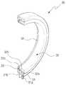
도 1 은 본 발명의 일 실시예에 따른 압축 공기를 이용한 선풍기를 도시한 사시도,
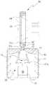
도 2 는 도 1에 도시된 압축 공기를 이용한 선풍기의 정단면도,
도 3 은 도 1에 도시된 압축 공기를 이용한 선풍기에 채용된 에어증폭부의 절개 사시도,
도 4 는 본 발명의 일 실시예에 따른 압축 공기를 이용한 선풍기의 사용 상태도,
도 5 는 도 2에 도시된 압축 공기를 이용한 선풍기에 채용된 송풍수단의 변형 실시예이다.1 is a perspective view showing a fan using compressed air according to an embodiment of the present invention,
2 is a front sectional view of the fan using the compressed air shown in FIG.
3 is a cutaway perspective view of an air amplification unit employed in a fan using the compressed air shown in FIG. 1;
4 is a state diagram using a fan using compressed air according to an embodiment of the present invention,
5 is a modified embodiment of the blowing means employed in the fan using the compressed air shown in FIG.
도 1 은 본 발명의 일 실시예에 따른 압축 공기를 이용한 선풍기를 도시한 사시도이고, 도 2 는 도 1에 도시된 압축 공기를 이용한 선풍기의 정단면도이고, 도 3 은 도 1에 도시된 압축 공기를 이용한 선풍기에 채용된 에어증폭부의 절개 사시도이고, 도 4 는 본 발명의 일 실시예에 따른 압축 공기를 이용한 선풍기의 사용 상태도이고, 도 5 는 도 2에 도시된 압축 공기를 이용한 선풍기에 채용된 송풍수단의 변형 실시예이다.
1 is a perspective view showing a fan using compressed air according to an embodiment of the present invention, Figure 2 is a front sectional view of the fan using the compressed air shown in Figure 1, Figure 3 is a compressed air shown in Figure 1 4 is a cutaway perspective view of an air amplifier employed in a fan, and FIG. 4 is a state diagram of a fan using compressed air according to an embodiment of the present invention, and FIG. 5 is a fan of the compressed air shown in FIG. A modified embodiment of the blowing means.
본 발명의 바람직한 실시예에 따른 압축 공기를 이용한 선풍기(1)는 본체(10), 송풍수단(20), 에어증폭부(30)를 포함한다.
The
본체(10)는 도 1에 도시된 바와 같이 원형 등 다양한 형태로 변형될 수 있고, 이 본체(10)의 측벽에는 다수의 에어유입홀(11)이 형성되고, 그 상측에는 도 2에 도시된 바와 같이 에어배출홀(12)이 형성된다. 상기 에어배출홀(12)에는 후술할 에어증폭부(30)가 바람직하게는 나사 결합 되도록 나사산이 형성된다. 또한, 본체(10)의 내측에는 후술할 송풍수단(20)에 의해서 흡입되는 공기가 에어배출홀(12)로 유실되지 않고 전달되도록 도 2에 도시된 바와 같이 에어유입관(13)과 에어가이드부(14)가 형성된다. 상기 에어유입관(13)과 에어가이드부(14)는 상측으로 갈수록 경사지도록 형성되는 것이 바람직하다. 상기 에어유입관(13)는 송풍수단(20)에 의해서 유입된 공기가 에어배출홀(12)로 압축 배출되도록 하는 역할도 한다.
The
송풍수단(20)은 도 2에 도시된 바와 같이 본체(10)의 내부에 설치되며 외부의 공기를 에어유입홀(11)을 통해서 흡입한 후 에어배출홀(12)로 배출되도록 하는 역할을 한다. 상기 송풍수단(20)은 도 2에 도시된 바와 같이 본체(10)의 바닥에 설치되는 모터(21)와, 이 모터(21)에 연결되어 일체로 회전되는 회전팬(21a)으로 구성된다. 또한, 이 송풍수단(20)은 도 5에 도시된 바와 같이 본체(10)의 바닥에 설치되며 에어흡입홀을 통해서 공기를 흡입하는 압축기(22)와, 일측은 상기 압축기(22)에 연결되고 타측은 에어배출홀(12)에 연결되어 압축기(22)에서 흡입된 공기가 에어배출홀(12)로 배출되도록 하는 관 형태의 송풍가이드(22a)로 구성될 수 있다. 송풍수단(20)은 전술한 형태 이외에 공지된 다른 형태의 공기 흡입 수단으로 대체될 수 있다.
The blowing
에어증폭부(30)는 도 1 및 2에 도시된 바와 같이 본체(10)의 상측에 설치되며 본체(10)의 에어배출홀(12)을 통해서 배출되는 고압의 공기가 주위의 공기를 끌어들여 바람의 양을 증폭시켜 사용자가 시원함을 느끼게 하도록 하는 역할을 한다. 상기 에어증폭부(30)는 도 2에 도시된 바와 같이 하측에 형성된 지지로드(31a)에 의해서 본체(10)의 에어배출홀(12)에 탈착 가능하도록 바람직하게는 나사 결합 되는 증폭부베이스(31)와, 상기 증폭부베이스(31)의 내주면에 바람직하게는 끼워 맞춤 또는 나사 결합 되어 노즐홈(33)을 형성하는 간격형성부재(32)로 구성된다.
The
상기 증폭부베이스(31)의 하측에는 도 3에 도시된 바와 같이 본체(10)의 에어배출홀(12)과 연통 되는 에어유입홈(31b)이 형성되고, 이 에어유입홈(31b)은 상기 노즐홈(33)과 연통 되며 많은 양의 공기가 유입되도록 노즐홈(33)보다 넓게 형성된다. 또한, 증폭부베이스(31)의 상측에는 도 3에 도시된 바와 같이 경사면(31c)이 형성되고, 이 경사면(31c)은 후술할 간격형성부재경사면(32b)과 함께 병목부(34)를 형성한다. 이 병목부(34)는 통과되는 공기의 유속을 증가시켜 단위 시간당 많은 양의 공기가 통과될 수 있도록 하는 역할을 한다.
An
상기 간격형성부재(32)의 외주면에는 도 2에 도시된 바와 같이 증폭부베이스(31)의 에어유입홈(31b)과 상응되는 간격의 단차홈(32a)이 형성되고, 이 단차홈(32a)은 에어유입홈(31b)과 함께 많은 양의 공기가 노즐홈(33)으로 공급되도록 하는 역할을 한다. 또한, 간격형성부재(32)의 내부면에는 도 2에 도시된 바와 같이 간격형성부재경사면(32b)이 형성되고, 이 간격형성부재경사면(32b)은 증폭부베이스(31)의 경사면(31c)과 같이 외측에서 내측으로 갈수록 상측으로 경사지게 형성되는 것이 바람직하다. 이렇게 하면 간단한 방법으로 전술한 병목부(34)를 형성할 수 있는 이점이 있다.
On the outer circumferential surface of the
이하에서 도 4를 참고하여 본 발명의 바람직한 실시예에 따른 압축 공기를 이용한 선풍기(1)의 사용 상태를 설명한다.
Hereinafter, a state of use of the
먼저 본체(10)의 내부에 설치된 송풍수단(20)이 작동되면 회전팬(21a)의 회전에 의해서 외부 공기가 에어유입홀(11)을 통해서 본체(10)의 내부로 유입된다. 본체(10)의 내부로 유입된 공기는 회전팬(21a)의 회전에 의해서 에어유입관(13)과 에어가이드부(14)를 거쳐 에어배출홀(12)로 배출된다. 배출되는 공기는 모터(21)를 경유하므로 대류에 의해서 모터(21)를 냉각시키는 역할도 한다. 에어배출홀(12)로 배출된 공기는 증폭부베이스(31)의 에어유입홈(31b)으로 유입되고, 에어유입홈(31b)으로 유입된 공기는 노즐홈(33)을 통해서 외부로 배출된다. 노즐홈(33)을 통해서 외부로 배출되는 공기는 노즐홈(33)이 좁고 길게 형성되어 있으므로 고압의 상태이고, 이 고압의 배출된 공기는 노즐홈(33)을 나오면서 주위 공기를 끌어들인다. 이 고압의 공기는 주위 공기를 끌어들이므로 바람의 양을 증폭시키고 그 결과 사용자는 시원한 공기를 느낄 수 있다. 한편, 노즐홈(33)의 면적을 조절하여 형성하면 바람이 불어나오는 양을 조절할 수 있다.
First, when the blowing means 20 installed in the
본 발명은 특허청구범위에서 청구하는 요지를 벗어나지 않고도 당해 기술분야에서 통상의 지식을 가진 자에 의하여 다양하게 변경 실시될 수 있으므로, 본 발명의 기술보호범위는 상술한 특정의 바람직한 실시예에 한정되지 않는다.As the present invention can be variously modified by those skilled in the art without departing from the scope of the claims, the technical protection scope of the present invention is not limited to the specific preferred embodiments described above. Do not.
1 : 압축 공기를 이용한 선풍기 10 : 본체
11 : 에어유입홀 12 : 에어배출홀
13 : 공기 유입관 14 : 에어가이드부
20 : 송풍수단 21 : 모터
21a : 회전팬 22 : 압축기
22a : 송풍가이드 30 : 에어증폭부
31 : 증폭부베이스 31a : 지지로드
31b : 에어유입홈 31c : 경사면
32 : 간격형성부재 32a : 단차홈
32b : 간격형성부재경사면 33 : 노즐홈
34 : 병목부
1: electric fan using compressed air 10: main body
11: air inlet hole 12: air outlet hole
13: air inlet pipe 14: air guide part
20: blowing means 21: motor
21a: rotating fan 22: compressor
22a: Ventilation guide 30: Air amplifier
31:
31b:
32:
32b: inclined forming member slope 33: nozzle groove
34: bottleneck
Claims (7)
Translated fromKorean상기 본체에 설치되며 상기 에어유입홀을 통하여 흡입된 공기가 상기 에어배출홀을 통하여 배출되도록 하는 송풍수단; 및
상기 에어배출홀과 연통 되도록 본체에 설치되며 일측에 형성된 노즐홈에 의해서 상기 에어배출홀을 통해서 배출되는 공기가 증폭되도록 하는 에어증폭부를 포함하여 이루어지는 것을 특징으로 하는 압축 공기를 이용한 선풍기.
A main body having an air inlet hole and an air discharge hole formed therein;
A blowing means installed in the main body to allow air sucked through the air inlet hole to be discharged through the air discharge hole; And
And an air amplifier installed in the main body so as to communicate with the air discharge hole and including an air amplifier configured to amplify the air discharged through the air discharge hole by a nozzle groove formed at one side.
상기 본체에는 상기 에어유입홀을 통해서 유입된 공기가 상기 에어배출홀을 통해서 손실 없이 배출되도록 하는 에어가이드부가 형성된 것을 특징으로 하는 압축 공기를 이용한 선풍기.
The method of claim 1,
The main fan using the compressed air, characterized in that the air guide portion is formed in the main body so that the air introduced through the air inlet hole is discharged through the air discharge hole without loss.
상기 에어증폭부는 상기 에어배출홀과 연통 되도록 상기 본체에 설치되는 증폭부베이스와, 상기 증폭부베이스의 일측에 결합 되어 노즐홈을 형성하는 간격형성부재로 구성되는 것을 특징으로 하는 압축 공기를 이용한 선풍기.
The method according to claim 1 or 2,
The air amplifier comprises an amplification unit base installed in the main body so as to communicate with the air discharge hole, and a gap forming member coupled to one side of the amplification unit base to form a nozzle groove. .
상기 에어증폭부에는 상기 증폭부베이스의 일측에 형성된 경사면과 상기 간격형성부재의 일측에 형성된 간격형성부재경사면에 의해서 병목부가 형성된 것을 특징으로 하는 압축 공기를 이용한 선풍기.
The method of claim 3, wherein
The air amplifier is a fan using a compressed air, characterized in that the bottleneck formed by the inclined surface formed on one side of the amplification unit base and the spacing member slanting surface formed on one side of the spacing member.
상기 송풍수단은 상기 본체에 설치되는 모터와, 상기 모터에 연결되어 회전되는 회전팬으로 구성되는 것을 특징으로 하는 압축 공기를 이용한 선풍기.
The method of claim 4, wherein
The blowing means is a fan using a compressed air, characterized in that consisting of a motor installed in the main body, a rotating fan which is connected to the motor rotates.
상기 송풍수단은 상기 본체에 설치되는 압축기와, 상기 압축기에서 배출되는 공기를 상기 본체의 에어배출홀과 연결되도록 하는 송풍가이드로 구성되는 것을 특징으로 하는 압축 공기를 이용한 선풍기.
The method of claim 4, wherein
The blowing means is a fan installed using the compressed air, characterized in that the compressor is installed in the main body, and the air blowing guide for connecting the air discharged from the compressor with the air discharge hole of the main body.
상기 본체에는 상기 에어유입홀을 통해서 유입된 공기가 상기 에어배출홀로 압축 배출되도록 에어유입관이 형성된 것을 특징으로 하는 압축 공기를 이용한 선풍기.
The method according to claim 6,
And an air inlet pipe is formed in the main body such that the air introduced through the air inlet hole is compressed and discharged into the air outlet hole.
Priority Applications (1)
| Application Number | Priority Date | Filing Date | Title |
|---|---|---|---|
| KR1020100065916AKR20120005264A (en) | 2010-07-08 | 2010-07-08 | A compressed air fan |
Applications Claiming Priority (1)
| Application Number | Priority Date | Filing Date | Title |
|---|---|---|---|
| KR1020100065916AKR20120005264A (en) | 2010-07-08 | 2010-07-08 | A compressed air fan |
Publications (1)
| Publication Number | Publication Date |
|---|---|
| KR20120005264Atrue KR20120005264A (en) | 2012-01-16 |
Family
ID=45611486
Family Applications (1)
| Application Number | Title | Priority Date | Filing Date |
|---|---|---|---|
| KR1020100065916ACeasedKR20120005264A (en) | 2010-07-08 | 2010-07-08 | A compressed air fan |
Country Status (1)
| Country | Link |
|---|---|
| KR (1) | KR20120005264A (en) |
Cited By (8)
| Publication number | Priority date | Publication date | Assignee | Title |
|---|---|---|---|---|
| US9752789B2 (en) | 2012-03-06 | 2017-09-05 | Dyson Technology Limited | Humidifying apparatus |
| US9797613B2 (en) | 2012-03-06 | 2017-10-24 | Dyson Technology Limited | Humidifying apparatus |
| US9903602B2 (en) | 2014-07-29 | 2018-02-27 | Dyson Technology Limited | Humidifying apparatus |
| US9927136B2 (en) | 2012-03-06 | 2018-03-27 | Dyson Technology Limited | Fan assembly |
| US9982677B2 (en) | 2014-07-29 | 2018-05-29 | Dyson Technology Limited | Fan assembly |
| US10408478B2 (en) | 2012-03-06 | 2019-09-10 | Dyson Technology Limited | Humidifying apparatus |
| US10465928B2 (en) | 2012-03-06 | 2019-11-05 | Dyson Technology Limited | Humidifying apparatus |
| US10612565B2 (en) | 2013-01-29 | 2020-04-07 | Dyson Technology Limited | Fan assembly |
- 2010
- 2010-07-08KRKR1020100065916Apatent/KR20120005264A/ennot_activeCeased
Cited By (9)
| Publication number | Priority date | Publication date | Assignee | Title |
|---|---|---|---|---|
| US9752789B2 (en) | 2012-03-06 | 2017-09-05 | Dyson Technology Limited | Humidifying apparatus |
| US9797613B2 (en) | 2012-03-06 | 2017-10-24 | Dyson Technology Limited | Humidifying apparatus |
| US9927136B2 (en) | 2012-03-06 | 2018-03-27 | Dyson Technology Limited | Fan assembly |
| US10408478B2 (en) | 2012-03-06 | 2019-09-10 | Dyson Technology Limited | Humidifying apparatus |
| US10465928B2 (en) | 2012-03-06 | 2019-11-05 | Dyson Technology Limited | Humidifying apparatus |
| US10563875B2 (en) | 2012-03-06 | 2020-02-18 | Dyson Technology Limited | Humidifying apparatus |
| US10612565B2 (en) | 2013-01-29 | 2020-04-07 | Dyson Technology Limited | Fan assembly |
| US9903602B2 (en) | 2014-07-29 | 2018-02-27 | Dyson Technology Limited | Humidifying apparatus |
| US9982677B2 (en) | 2014-07-29 | 2018-05-29 | Dyson Technology Limited | Fan assembly |
Similar Documents
| Publication | Publication Date | Title |
|---|---|---|
| KR20120005264A (en) | A compressed air fan | |
| KR102220214B1 (en) | Air purifier | |
| KR102043068B1 (en) | Mechanical fan and Air conditioner comprising the same | |
| KR101970245B1 (en) | Mechanical fan and Air conditioner comprising the same | |
| KR20140079484A (en) | A fan assembly | |
| KR20130038839A (en) | Spiral tower fan | |
| US9624944B2 (en) | Bladeless fan | |
| CN104566636B (en) | Air duct machine and air conditioner with same | |
| EP2607806A3 (en) | Indoor unit of air-conditioning apparatus | |
| US20110105006A1 (en) | Blower | |
| CN202257413U (en) | Novel notebook computer cooling pad | |
| KR101195300B1 (en) | radial ventilated air conditioning ventilater | |
| KR20170040163A (en) | Humidifier | |
| KR20140083628A (en) | Air Compressing Type of Hair Dryer Capable of Avoiding Occurrence of Noise | |
| KR101314684B1 (en) | Electric fan with vents | |
| KR101667407B1 (en) | electric fan | |
| KR102267526B1 (en) | Humidifier | |
| CN106640764A (en) | Shell, base and bladeless fan | |
| KR101801193B1 (en) | Ceiling Type Air Circulator | |
| KR20180011564A (en) | Air blower unit for exhaust gas | |
| CN202851455U (en) | Column type multifunctional electric fan | |
| KR101237548B1 (en) | Wingless fan | |
| JP6873622B2 (en) | Blower, air conditioner for vehicles | |
| KR20180128282A (en) | Wireless air flow amplifier | |
| JP6613449B2 (en) | Futon dryer |
Legal Events
| Date | Code | Title | Description |
|---|---|---|---|
| A201 | Request for examination | ||
| PA0109 | Patent application | Patent event code:PA01091R01D Comment text:Patent Application Patent event date:20100708 | |
| PA0201 | Request for examination | ||
| PG1501 | Laying open of application | ||
| E902 | Notification of reason for refusal | ||
| PE0902 | Notice of grounds for rejection | Comment text:Notification of reason for refusal Patent event date:20120724 Patent event code:PE09021S01D | |
| E601 | Decision to refuse application | ||
| PE0601 | Decision on rejection of patent | Patent event date:20130219 Comment text:Decision to Refuse Application Patent event code:PE06012S01D Patent event date:20120724 Comment text:Notification of reason for refusal Patent event code:PE06011S01I |