KR20110136226A - Induction heating cooker and control method - Google Patents
Induction heating cooker and control methodDownload PDFInfo
- Publication number
- KR20110136226A KR20110136226AKR1020100056090AKR20100056090AKR20110136226AKR 20110136226 AKR20110136226 AKR 20110136226AKR 1020100056090 AKR1020100056090 AKR 1020100056090AKR 20100056090 AKR20100056090 AKR 20100056090AKR 20110136226 AKR20110136226 AKR 20110136226A
- Authority
- KR
- South Korea
- Prior art keywords
- container
- display unit
- induction heating
- heating cooker
- heating coil
- Prior art date
- Legal status (The legal status is an assumption and is not a legal conclusion. Google has not performed a legal analysis and makes no representation as to the accuracy of the status listed.)
- Ceased
Links
Images


Classifications
- H—ELECTRICITY
- H05—ELECTRIC TECHNIQUES NOT OTHERWISE PROVIDED FOR
- H05B—ELECTRIC HEATING; ELECTRIC LIGHT SOURCES NOT OTHERWISE PROVIDED FOR; CIRCUIT ARRANGEMENTS FOR ELECTRIC LIGHT SOURCES, IN GENERAL
- H05B6/00—Heating by electric, magnetic or electromagnetic fields
- H05B6/02—Induction heating
- H05B6/06—Control, e.g. of temperature, of power
- H05B6/062—Control, e.g. of temperature, of power for cooking plates or the like
- F—MECHANICAL ENGINEERING; LIGHTING; HEATING; WEAPONS; BLASTING
- F24—HEATING; RANGES; VENTILATING
- F24C—DOMESTIC STOVES OR RANGES ; DETAILS OF DOMESTIC STOVES OR RANGES, OF GENERAL APPLICATION
- F24C15/00—Details
- F24C15/10—Tops, e.g. hot plates; Rings
- F24C15/102—Tops, e.g. hot plates; Rings electrically heated
- F24C15/105—Constructive details concerning the regulation of the temperature
- F—MECHANICAL ENGINEERING; LIGHTING; HEATING; WEAPONS; BLASTING
- F24—HEATING; RANGES; VENTILATING
- F24C—DOMESTIC STOVES OR RANGES ; DETAILS OF DOMESTIC STOVES OR RANGES, OF GENERAL APPLICATION
- F24C15/00—Details
- F24C15/10—Tops, e.g. hot plates; Rings
- F24C15/102—Tops, e.g. hot plates; Rings electrically heated
- F24C15/106—Tops, e.g. hot plates; Rings electrically heated electric circuits
- F—MECHANICAL ENGINEERING; LIGHTING; HEATING; WEAPONS; BLASTING
- F24—HEATING; RANGES; VENTILATING
- F24C—DOMESTIC STOVES OR RANGES ; DETAILS OF DOMESTIC STOVES OR RANGES, OF GENERAL APPLICATION
- F24C15/00—Details
- F24C15/10—Tops, e.g. hot plates; Rings
- F24C15/107—Pan supports or grates therefor
- F—MECHANICAL ENGINEERING; LIGHTING; HEATING; WEAPONS; BLASTING
- F24—HEATING; RANGES; VENTILATING
- F24C—DOMESTIC STOVES OR RANGES ; DETAILS OF DOMESTIC STOVES OR RANGES, OF GENERAL APPLICATION
- F24C15/00—Details
- F24C15/10—Tops, e.g. hot plates; Rings
- F24C15/108—Mounting of hot plate on worktop
- H—ELECTRICITY
- H05—ELECTRIC TECHNIQUES NOT OTHERWISE PROVIDED FOR
- H05B—ELECTRIC HEATING; ELECTRIC LIGHT SOURCES NOT OTHERWISE PROVIDED FOR; CIRCUIT ARRANGEMENTS FOR ELECTRIC LIGHT SOURCES, IN GENERAL
- H05B6/00—Heating by electric, magnetic or electromagnetic fields
- H05B6/02—Induction heating
- H05B6/10—Induction heating apparatus, other than furnaces, for specific applications
- H05B6/12—Cooking devices
- H05B6/1209—Cooking devices induction cooking plates or the like and devices to be used in combination with them
- H05B6/1218—Cooking devices induction cooking plates or the like and devices to be used in combination with them with arrangements using lights for heating zone state indication
- H—ELECTRICITY
- H05—ELECTRIC TECHNIQUES NOT OTHERWISE PROVIDED FOR
- H05B—ELECTRIC HEATING; ELECTRIC LIGHT SOURCES NOT OTHERWISE PROVIDED FOR; CIRCUIT ARRANGEMENTS FOR ELECTRIC LIGHT SOURCES, IN GENERAL
- H05B6/00—Heating by electric, magnetic or electromagnetic fields
- H05B6/02—Induction heating
- H05B6/10—Induction heating apparatus, other than furnaces, for specific applications
- H05B6/12—Cooking devices
- H05B6/1209—Cooking devices induction cooking plates or the like and devices to be used in combination with them
- H05B6/1236—Cooking devices induction cooking plates or the like and devices to be used in combination with them adapted to induce current in a coil to supply power to a device and electrical heating devices powered in this way
- H—ELECTRICITY
- H05—ELECTRIC TECHNIQUES NOT OTHERWISE PROVIDED FOR
- H05B—ELECTRIC HEATING; ELECTRIC LIGHT SOURCES NOT OTHERWISE PROVIDED FOR; CIRCUIT ARRANGEMENTS FOR ELECTRIC LIGHT SOURCES, IN GENERAL
- H05B2213/00—Aspects relating both to resistive heating and to induction heating, covered by H05B3/00 and H05B6/00
- H05B2213/03—Heating plates made out of a matrix of heating elements that can define heating areas adapted to cookware randomly placed on the heating plate
- H—ELECTRICITY
- H05—ELECTRIC TECHNIQUES NOT OTHERWISE PROVIDED FOR
- H05B—ELECTRIC HEATING; ELECTRIC LIGHT SOURCES NOT OTHERWISE PROVIDED FOR; CIRCUIT ARRANGEMENTS FOR ELECTRIC LIGHT SOURCES, IN GENERAL
- H05B2213/00—Aspects relating both to resistive heating and to induction heating, covered by H05B3/00 and H05B6/00
- H05B2213/05—Heating plates with pan detection means
Landscapes
- Engineering & Computer Science (AREA)
- Physics & Mathematics (AREA)
- Electromagnetism (AREA)
- Chemical & Material Sciences (AREA)
- Combustion & Propulsion (AREA)
- Mechanical Engineering (AREA)
- General Engineering & Computer Science (AREA)
- Induction Heating Cooking Devices (AREA)
Abstract
Translated fromKoreanDescription
Translated fromKorean본 발명은 유도가열조리기에 관한 발명으로, 보다 상세하게는 유도가열조리기에 대한 상태 표시 방법과 조작에 관한 것이다.The present invention relates to an induction heating cooker, and more particularly, to a method and an operation for displaying a status of an induction cooker.
유도가열조리기의 디스플레이부 및 조작부는 세그먼트와 아이콘을 이용하여 한정된 동작 및 출력을 조절하고 표시하는 것이 가능하다. 세그먼트와 특정 조리 아이콘, 그리고 키(택트 혹은 터치 키 등)와 같은 다이얼의 조합으로 조작 및 디스플레이부를 구성한다. 실제로 기존의 유도가열조리기는 대부분 3, 4구 혹은 5구로 이루어져 있고 동작 방법도 복잡하지 않아서 추가적인 조작 및 디스플레이 방법이 필요하지 않았다. 즉 한정된 개수의 구역에서 정해진 위치에서만 용기의 가열을 할 수 있도록 설계되어 4, 5개 정도의 조절부 및 디스플레이부로 유도가열조리기의 컨트롤이 가능했었다.The display unit and the operation unit of the induction cooker can control and display a limited operation and output using segments and icons. The combination of segments, specific cooking icons, and dials such as keys (such as tact or touch keys) constitutes the operation and display unit. In fact, the existing induction heating cookers are mostly composed of three, four or five bowls and the operation method is not complicated, so no additional manipulation and display methods are required. That is, it was designed to heat the container only at a predetermined position in a limited number of zones, so that it was possible to control the induction cooker with four or five control units and a display unit.
다만, 가열되는 용기의 수가 많은 경우 또는 용기가 조리판 상에 제대로 올려져 있지 않는 경우에는 종래 기술로는 많은 수의 용기를 조리에 사용할 수 없었고, 원하는 용기를 원하는 출력으로 가열할 수 없다는 문제점이 있었다.However, when a large number of containers are heated or when the containers are not properly placed on the cooking plate, a large number of containers cannot be used for cooking in the prior art, and a problem is that a desired container cannot be heated to a desired output. there was.
또한, 용기가 조리판 위에 어느 곳에 위치한 것인지 1차적으로 사용자가 육안으로 확인하고 2차적으로 따로 설치된 출력조절부에서 출력을 조절하므로 원하는 용기를 선택하는 과정에서 선택 및 출력 조절을 실패하는 문제점이 있었다.In addition, since the user first visually checks where the container is located on the cooking plate and adjusts the output at the secondly installed output control unit, there is a problem in that selection and output adjustment fail in the process of selecting a desired container. .
본 발명의 일 측면에 의하면, 가열코일에 위치하는 용기를 인식하고 이를 표시하기 위해서 디스플레이부를 이용하여 적절한 크기의 디스플레이부에서, 인식된 용기에 상응하는 영역을 디스플레이부에 표시하고, 출력부를 조작하여 각 용기에 대한 가열코일의 출력을 용이하게 조절할 수 있도록 하는데 그 목적이 있다.According to an aspect of the present invention, in order to recognize and display the container located in the heating coil, in the display unit of the appropriate size by using the display unit, to display the area corresponding to the recognized container on the display unit, and to operate the output unit The purpose is to allow easy control of the output of the heating coil for each vessel.
본 발명의 일 측면에 의하면, 본 발명인 유도가열조리기는 용기를 가열하는 가열코일, 가열코일 위에 위치하는 용기를 감지하는 감지부, 감지된 용기를 표시하는 디스플레이부, 감지된 용기가 위치하는 가열코일의 출력을 조절하는 출력조절부를 포함하는 것을 특징으로 한다.According to an aspect of the present invention, the induction heating cooker of the present invention is a heating coil for heating the container, a sensing unit for detecting the container located on the heating coil, a display unit for displaying the detected container, the heating coil is located Characterized in that it comprises an output control unit for adjusting the output of.
본 발명의 일 측면에 의하면, 구현 방식에 관계없는 조작패널을 사용한 다양한 형태의 표시가 가능하고, 디스플레이부와 조작부를 통합하여 실제 차지하는 면적을 줄여서 공간활용 측면에서 유리한 효과가 있다.According to an aspect of the present invention, it is possible to display a variety of forms using the operation panel irrespective of the implementation method, there is an advantageous effect in terms of space utilization by reducing the actual occupied area by integrating the display unit and the operation unit.
도 1은 본 발명의 일 실시예에 따른 유도가열조리기의 구성을 도시한 사시도이다.
도 2는 본 발명의 일 실시예에 따른 유도가열조리기 조리판 하부의 내부구조를 도시한 평면도이다.
도 3a는 본 발명의 일 실시예에 따른 유도가열조리기의 조작패널을 도시한 분해 사시도이다.
도 3b는 본 발명의 일 실시예에 따른 터치패널의 구성을 도시한 종단면도이다.
도 3c는 본 발명의 일 실시예에 따른 LED로 이루어진 디스플레이부의 구성을 도시한 블록도이다.
도 4는 본 발명의 일 실시예에 따른 가열코일 위에 위치하는 용기에 대응하는 영역이 디스플레이부에 도시된 평면도이다.
도 5는 본 발명의 일 실시예에 따른 용기가 위치하는 가열코일의 출력을 조절하기 위해 조작패널에 나타난 영역을 터치한 경우 유도가열조리기의 조작패널을 도시한 평면도이다.
도 6은 본 발명의 다른 실시예에 따른 용기가 위치하는 가열코일의 출력을 조절하기 위해 조작패널에 나타난 영역을 터치한 경우 유도가열조리기의 조작패널을 도시한 평면도이다.
도 7은 발명의 또 다른 실시예에 따른 용기가 위치하는 가열코일의 출력을 조절하기 위해 조작패널에 나타난 영역을 터치한 경우 유도가열조리기의 조작패널을 도시한 평면도이다.
도 8은 본 발명의 일 실시예에 따른 인식된 용기가 실제 표시되는 유도가열조리기의 조작패널을 도시한 평면도이다.
도 9는 본 발명의 또 다른 실시예에 따른 인식된 용기의 상태와 출력조절부가 실제 표시되는 유도가열조리기의 조작패널을 도시한 평면도이다.
도 10은 본 발명의 일 실시예에 따른 용기가 제거된 후 유도가열조리기의 잔열을 표시하는 디스플레이부를 도시한 평면도이다.
도 11은 본 발명의 일 실시예에 따른 가열코일 상에 용기가 위치하는지 여부를 인식하지 못한 경우에 수동으로 인식 영역을 설정하는 평면도이다.
도 12는 본 발명의 일 실시예에 따른 유도가열조리기의 동작과정을 도시한 순서도이다.1 is a perspective view showing the configuration of an induction heating cooker according to an embodiment of the present invention.
Figure 2 is a plan view showing the internal structure of the lower portion of the induction heating cooker according to an embodiment of the present invention.
Figure 3a is an exploded perspective view showing the operation panel of the induction heating cooker according to an embodiment of the present invention.
3B is a longitudinal cross-sectional view illustrating a configuration of a touch panel according to an embodiment of the present invention.
Figure 3c is a block diagram showing the configuration of a display unit consisting of LEDs according to an embodiment of the present invention.
4 is a plan view illustrating a region corresponding to a container positioned on a heating coil according to an embodiment of the present invention.
FIG. 5 is a plan view illustrating an operation panel of an induction heating cooker when an area shown in the operation panel is touched to adjust an output of a heating coil in which a container is positioned, according to an embodiment of the present invention.
FIG. 6 is a plan view illustrating an operation panel of an induction heating cooker when an area shown on the operation panel is touched to adjust the output of a heating coil in which a container is positioned according to another embodiment of the present invention.
FIG. 7 is a plan view illustrating an operation panel of an induction heating cooker when an area shown in the operation panel is touched to adjust an output of a heating coil in which a container is positioned, according to another embodiment of the present invention.
8 is a plan view illustrating an operation panel of an induction heating cooker in which a recognized container according to an embodiment of the present invention is actually displayed.
9 is a plan view illustrating an operation panel of an induction heating cooker in which a state of a recognized container and an output control unit are actually displayed according to another embodiment of the present invention.
10 is a plan view showing a display unit displaying the residual heat of the induction heating cooker after the container is removed according to an embodiment of the present invention.
FIG. 11 is a plan view of manually setting a recognition area when it is not recognized whether a container is positioned on a heating coil according to an embodiment of the present invention.
12 is a flowchart illustrating the operation of the induction heating cooker according to an embodiment of the present invention.
이하에서는 첨부 도면을 참조하여 본 발명에 대해 상세히 설명한다.Hereinafter, the present invention will be described in detail with reference to the accompanying drawings.
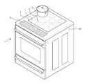
도 1은 본 발명의 일 실시예에 따른 유도가열조리기의 구성을 도시한 사시도이다.1 is a perspective view showing the configuration of an induction heating cooker according to an embodiment of the present invention.
본 발명인 유도가열조리기는 케이스(1)를 구비한다. 케이스(1) 상측에는 용기(3)을 올려 놓을 수 있도록 마련된 조리판(2)가 설치된다. 케이스(1) 내부에는 조리판(2) 하부에 설치되어 조리판(2)에 열원을 제공하기 위한 하나 이상의 가열코일(L)이 설치된다. 한 열로 이루어진(도 1에서는 4개의 가열코일(L)이 한 개의 가열코일 군(L1~L4)을 형성한다.) 네 개의 가열코일 군(L1~L4)은 제어부(60)에 의해 동작하는 구동부(도 2의 40)에 의해 동작한다. 또한 하나 이상의 가열코일(L) 각각이 제어부(60)에 의해 동작하는 구동부(40)에 의해 동작할 수 있다. 조리판(2)의 하부에 있는 가열코일(L)은 N*N 행렬 형태로 배치될 수 있다. 본 발명의 일 실시예에 의하면 4*4 행렬 형태로 가열코일(L)이 배치되어있다.Induction heating cooker of the present invention is provided with a case (1). The cooking plate 2 provided to put the
또한, 조리판(2)의 하부에는 가열코일(L) 또는 조리판(2)의 온도를 감지하는 온도감지기(4)가 위치한다. 온도감지기(4)는 가열코일(L) 또는 조리판(2)의 온도를 감지하여 제어부(60)로 신호를 전송한다. 이 신호에 기초하여 제어부(60)는 감지된 온도를 디스플레이부(70) 또는 다른 표시부에 표시하도록 제어한다.In addition, a temperature sensor 4 for detecting a temperature of the heating coil L or the cooking plate 2 is located below the cooking plate 2. The temperature sensor 4 detects the temperature of the heating coil L or the cooking plate 2 and transmits a signal to the
케이스(1)의 다른 상측에는 조작패널(6)이 위치한다. 조작패널(6)은 디스플레이부(70), 조작부(80) 및 플레이트(5)로 구성된다.The
도 2는 본 발명의 일 실시예에 따른 유도가열조리기의 조리판 하부의 내부구조를 도시한 평면도이다.2 is a plan view showing the internal structure of the cooking plate lower portion of the induction heating cooker according to an embodiment of the present invention.
발명의 일 실시예에 따른 유도가열조리기는 정류부(10)와, 평활부(20)와, 인버터부(30~32)와, 구동부(40~42)와, 감지부(50~52), 제어부(60), 디스플레이부(70) 및 조작부(80)를 포함한다. Induction heating cooker according to an embodiment of the present invention, the
각 가열코일 군(L1~L4)은 각 인버터(30~32)에 의해 독립적으로 구동된다. 또한, 개개의 가열코일(L)이 복수 개의 인버터(30~32)에 의해 독립적으로 구성될 수 있다. 제1 가열코일 군(L1~L4)은 제1 인버터(30)에 의해 구동되고, 제2 가열코일 군(L1~L4)은 제2 인버터(31)에 의해 구동되며, 제3 가열코일 군(L1~L4)은 제3 인버터(32)에 의해 구동된다. 가열코일 군(L1~L4)과 인버터는 상호 대응하도록 복수 개가 구비될 수 있다. 또한, 개개의 가열코일(L)과 인버터는 상호 대응하도록 복수 개가 구비될 수 있다. 도 2에서는 네 개의 가열코일(L)로 이루어진 가열코일 군(L1~L4)이 네 개이고, 이 가열코일 군(L1~L4)을 구동하는 인버터가 네 개(30~32)로 구성된 것을 도시하고 있다.Each heating coil group L1 to L4 is independently driven by each
인버터부(30~32)는 메인 스위칭소자(Q1, Q2)와, 보조 스위칭소자(S1~S4), 콘덴서(C1, C2)를 포함한다. 메인스위칭소자(Q1, Q2)는 평활부(20)로부터 출력된 평활전압을 구동부(40~42)의 스위칭제어신호에 따라 교대로 스위칭하여 각 가열코일(L1~L4)에 고주파전원을 공급한다. 제1 콘덴서(C1)와 제2 콘덴서(C2)는 각 가열코일(L1~L4)에 전류가 흐르도록 하는 역할을 한다.The
감지부(50~52)에서 감지한 전류에 기초해서 용기(3)가 위치하는 가열코일(L)에 상응하는 영역 및 출력조절부(200)를 조작패널(6)에 표시하고 표시된 영역(100) 및 출력조절부(200)가 사용자에 의해 조작패널(6)를 통해 선택되면, 제어부(60)가 용기가 위치하는 가열코일(L)의 출력을 조절하는 제어신호를 구동부(40)에 보내고 구동부(40)가 이에 의해 각 가열코일(L)을 구동시킨다.The region corresponding to the heating coil L on which the
또한, 감지부(50, 51, 52)는 전류를 감지하는 전류센서 뿐만 아니라 전압센서, 압력센서, 적외선 센서 등 다양한 형태로 가열코일 상에 위치하는 용기(3)를 감지할 수 있다.In addition, the
제어부(60)는 조작패널(6)을 통해 신호가 입력되면, 각 가열코일 군(L1~L4)을 대상으로 각 가열코일(L1~L4)에 용기(3)이 있는지 없는지를 각각 감지하기 위해 각 가열코일 군(L1~L4)별로 각 가열코일(L1~L4)에 전류가 순차적으로 흐르도록 구동부(30)를 통해 인버터부(30)의 작동을 제어한다.When a signal is input through the
또한, 제어부(60)는 감지부(50~52)를 통해 감지된 전류값에 따라 각 가열코일 군(L1~L4)별로 각 가열코일(L1~L4)에 용기(3)이 있는지 없는지를 판단한다.In addition, the
또한, 제어부(60)는 용기(3)이 놓여 있는 것으로 판단된 가열코일들에 대해서는 각 가열코일 군(L1~L4)별로 가열코일 상에 위치하는 용기(3)의 정보를 조작패널(6)에 표시시킨다. 이에 따라, 사용자는 조작패널(6) 상에 표시되는 출력조절부(200)를 통해 용기(3)가 놓인 가열코일의 출력을 입력하게 된다. 제어부(60)는 용기(3)가 놓인 가열코일에 순차적으로 고주파전원을 공급하여 해당 가열코일에 놓인 용기(3)를 가열시킨다.In addition, the
도 3a는 본 발명의 일 실시예에 따른 유도가열조리기의 조작패널을 도시한 분해 사시도이다.Figure 3a is an exploded perspective view showing the operation panel of the induction heating cooker according to an embodiment of the present invention.
먼저 조작패널(6)의 상부에 플레이트(5)가 위치하고 그 아래에 조작부(80)가 위치한다. 조작부(80)의 아래에 디스플레이부(70)가 위치한다. 조작부(80)와 디스플레이부(70)에는 전원을 공급하는 고주파전원부(90)가 연결된다. 또한 조작부(80)와 디스플레이부(70)를 제어하는 제어부(60)가 조작부(80)와 디스플레이부(70)에 각각 연결된다.First, the plate 5 is positioned above the
디스플레이부(70)는 LCD, PDP, EL, CRT 또는 LED 등 다양한 형태로 될 수 있다. 디스플레이부(70)는 가열코일에 위치하는 용기(3)에 대응하는 일정 영역 또는 해당 가열코일(L)의 출력조절부(200, 500)를 표시한다.The
조작부(80)는 터치패널 등 사용자에 의한 입력신호를 받아들이는 다양한 형태로 될 수 있다. 터치를 감지하는 방법에 따라 저항형(resistive type), 정전 용량형(capacitive type), 적외선 센서형 또는 광 센서형 등으로 구분할 수 있다.The
조작부(80)는 사용자에 의해 선택되는 용기(3)나 사용자에 의해 조절되는 출력조절부(도 4의 200)의 신호를 제어부(60)로 보내고 제어부(60)는 이 신호에 기초하여 가열코일(L)의 출력을 제어한다. 플레이트(5)는 투명 재질로 구성될 수 있다.The
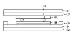
도 3b는 본 발명의 일 실시예에 따른 터치 패널 조작부의 구성을 도시한 종단면도이다.3B is a longitudinal cross-sectional view illustrating a configuration of a touch panel operation unit according to an embodiment of the present invention.
터치 패널 조작부(80)는 상부 전극(83)이 형성된 상부 투명기판(81)과, 하부 전극(84)이 형성된 하부 투명 기판(82)이 일정 공간을 갖고 적층되어 있는 구조로 되어 있다. 상부 전극(81)이 형성되어 있는 상부 기판(81)에 펜 또는 손가락 등의 입력 수단으로 어느 한 지점에 접촉하게 되면, 상부 기판(81)에 형성된 상부 전극(83)과 하부 기판(82)에 형성된 하부 전극(84)이 상호 통전되고, 그 위치의 저항값 또는 커패시터 값에 의하여 변화된 전압값을 읽어들인 후 제어부(60)에서 전위차의 변화에 따라 위치 좌표를 찾게 되는 장치이다.The touch
터치 패널 조작부(80)는 디스플레이부(70)의 표시면 위에 설치되어 신호 입력 수단으로 이용되는 것이므로, 디스플레이부(70)의 표시면에 해당되는 표시 영역과, 표시 영역을 감싸도록 표시 영역 주변부에 형성되는 데드 스페이스 영역으로 구분된다. 데드 스페이스에서 상하 기판(81, 82)이 절연성 접착제에 의해 합착되고, 디스플레이부(70)의 아래 면에 상응하는 PET(Poly Ethylene Terephtalate) 기판(81, 82)의 내측면에 투명 전극(83, 84)이 형성되고, 기판은 간격을 갖고 절연성 접착제에 의해 데드 스페이스 영역에서 합착된다. 상하부기판(81, 82)에 제1, 2 금속전극(85, 86)이 형성된다. 펜이나 손가락 등으로 상부 기판(81)에 접촉하게 되면 투명 전극(83, 84)이 점에서 상호 접촉되어 그 위치의 저항치에 의하여 변화된 값이 출력되게 된다. 상부기판(81)에 형성된 제1 금속전극(85)과 하부기판(82)에 형성된 콘택배선(88)은 도전 접착제(89)를 통해 접촉된다.Since the touch
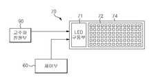
도 3c는 본 발명의 일실시예에 따른 LED로 이루어진 디스플레이부의 구성을 도시한 블록도이다.Figure 3c is a block diagram showing the configuration of a display unit consisting of LEDs according to an embodiment of the present invention.
본 발명의 일 실시예에 따른 LED를 이용한 표시부에 대하여 상술하지만, 본 발명은 이에 한정되지 아니하고 LCD, PDP, CRT 등 다른 디스플레이 장치도 포함된다. LED로 구성된 디스플레이부(70)는 고주파전원부(90), 제어부(60), LED 유닛(74)을 포함한다. LED 유닛(74)은 LED 구동부(71)와 복수의 LED 어레이들(72)을 포함한다. 제어부(60)는 LED 유닛(74) 내의 복수의 LED 어레이들(72)의 각각에 관한 제어 신호를 제공한다. 제어 신호는 LED 유닛(14) 내의 LED 어레이들(72)에 관하여 전체적인 색 온도와 밝기를 유지할 수 있도록 생성되는 디지털 신호 또는 아날로그 신호일 수 있다.Although the display unit using the LED according to an embodiment of the present invention is described above, the present invention is not limited thereto, and other display devices such as LCD, PDP, and CRT are also included. The
복수의 LED 어레이들(72)은 인쇄 회로 기판(PCB, printed circuit board)의 일정구획 위에 일정한 수의 행과 열을 가지고 배열된 다수의 LED들을 포함한다(LED Matrix). LED 구동부(71)는 정전압 구동 방식 또는 정전류 구동 방식으로 각각의 LED 어레이(72) 내의 LED들을 구동할 수 있다.The plurality of
도 4는 본 발명의 일 실시예에 따른 디스플레이부가 가열코일 위에 위치하는 용기에 대응하는 영역을 도시한 평면도이다.4 is a plan view illustrating a region corresponding to a container positioned on a heating coil according to an embodiment of the present invention.
사용자에 의해 조리판(2) 위에 올려진 용기(3)가 4개(100, 101, 102, 103)인 경우에, 가열코일 위에 위치하는 용기(3)에 상응하는 일정 영역을 디스플레이부(70)가 나타내고 있다. 사용자에 의해 영역(101)이 선택되면 도 5 내지 도 7의 디스플레이부(70) 화면으로 전환하게 된다.In the case where four
디스플레이부(70)는 용기(3)가 올려지는 조리판(2)의 너비와 폭이 가지는 비율로 구성될 수 있다. 조리판(2)이 디스플레이부(70) 보다 큰 경우에 조리판(2)의 너비와 폭의 비율로 축소된 형태로 디스플레이부(70)가 구성될 수 있다.The
또한, 디스플레이부(70)는 감지된 용기(3)의 조리판(2) 상의 실제 위치에 대응하는 디스플레이부(70)의 위치에 감지된 용기(3)를 표시할 수 있다. 즉 조리판(2) 상에 위치하는 용기(3)를 일정 비율로 모방(mimic)하여 디스플레이부(70)에 표시할 수 있는 것이다.In addition, the
도 5는 본 발명의 일 실시예에 따른 용기가 위치하는 가열코일의 출력을 조절하기 위해 조작패널에 나타난 영역을 터치한 경우 유도가열조리기의 조작패널을 도시한 평면도이다.FIG. 5 is a plan view illustrating an operation panel of an induction heating cooker when an area shown in the operation panel is touched to adjust an output of a heating coil in which a container is positioned, according to an embodiment of the present invention.
사용자의 선택에 의해서 전환된 조작패널(6)은 가열코일(L)에 위치하는 용기(3)에 상응하는 영역(111)과 출력조절부(200, 500)를 표시한다. 표시된 영역(111)과 출력조절부(200)는 조작패널(6)의 일 부분에 표시될 수 있다. 표시된 영역(111)은 사용자에 의해 선택되기 전 영역(101)의 형태를 유지하거나 축소 또는 확대되어서 표시될 수 있다.The
출력조절부(200)는 +,-형태로 구성될 수 있으며, 사용자가 해당 가열코일의 출력을 조절할 수 있게 하는 부분이다. 또한 출력조절부(200)는 ↑, ↓형태 등 다양하게 표시될 수 있다.The
출력조절부(500)는 막대 슬라이드 형태는 구성되며, 슬라이드 막대는 현재 가열코일에 가해지는 출력을 표시하고 막대 슬라이드의 길이가 길면 해당 가열코일의 출력이 높은 것을 나타낸다. 또한 슬라이드 막대는 그 모양이나 색깔, 배치 순서 등 그 요소가 다양한 형태로 표시될 수 있다.The
또한, 조작패널(6)은 +,-형태의 출력조절부(200)와 막대 슬라이드 형태의 출력조절부(500)를 각각 표시하거나 둘 이상을 표시할 수 있다.In addition, the
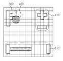
도 6은 본 발명의 다른 실시예에 따른 용기가 위치하는 가열코일의 출력을 조절하기 위해 조작패널에 나타난 영역을 터치한 경우 유도가열조리기의 조작패널을 도시한 평면도이다.FIG. 6 is a plan view illustrating an operation panel of an induction heating cooker when an area shown on the operation panel is touched to adjust the output of a heating coil in which a container is positioned according to another embodiment of the present invention.
도 4 상에서 조작패널(6)에 표시된 영역 중에서 하나를 손으로 선택하면 +, - 형태의 출력조절부(210)와 슬라이드 형태의 출력조절부(510)가 표시된다. 두 출력조절부(210, 510)는 도 5에서 살펴본 것과 같이 다양한 형태로 표시될 수 있다. 또한 조작 대상이 되는 해당 용기(3)의 정보에 상응하는 표시(400)가 나타내진다. 표시(400)는 다른 색 또는 점멸하고 있는 형태 등 다양한 방식으로 구분되어 나타내질 수 있다.4, if one of the areas displayed on the
또한, 현재 해당 가열코일의 출력을 나타내는 표시(300)가 표시된다. 도 6에 나타난 것과 같이 문자(P는 Boost, H는 high, L은 low, S는 Simmer)로 표시될 수도 있고, 숫자 등 다양한 형태로 표시될 수 있다. 슬라이드 조절부(510)의 슬라이드의 길이가 길수록 가열코일에 대한 출력은 높은 것이고, 사용자에 의해 슬라이드가 조절되는 것으로 해당 가열코일들의 출력이 조절될 수 있다.In addition, a
도 7은 본 발명의 또 다른 실시예에 따른 용기가 위치하는 가열코일의 출력을 조절하기 위해 조작패널에 나타난 영역을 터치한 경우 유도가열조리기의 조작패널을 도시한 평면도이다.FIG. 7 is a plan view illustrating an operation panel of an induction heating cooker when an area shown in the operation panel is touched to adjust an output of a heating coil in which a container is located, according to another embodiment of the present invention.
도 4 상에서 조작패널(6)에 표시된 영역 중에서 하나를 손으로 선택하면 +, - 형태의 출력조절부(220)와 슬라이드 형태의 출력조절부(520)가 표시된다. 두 출력조절부(220, 520)는 도 5에서 살펴본 것과 같이 다양한 형태로 표시될 수 있다.4, if one of the areas displayed on the
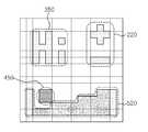
또한, 조작되는 가열코일의 위치 정보에 상응하는 표시(450)가 표시된다. 표시(450)는 다른 색 또는 점멸하고 있는 형태 등 다양한 방식으로 표시될 수 있다. 또한 현재 해당 가열코일의 출력을 나타내는 표시(350)가 표시된다. 도 7에 나타난 것과 같이 문자로 표시될 수도 있고, 숫자 등 다양한 형태로 표시될 수 있다. 슬라이드 조절부(520)의 슬라이드의 높이가 높을 수록 가열코일에 대한 출력은 높은 것이고, 사용자에 의해 슬라이드가 선택되는 것으로 해당 가열코일들의 출력이 조절될 수 있다.In addition, a
도 5 내지 도 7에 도시된 디스플레이부(70) 상의 출력조절부(200, 210, 220)는 별도의 디스플레이부에 표시되어 조절될 수 있고 키, 버튼, 다이얼 또는 스위치 등으로 구성된 별도의 조작부에 포함되어 출력조절의 수단이 될 수 있다.
또한, 가열시간을 조절할 수 있는 타이머가 추가적으로 구비될 수 있으며, 출력조절부(200, 210, 220)와 같이 디스플레이부(70) 또는 별도의 디스플레이부에 표시되어 조절될 수 있고 키, 버튼, 다이얼, 스위치 등으로 구성된 별도의 조작부에 포함되어 조작될 수 있다.In addition, a timer for adjusting the heating time may be additionally provided, and may be displayed and adjusted on the
또한, 도 5 내지 도 7에는 도시되지 않았으나 본 발명의 일 실시예에 의하면 온도감지부(4)에 의해 측정된 온도나 감지된 용기(3)에 대한 가열시간을 디스플레이부(70) 또는 그 외부에 숫자, 문자, 슬라이드 등의 형태로 표시될 수 있다.In addition, although not shown in FIGS. 5 to 7, according to an embodiment of the present invention, the temperature measured by the temperature sensing unit 4 or the heating time for the detected
도 8은 본 발명의 일 실시예에 따른 감지된 용기가 실제로 표시되는 유도가열조리기의 디스플레이부를 도시한 평면도이다.8 is a plan view illustrating a display unit of an induction heating cooker in which a sensed container is actually displayed according to an embodiment of the present invention.
도 4와 같이 표시된 디스플레이부(70)가 실제로 사용자에게 보여지는 디스플레이부(70) 화면을 나타낸다. 디스플레이부(70)의 LED는 복수 개의 색을 나타낼 수 있도록 구성될 수 있다. 도 8은 두 개의 용기(3)가 조리판(2)에 올려진 경우에 조작패널(6)이 각 용기가 올려진 해당 가열코일을 다른 색으로 구분하여 표시한 것이다.The
도 9는 본 발명의 또 다른 실시예에 따른 인식된 용기의 상태와 출력조절부가 실제 표시되는 유도가열조리기의 조작패널을 도시한 평면도이다.9 is a plan view illustrating an operation panel of an induction heating cooker in which a state of a recognized container and an output control unit are actually displayed according to another embodiment of the present invention.
도 7에 대해 사용자가 실제로 보게 되는 조작패널(6)의 구성을 나타낸다. 출력조절부(220, 520)와 출력디스플레이부(350)와 위치디스플레이부(450)는 서로 다른 색 또는 모양의 LED로 구분되어 표시될 수 있다.7 shows the configuration of the
도 10은 본 발명의 일 실시예에 따른 용기가 제거된 후 유도가열조리기의 잔열을 표시하는 조작패널에 도시한 평면도이다.10 is a plan view showing an operation panel displaying the residual heat of the induction heating cooker after the container is removed according to an embodiment of the present invention.
하나 이상의 온도감지부(4)는 조리판(2)의 하부에 위치한다. 용기(3)가 제거되기 전 또는 제거된 후의 조리판(2) 또는 각 가열코일(L)의 온도를 감지한다. 또한 조리판(2)과 각 가열코일(L) 사이의 온도를 감지하는 형태로 실시될 수 있다.At least one temperature sensing unit 4 is located below the cooking plate 2. The temperature of the cooking plate 2 or each heating coil L is sensed before or after the
감지된 온도는 제어부(60)로 전송되고, 제어부(60)는 디스플레이부(70)에 감지된 온도를 다른 색의 LED로 나타내거나 도 10에서 나타낸 격자 모양 등 다양한 형태로 구분하여 표시하도록 제어한다. 이로 인해서 용기를 가열 후 가열조리기에 잔열이 남아있는 경우를 사용자가 인지할 수 있고 화상 등의 위험을 미리 방지할 수 있다. 또한 온도는 상기 디스플레이부(70) 외부에 따로 표시되어 실시될 수 있다.The sensed temperature is transmitted to the
또한, 감지된 온도값을 입력받은 제어부(60)는 입력된 온도값이 일정 기준값보다 크면 가열코일(L)의 출력을 감소시키는 제어를 수행할 수 있다. 이로 인해서 용기(3)가 과도하게 가열되면 자동으로 가열코일의 출력을 줄여서 가열코일 자체의 동작상 문제가 생길 만큼의 온도로 올라가는 것을 방지할 수 있다.In addition, the
도 11은 본 발명의 일 실시예에 따른 가열코일 상에 용기가 위치하는지 여부를 제어부가 인식하지 못한 경우에 수동으로 인식 영역을 설정하는 평면도이다.11 is a plan view of manually setting a recognition area when the controller does not recognize whether a container is positioned on a heating coil according to an embodiment of the present invention.
두 개 이상의 용기(3)이 근접하여 조리판(2) 위에 배치되더라도, Power on상태에서 시차를 두고 올려질 경우 감지부(50)는 용기(3)을 두 개로 판단한다. 다만, Power on 전에 이미 두 개 이상의 용기(3)가 근접한 위치에 올려져 있거나, 동시에 조리판(2)에 용기(3)가 위치하여서 제어부(60)에서 용기(3)의 개수나 크기 등의 정보를 확인하기 어려울 경우 또는 오작동하는 경우에 조작패널(6) 상에서 사용자의 드래그(drag)를 통해 수동으로 용기 감지 영역이 설정되고 이에 따라 제어부(60)가 가열코일 (L) 상에 위치하는 용기(3)의 유무를 판단할 수 있도록 한다.Even if two or
또한 도 11과는 달리, 용기(3)가 제대로 인식되지 않은 경우에 사용자에 의해 용기(3)가 다시 올려질 수 있도록 사용자에게 경고할 수 있다. 이미 두 개가 올려져 있거나 동시에 올려지는 경우, 제어부(60)는 디스플레이부(70)가 경고하는 색 또는 문자 또는 깜빡거림 등을 나타내도록 제어할 수 있다. 또한, 경고음을 낼 수 있는 장치를 추가적으로 설치하여 사용자에게 용기(3)가 잘못 올려졌음을 알릴 수 있다.In addition, unlike FIG. 11, it is possible to warn the user so that the
도 12는 본 발명의 일 실시예에 따른 유도가열조리기의 동작과정을 도시한 순서도이다. 도 12를 통해서 본 발명의 일 실시예에 따른 유도가열조리기의 동작과정을 설명한다.12 is a flowchart illustrating the operation of the induction heating cooker according to an embodiment of the present invention. Referring to Figure 12 describes the operation of the induction heating cooker according to an embodiment of the present invention.
사용자에 의해 조리판(2)에 올려진 용기(3)를 감지하는 감지부(50)의 신호를 기초로 제어부(60)가 용기(3)의 유무를 판단한다. 일 예로, 용기(3)가 위치한 가열코일(L)의 전류나 전압 등의 전기적 신호의 변화를 감지하는 감지부(50)의 신호를 기초로 제어부(60)는 용기(3)의 유무를 판단할 수 있다. 감지된 신호가 없으면 제어부(60)는 다시 감지부(50)가 전기적 신호의 변화를 감지하도록 제어하고(701), 감지된 신호가 있으면 디스플레이부(70)는 감지된 용기(3)에 상응하는 일정 영역을 디스플레이한다(702).The
제어부(60)는 감지된 용기(3)에 상응하는 일정 영역이 사용자에 의해 선택되는지 판단한다. 선택이 되지 않은 경우에는 제어부(60)가 용기(3)의 유무를 판단하는 과정을 반복하고, 선택이 된 경우에는 조작패널(6)이 일정 영역과 상응하는 가열코일(L)의 출력을 조절할 수 있는 출력조절부(200, 210, 220)를 표시한다(703, 704). 표시된 출력조절부(200, 210, 220)가 사용자에 의해 조절되지 않은 경우에는 제어부(60)가 가열코일 상에 용기(3)가 위치하는지 판단하는 과정을 반복하고, 출력조절부(200, 210, 220)가 사용자에 의해 조절이 되면 제어부(60)가 그에 따라 해당 가열코일(L)의 출력을 제어한다(705, 706).The
또한, 제어부(60)는 복수 개의 용기(3) 중에 선택된 용기(3)에 대한 가열코일의 출력조절이 끝나면, 사용자에 의해 선택된 다른 용기(3)의 출력을 조절하기 위해서, 일정 시간 경과 시 복수 개의 용기(3)가 표시된 처음 화면으로 돌아가게 제어하거나 또는 조작 패널(6)의 일정 영역을 사용자가 선택하는 것으로 복수 개의 용기(3)가 표시된 처음 화면으로 돌아가게 제어할 수 있다. 여기서 일정 영역은 감지된 용기(3)에 상응하는 영역 또는 또 다른 조작부가 될 수 있다. 또한, 처음 화면으로 돌아가는 조작부가 디스플레이부(70) 상이 아닌 따로 설치된 다이얼, 버튼, 스위치나 다른 디스플레이부의 구성으로 이루어질 수 있다.In addition, when the control of the output of the heating coil for the
또한, 조작패널(6)에 타이머가 추가적으로 위치하거나 또 다른 디스플레이부에 위치할 수 있고, 이를 통해 사용자가 원하는 시간 동안 해당 용기(3)를 가열할 수 있다. 또, 타이머는 조작패널(6) 외부에 따로 마련된 조작부에 키, 다이얼, 스위치 등의 형태로 설치될 수 있다.In addition, a timer may be additionally located on the
도 12에서 설명한 유도가열조리기의 동작과정은 복수 개의 가열코일(L)이 있는 조리판(2)에 하나 이상의 용기(3)가 위치하는 경우이다. 이와 달리 한 개의 가열코일(L)이 있는 조리판(2)에 하나의 용기(3)가 위치하는 경우에는 도 12의 과정(703)이 제외되고 유도가열조리기가 동작할 수 있다. 즉, 사용자의 선택여부와 관계없이 도 5에서와 같이 바로 조작패널(6)이 감지된 용기(3)에 상응하는 영역과 출력조절부(200, 210, 220)를 표시할 수 있다.The operation process of the induction heating cooker described in FIG. 12 is a case where one or
2 : 조리판4 : 온도감지부6 : 조작패널
200, 210, 220 : 출력조절부
300, 350 : 가열코일의 출력 디스플레이부
400, 450 : 용기의 위치 디스플레이부
500, 510, 520 : 출력조절부
600 : 잔열디스플레이부2: cooking plate 4: temperature sensing unit 6: operation panel
200, 210, 220: Output control part
300, 350: output display unit of the heating coil
400, 450: position display of the container
500, 510, 520: Output control part
600: residual heat display unit
Claims (24)
Translated fromKorean상기 가열코일 위에 위치하는 용기를 감지하는 감지부;
상기 감지된 용기를 표시하는 디스플레이부를 포함하는 유도가열조리기.A heating coil for heating the container;
A sensing unit for sensing a container positioned on the heating coil;
Induction heating cooker comprising a display unit for displaying the sensed container.
상기 가열코일의 출력을 조절하는 출력조절부를 더 포함하는 유도가열조리기.The method of claim 1,
Induction heating cooker further comprises an output control unit for adjusting the output of the heating coil.
상기 디스플레이부는 조작패널 기능을 가지는 유도가열조리기.The method of claim 2,
The display unit is an induction heating cooker having a control panel function.
상기 디스플레이부는 상기 출력조절부를 표시하는 유도가열조리기.The method of claim 3,
The display unit is an induction heating cooker to display the output control unit.
상기 출력조절부는 상기 디스플레이부와는 별도로 표시되는 제2 디스플레이부인 것을 특징으로 하는 유도가열조리기.The method of claim 2,
The output control unit is an induction heating cooker, characterized in that the second display unit is displayed separately from the display unit.
상기 출력조절부가 다이얼, 버튼 또는 슬라이드 형태로 구성되는 유도가열조리기.The method of claim 2,
Induction heating cooker wherein the output control unit is configured in the form of a dial, a button or a slide.
상기 디스플레이부는 상기 용기가 올려지는 조리판의 가로, 세로와 대응하며 소정 비율로 축소되어 나타내지는 유도가열조리기.The method of claim 1,
The display unit corresponds to the horizontal and vertical of the cooking plate on which the container is mounted, the induction heating cooker is reduced to a predetermined ratio.
상기 디스플레이부는 상기 감지된 용기의 조리판 상의 실제 위치에 대응하는 디스플레이부의 위치에 상기 감지된 용기를 표시하는 유도가열조리기.The method of claim 7, wherein
And the display unit displays the detected container at a position of the display unit corresponding to an actual position on the cooking plate of the detected container.
상기 디스플레이부는 상기 용기 하부에 위치하는 가열코일의 출력을 표시하는 유도가열조리기.The method of claim 8,
The display unit is an induction heating cooker to display the output of the heating coil located under the container.
상기 감지부가 하나 이상의 용기를 감지하는 유도가열조리기.10. The method of claim 9,
Induction heating cooker for detecting the sensing unit one or more containers.
상기 디스플레이부는 상기 하나 이상인 용기들 중에서 사용자에 의해 선택된 용기의 영역을 표시하는 유도가열조리기.The method of claim 10,
And the display unit displays an area of a container selected by a user among the one or more containers.
상기 디스플레이부는 상기 용기에 대응하는 영역이 일정 시간 동안 선택되지 않는 경우에 하나 이상의 용기가 디스플레이된 화면으로 복귀하는 유도가열조리기.The method of claim 10,
And the display unit returns to a screen on which one or more containers are displayed when an area corresponding to the container is not selected for a predetermined time.
상기 조리판 또는 가열코일의 온도를 감지하는 온도감지부를 더 포함하는 유도가열조리기.The method of claim 7, wherein
Induction heating cooker further comprises a temperature sensing unit for sensing the temperature of the cooking plate or heating coil.
상기 디스플레이부는 상기 온도감지부에 의해 감지된 온도를 표시하는 유도가열조리기.The method of claim 13,
The display unit is an induction heating cooker to display the temperature sensed by the temperature sensor.
상기 디스플레이부는 LED 또는 LCD로 구성되는 유도가열조리기.The method of claim 14,
The display unit is an induction heating cooker consisting of LED or LCD.
상기 조작패널은 터치패널 기능을 가지는 유도가열조리기.16. The method of claim 15,
The operation panel is an induction heating cooker having a touch panel function.
상기 디스플레이부는 하나 이상의 색을 나타내는 LED 또는 LCD를 포함하고, 상기 가열코일들의 온도 표시를 상기 온도에 따라 다른 색 또는 모양의 LED 또는 LCD로 표시하는 가열조리기.The method of claim 16,
The display unit includes a LED or LCD showing one or more colors, the heating cooker to display the temperature display of the heating coils with LEDs or LCDs of different colors or shapes according to the temperature.
상기 디스플레이부는 상기 선택된 영역을 점멸하며 표시하는 유도가열조리기.The method of claim 11,
And the display unit flashes and displays the selected area.
상기 디스플레이부는 상기 점멸하며 표시되는 영역이 다시 선택된 경우 상기 선택된 영역을 표시하는 유도가열조리기.The method of claim 18,
And the display unit displays the selected area when the blinking and displayed area are selected again.
상기 감지부는 상기 용기가 위치하는 가열코일 감지를 통해 상기 용기를 감지하는 유도가열조리기.The method of claim 1,
The sensing unit is an induction heating cooker for sensing the container by detecting the heating coil in which the container is located.
상기 감지부는 상기 가열코일로 흐르는 전류 또는 전압을 감지하여 상기 용기를 감지하는 유도가열조리기.The method of claim 20,
The sensing unit senses the vessel by sensing the current or voltage flowing to the heating coil induction heating cooker.
상기 감지된 용기를 디스플레이부에 표시하는 유도가열조리기 제어방법.Sensing a vessel located on the heating coil;
Induction heating cooker control method for displaying the detected container on the display.
상기 가열코일의 출력을 조절하는 출력조절부를 상기 디스플레이부에 표시하고 출력조절부를 조작하는 것을 더 포함하는 유도가열조리기 제어방법.The method of claim 22,
And displaying an output control unit for controlling the output of the heating coil on the display unit and manipulating an output control unit.
상기 감지된 용기들을 디스플레이부에 표시하고;
상기 디스플레이부에 표시된 용기들 중 사용자에 의해 선택된 용기에 대한 출력을 조절하는 유도가열조리기 제어방법.Detecting one or more containers positioned on the heating coil;
Displaying the detected containers on a display unit;
An induction heating cooker control method for adjusting the output for the container selected by the user of the containers displayed on the display.
Priority Applications (4)
| Application Number | Priority Date | Filing Date | Title |
|---|---|---|---|
| KR1020100056090AKR20110136226A (en) | 2010-06-14 | 2010-06-14 | Induction heating cooker and control method |
| EP11163830.0AEP2395813B1 (en) | 2010-06-14 | 2011-04-27 | Induction heating cooker and control method thereof |
| CN201110129550.XACN102297461B (en) | 2010-06-14 | 2011-05-12 | Induction heating cooker and control method thereof |
| US13/158,869US20110303653A1 (en) | 2010-06-14 | 2011-06-13 | Induction heating cooker and control method thereof |
Applications Claiming Priority (1)
| Application Number | Priority Date | Filing Date | Title |
|---|---|---|---|
| KR1020100056090AKR20110136226A (en) | 2010-06-14 | 2010-06-14 | Induction heating cooker and control method |
Publications (1)
| Publication Number | Publication Date |
|---|---|
| KR20110136226Atrue KR20110136226A (en) | 2011-12-21 |
Family
ID=44121444
Family Applications (1)
| Application Number | Title | Priority Date | Filing Date |
|---|---|---|---|
| KR1020100056090ACeasedKR20110136226A (en) | 2010-06-14 | 2010-06-14 | Induction heating cooker and control method |
Country Status (4)
| Country | Link |
|---|---|
| US (1) | US20110303653A1 (en) |
| EP (1) | EP2395813B1 (en) |
| KR (1) | KR20110136226A (en) |
| CN (1) | CN102297461B (en) |
Cited By (11)
| Publication number | Priority date | Publication date | Assignee | Title |
|---|---|---|---|---|
| KR20150095141A (en)* | 2014-02-12 | 2015-08-20 | 삼성전자주식회사 | Method and device for cooking |
| KR101860490B1 (en)* | 2018-01-12 | 2018-05-23 | 주식회사 아미크론 | Induction range to detect position of container |
| KR20190038170A (en)* | 2017-09-29 | 2019-04-08 | 엘지전자 주식회사 | Induction heating and wireless power transferring device having improved target detection algorithm |
| KR20190043984A (en)* | 2017-10-19 | 2019-04-29 | 엘지전자 주식회사 | Induction heating and wireless power transferring device having improved resonant current detection accuracy |
| KR20190043985A (en)* | 2017-10-19 | 2019-04-29 | 엘지전자 주식회사 | Induction heating device having improved target detection accuracy and, induction heating system comprising the same |
| KR20200122714A (en)* | 2019-04-18 | 2020-10-28 | 엘지전자 주식회사 | Induction heating device having improved user experience and user interface |
| KR20200122713A (en)* | 2019-04-18 | 2020-10-28 | 엘지전자 주식회사 | Induction heating device having improved user experience and user interface |
| KR20200137783A (en)* | 2019-05-31 | 2020-12-09 | 코웨이 주식회사 | Control method of automatic cooking using electric range having faucet |
| KR102252570B1 (en)* | 2019-11-27 | 2021-05-17 | (주)신화셀렉스 | Electric range capable of recognizing shape and size of cooking vessel using capacitance sensors |
| KR20230001130U (en)* | 2021-11-25 | 2023-06-02 | 주식회사 셰프라인 | Induction range |
| KR20230079337A (en)* | 2016-11-02 | 2023-06-07 | 에스케이매직 주식회사 | Induction range |
Families Citing this family (35)
| Publication number | Priority date | Publication date | Assignee | Title |
|---|---|---|---|---|
| KR101835714B1 (en) | 2011-04-01 | 2018-03-08 | 삼성전자주식회사 | Induction heating cooker and control method thereof |
| DE102011087479A1 (en)* | 2011-11-30 | 2013-06-06 | BSH Bosch und Siemens Hausgeräte GmbH | Method for operating a hob and hob |
| ES2439418B1 (en)* | 2012-07-20 | 2015-03-12 | Bsh Electrodomesticos Espana | Cooking Field Device |
| ES2439417B1 (en) | 2012-07-20 | 2015-03-12 | Bsh Electrodomesticos Espana | Cooking Field Device |
| EP2704523B2 (en) | 2012-09-03 | 2019-12-18 | BSH Hausgeräte GmbH | Induction cooking hob device |
| EP2708818B1 (en)* | 2012-09-13 | 2021-04-14 | BSH Hausgeräte GmbH | Cooking hob device |
| US10605464B2 (en) | 2012-10-15 | 2020-03-31 | Whirlpool Corporation | Induction cooktop |
| ITTO20120896A1 (en) | 2012-10-15 | 2014-04-16 | Indesit Co Spa | INDUCTION HOB |
| CN104221470B (en)* | 2012-10-22 | 2016-08-24 | 松下电器产业株式会社 | induction heating cooker |
| CN104033933A (en)* | 2013-03-06 | 2014-09-10 | 美的集团股份有限公司 | Electromagnetic induction heater and control method thereof |
| DE102013206758A1 (en) | 2013-04-16 | 2014-10-16 | BSH Bosch und Siemens Hausgeräte GmbH | Hob with a cooking zone and a reduced symbol representation in the cooking zone in a display unit and method for operating a hob |
| US10098188B2 (en) | 2013-04-25 | 2018-10-09 | Panasonic Intellectual Property Management Co., Ltd. | Induction heating cooker |
| JP6268613B2 (en)* | 2013-06-11 | 2018-01-31 | パナソニックIpマネジメント株式会社 | Induction heating device |
| DE102013213032A1 (en)* | 2013-07-03 | 2015-01-08 | E.G.O. Elektro-Gerätebau GmbH | hob |
| JPWO2016009627A1 (en)* | 2014-07-14 | 2017-04-27 | パナソニックIpマネジメント株式会社 | Cooker |
| JP6230712B2 (en)* | 2014-08-01 | 2017-11-15 | 三菱電機株式会社 | Induction heating cooker |
| KR101706964B1 (en)* | 2015-05-12 | 2017-02-15 | 엘지전자 주식회사 | Cooking appliance and Methof for controlling it |
| EP3177108B1 (en)* | 2015-12-02 | 2020-04-01 | Electrolux Appliances Aktiebolag | Induction cooking hob |
| KR102508072B1 (en)* | 2016-03-28 | 2023-03-08 | 엘지전자 주식회사 | Induction heating device and control method thereof |
| BR102016007698A2 (en)* | 2016-04-07 | 2016-07-26 | André Castro Gurguel | improvement in electric cooker |
| CN106196199B (en)* | 2016-07-14 | 2018-11-13 | 广东美的厨房电器制造有限公司 | Whole district's electromagnetic stove and its method for heating and controlling and heating control apparatus |
| EP3270065A1 (en)* | 2016-07-14 | 2018-01-17 | Electrolux Appliances Aktiebolag | User interface for a domestic appliance |
| EP3364110A1 (en)* | 2017-02-16 | 2018-08-22 | Electrolux Appliances Aktiebolag | User interface for a cooking hob |
| DE102017207598A1 (en)* | 2017-05-05 | 2018-11-08 | E.G.O. Elektro-Gerätebau GmbH | Display device for a hob, hob and operating method on such a hob |
| EP3432682A1 (en) | 2017-07-18 | 2019-01-23 | Whirlpool Corporation | Method for operating an induction cooking hob and cooking hob using such method |
| US10993292B2 (en) | 2017-10-23 | 2021-04-27 | Whirlpool Corporation | System and method for tuning an induction circuit |
| DE102017221341A1 (en)* | 2017-11-28 | 2019-05-29 | E.G.O. Elektro-Gerätebau GmbH | Pot detection sensor for an induction hob and induction hob |
| ES2719176A1 (en)* | 2018-01-08 | 2019-07-08 | Bsh Electrodomesticos Espana Sa | COOKING FIELD DEVICE (Machine-translation by Google Translate, not legally binding) |
| DE102018203607A1 (en) | 2018-03-09 | 2019-09-12 | E.G.O. Elektro-Gerätebau GmbH | Method for displaying a display on a hob and hob |
| US12302478B2 (en) | 2018-04-23 | 2025-05-13 | Whirlpool Corporation | Control circuits and methods for distributed induction heating devices |
| US11140751B2 (en) | 2018-04-23 | 2021-10-05 | Whirlpool Corporation | System and method for controlling quasi-resonant induction heating devices |
| WO2021069219A1 (en)* | 2019-10-08 | 2021-04-15 | BSH Hausgeräte GmbH | Cooking appliance |
| WO2021113721A1 (en) | 2019-12-05 | 2021-06-10 | Ghsp, Inc | Inductive cooktop coil and display system |
| EP4088550A4 (en)* | 2020-01-07 | 2024-01-10 | Ghsp, Inc. | INDUCTIVE HOB DISPLAY |
| EP4088549A4 (en)* | 2020-01-07 | 2023-08-30 | Ghsp, Inc. | INDUCTIVE HOB SYSTEM WITH DISPLAY SURFACE |
Family Cites Families (31)
| Publication number | Priority date | Publication date | Assignee | Title |
|---|---|---|---|---|
| US5658478A (en)* | 1994-05-03 | 1997-08-19 | Roeschel; Hans E. | Automatic heating assembly with selective heating |
| GB2321699B (en)* | 1997-01-31 | 1999-11-17 | Ceramaspeed Ltd | Electric heating method |
| US5968398A (en)* | 1997-05-16 | 1999-10-19 | The Lepel Corporation | Apparatus and method for non-contact detection and inductive heating of heat retentive food server warming plates |
| US5981916A (en)* | 1998-06-12 | 1999-11-09 | Emerson Electric Co. | Advanced cooking appliance |
| IT1319292B1 (en)* | 2000-11-08 | 2003-10-10 | Whirlpool Co | DEVICE TO DETECT THE PLACEMENT OF COOKING TOOLS ON A COOKING HOB WITH DISCRETE AND DISTRIBUTED HEATING ELEMENTS. |
| US20020190057A1 (en)* | 2001-06-19 | 2002-12-19 | Bsh Home Appliances Corporation | Cooktop control |
| US6693262B2 (en)* | 2001-10-17 | 2004-02-17 | Whirlpool Corporation | Cooking hob with discrete distributed heating elements |
| EP1535492B1 (en)* | 2002-06-26 | 2013-08-07 | Mitsui Engineering & Shipbuilding Co., Ltd. | Induction heating method and unit |
| DE20217528U1 (en)* | 2002-11-07 | 2003-02-20 | E.G.O. Elektro-Gerätebau Gmbh, 75038 Oberderdingen | Display device with lighting devices for a household electric heating device |
| EP1439739B1 (en)* | 2003-01-20 | 2009-09-23 | Whirlpool Corporation | Electric cooking hob and method for determining the location of cooking utensils on it |
| ITMI20031602A1 (en)* | 2003-08-04 | 2005-02-05 | Whirlpool Co | COOKING PLAN WITH RANDOM PLACING WITH USER INTERFACE |
| KR100628265B1 (en)* | 2003-11-24 | 2006-09-27 | 엘지.필립스 엘시디 주식회사 | Resistive Touch Panel |
| FR2863039B1 (en)* | 2003-11-27 | 2006-02-17 | Brandt Ind | METHOD FOR HEATING A CONTAINER POSITIONED ON A COOKTOP HAVING HEATING MEANS ASSOCIATED WITH INDUCERS |
| DE102005001857A1 (en)* | 2005-01-07 | 2006-07-20 | E.G.O. Elektro-Gerätebau GmbH | Hob with lighting and method for lighting a hob |
| US8872077B2 (en)* | 2005-08-01 | 2014-10-28 | Western Industries, Inc. | Low profile induction cook top with heat management system |
| US7687748B2 (en)* | 2005-08-01 | 2010-03-30 | Western Industries, Inc. | Induction cook top system with integrated ventilator |
| KR100661226B1 (en)* | 2005-12-02 | 2006-12-22 | 엘지전자 주식회사 | Load sensing device and method of electric cooker |
| DE102006021029A1 (en)* | 2006-04-28 | 2007-10-31 | E.G.O. Elektro-Gerätebau GmbH | Electrical cooking device`s e.g. electrical stove top, temperature measuring device, has temperature sensor arranged at lower side of retainer, and induction coil of induction heating device arranged below retainer forming closed area |
| FR2903564B1 (en)* | 2006-07-06 | 2011-07-01 | Seb Sa | COOKING PLATE FOR DETECTING THE TEMPERATURE OF A CULINARY ARTICLE |
| EP1937032B1 (en)* | 2006-12-20 | 2020-11-04 | Electrolux Home Products Corporation N.V. | Household appliance |
| WO2008090886A1 (en)* | 2007-01-22 | 2008-07-31 | Panasonic Corporation | Cooking device |
| ES2304892B1 (en)* | 2007-04-09 | 2009-06-04 | Bsh Electrodomesticos España, S.A. | COOKING FIELD AND PROCEDURE FOR THE OPERATION OF A COOKING FIELD. |
| ES2324450B1 (en)* | 2007-08-07 | 2010-05-25 | Bsh Electrodomesticos España, S.A. | COOKING FIELD WITH A SENSOR DEVICE AND PROCEDURE FOR THE DETECTION OF COOKING BATTERY ON A COOKING FIELD. |
| JP5196973B2 (en)* | 2007-11-27 | 2013-05-15 | 富士通コンポーネント株式会社 | Electronic equipment with panel-type input device |
| KR20090057495A (en)* | 2007-12-03 | 2009-06-08 | 삼성전자주식회사 | Induction heating cooker and control method |
| ES2363326B1 (en)* | 2008-12-01 | 2012-06-07 | Bsh Electrodomesticos España, S.L. | COOKING FIELD WITH A SCREEN AND PROCEDURE TO OPERATE A COOKING FIELD. |
| US8350194B2 (en)* | 2009-01-12 | 2013-01-08 | Samsung Electronics Co., Ltd. | Cooking apparatus and heating device including working coils thereof |
| ES2363698B1 (en)* | 2009-04-29 | 2012-06-13 | BSH Electrodomésticos España S.A. | DOMESTIC APPLIANCE WITH A SCREEN WITH MEANS OF INTRODUCTION BY CONTACT. |
| EP2261568B1 (en)* | 2009-06-12 | 2018-02-21 | Electrolux Home Products Corporation N.V. | Control device for kitchen appliance |
| KR20110092891A (en)* | 2010-02-10 | 2011-08-18 | 삼성전자주식회사 | Induction Heating Cooker |
| KR101492068B1 (en)* | 2010-08-05 | 2015-02-10 | 삼성전자 주식회사 | Induction heating cooker and control method thereof |
- 2010
- 2010-06-14KRKR1020100056090Apatent/KR20110136226A/ennot_activeCeased
- 2011
- 2011-04-27EPEP11163830.0Apatent/EP2395813B1/ennot_activeNot-in-force
- 2011-05-12CNCN201110129550.XApatent/CN102297461B/ennot_activeExpired - Fee Related
- 2011-06-13USUS13/158,869patent/US20110303653A1/ennot_activeAbandoned
Cited By (13)
| Publication number | Priority date | Publication date | Assignee | Title |
|---|---|---|---|---|
| KR20150095141A (en)* | 2014-02-12 | 2015-08-20 | 삼성전자주식회사 | Method and device for cooking |
| KR20230079337A (en)* | 2016-11-02 | 2023-06-07 | 에스케이매직 주식회사 | Induction range |
| US11533787B2 (en) | 2017-09-29 | 2022-12-20 | Lg Electronics Inc. | Induction heating and wireless power transferring device having improved target object detection algorithm |
| KR20190038170A (en)* | 2017-09-29 | 2019-04-08 | 엘지전자 주식회사 | Induction heating and wireless power transferring device having improved target detection algorithm |
| KR20190043984A (en)* | 2017-10-19 | 2019-04-29 | 엘지전자 주식회사 | Induction heating and wireless power transferring device having improved resonant current detection accuracy |
| KR20190043985A (en)* | 2017-10-19 | 2019-04-29 | 엘지전자 주식회사 | Induction heating device having improved target detection accuracy and, induction heating system comprising the same |
| KR101860490B1 (en)* | 2018-01-12 | 2018-05-23 | 주식회사 아미크론 | Induction range to detect position of container |
| KR20200122714A (en)* | 2019-04-18 | 2020-10-28 | 엘지전자 주식회사 | Induction heating device having improved user experience and user interface |
| KR20200122713A (en)* | 2019-04-18 | 2020-10-28 | 엘지전자 주식회사 | Induction heating device having improved user experience and user interface |
| US12439484B2 (en) | 2019-04-18 | 2025-10-07 | Lg Electronics Inc. | Induction heating device providing improved user experience and user interface |
| KR20200137783A (en)* | 2019-05-31 | 2020-12-09 | 코웨이 주식회사 | Control method of automatic cooking using electric range having faucet |
| KR102252570B1 (en)* | 2019-11-27 | 2021-05-17 | (주)신화셀렉스 | Electric range capable of recognizing shape and size of cooking vessel using capacitance sensors |
| KR20230001130U (en)* | 2021-11-25 | 2023-06-02 | 주식회사 셰프라인 | Induction range |
Also Published As
| Publication number | Publication date |
|---|---|
| EP2395813B1 (en) | 2017-08-02 |
| EP2395813A1 (en) | 2011-12-14 |
| CN102297461B (en) | 2016-06-01 |
| US20110303653A1 (en) | 2011-12-15 |
| CN102297461A (en) | 2011-12-28 |
Similar Documents
| Publication | Publication Date | Title |
|---|---|---|
| KR20110136226A (en) | Induction heating cooker and control method | |
| CA2784636C (en) | User interface with annular touch sensor array | |
| ES2739799T5 (en) | Procedure for operator guidance, screen component and production of a screen component | |
| CA2784641C (en) | Annular bar graph and multi-segment display | |
| KR101844405B1 (en) | Induction heating cooker and control method thereof | |
| US20100127638A1 (en) | Light source control device and method | |
| EP2741010B1 (en) | Method of operating a cooking hob with user interface and cooking hob | |
| CN104571727B (en) | Photoelectric sensor | |
| US9970663B2 (en) | Stove top having a cooking zone and a reduced symbol depiction in the cooking zone in a display unit and method for operating a stove top | |
| CN101458584A (en) | Touch pad, notebook computer, light effect controlling method pm the touch pad | |
| CN102232164A (en) | Cooking zone with screen and method for operating the cooking zone | |
| JP4820717B2 (en) | Cooker | |
| EP2192350A1 (en) | A control panel for controlling several different functions of an appliance | |
| US20160048292A1 (en) | Touch-sensitive control device | |
| WO2016009627A1 (en) | Heating cooker | |
| CN102959335A (en) | Cooking device | |
| KR20150112257A (en) | Induction heating cooker and control method for the same | |
| TW201607378A (en) | Heating cooker | |
| US11708976B2 (en) | Cooktop assembly | |
| KR20240129860A (en) | Cooking apparatus and controlling method thereof | |
| CN115145173A (en) | A multifunctional display operating system, operating method and cooking machine | |
| KR20190109290A (en) | Method for operator control of an electric cooking appliance, and electric cooking appliance | |
| JP5559933B2 (en) | LIGHTING OPERATING DEVICE AND LIGHTING SYSTEM WITH THE LIGHTING OPERATING DEVICE |
Legal Events
| Date | Code | Title | Description |
|---|---|---|---|
| PA0109 | Patent application | Patent event code:PA01091R01D Comment text:Patent Application Patent event date:20100614 | |
| PG1501 | Laying open of application | ||
| A201 | Request for examination | ||
| PA0201 | Request for examination | Patent event code:PA02012R01D Patent event date:20130619 Comment text:Request for Examination of Application Patent event code:PA02011R01I Patent event date:20100614 Comment text:Patent Application | |
| E902 | Notification of reason for refusal | ||
| PE0902 | Notice of grounds for rejection | Comment text:Notification of reason for refusal Patent event date:20141022 Patent event code:PE09021S01D | |
| AMND | Amendment | ||
| E601 | Decision to refuse application | ||
| PE0601 | Decision on rejection of patent | ||
| AMND | Amendment | ||
| PX0901 | Re-examination | Patent event code:PX09011S01I Patent event date:20150428 Comment text:Decision to Refuse Application Patent event code:PX09012R01I Patent event date:20141216 Comment text:Amendment to Specification, etc. | |
| PX0601 | Decision of rejection after re-examination | Comment text:Decision to Refuse Application Patent event code:PX06014S01D Patent event date:20150714 Comment text:Amendment to Specification, etc. Patent event code:PX06012R01I Patent event date:20150527 Comment text:Decision to Refuse Application Patent event code:PX06011S01I Patent event date:20150428 Comment text:Amendment to Specification, etc. Patent event code:PX06012R01I Patent event date:20141216 Comment text:Notification of reason for refusal Patent event code:PX06013S01I Patent event date:20141022 |