KR20110131989A - Capacitive touch pen with double elastic force - Google Patents
Capacitive touch pen with double elastic forceDownload PDFInfo
- Publication number
- KR20110131989A KR20110131989AKR1020100051756AKR20100051756AKR20110131989AKR 20110131989 AKR20110131989 AKR 20110131989AKR 1020100051756 AKR1020100051756 AKR 1020100051756AKR 20100051756 AKR20100051756 AKR 20100051756AKR 20110131989 AKR20110131989 AKR 20110131989A
- Authority
- KR
- South Korea
- Prior art keywords
- pen
- touch
- click
- elastic force
- rubber
- Prior art date
- Legal status (The legal status is an assumption and is not a legal conclusion. Google has not performed a legal analysis and makes no representation as to the accuracy of the status listed.)
- Withdrawn
Links
Images


Classifications
- G—PHYSICS
- G06—COMPUTING OR CALCULATING; COUNTING
- G06F—ELECTRIC DIGITAL DATA PROCESSING
- G06F3/00—Input arrangements for transferring data to be processed into a form capable of being handled by the computer; Output arrangements for transferring data from processing unit to output unit, e.g. interface arrangements
- G06F3/01—Input arrangements or combined input and output arrangements for interaction between user and computer
- G06F3/03—Arrangements for converting the position or the displacement of a member into a coded form
- G06F3/033—Pointing devices displaced or positioned by the user, e.g. mice, trackballs, pens or joysticks; Accessories therefor
- G06F3/0354—Pointing devices displaced or positioned by the user, e.g. mice, trackballs, pens or joysticks; Accessories therefor with detection of 2D relative movements between the device, or an operating part thereof, and a plane or surface, e.g. 2D mice, trackballs, pens or pucks
- G06F3/03545—Pens or stylus
- G—PHYSICS
- G06—COMPUTING OR CALCULATING; COUNTING
- G06F—ELECTRIC DIGITAL DATA PROCESSING
- G06F3/00—Input arrangements for transferring data to be processed into a form capable of being handled by the computer; Output arrangements for transferring data from processing unit to output unit, e.g. interface arrangements
- G06F3/01—Input arrangements or combined input and output arrangements for interaction between user and computer
- G06F3/03—Arrangements for converting the position or the displacement of a member into a coded form
- G06F3/033—Pointing devices displaced or positioned by the user, e.g. mice, trackballs, pens or joysticks; Accessories therefor
- G06F3/039—Accessories therefor, e.g. mouse pads
- G—PHYSICS
- G06—COMPUTING OR CALCULATING; COUNTING
- G06F—ELECTRIC DIGITAL DATA PROCESSING
- G06F3/00—Input arrangements for transferring data to be processed into a form capable of being handled by the computer; Output arrangements for transferring data from processing unit to output unit, e.g. interface arrangements
- G06F3/01—Input arrangements or combined input and output arrangements for interaction between user and computer
- G06F3/03—Arrangements for converting the position or the displacement of a member into a coded form
- G06F3/041—Digitisers, e.g. for touch screens or touch pads, characterised by the transducing means
- G06F3/044—Digitisers, e.g. for touch screens or touch pads, characterised by the transducing means by capacitive means
Landscapes
- Engineering & Computer Science (AREA)
- General Engineering & Computer Science (AREA)
- Theoretical Computer Science (AREA)
- Human Computer Interaction (AREA)
- Physics & Mathematics (AREA)
- General Physics & Mathematics (AREA)
- Position Input By Displaying (AREA)
Abstract
Translated fromKoreanDescription
Translated fromKorean본 발명은 정전식 터치 패널/스크린이 구비된 단말기에 사용되는 정전식 터치펜에 관한 것으로, 더욱 상세하게는 터치펜의 일단부에 구비되어 단말기의 패널/스크린을 터치/클릭하는 탄성력을 갖는 펜고무부의 내측에 상기 펜고무부의 탄성력을 더욱 보강하여 패널/스크린에 대한 펜고무부의 터치감이나 클릭감을 향상시킬 수 있도록 하는 탄성체와 판스프링을 삽입 설치함으로써 문자나 기호 및 아이콘 등을 용이하게 지적할 수 있도록 하여 터치펜의 활용성과 편리성이 더욱 향상된 2중의 탄성력을 갖는 정전식 터치펜에 관한 것이다.
The present invention relates to a capacitive touch pen used in a terminal having a capacitive touch panel / screen, and more particularly, a pen having an elastic force provided at one end of the touch pen to touch / click a panel / screen of the terminal. Characters, symbols, and icons can be easily pointed by inserting an elastic body and a leaf spring to reinforce the elastic force of the pen rubber part inside the rubber part to improve the touch or click feeling of the pen rubber part against the panel / screen. It relates to a capacitive touch pen having a double elastic force to improve the usability and convenience of the touch pen.
일반적으로 자동차에 설치되는 네비게이션 장치나 PDA단말기 또는 휴대전화 단말기 특히, 근래에 들어 아이폰 단말기나 태블릿PC 등에는 터치스크린(패널이라고도 함)이 구비되어 있고, 상기 터치스크린에 구비된 자판이나 아이콘 등은 손이나 터치펜을 사용하여 가압해 줌으로써 그 기능이 발휘되도록 되어 있다.In general, a navigation device, a PDA terminal or a mobile phone terminal installed in an automobile, in particular, an iPhone terminal or a tablet PC is provided with a touch screen (also called a panel), and the keyboard or icon provided on the touch screen The function is exerted by using a hand or a touch pen to pressurize it.
이와 같이 각종 단말기의 터치스크린에 구비된 자판이나 아이콘을 클릭시켜주기 위한 방법으로는 손이나 터치펜을 사용하여 인체에 흐르는 전류를 터치스크린에 통전시켜 작동되도록 하는 정전식과, 별도의 터치펜을 구비하고 상기 터치펜의 펜고무부를 터치스크린에 가압하여 자판이나 아이콘 등을 작동시킬 수 있도록 하는 정압식이 채택되고 있다.As such a method for clicking on the keyboard or icon provided on the touch screen of the various terminals is provided with a capacitive and a separate touch pen to operate the current flowing through the human body to the touch screen using a hand or a touch pen. In addition, a static pressure type is adopted to press the pen rubber part of the touch pen to the touch screen to operate a keyboard or an icon.
종래의 상기 정전식 터치방법으로는 주로 인체의 전류가 잘 흐르도록 손가락을 주로 사용해 오다가 그 터치부위가 작아서 손가락 끝으로는 많은 오작동(터치하고자 하는 포인트 및 그 이외의 포인트를 함께 터치하게 됨)을 일으키는 등의 불편함이 있어 원하는 위치만 터치가 가능하도록 하면서 통전이 가능한 터치펜을 개발하고 그 터치부의 크기를 적절히 조절할 수 있도록 하여 편리성을 향상시키고 있다.In the conventional capacitive touch method, the finger is mainly used so that current of the human body flows well, and the touch part is small, and many malfunctions are performed at the fingertips (the point to touch and other points to be touched together). There is an inconvenience, such as causing the development of a touch pen that can be energized while allowing only the desired position can be touched and to adjust the size of the touch portion appropriately to improve the convenience.
상기와 같은 정전식 터치펜은 손으로 잡아주는 펜몸체와 펜몸체 단부에 구비되어 터치스크린을 터치하는 펜고무부로 구성되되, 상기 펜몸체와 펜고무부가 모두 인체의 전류가 도통될 수 있도록 하는 도전체로 구성되게 된다.The capacitive touch pen as described above is provided with a pen body holding by a hand and a pen rubber portion provided at an end of the pen body to touch the touch screen, and the pen body and the pen rubber portion are both conductive to allow electric current to flow through the human body. Will be composed of a sieve.
따라서 상기와 같은 도전체로 구성된 종래의 정전식 터치펜은 손가락으로 자판이나 아이콘을 터치하는 것보다 그 오작동이 줄어들어 사용상 편리성이 많이 향상되었다.Therefore, the conventional capacitive touch pen composed of the above-described conductor has a much lower malfunction than touching a keyboard or an icon with a finger, thereby improving convenience in use.
상기와 같은 종래의 정전식 터치펜(50)은 도 4에 도시되어 있는 바와 같이, 공개특허 10-2009-0091631호에 그 구성 및 구조가 공개되어 있는바, 이를 간단히 요약 정리하면 다음과 같다.As shown in FIG. 4, the conventional
상기 정전식 터치펜(50)은 도전판(51)과 조인트(52) 및 도전펜 본체(53)로 구성되되,The
상기 조인트(52)는 도전판(51)과 상기 도전펜 본체(53) 사이에 연결 설치되고,이것에 의해 도전판(51)과 상기 도전 펜 본체(53)는 전기적으로 통전된다.사용자는 상기 도전펜 본체(53)를 가지고,상기 도전판(51)을 터치스크린(54) 위에 꼭 붙여 이동시킨다.이렇게 하여 상기 터치 스크린(54)은 사용자의 신체로부터 전해져 오는 미소 전류을 감응할 수 있고,이것에 의해 상기 정전식 터치펜(50)의 위치를 정위(定位)할 수 있다.The
또,상기 정전식 터치펜(50)이 상기 터치 스크린(54)의 다른 위치에 있을 때에는,사용자가 상기 도전펜 본체(53)를 쥐는 각도는 다소 다르다.상기 조인트(52)는 상기 도전펜 본체(53)와 상기 도전판(51)에 상대 운동을 행하게 하는 것에 의하여,이 양자의 상대 각도를 조정하여,이것에 의해 상기 도전판(51)은 여전히 상기 터치스크린(54) 위에 밀착할 수 있다.이렇게,사용자는 상기 도전펜 본체(53)를 쥐는 각도를 간단하게 개변(改變)할 수 있고,사용상의 편리성을 확대할 수 있게 된다.In addition, when the
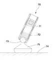
또 다른 종래의 정전식 터치펜(70)은 도 5에 도시된 바와 같이, 미국특허 제5999170호에 그 구성 및 구조가 공개되어 있는 바, 이를 요약 정리하면 다음과 같다.Another conventional
상기 정전식 터치펜(70)은 펜몸체(71)와 펜몸체(71)의 내측 일단부에 탄성체(72)에 의해 탄성적으로 삽설 지지되면서 회전이 자유로운 볼(73)과 상기 볼(73)에 연결 고정되고 단말기 등의 터치스크린(74)에 밀착되어 통전 감응시킬 수 있도록 된 터치부(75)로 구성되어 있다.The
따라서 단말기 등의 터치스크린(74)에 상기 터치부(75)를 밀착시키면서 상기 볼(73)을 회전시키면 사용자가 원하는 위치에 용이하게 터치될 수 있도록 하여 그편리성을 증가시킬 수 있는 구조로 되어 있다.
Therefore, when the
또 다른 종래의 터치펜(90)은 펜몸체(91)와 상기 펜몸체(91)의 단부에 구비되어 터치스크린(92)을 터치하여 클릭하는 펜고무부(93)가 구비된 구성으로 되어 있다.Another
여기서 종래의 상기 터치펜(90)에 구비된 상기 펜고무부(93)는 한쪽은 걸림턱(931)이 구비되어 상기 펜몸체(91)에 삽설 고정되고 다른 한쪽은 라운드부(932)를 이루면서 상기 터치스크린(92)을 용이하게 터치하여 클릭할 수 있도록 되고, 또 그 내부에는 공간부(933)가 형성되는 구조로 되어 있다.
Here, the
그러나 상기 종래와 같은 정전식 터치펜(50,70)은 단말기 등의 터치스크린과의 밀착성이 낮아 사용자가 원하는 자판의 문자나 아이콘 등의 클릭 성공률이 떨어진다고 하는 문제가 있다.However, the conventional
또한 상기 종래의 터치펜(90)은 그 터치부를 형성하는 펜고무부(93)의 내부가 공간부로 형성되어 있어 이를 터치스크린에 터치할 경우 다소 눌려지는 터치감을 주어 사용자의 클릭감을 저하시킨다는 단점이 있다.In addition, the
그리고 상기 종래의 터치펜(90)에 대한 또 다른 문제점은 터치스크린을 클릭하는 상기 펜고무부(93)의 단부가 라운드 모양으로 형성으로 되어 있어 이를 이용해 터치스크린에 구비된 각종 아이콘이나 기호 등을 지적할 경우 어느 것을 지적하는지 모호한 경우가 있어 사용상의 불편함이 있다는 것이다.In addition, another problem with the
이에 본 발명은 상기와 같은 문제를 해결하기 위해 안출된 것으로, 인체의 전류가 통전될 수 있도록 하는 터치펜 몸체를 구비하고 상기 몸체의 단부에 원형의 펜고무부를 설치 구비하되 상기 펜고무부의 내부에 형성된 공간부에 탄성수단이 구비된 제2펜고무부와 판스프링을 더 설치 구비하여, 펜고무부가 탄성적으로 터치스크린에 클릭하는 순간 제2펜고무부와 판스프링이 탄성적으로 상기 펜고무부의 내부에서 추가로 터치스크린을 가압할 수 있도록 함으로써 터치펜의 클릭감을 더욱 높여줄 수 있도록 함은 물론 펜고무부를 이용하여 터치스크린에 구비된 각종 문자나 아이콘 등을 용이하고 확실하게 지적할 수 있도록 하면서, 클릭성공률 또한 획기적으로 향상시킬 수 있도록 2중의 탄성력이 터치스크린에 가해질 수 있도록 된 정전식 터치펜을 제공하는데 그 목적이 있다.Accordingly, the present invention has been made to solve the above problems, provided with a touch pen body to enable the current of the human body to be energized and provided with a circular pen rubber portion at the end of the body inside the pen rubber portion The pen portion further includes a second pen rubber portion having a resilient means and a leaf spring, and the pen rubber portion and the leaf spring elastically resemble the pen rubber at the moment when the pen rubber portion elastically clicks on the touch screen. In addition to pressurizing the touch screen in the inside of the unit to increase the click pen's feeling of touch, as well as to easily and surely point out various characters or icons on the touch screen using the pen rubber unit. In addition, the capacitive touch pen, which allows double elastic force to be applied to the touch screen, can dramatically improve the click success rate. To have its purpose.
본 발명의 다른 목적은 상기 2중의 탄성력을 갖는 터치펜을 기존의 착탈식 안테나에 적용하여 그 안테나 일단부를 상기 터치펜으로 구성함으로써 기존의 정압식 터치펜이 구비된 착탈식 안테나를 정전식 터치펜과 겸용으로 사용할 수 있도록 하여 그 효용성을 극대화 할 수 있도록 하는데 있다.
Another object of the present invention is to apply the touch pen having a double elastic force to a conventional detachable antenna and to configure one end of the antenna as the touch pen, a detachable antenna equipped with a conventional hydrostatic touch pen combined with an electrostatic touch pen. It can be used to maximize the utility.
상기 목적을 달성하기 위한 본 발명은 휴대용 단말기, PDA 및 아이폰의 터치스크린을 터치하여 상기 터치스크린상에 있는 문자나 아이콘을 클릭할 수 있도록 하는 정전식 터치펜에 있어서,The present invention for achieving the above object in the capacitive touch pen to touch the touch screen of the portable terminal, PDA and iPhone to click on the characters or icons on the touch screen,
상기 정전식 터치펜은 로드(rod)형상의 터치펜몸체와,The capacitive touch pen includes a rod-shaped touch pen body,
상기 터치펜몸체의 한쪽 끝단부에 구비되고 그 단부가 라운드 형상으로 되어 터치스크린을 탄성적으로 터치/클릭할 수 있도록 된 펜고무부와,A pen rubber part provided at one end of the touch pen body and having an end portion having a round shape to elastically touch / click the touch screen;
상기 터치펜몸체의 내부에 구비되어 상기 펜고무부를 지지하여 고정할 수 있도록 된 펜고무지지체로 구성되되,Is provided in the touch pen body is composed of a pen rubber support to be fixed to support the pen rubber,
상기 펜고무부의 내부에 형성된 공간부에 구비되고 그 상단부는 상기 펜고무지지체의 하단면에 지지되어 고정 설치되며 하단부는 상기 펜고무부의 내부에 형성된 공간부의 내측 바닥면을 가압하도록 설치된 클릭탄성부로 구성되어 이루어진 것을 특징으로 한다.
It is provided in the space formed in the pen rubber portion, the upper end is supported and fixed to the lower surface of the pen rubber support, the lower end is composed of a click elastic portion installed to press the inner bottom surface of the space formed in the pen rubber portion Characterized in that made.
따라서 인체의 전류가 통전되도록 하여 단말기의 터치스크린을 효율적으로 터치/클릭할 수 있도록 하는 터치펜 몸체의 단부에 구비되는 펜고무부의 내부에 형성된 공간부에 탄성수단이 구비된 제2펜고무부와 상기 펜고무부 상부측으로 판스프링을 더 설치 구비하여 펜고무부가 탄성적으로 터치스크린에 클릭하는 순간 제2펜고무부와 판스프링이 탄성적으로 상기 펜고무부의 내부에서 추가로 터치스크린을 가압할 수 있도록 함으로써, 터치펜의 펜고무부가 터치스크린에 가압되면서 탄성적으로 눌려져 클릭하고자 하는 부분을 정확하게 터치/클릭할 수 있어, 터치펜의 클릭감을 높여줄 수 있음은 물론 클릭성공률 또한 획기적으로 향상시킬 수 있어 사용자의 편의성과 활용성을 배가시킬 수 있는 효과가 있다.Therefore, the second pen rubber unit having elastic means is provided in the space formed in the pen rubber unit provided at the end of the touch pen body to allow electric current of the human body to be energized so as to efficiently touch / click the touch screen of the terminal. The pen rubber part is further provided with an upper side of the pen rubber part so that the second pen rubber part and the leaf spring elastically press the touch screen in the pen rubber part at the moment when the pen rubber part elastically clicks on the touch screen. By allowing the pen rubber portion of the touch pen to be pressed on the touch screen elastically, it is possible to accurately touch / click the portion to be clicked, thereby increasing the click feeling of the touch pen and also significantly improving the click success rate. There is an effect that can double the user's convenience and usability.
또한 펜고무부를 이용하여 터치스크린에 구비된 각종 문자나 아이콘 등을 용이하고 확실하게 지적할 수 있어 사용상 편리하다.In addition, it is convenient for use because it can easily and surely point out various characters or icons provided on the touch screen using the pen rubber unit.
그리고 본 발명의 2중 탄성력을 갖는 정전식 터치펜은 기존의 정압식 터치펜을 구비한 착탈식 안테나의 일측에 구비되도록 함으로써 정압식과 정전식 겸용으로 착탈식 안테나를 사용할 수 있어 그 효용성이 획기적으로 향상되는 효과가 있다.
In addition, the capacitive touch pen having a double elastic force of the present invention is provided on one side of a detachable antenna having a conventional hydrostatic touch pen, so that the detachable antenna can be used for both the hydrostatic and the electrostatic capacities. It works.
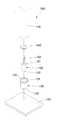
도 1은 본 발명에 따른 2중의 탄성력을 갖는 정전식 터치펜의 개략적인 상태단면도이고,
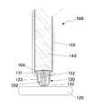
도 2는 본 발명에 따른 2중의 탄성력을 갖는 정전식 터치펜의 요부 분리 사시상태도이고,
도 3은 본 발명에 따른 2중의 탄성력을 갖는 정전식 터치펜이 터치스크린에 터치되어 클릭하여 작동된 상태단면도이고,
도 4 내지 6은 종래의 정전식 터치펜을 나타낸 상태도이다.1 is a schematic cross-sectional view of a capacitive touch pen having a double elastic force according to the present invention,
2 is a perspective view of a main portion separated perspective of the capacitive touch pen having a double elastic force according to the present invention;
3 is a cross-sectional view of a capacitive touch pen having a double elastic force according to the present invention operated by touching the touch screen by clicking.
4 to 6 is a state diagram showing a conventional capacitive touch pen.
이하, 본 발명의 바람직한 실시 예를 첨부한 도면을 참조하여 당해 분야에서 통상의 지식을 가진 자가 용이하게 실시할 수 있도록 설명한다.DETAILED DESCRIPTION OF THE PREFERRED EMBODIMENTS Hereinafter, preferred embodiments of the present invention will be described with reference to the accompanying drawings.
본 발명에 따른 2중의 탄성력을 갖는 정전식 터치펜(100)은 도 1에 도시되어 있는 바와 같이, 사용자가 손으로 잡을 수 있는 로드(rod)형상의 터치펜몸체(110)와,As shown in FIG. 1, the
상기 터치펜몸체(110)의 한쪽 끝단부에 구비되고 그 단부가 라운드 형상으로 되어 터치스크린(120)을 탄성적으로 터치/클릭할 수 있도록 된 펜고무부(130)와,A
상기 터치펜몸체(110)의 내부에 구비되어 상기 펜고무부(130)를 지지하여 고정할 수 있도록 된 펜고무지지체(140)와,A
상기 펜고무부(130)의 내부에 형성된 공간부에 구비되되 그 상단부는 상기 펜고무지지체(140)의 하단면에 지지되어 고정 설치되고 하단부는 상기 펜고무부(130)의 내부에 형성된 공간부의 내측 바닥면을 가압하여 바닥면이 볼록하게 형성되도록 설치된 클릭탄성부(150)와,It is provided in the space formed in the
상기 펜고무지지체(140)의 하부측에 구비되어 상기 펜고무부(130)와 상기 클릭탄성부(150)를 탄성적으로 지지하면서 이들의 터치/클릭감을 높여줄 수 있도록 된 판스프링(160)으로 구성되어 이루어진다.The
여기서 상기 펜고무부(130)는 그 일단은 걸림턱(131)이 형성되어 상기 터치펜몸체(110)의 내부 하단부에 삽설 구비되고, 타단은 원형 모양의 라운드부(132)로 형성되어 상기 터치스크린(120)을 용이하게 클릭할 수 있도록 되며, 내부는 상기 라운드부(132)가 상기 터치스크린(120)을 터치 클릭할 때 탄성력이 발휘될 수 있도로 공간부(133)가 형성되는 구조로 되어 있다.Here, the
그리고 상기 클릭탄성부(150)는 상단부측으로 개방된 요홈부(151)가 형성되어 있고, 상기 요홈부(151)에는 상기 클릭탄성부(150)가 탄성력을 발휘할 수 있도록 하는 탄성수단(152)이 삽입 설치되어 제2펜고무부가 이루어지도록 하는 구조로 되어 있다.In addition, the click
여기서 상기 탄성수단(152)은 주로 스프링과 같은 탄성체가 사용되나 스프링 이외의 다른 탄성체로 사용될 수 있음은 물론이다.Here, the
그리고 상기 클릭탄성부(150)의 상단부에 형성된 상기 요홈부(151)의 반대측 즉, 상기 클릭탄성부(150)의 하단부측은 그 단부가 상기 펜고무부(130)의 내부에 형성된 상기 공간부(133) 내벽면을 눌러 가압해 주는 라운드가 형성된 원추형상부(153)가 형성되는 구조로 되어 있다.And the opposite side of the
따라서 도 2과 같이 상기 펜고무부(130)에 구비된 상기 라운드부(132)는 상기 탄성수단(152)과 상기 원추형상부(153)에 의해 그 최하단부가 볼록하게 돌출되어 터치스크린(120) 상의 기호나 문자 및 아이콘 등을 효과적으로 지적할 수 있게 된다.Accordingly, as shown in FIG. 2, the
상기와 같이 상기 펜고무부(130)의 내부에 형성된 상기 공간부(133)에 상기 클릭탄성부(150)가 가압되어 상기 라운드부(132)를 볼록하게 구성함으로써, 상기 펜고무부(130)가 상기 터치스크린(120) 상의 아이콘 등을 용이하게 지적하고 또 상기 클릭탄성부(150)에 형성된 상기 원추형상부(153)가 상기 탄성수단(152)과 상기 판스프링(160)에 의해 탄성적으로 상기 라운드부(132)를 가압하여 2중으로 상기 터치스크린(120)을 터치 클릭할 수 있도록 작용하게 되어 클릭감을 더욱 높여줄 수 있게 된다.
As described above, the click
이와 같이 상기 펜고무부(130)가 상기 터치스크린(120)을 터치하여 탄성적으로 클릭할 때 상기 판스프링(160)과 상기 탄성수단(152)에 의해 상기 펜고무부(130)의 내부에서 상기 원추형상부(153)가 추가적으로(2중으로) 상기 터치스크린(120)을 터치하여 클릭함으로써, 상기 펜고무부(130)가 상기 터치스크린(120)을 터치할 때 눌려지는 터치감 즉 클릭감이 향상될 수 있게 되는 것이다.As described above, when the
따라서 상기 펜고무부(130) 단독으로 터치스크린(120)을 터치하여 클릭할 때의 클릭성공률보다 상기 클릭탄성부(150)와 상기 판스프링(160)을 설치하여 2중으로 터치스크린(120)을 터치하여 클릭할 때의 클릭성공률이 획기적으로 향상될 수 있게 된다.Therefore, the click
즉, 상기 펜고무부(130)를 아이폰이나 PDA 등의 패널이나 터치스크린(120)에 정위(定位)시키고자 할 경우 그 밀착력이 2중의 탄성력으로 이루어져 클릭감의 향상과 더불어 클릭성공률도 상술한 바와 같이 획기적으로 향상될 수 있게 된다.
That is, when the
여기서 상기 펜고무부(130)는 사용자의 인체에서 발생되는 미세 전류가 상기 터치펜몸체(110)를 통해 통전되는 재질로 구성되고 또 상기 터치스크린(120)에 부드럽게 밀착되도록 긴밀성을 갖는 고무재질 또는 이와 유사한 재질로 되고, 또한 상기 클릭탄성부(150)와 상기 판스프링(160) 역시 상기 펜고무부(130)와 마찬가지로 인체의 미세한 전류가 통전될 수 있도록 하는 재질로 구비됨은 물론이다.
Here, the
상기와 같이 구성된 본 발명의 상기 정전식 터치펜(100)은 도1 내지 도3에 도시되어 있는 바와 같이, 사용자가 상기 터치펜몸체(110)를 잡고 터치스크린(120)에 문자나 아이콘 등을 지적하고자 할 경우, 상기 펜고무부(130)의 볼록한 상기 라운드부(132)가 상기 터치스크린(120) 상에 구비된 아이콘 등을 편리하고 용이하게 지적할 수 있게 된다.In the
이를 좀더 상세히 설명하면, 도 3에 도시된 바와 같이, 상기 펜고무부(130)를 이용하여 상기 터치스크린(120) 상에 구비된 문자 기호 아이콘 등을 지적하기 위해서는 상기 원뿔형상부(153)에 의해 탄성적으로 밀려 볼록하게 형성된 상기 라운드부(132)에 의해 이들을 용이하게 표시 지적할 수 있게 된다.
In more detail, as shown in FIG. 3, in order to point out a letter symbol icon or the like provided on the
그와 동시에 상기 라운드부(132)를 이용하여 터치스크린(120)의 아이콘을 가압 클릭하게 되면, 상기 클릭탄성부(150)의 상기 요홈부(151)에 구비된 상기 탄성수단(152)과 상기 판스프링(160)이 탄성력을 발휘하면서 상기 원추형상부(153)가 상기 펜고무부(130)의 라운드부(132) 내벽을 탄성적으로 지지하여 준다.At the same time, when pressing the icon of the
이때 상기 원추형상부(153)와 상기 라운드부(132)가 동시에 탄성력을 발휘하여 2중의 탄성력으로 터치스크린(120)을 터치 클릭하게 된다.
At this time, the
따라서 사용자는 상기 터치스크린(120) 상의 어느 아이콘이나 문자 등을 지적하거나 또는 클릭하여도 그 해당 작업이 효과적으로 이루어 질 수 있게 되는 것이다. 즉, 지적(指摘)으로 인한 표시작업과 클릭작업의 성공률이 획기적으로 향상될 수 있게 된다.
Accordingly, the user can effectively perform the corresponding operation even when pointing or clicking on any icon or text on the
또한, 상기와 같은 2중의 탄성력을 갖는 정전식 터치펜(100)은 이를 기존 착탈식 안테나에 적용 될 수 있다. 즉 기존의 착탈식 안테나는 안테나몸통과 정압식 터치펜 및 상기 정압식 터치펜을 보호할 수 있도록 하는 보호캡으로 구성되어 있는 바, 상기 안테나몸통의 일단에는 상기 정압식 터치펜이 연결 설치되고 또 상기 안테나몸통의 타단에는 상기 정전식 터치펜(100)을 구비하여 상기 터치펜몸체(110)를 안테나로 이용할 수 있도록 함으로써, 착탈식 안테나에 정전식과 정압식의 터치펜을 겸용으로 구비할 수 있어 사용상 매우 효율적으로 활용될 수 있다.In addition, the
따라서 기존의 착탈식 안테나의 일단부에 정전식 터치펜이 구비되고 타단부에는 정압식 터치펜이 구비되도록 함으로써, 사용자의 편의성이 더 한층 제고될 수 있게 된다.
Therefore, the capacitive touch pen is provided at one end of the existing detachable antenna and the static pressure touch pen is provided at the other end, whereby user convenience can be further enhanced.
100:정전식 터치펜 110:터치펜몸체 120:터치스크린 130:펜고무부
140:펜고무지지체 150:클릭탄성부 160:판스프링
131:걸림턱 132:라운드부 133:공간부 151:요홈부 152:탄성수단
153:원추형상부100: electrostatic touch pen 110: touch pen body 120: touch screen 130: pen rubber department
140: Pen rubber support 150: Click elastic part 160: Leaf spring
131: locking jaw 132: round portion 133: space portion 151: groove portion 152: elastic means
153: conical shape
Claims (4)
Translated fromKorean상기 정전식 터치펜은
로드(rod)형상의 터치펜몸체(110)와,
상기 터치펜몸체(110)의 한쪽 끝단부에 구비되고 그 단부가 라운드 형상으로 되어 터치스크린(120)을 탄성적으로 터치/클릭할 수 있도록 된 펜고무부(130)와,
상기 터치펜몸체(110)의 내부에 구비되어 상기 펜고무부(130)를 지지하여 고정할 수 있도록 된 펜고무지지체(140)로 구성되되,
상기 펜고무부(130)의 내부에 형성된 공간부에 구비되고 그 상단부는 상기 펜고무지지체(140)의 하단면에 지지되어 고정 설치되며 하단부는 상기 펜고무부(130)의 내부에 형성된 공간부의 내측 바닥면을 가압하여 상기 바닥면이 볼록하게 형성되도록 설치된 클릭탄성부(150)로 구성되어 이루어진 것을 특징으로 하는 2중의 탄성력을 갖는 정전식 터치펜.
In the capacitive touch pen to touch the touch screen of the portable terminal, PDA and iPhone to click on the characters or icons on the touch screen,
The capacitive touch pen
Rod-shaped touch pen body 110,
A pen rubber part 130 provided at one end of the touch pen body 110 and having an end thereof in a round shape so as to elastically touch / click the touch screen 120;
Is provided in the inside of the touch pen body 110 is composed of a pen rubber support 140 to be fixed by supporting the pen rubber portion 130,
It is provided in the space portion formed inside the pen rubber portion 130, the upper end is supported and fixed to the lower surface of the pen rubber support 140, the lower portion of the space formed in the pen rubber portion 130 The electrostatic touch pen having a double elastic force, characterized in that consisting of a click elastic portion 150 is installed so that the bottom surface is convex by pressing the inner bottom surface.
상기 클릭탄성부(150)는 상단부측으로 개방된 요홈부(151)가 형성되어 있고, 상기 요홈부(151)에는 상기 클릭탄성부(150)가 탄성력을 발휘할 수 있도록 하는 탄성수단(152)이 삽입 설치되는 구조로 이루어진 것을 특징으로 하는 2중의 탄성력을 갖는 정전식 터치펜.
The method of claim 1,
The click elastic part 150 is formed with a recess 151 open toward the upper end side, and the recess 151 is inserted into the recess 151 to allow the click elastic part 150 to exert an elastic force. The capacitive touch pen having a double elastic force, characterized in that the structure is installed.
상기 클릭탄성부(150)의 하단부측은 그 단부가 상기 펜고무부(130)의 내부에 형성된 상기 공간부(133)의 내측 바닥면을 가압하도록 하는 라운드가 형성된 원추형상부(153)가 구비되어 이루어진 것을 특징으로 하는 2중의 탄성력을 갖는 정전식 터치펜.
The method of claim 2,
The lower end side of the click elastic portion 150 is provided with a conical portion 153 is formed with a round end to press the inner bottom surface of the space portion 133 formed inside the pen rubber portion 130 A capacitive touch pen having a double elastic force, characterized in that.
상기 펜고무지지체(140)의 하부측에는 상기 펜고무부(130)와 상기 클릭탄성부(150)를 탄성적으로 지지하면서 이들의 터치/클릭감을 높여줄 수 있도록 된 판스프링(160)이 더 구비되어 이루어진 것을 특징으로 하는 2중의 탄성력을 갖는 정전식 터치펜.The method of claim 1,
The lower side of the pen rubber support 140 is further provided with a leaf spring 160 to elastically support the pen rubber portion 130 and the click elastic portion 150 to increase their touch / click feeling Capacitive touch pen having a double elastic force, characterized in that made.
Priority Applications (1)
| Application Number | Priority Date | Filing Date | Title |
|---|---|---|---|
| KR1020100051756AKR20110131989A (en) | 2010-06-01 | 2010-06-01 | Capacitive touch pen with double elastic force |
Applications Claiming Priority (1)
| Application Number | Priority Date | Filing Date | Title |
|---|---|---|---|
| KR1020100051756AKR20110131989A (en) | 2010-06-01 | 2010-06-01 | Capacitive touch pen with double elastic force |
Publications (1)
| Publication Number | Publication Date |
|---|---|
| KR20110131989Atrue KR20110131989A (en) | 2011-12-07 |
Family
ID=45500269
Family Applications (1)
| Application Number | Title | Priority Date | Filing Date |
|---|---|---|---|
| KR1020100051756AWithdrawnKR20110131989A (en) | 2010-06-01 | 2010-06-01 | Capacitive touch pen with double elastic force |
Country Status (1)
| Country | Link |
|---|---|
| KR (1) | KR20110131989A (en) |
Cited By (2)
| Publication number | Priority date | Publication date | Assignee | Title |
|---|---|---|---|---|
| US10488951B2 (en) | 2015-01-27 | 2019-11-26 | Samsung Electronics Co., Ltd. | Stylus pen and touch panel configured to detect input position and input pressure |
| KR102827443B1 (en)* | 2024-09-30 | 2025-07-02 | 프레임바이 주식회사 | Pen tip structure for electronic stylus pen |
- 2010
- 2010-06-01KRKR1020100051756Apatent/KR20110131989A/ennot_activeWithdrawn
Cited By (2)
| Publication number | Priority date | Publication date | Assignee | Title |
|---|---|---|---|---|
| US10488951B2 (en) | 2015-01-27 | 2019-11-26 | Samsung Electronics Co., Ltd. | Stylus pen and touch panel configured to detect input position and input pressure |
| KR102827443B1 (en)* | 2024-09-30 | 2025-07-02 | 프레임바이 주식회사 | Pen tip structure for electronic stylus pen |
Similar Documents
| Publication | Publication Date | Title |
|---|---|---|
| KR200455484Y1 (en) | Capacitive touch pen | |
| JP5369122B2 (en) | Stylus for capacitive touch panel | |
| CN101598979A (en) | The soft handwriting pen that matching with capacitive touch screen uses | |
| US20150029161A1 (en) | Methods and apparatus for implementing dual tip functionality in a stylus device | |
| CN107003788B (en) | Electronic device and method of operating the same | |
| US20130141400A1 (en) | Stylus | |
| KR20140129812A (en) | Touch pad having force sensor and input method using the same | |
| KR20110110686A (en) | Capacitive Touch Pen Structure | |
| CN102207777B (en) | Capacitive touch pen | |
| KR100985062B1 (en) | Conductive type touch pen | |
| CN204496445U (en) | A kind of capacitance pen for accurately inputting and capacitive touch control | |
| JP4931616B2 (en) | Input aid | |
| CN201773366U (en) | Stylus for use with capacitive touchscreens | |
| KR20110131989A (en) | Capacitive touch pen with double elastic force | |
| US9310899B2 (en) | Stylus having head being rigid body and electronic device using the same | |
| CN202486717U (en) | Stylus structure | |
| KR20080079858A (en) | Mobile communication terminal with input device | |
| KR20110130799A (en) | Capacitive touch pen | |
| KR100984152B1 (en) | Conductive type touch pen | |
| JP5944209B2 (en) | Information input pen | |
| CN205656593U (en) | A new capacitive stylus | |
| CN103176626B (en) | Stylus | |
| CN101470546A (en) | Touch control pen and electronic device | |
| CN212731023U (en) | Touch screen auxiliary device | |
| CN201107766Y (en) | Touch control assembly for capacitive panel |
Legal Events
| Date | Code | Title | Description |
|---|---|---|---|
| PA0109 | Patent application | Patent event code:PA01091R01D Comment text:Patent Application Patent event date:20100601 | |
| PG1501 | Laying open of application | ||
| PC1203 | Withdrawal of no request for examination | ||
| WITN | Application deemed withdrawn, e.g. because no request for examination was filed or no examination fee was paid |